JP6641375B2 - Intraoperative detection head now coupled to ablation tool - Google Patents
Intraoperative detection head now coupled to ablation tool Download PDFInfo
- Publication number
- JP6641375B2 JP6641375B2 JP2017534255A JP2017534255A JP6641375B2 JP 6641375 B2 JP6641375 B2 JP 6641375B2 JP 2017534255 A JP2017534255 A JP 2017534255A JP 2017534255 A JP2017534255 A JP 2017534255A JP 6641375 B2 JP6641375 B2 JP 6641375B2
- Authority
- JP
- Japan
- Prior art keywords
- signal
- tissue
- probe
- optical fiber
- fiber
- Prior art date
- Legal status (The legal status is an assumption and is not a legal conclusion. Google has not performed a legal analysis and makes no representation as to the accuracy of the status listed.)
- Active
Links
- 238000001514 detection method Methods 0.000 title claims description 96
- 238000002679 ablation Methods 0.000 title description 11
- 239000000835 fiber Substances 0.000 claims description 97
- 239000000523 sample Substances 0.000 claims description 76
- 239000013307 optical fiber Substances 0.000 claims description 30
- 239000000700 radioactive tracer Substances 0.000 claims description 23
- 238000002271 resection Methods 0.000 claims description 21
- 239000002245 particle Substances 0.000 claims description 19
- 230000003287 optical effect Effects 0.000 claims description 18
- 230000008878 coupling Effects 0.000 claims description 16
- 238000010168 coupling process Methods 0.000 claims description 16
- 238000005859 coupling reaction Methods 0.000 claims description 16
- 230000005284 excitation Effects 0.000 claims description 15
- 230000005855 radiation Effects 0.000 claims description 14
- 238000004458 analytical method Methods 0.000 claims description 11
- 238000004891 communication Methods 0.000 claims description 7
- 230000002285 radioactive effect Effects 0.000 claims description 7
- 239000004020 conductor Substances 0.000 claims description 6
- 230000000295 complement effect Effects 0.000 claims description 3
- XUIMIQQOPSSXEZ-UHFFFAOYSA-N Silicon Chemical compound [Si] XUIMIQQOPSSXEZ-UHFFFAOYSA-N 0.000 claims description 2
- 229910052710 silicon Inorganic materials 0.000 claims description 2
- 239000010703 silicon Substances 0.000 claims description 2
- 238000000034 method Methods 0.000 description 33
- 206010028980 Neoplasm Diseases 0.000 description 24
- 238000001356 surgical procedure Methods 0.000 description 24
- 230000005540 biological transmission Effects 0.000 description 21
- 208000002847 Surgical Wound Diseases 0.000 description 12
- 238000013507 mapping Methods 0.000 description 11
- 238000003384 imaging method Methods 0.000 description 10
- 238000005259 measurement Methods 0.000 description 9
- 230000000875 corresponding effect Effects 0.000 description 8
- 230000003902 lesion Effects 0.000 description 7
- 239000013306 transparent fiber Substances 0.000 description 6
- 210000004556 brain Anatomy 0.000 description 5
- 230000004807 localization Effects 0.000 description 5
- 239000000463 material Substances 0.000 description 5
- 230000001443 photoexcitation Effects 0.000 description 5
- 230000035945 sensitivity Effects 0.000 description 5
- 230000008901 benefit Effects 0.000 description 4
- 238000001574 biopsy Methods 0.000 description 4
- 238000012986 modification Methods 0.000 description 4
- 230000004048 modification Effects 0.000 description 4
- 238000003199 nucleic acid amplification method Methods 0.000 description 4
- 238000003325 tomography Methods 0.000 description 4
- 238000002604 ultrasonography Methods 0.000 description 4
- 230000003321 amplification Effects 0.000 description 3
- 238000006243 chemical reaction Methods 0.000 description 3
- 230000008569 process Effects 0.000 description 3
- 208000003174 Brain Neoplasms Diseases 0.000 description 2
- 208000032612 Glial tumor Diseases 0.000 description 2
- 206010018338 Glioma Diseases 0.000 description 2
- 201000011510 cancer Diseases 0.000 description 2
- 238000006073 displacement reaction Methods 0.000 description 2
- 238000005516 engineering process Methods 0.000 description 2
- 230000005389 magnetism Effects 0.000 description 2
- 230000002503 metabolic effect Effects 0.000 description 2
- 229910052751 metal Inorganic materials 0.000 description 2
- 239000002184 metal Substances 0.000 description 2
- 238000012545 processing Methods 0.000 description 2
- 230000004044 response Effects 0.000 description 2
- 238000001228 spectrum Methods 0.000 description 2
- 208000026310 Breast neoplasm Diseases 0.000 description 1
- OKTJSMMVPCPJKN-UHFFFAOYSA-N Carbon Chemical compound [C] OKTJSMMVPCPJKN-UHFFFAOYSA-N 0.000 description 1
- 206010019695 Hepatic neoplasm Diseases 0.000 description 1
- 229910052765 Lutetium Inorganic materials 0.000 description 1
- 206010052428 Wound Diseases 0.000 description 1
- 208000027418 Wounds and injury Diseases 0.000 description 1
- 230000002411 adverse Effects 0.000 description 1
- 210000003484 anatomy Anatomy 0.000 description 1
- 238000013459 approach Methods 0.000 description 1
- 230000008033 biological extinction Effects 0.000 description 1
- 210000000481 breast Anatomy 0.000 description 1
- 238000004364 calculation method Methods 0.000 description 1
- 229910052799 carbon Inorganic materials 0.000 description 1
- 210000003169 central nervous system Anatomy 0.000 description 1
- 230000002596 correlated effect Effects 0.000 description 1
- 238000013461 design Methods 0.000 description 1
- 230000009365 direct transmission Effects 0.000 description 1
- 230000008034 disappearance Effects 0.000 description 1
- 238000002224 dissection Methods 0.000 description 1
- 230000005489 elastic deformation Effects 0.000 description 1
- 230000005670 electromagnetic radiation Effects 0.000 description 1
- 238000001839 endoscopy Methods 0.000 description 1
- 238000011156 evaluation Methods 0.000 description 1
- 238000002189 fluorescence spectrum Methods 0.000 description 1
- -1 for example Substances 0.000 description 1
- 230000005251 gamma ray Effects 0.000 description 1
- 238000010438 heat treatment Methods 0.000 description 1
- 230000001771 impaired effect Effects 0.000 description 1
- 238000012977 invasive surgical procedure Methods 0.000 description 1
- 208000014018 liver neoplasm Diseases 0.000 description 1
- OHSVLFRHMCKCQY-UHFFFAOYSA-N lutetium atom Chemical compound [Lu] OHSVLFRHMCKCQY-UHFFFAOYSA-N 0.000 description 1
- 239000003550 marker Substances 0.000 description 1
- 230000001394 metastastic effect Effects 0.000 description 1
- 206010061289 metastatic neoplasm Diseases 0.000 description 1
- 238000012544 monitoring process Methods 0.000 description 1
- 230000001613 neoplastic effect Effects 0.000 description 1
- 238000010899 nucleation Methods 0.000 description 1
- 231100000590 oncogenic Toxicity 0.000 description 1
- 230000002246 oncogenic effect Effects 0.000 description 1
- 210000000056 organ Anatomy 0.000 description 1
- 230000003071 parasitic effect Effects 0.000 description 1
- 238000010827 pathological analysis Methods 0.000 description 1
- 230000001575 pathological effect Effects 0.000 description 1
- 230000002980 postoperative effect Effects 0.000 description 1
- 238000004393 prognosis Methods 0.000 description 1
- 238000011002 quantification Methods 0.000 description 1
- 238000005070 sampling Methods 0.000 description 1
- 238000000926 separation method Methods 0.000 description 1
- 238000011895 specific detection Methods 0.000 description 1
- 210000000278 spinal cord Anatomy 0.000 description 1
- 229910001220 stainless steel Inorganic materials 0.000 description 1
- 239000010935 stainless steel Substances 0.000 description 1
- 239000013589 supplement Substances 0.000 description 1
- 238000012360 testing method Methods 0.000 description 1
- 238000012876 topography Methods 0.000 description 1
- 230000000472 traumatic effect Effects 0.000 description 1
Images


Classifications
-
- A—HUMAN NECESSITIES
- A61—MEDICAL OR VETERINARY SCIENCE; HYGIENE
- A61B—DIAGNOSIS; SURGERY; IDENTIFICATION
- A61B6/00—Apparatus or devices for radiation diagnosis; Apparatus or devices for radiation diagnosis combined with radiation therapy equipment
- A61B6/44—Constructional features of apparatus for radiation diagnosis
- A61B6/4411—Constructional features of apparatus for radiation diagnosis the apparatus being modular
-
- A—HUMAN NECESSITIES
- A61—MEDICAL OR VETERINARY SCIENCE; HYGIENE
- A61B—DIAGNOSIS; SURGERY; IDENTIFICATION
- A61B5/00—Measuring for diagnostic purposes; Identification of persons
- A61B5/0059—Measuring for diagnostic purposes; Identification of persons using light, e.g. diagnosis by transillumination, diascopy, fluorescence
- A61B5/0071—Measuring for diagnostic purposes; Identification of persons using light, e.g. diagnosis by transillumination, diascopy, fluorescence by measuring fluorescence emission
-
- A—HUMAN NECESSITIES
- A61—MEDICAL OR VETERINARY SCIENCE; HYGIENE
- A61B—DIAGNOSIS; SURGERY; IDENTIFICATION
- A61B5/00—Measuring for diagnostic purposes; Identification of persons
- A61B5/0033—Features or image-related aspects of imaging apparatus classified in A61B5/00, e.g. for MRI, optical tomography or impedance tomography apparatus; arrangements of imaging apparatus in a room
- A61B5/0035—Features or image-related aspects of imaging apparatus classified in A61B5/00, e.g. for MRI, optical tomography or impedance tomography apparatus; arrangements of imaging apparatus in a room adapted for acquisition of images from more than one imaging mode, e.g. combining MRI and optical tomography
-
- A—HUMAN NECESSITIES
- A61—MEDICAL OR VETERINARY SCIENCE; HYGIENE
- A61B—DIAGNOSIS; SURGERY; IDENTIFICATION
- A61B6/00—Apparatus or devices for radiation diagnosis; Apparatus or devices for radiation diagnosis combined with radiation therapy equipment
- A61B6/42—Arrangements for detecting radiation specially adapted for radiation diagnosis
- A61B6/4208—Arrangements for detecting radiation specially adapted for radiation diagnosis characterised by using a particular type of detector
- A61B6/425—Arrangements for detecting radiation specially adapted for radiation diagnosis characterised by using a particular type of detector using detectors specially adapted to be used in the interior of the body
-
- A—HUMAN NECESSITIES
- A61—MEDICAL OR VETERINARY SCIENCE; HYGIENE
- A61B—DIAGNOSIS; SURGERY; IDENTIFICATION
- A61B6/00—Apparatus or devices for radiation diagnosis; Apparatus or devices for radiation diagnosis combined with radiation therapy equipment
- A61B6/44—Constructional features of apparatus for radiation diagnosis
- A61B6/4417—Constructional features of apparatus for radiation diagnosis related to combined acquisition of different diagnostic modalities
-
- H—ELECTRICITY
- H04—ELECTRIC COMMUNICATION TECHNIQUE
- H04B—TRANSMISSION
- H04B10/00—Transmission systems employing electromagnetic waves other than radio-waves, e.g. infrared, visible or ultraviolet light, or employing corpuscular radiation, e.g. quantum communication
- H04B10/80—Optical aspects relating to the use of optical transmission for specific applications, not provided for in groups H04B10/03 - H04B10/70, e.g. optical power feeding or optical transmission through water
-
- A—HUMAN NECESSITIES
- A61—MEDICAL OR VETERINARY SCIENCE; HYGIENE
- A61B—DIAGNOSIS; SURGERY; IDENTIFICATION
- A61B17/00—Surgical instruments, devices or methods, e.g. tourniquets
- A61B17/32—Surgical cutting instruments
- A61B17/3205—Excision instruments
-
- A—HUMAN NECESSITIES
- A61—MEDICAL OR VETERINARY SCIENCE; HYGIENE
- A61B—DIAGNOSIS; SURGERY; IDENTIFICATION
- A61B18/00—Surgical instruments, devices or methods for transferring non-mechanical forms of energy to or from the body
- A61B2018/00571—Surgical instruments, devices or methods for transferring non-mechanical forms of energy to or from the body for achieving a particular surgical effect
- A61B2018/00577—Ablation
-
- A—HUMAN NECESSITIES
- A61—MEDICAL OR VETERINARY SCIENCE; HYGIENE
- A61B—DIAGNOSIS; SURGERY; IDENTIFICATION
- A61B2560/00—Constructional details of operational features of apparatus; Accessories for medical measuring apparatus
- A61B2560/04—Constructional details of apparatus
- A61B2560/0443—Modular apparatus
-
- A—HUMAN NECESSITIES
- A61—MEDICAL OR VETERINARY SCIENCE; HYGIENE
- A61B—DIAGNOSIS; SURGERY; IDENTIFICATION
- A61B5/00—Measuring for diagnostic purposes; Identification of persons
- A61B5/0059—Measuring for diagnostic purposes; Identification of persons using light, e.g. diagnosis by transillumination, diascopy, fluorescence
- A61B5/0082—Measuring for diagnostic purposes; Identification of persons using light, e.g. diagnosis by transillumination, diascopy, fluorescence adapted for particular medical purposes
- A61B5/0084—Measuring for diagnostic purposes; Identification of persons using light, e.g. diagnosis by transillumination, diascopy, fluorescence adapted for particular medical purposes for introduction into the body, e.g. by catheters
Landscapes
- Health & Medical Sciences (AREA)
- Life Sciences & Earth Sciences (AREA)
- Engineering & Computer Science (AREA)
- Medical Informatics (AREA)
- Physics & Mathematics (AREA)
- Heart & Thoracic Surgery (AREA)
- Veterinary Medicine (AREA)
- Nuclear Medicine, Radiotherapy & Molecular Imaging (AREA)
- Public Health (AREA)
- Pathology (AREA)
- General Health & Medical Sciences (AREA)
- Biomedical Technology (AREA)
- Biophysics (AREA)
- Molecular Biology (AREA)
- Surgery (AREA)
- Animal Behavior & Ethology (AREA)
- Radiology & Medical Imaging (AREA)
- Optics & Photonics (AREA)
- High Energy & Nuclear Physics (AREA)
- Electromagnetism (AREA)
- Computer Networks & Wireless Communication (AREA)
- Signal Processing (AREA)
- Investigating, Analyzing Materials By Fluorescence Or Luminescence (AREA)
- Endoscopes (AREA)
Description
本発明は、生物学的組織、特に癌性腫瘍の外科的治療の補助に関する。 The present invention relates to assisting surgical treatment of biological tissues, especially cancerous tumors.
癌の外科的治療の補助は、現在、幾つかの技術に基づいている。 Assisting surgical treatment of cancer is currently based on several techniques.
「術前イメージング法」と呼ばれる第1の術式では、手術前に、外科医は、切除されるべき組織部分の存在場所をできるだけ十分に突き止めるために治療されるべき組織野のイメージを作る。 In a first procedure, referred to as "pre-operative imaging", prior to surgery, the surgeon creates an image of the tissue field to be treated to locate the tissue portion to be resected as fully as possible.
腫瘍の存在場所の事前突き止めは、X線トモグラフィまたはIRMによって、例えば、腫瘍状ボリュームの正確な解剖学的トポグラフィを得、かくして最も適切な進入路を選択するために用いられる。機械的定位案内または光案内と結合されると、術前存在場所突き止めにより、より狭く定められ、したがって外傷性の低いアクセス経路が特に深部病変の場合に得られる。 Prelocating the location of the tumor is used by X-ray tomography or IRM, for example, to obtain an accurate anatomical topography of the tumorous volume and thus to select the most appropriate approach. When combined with mechanical stereotactic or optical guidance, pre-operative localization provides a narrower, and thus less traumatic, access path, especially in the case of deep lesions.
神経外科では、この技術は、腫瘍の近くに位置する機能的脳区域を正確に識別するために外科的処置の前に用いられる機能的等温残留磁気(IRM)イメージング装置の使用によって補完されるのが良い。この情報に基づいて、次に、外科医は、切除されるべき区域の広がりを最適化する一方で更に術後罹患率のリスクを最小限に抑えることができる。 In neurosurgery, this technique is complemented by the use of a functional isothermal remanent magnetism (IRM) imaging device used prior to the surgical procedure to accurately identify functional brain segments located near the tumor. Is good. Based on this information, the surgeon can then optimize the extent of the area to be resected while further minimizing the risk of postoperative morbidity.
術前イメージ法は、より正確でありかつ侵襲性の低い外科的処置の導入を可能にした。 Preoperative imaging has enabled the introduction of more accurate and less invasive surgical procedures.
しかしながら、これらの技術には、性能および人間工学的設計の面で制約がある。特に、これら技術は、小さな腫瘍およびこれらの転移性播種(もしあれば)の存在場所の突き止めを必要とする操作に不向きである。 However, these techniques have limitations in terms of performance and ergonomic design. In particular, these techniques are unsuitable for operations that require locating small tumors and their metastatic seeding, if any.
加うるに、外科的処置中における組織(特に、脳内の組織)の変位が手術前に行われた病変の存在場所を既に利用できない状態にする場合が多い。 In addition, the displacement of tissue (particularly tissue in the brain) during a surgical procedure often renders the location of a lesion performed before surgery no longer available.
第2の術式によれば、外科医は、手術中に組織検体を採取し、そしてこれら検体を即座に分析して外科医の手術手技の質を保証するようにする。 According to the second technique, the surgeon collects tissue samples during the operation and analyzes these samples immediately to ensure the quality of the surgeon's surgical procedure.
組織検体の正確な解剖病理学的診断を利用するこれら技術は、非常に信頼性が高いという利点を有する。 These techniques, which utilize accurate anatomical pathological diagnosis of tissue specimens, have the advantage of being very reliable.
しかしながら、かかる技術は極めてコスト高である。 However, such techniques are extremely costly.
加うるに、検体からの診断結果を得るのに必要な時間は、外科的処置の時間を著しく増加させる場合がある。 In addition, the time required to obtain a diagnostic result from a specimen can significantly increase the duration of a surgical procedure.
術前イメージ法および組織検体採取法と関連した欠点があると仮定した上で、「術中法」と呼ばれる第3の術式が現れた。これら技術は、手術室内で役立ち、かくして医師が腫瘍切除または生検の辺縁をより正確にかつリアルタイムに決定するのを助けることによって外部イメージャを補完する適当なモニタリングツールを採用している。 Assuming the shortcomings associated with preoperative imaging and tissue sampling, a third technique emerged, called "intraoperative". These techniques employ appropriate monitoring tools that are useful in the operating room and thus complement the external imager by helping physicians determine the margins of a tumor resection or biopsy more accurately and in real time.
2系統の術中法が現在研究されている。「解剖学的術中法」と呼ばれる第1の技術系統は、標準型解剖学的イメージングシステム、例えば光学内視鏡検査システム、超音波エコー診断法Xトモグラフィまたは等温残留磁気法(IRM)に基づいている。「機能的術中法」と呼ばれる第2の技術系統は、超小型化システムにより組織により放出される信号の検出に基づいている。かかる信号は、組織中に存在しかつ探している腫瘍病変に特有の放射性トレーサまたは蛍光分子によって放出される粒子または放射線である。 Two intraoperative regimens are currently being studied. The first line of technology, called "anatomical intra-operative procedures", is based on standard anatomical imaging systems, such as optical endoscopy systems, ultrasound echography X tomography or isothermal remanence magnetism (IRM). ing. A second family of technologies, called "functional intraoperative procedures", is based on the detection of signals emitted by tissues by microminiaturized systems. Such signals are particles or radiation emitted by radioactive tracers or fluorescent molecules present in the tissue and specific to the tumor lesion sought.
解剖学的術中法によれば、外科医は、自分の行為を誘導するために、原理が臨床診断部門で用いられている解剖学的イメージング装置と同一であるが寸法および人間工学的性質の面における特徴が手術室での使用に適合させた解剖学的イメージング装置を用いる。 According to the anatomical intraoperative method, the surgeon has the same principle as the anatomical imaging device used in the clinical diagnostic department to guide his actions, but in terms of dimensions and ergonomics. An anatomical imaging device is used whose features are adapted for use in the operating room.
術前検査の補完手段として、主として手術室内では、外科的処置中における組織の変位と関連した存在場所の誤差を是正して生検手技を誘導するために低磁界IRMおよびX線トモグラフィが用いられる。解剖学的イメージングシステムは、事実、かかる外科的処置の実施前に作られたイメージをリアルタイムで繰り返し、その結果として、解剖学的構造のディストーションをリアルタイムでモニタするために用いられている。かくして、グリオーマの手術のための術中IRMの評価結果の示すところによれば、これらの技術により術前イメージに用いる定位誘導のみを用いた手技と比較して、腫瘍切除の広がりの識別を向上させることができる。 Low-field IRM and X-ray tomography are used as supplements to preoperative examinations, primarily in the operating room, to correct biolocation errors associated with tissue displacement during the surgical procedure and to guide the biopsy procedure. Can be Anatomical imaging systems are in fact used to repeat in real time the images created prior to performing such surgical procedures, and consequently to monitor anatomical structure distortion in real time. Thus, the results of the intraoperative IRM evaluation for glioma surgery indicate that these techniques improve the discrimination of the extent of tumor resection compared to procedures using only stereotactic guidance used for preoperative images. be able to.
超音波エコー診断法もまた、腫瘍の外科的処置を助けるために手術室で用いられる。この技術は、低磁界IRMまたはX線トモグラフィの場合よりも導入するのに費用が非常に安いという利点を有する。術中超音波エコー検査法の主要な利用分野は、触診できない乳房の腫瘍および肝臓の腫瘍の存在場所の突き止めである。より一般的に言えば、この技術は、特に、深部病変の正確な存在場所の突き止めに適している。 Ultrasound echo diagnostics are also used in the operating room to assist in the surgical treatment of tumors. This technique has the advantage of being much cheaper to implement than in the case of low field IRM or X-ray tomography. A major area of application for intraoperative ultrasound echography is in locating non-palpable breast and liver tumors. More generally, this technique is particularly suited for locating the exact location of deep lesions.
機能的術中法によれば、外科医は、探している腫瘍状病変の組織学的または生理学的もしくは代謝性挙動に特有の放射性トレーサまたは光線を検出するのに適した超小型化検出装置を用いる。臓器の機能は、その構造の前に阻害される場合が多いので、したがって、これら技術は、健常な組織を癌性組織から識別するためには解剖学的術中法よりも理論的には敏感でありかつ特異的である。 According to the functional intraoperative method, the surgeon uses a radioactive tracer or microminiaturized detection device suitable for detecting light rays characteristic of the histological or physiological or metabolic behavior of the neoplastic lesion being sought. Because organ function is often impaired before its structure, these techniques are therefore theoretically more sensitive than anatomical intraoperative methods for distinguishing healthy tissue from cancerous tissue. It is specific.
かくして、術前検査によって識別された辺縁を越える腫瘍切除の広がりの識別を容易にすることが可能であり、この場合、組織検体の即時検査の結果を待つ必要はない。 Thus, it is possible to facilitate the identification of the extent of tumor resection beyond the margins identified by preoperative examination, without having to wait for the results of an immediate examination of the tissue specimen.
これら検査はまた、外科医を腫瘍の組織学的性質を判定するために組織の関連の領域に誘導することによって生検の診断学的精度を高めるために使用できる。 These tests can also be used to increase the diagnostic accuracy of the biopsy by directing the surgeon to relevant areas of the tissue to determine the histological properties of the tumor.
一般に、用いられる検出操作の超小型化によっても、手術室内における機能的術中法の利用が容易になり、と言うのは、これは、高価でありかつしかも制限のある解剖学的術中法と比較して、外科的プロトコルを僅かしか変更しないからである。 In general, the miniaturization of the sensing procedures used also facilitates the use of functional intraoperative procedures in the operating room, as compared to expensive and limited anatomical intraoperative procedures. And only slightly alter the surgical protocol.
種々の計数型または機能的術中イメージング装置が開発された。幾つかは現在でも市販化されている。しかしながら、これら装置は、幾つかの器械上および方法論上の問題点があることは注目に値する。それ以後、現在において、腫瘍状組織の存在場所の突き止めおよびそれと同時の切除を可能にする機能的術中イメージングシステムは存在していない。現行のプロトコルは、順次用いられる2つの互いに異なるツール、すなわち、検出システム(プローブ、顕微鏡)および切除ツール(超音波吸引器具または電気ランセット)を組み合わせている。この分離により、イメージ上で識別された腫瘍の位置と創傷中のその実際の位置との間には相関誤差が生じ、したがって、特に解剖学的存在場所の突き止めが行われない場合には切除手技の精度が低下する。機能的術中器具の他方の問題点は、全部ではなく、したがって結果として無視できないほどの数の偽陰性をもたらすこれらの特有の性質(用いられるトレーサと関連している)に関連している。 Various counting or functional intraoperative imaging devices have been developed. Some are still commercially available today. However, it is worth noting that these devices have some mechanical and methodological problems. Since then, there is currently no functional intraoperative imaging system that allows the location and simultaneous resection of tumorous tissue. Current protocols combine two different tools used sequentially: a detection system (probe, microscope) and an ablation tool (ultrasonic aspiration instrument or electric lancet). This separation results in a correlation error between the location of the tumor identified on the image and its actual location in the wound, and therefore the resection procedure, especially if anatomical location is not achieved. The accuracy of is reduced. The other problem with functional intraoperative instruments is related to these unique properties (associated with the tracer used) that result in not all, and therefore a non-negligible number of false negatives.
本発明の一目的は、外科医が先行技術の器具を用いた場合よりも良好な精度および高い迅速さでアブレーションを行うことができるようにすることにある。 It is an object of the present invention to allow a surgeon to perform ablation with better accuracy and higher speed than with prior art instruments.
この課題は、本発明との関連において、請求項1に記載されているように術中プローブを用いて切除ツールを案内することによって解決される。
This object is solved in the context of the present invention by guiding an ablation tool with an intraoperative probe as described in
検出ヘッドは、外科医が検出操作と腫瘍アブレーション操作を単一の手技でしかも単一の器械で実施することができるよう切除ツールに結合されるようになっている。 The detection head is adapted to be coupled to the resection tool so that the surgeon can perform the detection and tumor ablation operations in a single procedure and with a single instrument.
かくして、腫瘍状組織のより正確な存在場所の突き止めが達成され、その理由は、プローブの信号から得られた腫瘍の位置と手術創傷中のその実際の位置との間の相関誤差がなくされるからである。 Thus, a more accurate localization of the tumorous tissue is achieved, since the correlation error between the position of the tumor obtained from the probe signal and its actual position in the surgical wound is eliminated Because.
また、放射線トレーサの濃度と蛍光分子の濃度を同時に測定することができるようにすることにより、これら2つの方法によって収集された情報の補完性から利益を受けることができ、したがって腫瘍検出の特異性を補強することができる。 Also, by being able to measure the concentration of the radiation tracer and the concentration of the fluorescent molecule simultaneously, one can benefit from the complementarity of the information collected by these two methods, and thus the specificity of tumor detection Can be reinforced.
有利には、光励起信号に応答して組織野中の蛍光分子により放出される信号を測定する本発明のプローブはまた、組織による光励起信号の反射によって得られる光信号を測定する。特異性が更に一層高められる。 Advantageously, the probe of the present invention, which measures the signal emitted by fluorescent molecules in a tissue field in response to the photoexcitation signal, also measures the optical signal resulting from the reflection of the photoexcitation signal by the tissue. Specificity is further enhanced.
組織によって放出される信号を記録する検出ヘッドにより、外科医は、治療した組織野をリアルタイムで観察することができる。 The detection head, which records the signal emitted by the tissue, allows the surgeon to view the treated tissue field in real time.
有利には、プローブをニューロナビゲーション(neuronavigation)システムに結合して外科医が腫瘍および術前IRM中に識別された種々の脳構造に対するプローブの位置を視認することができるようにすることが可能である。 Advantageously, the probe can be coupled to a neuronavigation system so that the surgeon can see the position of the probe relative to the tumor and various brain structures identified during the preoperative IRM. .
加うるに、プローブを種々の外科的プロトコルの固有の制約ならびに組織によって放出される種々の信号に適合させるために検出ヘッドを種々の特性を備えた検出ヘッドに容易に置き換えることができる。 In addition, the detection head can be easily replaced with a detection head with different properties to adapt the probe to the inherent constraints of different surgical protocols as well as different signals emitted by the tissue.
プローブは、脳および脊髄を含む中枢神経系の腫瘍の外科的切除に特に適している。事実、単に任意他の癌に留まらず、この病理学的状態の外科的処置の精度は、患者の生命予後および機能的予後を決定する。 Probes are particularly suitable for surgical resection of tumors of the central nervous system, including the brain and spinal cord. In fact, beyond just any other cancer, the accuracy of the surgical treatment of this pathological condition determines the patient's life and functional prognosis.
プローブは、請求項2〜20の特徴を備えることができる。
The probe may have the features of
本発明はまた、切除ツールおよび切除ツールを案内するための請求項1記載の術中プローブを有する請求項21記載の用手ツールに関する。
The invention also relates to a hand tool according to claim 21 having an ablation tool and an intraoperative probe according to
最後に、本発明は、請求項22記載のシステムに関する。このシステムは、請求項23の特徴を備えることができる。 Finally, the invention relates to a system according to claim 22. The system may comprise the features of claim 23.
本発明の他の特徴および他の利点は、例示に過ぎずかつ本発明を限定するものではなく、しかもそして添付の図面を参照して読まれるべき以下の説明から明らかになろう。 Other features and other advantages of the present invention will be apparent from the following description, which is intended to be illustrative only and not limiting of the invention, and to be read in conjunction with the accompanying drawings.
図1では、図示の生物学的組織の外科的処置のためのセットまたはシステムは、切除ツール1、術中プローブ2、および分析機材3を含む。
In FIG. 1, the illustrated set or system for surgical treatment of biological tissue includes an
切除ツール1は、把持部品11および切除部品12を有している。切除ツール1は、例えば、腫瘍状組織を切除するためにグリオーマの外科的処置中に特に用いられる超音波吸引装置である。超音波吸引装置の場合、切除部品12は、超音波の放出および粉砕した組織の吸引のための管1212を含む。
The
術中プローブ2は、臨床使用のための一部をなす検出ヘッド21を有する。検出ヘッド21は、切除ツール1にしっかりと取り付けられるようになったエンドセクションの形態を取っている。
The
検出ヘッド21は、全体として円筒形の形をした本体211、本体211の内部を延びる検出光ファイバの束212、連結コンポーネント219および締結具を有する。
The
分析機材3は、光源30、再使用可能な伝送要素31および分析機器32を含む。
The
光源30は、レーザまたは灯301および励起フィルタ302を含む。レーザまたは灯301は、光を連続光線または制御された長さの光パルスの形態で放出するようになっている。フィルタ302は、レーザまたは灯301によって生じた光を濾波するとともに治療されるべき組織中に含まれている蛍光分子を励起するようになった波長を備える光子を含む励起信号を伝送するようになっている。つぎに、蛍光分子は、蛍光光信号を放出し、この蛍光光信号の波長は、励起信号の波長とは異なっている。蛍光は、短い波長の光励起信号によって励起された放出中の蛍光分子から来る通常は可視または赤外光の形態をした電磁放射線である。蛍光放射線は、励起が止まると、突然やむ。
The light source 30 includes a laser or
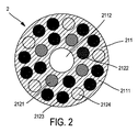
図1〜図3に示されているように、検出ヘッド21は、本体211および本体211の長手方向において本体211内に位置する検出光ファイバの束212を有する。
As shown in FIGS. 1 to 3, the
本体211は、全体として管状の形状をしている。本体211は、金属、例えばステンレス鋼または外科的処置と適合性のある任意他の材料で作られた円筒形の壁2111および中央チャネル2112を有する。壁2111は、検出光ファイバの束212を包囲している。束212の光ファイバは、中央チャネル2112周りに分布された状態で配置されていて中央チャネル2112に実質的に平行に位置している。
The
光ファイバの束212は、光線を検出する複数のファイバ2121、すなわち、1本の励起ファイバ2122、複数の放射線トレーサ検出ファイバ2123、および複数の制御ファイバ2124を含む。
The
ファイバ2121,2122,2123は、本体211の端面2113と連結コンポーネント219との間に位置している。より正確に言えば、ファイバ2121,2122,2123の端は、表面2113と面一をなしている。
The
光線を検出するファイバ2121は、透明なファイバで構成されている。これらファイバ2121は、生物学的組織によって放出された光信号を受け取ってこれを案内するようになっている。
The
励起ファイバ2122もまた、透明なファイバで構成されている。このファイバ2122は、源30によって生じた光励起信号を生物学的組織の方向に案内してこの組織中に含まれている蛍光分子を励起するようになっている。
The
放射性トレーサ検出ファイバ2123は、閃光放射端部分2125および主要な透明部分2126を有し、閃光放射端部分2125は、例えば加熱によって主要透明部分2126に融着されている。閃光放射端部分2125は、放射性トレーサによってあらかじめマーク付けされた組織によって放出される放射性β粒子(β+粒子またはβ-粒子)と相互作用してこれら放射性β粒子を光信号に変換するようになっている。主要部分2126は、端部分2125によって放出された光信号を案内するようになっている。
The radioactive
閃光放射部分2125は、代表的には、約1mmの長さを有し、透明部分2126は、代表的には、約10cmの長さを有する。閃光放射部分2125および透明部分2126は、代表的には、1.5mmオーダの直径を有する。
制御ファイバ2124は、制御ファイバ2124がβ粒子に対してブラインドに(不感に)されていることを除き、放射性トレーサ検出ファイバ2123と同一である。より正確に言えば、制御ファイバ2124は、本体211の端面2113の下に位置し、したがって、制御ファイバ2124の端は、約400μmの厚さを有する金属層によって遮られている。
放射性トレーサ検出ファイバ2123および制御ファイバ2124は、β+粒子の消滅後に組織によって放出される511電子ボルト(eV)のγ線に対して敏感である。このγ線は、β+粒子の検出する際のバックグラウンドノイズとなる。制御ファイバ2124により、ファイバ2123によって測定された信号からγ線を差し引く目的でγ線を定量化し、かくして、β+粒子のみに起因する信号を得ることができる。
The radioactive
γ線の正確な定量化を可能にするため、プラスチックシンチレータに代えて無機シンチレータ、例えばセリウムをドープしたルテチウムオキシオルトシリケート(LSO)を用いるのが良く、このLSOは、高い密度を有し、したがって、γ線に対して良好な検出効率を示す。 To enable accurate quantification of gamma rays, an inorganic scintillator, such as cerium-doped lutetium oxyorthosilicate (LSO), may be used in place of the plastic scintillator, which has a high density and therefore , Showing good detection efficiency for γ-rays.
検出束212の光ファイバ2121,2122,2123,2124が埋め込まれた壁2111は、これらファイバのスクリーンを構成する。このスクリーンは、ファイバを周囲光および横からまたはファイバ2123の後部を介して閃光放射部分2125に到達する場合のある寄生β粒子から隔離する。
The
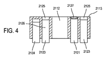
図4は、検出ヘッド21の変形例を示している。この変形例では、検出ヘッドのファイバ2121,2122は、本体211の端面2113までは延びていない。より正確に言えば、ファイバ2121,2122は、表面2113の下に位置している。検出ヘッド21は、各ファイバ2121,2122と関連した光学素子2127を有し、この光学素子は、組織から来た光を光ファイバ2121に集束させるとともにファイバ2122から来た光を組織に集束させる。各光学素子2127は、例えばマイクロレンズを含む。入射光の集束により、局所光濃度を増大させることができ、その結果、治療セットの感度を高めることができる。加うるに、マイクロレンズにより組織から光を集めることにより、治療セットの空間分解能が向上する。
FIG. 4 shows a modification of the
術中プローブ2は、このプローブを用手切除ツールに取り付ける締結具を更に有する。
The
術中プローブ2は、光検出ユニット29および伝送器31を更に有する。
The
光検出ユニット29は、複数の光検出器311を含み、この光検出ユニットは、電力信号を各光検出器311に供給するバッテリ60を有する。このバッテリ60は、検出ヘッド内に配置されるのが良い。変形例として、検出ヘッドは、バッテリを含む外部電源に接続される。変形例として、バッテリは、検出ヘッド内には設けられない。
The
各光検出器311は、束212の少なくとも1本のファイバ2121または2123または2124に結合される。
Each
各光検出器311は、これが受け取る光信号を単一ピクセルを表す電気信号に変換するようになっている。したがって、光検出ユニット29は、光検出ユニット29内に設けられた多くの光検出器311と同数のピクセルを生じさせる。
Each
各光検出器311は、シリコン光電子増倍管(SiPM)であるのが良く、これは、極めてコンパクトな検出器である。
Each
伝送器31は、光検出ユニット29によって生じた電気信号を受け取り、そしてこれら電気信号によって伝達される情報を分析機器に伝送するようになっている。
Transmitter 31 is adapted to receive the electrical signals generated by
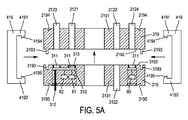
図5Aおよび図5Bは、プローブ2の第1の実施形態を概略的に示している。
FIGS. 5A and 5B schematically show a first embodiment of the
この実施形態では、術中プローブ2は、検出ヘッドに連結可能な取り外し可能部品を含む。
In this embodiment, the
取り外し可能部品は、連結コンポーネント319、光検出ユニット29および伝送器31を含む。
The removable parts include the
連結コンポーネント219,319は、検出ヘッド21の検出光ファイバ束212と取り外し可能部品の光検出ユニット29の接続を可能にするようになっている。
The connecting
図5Aでは、連結コンポーネント219,319は、互いに取り外される。
In FIG. 5A, the
連結コンポーネント219は、検出ファイバ2121,2122,2123,2124が埋め込まれた本体2191を有する。本体2191は、平らな連結表面2192を有する。ファイバ2121,2122,2123,2124の端は、連結表面2192と面一をなしている。
The
同様に、連結コンポーネント319は、少なくとも1本の伝送ファイバ3122が埋め込まれた本体3191を有する。本体3191は、平らな連結表面3192を有する。光検出器311は、連結表面3192と面一をなしている。その上、各伝送ファイバ3122の端は、平らな連結表面3192と面一をなしている。
Similarly,
本体2191は、連結表面2192から突き出た連結スタッド2193を有する。本体3191は、連結表面3192から後へ延びる連結オリフィス3193を有する。スタッド2193は、連結コンポーネント219,319を方向付けるためにオリフィス3193中に挿入されるようになっている。加うるに、スタッド2193およびオリフィス3193は、スタッド2193がオリフィス3193中に挿入されると、連結表面2192が連結表面3192に接触するとともにファイバ2121の端がファイバ3122の端に接触してファイバを互いに連結するよう配置されている。各ファイバ2121,2122,2124の端はまた、各光検出器311の頂面に接触する。
The
プローブは、連結コンポーネント219,319を互いに係合状態に保持するようになったロックコンポーネント419を更に有するのが良い。各ロックコンポーネントは、U字形であり、各ロックコンポーネントは、2つの枝部4191,4192を有する。各枝部4191,4192はそれぞれ、各自由端部のところに、突出部4194,4195を有する。
The probe may further include a
連結コンポーネント219,319の各々は、それぞれ、切欠き2194,3195を有する。
Each of the connecting
ロックコンポーネント419は、連結コンポーネント219,319が相互係合状態にあるときにこれら連結コンポーネントを互いに抱きしめるように構成されている。この目的のため、コンポーネント219,319は、ロックコンポーネント419の枝部4191,4192相互間に挿入される。突出部4194,4195が設けられていることにより、弾性変形により枝部4191,4192の相互離隔が生じる。つぎに、突出部4194,4195は、枝部4191,4192の弾性戻りによって切欠き2194,3195中に挿入されるようになっている。
The
光検出器ユニット29の各光検出器311は、単一のファイバ2121または2123または2124に結合される。一例として、図5Aは、ファイバ2123に結合された第1の光検出器、ファイバ2121に結合された第2の光検出器、およびファイバ2124に結合された第3の光検出器を示している。
Each
この実施形態では、伝送器31は、集積回路310および伝送ケーブル312を有する。
In this embodiment, the transmitter 31 has an integrated
集積回路310は、伝送ケーブル312と光検出ユニット29との間でコンポーネント319内に埋め込まれている。図5Aおよび図5Bでは完全には見えないが、集積回路310は、光検出ユニット29の各光検出器に接続されている。
The
集積回路310は、光検出ユニット29の各光検出器によって送り出された電気信号を受け取るようになっている。受け取られた各電気信号は、この集積回路によって伝送ケーブル312の対応の導線上に送られる。かくして、伝送ケーブル312は、複数のピクセルを表す複数の電気信号を伝送することができる。
The
集積回路310は、少なくとも1つの温度センサ61(例えば、光検出器1つ当たり1つの温度センサ)および電力管理回路62を更に有するのが良い(例えば、これらに結合されるのが良い)。
各温度センサ61は、光検出器311のうちの少なくとも1つの温度を検出するようになっている。
Each
電力管理回路62は、バッテリ60および各温度センサ61に接続されている。電力管理回路62は、バッテリ60により所与の光検出器311に供給される電力信号を所与の光検出器311と関連した温度センサ61によって検出された温度に基づいて調節するようになっている。例えば、バッテリ60によって光検出器311に供給される電圧を調節すると、光検出器の挙動を経時的に安定化することができる。
The
伝送ケーブル312は、多数の導電線を有する。伝送ケーブル312は、分析機器32に接続されている。伝送ケーブル312は、代表的には、検出ヘッド21から来た電気信号を術野の外側に配置された分析機器32に送るために2メートルの長さを有する。
The
図5Bでは、連結コンポーネント219,319は、相互係合状態に置かれており、ロックコンポーネント419が連結コンポーネント219,319相互係合状態に保持している。プローブのこの構成の元で、ファイバ2123の端は、第1の光検出器と接触状態にあり、ファイバ2121の端は、第2の光検出器と接触状態にあり、ファイバ2124の端は、第3の光検出器と接触状態にある。
In FIG. 5B, the connecting
図1で理解できるように、1回使用検出ヘッド21は、切除ツール1に取り外し可能な仕方で取り付けられるようになっている。この目的のため、ツール1の切除部品12は、検出ヘッド21中に挿入されるようになっている。より正確に言えば、切除ツール1の吸引ツール1212は、吸引ツール1212の吸引端が検出ヘッド21の端面2113と面一をなすよう検出ヘッド21のチャネル2112中に挿入されるようになっている。
As can be seen in FIG. 1, the single
第2に、連結コンポーネント219,319は、検出光ファイバの束212を光検出ユニット29に光学結合するために相互係合状態に置かれるようになっている。連結コンポーネント219,319は、取り外し可能な連結コンポーネントである。これにより、容易な手作業による連結および連結解除が可能である。
Second, the
したがって、1回使用検出ヘッド21は、別のヘッドで容易に置き換え可能である。
Therefore, the single
連結コンポーネント219,319を係合させると、検出ヘッドの励起ファイバ2122が伝送ケーブル312の伝送ファイバ3122に接続される。
When the
伝送ファイバ3122は、それにより源30によって放出された励起放射線を治療されるべき組織に案内するよう第1に源30に接続され、第2に励起ファイバ2122に接続されている。
The
分析機器32は、第1の収集ユニット323、第2の収集ユニット324およびPC325を含む。
The
ファイバ2123およびファイバ2124に結合された検出器からの情報を伝達する伝送ケーブル312の導線は、第1の収集ユニット323に接続されている。
The conductor of the
第1の収集ユニット323は、前置増幅エレクトロニクス3232および増幅エレクトロニクス3233を含む。
The
前置増幅エレクトロニクス3232および増幅エレクトロニクス3233は、伝送ケーブル312によって伝送される電気信号を統合し、次にこれらを増幅するようになっている。つぎに、ユニット323は、アナログ信号をPC325に送ってこれらアナログ信号のディジタル化および処理を行うようになっている。
ファイバ2121に結合された検出器からの情報を伝達する伝送ケーブル312の導線は、第2の収集ユニット324に接続されている。
The conductor of the
第2の収集ユニット324は、第1の変換エレクトロニクスユニット3241および光子計数エレクトロニクスユニット3242を含む。
The
第1の変換エレクトロニクスユニット3241は、ディジタル信号の状態で伝送ケーブル312から受け取ったアナログ電気信号を統合し、増幅し、そして変換するようになっており、その目的は、USBケーブル3243を介するPC325への直接伝送を可能にすることにある。
The first
光子計数エレクトロニクスユニット3242は、伝送ケーブル312によって運ばれる電気パルスに基づいて蛍光光子を計数してこれら蛍光光子の通過時間を測定するのに適している。通過時間は、源30によって組織の励起時間に対して測定される。
The photon
光子計数ユニット3242は、例えばUSBケーブルを介してPC325に接続されており、その目的は、光子計数ユニットによって計数されるとともに測定されたデータをPC325に直接伝送することができるようにすることにある。
The
PC325は、ディジタル化・計算ユニット3251およびディスプレイスクリーン3252を有する。ディジタル化・計算ユニット3251は、ユニット323,324によって生じた信号を受け取ってこれらを処理するようになっている。ディジタル化・計算ユニット3251はまた、ディスプレイスクリーン3252を制御するようになっている。
The
つぎに、説明したばかりの外科的治療セットの使用および作用について説明する。 The use and operation of the just described surgical treatment set will now be described.
手術前に、外科医は、手術創および治療されるべき腫瘍のタイプに適した検出ヘッド21を選択する。
Prior to surgery, the surgeon selects a
外科医は、吸引ツール1212を検出ヘッド21のチャネル2112中に挿入することによって検出ヘッド21を切除ツール1に取り付ける。
The surgeon attaches
つぎに、外科医は、連結コンポーネント219,319によってファイバ束212,312を互いに接続する。
Next, the surgeon connects the
手術の際、外科医は、腫瘍の目に見える部分の切除を実行する。 During surgery, the surgeon performs a resection of the visible portion of the tumor.
つぎに、外科医は、プローブ2の端を手術創中に挿入する。より正確に言えば、外科医は、検出ヘッド21の端面2113が治療されるべき組織区域に向いた状態で位置決めされるようプローブ2を位置決めする。外科医は、検出ヘッド21によって手術創を脇へどけて検出ヘッド21を複数の連続した位置に位置決めする。ヘッド21の各位置について、外科医は、端面2113に向いた組織区域から放出される信号のマッピングを作る。検出ヘッド21の各位置について、マッピングの収集時間は、数秒を超えない。
Next, the surgeon inserts the end of the
術中プローブにより、最初に、粒子放出放射性腫瘍状トレーサを検出することができる。 An intraoperative probe can first detect a particle-emitting radioactive tumor-like tracer.
組織野によって放出されたβ粒子がファイバのうちの1本2123によって受け取られると、ファイバ2123の閃光放射部分2125は、光信号(パルス)を発生させ、この光信号は、検出ファイバ2123の透明な部分2126によって案内される。
When the beta particles emitted by the tissue area are received by one of the
光信号は、対応の光検出器に案内される。この光検出器は、振幅が光信号の強度に比例する電気信号(電気パルス)を発生させ、この電気信号は、ピクセルを表す。 The light signal is guided to a corresponding light detector. The photodetector generates an electrical signal (electrical pulse) whose amplitude is proportional to the intensity of the optical signal, the electrical signal representing a pixel.
この電気信号は、集積回路310を介して伝送ケーブル312の対応の導線に伝送され、この伝送ケーブルは、この電気信号を収集ユニット323に送る。
The electrical signal is transmitted via integrated
収集ユニット323は、β粒子またはガンマ線によって影響を受けたファイバ2123と関連している数および閃光放射部分2125内に堆積したエネルギーを供給する。収集ユニット323は、ファイバ2123に結合されている光検出器311によって生じた電気信号を増幅するとともにこれらをディジタル化し、そして増幅した信号をディジタル化・計算ユニット3251に送る。
The
加うるに、制御ファイバ2124は、組織によって生じたγ線にのみ敏感である。
In addition,
所与の制御ファイバ2124が第2の光信号を別の光検出器に案内する。この光検出器は、第2の電気信号(電気パルス)を発生させ、この第2の電気信号は、第2の光信号の強度に比例していて別のピクセルを表示する。
A given
第2の電気信号はまた、伝送ケーブル312の専用導線によって収集ユニット323に送られる。
The second electrical signal is also sent to the
組織中のβ+粒子の消滅の結果として生じるγ線は、手術創中の腫瘍状病変の存在場所を突き止めるプロセスのためのバックグラウンドノイズとなる。これら信号は、事実、β+トレーサの領域から来る場合があり、これら信号は、このβ+トレーサの取り付けに対して特異性がありまたは特異性のない領域から来る場合があり、これら領域は、プローブによって分析される組織区域から極めて遠くに位置する。 The γ-rays resulting from the disappearance of β + particles in the tissue provide background noise for the process of locating the tumorous lesion in the surgical wound. These signals may in fact come from the region of the β + tracer, and these signals may come from regions that are specific or non-specific for the attachment of this β + tracer, It is located very far from the tissue area analyzed by the probe.
γ信号をβ+信号から区別するため、外科的処置セットは、以下の特性を有する。 To distinguish γ signals from β + signals, the surgical procedure set has the following characteristics:
第1の特徴によれば、ファイバ2123の閃光放射部分2125は、高エネルギーγ線に対してそれほど敏感ではないプラスチック材料で作られている。事実、プラスチック材料は、低密度のものである(典型的には、1.05g/cm3であり、このプラスチック材料は、原子数の低い(炭素については多くとも6)元素で構成される)。かくして、18Fのオンオフ源から0.1mmまでのところに配置された直径2mm長さ1mmの閃光放射プラスチックファイバの模擬γ効率は、同じ構成では、マイクロキュリー当たり毎秒当たり1.7×104cps/μCiのβ+効率と比較して、マイクロキュリー当たり毎秒当たり約300回の衝突分(約300cps/μCi)である。
According to a first feature, the
しかしながら、脳腫瘍の治療の場合、この放射線は、脳全体から来る場合がある。したがって、β+信号に対するγバックグラウンドノイズの貢献の度合いは、閃光放射部分を構成するプラスチック材料の固有の低い敏感性にもかかわらず、極めて高くなる場合がある。 However, in the treatment of brain tumors, this radiation can come from the whole brain. Thus, the contribution of gamma background noise to the β + signal can be quite high, despite the inherent low sensitivity of the plastic material that makes up the flash emitting portion.
第2の特徴によれば、ディジタル化・計算ユニット3251は、閃光放射部分と相互作用した粒子のエネルギーに応じてこれが受け取る信号を選択するようになっている。事実、閃光放射部分と相互作用したγ線のエレクトロスペクトルの理論的研究結果の示すところによれば検出されたγ線のうちの40%は、0〜1000kVのエネルギーを発生させ、他方、β+粒子のエネルギー分布状態は、0〜500keVである。
According to a second feature, the digitizing and calculating
したがって、ディジタル化・計算ユニット3251は、エネルギーが50〜100キロエレクトロンボルト(keV)のしきい値よりも高い信号のみを選択するようになっている。
Accordingly, digitizing and calculating
第3の特徴によれば、各放射性トレーサ検出ファイバ2123は、制御ファイバ2124と関連している。制御ファイバ2124は、γ線に対して敏感であるが、β+粒子に対しては敏感ではない。ユニット3251は、放射性トレーサ検出ファイバ2123によって生じた信号に対応する計数から関連の制御ファイバ2124によって生じた信号に対応したγ計数を差し引くようになっていて、その目的は、β+信号だけの測定値を得ることにある。
According to a third feature, each radioactive
この点に関して注目されるように、数本の放射性トレーサ検出ファイバ2123がβ粒子に対して敏感な表面2113の部分を最適化するよう単一の制御ファイバ2124と関連するのが良い。
As noted in this regard, several radioactive
ディジタル化・計算ユニット3251は、検出ヘッド21のファイバ2123のところでの放射線トレーサ濃度測定値に対応したパルスの計数を健常な組織だけで構成された手術創の区域内であらかじめ測定された基準計数と比較するようになっている。
The digitizing and calculating
測定計数と基準計数の差がしきい値標準偏差よりも大きい(例えば、3超)の場合、ユニット3251は、組織野を腫瘍状であると識別することになる。
If the difference between the measured count and the reference count is greater than the threshold standard deviation (eg, greater than 3),
ディジタル化・計算ユニット3251は、スクリーン3252に指令を出してこのスクリーンが各ファイバ2123によって検出されたβ粒子の数を示す組織野のマッピングを表示するようになっている。
The digitizing /
かくして、外科医は、スクリーン3252上の治療後の組織区域のイメージをリアルタイムで見ることができ、このイメージは、検出ヘッド21のファイバ2123のところでの放射線トレーサの濃度の分布状態を示している。
Thus, the surgeon can see in real time an image of the post-treatment tissue area on the
術中プローブはまた、蛍光光学法によって腫瘍状組織検出のために用いられる。 Intraoperative probes are also used for tumorous tissue detection by fluorescence optics.
かくして、透明なファイバ2121は、組織中に存在する蛍光分子がファイバ2122によって組織に伝えられた光励起信号によって励起された後、かかる蛍光分子によって放出される蛍光放射線を受け取る。蛍光光線を含む光信号は、透明なファイバ2121により、ファイバの近位端と光検出器との間に配置されたフィルタ313を通って光検出ユニットの光検出器311に案内される。フィルタ313は、光ファイバ2121によって案内された光信号から特定の波長または特定の波長範囲を選択して濾波後の蛍光信号を生じさせ、この場合、光検出器は、濾波後の信号を受け取るよう配置されている。
Thus, the
光検出器は、振幅が濾波後の蛍光信号の強度に比例する電気信号を発生させる。この電気信号は、最初に、収集ユニット324によって受け取られる。
The photodetector generates an electrical signal whose amplitude is proportional to the intensity of the filtered fluorescence signal. This electrical signal is first received by the
ユニット3241は、対応の蛍光の強度および蛍光を集めたファイバ2121と関連している数を供給する。変換エレクトロニクスユニット3241は、濾波後の蛍光信号をディジタル化し、そしてディジタル化した信号をディジタル化・計算ユニット3251に伝送する。ユニット3242は、濾波後の蛍光信号の光子の数を供給するとともにこれらの通過時間を測定し、次に、ユニット3242は、計数したデータおよび測定した時間を直接ユニット3251に送る。
ディジタル化・計算ユニット3251は、ファイバ2121によって検出された放射線の係数を健常な組織だけで構成された手術創の区域内であらかじめ測定された基準計数と比較するようになっている。これら係数相互間の差が所定のしきい値よりも大きい場合(係数は、例えば基準係数に対して3超の標準偏差を有する)、ユニット3251は、組織野を腫瘍状であると識別することになる。
The digitizing and calculating
加うるに、ディジタル化・計算ユニット3251は、ファイバ2121によって検出された蛍光スペクトルの選択されかつ調節可能な波長範囲内の蛍光放射線の強度を健常な組織だけで構成された手術創の区域内であらかじめ測定された基準強度と比較するようになっている。例えば、スペクトルの「赤色」貢献度(600〜700nmの波長)が基準スペクトルに対して100%を超えて大きい場合、ユニット3251は、この組織野を腫瘍状であると識別することになる。
In addition, the digitizing and
加うるに、ディジタル化・計算ユニット3251は、ユニット3242の信号からの蛍光の減衰時間を計算し、そしてこれらを健常な組織だけで構成された手術創の区域内であらかじめ測定された基準減衰時間と比較するようになっている。測定減衰時間のうちの少なくとも1つが基準時間に対して50%だけ大きい標準偏差を有する場合、ユニット3251は、この組織野を腫瘍状であると識別することになる。
In addition, the digitizing and calculating
最後に、ディジタル化・計算ユニット3251は、装置3233,3241,3242,3223によって生じた種々のデータを組み合わせ状態で処理するようになっている。腫瘍状組織の識別は、かくして、相補データに基づいており、これにより、互いに異なるデータの独立した使用による場合よりも信頼性の高い結果が得られる。
Finally, the digitizing / calculating
特に、腫瘍状区域を示す同一の組織野からの互いに異なる独立パラメータに基づく数個の測定値に関し、しかしながら、基準区域について指定されたしきい値を超えない状態で、ユニット3251は、この区域を腫瘍状であると識別することになる。有意な測定値(3を超える標準偏差)が確認されない逆の場合、または有意な測定値が別の測定値と矛盾する場合、ユニット3251は、互いの組織の切除を提案することはない。
In particular, for several measurements based on different independent parameters from the same tissue field indicating the tumorous area, but without exceeding the threshold value specified for the reference area, the
処理ユニット3251は、スクリーン3252が各々組織野を表す数個の二次元グラフ図を表示するようスクリーン3252を制御する。第1のグラフは、各ファイバ2123のところのβトレーサの計数を示している。
The
ユニット3251は、スクリーン3252に指令を出して放射線の波長に従って蛍光放射線の強度を表す第2のグラフを提供するのが良い。事前に、外科医は、波長窓を選択しているであろうし、この第2のグラフでは、スクリーン3251は、波長が外科医によって選択された窓の下限と上限との間にあるファイバ2121のところの蛍光放射線の強度だけを表示することになる。
ユニット3251はまた、スクリーン3252がファイバ2121のところで検出された蛍光分子によって検出される放射線の減衰時間を表示する第3のグラフを表示するようスクリーン3252を制御する。
かくして、外科医は、測定した強度およびスクリーン3252上の治療後の組織区域に特有のパラメータの空間部分布状態の数個のマッピングをリアルタイムで視認することができる。
Thus, the surgeon can see in real time several mappings of the measured intensity and spatial distribution of parameters specific to the treated tissue area on the
スクリーン3252は、数個の測定後のマッピングと互いに重ね合わされたマッピングを同時に表示することができる。
The
スクリーン3252はまた、個別的に行われた測定の結果をまとめて示す表を表示するとともに結論を外科医に提供することができる。
The
スクリーン3252によって表示された1つまたは複数のマッピングに従って、外科医は、切除ツール1によって組織区域を切除するかどうかを決断することができる。
According to the one or more mappings displayed by the
プローブ2の第2の実施形態が図6に示されている。
A second embodiment of the
この第2の実施形態は、光検出ユニット29、フィルタ313、集積回路310および伝送器31が検出ヘッドに連結可能な取り外し可能な部品内ではなく検出ヘッド内に埋め込まれているという点で図5Aおよび図5Bに示された第1の実施形態とは異なっている。
This second embodiment differs from FIG. 5A in that the
プローブ2の第3の実施形態が図7に示されている。
A third embodiment of the
この第3の実施形態は、多くの光検出器を同一のファイバ、例えばファイバ2123および/またはファイバ2124に結合できるという点で第2の実施形態とは異なっている。
This third embodiment differs from the second embodiment in that many photodetectors can be coupled to the same fiber, for example,
図7に示されている特定の実施例では、2つの光検出器311がファイバ2123の遠位端と接触関係をなしてプローブの本体内に配置され、他の2つの光検出器311がファイバ2124の近位端と接触関係をなしてプローブの本体内に配置される。各光検出器は、ピクセルを表す別個の電気信号を生じさせる。
In the particular embodiment shown in FIG. 7, two
かかる構成は、光検出器の大部分がノイズ、いわゆる「ダークノイズ」を発生させるという点で有利である。2つの別々の光検出器によって生じたダークノイズを相関させることがないので、これらダークノイズの影響を除くには、2つの光検出器によって生じた両方の電気信号を同時に検出するのが良い。かくして、検出しきい値は、極めて低いのが良く、ベータ感度が増大する。 Such an arrangement is advantageous in that most of the photodetectors generate noise, so-called "dark noise". Since the dark noise generated by two separate photodetectors is not correlated, it is better to detect both electric signals generated by the two photodetectors at the same time in order to eliminate the influence of these dark noises. Thus, the detection threshold may be very low, increasing the beta sensitivity.
当然のことながら、2つ以上の光検出器をたった1本のファイバに結合することもまた、第1の実施形態に含まれるのが良い。 Of course, coupling two or more photodetectors to only one fiber may also be included in the first embodiment.
プローブ2の第4の実施形態が図8に示されている。
A fourth embodiment of the
第3の実施形態の場合と同様、複数の光検出器を同一のファイバに結合するのが良い。しかしながら、この複数個の光検出器のうちで少なくとも1つの光検出器は、同じファイバの近位端に接触するよう配置され、これに対し、他の少なくとも1つの光検出器は、同じファイバの側面に接触するよう配置される。この構成により、複数の光検出器による光の収集具合が向上する。 As in the case of the third embodiment, it is preferable to couple a plurality of photodetectors to the same fiber. However, at least one of the plurality of photodetectors is arranged to contact the proximal end of the same fiber, while at least one other photodetector is of the same fiber. It is arranged to contact the side. With this configuration, the degree of light collection by the plurality of photodetectors is improved.
プローブ2の第5の実施形態が図9に示されている。
A fifth embodiment of the
この第5の実施形態は、検出ヘッドが光検出ユニットおよび集積回路310を有し、これに対し取り外し可能な部品が伝送ファイバ3122の一部分を含んでいるという点で第1の実施形態とは異なっている。
This fifth embodiment differs from the first embodiment in that the detection head has a light detection unit and an
各ファイバ2122および対応のファイバ3122が別々であり(第1および第5の実施形態に示されているように)または同じファイバの幾つかの部分(第2、第3および第4の実施形態に示されているように)であるのが良いことに注目することができる。
Each
上述した治療セットの全ての変形例では、伝送器31は、分析機器に接続されたケーブルを有する。 In all variants of the treatment set described above, the transmitter 31 has a cable connected to the analytical instrument.
「ワイヤレス実施形態」と呼ばれる図10に示された別の実施形態では、伝送器は、集積回路310に接続されたワイヤレス通信モジュール314を有する。ワイヤレス通信モジュール314は、集積回路310から受け取った電気信号を無線信号に変換するようになっている。ワイヤレス実施形態では、光源30は、検出ヘッド内に設けられるのが良い。この実施形態では、光源30は、少なくとも1つのLEDを含むのが良い。光源30は、3D位置をコンピュータ計算するために少なくとも3つのLEDを含むのが良い。
In another embodiment shown in FIG. 10 called “wireless embodiment”, the transmitter has a
分析機器は、無線信号を受け取ってこれを電気信号に変換し、そして電気信号をPC325に伝送するようになったワイヤレス通信モジュール3140を有する。
The analytical instrument has a
両方のワイヤレス通信モジュールは、種々のワイヤレス通信プロトコル、Wi‐Fi、ブルートゥース(Bluetooth)(登録商標)などをサポートすることができる。 Both wireless communication modules can support various wireless communication protocols, Wi-Fi, Bluetooth®, and the like.
つぎに図11を参照すると、プローブは、プローブの3D位置を位置分析機器(例えば、分析機器32または別の機器)に伝送する位置伝送器72を更に有するのが良い。
Referring now to FIG. 11, the probe may further include a
別の実施形態では、位置伝送器は、ルミネッセント源、例えばLEDを有し、位置分析機器は、ルミネッセント源によって放出された光を示すイメージを捕捉するカメラおよび捕捉したイメージに基づいてプローブの位置を推定するプロセッサを有する。 In another embodiment, the position transmitter has a luminescent source, e.g., an LED, and the position analysis instrument has a camera that captures an image showing the light emitted by the luminescent source and a position of the probe based on the captured image. It has a processor to estimate.
さらに別の実施形態では、ルミネッセント源に代えて、プローブの表面に付けられるとともに位置分析機器によって知られる所定のマーカが用いられる。したがって、プロセッサは、カメラによって捕捉されたイメージ中のマーカのパターンを検出してこのパターンに基づいてプローブの位置を推定することができる。 In yet another embodiment, the luminescent source is replaced by a predetermined marker attached to the surface of the probe and known by the position analysis instrument. Thus, the processor can detect the pattern of the markers in the image captured by the camera and estimate the position of the probe based on this pattern.
位置センサ71は、検出ヘッド内に配置されても良くまたは検出ヘッドに連結可能な取り外し可能なナビゲーションモジュール内に配置されても良い。
The
位置センサ71は、上述の任意の実施形態に設けられるのが良い。
The
プローブの3D位置確認により、切除ツールの位置および光ファイバによって生じた放射性または蛍光信号の分布状態のイメージを正確に相関させることができる。実際には、検出光ファイバの空間内での3D位置が位置センサにより測定されるので、光ファイバによって検出される放射性および/または蛍光信号から識別された腫瘍状組織の真の位置もまた求められる。かくして、外科医は、切除ツールの先端部を腫瘍野に完全に接触させてこれらを除去することができる。また、3D位置確認により、プローブによって既に動いた空間内の位置を記録することによって全体的な外科的創を探ったかどうかをチェックすることができる。 The 3D localization of the probe allows an accurate correlation between the position of the ablation tool and the distribution of the radioactive or fluorescent signal generated by the optical fiber. In practice, since the 3D position in space of the detection optical fiber is measured by the position sensor, the true position of the tumorous tissue identified from the radioactive and / or fluorescent signals detected by the optical fiber is also determined. . Thus, the surgeon can remove the excision tools by bringing the tips of the resection tools into full contact with the tumor fields. Also, with 3D localization, it is possible to check whether the entire surgical wound has been explored by recording the position in the space already moved by the probe.
検出ヘッド21内における光ファイバの本数および配置状態は、種々の外科的プロトコルの制約条件を満たすよう容易に変更可能であることが注目されよう。
It will be noted that the number and arrangement of optical fibers in the
種々の仕様(コンパクトさ、感度、分解能など)を満たすある範囲の互換性のある検出ヘッド21を提供することによってプローブ2をより汎用性にすることができる。
The
かくして、検出ヘッドを組織中に存在する蛍光分子の検出のために透明なファイバ2121および1本の励起ファイバ2122のみ設けることが可能である。
Thus, it is possible to provide a detection head with only a
また、1本の放射線βトレーサ検出ファイバ2123および1本の制御ファイバ2124だけを有する検出ヘッドを提供することが可能である。この種の検出ヘッドは、プローブに極めてコンパクトさを必要とする外科的処置、例えば内視鏡検査または生検下の切除手技に特に適している。
Further, it is possible to provide a detection head having only one radiation β
他の極端な場合、放射性トレーサの空間分布状態および2平方センチメートル(cm2)のオーダの視野における光線のマッピングを実施するために用いられる検出ファイバ2121,2123の数個の同心層を有する検出ヘッドを提供することが可能である。この種の検出ヘッドは、手術創の迅速な診断的切開または放射性トレーサの高い非特異性固定によって制限される手術を必要とする外科的処置に適している。
At the other extreme, a detection head having several concentric layers of
計数プローブとは対照的に、治療されるべき組織野のマッピングを作成するオプションにより、事実、バックグラウンドノイズに特有の腫瘍性信号を識別し、したがってSN比(信号対雑音比)を向上させることができ、それにより、SN比は、病変の周りの組織内に定着しているトレーサの多様性によって悪い影響を受ける場合がある。 In contrast to counting probes, the option to create a mapping of the tissue area to be treated, in fact, identifies oncogenic signals specific to background noise and thus improves the signal-to-noise ratio (signal-to-noise ratio) Therefore, the signal-to-noise ratio may be adversely affected by the diversity of the tracers that are established in the tissue around the lesion.
上述したこれら2つの極端な形態相互間において、本数および位置決めの面でファイバの中間配置状態を有する検出ヘッドもまた想定できる。 Between these two extremes mentioned above, detection heads having an intermediate arrangement of fibers in terms of number and positioning are also conceivable.
有利には、各ファイバから来た単一の信号の状態のデータを組み合わせるとともに合計すること可能である。次に、プローブが治療されるべき区域のための良好な感度を有するような仕方でこの合計を単一のモノピクセル検出器として用いる。 Advantageously, it is possible to combine and sum the data of the state of a single signal coming from each fiber. This sum is then used as a single monopixel detector in such a way that the probe has good sensitivity for the area to be treated.
上述した治療セットは、放射性トレーサの濃度および蛍光分子分布状態の同時測定を可能にする。この関連付けを用いてこれら互いに異なる測定により提供される組織学的、代謝性および分子データの相補性を増大させ、かくして腫瘍の術中検出の効率を高める。 The treatment set described above allows simultaneous measurement of radiotracer concentration and fluorescent molecule distribution. This association is used to increase the complementarity of the histological, metabolic and molecular data provided by these different measurements, thus increasing the efficiency of intraoperative detection of tumors.
上述したプローブは、小さな寸法のものでありかつ操作が容易であり、かくして手術創の狭い領域(例えば脳腫瘍に関して3〜5cmのオーダの腔)への接近が可能である。 The probe described above is of small size and easy to operate, thus allowing access to a small area of the surgical wound (e.g. a cavity on the order of 3-5 cm for a brain tumor).
加うるに、プローブは、切開されるべき組織の区域の存在場所の正確かつ迅速な突き止めを可能にする。 In addition, the probe allows for an accurate and quick localization of the area of tissue to be dissected.
事実、切除ツールとの結合により、外科医は、切除ツールの近くに位置する組織野のマッピングをリアルタイムで観察することができ、したがって、最初にこれを区切って単一手技で腫瘍状組織の正確かつ迅速な切除を実施することができる。 In fact, the coupling with the resection tool allows the surgeon to observe in real time the mapping of the tissue field located near the resection tool, thus first separating it into a single procedure to accurately and accurately map the tumorous tissue. Rapid excision can be performed.
最後に、プローブは、先行技術の術式の場合よりも腫瘍の特定の検出を可能にする。事実、数種類のトレーサの検出を組み合わせることにより、治療されるべき組織の性状に関する正確かつ確実な情報を提供することができる。 Finally, the probe allows for a more specific detection of the tumor than in prior art procedures. In fact, the combination of the detection of several types of tracers can provide accurate and reliable information on the nature of the tissue to be treated.
光励起信号に応答して組織野中の蛍光分子によって放出される信号を測定する本発明のプローブは、有利にはまた、組織による光励起信号の反射から得られる光信号を測定する。 The probe of the present invention, which measures the signal emitted by fluorescent molecules in a tissue field in response to the photoexcitation signal, advantageously also measures the optical signal resulting from the reflection of the photoexcitation signal by the tissue.
上述の改造例では、極めて小さな直径のマイクロ光ファイバの束が当然のことながら上述した各光ファイバに取って代わることができる。 In the above modification, a bundle of micro optical fibers of very small diameter can of course replace each optical fiber described above.
Claims (18)
検出ヘッドと、
組織野中の放射性トレーサおよび蛍光分子のうちの少なくとも一方によって放出される信号の受信および案内のための少なくとも1本の光ファイバと、
前記光ファイバによって案内された前記信号を電気信号に変換する少なくとも1つの光検出器と、
前記電気信号によって伝達される情報を分析機材に伝送する伝送器と、
前記信号を放出している前記組織野から組織の一部分を除去するために前記用手切除ツールを適合させるよう前記プローブを前記用手切除ツールに取り付ける締結具とを有し、
前記検出ヘッドに連結可能な取り外し可能な部品を更に有し、前記検出ヘッドは、前記光ファイバを有し、前記取り外し可能な部品は、前記伝送器を含み、
前記検出ヘッドは、第1の連結面を有し、
前記取り外し可能な部品は、第2の連結面を有し、
前記第1および前記第2の連結面は、前記取り外し可能な部品が前記検出ヘッドに連結されると、前記光ファイバの端および前記光検出器に接触するよう配置されており、
前記光ファイバの前記端は、前記第1の連結面と面一をなし、前記光検出器は、前記第2の連結面と面一をなしている、術中プローブ。 An intraoperative probe for guiding a manual resection tool,
A detection head,
At least one optical fiber for receiving and guiding signals emitted by at least one of a radioactive tracer and a fluorescent molecule in a tissue field;
At least one photodetector for converting the signal guided by the optical fiber to an electrical signal;
A transmitter for transmitting information transmitted by the electric signal to the analysis equipment,
Possess a fastener attaching said probe so as to adapt the use hand resection tool to remove a portion of tissue from the tissue field which releases the signal to the for hands excision tool,
Further comprising a removable component connectable to the detection head, the detection head having the optical fiber, the removable component including the transmitter,
The detection head has a first connection surface,
The removable component has a second coupling surface;
The first and second connection surfaces are arranged to contact an end of the optical fiber and the photodetector when the removable component is connected to the detection head;
An intraoperative probe , wherein the end of the optical fiber is flush with the first coupling surface, and the photodetector is flush with the second coupling surface .
第2の光信号を発生させて案内するようベータ放射性粒子に対して不敏感性にされた制御ファイバのうちの一方である、請求項12記載のプローブ。 The same optical fiber, the optical fiber having the flash radiation portion adapted to generate a first optical signal interact with released gamma and beta radioactive particles by radioactive tracer in said tissue, and the 13. The probe of claim 12 , wherein one of the control fibers is made insensitive to beta radioactive particles to generate and guide the two optical signals.
前記少なくとも2つの光検出器のうちの第2の光検出器は、前記同一の光ファイバの側と接触状態にある表面を有する、請求項12記載のプローブ。 A first photodetector of the at least two photodetectors has a surface in contact with an end of the same optical fiber;
13. The probe of claim 12 , wherein a second one of the at least two light detectors has a surface in contact with a side of the same optical fiber.
前記組織が前記信号を反射するか、
前記組織中の前記蛍光分子が蛍光信号を放出するかのうちの少なくとも一方が行われるようになった少なくとも1本の透明な光ファイバを有する、請求項1記載のプローブ。 Sending an excitation signal to the tissue, wherein the tissue reflects the signal,
The probe according to claim 1, comprising at least one transparent optical fiber adapted to at least one of the fluorescent molecules in the tissue emitting a fluorescent signal.
Applications Claiming Priority (3)
| Application Number | Priority Date | Filing Date | Title |
|---|---|---|---|
| US14/581,627 US9775573B2 (en) | 2005-09-13 | 2014-12-23 | Peroperative sensing head adapted to be coupled to an ablation tool |
| US14/581,627 | 2014-12-23 | ||
| PCT/EP2015/081188 WO2016102681A1 (en) | 2014-12-23 | 2015-12-23 | Peroperative sensing head adapted to be coupled to an ablation tool |
Publications (2)
| Publication Number | Publication Date |
|---|---|
| JP2018509945A JP2018509945A (en) | 2018-04-12 |
| JP6641375B2 true JP6641375B2 (en) | 2020-02-05 |
Family
ID=55072638
Family Applications (1)
| Application Number | Title | Priority Date | Filing Date |
|---|---|---|---|
| JP2017534255A Active JP6641375B2 (en) | 2014-12-23 | 2015-12-23 | Intraoperative detection head now coupled to ablation tool |
Country Status (3)
| Country | Link |
|---|---|
| EP (1) | EP3236836B1 (en) |
| JP (1) | JP6641375B2 (en) |
| WO (1) | WO2016102681A1 (en) |
Families Citing this family (1)
| Publication number | Priority date | Publication date | Assignee | Title |
|---|---|---|---|---|
| GB201118773D0 (en) * | 2011-10-31 | 2011-12-14 | Univ Bristol | Probe |
Family Cites Families (3)
| Publication number | Priority date | Publication date | Assignee | Title |
|---|---|---|---|---|
| US5983125A (en) * | 1993-12-13 | 1999-11-09 | The Research Foundation Of City College Of New York | Method and apparatus for in vivo examination of subcutaneous tissues inside an organ of a body using optical spectroscopy |
| WO2012157552A1 (en) * | 2011-05-18 | 2012-11-22 | コニカミノルタアドバンストレイヤー株式会社 | Probe |
| US10342416B2 (en) * | 2011-10-13 | 2019-07-09 | Koninklijke Philips N.V. | Medical probe with multi-fiber lumen |
-
2015
- 2015-12-23 JP JP2017534255A patent/JP6641375B2/en active Active
- 2015-12-23 WO PCT/EP2015/081188 patent/WO2016102681A1/en active Application Filing
- 2015-12-23 EP EP15820860.3A patent/EP3236836B1/en active Active
Also Published As
| Publication number | Publication date |
|---|---|
| WO2016102681A1 (en) | 2016-06-30 |
| EP3236836B1 (en) | 2019-07-03 |
| JP2018509945A (en) | 2018-04-12 |
| EP3236836A1 (en) | 2017-11-01 |
Similar Documents
| Publication | Publication Date | Title |
|---|---|---|
| JP4920688B2 (en) | Intraoperative sensing head adapted to be coupled to a cutting instrument | |
| US9566030B2 (en) | Optical system for detection and characterization of abnormal tissue and cells | |
| CN101959470B (en) | Biopsy guidance by electromagnetic tracking and photonic needle | |
| CN101437455B (en) | Tissue-characterization probe with effective sensor-to-tissue contact | |
| US9763744B2 (en) | Biopsy device with integrated optical spectroscopy guidance | |
| US20060241450A1 (en) | Ultrasound guided tissue measurement system | |
| US20060264745A1 (en) | Optical biopsy system with single use needle probe | |
| JP2005501586A (en) | Multi-sensor probe for tissue identification | |
| WO1999030608A1 (en) | Apparatus and method for determining tissue characteristics | |
| JP2016508768A (en) | Optical device for use with a medical imaging device | |
| JP6641375B2 (en) | Intraoperative detection head now coupled to ablation tool | |
| US9775573B2 (en) | Peroperative sensing head adapted to be coupled to an ablation tool | |
| CN110916728A (en) | Puncture biopsy method and device based on optical fiber transmission type fluorescence life guidance | |
| EP3410925B1 (en) | Optical probe for localizing and identifying a target tissue prior to harvesting a biopsy | |
| JP2010509973A (en) | Diffuse optical tomography with markers containing phosphors | |
| NL2025324B1 (en) | A Surgical Tool, System and Method for Tissue Characterisation | |
| US20110250128A1 (en) | Method for tissue characterization based on beta radiation and coincident Cherenkov radiation of a radiotracer | |
| US20100292582A1 (en) | Tissue probe with speed control |
Legal Events
| Date | Code | Title | Description |
|---|---|---|---|
| RD02 | Notification of acceptance of power of attorney |
Free format text: JAPANESE INTERMEDIATE CODE: A7422 Effective date: 20180215 |
|
| RD04 | Notification of resignation of power of attorney |
Free format text: JAPANESE INTERMEDIATE CODE: A7424 Effective date: 20180215 |
|
| A621 | Written request for application examination |
Free format text: JAPANESE INTERMEDIATE CODE: A621 Effective date: 20180926 |
|
| A977 | Report on retrieval |
Free format text: JAPANESE INTERMEDIATE CODE: A971007 Effective date: 20190614 |
|
| A131 | Notification of reasons for refusal |
Free format text: JAPANESE INTERMEDIATE CODE: A131 Effective date: 20190709 |
|
| A521 | Request for written amendment filed |
Free format text: JAPANESE INTERMEDIATE CODE: A523 Effective date: 20191008 |
|
| TRDD | Decision of grant or rejection written | ||
| A01 | Written decision to grant a patent or to grant a registration (utility model) |
Free format text: JAPANESE INTERMEDIATE CODE: A01 Effective date: 20191203 |
|
| A61 | First payment of annual fees (during grant procedure) |
Free format text: JAPANESE INTERMEDIATE CODE: A61 Effective date: 20191227 |
|
| R150 | Certificate of patent or registration of utility model |
Ref document number: 6641375 Country of ref document: JP Free format text: JAPANESE INTERMEDIATE CODE: R150 |
|
| R250 | Receipt of annual fees |
Free format text: JAPANESE INTERMEDIATE CODE: R250 |
|
| R250 | Receipt of annual fees |
Free format text: JAPANESE INTERMEDIATE CODE: R250 |