JP6634440B2 - Surgical retrieval device - Google Patents
Surgical retrieval device Download PDFInfo
- Publication number
- JP6634440B2 JP6634440B2 JP2017513146A JP2017513146A JP6634440B2 JP 6634440 B2 JP6634440 B2 JP 6634440B2 JP 2017513146 A JP2017513146 A JP 2017513146A JP 2017513146 A JP2017513146 A JP 2017513146A JP 6634440 B2 JP6634440 B2 JP 6634440B2
- Authority
- JP
- Japan
- Prior art keywords
- layer
- mesh
- loop
- strands
- loop member
- Prior art date
- Legal status (The legal status is an assumption and is not a legal conclusion. Google has not performed a legal analysis and makes no representation as to the accuracy of the status listed.)
- Active
Links
- 239000000463 material Substances 0.000 claims description 112
- 230000033001 locomotion Effects 0.000 claims description 20
- 230000005540 biological transmission Effects 0.000 claims description 16
- 239000011248 coating agent Substances 0.000 claims description 15
- 238000000576 coating method Methods 0.000 claims description 15
- 229920000642 polymer Polymers 0.000 claims description 12
- 229910001000 nickel titanium Inorganic materials 0.000 claims description 11
- HLXZNVUGXRDIFK-UHFFFAOYSA-N nickel titanium Chemical compound [Ti].[Ti].[Ti].[Ti].[Ti].[Ti].[Ti].[Ti].[Ti].[Ti].[Ti].[Ni].[Ni].[Ni].[Ni].[Ni].[Ni].[Ni].[Ni].[Ni].[Ni].[Ni].[Ni].[Ni].[Ni] HLXZNVUGXRDIFK-UHFFFAOYSA-N 0.000 claims description 11
- 238000011084 recovery Methods 0.000 claims description 8
- 229910000831 Steel Inorganic materials 0.000 claims description 7
- 239000010935 stainless steel Substances 0.000 claims description 7
- 229910001220 stainless steel Inorganic materials 0.000 claims description 7
- 239000010959 steel Substances 0.000 claims description 7
- 229910052751 metal Inorganic materials 0.000 claims description 4
- 239000002184 metal Substances 0.000 claims description 4
- 230000008602 contraction Effects 0.000 claims 2
- 239000010410 layer Substances 0.000 description 65
- 238000000034 method Methods 0.000 description 33
- 239000000853 adhesive Substances 0.000 description 21
- 230000001070 adhesive effect Effects 0.000 description 21
- -1 polyethylene terephthalate Polymers 0.000 description 15
- 229920002614 Polyether block amide Polymers 0.000 description 13
- 229920000139 polyethylene terephthalate Polymers 0.000 description 13
- 239000005020 polyethylene terephthalate Substances 0.000 description 13
- 238000010438 heat treatment Methods 0.000 description 12
- 238000005520 cutting process Methods 0.000 description 10
- 239000004677 Nylon Substances 0.000 description 9
- 229920001778 nylon Polymers 0.000 description 9
- 238000003466 welding Methods 0.000 description 7
- 229920001577 copolymer Polymers 0.000 description 6
- 238000002844 melting Methods 0.000 description 6
- 230000008018 melting Effects 0.000 description 6
- 239000012790 adhesive layer Substances 0.000 description 5
- 238000003825 pressing Methods 0.000 description 5
- XEEYBQQBJWHFJM-UHFFFAOYSA-N Iron Chemical compound [Fe] XEEYBQQBJWHFJM-UHFFFAOYSA-N 0.000 description 4
- 238000005452 bending Methods 0.000 description 4
- 239000011230 binding agent Substances 0.000 description 4
- 238000001816 cooling Methods 0.000 description 4
- 229920000747 poly(lactic acid) Polymers 0.000 description 4
- 229920001343 polytetrafluoroethylene Polymers 0.000 description 4
- 239000004810 polytetrafluoroethylene Substances 0.000 description 4
- 230000008569 process Effects 0.000 description 4
- 239000003292 glue Substances 0.000 description 3
- 239000004626 polylactic acid Substances 0.000 description 3
- 238000003860 storage Methods 0.000 description 3
- 241000156961 Coenonympha Species 0.000 description 2
- 239000004698 Polyethylene Substances 0.000 description 2
- 238000007664 blowing Methods 0.000 description 2
- 238000004891 communication Methods 0.000 description 2
- 239000004020 conductor Substances 0.000 description 2
- 229920001903 high density polyethylene Polymers 0.000 description 2
- 239000004700 high-density polyethylene Substances 0.000 description 2
- 229910052742 iron Inorganic materials 0.000 description 2
- 238000010409 ironing Methods 0.000 description 2
- 239000000314 lubricant Substances 0.000 description 2
- 210000000056 organ Anatomy 0.000 description 2
- 229920000573 polyethylene Polymers 0.000 description 2
- 229920001195 polyisoprene Polymers 0.000 description 2
- 230000000717 retained effect Effects 0.000 description 2
- 229910001285 shape-memory alloy Inorganic materials 0.000 description 2
- 239000007779 soft material Substances 0.000 description 2
- BFKJFAAPBSQJPD-UHFFFAOYSA-N tetrafluoroethene Chemical group FC(F)=C(F)F BFKJFAAPBSQJPD-UHFFFAOYSA-N 0.000 description 2
- 238000012546 transfer Methods 0.000 description 2
- 238000009966 trimming Methods 0.000 description 2
- 229920006358 Fluon Polymers 0.000 description 1
- 229920002633 Kraton (polymer) Polymers 0.000 description 1
- 229920002319 Poly(methyl acrylate) Polymers 0.000 description 1
- 239000004952 Polyamide Substances 0.000 description 1
- 239000004721 Polyphenylene oxide Substances 0.000 description 1
- 239000004809 Teflon Substances 0.000 description 1
- 229920006362 Teflon® Polymers 0.000 description 1
- 239000002253 acid Substances 0.000 description 1
- 210000001124 body fluid Anatomy 0.000 description 1
- 238000007796 conventional method Methods 0.000 description 1
- 229920003020 cross-linked polyethylene Polymers 0.000 description 1
- 239000004703 cross-linked polyethylene Substances 0.000 description 1
- 238000000354 decomposition reaction Methods 0.000 description 1
- 238000007598 dipping method Methods 0.000 description 1
- 238000001035 drying Methods 0.000 description 1
- 238000001125 extrusion Methods 0.000 description 1
- 239000012530 fluid Substances 0.000 description 1
- 230000006870 function Effects 0.000 description 1
- 238000007731 hot pressing Methods 0.000 description 1
- 230000002452 interceptive effect Effects 0.000 description 1
- 230000001678 irradiating effect Effects 0.000 description 1
- 238000004519 manufacturing process Methods 0.000 description 1
- 230000013011 mating Effects 0.000 description 1
- 230000007246 mechanism Effects 0.000 description 1
- 239000000155 melt Substances 0.000 description 1
- 150000002739 metals Chemical class 0.000 description 1
- 239000000203 mixture Substances 0.000 description 1
- 238000012986 modification Methods 0.000 description 1
- 230000004048 modification Effects 0.000 description 1
- 229920003229 poly(methyl methacrylate) Polymers 0.000 description 1
- 229920000636 poly(norbornene) polymer Polymers 0.000 description 1
- 229920000058 polyacrylate Polymers 0.000 description 1
- 229920002647 polyamide Polymers 0.000 description 1
- 229920001610 polycaprolactone Polymers 0.000 description 1
- 239000004632 polycaprolactone Substances 0.000 description 1
- 229920000570 polyether Polymers 0.000 description 1
- 229920000151 polyglycol Polymers 0.000 description 1
- 239000010695 polyglycol Substances 0.000 description 1
- 239000002861 polymer material Substances 0.000 description 1
- 239000004926 polymethyl methacrylate Substances 0.000 description 1
- 229920000098 polyolefin Polymers 0.000 description 1
- 229920001296 polysiloxane Polymers 0.000 description 1
- 229920002635 polyurethane Polymers 0.000 description 1
- 239000004814 polyurethane Substances 0.000 description 1
- 239000011148 porous material Substances 0.000 description 1
- 239000000843 powder Substances 0.000 description 1
- 230000005855 radiation Effects 0.000 description 1
- 239000011347 resin Substances 0.000 description 1
- 229920005989 resin Polymers 0.000 description 1
- 238000007665 sagging Methods 0.000 description 1
- 229920002545 silicone oil Polymers 0.000 description 1
- 239000002904 solvent Substances 0.000 description 1
- 229920003048 styrene butadiene rubber Polymers 0.000 description 1
- 229920001169 thermoplastic Polymers 0.000 description 1
- 239000004416 thermosoftening plastic Substances 0.000 description 1
- 238000009281 ultraviolet germicidal irradiation Methods 0.000 description 1
- 238000012800 visualization Methods 0.000 description 1
- 238000009941 weaving Methods 0.000 description 1
Images


Classifications
-
- A—HUMAN NECESSITIES
- A61—MEDICAL OR VETERINARY SCIENCE; HYGIENE
- A61B—DIAGNOSIS; SURGERY; IDENTIFICATION
- A61B17/00—Surgical instruments, devices or methods, e.g. tourniquets
- A61B17/22—Implements for squeezing-off ulcers or the like on the inside of inner organs of the body; Implements for scraping-out cavities of body organs, e.g. bones; Calculus removers; Calculus smashing apparatus; Apparatus for removing obstructions in blood vessels, not otherwise provided for
- A61B17/221—Gripping devices in the form of loops or baskets for gripping calculi or similar types of obstructions
-
- A—HUMAN NECESSITIES
- A61—MEDICAL OR VETERINARY SCIENCE; HYGIENE
- A61B—DIAGNOSIS; SURGERY; IDENTIFICATION
- A61B17/00—Surgical instruments, devices or methods, e.g. tourniquets
- A61B17/00234—Surgical instruments, devices or methods, e.g. tourniquets for minimally invasive surgery
-
- A—HUMAN NECESSITIES
- A61—MEDICAL OR VETERINARY SCIENCE; HYGIENE
- A61B—DIAGNOSIS; SURGERY; IDENTIFICATION
- A61B17/00—Surgical instruments, devices or methods, e.g. tourniquets
- A61B17/50—Instruments, other than pincettes or toothpicks, for removing foreign bodies from the human body
-
- A—HUMAN NECESSITIES
- A61—MEDICAL OR VETERINARY SCIENCE; HYGIENE
- A61B—DIAGNOSIS; SURGERY; IDENTIFICATION
- A61B17/00—Surgical instruments, devices or methods, e.g. tourniquets
- A61B17/00234—Surgical instruments, devices or methods, e.g. tourniquets for minimally invasive surgery
- A61B2017/00287—Bags for minimally invasive surgery
-
- A—HUMAN NECESSITIES
- A61—MEDICAL OR VETERINARY SCIENCE; HYGIENE
- A61B—DIAGNOSIS; SURGERY; IDENTIFICATION
- A61B17/00—Surgical instruments, devices or methods, e.g. tourniquets
- A61B2017/00526—Methods of manufacturing
-
- A—HUMAN NECESSITIES
- A61—MEDICAL OR VETERINARY SCIENCE; HYGIENE
- A61B—DIAGNOSIS; SURGERY; IDENTIFICATION
- A61B17/00—Surgical instruments, devices or methods, e.g. tourniquets
- A61B17/22—Implements for squeezing-off ulcers or the like on the inside of inner organs of the body; Implements for scraping-out cavities of body organs, e.g. bones; Calculus removers; Calculus smashing apparatus; Apparatus for removing obstructions in blood vessels, not otherwise provided for
- A61B17/221—Gripping devices in the form of loops or baskets for gripping calculi or similar types of obstructions
- A61B2017/2212—Gripping devices in the form of loops or baskets for gripping calculi or similar types of obstructions having a closed distal end, e.g. a loop
Description
<関連出願の相互参照>
本願は、米国特許仮出願第62/052,538号(2014年9月19日出願)、発明の名称「Method of Attaching a Mesh to a Coated Loop Member of a Surgical Snare Device」と、米国特許仮出願第62/162,786号(2015年5月17日出願)、発明の名称「Method of Attaching a Mesh to a Coated Loop Member of a Surgical Snare Device」との両方に依存し、優先権を主張する。
<Cross reference of related applications>
This application discloses U.S. Provisional Patent Application No. 62 / 052,538 (filed on September 19, 2014), entitled "Method of Attaching a Mesh to a Coated Loop Member of a Surgical Snare Device," and U.S. Provisional Application No. 62 No./162,786 (filed on May 17, 2015), claiming priority on both the invention title "Method of Attaching a Mesh to a Coated Loop Member of a Surgical Snare Device".
上述した出願の全内容を参照により本明細書に援用する。 The entire contents of the above-mentioned application are incorporated herein by reference.
本明細書は一般に、外科用器具に関するものである。より具体的には、本明細書は、体管腔から対象物を除去するために使用される外科用スネア装置であり、メッシュ又はネットが外科用スネア装置の被覆ループ部材に融着され接着された、外科用スネア装置に関するものである。 The present specification relates generally to surgical instruments. More specifically, the present description is a surgical snare device used to remove an object from a body lumen , wherein a mesh or net is fused and adhered to a coated loop member of the surgical snare device. The present invention also relates to a surgical snare device.
人体器官又は体腔から異物を把持し除去する既存の外科用装置は、機械的に作動する鉗子、機械的に作動するスネア又は機械的に作動するバスケットを備える。内視鏡による可視化、蛍光透視法による可視化及び直接可視化のもとに、これら外科用器具のそれぞれは体内に配置される。 Existing surgical devices for grasping and removing foreign objects from human organs or cavities include mechanically actuated forceps, mechanically actuated snares or mechanically actuated baskets. Under endoscopic, fluoroscopic and direct visualization, each of these surgical instruments is placed in the body.
機械的に作動するスネアは、シースに囲まれたワイヤのループに装着された軟性ウェブ部材のアセンブリを備える。ワイヤのループは、シースを越えて成形された開口部内に自動的に伸張することができ、またその結果、取り付けられ/装着されたウェブ部材を捕捉ポケットへ開く。開口部の寸法は、シースの端部を越えて前進させたワイヤの長さによって制御される。使用時に、スネアが対象物に隣接して配置された後、ワイヤをシースの端部を越えて、対象物よりも大きなループが形成されるまで前進させる。その後、ウェブ部材及びループの面が対象物を取り囲むまで、ループが位置決めされる。それから、ループ及びウェブ部材が対象物を締め付け、引掛け/捕らえるように、シースを前進させてワイヤを格納する。 A mechanically actuated snare comprises an assembly of flexible web members mounted on a loop of wire surrounded by a sheath. The wire loop can automatically extend beyond the sheath and into the formed opening, thus opening the attached / mounted web member to the capture pocket. The size of the opening is controlled by the length of wire advanced beyond the end of the sheath. In use, after the snare is positioned adjacent the object, the wire is advanced past the end of the sheath until a loop is formed that is larger than the object. The loop is then positioned until the web member and the plane of the loop surround the object. The sheath is then advanced to retract the wire so that the loop and web members clamp and catch / trap the object.
ウェブ部材は一般に、ウィービングによって及び/又はワイヤのループの周囲に沿ったクリップ若しくはリングレットを用いて、ワイヤのループに取り付けられる。ループをシース内に引き戻して対象物を締付けるときに、ウェブ部材をループに接続し一例ではウェブ部材を備える器具のストランドは、ループに沿って摺動してループの先端側端部で圧縮することがある。またウェブ部材が集まり、対象物とループの先端側端部との間に挿入することがある。また同様に、ウェブ部材をループに接合させるクリップ又はリングレットの存在は、対象物の捕獲を妨げ、より困難にし、時間がかかるものになることがある。 The web member is generally attached to the wire loop by weaving and / or using clips or ringlets around the circumference of the wire loop. When the loop is pulled back into the sheath and the object is clamped, the strands of the device that connect the web member to the loop and, in one example, include the web member, slide along the loop and compress at the distal end of the loop. There is. Also, the web members may collect and be inserted between the object and the distal end of the loop. Also, similarly, the presence of clips or ringlets that join the web members to the loops can hinder capture of the object, making it more difficult and time consuming.
ゆえに本技術分野では、手技を妨げることなく、ウェブ部材、メッシュ又はネットを外科用スネア装置のループ部材に取り付け又は接続する改良された方法が必要とされている。 Therefore, there is a need in the art for an improved method of attaching or connecting a web member, mesh or net to a loop member of a surgical snare device without interfering with the procedure.
システム、道具及び方法と関連する、以下の実施形態と実施形態の態様とを説明し図示する。当該実施形態及び態様は、例示的かつ説明的とするつもりであり、範囲を限定するものではない。本願は、多数の実施形態を開示する。 The following embodiments and aspects of embodiments are described and illustrated in connection with the systems, tools, and methods. The embodiments and aspects are intended to be illustrative and illustrative, and not limiting. This application discloses a number of embodiments.
本明細書は、メッシュをループ部材に取り付ける方法であり、前記方法は、第1材料からなるワイヤを操作して、ある形状を有するループ部材を形成するステップと、接着剤の層を前記ループ部材に当てるステップと、第2材料からなり、少なくとも部分的に前記ループ部材の周囲を覆い、一部が前記ループ部材の周囲を越えて延在する前記メッシュを、前記ループ部材の上に配置するステップと、前記メッシュを前記ループ部材の上に保持しながら、前記接着剤を紫外線照射にさらすステップと、前記メッシュを前記接着剤に接着させるステップと、前記ループ部材の周囲を越えて延在する、前記メッシュの部分を切り取るステップと、を含み、前記取り付けたメッシュと一緒の前記ループ部材は、シースの内腔に格納することによって圧縮可能であるとともに、前記シースから伸びるときに前記形状に展開可能である、方法を開示する。 The present specification is a method of attaching a mesh to a loop member, the method comprising the steps of manipulating a wire of a first material to form a loop member having a shape, and applying a layer of adhesive to the loop member. Placing the mesh on the loop member, the mesh comprising a second material and at least partially surrounding the loop member and extending partially beyond the periphery of the loop member. Exposing the adhesive to ultraviolet radiation while holding the mesh on the loop member; adhering the mesh to the adhesive; and extending beyond a periphery of the loop member. Cutting out a portion of the mesh, wherein the loop member with the attached mesh is compressed by storage in a lumen of a sheath. As well as a possible, it is deployable in the shape when extending from the sheath, discloses methods.
前記ループの前記形状を、楕円状、円形状、ティアドロップ形状、長方形状、四角形状又は多角形状のいずれか1つとすることができる。 The shape of the loop may be any one of an elliptical shape, a circular shape, a teardrop shape, a rectangular shape, a square shape, and a polygonal shape.
前記ループ部材は、前記ループ部材の中心を通る長手方向軸線に沿った第1の大きさと、前記長手方向軸線と垂直であり同様に前記ループ部材の前記中心を通る他の軸線に沿った第2の大きさとを有することができる。前記第1の大きさを前記第2の大きさよりも大きくすることができる。任意に、前記第1の大きさは30ミリメートルから70ミリメートルの範囲であり、前記第2の大きさは15ミリメートルから40ミリメートルの範囲である。あるいは、前記第1の大きさは前記第2の大きさと等しい。またあるいは、第1の大きさは前記第2の大きさよりも小さい。 The loop member has a first magnitude along a longitudinal axis passing through the center of the loop member, and a second dimension along another axis perpendicular to the longitudinal axis and also passing through the center of the loop member. And the size of The first size may be larger than the second size. Optionally, said first size ranges from 30 millimeters to 70 millimeters and said second size ranges from 15 millimeters to 40 millimeters. Alternatively, the first size is equal to the second size. Alternatively, the first size is smaller than the second size.
前記ワイヤの前記第1材料は、ニチノール、鋼又はステンレス鋼の少なくとも1つからなることができる。 The first material of the wire may comprise at least one of Nitinol, steel or stainless steel.
前記メッシュの前記第2材料は、重合体からなることができる。任意に、前記メッシュの前記第2材料は、ナイロン、ポリエチレンテレフタレート又はペバックス(登録商標)の少なくとも1つからなる。 The second material of the mesh may be made of a polymer. Optionally, said second material of said mesh comprises at least one of nylon, polyethylene terephthalate or Pebax®.
接着後、前記メッシュは前記ループ部材の中心にポーチを有することができる。 After bonding, the mesh may have a pouch at the center of the loop member.
本明細書は、軟性ワイヤのループと、前記軟性ワイヤのループ上に積層する結合材と、
前記結合材に結合されて前記軟性ワイヤのループに囲まれた開口部を有するネットを生み出すメッシュであり、前記結合材を加熱して前記結合材をわずかに接着性である状態とし、部分的に湿らせた状態とし、又は粘着性である状態として、前記結合材の上に前記メッシュの外縁を配置して、前記結合材を冷却する工程を通じて前記結合材に固定的に結合されるメッシュと、長尺本体、手元側端部及び先端側端部を含み、内部に内腔を含む管状シースと、を備える回収装置であり、前記管状シースの前記先端側端部に配置された伝達リンクの操作によって、前記軟性ワイヤのループは接合されたメッシュとともに前記内腔に格納可能であり、前記内腔から前記管状シースの前記先端側端部に存在する開口部を通じて伸張可能である、回収装置も開示する。
The present specification is a loop of a soft wire, a bonding material laminated on the loop of the soft wire,
A mesh bonded to the binder to create a net having an opening surrounded by a loop of the flexible wire, heating the binder to cause the binder to be slightly adhesive, and partially In a moistened state, or in a tacky state, an outer edge of the mesh is disposed on the bonding material, and a mesh fixedly bonded to the bonding material through a step of cooling the bonding material, A tubular sheath including a long body, a proximal end and a distal end, and having a lumen therein, and operating a transmission link disposed at the distal end of the tubular sheath. A collection device, wherein the loop of soft wire is retractable in the lumen with the joined mesh, and is extendable from the lumen through an opening in the distal end of the tubular sheath. To disclosure.
本明細書は、メッシュをループ部材に取り付ける方法であり、前記方法は、第1材料からなるワイヤを、第2材料からなる層で被覆するステップと、前記ワイヤ及び前記層を操作して、ある形状を有するとともに、前記ループ部材の中心を通る長手方向軸線に沿った第1の大きさと、前記長手方向軸線と垂直であり同様に前記ループ部材の前記中心を通る他の軸線に沿った第2の大きさとを有する、前記ループ部材を形成するステップと、第3材料からなり、少なくとも部分的に前記ループ部材の周囲を覆い、一部が前記ループ部材の周囲を越えて延在する前記メッシュを、前記ループ部材の上に配置するステップと、前記メッシュを前記ループ部材上に保持しながら前記層に熱を伝えて、前記第2材料を部分的に融解させて、前記第2材料を粘着性とし、わずかに接着性とし又は部分的に湿らせるステップと、前記メッシュを、部分的に融解し粘着性とした、前記層の前記第2材料と共に、前記ループ部材の周囲に沿って接着して、冷却時に強固に接着するステップと、前記ループ部材の前記周囲を越えて延在する、前記メッシュの部分を切り取るステップと、を含み、前記取り付けたメッシュと一緒の前記ループ部材は、シースの内腔に格納することによって圧縮可能であるとともに、前記シースから伸びるときに前記形状に展開可能であるように構成される、方法も開示する。 The present specification is a method of attaching a mesh to a loop member, the method comprising: coating a wire of a first material with a layer of a second material; and manipulating the wire and the layer. A first dimension along a longitudinal axis having a shape and passing through the center of the loop member, and a second dimension along another axis perpendicular to the longitudinal axis and also passing through the center of the loop member. Forming the loop member, the mesh comprising a third material, at least partially covering a periphery of the loop member, and partially extending beyond the periphery of the loop member. Disposing over the loop member, transferring heat to the layer while holding the mesh on the loop member to partially melt the second material, Tackifying, slightly adhering or partially moistening, bonding the mesh with the second material of the layer, partially melted and tacky, along the circumference of the loop member And firmly bonding upon cooling; and cutting out a portion of the mesh that extends beyond the perimeter of the loop member, wherein the loop member with the attached mesh comprises a sheath. A method is also disclosed that is configured to be compressible by being stored in a lumen of the housing and expandable into the shape when extended from the sheath.
前記ループ部材の前記形状を、楕円形状、円形状、ティアドロップ形状、正方形状、長方形状、四角形状又は多角形状のいずれか1つとすることができる。 The shape of the loop member may be any one of an elliptical shape, a circular shape, a teardrop shape, a square shape, a rectangular shape, a square shape, and a polygonal shape.
任意に、前記第1の大きさは前記第2の大きさよりも大きい。更に任意に、前記第1の大きさは30ミリメートルから70ミリメートルの範囲であり、前記第2の大きさは15ミリメートルから40ミリメートルの範囲である。あるいは、前記第1の大きさは前記第2の大きさと等しい。またあるいは、前記第1の大きさは前記第2の大きさよりも小さい。 Optionally, said first magnitude is greater than said second magnitude. More optionally, said first size ranges from 30 millimeters to 70 millimeters and said second size ranges from 15 millimeters to 40 millimeters. Alternatively, the first size is equal to the second size. Alternatively, the first size is smaller than the second size.
前記ワイヤの前記第1材料は、ニチノール、鋼又はステンレス鋼の少なくとも1つからなることができる。任意に、前記メッシュの前記第2材料は、重合体からなる。さらに任意に、前記メッシュの前記第2材料は、ナイロン、ペバックス又はポリエチレンテレフタレートの少なくとも1つからなる。 The first material of the wire may comprise at least one of Nitinol, steel or stainless steel. Optionally, said second material of said mesh comprises a polymer. Further optionally, said second material of said mesh comprises at least one of nylon, Pebax or polyethylene terephthalate.
任意に、前記メッシュの前記第3材料は、重合体からなる。更に任意に、前記メッシュの前記第3材料は、ニチノール又はポリエチレンテレフタレートの少なくとも一方からなる。 Optionally, said third material of said mesh comprises a polymer. Further optionally, the third material of the mesh comprises at least one of nitinol or polyethylene terephthalate.
前記層は、前記ワイヤ上を被覆することができる。 The layer can cover the wire.
任意に、前記層は前記ワイヤが挿入される中空管を含む。 Optionally, said layer comprises a hollow tube into which said wire is inserted.
任意に、前記メッシュは前記ループ部材の前記形状に近似する形状を有する。 Optionally, the mesh has a shape that approximates the shape of the loop member.
前記ワイヤを加熱することによって、前記熱を前記層の前記第2材料に伝えることができる。外部電源を用いて前記ワイヤを電気的に加熱することができる。前記メッシュを前記ループ部材上に保持しながら前記ループ部材を加熱することによって、前記熱を前記層の前記第2材料に伝えることができる。任意に、前記ループ部材を熱気にさらすことによって、前記ループ部材を加熱し、前記熱気は120℃から180℃の範囲内の温度、又は前記第2材料の融解温度の範囲内の温度を持つ。 By heating the wire, the heat can be transferred to the second material of the layer. The wires can be electrically heated using an external power supply. By heating the loop member while holding the mesh on the loop member, the heat can be transferred to the second material of the layer. Optionally, heating the loop member by exposing the loop member to hot air, wherein the hot air has a temperature in a range of 120 ° C. to 180 ° C. or a temperature in a range of a melting temperature of the second material.
任意に、前記層は0.05ミリメートルから0.6ミリメートルの範囲の厚さを有する。 Optionally, said layer has a thickness ranging from 0.05 millimeter to 0.6 millimeter.
接着後、前記メッシュは前記ループ部材の中心にポーチを有することができる。 After bonding, the mesh may have a pouch at the center of the loop member.
本明細書は、メッシュをループ部材に取り付ける方法であり、前記方法は、第1材料からなるワイヤを操作して成形されたワイヤを形成するステップと、前記成形されたワイヤを第2材料からなる層で被覆して前記ループ部材を形成するステップと、第3材料からなり、少なくとも部分的に前記ループ部材の周囲を覆い、一部が前記ループ部材の周囲を越えて延在する前記メッシュを、前記ループ部材の上に配置するステップと、前記メッシュを前記ループ部材の上に保持しながら、熱を前記層に伝えて前記第2材料を部分的に融解させるとともに、粘着性とし、わずかに接着性とし、又は部分的に湿らせるステップと、前記メッシュを部分的に融解させるとともに、粘着性とした前記層の前記第2材料に接着させるステップと、前記ループ部材の周囲を越えて延在する、前記メッシュの部分を切り取るステップと、を含み、前記ループ部材は、前記取り付けたメッシュと一緒の前記ループ部材をシースの内腔に格納することによって圧縮可能であるとともに、前記シースから伸びるときにある形状に展開可能である、方法も開示する。 The present description is a method of attaching a mesh to a loop member, the method comprising the steps of manipulating a wire made of a first material to form a formed wire, and attaching the formed wire to a second material. Coating the layer with a layer to form the loop member, the mesh comprising a third material, at least partially surrounding the loop member, and extending partially beyond the loop member. Disposing over the loop member and transferring heat to the layer to partially melt the second material while making the mesh above the loop member, making the second material tacky and slightly adhesive And partially moistening the mesh, partially melting the mesh and adhering to the second material of the layer that has been made tacky, and Trimming a portion of the mesh extending beyond the perimeter of the material, wherein the loop member is compressible by storing the loop member with the attached mesh in a lumen of a sheath. Also disclosed are methods that can be deployed into a shape when extended from the sheath.
前記ワイヤの前記形状を、楕円形状、円形状、ティアドロップ形状、正方形状、長方形状、四角形状又は多角形状のいずれか1つとすることができる。 The shape of the wire may be any one of an elliptical shape, a circular shape, a teardrop shape, a square shape, a rectangular shape, a square shape, and a polygonal shape.
前記ループ部材は、前記ループ部材の中心を通る長手方向軸線に沿った第1の大きさと、長手方向軸線と垂直であり同様に前記ループ部材の前記中心を通る他の軸線に沿った第2の大きさとを有することができる。前記第1の大きさを前記第2の大きさよりも大きくすることができる。任意に、前記第1の大きさは30ミリメートルから70ミリメートルの範囲であり、前記第2の大きさは15ミリメートルから40ミリメートルの範囲である。あるいは、前記第1の大きさは前記第2の大きさと等しい。またあるいは、前記第1の大きさは前記第2の大きさよりも小さい。 The loop member has a first magnitude along a longitudinal axis passing through the center of the loop member, and a second dimension perpendicular to the longitudinal axis and along another axis also passing through the center of the loop member. And can have a size. The first size may be larger than the second size. Optionally, said first size ranges from 30 millimeters to 70 millimeters and said second size ranges from 15 millimeters to 40 millimeters. Alternatively, the first size is equal to the second size. Alternatively, the first size is smaller than the second size.
前記ワイヤの前記第1材料は、ニチノール、鋼又はステンレス鋼の少なくとも1つからなることができる。 The first material of the wire may comprise at least one of Nitinol, steel or stainless steel.
前記層の前記第2材料は、重合体からなることができる。任意に、前記層の前記第2材料は、ナイロン、ポリエチレンテレフタレート又はペバックスの少なくとも1つからなる。 The second material of the layer can consist of a polymer. Optionally, said second material of said layer comprises at least one of nylon, polyethylene terephthalate or Pebax.
前記メッシュの前記第3材料は、重合体からなることができる。任意に、前記メッシュの前記第3材料は、ニチノール又はポリエチレンテレフタレートの少なくとも一方である。 The third material of the mesh can be made of a polymer. Optionally, said third material of said mesh is at least one of nitinol or polyethylene terephthalate.
前記層は、前記成形されたワイヤ上を被覆することができる。 The layer can cover the formed wire.
任意に、前記層は前記成形されたワイヤが挿入される中空管である。 Optionally, said layer is a hollow tube into which said shaped wire is inserted.
前記成形されたワイヤを加熱することによって、熱を前記層の前記第2材料に伝えることができる。任意に、外部電源を用いて前記成形されたワイヤを電気的に加熱する。 By heating the formed wire, heat can be transferred to the second material of the layer. Optionally, the formed wire is electrically heated using an external power source.
前記メッシュを前記ループ部材上に保持しながら前記ループ部材を加熱することによって、熱を前記層の前記第2材料に伝えることができる。任意に、前記ループ部材を熱気の熱風にさらすことによって、前記ループ部材を加熱し、前記熱気は120℃から180℃の範囲の温度、又は前記第2材料の融解温度の範囲内の温度を持つ。 Heating the loop member while holding the mesh on the loop member can transfer heat to the second material of the layer. Optionally, heating the loop member by exposing the loop member to hot air of a hot air, wherein the hot air has a temperature in a range of 120 ° C. to 180 ° C. or a temperature in a range of a melting temperature of the second material. .
任意に、前記層は0.05ミリメートルから0.6ミリメートルの範囲の厚さを有する。 Optionally, said layer has a thickness ranging from 0.05 millimeter to 0.6 millimeter.
接着後、前記メッシュは前記ループ部材の中心にポーチを有することができる。 After bonding, the mesh may have a pouch at the center of the loop member.
本明細書は、メッシュをループ部材に取り付ける方法であり、前記方法は、第1材料からなるワイヤを、第2材料からなる層で覆うステップと、前記層と一緒の前記ワイヤを操作して、ある形状を有するとともに、前記ループ部材の中心を通る長手方向軸線に沿った第1の大きさと、前記長手方向軸線と垂直であり同様に前記ループ部材の前記中心を通る他の軸線に沿った第2の大きさとを有する、前記ループ部材を形成するステップと、前記ループ部材を少なくとも部分的に基礎取付具上に配置して、前記基礎取付具内に受け込まれた複数の磁石によって保持するステップであり、保持された前記ループ部材は前記基礎取付具に形成された中空部に外接し、前記中空部はポーチ形状固定具を受け止めるように構成される、前記ループ部材を保持するステップと、第3材料からなり、少なくとも部分的に前記中空部と一緒の前記ループ部材の周囲を覆い、一部が前記ループ部材の周囲を越えて延在する前記メッシュを、前記ループ部材の上に配置するステップと、前記ポーチ形状固定具を前記メッシュの上に配置することによって、前記メッシュを中空部にプレスするステップと、前記メッシュを前記ループ部材上に保持しながら前記層に熱を伝えて、前記第2材料を部分的に融解させて、前記第2材料を粘着性とし、わずかに接着性とし又は部分的に湿らせるステップと、前記メッシュを、部分的に融解した、前記層の前記第2材料と共に、前記ループ部材の周囲に沿って溶解させて、冷却時に強固に接着するステップと、前記ループ部材の前記周囲を越えて延在する、前記メッシュの部分を切り取るステップと、を含み、前記取り付けたメッシュと一緒の前記ループ部材は、シースの内腔に格納することによって圧縮可能であるとともに、前記シースから伸びるときに前記形状に展開可能である、方法も開示する。 The present specification is a method of attaching a mesh to a loop member, the method comprising: covering a wire of a first material with a layer of a second material; and manipulating the wire with the layer. A first dimension having a shape and along a longitudinal axis passing through the center of the loop member, and a first dimension along another axis perpendicular to the longitudinal axis and also passing through the center of the loop member. Forming the loop member having a size of 2 and placing the loop member at least partially on a base fixture and holding the loop member with a plurality of magnets received within the base fixture. Wherein the held loop member circumscribes a hollow portion formed in the base fixture, and the hollow portion is configured to receive a pouch-shaped fixture. Holding the mesh comprising a third material, at least partially surrounding the loop member with the hollow portion, and partially extending beyond the periphery of the loop member. Placing the pouch-shaped fixture on the mesh, thereby pressing the mesh into a hollow portion, and applying heat to the layer while holding the mesh on the loop member. Conveying said second material partially to make said second material sticky, slightly adhesive or partially wet; and said mesh partially melted, Melting together with the second material of the layer along the perimeter of the loop member and firmly adhering on cooling; and the mesh extending beyond the perimeter of the loop member. Cutting the portion of the sleeve, the loop member with the attached mesh being compressible by being stored in the lumen of the sheath and being expandable to the shape when extending from the sheath. Certain methods are also disclosed.
前記ループ部材の前記形状を、楕円形状、円形状、ティアドロップ形状、正方形状、長方形状、四角形状又は多角形状のいずれか1つとすることができる。 The shape of the loop member may be any one of an elliptical shape, a circular shape, a teardrop shape, a square shape, a rectangular shape, a square shape, and a polygonal shape.
前記第1の大きさを前記第2の大きさよりも大きくすることができる。任意に、前記第1の大きさは30ミリメートルから70ミリメートルの範囲であり、前記第2の大きさは15ミリメートルから40ミリメートルの範囲である。あるいは、前記第1の大きさは前記第2の大きさと等しい。またあるいは、前記第1の大きさは前記第2の大きさよりも小さい。 The first size may be larger than the second size. Optionally, said first size ranges from 30 millimeters to 70 millimeters and said second size ranges from 15 millimeters to 40 millimeters. Alternatively, the first size is equal to the second size. Alternatively, the first size is smaller than the second size.
前記ワイヤの前記第1材料を、ニチノール、鋼又はステンレス鋼とすることができる。 The first material of the wire may be Nitinol, steel or stainless steel.
前記層の前記第2材料は、重合体からなることができる。任意に、前記層の前記第2材料を、ナイロン、ペバックス又はポリエチレンテレフタレートとする。 The second material of the layer can consist of a polymer. Optionally, said second material of said layer is nylon, Pebax or polyethylene terephthalate.
前記メッシュの前記第3材料は、重合体からなることができる。任意に、前記メッシュの前記第3材料は、ニチノール又はポリエチレンテレフタレートである。 The third material of the mesh can be made of a polymer. Optionally, said third material of said mesh is nitinol or polyethylene terephthalate.
前記層は、前記ワイヤ上を被覆することができる。 The layer can cover the wire.
任意に、前記層は前記ワイヤが挿入される中空管である。 Optionally, said layer is a hollow tube into which said wire is inserted.
前記メッシュは前記ループ部材の前記形状に近似する形状を有することができる。 The mesh may have a shape that approximates the shape of the loop member.
前記ワイヤを加熱することによって、熱を前記層の前記第2材料に伝えることができる。任意に、外部電源を用いて前記ワイヤを電気的に加熱する。 Heating the wire can transfer heat to the second material of the layer. Optionally, the wires are electrically heated using an external power supply.
任意に、前記メッシュを前記ループ部材上に保持しながら前記ループ部材を加熱することによって、熱を前記層の前記第2材料に伝える。任意に、前記ループ部材を熱気の熱風にさらすことによって、前記ループ部材を加熱し、前記熱気は120℃から180℃の範囲の温度、又は前記第2材料の融解温度の範囲内の温度を持つ。 Optionally, heat is transferred to the second material of the layer by heating the loop member while holding the mesh on the loop member. Optionally, heating the loop member by exposing the loop member to hot air of a hot air, wherein the hot air has a temperature in a range of 120 ° C. to 180 ° C. or a temperature in a range of a melting temperature of the second material. .
任意に、前記層は0.05ミリメートルから0.6ミリメートルの範囲の厚さを有する。 Optionally, said layer has a thickness ranging from 0.05 millimeter to 0.6 millimeter.
接着後、前記メッシュは前記ループ部材の中心にポーチを有することができる。 After bonding, the mesh may have a pouch at the center of the loop member.
本明細書は、メッシュをループ部材に取り付ける方法であり、前記方法は、第1材料からなるワイヤを操作して成形されたワイヤを形成するステップと、成形された前記ワイヤを第2材料からなる層で覆って前記ループ部材を形成するステップと、前記ループ部材を少なくとも部分的に基礎取付具上に配置して、前記基礎取付具内に受け込まれた複数の磁石によって保持するステップであり、保持された前記ループ部材は前記基礎取付具に形成された中空部を前記基礎取付具と前記ループ部材との間に囲み、前記中空部はポーチ形状固定具を受け止めるように構成される、前記ループ部材を保持するステップと、第3材料からなり、少なくとも部分的に前記中空部と一緒の前記ループ部材の周囲を覆い、一部が前記ループ部材の周囲を越えて延在する前記メッシュを、前記ループ部材の上に配置するステップと、前記ポーチ形状固定具を前記メッシュの上に配置して、前記メッシュを前記中空部にプレスするステップと、前記メッシュを前記ループ部材上に保持しながら前記層に熱を伝えて、前記第2材料を部分的に融解させて、前記第2材料を粘着性とし、わずかに接着性とし又は部分的に湿らせるステップと、前記メッシュを、部分的に溶解した、前記層の前記第2材料と共に接合するステップと、前記ループ部材の前記周囲を越えて延在する、前記メッシュの部分を切り取るステップと、を含み、前記取り付けたメッシュと一緒の前記ループ部材は、シースの内腔に格納することによって圧縮可能であるとともに、前記シースから伸びるときに前記形状に展開可能である、方法も開示する。 The present specification is a method of attaching a mesh to a loop member, the method comprising the steps of manipulating a wire made of a first material to form a formed wire, and attaching the formed wire to a second material. Forming the loop member overlying a layer, positioning the loop member at least partially on a base fixture, and holding the loop member with a plurality of magnets received within the base fixture. The loop wherein the held loop member surrounds a hollow portion formed in the base fixture between the base fixture and the loop member, and the hollow portion is configured to receive a pouch-shaped fixture. Holding the member, comprising a third material, at least partially covering a periphery of the loop member together with the hollow portion, and partially covering the periphery of the loop member. Disposing the existing mesh on the loop member, disposing the pouch-shaped fixture on the mesh, and pressing the mesh into the hollow portion, and placing the mesh on the loop member. Conducting heat to the layer while holding it over to partially melt the second material to make the second material sticky, slightly adhesive or partially wet; Bonding the partially meshed with the second material of the layer; and cutting out a portion of the mesh extending beyond the perimeter of the loop member, wherein the attached mesh is The loop member along with is compressible by being stored in the lumen of the sheath and is expandable into the shape when extended from the sheath. Also disclosed.
本明細書の上述した実施形態及び他の実施形態を、図面及び下記の詳細な説明で更に深く説明するものとする。 The foregoing and other embodiments of the present specification will be more fully described in the drawings and the detailed description below.
添付の図面に関連して考慮するときに、以下の詳細な説明を参照することでより良く理解しながら、本発明のこれらの構成、他の構成及び利点を更に認識するであろう。 These and other features and advantages of the present invention will be further appreciated and better understood by reference to the following detailed description when considered in connection with the accompanying drawings.
人間の被術者内から対象物を回収する外科用スネア又は回収装置を開示する。スネア装置は、内視鏡で使用するために設計され、比較的堅い内腔内で比較的重い対象物を回収するため(例えば食堂から詰まった食塊を回収するため)に使用することができる。当該装置を議論する際に、用語「先端側」及び「手元側」は、オペレータの手に関して使用される。言い換えれば、装置を内視鏡又は類似する装置の作業/サービスチャンネル内で使用する際に、先端側方向及び手元側方向は外科医又は装置のオペレータに対するものであり、手元側位置は外科医又は装置のオペレータにより近い装置の一部を表し、先端側位置は患者に向かう方向である装置の遠くの先端部を表す。 A surgical snare or retrieval device for retrieving an object from within a human subject is disclosed. The snare device is designed for use with an endoscope and can be used to retrieve relatively heavy objects within a relatively rigid lumen (eg, to retrieve a clogged bolus from a canteen). . In discussing the device, the terms "distal" and "proximal" are used with respect to the operator's hand. In other words, when using the device in the working / service channel of an endoscope or similar device, the distal direction and the proximal direction are relative to the surgeon or the operator of the device, and the proximal position is the position of the surgeon or the device. The portion of the device closer to the operator is represented, and the distal position represents the distal tip of the device in a direction toward the patient.
本明細書は、複数の実施形態に向けたものである。以下の開示を、当業者が本発明を実施できるようにするために提供する。この明細書で使用される文言は、任意の具体的な実施形態の一般的な否定として解釈されるべきではなく、当該文言を用いて、特許請求の範囲で使用される用語の意味を超えて特許請求の範囲を限定するべきでない。本明細書で特徴付ける一般的な原理を、本発明の精神及び範囲から離れることなく、他の実施形態及び応用に適用することができる。また、専門用語及び表現は、例示的な実施形態を説明するために使用され、限定するものと見なすべきではない。したがって、本発明は、開示された原理及び構成と調和する多数の代替手段、変更、及び均等物を包含する最も広い範囲と合致する。明瞭さのため、本発明に関連する技術分野で知られる技術項目に関する詳細を、本発明をいたずらに不明瞭としないように、詳細に説明しない。 This description is directed to multiple embodiments. The following disclosure is provided to enable one of ordinary skill in the art to practice the invention. The language used in this specification should not be construed as a general negation of any particular embodiment, but rather is used to extend beyond the meaning of the terms used in the claims. The claims should not be limited. The general principles characterized herein can be applied to other embodiments and applications without departing from the spirit and scope of the invention. Also, terminology and phrases are used to describe the exemplary embodiments and should not be considered limiting. Thus, the present invention is consistent with the broadest scope including many alternatives, modifications and equivalents consistent with the disclosed principles and configurations. For purposes of clarity, details regarding technical items that are known in the technical fields related to the invention have not been described in detail so as not to unnecessarily obscure the present invention.
本願の明細書及び特許請求の範囲において、単語「備える」、「含む」及び「有する」のそれぞれ、並びにこれらの形態は、必ずしも当該用語を関連付けることができるリストの要素に限定するとは限らない。 In the description and claims of this application, each of the words "comprising," "including," and "having," and their forms, are not necessarily limited to the elements of the list to which the term can be associated.
本明細書で使用されるように、不定冠詞「一つの(“a” and “an”)」は、文脈が異なる意味を明示しない限り、「少なくとも1つ」又は「1つ以上」を意味する。 As used herein, the indefinite article "a" and "an" means "at least one" or "one or more" unless the context clearly dictates otherwise. .
なお、本明細書で言及されるような用語「内視鏡」は、特にいくつかの実施形態に従う大腸内視鏡及び胃内視鏡を指すことができるが、大腸内視鏡及び胃内視鏡のみに限定されるものではない。用語「内視鏡」は、体の中空の器官又は腔の内部を検査するために使用される任意の器具を指すことができる。 It should be noted that the term "endoscope" as referred to herein may refer specifically to a colonoscope and a gastroscope according to some embodiments, but may refer to a colonoscope and a gastroscope. It is not limited to mirrors only. The term "endoscope" can refer to any instrument used to examine the interior of hollow organs or cavities in the body.
図1A及び1Bはそれぞれスネアループ101の下方及び側方斜視図であり、一方図2及び3はそれぞれ本明細書の実施形態に従う目標物捕捉及び回収スネア装置100の斜視図及び長手方向断面図である。これから図1A、1B、2及び3を参照して、スネアループ101は軟性かつ伸縮可能な被覆ループ部材105(以下交換可能に「ループ」とも呼ぶ)を備え、メッシュ又はネット110がループ部材105に分離可能で着脱可能であるが強固に取り付けられ又は接続される。図3を参照して以下議論するように、ループ105のワイヤが結合材によって被覆され又は包まれているため、ループ部材105は「被覆された」ものとして説明される。スネア装置100は、手元側端部115a及び先端側端部115bを有する長尺本体を持つ、管状部材又はシース115と、図3に示すように完全に圧縮されて(collapsed)格納された姿勢であるときにメッシュ又はネット110が取り付けられた被覆ループ部材105を回収可能に中に保管する導管又は管腔120とを更に備える。
1A and 1B are lower and side perspective views, respectively, of a
ある実施形態では、メッシュ又はネット110を、例えばナイロン若しくはPET(ポリエチレンテレフタレ-ト)又は本明細書で後述する他のポリマー等の高分子材料の複数のストランドを包み編む(ただしこれに限定されるものではない)工程によって形成する。そして管状部材又はシース115は、高密度ポリエチレン(HDPE)、テトラフルオロエチレン(TFE)樹脂、又はテフロン(登録商標)若しくはフルオン(登録商標)等のポリテトラフルオロエチレン(PTFE)ポリマーを含む絶縁軟性材料から製造される。ある実施形態によれば、メッシュ、ネット又はウェブ110の高分子材料はエラストマ特性を有し、当該高分子材料は、長さ方向(MD)において最低10%から40%だけ進み、伸び又は伸張するとともに、幅方向(CMD)において最低20%から70%だけ進み、伸び又は伸張する。当業者は、本明細書で使用される用語「長さ方向(MD)」が工程を通じて材料が流れる方向を指す一方、本明細書で使用される用語「幅方向(CMD)」が縦方向に一般に垂直な方向を指すことを理解することができる。様々な実施形態において、メッシュ110は1 cm2あたり15〜40の範囲の孔を持つ多孔性を有する。ある実施形態では、メッシュ又はネット110を形成する高分子材料の厚さの範囲は0.05 mmから0.3 mmである。あるいは、メッシュ又はネット110を、高分子材料の連続膜又はウェブとすることができる。また様々な実施形態では、メッシュ、ネット又はウェブ110をきめ細かくすることができ、又はきめがないようにすることもできる。ある実施形態に従って、メッシュ、ネット又はウェブ110は、被覆ループ部材105を有するメッシュ110が接着されたポーチ又はたわみ145を含む。
In some embodiments, the mesh or
シース115は管腔120と連通する先端側開口部122を有し、先端側開口部122を通じて、展開するために被覆ループ部材105を部分的に又は完全に伸ばすことができ、保管するために被覆ループ部材105を部分的に又は完全に格納することができる。一実施形態では、被覆ループ部材105のシースの管腔120からの展開及びシースの管腔120への格納は、被覆ループ部材105の手元側端部107にシース115の手元側開口部124を通じて接続する運動伝達リンク170を用いて実施する。様々な実施形態において、運動伝達リンク170は、適切な硬性材料(ステンレス鋼等)の中空管、ねじれたストランドワイヤ又は編組線である。オペレータがリンク170を手元側開口部124から引き出すときに被覆ループ部材105はシース115内に格納される一方、オペレータがリンク170を手元側開口部124に押し込むときに被覆ループ部材105はシース115の先端側開口部122を越えて延びる。
The
図2に表すように、シース115はハンドルアセンブリ196の先端側端部196aから先端方向に延在する。一実施形態では、シース115のハンドルアセンブリ196の先端側端部196aに最も近い丈は、シャフトのストレインリリーフ197を含む。シャフトのストレインリリーフ197はシース115を覆い、運動伝達リンク170がシース内に前進してスネアループを展開するときに、硬性の運動伝達リンク170(図3に表す)に対する歪みを緩和する。シャフトのストレインリリーフ197は、運動伝達リンク170の滑らかな動きを確保して、スネアループの適切な展開を促進する。
As shown in FIG. 2, the
図4は、本明細書の態様に従って製造される、目標物捕獲及び回収装置の被覆ループ部材105の断面概略図である。これから図1A、1B、2、3及び4を参照して、被覆ループ部材105のコアに存在して直径が“d”であるワイヤ130は、所望のループ形状になるのに適した、弾性的であるが耐久性があり伝導性がある材料から構成される。一実施形態に従って、ワイヤ130の直径“d”は、0.2ミリメートルから0.6ミリメートルの範囲である。被覆ループ部材105が管状部材又はシース115内で圧縮された姿勢又は縮んだ姿勢(図3)から伸びる(図1A、1B及び2)ときに、被覆ループ部材105は自動的に展開して所望のループ形状の構成を保ち、このことによって取り付けられたメッシュ又はネット110に対する開口部を提供する。同様に、被覆ループ部材105が管状部材又はシース115内に格納されるときに、被覆ループ部材105は取り付けられたメッシュ又はネット110と一緒に収縮し、シースの管腔120内に圧縮される。様々な実施形態において、ワイヤ130は編組鋼、金属製形状記憶合金(ニチノール等)、又は熱及び電気の伝導体であると同時に、展開時に所望のループ形状を維持するのに十分に弾性を持つ、他の任意の適切な軟性材料から製造される。
FIG. 4 is a schematic cross-sectional view of a
一実施形態では、ワイヤ130の展開時の所望の形状、ひいては被覆ループ部材105の展開時の所望の形状は、(メッシュ/ネットを取り除いた被覆ループ部材105を示す図6に表すような)ティアドロップ形状である。一方、代替的実施形態では、この展開時の所望の形状は、楕円形状(図1A、1B)、円形状、正方形状、長方形状、四角形状、多角形状、又は当業者が有利であるとわかるであろう他の任意の適切な形状である。図1Aを参照して、楕円形状又はティアドロップ形状について説明する一実施形態では、ループは、ループの基準中心155を通る長手方向軸線150に沿った第1の大きさ L1と、長手方向軸線150と実質的に垂直であり同様にループの基準中心155を通る他の軸線165に沿った第2の大きさ L2とを有する。様々な実施形態において、第1の大きさ L1は第2の大きさ L2よりも大きい。ある実施形態では、第1の大きさ L1は第2の大きさ L2と等しい。更に他の実施形態では、第1の大きさ L1は第2の大きさ L2よりも小さい。様々な実施形態に従って、ワイヤ130の所望の形状がティアドロップ又は楕円形状である場合には、第1の大きさ L1の範囲は30ミリメートルから70ミリメートルであり、第2の大きさ L1の範囲は15ミリメートルから40ミリメートルである。
In one embodiment, the desired shape of
再び図4を参照して、本明細書の態様によれば、ワイヤ130を、厚さ“t”を有し高分子材料から構成され、一実施形態では「粘着性接着剤」として機能する、層135によって被覆し又は層135に包み込む。本明細書で使用される用語「粘着性接着剤」は、熱又は溶剤を加えることで変化でき(又は部分的に融解でき)十分な粘着性となり又は接着性となり、冷却時に他の高分子材料及び/又は金属と強固に接着する材料を意味するよう定義される。「粘着性接着剤」は、メッシュをループにこれらの接触領域で接着することができ、接着剤が冷却された後に堅い接続を提供することができる。本明細書の適用上、粘着性を、わずかな粘着特性を有すること又は部分的に湿っていること又は完全に乾いてはいないことと定義する。高分子材料は、分解温度又は発火温度未満の温度まで加熱された場合に、熱可塑性になり、十分な粘着性又は粘着特性を持ち、類似の表面又は非類似の表面(金属等)に接着する。高分子材料の例は、ポリオレフィン、ポリエチレンテレフタレート(PET)、ポリウレタン、ポリノルボルネン、ポリエーテル、ポリアクリレート、ポリアミド(ペバックスとも呼ばれるポリエーテルブロックアミド)、ポリシロキサン、ポリエーテルアミド、ポリエーテルエステル、トランス型ポリイソプレン、ポリメチルアクリレート(PMMA)、架橋トランス型ポリエチレン、架橋ポリエチレン、架橋ポリイソプレン、架橋ポリシクロオクテン、無機有機ハイブリッドポリマー、ポリエチレン及びクレイトン(登録商標)を含む共重合体ブレンド、スチレンブタジエン共重合体、ウレタンブタジエン共重合体、ポリカプロラクトン又はオリゴカプロラクトン共重合体、ポリ乳酸(PLLA)又はポリラクチド(PL/DLA)共重合体、ポリ乳酸ポリグリコール酸(PGA)共重合体並びに光架橋性共重合体を含む。
Referring again to FIG. 4, in accordance with aspects herein,
ある実施形態では、層135の高分子材料はナイロン又はペバックスである。ある実施形態では、ワイヤ130を、従来の方法(押出加工、オーバーモールディング又はディッピング等)を用いて高分子材料(ペバックス等)で被覆することによって層135を形成する。他の実施形態では、層135は高分子材料(ペバックス等)の中空管であり、ワイヤ130が該中空管内に挿入され、該中空管がシースのようにワイヤ130を包み込み又は被覆する。ある実施形態では、中空管の形をとる層135は、0.3ミリメートル〜1.0ミリメートルの範囲の内径と、0.5ミリメートル〜1.50ミリメートルの範囲の外径とを有する。様々な実施形態において、高分子材料(ペバックス等)の被覆又は中空管の形をとる層135の厚さ“t”は、0.05ミリメートル〜0.6ミリメートルの範囲である。
In some embodiments, the polymeric material of
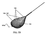
図5Aは、(被覆又は中空管の形をとる)層135がワイヤ130を連続的に包み込み又は覆う、スネアループ101aの実施形態を表す。代替的実施形態では、図5Bでスネアループ101bとして示されるように、層135が複数のセグメントに分割されて、ワイヤ130の複数の部分130’は露出したままであり、又は被覆若しくは中空管(層135)が無いままである。この不連続な又は分割された層135は、スネアループ101が伸張又は収縮するときに変形する、より柔軟なメッシュ110を提供する。ある態様によれば、(被覆又は中空管の形をとる)層135は明色(例えば青、緑、赤であるがこれらに限定されるものではない)を持つ。層135の明色は、ループ101が体液と流体連通している間の(例えば内視鏡手技中の)、ループの境界の視認性を向上させることができる。
FIG. 5A illustrates an embodiment of a
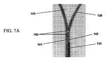
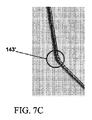
一実施形態では、本明細書のスネアループ101を製造し又は組み立てる工程中、まずワイヤ130を所望のループ形状に曲げ又は折って、その後ワイヤ130を層135で被覆し又は包み込む。ただし代替的実施形態では、まずワイヤ130を層135で被覆し又は包み込み、その後ワイヤ130を所望のループ形状に曲げ又は折る。いくつかの実施形態では、図7Aに表すように、既に所望のループ形状に曲げられ又は折られたワイヤ130は、ループ105の手元側端部に、ファスナ、ひも又は留め金140を含む。様々な実施形態において、ファスナ、ひも又は留め金140は、少なくとも1つの接合部、ハイポチューブ、少なくとも1つのクリップ又は他の任意の取付具を含み、ワイヤ130をループ105に曲げることで生じる手元側アーム141、142を結合させる。しかしながら、ワイヤ130を中空管135内に包み込む必要がある実施形態では、ファスナ、ひも又は留め金140が妨げとなる。したがって、一実施形態では、ワイヤ130を損傷させることなくまた切断領域又は切断面を滑らかに維持しながらファスナ140(例えば少なくとも1つの接合部)を切断する。図7Bに表すように、不適切に又は無造作に切断されたファスナ又はひも(例えば接合部)は、波状又はギザギザな表面143を有する一方、図7Cに表すように、適切に切断されたファスナ又はひも(例えば接合部)は、滑らかな表面143’となる。様々な実施形態において、ワイヤ130及び/又は中空管135の内部チャンネルを、乾式潤滑剤で被覆して、ワイヤ130を中空管135内に包む工程中の摩擦を減少させることができる。乾式潤滑剤の非限定的な例は、PTFE(ポリテトラフルオロエチレン)の粉末、McLube又はシリコーン油等を含む。ただしある実施形態では、接合点を設けずにワイヤ130を所望の形状に曲げ又は折る。かかる実施形態では、ワイヤ130を中空管135内に包むことが容易に成し遂げられる。
In one embodiment, during the process of manufacturing or assembling the
以下図1A、1B、2−4、5A及び5Bと図7A、7B、7C及び8−12とを同時に参照して、本明細書のある実施形態によれば、メッシュ又はネット110を被覆ループ部材105に取り付けるために、メッシュ又はネット110を被覆ループ部材105の上に配置し保持して、ワイヤ130を加熱する。メッシュ110の形状は、被覆ループ部材105の形状に近似する。またメッシュ110の寸法は、メッシュ110の一部が下方に位置する被覆ループ部材105の縁に沿った周囲を越えるように選択される。一実施形態では、メッシュ110は、被覆ループ部材105上に配置される間、意図的なたるみを有する。このたるみによって、メッシュ110を被覆ループ部材105に取り付け又は接続した後に、好ましくは被覆ループ部材105の中心155に、ポーチ145が形成される。
Referring now to FIGS. 1A, 1B, 2-4, 5A and 5B and FIGS. 7A, 7B, 7C and 8-12, according to an embodiment herein, a mesh or
図8は、メッシュ110を被覆ループ部材105に取り付けるために使用される基礎取付具175の実施形態を表す。基礎取付具175は上面177に、被覆ループ部材105の形状に近似した形状のループ保持領域176を含む。一実施形態において、ル―プ保持領域176は、被覆ループ部材105をル―プ保持領域176の上に配置した後に被覆ループ部材105を定位置に堅固に保持する、複数の磁石178を備える。ル―プ保持領域176は、基礎取付具175のル―プ保持領域176と被覆ループ部材105との間に形成される中空部を画定する。この中空部は、中にポーチ形状固定具180を受け止めるように構成される。
FIG. 8 illustrates an embodiment of a
組立のために、被覆ループ部材105はル―プ保持領域176の上に配置され、複数の磁石178は被覆ループ部材105を堅固に保持する。一実施形態では、複数の磁石178は基礎取付具175に埋め込まれ、ル―プ保持領域176が画定する周囲又は境界にほぼ沿って存在する。次に、メッシュ110は、保持された被覆ループ部材105の上に配置される。この個所で、メッシュ110の縁に沿った部分が下方の被覆ループ部材105の周囲を越えて延びるように、メッシュ110は被覆ループ部材105を覆う。その後ポーチ形状固定部180を中空部の上に位置するメッシュ110の部分上に配置することによって、メッシュ110を中空部内に位置させ、プレスし又は押し付ける。このメッシュ110のプレスによって中空部を満たし、ポーチ145(図1Bに示す)を形成する。ある態様によれば、少なくともポーチ形状固定具180の重量によって、メッシュ110を定位置に保持する。複数のガイドピン孔182によって、対応するガイドピンを導いてガイドピン孔182に挿入させ、メッシュ110、ループ105及びポーチ形状固定具180を共に位置合わせして保持し及び/又は維持することができる。
For assembly, the
メッシュ110を被覆ループ部材105に取り付け接続するために、ワイヤ130を適切な温度まで加熱して、高分子材料(ナイロン又はペバックス等)の層135を、燃焼又は分解させることなく、部分的に融解させ、柔らかくし、及び十分な粘着性又は接着性とする。この適切な温度は、少なくとも使用される具体的な高分子材料に依存する。一実施形態では、外部の電気回路/電源を用いてワイヤ130を電気的に加熱することによって、熱を層135に伝える。代替的実施形態では、その上方に位置するメッシュ110を被覆ループ部材105上で堅固に保持しながら被覆ループ部材105に熱気を送風することによって、熱を層135に伝える。様々な実施形態において、熱気の温度は120℃から180℃の範囲であり、又は結合材の融解温度の範囲内である。図9に表すように、更に他の実施形態では、焼きごて、熱プレス185(又は当業者にとって明らかな他の任意の熱源)を使用して、メッシュ110を、被覆ループ部材105の周囲の上方に位置する縁に沿って焼きごてし、熱プレスし又は熱溶接することによって熱を層135に伝える。その結果、メッシュ110の複数の高分子ストランド(例えばナイロン又はPETストランド)を粘着又は接着層135によってループのワイヤに接着し、ひいては冷却時に強固な接着を形成する。
To attach and connect the
メッシュ110を層135に(ひいては被覆ループ部材105に)強固に接着するときに、図10に表すように、被覆ループ部材105の周囲を越えて延在するメッシュ110の部分186を切断し又は切り取って、緩んだ端部又は部分186(「延在部分」とも呼ぶ)を除去する。一実施形態では、図10に表すように、レーザビーム187を使用して、延在部分186を切断し又は切り取る。代替的実施形態では、図11に表すように、メッシュ切断ダイ190を使用する。図示するように、取り付けられた、接着された又は溶融したメッシュ110及び被覆ループ部材105のアセンブリ(以下「接着アセンブリ」とも呼ぶ)は、案内又は位置合わせピン192及び194の間に配置され位置合わせされる。切断ダイ190の形状は、ループ部材105の形状に近似し、ダイ190が「接着アセンブリ」上でプレスされるときに形成されたポーチ145を囲む中空部195も有する。ダイ190を「接着アセンブリ」上で押し付け又は押圧プレスすることによって、延在部分186を切断し又は切り取る。切断ダイ190が「接着アセンブリ」上でプレスされるときに、嵌合孔192’は位置合わせピン192を受け入れて、ダイ190の「接着アセンブリ」に対する適切な位置合わせを可能とし、それによって延在部分186を正確に切断し又は切り取ることができる。更に他の実施形態では、超音波溶接を使用して延在部分186を切断し又は切り取る。超音波溶接によって熱が生成されることで、メッシュの領域を融解させて当該領域を切断する。
When the
図12に表すように、ある実施形態によれば、ループ105の手元側の丈198上に延びるメッシュ110の部分を、手元側の丈198に沿った層135の対応する部分と融着又は接着する。延在部分186(図10及び11に表す)を切断し又は切り取った後に、手元側の丈198は、手元側の丈198上に収縮管を形成するメッシュ110の融解部分を維持し、それによって、手元側の丈198及びメッシュ110の溶解部分を一緒に保持し、手元側ア―ム141、142(図7Aに見える)を十分に補強する。
As shown in FIG. 12, according to one embodiment, a portion of the
本明細書の代替的実施形態によれば、メッシュ110をワイヤ130に直接接着して、層135を不要にする。かかる実施形態では、その後乾燥させる接着剤、紫外線溶接、レーザ溶接、熱溶接、熱ステーキング又は当業者が既知の他の任意の方法を用いて、メッシュ130をワイヤ130に接着する。一実施形態では、高強度の紫外線光又は紫外線照射を用いて(接着剤を紫外線照射によって露光し又は照射することによって)、接着剤の硬化又は乾燥を加速する硬化工程において、紫外線(UV)硬化型接着剤を用いて、メッシュ110をワイヤ130に直接接着剤で付ける(層135が不要になる)。紫外線硬化型接着剤の例は、ヘンケル社が販売する接着剤のブランドであるロックタイト(登録商標)である。
According to an alternative embodiment herein, the
使用時に、軟性かつ伸縮可能な被覆ループ部材105を圧縮して有する管状部材又はシース115は、内視鏡の作業又はサービスチャンネルを通じて挿入され、目標物(体管腔内のポリープ、切り離された人体組織、異物又は詰まった食塊等)付近に配置される。目標物を捕捉しようとしているときに、被覆ループ部材105は管状部材又はシース115から外に伸び、本工程において自動的に展開し、それによって取り付けられたメッシュ110ひいてはポーチ145に対する開口部を提供する。一実施形態では、目標物がメッシュ110に捕捉されたときに、被覆ループ部材105が部分的に格納されて目標物をメッシュ部110内に固定する。他の実施形態では、目標物がメッシュ110に捕捉されると、被覆ループ部材105をシース115に格納することなく、回収装置及び目標物が患者から取り除かれる。一実施形態では、ポーチの存在が目標物を強固に保持するのに更に役立つ。
Body in use, a tubular member or
図13は、本明細書の様々な実施形態に従い、被覆ループ部材を形成してメッシュ又はネットを該被覆ループ部材に取り付け、接着し又は接続する方法の例示的なステップを示すフローチャートである。ステップ1310では、ワイヤを取得する。ワイヤは直径“d”を持ち、編組んだ鋼、ステンレス鋼、ニチノール又は当業者が既知の他の任意の形状記憶合金からなる。一実施形態では、ステップ1315aにおいて、ワイヤを厚さ“t”の高分子材料(例えばニチノール又はペバックスであるがこれらに限定されるものではない)の層で被覆し又は包み込む。ワイヤを高分子材料で被覆すること又はワイヤを高分子材料の中空管に挿入することによって、層を形成することができる。ステップ1320aでは、高分子材料の層で被覆され又は包まれたワイヤをその後、所望の形状又は寸法のループに(例えば曲げ又は折ることで)操作して、被覆ループ部材を形成する。他の実施形態では、ステップ1315bにおいて、ワイヤをまず(例えば曲げ又は折ることで)操作して所望の形状及び寸法のループにする。その後ステップ1320bにおいて、成形されたループのワイヤを高分子材料の層で被覆し又は包み込み、被覆ループ部材を形成する。
FIG. 13 is a flowchart illustrating exemplary steps of a method of forming a coated loop member and attaching, bonding, or connecting a mesh or net to the coated loop member according to various embodiments herein. In
いくつかの実施形態では、ステップ1315bにおいてまず曲げられ又は折られて所望のループ形状にされたワイヤは、ループの手元側端部にファスナ、ひも又は留め金を含み、ワイヤを曲げることによって生じた手元側のアームを一緒に保持する。様々な実施形態において、ファスナ、ひも又は留め金は、少なくとも1つの接合具、ハイポチューブ、少なくとも1つのクリップ又は当業者にとって明らかな他の任意の取付具を備える。かかる実施形態では、ワイヤを高分子材料の層(一実施形態では中空管)で被覆し又は包み込んで被覆ループ部材を形成するステップ1320bの前に、ファスナ(少なくとも1つの接合具等)がまず切断され又は除去される。 In some embodiments, the wire that is first bent or folded into the desired loop shape in step 1315b includes a fastener, lace or clasp at the proximal end of the loop, and is formed by bending the wire. Hold the arms close together. In various embodiments, the fastener, lace or clasp comprises at least one connector, hypotube, at least one clip, or any other attachment apparent to one of ordinary skill in the art. In such an embodiment, prior to step 1320b of coating or wrapping the wire with a layer of polymeric material (in one embodiment, a hollow tube) to form a coated loop member, a fastener (such as at least one connector) is first applied. Cut or removed.
様々な実施形態において、ループの所望の形状は楕円形状、円形状、ティアドロップ形状、正方形状、長方形状、四角形状又は多角形状である。一実施形態では、ループは、被覆ループ部材の中心を通る長手方向軸線に沿った第1の大きさと、長手方向軸線と垂直であり同様に被覆ループ部材の中心を通る他の軸線に沿った第2の大きさとを有する。様々な実施形態において、第1の大きさは第2の大きさよりも大きい。ある実施形態では、第1の大きさは第2の大きさと等しい。更に他の実施形態では、第1の大きさは第2の大きさよりも小さい。ステップ1315a及び続くステップ1320aを用いて、又はステップ1315b及び続くステップ1320bを用いて、被覆ループ部材が形成されることを理解されるはずである。
In various embodiments, the desired shape of the loop is elliptical, circular, teardrop, square, rectangular, square, or polygonal. In one embodiment, the loop has a first dimension along a longitudinal axis passing through the center of the covering loop member and a second dimension along another axis perpendicular to the longitudinal axis and also passing through the center of the covering loop member. 2 size. In various embodiments, the first magnitude is greater than the second magnitude. In some embodiments, the first magnitude is equal to the second magnitude. In still other embodiments, the first magnitude is smaller than the second magnitude. It should be understood that the coated loop member is formed using
次にステップ1325では、高分子材料(例えばナイロン、ポリエチレンテレフタレ-トであるがこれらに限定されるものではない)のメッシュ、ウェブ又はネットを取得する。メッシュの形状は被覆ループ部材の形状に近似し、メッシュの寸法は被覆ループ部材の寸法よりも多少大きい。ステップ1330では、被覆ループ部材を複数の磁石を有する基礎取付具の上に配置して、被覆ループ部材を定位置に保持する。その後、被覆ループ部材の縁に沿ったメッシュの一部が被覆ループ部材の周囲を越えるように、メッシュ又はネットを被覆ループ部材の上に配置又は保持する。ある実施形態では、メッシュは部分的に被覆ループ部材の周囲を覆う。他の実施形態では、メッシュは完全に被覆ループ部材の周囲を覆う。一実施形態では、ポーチ形状固定部を用いて、被覆ループ部材の中心を覆うメッシュの部分がプレスされ又は押し付けられて、基礎取付具に画定された中空部に配置され、その結果少なくともポーチ形状固定部の重量によってメッシュが定位置に保持される。これにより、メッシュが被覆ループ部材の上に配置される間に、メッシュに意図的なたるみを持たせる。このたるみによって、メッシュが被覆ループ部材に接続された後に、被覆ループ部材の中心にポーチが形成されている。
Next, in
次にステップ1335において、熱を高分子材料の層に伝える。一実施形態では、被覆ループ部材のワイヤを適切な温度まで加熱し、当該温度は高分子材料の層を、燃焼又は分解させることなく、部分的に融解させ、柔らかくし、及び十分な粘着性とし、わずかに接着性とし又は部分的に湿らせる温度である。例えば、外部の電気回路又は電源を使用して電気的に下方のワイヤを加熱する方法、被覆ループ部材を熱風にさらす方法(熱風を被覆ループ部材及びメッシュの両方に吹き付けながら、ループ上に配置したメッシュを定位置に堅固に保持する)、焼きごてを当てる方法、メッシュの上からメッシュの境界に沿って上方に存在する被覆ループ部材の周囲を熱プレスする方法、又は当業者が有利であるとわかる他の任意の方法(ただしこれらに限定されるものではない)を用いて、熱を高分子材料の層に伝える。その結果、ステップ1340では、被覆ループ部材の周囲の表面上に位置するメッシュの複数のストランドが、粘着層若しくは接着層と融着し又は粘着層若しくは接着層と接着剤で接着し、冷却時に被覆ループ部材と強固に接着する。最後に、ステップ1345では、被覆ループ部材の周囲を越えて延びる、接着したメッシュの部分を、レーザビーム、超音波溶接又はメッシュ切断ダイを用いて、切断し又は切り取る。被覆ループ部材を越えて延びる緩んだ端部又はストランドによって、内視鏡手技で使用するときにメッシュが周囲の組織を傷つけ及び/又は損傷するおそれがあるが、上記の方法によってこのような緩んだ端部又はストランドを確実に無くす。
Next, in
上記の例は、本明細書の方法及びシステムの多数の応用の単なる例示である。本発明の少数の実施形態のみを本明細書で説明したが、本発明の精神又は範囲から離れることなく、本発明を多数の他の特定の形態で具体化できることを理解できるはずである。したがって、これらの例及び実施形態を例示であると考え限定的であるとは考えず、本発明を添付の特許請求の範囲の範囲内で変更することができる。 The above examples are merely illustrative of many applications of the methods and systems herein. While only a few embodiments of the invention have been described herein, it should be understood that the invention can be embodied in many other specific forms without departing from the spirit or scope of the invention. Accordingly, these examples and embodiments are not to be considered as limiting, but rather as illustrative, and the invention may be varied within the scope of the appended claims.
Claims (20)
前記中央の開口部を囲むループ部材、及び
前記ループ部材の上に重なる材料の層を含む、
スネアループと、
前記スネアループの前記中央の開口部を横切って延在するメッシュであって、
複数の開口部、及び
複数のストランドを含み、
前記複数のストランドの第1部分は前記複数の開口部を囲み、
前記複数のストランドの第2部分は前記材料の層に結合され、前記複数のストランドの前記第2部分は前記メッシュの外縁に沿って配置され、
前記複数のストランドの前記第2部分は前記材料の層に固定されるとともに、前記材料の層に対して不動である、
メッシュと、
内腔、
手元側端部、
先端側端部、及び
先端側開口部を含み、
前記内腔は前記手元側端部及び前記先端側端部の間で延在し、前記内腔は前記先端側開口部と連通する、
シースと、
前記シースの前記内腔を通して前記中央の開口部の近位の前記スネアループの部分まで延在する運動伝達リンクであって、前記シースの前記内腔内における前記運動伝達リンクの移動は、
前記スネアループの少なくとも一部及び前記メッシュの少なくとも一部を、前記シースの前記先端側開口部から遠位に移動させるとともに、
前記スネアループの少なくとも一部及び前記メッシュの少なくとも一部を、前記シースの前記先端側開口部内に近位に移動させ、ここで前記スネアループ及び前記メッシュが前記シースの前記先端側開口部を通して移動する間、前記複数のストランドの前記第2部分は前記材料の層に対して静止状態を維持するように構成される、
運動伝達リンクと、
前記中央の開口部の近位の前記スネアループの前記部分の上の収縮被覆であって、前記収縮被覆の手元側端部は前記運動伝達リンクの前記先端側端部よりも遠位に位置する、収縮被覆と、からなる、回収装置。 Central opening,
A loop member surrounding the central opening, and a layer of material overlying the loop member;
A snare loop,
A mesh extending across the central opening of the snare loop;
Including a plurality of openings, and a plurality of strands,
A first portion of the plurality of strands surrounds the plurality of openings;
A second portion of the plurality of strands is bonded to the layer of material; the second portion of the plurality of strands is disposed along an outer edge of the mesh;
The second portion of the plurality of strands is fixed to the layer of the material and is immovable with respect to the layer of the material;
Mesh and
lumen,
Hand side end,
Including the distal end, and the distal opening,
The lumen extends between the proximal end and the distal end, and the lumen communicates with the distal opening.
A sheath,
A motion transmission link extending through the lumen of the sheath to a portion of the snare loop proximal to the central opening, wherein movement of the motion transmission link within the lumen of the sheath comprises:
At least a portion of the snare loop and at least a portion of the mesh are moved distally from the distal opening of the sheath,
At least a portion of the snare loop and at least a portion of the mesh are moved proximally into the distal opening of the sheath, wherein the snare loop and the mesh move through the distal opening of the sheath. While the second portion of the plurality of strands is configured to remain stationary with respect to the layer of material.
A motion transmission link ,
A shrink wrap over the portion of the snare loop proximal to the central opening, wherein a proximal end of the shrink wrap is located more distally than the distal end of the motion transmission link. And a shrink coating.
第1手元側アーム及び第2手元側アームを含むループ部材、
前記スネアループを通る中央の開口部、及び
前記中央の開口部を画定する前記ループ部材の少なくとも一部の上に重なる材料の層を含む、
スネアループと、
前記スネアループの前記中央の開口部を横切って延在するネットであって、
複数のストランド、及び
前記複数のストランドの第1部分の間の複数の開口部を含み、
前記複数のストランドの第2部分は前記材料の層に結合され、前記複数のストランドの前記第2部分は1つ以上の終端を含み、前記1つ以上の終端は直接的かつ不動的に前記材料の層に固定される、
ネットと、
内腔、
手元側端部、
先端側端部、及び
先端側開口部を含み、
前記内腔は前記手元側端部及び前記先端側端部の間で延在し、前記内腔は前記先端側開口部と連通する、
シースと、
前記シースの前記内腔を通して前記スネアループまで延在する運動伝達リンクであって、前記シースの前記内腔内における前記運動伝達リンクの移動は、前記スネアループ及び前記ネットを前記シースに対して移動させるように構成され、前記材料の層に結合された前記複数のストランドの前記第2部分は、前記シースの前記先端側開口部の内外への、前記スネアループ及び前記ネットの移動の間、前記材料の層に対して位置的に固定された状態を維持する、
運動伝達リンクと、
前記第1手元側アームを前記第2手元側アームに固定するように構成された収縮被膜であって、前記第1手元側アーム及び前記第2手元側アームは前記収縮被膜内において互いに接触し、前記収縮被膜は前記ネットの一部を含む、
収縮被覆と、からなる、
回収装置。 A snare loop,
A loop member including a first proximal arm and a second proximal arm,
A central opening through the snare loop; and a layer of material overlying at least a portion of the loop member defining the central opening.
A snare loop,
A net extending across the central opening of the snare loop,
A plurality of strands, and a plurality of openings between first portions of the plurality of strands,
A second portion of the plurality of strands is bonded to a layer of the material, the second portion of the plurality of strands includes one or more terminations, and the one or more terminations are directly and immovably coupled to the material. Fixed to the layers of
Net and
lumen,
Hand side end,
Including the distal end, and the distal opening,
The lumen extends between the proximal end and the distal end, and the lumen communicates with the distal opening.
A sheath,
A motion transmission link extending through the lumen of the sheath to the snare loop, wherein movement of the motion transmission link within the lumen of the sheath moves the snare loop and the net relative to the sheath. Wherein the second portion of the plurality of strands coupled to the layer of material is moved into and out of the distal opening of the sheath during movement of the snare loop and the net. Maintaining a positionally fixed state with respect to the layer of material,
A motion transmission link ,
A shrinkable coating configured to secure the first proximal arm to the second proximal arm, wherein the first proximal arm and the second proximal arm contact each other within the shrinkable coating; Wherein the shrink coating comprises a portion of the net;
And shrink coating.
Collection device.
前記ループ部材に囲まれた中央の開口部、及び
前記ループ部材の上の材料の層であって、前記材料の層は前記ループ部材の第1側の第1セクション、及び前記第1側と反対の前記ループ部材の第2側の第2セクションを含む、材料の層を含む、
スネアループと、
前記スネアループの前記中央の開口部を横切って延在するメッシュであって、
複数のストランド、及び
前記複数のストランドの第1部分に接する複数の開口部であって、前記複数のストランドの第2部分は、前記ループ部材の上の前記材料の層の前記第2セクションに結合されることなく、前記ループ部材の上の前記材料の層の前記第1セクションに結合される、複数の開口部を含む、
メッシュと、
内腔、
手元側端部、
先端側端部、及び
先端側開口部を含み、
前記内腔は前記手元側端部及び前記先端側端部の間で延在し、前記内腔は前記先端側開口部と連通し、前記スネアループ及び前記メッシュは前記先端側開口部から延在可能であるとともに、前記先端側開口部内に格納可能である、
シースと、
前記シースの前記内腔を通して前記中央の開口部の近位の前記スネアループの部分まで延在する運動伝達リンクであって、前記シースの前記内腔内における前記運動伝達リンクの移動は、
前記スネアループの少なくとも一部及び前記メッシュの少なくとも一部を、前記シースの前記先端側開口部から遠位に移動させるとともに、
前記スネアループの少なくとも一部及び前記メッシュの少なくとも一部を、前記シースの前記先端側開口部内に近位に移動させ、ここで前記スネアループ及び前記メッシュが前記シースの前記先端側開口部を通して移動する間、前記複数のストランドの前記第2部分は前記材料の層に対して静止状態を維持するように構成される、
運動伝達リンクと、
前記第1手元側アームを前記第2手元側アームに固定するように構成された固定層であって、前記第1手元側アーム及び前記第2手元側アームは前記固定層によって一緒にまとめられ、前記固定層は前記メッシュの手元側端部に位置する、
固定層と、からなる、
回収装置。 A loop member including a first proximal arm and a second proximal arm,
Opening of the center surrounded by the loop member, and a layer of material over the said loop member, opposite said layer of material first side first section of the loop member, and the first side A layer of material comprising a second section on a second side of the loop member of
A snare loop ,
A mesh extending across the central opening of the snare loop ;
A plurality of strands, and a plurality of openings in contact with a first portion of the plurality of strands, wherein a second portion of the plurality of strands is coupled to the second section of the layer of material over the loop member. Including a plurality of openings coupled to the first section of the layer of material over the loop member without being performed.
Mesh and
lumen,
Hand side end,
Including the distal end, and the distal opening,
The lumen extends between the proximal end and the distal end, the lumen communicates with the distal opening, and the snare loop and the mesh extend from the distal opening. And can be stored in the distal opening.
A sheath,
A motion transmission link extending through the lumen of the sheath to a portion of the snare loop proximal to the central opening, wherein movement of the motion transmission link within the lumen of the sheath comprises:
At least a portion of the snare loop and at least a portion of the mesh are moved distally from the distal opening of the sheath,
At least a portion of the snare loop and at least a portion of the mesh are moved proximally into the distal opening of the sheath, wherein the snare loop and the mesh move through the distal opening of the sheath. While the second portion of the plurality of strands is configured to remain stationary with respect to the layer of material.
A motion transmission link ,
A fixed layer configured to fix the first hand arm to the second hand arm, wherein the first hand arm and the second hand arm are grouped together by the fixed layer; The fixing layer is located at a proximal end of the mesh,
And a fixed layer,
Collection device.
Applications Claiming Priority (5)
| Application Number | Priority Date | Filing Date | Title |
|---|---|---|---|
| US201462052538P | 2014-09-19 | 2014-09-19 | |
| US62/052,538 | 2014-09-19 | ||
| US201562162786P | 2015-05-17 | 2015-05-17 | |
| US62/162,786 | 2015-05-17 | ||
| PCT/US2015/050949 WO2016044729A1 (en) | 2014-09-19 | 2015-09-18 | Method of attaching a mesh to a coated loop member of a surgical snare device |
Related Child Applications (1)
| Application Number | Title | Priority Date | Filing Date |
|---|---|---|---|
| JP2019226331A Division JP7139306B2 (en) | 2014-09-19 | 2019-12-16 | How to attach the mesh to the loop member |
Publications (3)
| Publication Number | Publication Date |
|---|---|
| JP2017530756A JP2017530756A (en) | 2017-10-19 |
| JP2017530756A5 JP2017530756A5 (en) | 2018-11-01 |
| JP6634440B2 true JP6634440B2 (en) | 2020-01-22 |
Family
ID=55524684
Family Applications (4)
| Application Number | Title | Priority Date | Filing Date |
|---|---|---|---|
| JP2017513146A Active JP6634440B2 (en) | 2014-09-19 | 2015-09-18 | Surgical retrieval device |
| JP2019226331A Active JP7139306B2 (en) | 2014-09-19 | 2019-12-16 | How to attach the mesh to the loop member |
| JP2022142249A Active JP7386946B2 (en) | 2014-09-19 | 2022-09-07 | Collection device |
| JP2023193669A Pending JP2024020387A (en) | 2014-09-19 | 2023-11-14 | Collection device |
Family Applications After (3)
| Application Number | Title | Priority Date | Filing Date |
|---|---|---|---|
| JP2019226331A Active JP7139306B2 (en) | 2014-09-19 | 2019-12-16 | How to attach the mesh to the loop member |
| JP2022142249A Active JP7386946B2 (en) | 2014-09-19 | 2022-09-07 | Collection device |
| JP2023193669A Pending JP2024020387A (en) | 2014-09-19 | 2023-11-14 | Collection device |
Country Status (5)
| Country | Link |
|---|---|
| US (2) | US10149691B2 (en) |
| EP (1) | EP3193747A4 (en) |
| JP (4) | JP6634440B2 (en) |
| CN (3) | CN110584745B (en) |
| WO (1) | WO2016044729A1 (en) |
Cited By (1)
| Publication number | Priority date | Publication date | Assignee | Title |
|---|---|---|---|---|
| JP7386946B2 (en) | 2014-09-19 | 2023-11-27 | エンドチョイス インコーポレイテッド | Collection device |
Families Citing this family (24)
| Publication number | Priority date | Publication date | Assignee | Title |
|---|---|---|---|---|
| US8100822B2 (en) | 2004-03-16 | 2012-01-24 | Macroplata Systems, Llc | Anoscope for treating hemorrhoids without the trauma of cutting or the use of an endoscope |
| US9565998B2 (en) | 2009-12-16 | 2017-02-14 | Boston Scientific Scimed, Inc. | Multi-lumen-catheter retractor system for a minimally-invasive, operative gastrointestinal treatment |
| US10966701B2 (en) | 2009-12-16 | 2021-04-06 | Boston Scientific Scimed, Inc. | Tissue retractor for minimally invasive surgery |
| US10758116B2 (en) | 2009-12-16 | 2020-09-01 | Boston Scientific Scimed, Inc. | System for a minimally-invasive, operative gastrointestinal treatment |
| US10595711B2 (en) | 2009-12-16 | 2020-03-24 | Boston Scientific Scimed, Inc. | System for a minimally-invasive, operative gastrointestinal treatment |
| US8932211B2 (en) | 2012-06-22 | 2015-01-13 | Macroplata, Inc. | Floating, multi-lumen-catheter retractor system for a minimally-invasive, operative gastrointestinal treatment |
| EP2512577B1 (en) | 2009-12-16 | 2018-03-07 | Boston Scientific Scimed, Inc. | Arrangements for effecting an endoluminal anatomical structure |
| US10531869B2 (en) | 2009-12-16 | 2020-01-14 | Boston Scientific Scimed, Inc. | Tissue retractor for minimally invasive surgery |
| USRE48850E1 (en) | 2009-12-16 | 2021-12-14 | Boston Scientific Scimed, Inc. | Multi-lumen-catheter retractor system for a minimally-invasive, operative gastrointestinal treatment |
| US9186131B2 (en) | 2009-12-16 | 2015-11-17 | Macroplata, Inc. | Multi-lumen-catheter retractor system for a minimally-invasive, operative gastrointestinal treatment |
| US9572591B2 (en) | 2013-09-03 | 2017-02-21 | United States Endoscopy Group, Inc. | Endoscopic snare device |
| US10881384B2 (en) | 2014-09-19 | 2021-01-05 | Endochoice, Inc. | Method of attaching a mesh to a coated loop member of a surgical snare device |
| CN116373331A (en) * | 2015-10-23 | 2023-07-04 | 安多卓思公司 | Method of attaching a mesh to a coated loop member of a surgical snare device |
| US11141177B2 (en) | 2015-11-30 | 2021-10-12 | Piranha Medical Llc | Blockage clearing devices, systems, and methods |
| US10722267B2 (en) | 2015-11-30 | 2020-07-28 | Piranha Medical, LLC | Blockage removal |
| DE102016106955A1 (en) * | 2016-04-14 | 2017-10-19 | medwork GmbH | Fremdkörperbergeeinrichtung for an endoscopic device, and endoscopic device |
| JP2018047030A (en) * | 2016-09-21 | 2018-03-29 | 富士フイルム株式会社 | Endoscope |
| CN106510817A (en) * | 2016-11-17 | 2017-03-22 | 南京微创医学科技股份有限公司 | Medical foreign matter recoverer |
| DE102016226295A1 (en) | 2016-12-29 | 2018-07-05 | Epflex Feinwerktechnik Gmbh | Medical catch nets instrument |
| CN110087526B (en) | 2016-12-30 | 2022-01-14 | 波士顿科学国际有限公司 | System for minimally invasive treatment inside body cavity |
| EP3565487B1 (en) | 2017-01-09 | 2024-03-06 | United States Endoscopy Group, Inc. | Retrieval device |
| US11116529B2 (en) * | 2017-02-24 | 2021-09-14 | Stryker Corporation | Embolectomy device having multiple semi-tubular clot engaging structures |
| CN116327271A (en) | 2017-03-18 | 2023-06-27 | 波士顿科学国际有限公司 | System for minimally invasive treatment within a body cavity |
| US11832789B2 (en) | 2019-12-13 | 2023-12-05 | Boston Scientific Scimed, Inc. | Devices, systems, and methods for minimally invasive surgery in a body lumen |
Family Cites Families (25)
| Publication number | Priority date | Publication date | Assignee | Title |
|---|---|---|---|---|
| US3124136A (en) | 1964-03-10 | Method of repairing body tissue | ||
| US5759187A (en) | 1991-11-05 | 1998-06-02 | Wilk & Nakao Medical Technology, Incorporated | Surgical retrieval assembly and associated method |
| US5486182A (en) * | 1991-11-05 | 1996-01-23 | Wilk & Nakao Medical Technology Inc. | Polyp retrieval assembly with separable web member |
| US5741271A (en) * | 1991-11-05 | 1998-04-21 | Nakao; Naomi L. | Surgical retrieval assembly and associated method |
| US5782840A (en) * | 1997-02-14 | 1998-07-21 | Wilk & Nakao Medical Technology, Inc. | Snare cauterization surgical instrument assembly and method of manufacture |
| WO1999053851A1 (en) | 1998-04-17 | 1999-10-28 | Wilk And Nakao Medical Technology, Incorporated | Surgical retrieval assembly and associated method |
| US20030060842A1 (en) | 2001-09-27 | 2003-03-27 | Yem Chin | Method and apparatus for measuring and controlling blade depth of a tissue cutting apparatus in an endoscopic catheter |
| US7163550B2 (en) * | 2003-03-26 | 2007-01-16 | Scimed Life Systems, Inc. | Method for manufacturing medical devices from linear elastic materials while maintaining linear elastic properties |
| US20040267306A1 (en) * | 2003-04-11 | 2004-12-30 | Velocimed, L.L.C. | Closure devices, related delivery methods, and related methods of use |
| JP2008539807A (en) * | 2003-10-14 | 2008-11-20 | キューブ メディカル エーエス | Medical supplies |
| US8048103B2 (en) * | 2003-11-06 | 2011-11-01 | Boston Scientific Scimed, Inc. | Flattened tip filter wire design |
| US9399121B2 (en) | 2004-04-21 | 2016-07-26 | Acclarent, Inc. | Systems and methods for transnasal dilation of passageways in the ear, nose or throat |
| US8932208B2 (en) | 2005-05-26 | 2015-01-13 | Maquet Cardiovascular Llc | Apparatus and methods for performing minimally-invasive surgical procedures |
| US7618437B2 (en) * | 2005-07-15 | 2009-11-17 | Granit Medical Innovation, Llc | Endoscope retrieval instrument assembly |
| US8591521B2 (en) * | 2007-06-08 | 2013-11-26 | United States Endoscopy Group, Inc. | Retrieval device |
| EP3679874B1 (en) * | 2007-06-08 | 2024-04-10 | United States Endoscopy Group, Inc. | Retrieval device |
| US8435237B2 (en) | 2008-01-29 | 2013-05-07 | Covidien Lp | Polyp encapsulation system and method |
| US20090240238A1 (en) * | 2008-03-24 | 2009-09-24 | Medtronic Vascular, Inc. | Clot Retrieval Mechanism |
| EP2493392B1 (en) * | 2009-10-30 | 2016-04-13 | Cook Medical Technologies LLC | Apparatus for maintaining a force upon tissue using a loop member |
| WO2012054762A2 (en) * | 2010-10-20 | 2012-04-26 | Medtronic Ardian Luxembourg S.A.R.L. | Catheter apparatuses having expandable mesh structures for renal neuromodulation and associated systems and methods |
| US20130023894A1 (en) * | 2011-07-22 | 2013-01-24 | Rafic Saleh | Surgical retrieval apparatus and method with semi-rigidly extendable and collapsable basket |
| US9439661B2 (en) | 2013-01-09 | 2016-09-13 | Covidien Lp | Connection of a manipulation member, including a bend without substantial surface cracks, to an endovascular intervention device |
| US9936964B2 (en) * | 2014-05-15 | 2018-04-10 | Boston Scientific Scimed, Inc. | Retrieval devices and related methods of use |
| CN110584745B (en) | 2014-09-19 | 2023-07-11 | 恩多巧爱思股份有限公司 | Method of attaching a mesh to a coated ring member of a surgical snare device |
| CN204364096U (en) | 2014-11-25 | 2015-06-03 | 安瑞医疗器械(杭州)有限公司 | Foreign matter removal device |
-
2015
- 2015-09-18 CN CN201910875934.2A patent/CN110584745B/en active Active
- 2015-09-18 WO PCT/US2015/050949 patent/WO2016044729A1/en active Application Filing
- 2015-09-18 EP EP15842562.9A patent/EP3193747A4/en active Pending
- 2015-09-18 CN CN202310711219.1A patent/CN116672004A/en active Pending
- 2015-09-18 JP JP2017513146A patent/JP6634440B2/en active Active
- 2015-09-18 CN CN201580050688.7A patent/CN106714709B/en active Active
- 2015-09-18 US US14/858,622 patent/US10149691B2/en active Active
-
2018
- 2018-10-30 US US16/175,601 patent/US11083474B2/en active Active
-
2019
- 2019-12-16 JP JP2019226331A patent/JP7139306B2/en active Active
-
2022
- 2022-09-07 JP JP2022142249A patent/JP7386946B2/en active Active
-
2023
- 2023-11-14 JP JP2023193669A patent/JP2024020387A/en active Pending
Cited By (1)
| Publication number | Priority date | Publication date | Assignee | Title |
|---|---|---|---|---|
| JP7386946B2 (en) | 2014-09-19 | 2023-11-27 | エンドチョイス インコーポレイテッド | Collection device |
Also Published As
| Publication number | Publication date |
|---|---|
| US11083474B2 (en) | 2021-08-10 |
| JP2024020387A (en) | 2024-02-14 |
| JP7139306B2 (en) | 2022-09-20 |
| JP7386946B2 (en) | 2023-11-27 |
| CN110584745B (en) | 2023-07-11 |
| CN116672004A (en) | 2023-09-01 |
| CN110584745A (en) | 2019-12-20 |
| JP2017530756A (en) | 2017-10-19 |
| JP2022177089A (en) | 2022-11-30 |
| EP3193747A1 (en) | 2017-07-26 |
| US10149691B2 (en) | 2018-12-11 |
| US20160081702A1 (en) | 2016-03-24 |
| JP2020049250A (en) | 2020-04-02 |
| WO2016044729A1 (en) | 2016-03-24 |
| EP3193747A4 (en) | 2018-05-30 |
| US20190059919A1 (en) | 2019-02-28 |
| CN106714709B (en) | 2019-10-15 |
| CN106714709A (en) | 2017-05-24 |
Similar Documents
| Publication | Publication Date | Title |
|---|---|---|
| JP6634440B2 (en) | Surgical retrieval device | |
| JP7218291B2 (en) | Recovery device | |
| CA2282239C (en) | Improved snare cauterization surgical instrument assembly and method of manufacture | |
| EP2651462B1 (en) | Expandable implant and implant system | |
| JP2020513938A (en) | System for delivering a catheter | |
| JP7459348B2 (en) | How to attach mesh to loop member | |
| US20210137509A1 (en) | Method of attaching a mesh to a coated loop member of a surgical snare device | |
| US20150119895A1 (en) | Multifunction retrieval devices and related methods | |
| US20240032930A1 (en) | Cinch ligating assembly |
Legal Events
| Date | Code | Title | Description |
|---|---|---|---|
| RD03 | Notification of appointment of power of attorney |
Free format text: JAPANESE INTERMEDIATE CODE: A7423 Effective date: 20170815 |
|
| RD04 | Notification of resignation of power of attorney |
Free format text: JAPANESE INTERMEDIATE CODE: A7424 Effective date: 20170905 |
|
| A521 | Request for written amendment filed |
Free format text: JAPANESE INTERMEDIATE CODE: A523 Effective date: 20180914 |
|
| A621 | Written request for application examination |
Free format text: JAPANESE INTERMEDIATE CODE: A621 Effective date: 20180914 |
|
| A977 | Report on retrieval |
Free format text: JAPANESE INTERMEDIATE CODE: A971007 Effective date: 20190712 |
|
| A131 | Notification of reasons for refusal |
Free format text: JAPANESE INTERMEDIATE CODE: A131 Effective date: 20190813 |
|
| A521 | Request for written amendment filed |
Free format text: JAPANESE INTERMEDIATE CODE: A523 Effective date: 20191101 |
|
| TRDD | Decision of grant or rejection written | ||
| A01 | Written decision to grant a patent or to grant a registration (utility model) |
Free format text: JAPANESE INTERMEDIATE CODE: A01 Effective date: 20191119 |
|
| A61 | First payment of annual fees (during grant procedure) |
Free format text: JAPANESE INTERMEDIATE CODE: A61 Effective date: 20191216 |
|
| R150 | Certificate of patent or registration of utility model |
Ref document number: 6634440 Country of ref document: JP Free format text: JAPANESE INTERMEDIATE CODE: R150 |
|
| R250 | Receipt of annual fees |
Free format text: JAPANESE INTERMEDIATE CODE: R250 |
|
| R250 | Receipt of annual fees |
Free format text: JAPANESE INTERMEDIATE CODE: R250 |