JP6604246B2 - Information processing apparatus, information processing system, information processing method, and program - Google Patents
Information processing apparatus, information processing system, information processing method, and program Download PDFInfo
- Publication number
- JP6604246B2 JP6604246B2 JP2016055805A JP2016055805A JP6604246B2 JP 6604246 B2 JP6604246 B2 JP 6604246B2 JP 2016055805 A JP2016055805 A JP 2016055805A JP 2016055805 A JP2016055805 A JP 2016055805A JP 6604246 B2 JP6604246 B2 JP 6604246B2
- Authority
- JP
- Japan
- Prior art keywords
- information processing
- unit
- procedure
- output
- visit
- Prior art date
- Legal status (The legal status is an assumption and is not a legal conclusion. Google has not performed a legal analysis and makes no representation as to the accuracy of the status listed.)
- Active
Links
Images


Classifications
-
- H—ELECTRICITY
- H04—ELECTRIC COMMUNICATION TECHNIQUE
- H04N—PICTORIAL COMMUNICATION, e.g. TELEVISION
- H04N1/00—Scanning, transmission or reproduction of documents or the like, e.g. facsimile transmission; Details thereof
- H04N1/23—Reproducing arrangements
- H04N1/2307—Circuits or arrangements for the control thereof, e.g. using a programmed control device, according to a measured quantity
- H04N1/2338—Circuits or arrangements for the control thereof, e.g. using a programmed control device, according to a measured quantity according to user specified instructions, e.g. user selection of reproduction mode
-
- G—PHYSICS
- G06—COMPUTING; CALCULATING OR COUNTING
- G06F—ELECTRIC DIGITAL DATA PROCESSING
- G06F16/00—Information retrieval; Database structures therefor; File system structures therefor
- G06F16/90—Details of database functions independent of the retrieved data types
- G06F16/903—Querying
-
- G—PHYSICS
- G06—COMPUTING; CALCULATING OR COUNTING
- G06F—ELECTRIC DIGITAL DATA PROCESSING
- G06F3/00—Input arrangements for transferring data to be processed into a form capable of being handled by the computer; Output arrangements for transferring data from processing unit to output unit, e.g. interface arrangements
- G06F3/12—Digital output to print unit, e.g. line printer, chain printer
- G06F3/1201—Dedicated interfaces to print systems
- G06F3/1202—Dedicated interfaces to print systems specifically adapted to achieve a particular effect
- G06F3/1203—Improving or facilitating administration, e.g. print management
- G06F3/1204—Improving or facilitating administration, e.g. print management resulting in reduced user or operator actions, e.g. presetting, automatic actions, using hardware token storing data
-
- G—PHYSICS
- G06—COMPUTING; CALCULATING OR COUNTING
- G06F—ELECTRIC DIGITAL DATA PROCESSING
- G06F3/00—Input arrangements for transferring data to be processed into a form capable of being handled by the computer; Output arrangements for transferring data from processing unit to output unit, e.g. interface arrangements
- G06F3/12—Digital output to print unit, e.g. line printer, chain printer
- G06F3/1201—Dedicated interfaces to print systems
- G06F3/1223—Dedicated interfaces to print systems specifically adapted to use a particular technique
- G06F3/1237—Print job management
- G06F3/1238—Secure printing, e.g. user identification, user rights for device usage, unallowed content, blanking portions or fields of a page, releasing held jobs
-
- G—PHYSICS
- G06—COMPUTING; CALCULATING OR COUNTING
- G06F—ELECTRIC DIGITAL DATA PROCESSING
- G06F3/00—Input arrangements for transferring data to be processed into a form capable of being handled by the computer; Output arrangements for transferring data from processing unit to output unit, e.g. interface arrangements
- G06F3/12—Digital output to print unit, e.g. line printer, chain printer
- G06F3/1201—Dedicated interfaces to print systems
- G06F3/1223—Dedicated interfaces to print systems specifically adapted to use a particular technique
- G06F3/1237—Print job management
- G06F3/126—Job scheduling, e.g. queuing, determine appropriate device
-
- G—PHYSICS
- G06—COMPUTING; CALCULATING OR COUNTING
- G06F—ELECTRIC DIGITAL DATA PROCESSING
- G06F3/00—Input arrangements for transferring data to be processed into a form capable of being handled by the computer; Output arrangements for transferring data from processing unit to output unit, e.g. interface arrangements
- G06F3/12—Digital output to print unit, e.g. line printer, chain printer
- G06F3/1201—Dedicated interfaces to print systems
- G06F3/1223—Dedicated interfaces to print systems specifically adapted to use a particular technique
- G06F3/1237—Print job management
- G06F3/1267—Job repository, e.g. non-scheduled jobs, delay printing
-
- G—PHYSICS
- G06—COMPUTING; CALCULATING OR COUNTING
- G06F—ELECTRIC DIGITAL DATA PROCESSING
- G06F3/00—Input arrangements for transferring data to be processed into a form capable of being handled by the computer; Output arrangements for transferring data from processing unit to output unit, e.g. interface arrangements
- G06F3/12—Digital output to print unit, e.g. line printer, chain printer
- G06F3/1201—Dedicated interfaces to print systems
- G06F3/1278—Dedicated interfaces to print systems specifically adapted to adopt a particular infrastructure
- G06F3/1292—Mobile client, e.g. wireless printing
-
- H—ELECTRICITY
- H04—ELECTRIC COMMUNICATION TECHNIQUE
- H04N—PICTORIAL COMMUNICATION, e.g. TELEVISION
- H04N1/00—Scanning, transmission or reproduction of documents or the like, e.g. facsimile transmission; Details thereof
- H04N1/00127—Connection or combination of a still picture apparatus with another apparatus, e.g. for storage, processing or transmission of still picture signals or of information associated with a still picture
- H04N1/00204—Connection or combination of a still picture apparatus with another apparatus, e.g. for storage, processing or transmission of still picture signals or of information associated with a still picture with a digital computer or a digital computer system, e.g. an internet server
- H04N1/00236—Connection or combination of a still picture apparatus with another apparatus, e.g. for storage, processing or transmission of still picture signals or of information associated with a still picture with a digital computer or a digital computer system, e.g. an internet server using an image reading or reproducing device, e.g. a facsimile reader or printer, as a local input to or local output from a computer
-
- H—ELECTRICITY
- H04—ELECTRIC COMMUNICATION TECHNIQUE
- H04N—PICTORIAL COMMUNICATION, e.g. TELEVISION
- H04N1/00—Scanning, transmission or reproduction of documents or the like, e.g. facsimile transmission; Details thereof
- H04N1/00127—Connection or combination of a still picture apparatus with another apparatus, e.g. for storage, processing or transmission of still picture signals or of information associated with a still picture
- H04N1/00281—Connection or combination of a still picture apparatus with another apparatus, e.g. for storage, processing or transmission of still picture signals or of information associated with a still picture with a telecommunication apparatus, e.g. a switched network of teleprinters for the distribution of text-based information, a selective call terminal
- H04N1/00307—Connection or combination of a still picture apparatus with another apparatus, e.g. for storage, processing or transmission of still picture signals or of information associated with a still picture with a telecommunication apparatus, e.g. a switched network of teleprinters for the distribution of text-based information, a selective call terminal with a mobile telephone apparatus
-
- H—ELECTRICITY
- H04—ELECTRIC COMMUNICATION TECHNIQUE
- H04N—PICTORIAL COMMUNICATION, e.g. TELEVISION
- H04N1/00—Scanning, transmission or reproduction of documents or the like, e.g. facsimile transmission; Details thereof
- H04N1/00127—Connection or combination of a still picture apparatus with another apparatus, e.g. for storage, processing or transmission of still picture signals or of information associated with a still picture
- H04N1/00344—Connection or combination of a still picture apparatus with another apparatus, e.g. for storage, processing or transmission of still picture signals or of information associated with a still picture with a management, maintenance, service or repair apparatus
-
- H—ELECTRICITY
- H04—ELECTRIC COMMUNICATION TECHNIQUE
- H04N—PICTORIAL COMMUNICATION, e.g. TELEVISION
- H04N1/00—Scanning, transmission or reproduction of documents or the like, e.g. facsimile transmission; Details thereof
- H04N1/32—Circuits or arrangements for control or supervision between transmitter and receiver or between image input and image output device, e.g. between a still-image camera and its memory or between a still-image camera and a printer device
- H04N1/327—Initiating, continuing or ending a single-mode communication; Handshaking therefor
- H04N1/32765—Initiating a communication
- H04N1/32771—Initiating a communication in response to a request, e.g. for a particular document
- H04N1/32776—Initiating a communication in response to a request, e.g. for a particular document using an interactive, user-operated device, e.g. a computer terminal, mobile telephone
-
- H—ELECTRICITY
- H04—ELECTRIC COMMUNICATION TECHNIQUE
- H04N—PICTORIAL COMMUNICATION, e.g. TELEVISION
- H04N2201/00—Indexing scheme relating to scanning, transmission or reproduction of documents or the like, and to details thereof
- H04N2201/0008—Connection or combination of a still picture apparatus with another apparatus
- H04N2201/0034—Details of the connection, e.g. connector, interface
- H04N2201/0037—Topological details of the connection
- H04N2201/0039—Connection via a network
-
- H—ELECTRICITY
- H04—ELECTRIC COMMUNICATION TECHNIQUE
- H04N—PICTORIAL COMMUNICATION, e.g. TELEVISION
- H04N2201/00—Indexing scheme relating to scanning, transmission or reproduction of documents or the like, and to details thereof
- H04N2201/0008—Connection or combination of a still picture apparatus with another apparatus
- H04N2201/0034—Details of the connection, e.g. connector, interface
- H04N2201/0048—Type of connection
- H04N2201/0055—By radio
-
- H—ELECTRICITY
- H04—ELECTRIC COMMUNICATION TECHNIQUE
- H04N—PICTORIAL COMMUNICATION, e.g. TELEVISION
- H04N2201/00—Indexing scheme relating to scanning, transmission or reproduction of documents or the like, and to details thereof
- H04N2201/0077—Types of the still picture apparatus
- H04N2201/0094—Multifunctional device, i.e. a device capable of all of reading, reproducing, copying, facsimile transception, file transception
-
- H—ELECTRICITY
- H04—ELECTRIC COMMUNICATION TECHNIQUE
- H04N—PICTORIAL COMMUNICATION, e.g. TELEVISION
- H04N2201/00—Indexing scheme relating to scanning, transmission or reproduction of documents or the like, and to details thereof
- H04N2201/32—Circuits or arrangements for control or supervision between transmitter and receiver or between image input and image output device, e.g. between a still-image camera and its memory or between a still-image camera and a printer device
- H04N2201/3201—Display, printing, storage or transmission of additional information, e.g. ID code, date and time or title
- H04N2201/3204—Display, printing, storage or transmission of additional information, e.g. ID code, date and time or title of data relating to a user, sender, addressee, machine or electronic recording medium
- H04N2201/3205—Display, printing, storage or transmission of additional information, e.g. ID code, date and time or title of data relating to a user, sender, addressee, machine or electronic recording medium of identification information, e.g. name or ID code
Landscapes
- Engineering & Computer Science (AREA)
- Theoretical Computer Science (AREA)
- General Engineering & Computer Science (AREA)
- Human Computer Interaction (AREA)
- Physics & Mathematics (AREA)
- General Physics & Mathematics (AREA)
- Multimedia (AREA)
- Signal Processing (AREA)
- Databases & Information Systems (AREA)
- Computing Systems (AREA)
- Computer Networks & Wireless Communication (AREA)
- Computational Linguistics (AREA)
- Data Mining & Analysis (AREA)
- Facsimiles In General (AREA)
- Accessory Devices And Overall Control Thereof (AREA)
- Information Transfer Between Computers (AREA)
- Management, Administration, Business Operations System, And Electronic Commerce (AREA)
Description
本発明は、情報処理装置、情報処理システム、情報処理方法、及びプログラムに関する。 The present invention relates to an information processing apparatus, an information processing system, an information processing method, and a program.
コンピュータシステムが業務等において一般的に利用されるようになり、業務等に関する文書は、紙文書又は電子文書のいずれかの形態で扱われている。 Computer systems are generally used in business and the like, and documents relating to business and the like are handled in either form of paper documents or electronic documents.
このような状況において、例えば、ワークフロー等における或る局面にて入力又は出力が可能な文書の形態は紙文書及び電子文書のいずれか一方である場合が多い。 In such a situation, for example, the form of a document that can be input or output in a certain aspect of a workflow or the like is often either a paper document or an electronic document.
しかしながら、紙文書又は電子文書のいずれの形態の文書が扱い易いかについては、ユーザごとに異なることが考えられる。また、周囲に画像形成装置が設置されているか否か等の状況に応じて、紙文書で扱いたいか、又は電子文書で扱いたいかが異なることも考えられる。 However, it may be different for each user as to whether a paper document or an electronic document is easy to handle. Also, depending on the situation such as whether or not an image forming apparatus is installed in the surrounding area, it may be different depending on whether the document is handled as a paper document or an electronic document.
本発明は、上記の点に鑑みてなされたものであって、文書の入力又は出力に関する制限を緩和することを目的とする。 The present invention has been made in view of the above points, and it is an object of the present invention to relax restrictions on input or output of a document.
そこで上記課題を解決するため、情報処理装置は、当該情報処理装置のユーザを特定する特定部と、特定されたユーザに関してネットワークを介して当該情報処理装置に接続される記憶部に記憶されている、データの出力先を示す情報を取得する第1の取得部と、無線通信を介して機器を探索する探索部と、前記探索部によって機器が発見された場合に、当該機器に対して前記データの出力の実行を要求する要求部と、前記探索部によって機器が発見されなかった場合に、前記データの出力を当該情報処理装置に実行させる実行部と、を有し、前記実行部は、前記情報が当該情報処理装置を示す場合は、前記探索部による探索結果に関わらず、前記データの出力を当該情報処理装置に実行させる。 Therefore, in order to solve the above problem, the information processing apparatus is stored in a specifying unit that specifies a user of the information processing apparatus and a storage unit that is connected to the information processing apparatus via the network regarding the specified user. a first acquisition unit that acquires information indicating an output destination of the data, a search unit for searching for a device via a wireless communication, when the device is found by the search unit, the data relative to the apparatus a request unit for requesting execution of the output of, when said device is not found by the search unit, the output of the data have a, an execution unit to be executed by the information processing apparatus, the execution unit When the information indicates the information processing apparatus, the information processing apparatus is caused to output the data regardless of a search result by the search unit .
文書の入力又は出力に関する制限を緩和することができる。 Restrictions on document input or output can be relaxed.
以下、図面に基づいて本発明の実施の形態を説明する。図1は、本発明の実施の形態における情報処理システムの構成例を示す図である。図1において、情報処理システム1は、サーバ装置30、画像形成装置10、ユーザ端末20、及び管理者端末40等を含む。画像形成装置10及び管理者端末40は、LAN(Local Area Network)又はインターネット等のネットワークを介してサーバ装置30と通信可能である。ユーザ端末20は、画像形成装置10及びサーバ装置30と無線通信によって通信可能である。
Hereinafter, embodiments of the present invention will be described with reference to the drawings. FIG. 1 is a diagram illustrating a configuration example of an information processing system according to an embodiment of the present invention. In FIG. 1, the
サーバ装置30は、情報処理システム1によって実現されるワークフローにおいて利用される各種の情報を管理する。
The
画像形成装置10は、例えば、複合機である。画像形成装置10は、ワークフローにおいて操作対象とされる文書の入力元又は出力先として利用される。
The
ユーザ端末20は、例えば、スマートフォン又はタブレット端末等のスマート端末である。但し、表示装置を備え、無線通信が可能な他の端末がユーザ端末20として利用されてもよい。ユーザ端末20は、ワークフローにおいて操作対象とされる文書の入力元又は出力先として利用される。以下における「ユーザ」とは、特に断りが無い限り、ユーザ端末20のユーザをいう。
The
管理者端末40は、ワークフローが適用された業務の管理者等が利用するPC(Personal Computer)等の端末である。
The
本実施の形態では、図2に示されるような訪問票に関するワークフロー(以下、「訪問票フロー」という。)を、ワークフローの一例として説明する。 In the present embodiment, a workflow related to a visit form as shown in FIG. 2 (hereinafter referred to as “visit form flow”) will be described as an example of the workflow.
図2は、訪問票フローを説明するための図である。例えば、介護訪問であれば、管理者が、予め介護訪問者の訪問先等を決定し、斯かる訪問を依頼する文書である訪問依頼票を作成する(S1)。作成された訪問依頼票は、サーバ装置30に記憶される。サーバ装置30は、訪問依頼票の作成に応じて訪問票を生成すると共に(S2)、訪問依頼の発生を、訪問者(図2では、A社員)のユーザ端末20に通知する(S3)。なお、訪問票とは、指定された訪問先を訪問した訪問者が、訪問先で得られた情報を記入する文書をいう。例えば、介護訪問であれば、介護訪問者が訪問先で状況調査を行った結果を記入する文書が、訪問票である。訪問者は、訪問依頼通知に応じ、ユーザ端末20又は画像形成装置10を利用して訪問票を受け取る(S4)。なお、本実施の形態では、ユーザ端末20を利用して電子文書の状態で訪問票を受け取ることもできるし、画像形成装置10を利用して紙文書の状態で訪問票を受け取ることもできる。
FIG. 2 is a diagram for explaining the visit form flow. For example, in the case of a care visit, the administrator determines a visit destination of the care visitor in advance, and creates a visit request form that is a document for requesting such a visit (S1). The created visit request form is stored in the
なお、販売訪問等、介護訪問以外の訪問に関して訪問票フローが適用されてもよい。または、他の文書に関するワークフローに関して本実施の形態が適用されてもよい。 It should be noted that the visit form flow may be applied to visits other than nursing care visits such as sales visits. Alternatively, the present embodiment may be applied to a workflow related to another document.
図3は、本発明の実施の形態における画像形成装置のハードウェア構成例を示す図である。図3において、画像形成装置10は、コントローラ11、スキャナ12、プリンタ13、モデム14、操作パネル15、ネットワークインタフェース16、及びSDカードスロット17等のハードウェアを有する。
FIG. 3 is a diagram illustrating a hardware configuration example of the image forming apparatus according to the embodiment of the present invention. 3, the
コントローラ11は、CPU111、RAM112、ROM113、HDD114、及びNVRAM115等を有する。ROM113には、各種のプログラムやプログラムによって利用されるデータ等が記憶されている。RAM112は、プログラムをロードするための記憶領域や、ロードされたプログラムのワーク領域等として用いられる。CPU111は、RAM112にロードされたプログラムを処理することにより、各種の機能を実現する。HDD114には、プログラムやプログラムが利用する各種のデータ等が記憶される。NVRAM115には、各種の設定情報等が記憶される。
The
スキャナ12は、原稿より画像データを読み取るためのハードウェア(画像読取手段)である。プリンタ13は、印刷データを印刷用紙に印刷するためのハードウェア(印刷手段)である。モデム14は、電話回線に接続するためのハードウェアであり、FAX通信による画像データの送受信を実行するために用いられる。操作パネル15は、ユーザからの入力の受け付けを行うためのボタン等の入力手段や、液晶パネル等の表示手段等を備えたハードウェアである。液晶パネルは、タッチパネル機能を有していてもよい。この場合、当該液晶パネルは、入力手段の機能をも兼ねる。ネットワークインタフェース16は、LAN等のネットワーク(有線又は無線の別は問わない。)に接続するためのハードウェアである。SDカードスロット17は、SDカード80に記憶されたプログラムを読み取るために利用される。すなわち、画像形成装置10では、ROM113に記憶されたプログラムだけでなく、SDカード80に記憶されたプログラムもRAM112にロードされ、実行されうる。なお、他の記録媒体(例えば、CD−ROM又はUSB(Universal Serial Bus)メモリ等)によってSDカード80が代替されてもよい。すなわち、SDカード80の位置付けに相当する記録媒体の種類は、所定のものに限定されない。この場合、SDカードスロット17は、記録媒体の種類に応じたハードウェアによって代替されればよい。
The
図4は、本発明の実施の形態におけるユーザ端末のハードウェア構成例を示す図である。図4において、ユーザ端末20は、CPU201、メモリ202、補助記憶装置203、タッチパネル204、及び無線通信装置205等を有する。
FIG. 4 is a diagram illustrating a hardware configuration example of the user terminal according to the embodiment of the present invention. 4, the
補助記憶装置203は、ユーザ端末20にインストールされたプログラム等を記憶する。メモリ202は、プログラムの起動指示があった場合に、補助記憶装置203からプログラムを読み出して記憶する。CPU201は、メモリ202に記憶されたプログラムに従ってユーザ端末20に係る機能を実現する。
The
タッチパネル204は、入力機能と表示機能との双方を備えた電子部品であり、情報の表示や、ユーザからの入力の受け付け等を行う。タッチパネル204は、表示装置211及び入力装置212等を含む。
The
表示装置211は、液晶ディスプレイ等であり、タッチパネル204の表示機能を担う。入力装置212は、表示装置211に対する接触物の接触を検出するセンサを含む電子部品である。接触物の接触の検出方式は、静電方式、抵抗膜方式、又は光学方式等、公知の方式のいずれであってもよい。なお、接触物とは、タッチパネル204の接触面(表面)に接触する物体をいう。斯かる物体の一例として、ユーザの指や専用又は一般のペン等が挙げられる。
The
無線通信装置205は、無線信を行うために必要とされるアンテナ等の電子部品である。
The
図5は、本発明の実施の形態におけるサーバ装置の機能構成例を示す図である。図5において、サーバ装置30は、認証処理部31、ドキュメント管理部32、訪問票サービス部33、及び機器情報配信部34等を有する。これら各部は、サーバ装置30にインストールされた1以上のプログラムが、サーバ装置30のCPUに実行させる処理により実現される。サーバ装置30は、また、ユーザ情報記憶部35、ドキュメント記憶部36、ドキュメント情報記憶部37、訪問票フロー情報記憶部38、及び機器情報記憶部39等を有する。これら各記憶部は、例えば、サーバ装置30の補助記憶装置、又はサーバ装置30にネットワークを介して接続可能な記憶装置等を用いて実現可能である。
FIG. 5 is a diagram illustrating a functional configuration example of the server device according to the embodiment of the present invention. 5, the
認証処理部31は、ユーザ端末20のユーザ又は画像形成装置10のユーザについて、ユーザ情報記憶部35を参照して認証処理を実行する。認証処理によって、ユーザ端末20のユーザ又は画像形成装置10のユーザが特定される。ユーザ情報記憶部35には、ユーザごとに、ユーザID、パスワード、名前等の属性情報や、訪問票フローに関する設定情報等が記憶されている。
The
ドキュメント管理部32は、訪問票フローにおいて処理対象とされる文書である訪問票を管理する。訪問票の管理には、ドキュメント記憶部36及びドキュメント情報記憶部37が利用される。ドキュメント記憶部36には、訪問票の実体(例えば、PDF(Portable Document Format)データ)が記憶される。ドキュメント情報記憶部37には、各訪問票について、ユーザによる操作履歴が記憶される。具体的には、ドキュメント情報記憶部37には、各訪問票について、生成、出力(表示又は印刷)、出力の完了、又は更新等が行われるごとに、レコードが記憶される。
The
訪問票サービス部33は、訪問票フローに特化した処理を実行するサーバ側のアプリケーションプログラムである。例えば、訪問票サービス部33は、訪問依頼票を受信すると、訪問票を生成する。訪問票フロー情報記憶部38には、訪問票フロー管理するために必要な情報が記憶される。
The visit
機器情報配信部34は、機器情報記憶部39に記憶されている情報をユーザ端末20に配信する。機器情報記憶部39には、画像形成装置10ごとに、対応可能な操作方式や、印刷性能に関する情報等が記憶されている。操作方式については後述される。
The device
図6は、本発明の実施の形態におけるユーザ端末の機能構成例を示す図である。図6において、ユーザ端末20は、訪問票アプリ21及びアプリ連携部22等を有する。これら各部は、ユーザ端末20にインストールされた1以上のプログラムが、CPU201に実行させる処理により実現される。
FIG. 6 is a diagram illustrating a functional configuration example of the user terminal according to the embodiment of the present invention. In FIG. 6, the
訪問票アプリ21は、訪問票フローに関する処理を実行するクライアント側のアプリケーションプログラムである。
The
アプリ連携部22は、サーバ装置30における訪問票サービス部33と、訪問票アプリ21とを連携させるための処理を実行する。アプリ連携部22は、また、文書(訪問票)の入出力に関して抽象化されたインタフェースを訪問票アプリ21に提供する。抽象化されたインタフェースとは、例えば、入力形態又は出力形態について、訪問票アプリ21が関与しないインタフェースをいう。例えば、アプリ連携部22は、「出力」の要求を受けると、ユーザに適した形態で文書の出力(例えば、表示又は印刷等)を行う。また、アプリ連携部22は、訪問票フローに関するユーザの認証等を行う。アプリ連携部22は、本実施の形態では、訪問票アプリ21と連携して処理を実行するが、特定のアプリケーションプログラムに依存しない。
The
図6において、アプリ連携部22は、ユーザ通知部221、認証要求部222、アプリ管理部223、周辺機器調査部224、及びドキュメント入出力部225等を含む。アプリ連携部22は、また、アプリ連携情報記憶部231、周辺機器情報記憶部232、及びドキュメント情報記憶部233等を利用する。これら各記憶部は、例えば、補助記憶装置203又はメモリ202等を用いて実現可能である。
In FIG. 6, the
ユーザ通知部221は、ワークフローの開始をユーザに通知する。本実施の形態では、ユーザ通知部221は、訪問依頼をユーザに通知する。
The
認証要求部222は、ユーザから認証情報(ユーザID及びパスワード)の入力を受け付け、当該認証情報に基づくユーザの認証をサーバ装置30へ要求することで、ユーザ端末20のユーザを特定する。
The
アプリ管理部223は、ユーザの認証に成功した場合にサーバ装置30から送信されるアプリ連携情報に指定されているアプリケーションプログラム(訪問票アプリ21)を起動する。なお、アプリ連携情報には、操作対象の訪問票の識別情報(以下、「ドキュメントID」という。)等が含まれる。受信されたアプリ連携情報は、アプリ連携情報記憶部231に記憶される。ドキュメントID等は、ドキュメント情報記憶部233に記憶される。
The
周辺機器調査部224は、ユーザ端末20の周辺又は近辺に所在する入出力機器(本実施の形態では画像形成装置10)を探索する。周辺機器調査部224は、発見された(検出された)画像形成装置10に関する情報を、周辺機器情報記憶部232に記憶する。
The peripheral
ドキュメント入出力部225は、アプリ管理部223によって起動された訪問票アプリ21から、文書(訪問票)の入力又は出力の要求を受け付ける。
The document input /
図7は、本発明の実施の形態における画像形成装置の機能構成例を示す図である。図7において、画像形成装置10は、訪問票アプリ121及びアプリ連携部130等を有する。これら各部は、画像形成装置10にインストールされた1以上のプログラムが、CPU111に実行させる処理により実現される。
FIG. 7 is a diagram illustrating a functional configuration example of the image forming apparatus according to the embodiment of the present invention. In FIG. 7, the
訪問票アプリ121及びアプリ連携部130の機能は、基本的にユーザ端末20における訪問票アプリ21及びアプリ連携部22と同様である。すなわち、ユーザ通知部131、認証要求部132、アプリ管理部133、周辺機器調査部134、ドキュメント入出力部135、アプリ連携情報記憶部141、周辺機器情報記憶部142、ドキュメント情報記憶部143は、それぞれ、ユーザ通知部221、認証要求部222、アプリ管理部223、周辺機器調査部224、ドキュメント入出力部225、アプリ連携情報記憶部231、周辺機器情報記憶部232、ドキュメント情報記憶部233に対応する
但し、アプリ連携部130は、端末連携部136を有している点において、アプリ連携部22と異なる。端末連携部136は、ユーザ端末20と画像形成装置10との無線通信を介した連携を可能にするための処理を実行する。
The functions of the
なお、アプリ連携情報記憶部141、周辺機器情報記憶部142、及びドキュメント情報記憶部143は、例えば、HDD114、RAM112、又は画像形成装置10にネットワークを介して接続可能な記憶装置等を用いて実現可能である。
The application cooperation
続いて、訪問票フローに関する出力方式について説明する。本実施の形態では、以下のケース1〜ケース3の3つの出力方式が提供される。3つの中から採用される出力方式は、ユーザやユーザの周辺の状況等に依存して決定される。
Next, an output method related to the visit form flow will be described. In the present embodiment, the following three output methods of
図8は、ケース1の手順の概要を説明するための図である。管理者によって入力された訪問依頼が管理者端末40からサーバ装置30へ送信されると、サーバ装置30は訪問票を生成する(S1)。サーバ装置30は、訪問依頼において訪問者として指定されたユーザのユーザ端末20に対し、訪問依頼通知を送信する(S2)。ユーザ端末20は、訪問依頼通知に対応する訪問票をサーバ装置30から取得して編集可能な状態で表示する(S3)。その後、ユーザは、ユーザ端末20において表示された訪問票を、ユーザ端末20を用いて編集することができる。
FIG. 8 is a diagram for explaining an outline of the procedure of
すなわち、ケース1において、訪問票の出力形態は、ユーザ端末20による表示である。したがって、この場合、ユーザは、画像形成装置10を利用する必要はない。ケース1は、訪問票を電子文書の状態で扱いたいユーザに適した出力方式である。
That is, in
図9は、ケース2の手順の概要を説明するための図である。管理者端末40からの訪問依頼に応じてサーバ装置30が訪問票を生成し、訪問依頼通知がユーザ端末20に送信されるまで(S1、S2)は、ケース1と同じである。訪問依頼通知を確認したユーザは、画像形成装置10の設置場所に移動する(S3)。画像形成装置10は、ユーザによる操作に応じ、当該訪問依頼通知に対応する訪問票をサーバ装置30から取得して、印刷する(S4)。
FIG. 9 is a diagram for explaining the outline of the procedure of
すなわち、ケース2において、訪問票の出力形態は、画像形成装置10による印刷である。ケース2は、訪問票を紙文書の状態で扱いたいユーザに適した出力方式である。
That is, in
図10は、ケース3の手順の概要を説明するための図である。管理者端末40からの訪問依頼に応じてサーバ装置30が訪問票を生成し、訪問依頼通知がユーザ端末20に送信されると、ユーザが画像形成装置10の設置場所に移動するまで(S1〜S3)は、ケース2と同じである。
FIG. 10 is a diagram for explaining the outline of the procedure of
ケース3では、画像形成装置10への移動後においても、ユーザは、ユーザ端末20を操作する。ユーザによる指示は、ユーザ端末20と画像形成装置10との間による無線通信によって、画像形成装置10に伝達される。画像形成装置10は、このように伝達されるユーザの指示に応じ、当該訪問依頼通知に対応する訪問票をサーバ装置30から取得して、印刷する(S4)。
In
すなわち、ケース3において、訪問票の出力形態は、画像形成装置10による印刷である。ケース3は、訪問票を紙文書の状態で扱いたいユーザであって、ユーザ端末20を利用して画像形成装置10を操作したいユーザに適した出力方式である。
That is, in
以下においては、ケース1、ケース2、ケース3を、第1の実施の形態、第2の実施の形態、第3の実施の形態に順番で説明する。
In the following, the
図11は、第1の実施の形態における訪問依頼処理の処理手順の一例を説明するための図である。 FIG. 11 is a diagram for explaining an example of a processing procedure of a visit request process according to the first embodiment.
ステップS101において、管理者端末40は、管理者からのログイン操作を受け付ける。ログイン操作において、管理者のユーザID及びパスワードが入力される。管理者端末40は、当該ユーザID及びパスワードを含む、管理者としてのログイン要求をサーバ装置30へ送信する(S101)。
In step S101, the
サーバ装置30の認証処理部31は、ログイン要求を受信すると、当該ログイン要求に含まれているユーザID及びパスワードについて、ユーザ情報記憶部35を参照して認証処理を実行する(S102)。
When receiving the login request, the
図12は、ユーザ情報記憶部の構成例を示す図である。図12に示されるように、ユーザ情報記憶部35には、ユーザID、パスワード、名前、端末ID、入出力形態、優先操作、フローID、及びアプリID等を含むユーザ情報がユーザごとに記憶されている。
FIG. 12 is a diagram illustrating a configuration example of the user information storage unit. As shown in FIG. 12, the user
ユーザIDは、ユーザごとの識別情報である。名前は、ユーザの名前である。端末IDは、ユーザが利用するユーザ端末20の識別情報である。端末IDは、サーバ装置30がユーザ端末20と通信する際に、ユーザ端末20を識別可能な情報であればよい。入出力形態は、文書(訪問票)の入出力の形態である。本実施の形態では、入出力形態として、電子文書を意味する「電子」又は紙文書を意味する「紙」が設定可能である。優先操作は、文書の操作の際に優先的に選択される操作方法を示す情報である。「端末」は、ユーザ端末20による操作を意味し、ケース1に対応する。「オペパネ」は、画像形成装置10の操作パネル15を介した操作を意味し、ケース2に対応する。「リモート」は、ユーザ端末20による画像形成装置10のリモート操作を意味し、ケース3に対応する。フローIDは、ユーザに対応付くワークフローの識別情報である。「S01」は、訪問票フローのフローIDである。アプリIDは、ワークフローにおいてクライアント側(ユーザ端末20又は画像形成装置10)において起動されるべきアプリケーションプログラムの識別情報である。「url.s01」は、訪問票アプリ21及び訪問票121のアプリIDを示す。なお、アプリIDは、例えば、URL(Uniform Resource Locator)であってもよい。
The user ID is identification information for each user. The name is the name of the user. The terminal ID is identification information of the
ステップS102では、ログイン要求に含まれるユーザID及びパスワードが、「管理者」を名前とするユーザ情報のユーザID及びパスワードに一致すれば、認証処理は成功する。認証処理に失敗した場合、ステップS103以降は実行されない。 In step S102, if the user ID and password included in the login request match the user ID and password of the user information whose name is “administrator”, the authentication process is successful. If the authentication process fails, step S103 and subsequent steps are not executed.
続いて、管理者は、認証の成功に応じて管理者端末40に表示されるアップロード画面を操作して、訪問依頼票のアップロード指示を入力する。管理者端末40は、当該指示に応じ、訪問依頼票をサーバ装置30へ送信する(S103)。
Subsequently, the administrator operates an upload screen displayed on the
図13は、訪問依頼票の構成例を示す図である。図13に示されるように、訪問依頼票は、訪問依頼ごとに、訪問者名、訪問先氏名、訪問先住所、及び訪問指定日等の各項目の値を含む。訪問者名は、訪問者の名前である。訪問先氏名は、訪問先(被訪問者)の氏名である。訪問先住所は、訪問先の住所である。訪問指定日は、訪問者が訪問先を訪問すべき日である。 FIG. 13 is a diagram illustrating a configuration example of a visit request slip. As shown in FIG. 13, the visit request slip includes values of items such as a visitor name, a visit name, a visit address, and a visit designated date for each visit request. The visitor name is the name of the visitor. The visited name is the name of the visited (visited person). The visited address is the address of the visited address. The designated visit date is the date on which the visitor should visit the visited site.
図13に示されるように、1度に複数の訪問依頼が入力されてもよい。なお、図13では、訪問依頼票が表形式の構造を有する例が示されているが、訪問依頼票は、CSV(Comma Separated Values)形式やXML(eXtensible Markup Language)形式等、他のデータ形式を有してもよい。 As shown in FIG. 13, a plurality of visit requests may be input at a time. FIG. 13 shows an example in which the visit request form has a tabular structure. However, the visit request form has other data formats such as a CSV (Comma Separated Values) format and an XML (eXtensible Markup Language) format. You may have.
サーバ装置30の訪問票サービス部33は、訪問依頼票を受信すると、当該訪問依頼票に含まれている訪問依頼ごとに、訪問票の電子データ(以下、単に「訪問票」という。)を生成する(S104)。
Upon receiving the visit request form, the visit
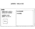
図14は、訪問票の一例を示す図である。図14に示されるように、訪問票は、訪問依頼の内容や、訪問結果(状況調査結果)を記入する領域や、訪問相手によってサインを記入してもらう領域等を含む。 FIG. 14 is a diagram illustrating an example of a visit form. As shown in FIG. 14, the visit form includes an area for entering the contents of the visit request, a visit result (situation survey result), an area for receiving a signature by the visitor, and the like.
訪問票サービス部33は、生成した訪問票を、ドキュメント管理部32に入力する。ドキュメント管理部32は、当該訪問票をドキュメント記憶部36に記憶すると共に、訪問票が生成されたことを示す履歴を、ドキュメント情報記憶部37に記憶する。
The visit
図15は、ドキュメント情報記憶部の構成例を示す図である。図15において、ドキュメント情報記憶部37のレコードは、ユーザID、ドキュメントID、ステータス、出力先、日付、及びフローID等の項目ごとに値を含む。
FIG. 15 is a diagram illustrating a configuration example of the document information storage unit. In FIG. 15, the record in the document
ユーザIDは、訪問票に係る訪問者のユーザIDである。当該ユーザIDは、訪問依頼に含まれている訪問者名を名前として含むユーザ情報に基づいて特定可能である。ドキュメントIDは、訪問票の識別情報である。例えば、訪問票がファイル形式でドキュメント記憶部36に記憶される場合、ファイル名がドキュメントIDとして利用されてもよい。ステータスは、訪問票の状態である。このタイミングで生成されるレコードには、「未閲覧」が記憶される。出力先は、訪問票が出力された際に、その出力先の識別情報が記憶される項目である。日付は、レコードが生成された日付である。フローIDは、ドキュメントIDに対応する文書(訪問票)を処理対象とするワークフローのフローIDである。本実施の形態では、訪問票フローのフローIDが記憶される。
The user ID is a user ID of a visitor related to the visit slip. The user ID can be specified based on user information including the visitor name included in the visit request as a name. The document ID is identification information of the visit form. For example, when the visit form is stored in the
なお、図15には、一つの訪問票(ID01.pdf)に関して、閲覧が行われ、編集(更新)が行われた状態に対応するレコードも記憶された状態が示されているが、このタイミングでは、1行目のレコードのみが記憶される。また、図13に示したように、訪問依頼票に複数の訪問依頼が含まれている場合には、各訪問票に関して、1行目と同様のレコードがドキュメント情報記憶部37に記憶される。
FIG. 15 shows a state in which a record corresponding to a state in which browsing and editing (update) are performed is stored for one visit form (ID01.pdf). Then, only the record in the first line is stored. As shown in FIG. 13, when a plurality of visit requests are included in the visit request form, a record similar to the first line is stored in the document
訪問票サービス部33は、また、各訪問票に係る訪問票フローを管理するための情報(以下、「訪問票フロー情報」という。)を、訪問票フロー情報記憶部38に記憶する。
The visit
図16は、訪問票フロー情報記憶部の構成例を示す図である。図16に示されるように、訪問票フロー情報記憶部38には、生成された訪問票ごとに、ユーザID、名前、訪問先氏名、訪問先住所、訪問指定日、ジョブID、及びドキュメントID等が記憶される。
FIG. 16 is a diagram illustrating a configuration example of the visit form flow information storage unit. As shown in FIG. 16, the visit form flow
ユーザID及びドキュメントIDには、訪問票に関してドキュメント情報記憶部37に記憶されたユーザID及びドキュメントIDが転記される。名前、訪問先氏名、訪問先住所、訪問指定日には、訪問依頼に含まれていた値が転記される。ジョブIDは、訪問票フローのジョブの識別情報である。訪問票ごとの訪問票フローのジョブとは、各訪問票に関して実行される訪問票フローの実行単位をいう。ジョブIDは、訪問票サービス部33によって生成される。なお、本実施の形態において、ジョブIDは、ドキュメントIDから拡張子を除去した値である。
In the user ID and the document ID, the user ID and the document ID stored in the document
続いて、訪問票サービス部33は、訪問依頼ごとに、当該訪問依頼における訪問者に対応するユーザ端末20に対して訪問依頼通知を送信する(S105)。訪問依頼における訪問者に対応するユーザ端末20は、当該訪問依頼に含まれている訪問者名を含むユーザ情報(図12)に含まれている端末IDに基づいて特定可能である。なお、訪問依頼通知には、例えば、当該訪問依頼に係る訪問票に関してドキュメント情報記憶部37に記憶されたフローIDが含まれる。
Subsequently, for each visit request, the visit
ユーザ端末20のユーザ通知部221は、訪問依頼通知を受信すると、訪問依頼通知画面を表示装置211に表示して、訪問依頼の発生をユーザに通知する(S106)。
Upon receiving the visit request notification, the
図17は、第1の実施の形態における画面遷移の一例を示す図である。図17には、第1の実施の形態において表示される各画面について、表示順、表示場所、及び表示主体等が判別可能なように示されている。すなわち、各画面は左から右方向の順に表示される。また、ユーザ端末20の矩形に包含されている画面は、ユーザ端末20において表示される。アプリ連携部22に対応する破線によって囲まれている画面は、アプリ連携部22によって表示される。訪問票アプリ21に対応する破線によって囲まれている画面は、訪問票アプリ21によって表示される。
FIG. 17 is a diagram illustrating an example of screen transition in the first embodiment. FIG. 17 shows each screen displayed in the first embodiment so that the display order, the display location, the display subject, and the like can be distinguished. That is, each screen is displayed in order from left to right. The screen included in the rectangle of the
ステップS106では、左端の訪問依頼通知画面510が表示装置211に表示される。訪問依頼通知画面510は、ログイン指示を受け付けるためのリンク511を含む。
In step S <b> 106, the leftmost visit
続いて、訪問依頼通知に応じて訪問票が出力されるまでの処理手順について説明する。図18は、第1の実施の形態における訪問票の出力処理の処理手順の一例を説明するための図である。図18中、図11と同一ステップ(S105及びS106)には、同一ステップ番号を付し、その説明は省略する。なお、ここでは、A社員に対する訪問依頼について説明する。「A社員」とは、或るユーザの名前である。 Next, a processing procedure until a visit slip is output in response to a visit request notification will be described. FIG. 18 is a diagram for explaining an example of a processing procedure of a visit form output process according to the first embodiment. In FIG. 18, the same steps (S105 and S106) as those in FIG. 11 are denoted by the same step numbers, and the description thereof is omitted. Here, a visit request for the employee A will be described. “Employee A” is the name of a certain user.
A社員は、訪問依頼通知画面510を参照することにより、訪問依頼通知の発生を確認する(S111)。続いて、A社員が、訪問依頼通知画面510のリンク511を指示(例えば、タッチ等)すると、認証要求部222は、ログイン画面520を表示する(S112)。ログイン画面520は、図17に示されるように、ユーザIDとパスワードとの入力を受け付けるための領域を有する。
The A employee confirms the occurrence of the visit request notification by referring to the visit request notification screen 510 (S111). Subsequently, when the employee A instructs (for example, touch) the
A社員が、ユーザID及びパスワードをログイン画面520に入力すると(S113)、認証要求部222は、入力されたユーザID及びパスワードと、認証依頼通知に含まれていた訪問票フローのフローIDとを含む認証要求を、サーバ装置30へ送信する(S114)。サーバ装置30の認証処理部31は、当該認証要求に含まれているユーザID及びパスワードについて、ユーザ情報記憶部35(図12)を参照して認証処理を実行する(S115)。認証に成功した場合、ステップS116以降が実行されない。
When the employee A inputs the user ID and password to the login screen 520 (S113), the
認証に成功すると、認証要求に含まれていたフローIDに対応する訪問票サービス部33は、認証要求の送信元のユーザ端末20へアプリ連携情報を送信する(S116)。アプリ連携情報には、認証されたユーザのユーザ情報と、当該ユーザに対する訪問票フローのジョブIDとが含まれる。ユーザ端末20のアプリ管理部223は、当該アプリ連携情報を受信すると、当該アプリ連携情報をアプリ連携情報記憶部231に記憶する(S117)。
If the authentication is successful, the visit
図19は、アプリ連携情報記憶部の構成例を示す図である。図19に示されるように、アプリ連携情報記憶部231には、アプリ連携情報が記憶される。アプリ連携情報は、ユーザ情報(図12)とジョブIDとを含む。なお、図19には、A社員のユーザ情報と、A社員に対する訪問票フロー情報(図16)に含まれているジョブIDとが示されている。
FIG. 19 is a diagram illustrating a configuration example of the application cooperation information storage unit. As shown in FIG. 19, the application cooperation
続いて、アプリ管理部223は、アプリ連携情報に基づく出力方式の判定処理を実行する(S118)。出力方式の判定処理では、A社員に適した出力方式がケース1〜ケース3のいずれに該当するかが判定される。当該判定処理の詳細については後述する。また、アプリ管理部223は、判定結果に応じた態様で、アプリ連携情報に含まれているアプリIDに対応するアプリケーション(すなわち、訪問票アプリ21)の起動を要求する。ここでは、ケース1を示すパラメータが、訪問票アプリ21の起動オプションに付与される。また、アプリ連携情報も訪問票アプリ21に通知される。
Subsequently, the
訪問票アプリ21は、起動されると、訪問票アプリ21の操作画面530を表示装置211に表示する(S119)。図17に示されるように、操作画面530は、訪問票閲覧ボタン531を含む。すなわち、ここではケース1に対応して訪問票の表示指示(閲覧指示)を受け付けるために、訪問票アプリ21は、訪問票閲覧ボタン531を操作画面530内に配置する。
When started, the
続いて、A社員が、訪問票閲覧ボタン531を押下すると(S121)、訪問票アプリ21は、アプリ連携情報に含まれているジョブID(以下、「対象ジョブID」という。)を指定して、訪問票の出力をドキュメント入出力部225に要求する(S122)。具体的には、訪問票アプリ21は、アプリ連携部22が提供する、ドキュメントの出力要求を受け付けるためのインタフェースを呼び出すことで、ドキュメントの出力をドキュメント入出力部225に要求する。続いて、ドキュメント入出力部225は、訪問票の取得要求をサーバ装置30へ送信する(S123)。当該取得要求には、対象ジョブIDが含まれる。
Subsequently, when the employee A presses the visit form browsing button 531 (S121), the
サーバ装置30の訪問票サービス部33は、当該取得要求を受信すると、当該取得要求に含まれている対象ジョブIDに対応する訪問票を、ドキュメント管理部32を介してドキュメント記憶部36から取得する。より詳しくは、訪問票サービス部33は、対象ジョブIDに対応するドキュメントIDを訪問票フロー情報記憶部38(図16)を参照して特定し、当該ドキュメントIDと、取得要求の送信元のユーザ端末20の端末IDとをドキュメント管理部32に通知する。ドキュメント管理部32は、当該ドキュメントIDに係る訪問票をドキュメント記憶部36から取得する。この際、ドキュメント管理部32は、当該ドキュメントIDに係る訪問票に関する操作履歴をドキュメント情報記憶部37に記憶する。図15の2行目に示されるように、ステータスが「閲覧中」であるレコードがドキュメント情報記憶部37に追加される。当該レコードの出力先には、訪問票サービス部33から通知された端末IDが記憶される。訪問票サービス部33は、ドキュメント管理部32によって取得された訪問票をユーザ端末20に返信する(S131)。
Upon receipt of the acquisition request, the visit
ユーザ端末20のドキュメント入出力部225は、当該訪問票を受信すると、ドキュメント表示画面540を表示装置211に表示する(S140)。図17において、ドキュメント表示画面540は、ドキュメント表示領域541を含む。図17では簡略化されているが、ドキュメント表示領域541には、図14に示した訪問票が表示される。
Upon receiving the visit slip, the document input /
A社員は、表示された訪問票を参照することで、訪問依頼の内容を確認することができる。訪問依頼の内容を確認したA社員が、ドキュメント表示画面540のOKボタン542を押下すると(S141)、ドキュメント入出力部225は、訪問票の閲覧済み通知をサーバ装置30へ送信する(S142)。当該通知には対象ジョブIDが含まれる。
The A employee can confirm the contents of the visit request by referring to the displayed visit form. When the employee A confirming the contents of the visit request presses the
サーバ装置30の訪問票サービス部33は、当該通知を受信すると、当該通知に含まれている対象ジョブIDに対応する訪問票の閲覧の完了をドキュメント管理部32に通知する。ドキュメント管理部32は、当該訪問票の操作履歴をドキュメント情報記憶部に記憶する(S143)。例えば、図15の3行目に示されるように、ステータスが「閲覧済み」であるレコードがドキュメント情報記憶部に追加される。
When receiving the notification, the visit
続いて、ステップS118の詳細について説明する。図20は、アプリ連携情報に基づく出力方式の判定処理の処理手順の一例を説明するための図である。 Next, details of step S118 will be described. FIG. 20 is a diagram for explaining an example of the processing procedure of the output method determination process based on the application cooperation information.
ステップS201において、アプリ管理部223は、ステップS117において受信されたアプリ連携情報(図19)に含まれている入出力形態が、「電子」であるか「紙」であるかを判定する。入出力形態が「電子」である場合、アプリ管理部223は、ユーザ端末20のユーザに適した出力方式は、ケース1であると判定する(S202)。
In step S201, the
一方、入出力形態が「紙」である場合、周辺機器調査部224は、ユーザ端末20の周辺の画像形成装置10を探索し、発見された(検出された)画像形成装置10から機器情報を取得する(S203)。取得された機器情報は、周辺機器情報記憶部232に記憶される。
On the other hand, when the input / output form is “paper”, the peripheral
図21は、周辺機器情報記憶部の構成例を示す図である。図21に示されるように、周辺機器情報記憶部232には、発見された画像形成装置10ごとに、機器名称、機体番号、状態、優先利用、操作方式、及び印刷情報等が記憶される。このうち、優先利用を除く項目の値が、発見された画像形成装置10から取得される。但し、以下において、機器情報というとき、当該機器情報には、優先利用も含まれることとする。
FIG. 21 is a diagram illustrating a configuration example of the peripheral device information storage unit. As illustrated in FIG. 21, the peripheral device
機器名称は、画像形成装置10ごとにユーザによって設定される名称(例えば、ホスト名)である。機体番号は、画像形成装置10の製造時又は出荷時等に決定される画像形成装置10の個体ごとの識別情報である。状態は、画像形成装置10の印刷機能の状態であり、印刷の可否を示す。但し、過去に発見されて今回発見されなかった画像形成装置10に関する状態の値は、「非接続」である。すなわち、周辺機器情報記憶部232には、過去のいずれかのタイミングにおいて発見された各画像形成装置10の機器情報が記憶されたままでもよい。優先利用は、優先的に利用対象とされるか否かを示す情報である。例えば、発見された画像形成装置10の中からユーザによって選択された画像形成装置10が優先利用の対象とされてもよい。又は、最後に利用された画像形成装置10が優先利用の対象とされてもよい。操作方式は、画像形成装置10が対応可能な操作方式である。「リモート」は、ユーザ端末20からのリモート操作に対応可能であることを示す。「オペパネ」は、操作パネル15を介した操作に対応可能であることを示す。印刷情報は、印刷機能において対応可能な設定値等を示す情報である。
The device name is a name (for example, a host name) set by the user for each
なお、周辺機器調査部224は、社内LAN等を経由せずに、Bluetooth(登録商標)、NFC(Near field communication)、又はWi−Fi Direct(登録商標)等により、画像形成装置10との間で直接的に無線通信を行うことで、周辺の画像形成装置10の発見及び機器情報の取得を行ってもよい。
The peripheral
また、操作方式及び印刷情報については、画像形成装置10から取得される機器情報に含まれていなくてもよい。この場合、周辺機器調査部224は、操作方式及び印刷情報をサーバ装置30の機器情報配信部34から受信してもよい。機器情報配信部34は、機器情報記憶部39において画像形成装置10ごとに記憶されている操作方式及び印刷情報を、ユーザ端末20から問い合わせが有ったタイミング、又はその他のタイミングでユーザ端末20に配信する。
Further, the operation method and the print information may not be included in the device information acquired from the
図22は、機器情報記憶部の構成例を示す図である。図22に示されるように、機器情報記憶部39には、管理対象の画像形成装置10ごとに、機器名称、操作方式、及び印刷情報等が記憶されている。これらの情報は、例えば、管理者によって予め機器情報記憶部39に登録される。
FIG. 22 is a diagram illustrating a configuration example of the device information storage unit. As illustrated in FIG. 22, the device name, operation method, print information, and the like are stored in the device
ステップS203において画像形成装置10が1つも発見されなかった(検出されなかった)場合、アプリ管理部223は、ユーザ端末20のユーザに適した出力方式は、ケース1であると判定する(S202)。また、画像形成装置10が発見されたとしても、発見された全ての画像形成装置10の機器情報の状態の値が「印刷不可」である場合も、ケース1であると判定されてもよい。
If no
一方、印刷可能な画像形成装置10が1以上発見された(検出された)場合、アプリ管理部223は、発見された画像形成装置10(以下、「対象画像形成装置10」という。)の操作方式に、アプリ連携情報に含まれている優先操作に一致する操作方式が含まれているか否かを確認する(S204)。なお、アプリ連携情報の入出力形態の値が「紙」である場合、当該アプリ連携情報の優先操作は、「リモート」又は「オペパネ」である。したがって、ステップS204では、実質的に、対象画像形成装置10の操作方式が、「リモート」又は「オペパネ」のいずれかをサポートしているか否かが判定される
なお、ここでは、対象画像形成装置10は、1つであるとする。すなわち、ケース2又はケース3の場合、ユーザは、この時点において既に操作対象とする画像形成装置10の前に移動していることが想定されている。したがって、複数の画像形成装置10が発見された場合、例えば、受信電波が最も強い画像形成装置10が対象画像形成装置10とされてもよい。受信電波が同程度の画像形成装置10が複数存在する場合、優先利用の対象とされている画像形成装置10が対象画像形成装置10とされてもよい。
On the other hand, when one or more printable
対象画像形成装置10が優先操作をサポートしていない場合、アプリ管理部223は、ユーザに適した出力方式はケース1であると判定する(S202)。優先操作が「オペパネ」であり、対象画像形成装置10の操作方式に「オペパネ」が含まれている場合、アプリ管理部223は、ユーザに適した出力方式はケース2であると判定する(S205)。優先操作が「リモート」であり、対象画像形成装置10の操作方式に「リモート」が含まれている場合、アプリ管理部223は、ユーザに適した出力方式はケース3であると判定する(S206)。
If the target
上述したように、第1の実施の形態においては、A社員は、ユーザ端末20を利用して訪問票を電子的に扱うことができる。
As described above, in the first embodiment, the employee A can use the
次に、ケース2について、すなわち、第2の実施の形態について説明する。第2の実施の形態では第1の実施の形態と異なる点について説明する。したがって、特に言及されない点については、第1の実施の形態と同様でもよい。
Next, the
図23は、第2の実施の形態における訪問票の出力処理の処理手順の一例を説明するための図である。図23中、図18と同一又は対応するステップには、同一ステップ番号を付し、その説明は適宜省略する。なお、図23におけるユーザは、B社員であるとする。 FIG. 23 is a diagram for explaining an example of a processing procedure of a visit form output process according to the second embodiment. In FIG. 23, steps that are the same as or correspond to those in FIG. 18 are given the same step numbers, and descriptions thereof are omitted as appropriate. Note that it is assumed that the user in FIG.
図23では、ステップS112が画像形成装置10の認証要求部132によって実行される。すなわち、訪問依頼通知を確認したB社員は、或る画像形成装置10の前に移動する。当該画像形成装置10が対応可能な操作方式は、「オペパネ」であるとする。例えば、B社員が、画像形成装置10において訪問票アプリ121へのログイン要求を入力すると、認証要求部132は、ログイン画面520を操作パネル15に表示する。
In FIG. 23, step S <b> 112 is executed by the
図24は、第2の実施の形態における画面遷移の一例を示す図である。図24中、図17と同一部分には同一符号を付し、その説明は適宜省略する。 FIG. 24 is a diagram illustrating an example of screen transition in the second embodiment. 24, the same parts as those in FIG. 17 are denoted by the same reference numerals, and the description thereof is omitted as appropriate.
B社員が、ユーザID及びパスワードをログイン画面520に入力すると(S113)、ステップS114以降が実行される。この際、図17において、ユーザ端末20の訪問票アプリ21又はアプリ連携部22によって実行された処理は、図24では画像形成装置10の訪問票アプリ121又はアプリ連携部130によって実行される。
When the employee B inputs the user ID and password to the login screen 520 (S113), step S114 and subsequent steps are executed. At this time, in FIG. 17, the processing executed by the
また、ステップS118において、アプリ管理部133は、B社員に適した出力方式がケース2であると判定する。なお、アプリ管理部133が、図20の処理を実行する場合、ステップS203では、当該画像形成装置10の機器情報が取得される。すなわち、ユーザによって既に画像形成装置10が操作対象とされているため、無線通信による画像形成装置10の探索は行われない。或いは、アプリ管理部133による判定結果は、アプリ連携情報の内容に関わらず、常にケース2であってもよい。すなわち、アプリ連携情報に含まれている優先操作よりも、ユーザが画像形成装置10を操作対象としているという状況が優先されてもよい。アプリ管理部133は、判定結果であるケース2を示すパラメータを訪問票アプリ121の起動オプションに付与して、訪問票アプリ121の起動を要求する。
In step S118, the
続いて、訪問票アプリ121は、起動されると、訪問票アプリ121の操作画面530aを操作パネル15に表示する(S119)。図24に示されるように、操作画面530aは、訪問票印刷ボタン532を含む。すなわち、ここではケース2に対応するため、訪問票アプリ121は、訪問票の印刷指示を受け付けるために、訪問票印刷ボタン532を操作画面530a内に配置する。
Subsequently, when the
続いて、B社員が、訪問票印刷ボタン532を押下すると(S121)、訪問票アプリ121は、アプリ連携情報に含まれているジョブID(以下、「対象ジョブID」という。)を指定して、訪問票の出力をドキュメント入出力部135に要求する(S122)。具体的には、訪問票アプリ121は、アプリ連携部130が提供する、ドキュメントの出力要求を受け付けるためのインタフェースを呼び出すことで、ドキュメントの出力をドキュメント入出力部135に要求する。ここで呼び出されるインタフェースは、図18のステップS122において呼び出されるインタフェースと同じである。
Subsequently, when the employee B presses the visit form print button 532 (S121), the
続いて、ドキュメント入出力部135は、サーバ装置30から訪問票を取得する(S123、S131)。続いて、ドキュメント入出力部135は、取得された訪問票の印刷を画像形成装置10に実行させる(S140)。この際、ドキュメント入出力部135は、印刷中画面550(図24)を操作パネル15に表示させる。その後、B社員は、紙文書として出力された訪問票を確認することになる(S141)。
Subsequently, the document input /
ドキュメント入出力部135は、また、訪問票の閲覧済み通知をサーバ装置30へ送信する。当該通知には対象ジョブIDが含まれる。サーバ装置30の訪問票サービス部33は、当該通知を受信すると、当該取得要求に含まれている対象ジョブIDに対応する訪問票の閲覧の完了をドキュメント管理部32に通知する。ドキュメント管理部32は、当該訪問票の操作履歴をドキュメント情報記憶部37に記憶する。
The document input /
上述したように、第2の実施の形態において、B社員は、画像形成装置10を利用して訪問票を紙文書として扱うことができる。
As described above, in the second embodiment, the employee B can use the
次に、ケース3について、すなわち、第3の実施の形態について説明する。第3の実施の形態では第1の実施の形態と異なる点について説明する。したがって、特に言及されない点については、第1の実施の形態と同様でもよい。
Next, the
図25は、第3の実施の形態における訪問票の出力処理の処理手順の一例を説明するための図である。図25中、図18と同一又は対応するステップには、同一ステップ番号を付し、その説明は適宜省略する。なお、図25におけるユーザは、C社員であるとする。 FIG. 25 is a diagram for explaining an example of a processing procedure of a visit form output process according to the third embodiment. In FIG. 25, steps that are the same as or correspond to those in FIG. 18 are given the same step numbers, and descriptions thereof are omitted as appropriate. It is assumed that the user in FIG. 25 is a C employee.
ステップS122までの処理手順は、基本的に図18と同様である。但し、ステップS118において、アプリ管理部223は、C社員に適した出力方式がケース3であると判定する。図12に示されるように、C社員の入出力形態は「紙」であり、優先操作は「リモート」であるからである。なお、C社員の移動先の画像形成装置10は、リモート操作に対応した画像形成装置10であるとする。
The processing procedure up to step S122 is basically the same as that in FIG. However, in step S118, the
したがって、訪問票アプリ21は、ケース3に対応して起動される。その結果、訪問票アプリ21は、ステップS119において、図26に示されるような操作画面530bを表示装置211に表示する。
Therefore, the
図26は、第3の実施の形態における画面遷移の一例を示す図である。図26において、操作画面530bは、訪問票印刷ボタン532の他に、周辺機器ボタン533を含む。周辺機器ボタン533が押下されると、訪問票アプリ21は、図20のステップS203において周辺機器調査部224によって発見された画像形成装置10の一覧を表示する。C社員は、当該一覧の中から訪問票の印刷先とする画像形成装置10を選択する。なお、当該一覧は、訪問票アプリ21の起動時においてアプリ管理部223から訪問票アプリ21に通知されてもよい。
FIG. 26 is a diagram illustrating an example of screen transition in the third embodiment. In FIG. 26, the
続いて、C社員が、訪問票印刷ボタン532を押下すると(S121)、訪問票アプリ21は、アプリ連携情報に含まれているジョブID(以下、「対象ジョブID」という。)を指定して、訪問票の出力をドキュメント入出力部225に要求する(S122)。この際、C社員によって選択された画像形成装置10の識別情報(例えば、機体番号)がドキュメント入出力部225に通知される。
Subsequently, when the employee C presses the visit form print button 532 (S121), the
続いて、ドキュメント入出力部225は、訪問票の取得要求をサーバ装置30へ送信する(S123)。当該取得要求には、対象ジョブIDが含まれる。また、ドキュメント入出力部225は、印刷開始画面560を表示装置211に表示する。図26に示されるように、印刷開始画面560には、印刷先の画像形成装置10にユーザ端末20を翳すことをユーザに促すメッセージが表示される。C社員が、選択した画像形成装置10にユーザ端末20を翳すと(近接させると)、画像形成装置10とユーザ端末20との間で無線通信が接続される。
Subsequently, the document input /
一方、サーバ装置30の訪問票サービス部33は、当該取得要求を受信すると、当該取得要求に含まれている対象ジョブIDに対応する訪問票をユーザ端末20へ返信する(S131)。ドキュメント入出力部225は、当該訪問票を受信すると、無線通信を介して当該訪問票を画像形成装置10へ送信する(S132)。当該訪問票は、当該画像形成装置10の端末連携部136によって受信される。続いて、当該画像形成装置10の端末連携部136は、ドキュメント入出力部135に対して当該訪問票の出力を要求する。当該要求に応じ、ドキュメント入出力部135は、当該訪問票の印刷を画像形成装置10に実行させる(S140)。この際、ドキュメント入出力部135は、印刷中画面550(図26)を操作パネル15に表示させる。その後、B社員は、紙文書として出力された訪問票を確認することになる(S141)。
On the other hand, when receiving the acquisition request, the visit
次に、第4の実施の形態について説明する。第4の実施の形態では第3の実施の形態と異なる点について説明する。したがって、特に言及されない点については、第3の実施の形態と同様でもよい。 Next, a fourth embodiment will be described. In the fourth embodiment, differences from the third embodiment will be described. Therefore, points not particularly mentioned may be the same as those in the third embodiment.
図27は、第4の実施の形態における訪問票の出力処理の処理手順の一例を説明するための図である。図27において、ステップS122までは、図25と同じである。 FIG. 27 is a diagram for explaining an example of a processing procedure of a visit form output process according to the fourth embodiment. In FIG. 27, up to step S122 is the same as FIG.
ステップS123において、ドキュメント入出力部225は、印刷開始画面560を表示装置211に表示する。C社員が、画像形成装置10にユーザ端末20を翳すことで画像形成装置10とユーザ端末20との間で無線通信が接続されると、ドキュメント入出力部225は、訪問票の出力要求を、無線通信を介して画像形成装置10へ送信する。当該出力要求には、対象ジョブIDが含まれる。また、当該出力要求は、画像形成装置10のドキュメント入出力部135が有するインタフェースのリモート呼び出しであってもよい。当該リモート呼び出しは、端末連携部136によって実現されてもよい。
In step S123, the document input /
続いて、ドキュメント入出力部135は、訪問票の取得要求をサーバ装置30へ送信する(S124)。当該取得要求には、対象ジョブIDが含まれる。サーバ装置30の訪問票サービス部33は、当該取得要求を受信すると、当該取得要求に含まれている対象ジョブIDに対応する訪問票を画像形成装置10へ返信する(S125)。
Subsequently, the document input /
その後、ステップS140以降が実行される。 Thereafter, step S140 and subsequent steps are executed.
第4の実施の形態によれば、訪問票がユーザ端末20を経由せずに画像形成装置10に転送される。したがって、第4の実施の形態は、管理者が、訪問票の電子データをユーザ端末20に保存させたくない場合に適しているといえる。
According to the fourth embodiment, the visit form is transferred to the
なお、第1から第4の実施の形態は、組み合わせて実施されてもよい。 The first to fourth embodiments may be implemented in combination.
上述したように、第1〜第4の実施の形態によれば、ユーザに応じて、又はユーザの周辺の状況(ユーザの周辺に画像形成装置10が有るか否か)に応じて、訪問票の出力先を変えることができる。したがって、文書の入力又は出力に関する制限を緩和することができる。
As described above, according to the first to fourth embodiments, depending on the user or depending on the situation around the user (whether or not the
なお、上記は、主として訪問票の出力に関して説明したが、訪問票の入力についても同様の手順で行うことができる。例えば、ケース1において、ユーザ端末20からの訪問票の入力は、ユーザ端末20に取得された訪問票に対するユーザによる編集結果の保存であってもよい。また、ケース2、ケース3において、画像形成装置10からの訪問票の入力は、紙文書としての訪問票を画像形成装置10がスキャンすることであってもよい。
Although the above has mainly described the output of the visit slip, the same procedure can be used for the input of the visit slip. For example, in
なお、上記各実施の形態において、ユーザ端末20は、情報処理装置の一例である。画像形成装置10は、機器の一例である。周辺機器調査部224は、探索部の一例である。ドキュメント入出力部225は、要求部、実行部、及び第2の取得部の一例である。認証要求部222は、特定部の一例である。アプリ管理部223は、第1の取得部及び受信部の一例である。ジョブIDは、データの識別情報の一例である。
In each of the above embodiments, the
以上、本発明の実施例について詳述したが、本発明は斯かる特定の実施形態に限定されるものではなく、特許請求の範囲に記載された本発明の要旨の範囲内において、種々の変形・変更が可能である。 As mentioned above, although the Example of this invention was explained in full detail, this invention is not limited to such specific embodiment, In the range of the summary of this invention described in the claim, various deformation | transformation・ Change is possible.
1 情報処理システム
10 画像形成装置
11 コントローラ
12 スキャナ
13 プリンタ
14 モデム
15 操作パネル
16 ネットワークインタフェース
17 SDカードスロット
20 ユーザ端末
21 訪問票アプリ
22 アプリ連携部
30 サーバ装置
31 認証処理部
32 ドキュメント管理部
33 訪問票サービス部
34 機器情報配信部
35 ユーザ情報記憶部
36 ドキュメント記憶部
37 ドキュメント情報記憶部
38 訪問票フロー情報記憶部
39 機器情報記憶部
40 管理者端末
80 SDカード
111 CPU
112 RAM
113 ROM
114 HDD
115 NVRAM
121 訪問票アプリ
130 アプリ連携部
131 ユーザ通知部
132 認証要求部
133 アプリ管理部
134 周辺機器調査部
135 ドキュメント入出力部
136 端末連携部
141 アプリ連携情報記憶部
142 周辺機器情報記憶部
143 ドキュメント情報記憶部
201 CPU
202 メモリ
203 補助記憶装置
204 タッチパネル
205 無線通信装置
211 表示装置
212 入力装置
221 ユーザ通知部
222 認証要求部
223 アプリ管理部
224 周辺機器調査部
225 ドキュメント入出力部
231 アプリ連携情報記憶部
232 周辺機器情報記憶部
233 ドキュメント情報記憶部
DESCRIPTION OF
112 RAM
113 ROM
114 HDD
115 NVRAM
121
202
Claims (10)
当該情報処理装置のユーザを特定する特定部と、
特定されたユーザに関してネットワークを介して当該情報処理装置に接続される記憶部に記憶されている、データの出力先を示す情報を取得する第1の取得部と、
無線通信を介して機器を探索する探索部と、
前記探索部によって機器が発見された場合に、当該機器に対して前記データの出力の実行を要求する要求部と、
前記探索部によって機器が発見されなかった場合に、前記データの出力を当該情報処理装置に実行させる実行部と、
を有し、
前記実行部は、前記情報が当該情報処理装置を示す場合は、前記探索部による探索結果に関わらず、前記データの出力を当該情報処理装置に実行させる、
ことを特徴とする情報処理装置。 An information processing apparatus,
A specifying unit for specifying a user of the information processing apparatus;
A first acquisition unit that acquires information indicating an output destination of data stored in a storage unit connected to the information processing apparatus via a network with respect to the identified user;
A search unit for searching for devices via wireless communication;
If the device by the search unit is found, a request unit for requesting execution of the output of the data to the device,
If the device is not found by the search unit, an execution unit for executing the output of the data to the information processing apparatus,
Have a,
When the information indicates the information processing device, the execution unit causes the information processing device to output the data regardless of a search result by the search unit.
An information processing apparatus characterized by that.
前記受信部によって受信された識別情報に係るデータを取得する第2の取得部とを有し、
前記実行部は、前記受信部によって受信されたデータの出力を当該情報処理装置に実行させる、
ことを特徴とする請求項1記載の情報処理装置。 A receiving unit for receiving data identification information via a network;
A second acquisition unit that acquires data related to the identification information received by the reception unit;
The execution unit causes the information processing apparatus to execute output of data received by the reception unit;
The information processing apparatus according to claim 1 .
前記要求部は、前記受信部によって受信された識別情報を前記機器に通知して当該機器に対してデータの出力の実行を要求することで、当該識別情報に係るデータの取得を当該機器に実行させる、
ことを特徴とする請求項1記載の情報処理装置。 A receiving unit that receives data identification information via a network;
The request unit notifies the device of the identification information received by the receiving unit, and requests the device to execute data output, thereby executing the device to acquire data related to the identification information. Let
The information processing apparatus according to claim 1 .
前記情報処理装置は、
当該情報処理装置のユーザを特定する特定部と、
特定されたユーザに関してネットワークを介して接続される記憶部に記憶されている、データの出力先を示す情報を取得する第1の取得部と、
無線通信を介して機器を探索する探索部と、
前記探索部によって機器が発見された場合に、当該機器に対して前記データの出力の実行を要求する要求部と、
前記探索部によって機器が発見されなかった場合に、前記データの出力を当該情報処理装置に実行させる実行部と、
を有し、
前記実行部は、前記情報が当該情報処理装置を示す場合は、前記探索部による探索結果に関わらず、前記データの出力を当該情報処理装置に実行させる、
ことを特徴とする情報処理システム。 An information processing system including a device and an information processing device,
The information processing apparatus includes:
A specifying unit for specifying a user of the information processing apparatus;
A first acquisition unit that acquires information indicating an output destination of data stored in a storage unit connected via a network with respect to the identified user;
A search unit for searching for devices via wireless communication;
If the device by the search unit is found, a request unit for requesting execution of the output of the data to the device,
If the device is not found by the search unit, an execution unit for executing the output of the data to the information processing apparatus,
Have a,
When the information indicates the information processing apparatus, the execution unit causes the information processing apparatus to execute the output of the data regardless of a search result by the search unit.
Information processing system, characterized in that.
当該情報処理装置のユーザを特定する特定手順と、
特定されたユーザに関してネットワークを介して当該情報処理装置に接続される記憶部に記憶されている、データの出力先を示す情報を取得する第1の取得手順と、
無線通信を介して機器を探索する探索手順と、
前記探索手順において機器が発見された場合に、当該機器に対して前記データの出力の実行を要求する要求手順と、
前記探索手順において機器が発見されなかった場合に、前記データの出力を当該情報処理装置に実行させる実行手順と、
を実行し、
前記実行手順は、前記情報が当該情報処理装置を示す場合は、前記探索手順による探索結果に関わらず、前記データの出力を当該情報処理装置に実行させる、
ことを特徴とする情報処理方法。 Information processing device
A specific procedure for identifying a user of the information processing apparatus;
A first acquisition procedure for acquiring information indicating an output destination of data stored in a storage unit connected to the information processing apparatus via the network for the identified user;
A search procedure for searching for devices via wireless communication;
If the device is found in the search procedure, the request procedure for requesting execution of the output of the data to the device,
And execution procedure when the device is not found, to execute the output of the data to the information processing apparatus in the search procedure,
The execution,
When the information indicates the information processing apparatus, the execution procedure causes the information processing apparatus to execute the output of the data regardless of a search result by the search procedure.
An information processing method characterized by the above.
前記受信手順において受信された識別情報に係るデータを取得する第2の取得手順と前記情報処理装置が実行し、
前記実行手順は、前記受信手順において受信されたデータの出力を当該情報処理装置に実行させる、
ことを特徴とする請求項5記載の情報処理方法。 A receiving procedure for receiving data identification information via a network;
A second acquisition procedure for acquiring data related to the identification information received in the reception procedure, and the information processing apparatus,
The execution procedure causes the information processing apparatus to execute output of data received in the reception procedure.
The information processing method according to claim 5 .
前記要求手順は、前記受信手順において受信された識別情報を前記機器に通知して当該機器に対してデータの出力の実行を要求することで、当該識別情報に係るデータの取得を当該機器に実行させる、
ことを特徴とする請求項5記載の情報処理方法。 The information processing apparatus executes a reception procedure for receiving data identification information via a network,
The request procedure notifies the device of the identification information received in the reception procedure, and requests the device to execute data output, thereby executing the device to acquire data related to the identification information. Let
The information processing method according to claim 5 .
当該情報処理装置のユーザを特定する特定手順と、
特定されたユーザに関してネットワークを介して当該情報処理装置に接続される記憶部に記憶されている、データの出力先を示す情報を取得する第1の取得手順と、
無線通信を介して機器を探索する探索手順と、
前記探索手順において機器が発見された場合に、当該機器に対して前記データの出力の実行を要求する要求手順と、
前記探索手順において機器が発見されなかった場合に、前記データの出力を当該情報処理装置に実行させる実行手順と、
を実行させ、
前記実行手順は、前記情報が当該情報処理装置を示す場合は、前記探索手順による探索結果に関わらず、前記データの出力を当該情報処理装置に実行させる、
ことを特徴とするプログラム。 In the information processing device,
A specific procedure for identifying a user of the information processing apparatus;
A first acquisition procedure for acquiring information indicating an output destination of data stored in a storage unit connected to the information processing apparatus via the network for the identified user;
A search procedure for searching for devices via wireless communication;
If the device is found in the search procedure, the request procedure for requesting execution of the output of the data to the device,
And execution procedure when the device is not found, to execute the output of the data to the information processing apparatus in the search procedure,
Was executed,
When the information indicates the information processing apparatus, the execution procedure causes the information processing apparatus to execute the output of the data regardless of a search result by the search procedure.
A program characterized by that.
前記受信手順において受信された識別情報に係るデータを取得する第2の取得手順と前記情報処理装置に実行させ、
前記実行手順は、前記受信手順において受信されたデータの出力を当該情報処理装置に実行させる、
ことを特徴とする請求項8記載のプログラム。 A receiving procedure for receiving data identification information via a network;
A second acquisition procedure for acquiring data related to the identification information received in the reception procedure and the information processing apparatus,
The execution procedure causes the information processing apparatus to execute output of data received in the reception procedure.
The program according to claim 8, wherein:
前記要求手順は、前記受信手順において受信された識別情報を前記機器に通知して当該機器に対してデータの出力の実行を要求することで、当該識別情報に係るデータの取得を当該機器に実行させる、
ことを特徴とする請求項8記載のプログラム。 Causing the information processing apparatus to execute a reception procedure for receiving data identification information via a network;
The request procedure notifies the device of the identification information received in the reception procedure, and requests the device to execute data output, thereby executing the device to acquire data related to the identification information. Let
The program according to claim 8, wherein:
Priority Applications (3)
| Application Number | Priority Date | Filing Date | Title |
|---|---|---|---|
| JP2016055805A JP6604246B2 (en) | 2016-03-18 | 2016-03-18 | Information processing apparatus, information processing system, information processing method, and program |
| US15/454,178 US10136021B2 (en) | 2016-03-18 | 2017-03-09 | Information processing apparatus, information processing system, method for processing information, and program |
| EP17160470.5A EP3220293A1 (en) | 2016-03-18 | 2017-03-13 | Information processing apparatus, information processing system, method for processing information, and program |
Applications Claiming Priority (1)
| Application Number | Priority Date | Filing Date | Title |
|---|---|---|---|
| JP2016055805A JP6604246B2 (en) | 2016-03-18 | 2016-03-18 | Information processing apparatus, information processing system, information processing method, and program |
Publications (2)
| Publication Number | Publication Date |
|---|---|
| JP2017173891A JP2017173891A (en) | 2017-09-28 |
| JP6604246B2 true JP6604246B2 (en) | 2019-11-13 |
Family
ID=58266993
Family Applications (1)
| Application Number | Title | Priority Date | Filing Date |
|---|---|---|---|
| JP2016055805A Active JP6604246B2 (en) | 2016-03-18 | 2016-03-18 | Information processing apparatus, information processing system, information processing method, and program |
Country Status (3)
| Country | Link |
|---|---|
| US (1) | US10136021B2 (en) |
| EP (1) | EP3220293A1 (en) |
| JP (1) | JP6604246B2 (en) |
Families Citing this family (9)
| Publication number | Priority date | Publication date | Assignee | Title |
|---|---|---|---|---|
| JP6870311B2 (en) | 2016-12-16 | 2021-05-12 | 株式会社リコー | Information processing systems, equipment, information processing methods and programs |
| JP7119844B2 (en) | 2018-03-05 | 2022-08-17 | 株式会社リコー | Information processing system, information processing device, information processing method and program |
| JP7028117B2 (en) | 2018-09-12 | 2022-03-02 | 株式会社リコー | Information processing system, information processing device, information processing method and program |
| EP3629167A1 (en) | 2018-09-27 | 2020-04-01 | Ricoh Company, Ltd. | Information processing system, information processing apparatus, method of processing information, and carrier means |
| US11153401B2 (en) | 2018-09-28 | 2021-10-19 | Ricoh Company, Ltd. | Information processing system, information processing apparatus, and method of processing information |
| US11431874B2 (en) | 2018-11-28 | 2022-08-30 | Ricoh Company, Ltd. | Information processing system to securely upload image data |
| JP7188024B2 (en) | 2018-11-29 | 2022-12-13 | 株式会社リコー | Information processing device, information processing system, information processing method and program |
| US10911624B2 (en) | 2018-11-30 | 2021-02-02 | Ricoh Company, Ltd. | Server, method of controlling data communication, and storage medium |
| JP2022127303A (en) * | 2021-02-19 | 2022-08-31 | 東芝テック株式会社 | Image formation device |
Family Cites Families (23)
| Publication number | Priority date | Publication date | Assignee | Title |
|---|---|---|---|---|
| JP4228261B2 (en) * | 2000-08-29 | 2009-02-25 | カシオ計算機株式会社 | Rear device, portable communication terminal, and information acquisition method |
| JP2003030095A (en) * | 2001-07-16 | 2003-01-31 | Sharp Corp | Printing system |
| CA2400555C (en) * | 2001-09-07 | 2009-10-27 | Xerox Corporation | Method and apparatus for controlling document service requests using a mobile computing device |
| GB2394799B (en) | 2002-07-31 | 2006-01-25 | Hewlett Packard Co | Improvements relating to mobile printing |
| EP1398948B1 (en) | 2002-09-13 | 2013-11-06 | Ricoh Company, Ltd. | Image forming apparatus, methods used therein and a computer readable storage medium |
| US20070264991A1 (en) | 2006-05-15 | 2007-11-15 | Microsoft Corporation | Services near me: discovering and connecting to available wireless services utilizing proximity discovery |
| JP4873330B2 (en) | 2009-04-15 | 2012-02-08 | コニカミノルタビジネステクノロジーズ株式会社 | Output instruction apparatus and output instruction program |
| JP5924013B2 (en) | 2011-09-16 | 2016-05-25 | 株式会社リコー | Information processing system, information processing apparatus, information processing method, and program |
| JP5661586B2 (en) * | 2011-09-30 | 2015-01-28 | 株式会社沖データ | Image forming apparatus, information processing apparatus, and image forming system |
| US20130290101A1 (en) * | 2012-04-25 | 2013-10-31 | Google Inc. | Media-enabled delivery of coupons |
| JP6155899B2 (en) | 2012-07-12 | 2017-07-05 | 株式会社リコー | Information processing system, information processing apparatus, device, information processing method, and program |
| KR20140036844A (en) * | 2012-09-18 | 2014-03-26 | 삼성전자주식회사 | Image forming apparatus, host apparatus, server, and method for performing image forming job thereof |
| JP6268914B2 (en) | 2012-11-07 | 2018-01-31 | 株式会社リコー | Information management apparatus, information management system, information management method, and program |
| JP6263952B2 (en) | 2012-11-29 | 2018-01-24 | 株式会社リコー | Apparatus, information processing system, information processing method, and program |
| JP5803949B2 (en) * | 2013-02-01 | 2015-11-04 | コニカミノルタ株式会社 | Image processing apparatus, information processing terminal, and program |
| JP6369067B2 (en) | 2014-03-14 | 2018-08-08 | 株式会社リコー | Information processing system, information processing method, and program |
| JP6243793B2 (en) * | 2014-05-13 | 2017-12-06 | キヤノン株式会社 | Printing system and control method in printing system |
| JP6379897B2 (en) | 2014-09-11 | 2018-08-29 | 株式会社リコー | Apparatus, information processing apparatus, information processing system, data processing method, and program |
| JP6415202B2 (en) * | 2014-09-16 | 2018-10-31 | キヤノン株式会社 | Information processing apparatus, program, and control method |
| US9544473B2 (en) | 2014-10-20 | 2017-01-10 | Ricoh Company, Ltd. | Information processing system and information processing method |
| US9743415B2 (en) * | 2015-01-23 | 2017-08-22 | S-Printing Solution Co., Ltd. | Method of outputting content through network, and apparatus and system for performing the method |
| JP6524793B2 (en) | 2015-05-20 | 2019-06-05 | 株式会社リコー | INFORMATION PROCESSING SYSTEM, INFORMATION PROCESSING DEVICE, INFORMATION PROCESSING METHOD, AND PROGRAM |
| JP6459770B2 (en) | 2015-05-20 | 2019-01-30 | 株式会社リコー | Information processing apparatus, device, information processing system, information processing method, and program |
-
2016
- 2016-03-18 JP JP2016055805A patent/JP6604246B2/en active Active
-
2017
- 2017-03-09 US US15/454,178 patent/US10136021B2/en not_active Expired - Fee Related
- 2017-03-13 EP EP17160470.5A patent/EP3220293A1/en not_active Ceased
Also Published As
| Publication number | Publication date |
|---|---|
| EP3220293A1 (en) | 2017-09-20 |
| US20170272601A1 (en) | 2017-09-21 |
| US10136021B2 (en) | 2018-11-20 |
| JP2017173891A (en) | 2017-09-28 |
Similar Documents
| Publication | Publication Date | Title |
|---|---|---|
| JP6604246B2 (en) | Information processing apparatus, information processing system, information processing method, and program | |
| JP6167890B2 (en) | Printing system, information processing apparatus, print service system, and program | |
| JP5791390B2 (en) | Printing system, print server, printing management method, and program | |
| US9332141B2 (en) | Image processing apparatus, method of controlling the same and storage medium thereof | |
| JP6131551B2 (en) | Information processing system, information processing apparatus, information processing method, and information processing program | |
| US9710735B2 (en) | Printer, print control device, print system, printing method, and computer-readable medium for providing specific print setting information | |
| JP6229343B2 (en) | Information processing system, information processing method, program, and recording medium | |
| US10284734B2 (en) | Information processing apparatus, method, and storage medium for managing an executable application | |
| US9300648B2 (en) | Image processing apparatus and image processing system | |
| JP6194667B2 (en) | Information processing system, information processing method, program, and recording medium | |
| US8719405B2 (en) | Management apparatus, management apparatus control method, and storage medium | |
| US20200183628A1 (en) | Pull printing via additional security processes | |
| US9307100B2 (en) | Information processing apparatus, information processing system, control methods thereof, and storage medium | |
| JP2014048724A (en) | Image forming apparatus, method for controlling the same, and program | |
| US9137230B2 (en) | Information processing apparatus, communication system, and computer-readable medium | |
| US9756203B2 (en) | Image processing apparatus, method for controlling the same, and storage medium | |
| JP6464950B2 (en) | Information processing system, information processing method, and program | |
| JP6672596B2 (en) | Image forming apparatus and program | |
| JP2015133614A (en) | Information processing system, information processing device, information processing method, and program | |
| JP2014167679A (en) | Job execution control system, job execution system, job execution control method and program | |
| JP2014016674A (en) | Output system, output control device and output control program | |
| JP2012008736A (en) | Image forming device, program and installation method | |
| JP2015055951A (en) | Information processing system and information processing method | |
| JP6390158B2 (en) | Information processing system, information processing method, and program | |
| US10708462B1 (en) | Communication support device and non-transitory computer readable medium |
Legal Events
| Date | Code | Title | Description |
|---|---|---|---|
| A621 | Written request for application examination |
Free format text: JAPANESE INTERMEDIATE CODE: A621 Effective date: 20190122 |
|
| A131 | Notification of reasons for refusal |
Free format text: JAPANESE INTERMEDIATE CODE: A131 Effective date: 20190702 |
|
| A977 | Report on retrieval |
Free format text: JAPANESE INTERMEDIATE CODE: A971007 Effective date: 20190628 |
|
| A521 | Request for written amendment filed |
Free format text: JAPANESE INTERMEDIATE CODE: A523 Effective date: 20190828 |
|
| TRDD | Decision of grant or rejection written | ||
| A01 | Written decision to grant a patent or to grant a registration (utility model) |
Free format text: JAPANESE INTERMEDIATE CODE: A01 Effective date: 20190917 |
|
| A61 | First payment of annual fees (during grant procedure) |
Free format text: JAPANESE INTERMEDIATE CODE: A61 Effective date: 20190930 |
|
| R151 | Written notification of patent or utility model registration |
Ref document number: 6604246 Country of ref document: JP Free format text: JAPANESE INTERMEDIATE CODE: R151 |