JP6590934B2 - Surgical instrument eyepiece - Google Patents
Surgical instrument eyepiece Download PDFInfo
- Publication number
- JP6590934B2 JP6590934B2 JP2017541264A JP2017541264A JP6590934B2 JP 6590934 B2 JP6590934 B2 JP 6590934B2 JP 2017541264 A JP2017541264 A JP 2017541264A JP 2017541264 A JP2017541264 A JP 2017541264A JP 6590934 B2 JP6590934 B2 JP 6590934B2
- Authority
- JP
- Japan
- Prior art keywords
- eyepiece
- optical
- flat plate
- holder
- plate
- Prior art date
- Legal status (The legal status is an assumption and is not a legal conclusion. Google has not performed a legal analysis and makes no representation as to the accuracy of the status listed.)
- Active
Links
Images

Classifications
-
- A—HUMAN NECESSITIES
- A61—MEDICAL OR VETERINARY SCIENCE; HYGIENE
- A61B—DIAGNOSIS; SURGERY; IDENTIFICATION
- A61B1/00—Instruments for performing medical examinations of the interior of cavities or tubes of the body by visual or photographical inspection, e.g. endoscopes; Illuminating arrangements therefor
- A61B1/00163—Optical arrangements
- A61B1/00195—Optical arrangements with eyepieces
-
- A—HUMAN NECESSITIES
- A61—MEDICAL OR VETERINARY SCIENCE; HYGIENE
- A61B—DIAGNOSIS; SURGERY; IDENTIFICATION
- A61B1/00—Instruments for performing medical examinations of the interior of cavities or tubes of the body by visual or photographical inspection, e.g. endoscopes; Illuminating arrangements therefor
- A61B1/00064—Constructional details of the endoscope body
- A61B1/0011—Manufacturing of endoscope parts
-
- A—HUMAN NECESSITIES
- A61—MEDICAL OR VETERINARY SCIENCE; HYGIENE
- A61B—DIAGNOSIS; SURGERY; IDENTIFICATION
- A61B1/00—Instruments for performing medical examinations of the interior of cavities or tubes of the body by visual or photographical inspection, e.g. endoscopes; Illuminating arrangements therefor
- A61B1/00131—Accessories for endoscopes
- A61B1/00137—End pieces at either end of the endoscope, e.g. caps, seals or forceps plugs
-
- G—PHYSICS
- G02—OPTICS
- G02B—OPTICAL ELEMENTS, SYSTEMS OR APPARATUS
- G02B23/00—Telescopes, e.g. binoculars; Periscopes; Instruments for viewing the inside of hollow bodies; Viewfinders; Optical aiming or sighting devices
- G02B23/24—Instruments or systems for viewing the inside of hollow bodies, e.g. fibrescopes
- G02B23/2407—Optical details
- G02B23/2453—Optical details of the proximal end
-
- G—PHYSICS
- G02—OPTICS
- G02B—OPTICAL ELEMENTS, SYSTEMS OR APPARATUS
- G02B23/00—Telescopes, e.g. binoculars; Periscopes; Instruments for viewing the inside of hollow bodies; Viewfinders; Optical aiming or sighting devices
- G02B23/24—Instruments or systems for viewing the inside of hollow bodies, e.g. fibrescopes
- G02B23/2476—Non-optical details, e.g. housings, mountings, supports
-
- G—PHYSICS
- G02—OPTICS
- G02B—OPTICAL ELEMENTS, SYSTEMS OR APPARATUS
- G02B27/00—Optical systems or apparatus not provided for by any of the groups G02B1/00 - G02B26/00, G02B30/00
- G02B27/0018—Optical systems or apparatus not provided for by any of the groups G02B1/00 - G02B26/00, G02B30/00 with means for preventing ghost images
Landscapes
- Physics & Mathematics (AREA)
- Health & Medical Sciences (AREA)
- Life Sciences & Earth Sciences (AREA)
- Surgery (AREA)
- Optics & Photonics (AREA)
- Engineering & Computer Science (AREA)
- Heart & Thoracic Surgery (AREA)
- Medical Informatics (AREA)
- Biophysics (AREA)
- Nuclear Medicine, Radiotherapy & Molecular Imaging (AREA)
- Pathology (AREA)
- Radiology & Medical Imaging (AREA)
- Veterinary Medicine (AREA)
- Biomedical Technology (AREA)
- Public Health (AREA)
- General Health & Medical Sciences (AREA)
- Molecular Biology (AREA)
- Animal Behavior & Ethology (AREA)
- General Physics & Mathematics (AREA)
- Astronomy & Astrophysics (AREA)
- Manufacturing & Machinery (AREA)
- Endoscopes (AREA)
- Instruments For Viewing The Inside Of Hollow Bodies (AREA)
- Lenses (AREA)
Description
本発明は、光学アセンブリのための接眼レンズ台を有している、外科用器具、特に内視鏡または腹腔鏡の接眼レンズ装置であって、光学平板がホルダ内に収容されていて、光学平板のホルダは接眼レンズ台に接続可能か、または接続されている、接眼レンズ装置に関する。 The invention relates to a surgical instrument, in particular an endoscope or laparoscopic eyepiece device, having an eyepiece base for an optical assembly, the optical plate being housed in a holder, This holder relates to an eyepiece device that can be connected to or connected to an eyepiece table.
さらに、本発明は外科用器具、特に内視鏡または腹腔鏡に関する。
人体や動物体に対する侵襲を最小限に抑えた内視鏡手術は、体に存在している開口、または手術前に挿入のために形成された開口を通じて、体内部または各体腔に挿入される長軸部あるいは延長軸部を有している内視鏡を用いて行われる。体腔内の術野は外側から直接見ることができないので、既知の内視鏡は、処置を行う体腔を見ることができるようになっている。このために、従来の内視鏡は、内視鏡軸部の遠位端部に、体腔からの光を内視鏡内に向ける1つ以上のレンズを有する光学系を有している。内視鏡軸部は、ロッドレンズ等のレンズを配置している。レンズは、光を体腔から内視鏡の近位端に、つまり操作者または外科医が把持し使用している端部に誘導する。
Furthermore, the invention relates to a surgical instrument, in particular an endoscope or a laparoscope.
Endoscopic surgery with minimal invasiveness to the human or animal body is a length of time that is inserted into the body or into each body cavity through openings that exist in the body or openings that are formed for insertion prior to surgery. This is performed using an endoscope having a shaft portion or an extension shaft portion. Since the surgical field within the body cavity cannot be seen directly from the outside, known endoscopes can see the body cavity to be treated. For this reason, the conventional endoscope has an optical system having one or more lenses for directing light from the body cavity into the endoscope at the distal end portion of the endoscope shaft portion. A lens such as a rod lens is disposed in the endoscope shaft portion. The lens directs light from the body cavity to the proximal end of the endoscope, that is, the end that is being grasped and used by an operator or surgeon.
内視鏡の近位側領域、例えばハンドルには、接眼レンズ、つまり光学系を有する接眼部が存在しており、内視鏡の遠位端部に入射した光はここから出射する。このような接眼レンズを用いて、接眼部に近づけた肉眼で直接観察することができる。 In the proximal region of the endoscope, for example, the handle, there is an eyepiece, that is, an eyepiece having an optical system, and light incident on the distal end of the endoscope is emitted therefrom. Using such an eyepiece, direct observation can be performed with the naked eye close to the eyepiece.
この従来技術に基づいて、本発明の目的は、外科用器具によって、特に画像センサユニットを用いて、設計をできる限り複雑にはせずに画像の無反射検出を可能にすることである。 Based on this prior art, the object of the present invention is to enable anti-reflective detection of an image with a surgical instrument, in particular using an image sensor unit, with as little design complexity as possible.
本目的は、光学アセンブリのための接眼レンズ台を有している、外科用器具、特に内視鏡または腹腔鏡の接眼レンズ装置であり、光学平板がホルダ内に収容されていて、接眼レンズ台は光学平板のホルダに接続可能か、または接続されている、接眼レンズ装置であって、光学平板の幅広側縁部には、接眼レンズ台への接触面とホルダへの接触面とが設けられており、好ましくは光学平板がホルダ内に収容されている場合に、光学平板の表面法線と、接眼レンズ台に面する光学平板の接触面とは、互いに対して0°ではない角度、好ましくは2.0°から10.0°の間の角度をなす位置関係にあることを特徴とする、接眼レンズ装置によって達成される。 The object is a surgical instrument, in particular an endoscope or laparoscopic eyepiece device, having an eyepiece table for an optical assembly, the optical plate being housed in a holder, Is an eyepiece lens device that can be connected to or connected to a holder of an optical flat plate, and a contact surface to the eyepiece base and a contact surface to the holder are provided on the wide side edge of the optical flat plate. Preferably, when the optical flat plate is accommodated in the holder, the surface normal of the optical flat plate and the contact surface of the optical flat plate facing the eyepiece table are not at an angle of 0 ° with respect to each other, preferably Is achieved by an eyepiece device characterized by a positional relationship that forms an angle between 2.0 ° and 10.0 °.
本発明は、外科用器具の接眼レンズ装置を用いると、接眼レンズ台に面する光学平板の表面法線が、接眼レンズ台に収容されている光学アセンブリの光軸に対して0°ではない角度(つまり≠0°)をなす位置関係にある、すなわち互いに平行ではないという洞察に基づいている。よって、光学平板の入射側と出射側、あるいは両表面が、接眼レンズ装置の光軸の垂直面に対して0°ではない角度をなす位置関係にあることによって、光ビームが光学平板あるいは接眼レンズグラスを通過すると、光学平板の範囲内では反射が起こらず、画像検出において(光の)反射から不自然な像が生じる可能性が回避される。 In the present invention, when an eyepiece device of a surgical instrument is used, the surface normal of the optical plate facing the eyepiece table is not 0 ° with respect to the optical axis of the optical assembly housed in the eyepiece table. It is based on the insight that they are in a positional relationship (that is, not 0 °), that is, they are not parallel to each other. Therefore, the incident side and the exit side of the optical flat plate, or both surfaces are in a positional relationship that makes an angle other than 0 ° with respect to the vertical plane of the optical axis of the eyepiece lens device, so that the light beam is optical flat plate or eyepiece. When passing through the glass, no reflection occurs within the range of the optical plate, and the possibility of an unnatural image resulting from the (light) reflection in image detection is avoided.
さらに、接眼レンズ台の光学軸あるいは機械軸、もしくは接眼レンズ台の光学アセンブリの光軸に垂直な接眼レンズ平面の幅広側縁部によって、接眼レンズ台内に接眼レンズ平面を配置することで、接眼レンズ平面上の接触面が設けられていることが提供されている。 Furthermore, the eyepiece plane is arranged in the eyepiece table by the wide side edge of the eyepiece plane perpendicular to the optical axis or mechanical axis of the eyepiece table or the optical axis of the optical assembly of the eyepiece table. It is provided that a contact surface on the lens plane is provided.
光学平板は、接眼レンズの平板状の接眼レンズ窓として設計されていて、光ビームが通過する2つの平行表面を有している。光学平板の両平面はそれぞれが、光学平板の平面に垂直である表面法線を有している。光学平板はサファイヤでできていることが好ましい。 The optical flat plate is designed as a flat eyepiece window of the eyepiece and has two parallel surfaces through which the light beam passes. Both planes of the optical plate each have a surface normal that is perpendicular to the plane of the optical plate. The optical flat plate is preferably made of sapphire.
接眼レンズ窓として設けられている光学平板は、周囲を囲む幅広側縁部を有するように設計されていることが好ましく、この場合、側縁部によって設けられている接眼レンズ台の接触面は、光学平板の各表面に対して、光学平板の表面法線と接眼レンズ台の光学アセンブリの光軸との間の角度に相当する角度をなす位置関係にある。 The optical flat plate provided as an eyepiece window is preferably designed to have a wide side edge surrounding the periphery, and in this case, the contact surface of the eyepiece table provided by the side edge is Each surface of the optical flat plate has a positional relationship that forms an angle corresponding to the angle between the surface normal of the optical flat plate and the optical axis of the optical assembly of the eyepiece base.
光学アセンブリが設けられている接眼レンズ台上に光学平板を配置すると、光学平板に対して、段状平坦接触部が形成されるが、この場合に、互いに平行な位置関係にある光学平板の両平面は、(従来技術による)光学平板の垂直配置に対して、傾斜して配置されている。この状況では、光学平板の幅広側縁部は、段状平坦留め部として形成されており、ここで段状平坦留め部は、幅広側縁部として、光学平板の片面または両面に対して鋭角をなして形成されている。 When the optical flat plate is arranged on the eyepiece table on which the optical assembly is provided, a stepped flat contact portion is formed on the optical flat plate. In this case, both of the optical flat plates that are in a mutually parallel positional relationship are formed. The plane is inclined with respect to the vertical arrangement of the optical plate (according to the prior art). In this situation, the wide side edge of the optical flat plate is formed as a stepped flat fastening portion, where the stepped flat fastening portion has an acute angle with respect to one or both sides of the optical flat plate as the wide side edge. It is formed without.
ある開発において、光学平板の表面法線または複数の表面法線と、接眼レンズ台に面する光学平板の接触面とは、互いに対して4.0°から8.0°の間の角度、特に6°の角度になる位置にある。同様に、接眼レンズ台への接触面を有する光学平板の幅広側縁部は、例えば光学平板の遠位入射側にある表面に対して4.0°から8.0°の間の角度、特に6°の角度で構成されている。 In one development, the surface normal or surface normals of the optical plate and the contact surface of the optical plate facing the eyepiece table are at an angle between 4.0 ° and 8.0 ° relative to each other, in particular The position is at an angle of 6 °. Similarly, the wide side edge of the optical plate having a contact surface to the eyepiece base is, for example, an angle between 4.0 ° and 8.0 ° with respect to the surface on the distal entrance side of the optical plate, in particular It is configured at an angle of 6 °.
さらに、接眼レンズ装置において、光学平板あるいは接眼レンズのガラスの、幅広側縁部好ましくは周囲を囲む幅広側縁部が、形状と機能が相補的になるようにして、ホルダ内の設置位置に収容されていることが好ましい。一実施形態において、光学平板は円筒形状に設計可能である。 Further, in the eyepiece device, the wide side edge, preferably the wide side edge surrounding the periphery of the glass of the optical flat plate or the eyepiece is accommodated in the installation position in the holder so that the shape and function are complementary. It is preferable that In one embodiment, the optical plate can be designed in a cylindrical shape.
特に、光学平板の幅広側縁部は環状に設計されている。
光学アセンブリが収容されている接眼レンズ台とホルダとの間で信頼性の高い接続を実現するために、ホルダは、好ましくはめねじを有するユニオンナットとして設計されていることが好ましい。めねじを有するユニオンナットとして設けられたホルダは、接眼レンズ台上のおねじと噛み合う。接眼レンズ台内に収容されている光学アセンブリは、1つ以上のレンズと、場合によっては追加の光学要素を有している。
In particular, the wide side edge of the optical flat plate is designed to be annular.
In order to achieve a reliable connection between the eyepiece table in which the optical assembly is housed and the holder, the holder is preferably designed as a union nut with a female thread. A holder provided as a union nut having a female thread meshes with a male thread on the eyepiece base. The optical assembly housed in the eyepiece table has one or more lenses and possibly additional optical elements.
さらに、ホルダをプラスチックから作成することが好ましく、ホルダは、ユニオンナットとして設計されている場合には、内側斜面を有している。ホルダの内側斜面は、光学平板にフィットしていて、光学平板あるいは接眼レンズグラスの突出部を覆って埋め合わせている。 Furthermore, it is preferred that the holder is made of plastic, and if the holder is designed as a union nut, it has an inner bevel. The inner inclined surface of the holder is fitted to the optical flat plate and covers the protruding portion of the optical flat plate or eyepiece glass.
さらに、接眼レンズ装置の実施形態は、ホルダ、好ましくはユニオンナットは、光学平板から離れた側に凹部があるように設計されていることを特徴としている。近位側に形成されている凹部は、傾斜のある光学平板あるいは接眼レンズグラスと、同一平面での接続を実現していて、これにより、近位出光側で、光学平板とホルダの間の周縁等が汚れることを防止している。 Furthermore, an embodiment of the eyepiece device is characterized in that the holder, preferably the union nut, is designed with a recess on the side away from the optical plate. The concave portion formed on the proximal side realizes a connection with the inclined optical flat plate or eyepiece lens glass in the same plane, so that the peripheral edge between the optical flat plate and the holder on the proximal light output side. Etc. are prevented from becoming dirty.
特に外科用器具の接眼レンズ装置の場合に、光学平板の接眼レンズ台とは反対側、つまり近位側は、光学平板を囲む領域、又はホルダの周縁領域、特に光学平板を囲むホルダの凹部の周縁領域と同一平面になるような位置にあるように提供されている。 Particularly in the case of an eyepiece device of a surgical instrument, the side opposite to the eyepiece table of the optical plate, that is, the proximal side, is a region surrounding the optical plate, or a peripheral region of the holder, particularly a concave portion of the holder surrounding the optical plate. It is provided so as to be in the same plane as the peripheral region.
また、接眼レンズ装置のホルダ上には、接眼部が配置されているか、配置可能である。この状況において、接眼部は例えば、接眼レンズ台のハウジングにねじ留めされており、この場合には、接眼部は内側でホルダあるいはユニオンナットに適合していて、さらに、半径方向の封止のための(例えばOリングのための)溝を有するように設計されている。 In addition, an eyepiece unit is disposed or can be disposed on the holder of the eyepiece device. In this situation, the eyepiece is, for example, screwed to the housing of the eyepiece base, in which case the eyepiece is fitted inside with a holder or a union nut and is further sealed in the radial direction. Designed to have a groove for (eg for an O-ring).
また、本発明の目的は、上述の接眼レンズ装置を有するように設計されており、特に内視鏡または腹腔鏡である外科用器具によって実現される。繰り返しを避けるために、上述の説明を参照する。本発明に係る接眼レンズ装置を用いると、画像センサデバイスを用いて画像化を行う場合に、光学平板からの反射及び、接眼レンズの接眼レンズ窓または近位側光学平板からの反射によって生じるゴースト像が防止される。 The object of the present invention is designed to have the eyepiece device described above, and is realized by a surgical instrument which is an endoscope or a laparoscope in particular. To avoid repetition, reference is made to the above description. When the eyepiece apparatus according to the present invention is used, when imaging is performed using an image sensor device, a ghost image generated by reflection from the optical plate and reflection from the eyepiece window of the eyepiece lens or the proximal optical plate. Is prevented.
本発明のさらなる特徴は、本明細書にある請求項及び添付図面とともに、本発明に係る各実施形態の説明から明らかになるであろう。本発明に係る実施形態は、個々の特徴や、いくつかの特徴の組み合わせを満たし得るものである。 Further features of the present invention will become apparent from the description of the embodiments of the present invention, together with the claims and accompanying drawings herein. Embodiments according to the present invention can satisfy individual features and combinations of some features.
本発明を、各図面を参照した例示的実施形態を用いて、本発明の全体的な概念を限定することなく、以下に説明する。文面では詳しくは説明されていない、本発明に係る全詳細の開示に関しても、各図面にて明確に言及されている。 The present invention will be described below using exemplary embodiments with reference to the drawings, without limiting the overall concept of the invention. The disclosure of all the details according to the present invention, which are not explained in detail in the text, is also clearly mentioned in the respective drawings.
各図面において、同一または類似の種類の要素及び/または部分には同じ参照符号が付されていることで、再度の説明を省いている。
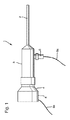
図1は、光学系を有する管状軸部2を遠位端に有している内視鏡1の略側面図を示している。侵襲を最小限に抑えた手術又は検査の間、この管状軸部2は、体にある開口を通じて体腔内へと挿入されている。管状軸部2はハウジング3へと通じており、ハウジング3は、近位端で、つまり外科医または操作者に向かって配置されている方の端部で、図示されていない接眼レンズを有する接眼部4へと通じている。ハウジング3も内視鏡1を取り扱う機能を備えている。
In the drawings, the same or similar types of elements and / or parts are denoted by the same reference numerals, and the description thereof is omitted.
FIG. 1 shows a schematic side view of an endoscope 1 having a
内視鏡1のハウジング3側では、明光をハウジング3側から内視鏡1の光学系へと導入する光源5、特にLED光源が配置されており、ここから導入された光は、術野を照らすために、遠位端、つまり管状軸部2の先端で出射する。光源5は接続ケーブル5aを有している。通常の光学系の場合、光源5は、接続ケーブル5aとしてガラス繊維束が取り付けられているアダプタであり得る。ガラス繊維束を介して伝わってきた光は、次にアダプタを用いて内視鏡1に導入される。代替構造では、例えばLEDやハロゲン発光体等をベースとした活性光源5が存在していて、この場合、接続ケーブル5aは電流供給ケーブルである。
On the housing 3 side of the endoscope 1, a light source 5 that introduces bright light from the housing 3 side to the optical system of the endoscope 1, particularly an LED light source, is disposed. In order to illuminate, it exits at the distal end, ie the tip of the
模式的に示されているカメラヘッド6は、図示されていない接眼レンズアダプタを有し、カメラヘッド6は、内視鏡1の接眼部4に配置されており、内視鏡1の接眼レンズから出射する光を、自身の光学系を用いて捕らえて、その光を光エリアセンサ、例えばCCDチップ上に集光する。カメラヘッド6のコネクタ6aを用いて、カメラヘッド6に電流を供給し、エリアセンサからの画像信号を外部の評価ユニットへと伝達し、制御信号をカメラヘッド6へと伝達する。
The camera head 6 schematically shown has an eyepiece lens adapter (not shown), and the camera head 6 is disposed in the eyepiece 4 of the endoscope 1, and the eyepiece of the endoscope 1. The light emitted from the light is captured using its own optical system, and the light is collected on an optical area sensor, for example, a CCD chip. A current is supplied to the camera head 6 using the
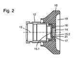
図2は、接眼レンズの断面を、内視鏡の近位側での断面で模式的に示したものである。接眼レンズは、例えば光学アセンブリとして撮像レンズ(図示せず)が配置されている接眼レンズ台12を有している。接眼レンズは、光学アセンブリの光軸13を有している。
FIG. 2 schematically shows a cross section of the eyepiece in a cross section on the proximal side of the endoscope. The eyepiece has an eyepiece table 12 on which an imaging lens (not shown) is disposed as an optical assembly, for example. The eyepiece has an
接眼レンズ窓台とも称されている接眼レンズ台12の近位端では、光学平板14が、接眼レンズ窓として配置されている。光学平板14は、凹部が設けられているユニオンナット16内に収容されている。ユニオンナット16は、接眼レンズ台12のおねじと噛み合うめねじを有している。さらに、接眼部18は、接眼レンズ台12上にある内視鏡の近位側に配置されており、接眼部凹部19を有している。
At the proximal end of the eyepiece table 12, also referred to as an eyepiece window table, an
ユニオンナット16によって保持されている光学平板14は、互いに平行な位置にある入光側15.1と出光側15.2とを有している。入光側15.1と出光側15.2は、光軸13に対して90°ではない角度となる位置にある。光軸13は接眼レンズの機械軸と同一線上にある。
The optical
光学平板14の表面法線が光軸に対して6°の角度になるような位置にするために、光学平板14は段状留め部17を有している。接眼レンズ台12の近位開口部に接触する平面は、段状平坦接触部である周囲の段状留め部17によって設けられている。この場合の段状留め部17は、光学平板14の入光側15.1の面に対して、もしくは光学平板14の出光側15.2に対して、6°の角度になる位置にある。よって、互いに平行な光学平板14の入光側15.1と出光側15.2の各表面法線は、光軸13に対して6°の角度になる位置にある。
The optical
図3は、本発明に係る光学平板14の拡大図を模式的に描写している。
接眼レンズ台12に面する段状留め部17の段状接触部は、この場合、接眼レンズ台の光軸13または機械軸に直交するように位置している平面である。この場合、段状留め部17の近位側接触面は、ユニオンナット16の凹部内において相補的な形状で構成されている。
FIG. 3 schematically depicts an enlarged view of the
In this case, the stepped contact portion of the stepped
ユニオンナット16はプラスチックでできていることが好ましく、光学平板14の出光側15.2上に内側斜面が形成されていて、これにより、ユニオンナット16は近位側に凹部21を有していることがさらに好ましい。ユニオンナット16は、近位側において、凹部21が、光学平板14と近位側表面との境界となる領域、つまり、光学平板14の出光側15.2と同一平面になるような位置にあるように設計されている。光学平板14の近位出光側15.2が光学平板14に接して取り囲む凹部21の周縁部と同一平面になるような位置関係にある場合は、光学平板14の周縁部と凹部21との間には妨げになる端部などなく移行するような構成になり、これにより、光学平板14と光学平板14を囲む凹部21との間で高さが急激に変わることが防げる。
The union nut 16 is preferably made of plastic, and an inner inclined surface is formed on the light output side 15.2 of the optical
1 内視鏡、2 光学系を有する管状軸部、3 ハウジング、4 接眼部、5 光源、5a 光源用接続ケーブル、6 カメラヘッド、6a カメラヘッドのコネクタ、12 接眼レンズ台、14 光学平板、15.1 入光側、15.2 出光側、16 ユニオンナット、17 段状留め部、18 接眼部、19 接眼部凹部、21 凹部 DESCRIPTION OF SYMBOLS 1 Endoscope, 2 Tubular axial part which has an optical system, 3 Housing, 4 Eyepiece part, 5 Light source, 5a Connection cable for light sources, 6 Camera head, 6a Connector of camera head, 12 Eyepiece stand, 14 Optical plate, 15.1 Light-incident side, 15.2 Light-emitting side, 16 Union nut, 17 Stepped fastener, 18 Eyepiece, 19 Eyepiece recess, 21 Recess
Claims (11)
前記幅広側縁部(17)が設けられる前記光学平板(14)の周面が、前記接眼レンズ台(12)に面する前記光学平板(14)の前記幅広側縁部(17)の前記接触面の法線の方向に沿って延在することを特徴とする、接眼レンズ装置。 An eyepiece device for a surgical instrument (1) having an eyepiece base (12) for an optical assembly, wherein an optical plate (14) is housed in a holder (16) , said optical The holder (16) of the flat plate (14) is an eyepiece device that can be connected to or connected to the eyepiece table (12), and has a wide side edge (17) of the optical flat plate (14). Is provided with a contact surface to the eyepiece table (12) and a contact surface to the holder, and faces the surface normal of the optical flat plate (14) and the eyepiece table (12). wherein a normal line of the contact surface of the wide edge of the optical plate (14) (17), Ri positional relationship near an angle of 2.0 ° or more with respect to each other,
The contact of the wide side edge (17) of the optical flat plate (14) with the peripheral surface of the optical flat plate (14) provided with the wide side edge (17) facing the eyepiece lens base (12). wherein the extension Mashimasu isosamples along the direction of the normal of the surface, an eyepiece system.
Applications Claiming Priority (3)
| Application Number | Priority Date | Filing Date | Title |
|---|---|---|---|
| DE102015202137.8 | 2015-02-06 | ||
| DE102015202137.8A DE102015202137A1 (en) | 2015-02-06 | 2015-02-06 | Eyepiece for a surgical instrument |
| PCT/EP2016/050752 WO2016124370A1 (en) | 2015-02-06 | 2016-01-15 | Eyepiece for a surgical instrument |
Publications (3)
| Publication Number | Publication Date |
|---|---|
| JP2018507035A JP2018507035A (en) | 2018-03-15 |
| JP2018507035A5 JP2018507035A5 (en) | 2018-04-26 |
| JP6590934B2 true JP6590934B2 (en) | 2019-10-16 |
Family
ID=55173831
Family Applications (1)
| Application Number | Title | Priority Date | Filing Date |
|---|---|---|---|
| JP2017541264A Active JP6590934B2 (en) | 2015-02-06 | 2016-01-15 | Surgical instrument eyepiece |
Country Status (5)
| Country | Link |
|---|---|
| US (1) | US10595713B2 (en) |
| EP (1) | EP3253271B1 (en) |
| JP (1) | JP6590934B2 (en) |
| DE (1) | DE102015202137A1 (en) |
| WO (1) | WO2016124370A1 (en) |
Families Citing this family (2)
| Publication number | Priority date | Publication date | Assignee | Title |
|---|---|---|---|---|
| DE102017122225A1 (en) * | 2017-09-26 | 2019-03-28 | Olympus Winter & Ibe Gmbh | endoscope |
| DE102018102385A1 (en) | 2018-02-02 | 2019-08-08 | Olympus Winter & Ibe Gmbh | Eyepiece device for a surgical instrument |
Family Cites Families (15)
| Publication number | Priority date | Publication date | Assignee | Title |
|---|---|---|---|---|
| JPS5840721B2 (en) * | 1979-03-05 | 1983-09-07 | オリンパス光学工業株式会社 | Eyepiece positioning device |
| JPS5895317A (en) * | 1981-11-30 | 1983-06-06 | Olympus Optical Co Ltd | Eyepiece device of endoscope |
| JPS58163917U (en) * | 1982-04-24 | 1983-11-01 | オリンパス光学工業株式会社 | Endoscope cover glass attachment device |
| JPS6015618A (en) * | 1983-07-08 | 1985-01-26 | Olympus Optical Co Ltd | Endoscope |
| EP0170008A3 (en) * | 1984-07-04 | 1987-12-16 | Elesta Ag Elektronik | Light pen or barrier |
| JPH0532822Y2 (en) * | 1986-05-21 | 1993-08-23 | ||
| JPH04109926A (en) * | 1990-08-31 | 1992-04-10 | Fukuda Denshi Co Ltd | Optical axis adjusting method for blood vessel endoscoping catheter |
| US5125394A (en) * | 1990-12-03 | 1992-06-30 | Medical Concepts, Inc. | Endoscopic adapter with lamina interface |
| DE4403566A1 (en) * | 1994-02-07 | 1995-08-10 | Wolf Gmbh Richard | Endoscopic instrument |
| US6025873A (en) * | 1994-04-07 | 2000-02-15 | Olympus Optical Co., Ltd. | Endoscope system provided with low-pass filter for moire removal |
| JP2002357786A (en) * | 2001-05-30 | 2002-12-13 | Kyocera Corp | Optical device and method for assembling the same |
| JP4027089B2 (en) * | 2001-12-26 | 2007-12-26 | アルプス電気株式会社 | Frame with optical filter and method for manufacturing the same |
| WO2013009970A1 (en) * | 2011-07-13 | 2013-01-17 | Viking Systems, Inc | Method and apparatus for obtaining stereoscopic 3d visualization using commercially available 2d endoscopes |
| DE102012011717A1 (en) | 2012-06-14 | 2013-12-19 | Karl Storz Gmbh & Co. Kg | Optical instrument |
| JP6465439B2 (en) * | 2015-06-17 | 2019-02-06 | オリンパス株式会社 | Endoscopic imaging device |
-
2015
- 2015-02-06 DE DE102015202137.8A patent/DE102015202137A1/en not_active Ceased
-
2016
- 2016-01-15 JP JP2017541264A patent/JP6590934B2/en active Active
- 2016-01-15 WO PCT/EP2016/050752 patent/WO2016124370A1/en active Application Filing
- 2016-01-15 EP EP16700813.5A patent/EP3253271B1/en active Active
-
2017
- 2017-07-27 US US15/661,179 patent/US10595713B2/en active Active
Also Published As
| Publication number | Publication date |
|---|---|
| EP3253271A1 (en) | 2017-12-13 |
| JP2018507035A (en) | 2018-03-15 |
| EP3253271B1 (en) | 2019-03-06 |
| WO2016124370A1 (en) | 2016-08-11 |
| US10595713B2 (en) | 2020-03-24 |
| DE102015202137A1 (en) | 2016-08-11 |
| US20170332885A1 (en) | 2017-11-23 |
Similar Documents
| Publication | Publication Date | Title |
|---|---|---|
| US9930294B2 (en) | Handpiece with built-in camera and dental treatment method using handpiece | |
| JP4668831B2 (en) | Endoscope | |
| JP2015533300A (en) | Multi-camera endoscope | |
| US20210275006A1 (en) | Micro endoscope camera module and micro endoscope having same | |
| JP6590934B2 (en) | Surgical instrument eyepiece | |
| CN110996749B (en) | 3D video endoscope | |
| JP2009273652A (en) | Endoscope system and connector cover | |
| WO2006004124A1 (en) | Endoscope | |
| JP6738465B2 (en) | Endoscope system | |
| KR101516318B1 (en) | Endoscopy lighting module improving light efficiency | |
| JP6868899B2 (en) | Dental endoscope | |
| JP7131781B2 (en) | Trocar with imaging function | |
| JP2017113079A (en) | Objective optical unit | |
| JP6439081B2 (en) | Endoscope | |
| US20190290113A1 (en) | Endoscope apparatus and medical imaging device | |
| KR20160056704A (en) | head cap for endoscope | |
| JP7078797B2 (en) | Endoscope connector device | |
| JP6600093B2 (en) | Endoscope optical adapter attachment / detachment aid and endoscope system | |
| JP6116381B2 (en) | Endoscope system | |
| US20220151476A1 (en) | Mount member and endoscope device | |
| JP4895630B2 (en) | Endoscope device for magnification observation | |
| JP6464106B2 (en) | Endoscopic imaging apparatus and endoscope | |
| US10401612B2 (en) | Endoscope | |
| JP6700941B2 (en) | Endoscope device | |
| JP2022038180A5 (en) |
Legal Events
| Date | Code | Title | Description |
|---|---|---|---|
| A521 | Request for written amendment filed |
Free format text: JAPANESE INTERMEDIATE CODE: A523 Effective date: 20180302 |
|
| A621 | Written request for application examination |
Free format text: JAPANESE INTERMEDIATE CODE: A621 Effective date: 20180302 |
|
| A977 | Report on retrieval |
Free format text: JAPANESE INTERMEDIATE CODE: A971007 Effective date: 20181130 |
|
| A131 | Notification of reasons for refusal |
Free format text: JAPANESE INTERMEDIATE CODE: A131 Effective date: 20181225 |
|
| A521 | Request for written amendment filed |
Free format text: JAPANESE INTERMEDIATE CODE: A523 Effective date: 20190312 |
|
| TRDD | Decision of grant or rejection written | ||
| A01 | Written decision to grant a patent or to grant a registration (utility model) |
Free format text: JAPANESE INTERMEDIATE CODE: A01 Effective date: 20190827 |
|
| A61 | First payment of annual fees (during grant procedure) |
Free format text: JAPANESE INTERMEDIATE CODE: A61 Effective date: 20190917 |
|
| R150 | Certificate of patent or registration of utility model |
Ref document number: 6590934 Country of ref document: JP Free format text: JAPANESE INTERMEDIATE CODE: R150 |
|
| R250 | Receipt of annual fees |
Free format text: JAPANESE INTERMEDIATE CODE: R250 |