JP6544700B2 - Control device and work management system using the same - Google Patents

Control device and work management system using the same Download PDF

Info

Publication number
JP6544700B2
JP6544700B2 JP2018126628A JP2018126628A JP6544700B2 JP 6544700 B2 JP6544700 B2 JP 6544700B2 JP 2018126628 A JP2018126628 A JP 2018126628A JP 2018126628 A JP2018126628 A JP 2018126628A JP 6544700 B2 JP6544700 B2 JP 6544700B2
Authority
JP
Japan
Prior art keywords
work
control device
management system
torque
tool
Prior art date
Legal status (The legal status is an assumption and is not a legal conclusion. Google has not performed a legal analysis and makes no representation as to the accuracy of the status listed.)
Active
Application number
JP2018126628A
Other languages
Japanese (ja)
Other versions
JP2018149677A (en
Inventor
小林 浩治
浩治 小林
Current Assignee (The listed assignees may be inaccurate. Google has not performed a legal analysis and makes no representation or warranty as to the accuracy of the list.)
Panasonic Intellectual Property Management Co Ltd
Original Assignee
Panasonic Intellectual Property Management Co Ltd
Priority date (The priority date is an assumption and is not a legal conclusion. Google has not performed a legal analysis and makes no representation as to the accuracy of the date listed.)
Filing date
Publication date
Application filed by Panasonic Intellectual Property Management Co Ltd filed Critical Panasonic Intellectual Property Management Co Ltd
Priority to JP2018126628A priority Critical patent/JP6544700B2/en
Publication of JP2018149677A publication Critical patent/JP2018149677A/en
Priority to JP2019106956A priority patent/JP6895630B2/en
Application granted granted Critical
Publication of JP6544700B2 publication Critical patent/JP6544700B2/en
Active legal-status Critical Current
Anticipated expiration legal-status Critical

Links

Images

Classifications

    • YGENERAL TAGGING OF NEW TECHNOLOGICAL DEVELOPMENTS; GENERAL TAGGING OF CROSS-SECTIONAL TECHNOLOGIES SPANNING OVER SEVERAL SECTIONS OF THE IPC; TECHNICAL SUBJECTS COVERED BY FORMER USPC CROSS-REFERENCE ART COLLECTIONS [XRACs] AND DIGESTS
    • Y02TECHNOLOGIES OR APPLICATIONS FOR MITIGATION OR ADAPTATION AGAINST CLIMATE CHANGE
    • Y02PCLIMATE CHANGE MITIGATION TECHNOLOGIES IN THE PRODUCTION OR PROCESSING OF GOODS
    • Y02P90/00Enabling technologies with a potential contribution to greenhouse gas [GHG] emissions mitigation
    • Y02P90/02Total factory control, e.g. smart factories, flexible manufacturing systems [FMS] or integrated manufacturing systems [IMS]

Landscapes

  • Details Of Spanners, Wrenches, And Screw Drivers And Accessories (AREA)
  • General Factory Administration (AREA)

Description

本発明は、一般に制御装置、作業管理システム、より詳細には工具を用いた作業の管理を行う制御装置及びそれを用いた作業管理システムに関する。   The present invention generally relates to a control device, a work management system, and more particularly to a control device that manages work using a tool and a work management system using the same.

従来、ボルト等の締結部品を対象物の予め決められた位置に締め付ける作業において、締め忘れを防ぐための機器や機構を備えた締付工具や締付管理システムが知られており、例えば特許文献1に開示されている。特許文献1に記載の締付管理システムは、締付工具であるトルクレンチと、締付位置情報を管理する管理装置とを備えている。   Conventionally, in an operation of tightening a fastening part such as a bolt at a predetermined position of an object, a tightening tool and a tightening management system provided with a device and a mechanism for preventing forgetting tightening are known. 1 is disclosed. The tightening management system described in Patent Document 1 includes a torque wrench, which is a tightening tool, and a management device that manages tightening position information.

トルクレンチは、締結部品を締め付けた締付トルクを無線通信により管理装置に出力する。また、トルクレンチは、トルクレンチを移動させた場合に、加速度センサ、ジャイロセンサ、地磁気センサから出力される信号に基づいて締付位置を特定し、その締付位置を示す締付位置情報を無線などの通信媒体により管理装置に出力する。管理装置は、トルクレンチから出力された締付位置情報と、締付トルクとを通信媒体により取得し、取得した締付位置情報及び締付トルクを管理する。   The torque wrench outputs the tightening torque for tightening the fastening parts to the management device by wireless communication. Also, when the torque wrench is moved, the tightening position is specified based on the signals output from the acceleration sensor, the gyro sensor, and the geomagnetic sensor, and the tightening position information indicating the tightening position is wirelessly transmitted. Output to the management device using a communication medium such as The management device acquires the tightening position information output from the torque wrench and the tightening torque by the communication medium, and manages the acquired tightening position information and the tightening torque.

特開2013−188858号公報JP, 2013-188858, A

しかしながら、上記従来例では、作業者が工具を用いて締結部品を締め付けた(すなわち、作業者が工具を用いて作業を行った)位置を知ることはできるが、工具を用いた作業の状態を把握することができないという問題があった。例えば、作業者が締結部品を締め付けたと思っていても、実際には締結部品が正しく締め付けられていない場合がある。このような場合、上記従来例では、締結部品が正しく締め付けられているか否かの状態(すなわち、工具を用いた作業の状態)を把握することができない。   However, in the above-described conventional example, although it is possible to know the position at which the operator tightens the fastening part using the tool (that is, the operator performs the operation using the tool), the state of the operation using the tool There was a problem that it was impossible to grasp. For example, even if the operator thinks that the fastening part is tightened, the fastening part may not actually be correctly tightened. In such a case, in the above-mentioned conventional example, it is not possible to grasp the state (i.e., the state of work using a tool) as to whether or not the fastening part is properly tightened.

本発明は、上記の点に鑑みて為されており、工具を用いた作業の状態を把握することのできる制御装置及びそれを用いた作業管理システムを提供することを目的とする。   The present invention is made in view of the above-mentioned point, and an object of the present invention is to provide a control device which can grasp a state of work using a tool and a work management system using the same.

本発明の制御装置は、締結部品を締め付ける作業の際に用いられる工具との間、及び前記作業が行われる作業箇所を撮像する撮像装置との間でそれぞれ通信を行う通信部と、前記工具により前記締結部品に与えられる締付トルクと、前記撮像装置により撮像された撮像画像とに基づいて、前記締結部品が正しく締め付けられているか否かを判定する判定処理を実行する処理部とを備え、前記処理部は、前記判定処理において、前記作業で要求される目標トルクと前記締付トルクとの比較結果と、前記作業箇所において前記締結部品が正常に締め付けられた状態を示す目標画像と前記撮像画像との比較結果とに基づいて、前記締結部品が正しく締め付けられているか否かを判定することを特徴とする。   The control device according to the present invention includes a communication unit for performing communication with a tool used in an operation of tightening a fastening part and an imaging device for imaging an operation place where the operation is performed, and the tool A processing unit configured to execute a determination process of determining whether or not the fastening component is properly tightened based on a tightening torque given to the fastening component and a captured image captured by the imaging device; In the determination process, the processing unit compares the target torque required in the operation with the tightening torque, and the target image and the image showing a state in which the fastening component is normally tightened at the work location. It is characterized by judging whether the above-mentioned fastening part is correctly tightened based on a comparison result with a picture.

本発明の作業管理システムは、上記の制御装置と、前記締付トルクのデータを前記制御装置に向けて送信する通信部を有する前記工具と、前記撮像装置及び前記撮像画像のデータを前記制御装置に向けて送信する通信装置を有するウェアラブル端末とを備えることを特徴とする。   The work management system according to the present invention includes the tool described above, and the tool having a communication unit for transmitting data of the tightening torque to the control device, the image pickup device, and data of the captured image as the control device. And a wearable terminal having a communication device for transmitting toward the terminal.

本発明は、工具を用いた作業の状態を把握することができる。   The present invention can grasp the state of work using a tool.

実施形態に係る制御装置及び作業管理システムの概略ブロック図である。It is a schematic block diagram of a control device and a work management system concerning an embodiment. 実施形態に係る作業管理システムの一例を示す概略図である。It is a schematic diagram showing an example of a work management system concerning an embodiment. 実施形態に係る作業管理システムにおける工具の一例を示す概略図である。It is the schematic which shows an example of the tool in the work management system which concerns on embodiment. 実施形態に係る作業管理システムにおける工具の一例を示す概略図である。It is the schematic which shows an example of the tool in the work management system which concerns on embodiment. 実施形態に係る作業管理システムの動作を示すフローチャート図である。It is a flowchart figure which shows operation | movement of the work management system which concerns on embodiment. 図6Aは、実施形態に係る作業管理システムにおいて、ねじが正常に締め付けられている状態を示す図で、図6Bは、実施形態に係る作業管理システムにおいて、ねじが正常に締め付けられていない状態を示す図である。FIG. 6A is a view showing a state in which the screw is normally tightened in the operation management system according to the embodiment, and FIG. 6B is a view showing a state in which the screw is not properly tightened in the operation management system according to the embodiment FIG. 図7Aは、部品管理システムの概略図で、図7Bは、実施形態に係る作業管理システムを適用した部品管理システムの概略ブロック図である。FIG. 7A is a schematic view of a parts management system, and FIG. 7B is a schematic block diagram of a parts management system to which a work management system according to an embodiment is applied.

本発明の実施形態に係る制御装置2は、図1,図2に示すように、通信部23と、処理部24とを備えている。通信部23は、締結部品(例えば、ねじ10)を締め付ける作業の際に用いられる工具3との間、及び作業が行われる作業箇所を撮像する撮像装置41との間でそれぞれ通信を行う。処理部24は、工具3により締結部品に与えられる締付トルクと、撮像装置41により撮像された撮像画像とに基づいて、作業が正常に行われているか否かを判定する判定処理を実行する。   The control apparatus 2 which concerns on embodiment of this invention is provided with the communication part 23 and the process part 24 as shown to FIG. 1, FIG. The communication unit 23 communicates with the tool 3 used in the operation of tightening the fastening part (for example, the screw 10) and with the imaging device 41 which images the work location where the operation is performed. The processing unit 24 performs a determination process of determining whether the work is normally performed based on the tightening torque applied to the fastening part by the tool 3 and the captured image captured by the imaging device 41. .

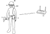
また、本発明の実施形態に係る作業管理システム1は、図1,図2に示すように、本実施形態の制御装置2と、工具3と、ウェアラブル端末(wearable device)4とを備えている。工具3は、締付トルクのデータを制御装置2に向けて送信する通信部32を有する。ウェアラブル端末4は、撮像装置41及び撮像画像のデータを制御装置2に向けて送信する通信装置43を有する。   The work management system 1 according to the embodiment of the present invention, as shown in FIGS. 1 and 2, includes the control device 2 of the present embodiment, the tool 3 and the wearable device 4. . The tool 3 has a communication unit 32 that transmits data of the tightening torque toward the control device 2. The wearable terminal 4 includes an imaging device 41 and a communication device 43 that transmits data of a captured image to the control device 2.

以下、本実施形態の制御装置2及び作業管理システム1について詳細に説明する。但し、以下に説明する構成は、本発明の一例に過ぎず、本発明は下記の実施形態に限定されることはなく、この実施形態以外であっても、本発明に係る技術的思想を逸脱しない範囲であれば、設計等に応じて種々の変更が可能である。   Hereinafter, the control device 2 and the work management system 1 of the present embodiment will be described in detail. However, the configuration described below is only an example of the present invention, and the present invention is not limited to the following embodiment, and even if it is other than this embodiment, it deviates from the technical idea according to the present invention. If it is not within the range, various changes can be made according to the design and the like.

本実施形態の作業管理システム1は、図1に示すように、制御装置2と、工具3と、ウェアラブル端末4とを備えている。また、本実施形態の作業管理システム1は、制御装置2との間で通信を行う上位装置5を備えている。   The work management system 1 of the present embodiment includes a control device 2, a tool 3 and a wearable terminal 4 as shown in FIG. 1. Further, the work management system 1 of the present embodiment is provided with a host device 5 that communicates with the control device 2.

制御装置2は、表示部21と、記憶部22と、通信部23と、処理部24とを備えている。表示部21は、例えば液晶ディスプレイや有機EL(Electro-Luminescence)ディスプレイ等で構成されており、作業者W1に対する指示内容などの各種情報を文字及び画像の少なくとも一方を用いて表示する。本実施形態の制御装置2では、表示部21は、タッチパネル型の液晶ディスプレイで構成されている。   The control device 2 includes a display unit 21, a storage unit 22, a communication unit 23, and a processing unit 24. The display unit 21 is configured of, for example, a liquid crystal display, an organic EL (Electro-Luminescence) display, or the like, and displays various information such as instruction content for the operator W1 using at least one of a character and an image. In the control device 2 of the present embodiment, the display unit 21 is configured of a touch panel liquid crystal display.

記憶部22は、例えばEEPROM(Electrically Erasable Programmable Read-Only Memory)やフラッシュメモリで構成されており、処理部24で起動するアプリケーション等の各種情報を記憶する。また、記憶部22は、工具3から送信される締付トルクのデータと、ウェアラブル端末4で撮像された撮像画像のデータとを作業箇所毎に記憶する。その他、記憶部22は、締結部品を締め付ける際に要求されるトルク(目標トルク)と、作業者W1が作業を行うべき作業箇所を示す画像(指示画像)のデータと、締結部品が正常に締め付けられた状態を示す画像(目標画像)とを作業箇所毎に記憶する。なお、締結部品とは、例えばねじ10(図6A参照)やボルト等の部材である。   The storage unit 22 is composed of, for example, an EEPROM (Electrically Erasable Programmable Read-Only Memory) or a flash memory, and stores various information such as an application activated by the processing unit 24. In addition, the storage unit 22 stores data of tightening torque transmitted from the tool 3 and data of a captured image captured by the wearable terminal 4 for each work location. In addition, the storage unit 22 properly tightens the fastening parts such as torque (target torque) required when tightening the fastening parts, data of an image (instruction image) indicating the work location where the operator W1 is to work, and An image (a target image) indicating the selected state is stored for each work location. The fastening part is, for example, a member such as a screw 10 (see FIG. 6A) or a bolt.

記憶部22で記憶するデータの一例を表1に示す。表1は、作業者W1が締結部品としてねじ10を締め付ける作業を行う場合のデータを表している。表1において、「番号」は、それぞれ作業者W1が作業を行う作業箇所毎に付された番号である。また、「規格」は、作業箇所毎に要求される締結部品の規格(例えば、‘M8’,‘M10’等)である。   An example of data stored in the storage unit 22 is shown in Table 1. Table 1 represents data when the worker W1 performs an operation of tightening the screw 10 as a fastening part. In Table 1, "number" is a number assigned to each work location where the worker W1 works. "Standard" is a standard of a fastening part (for example, 'M8', 'M10', etc.) required for each work place.

Figure 0006544700
Figure 0006544700

通信部23は、有線通信の規格及び無線通信の規格(例えば、Bluetooth(登録商標)やWiFi(登録商標))に対応した通信モジュールで構成されている。本実施形態の制御装置2では、通信部23は、工具3との間、及び上位装置5との間ではそれぞれ無線通信を行い、ウェアラブル端末4との間ではケーブルCA1(図2参照)を介して有線通信を行っている。勿論、通信部23は、ウェアラブル端末4との間でも無線通信を行ってもよいし、工具3との間、及び上位装置5との間でそれぞれケーブル(図示せず)を介して有線通信を行ってもよい。   The communication unit 23 is configured of a communication module compatible with the standard of wired communication and the standard of wireless communication (for example, Bluetooth (registered trademark) or WiFi (registered trademark)). In the control device 2 of the present embodiment, the communication unit 23 performs wireless communication with the tool 3 and with the host device 5, respectively, and with the wearable terminal 4 via the cable CA1 (see FIG. 2). Wired communication. Of course, the communication unit 23 may perform wireless communication with the wearable terminal 4 or wire communication with the tool 3 and with the higher-level device 5 via cables (not shown). You may go.

処理部24は、例えばCPU(Central Processing Unit)で構成されており、記憶部22に記憶されているアプリケーションを起動することで各種処理を実現する。具体的には、処理部24は、記憶部22から指示内容のデータを読み出してウェアラブル端末4に向けて指示信号を送信する処理を実行する。また、処理部24は、工具3により締結部品に与えられる締付トルクと、ウェアラブル端末4で撮像された撮像画像とに基づいて、作業者W1による作業が正常に行われているか否かを判定する判定処理を実行する。判定処理の詳細については後述する。   The processing unit 24 is configured by, for example, a CPU (Central Processing Unit), and realizes various processes by activating an application stored in the storage unit 22. Specifically, the processing unit 24 executes a process of reading out the data of the instruction content from the storage unit 22 and transmitting the instruction signal to the wearable terminal 4. In addition, the processing unit 24 determines whether the work by the worker W1 is normally performed based on the tightening torque applied to the fastening part by the tool 3 and the captured image captured by the wearable terminal 4 Execute judgment processing. Details of the determination process will be described later.

本実施形態の制御装置2は、図2に示すように、タブレット型の携帯端末で構成されている。したがって、本実施形態の制御装置2は、作業者W1が携帯しながら作業を行うことが可能であり、利便性に優れている。勿論、制御装置2をタブレット型の携帯端末に限定する趣旨ではない。例えば、制御装置2は、スマートフォンで構成されていてもよい。また、制御装置2は、携帯端末の他にも、PLC(Programmable Logic Controller:プログラマブルロジックコントローラ)や、PC(Personal Computer:パーソナルコンピュータ)等で構成されていてもよい。更に、制御装置2は、少なくとも通信部23と処理部24とを備えていればよく、表示部21及び記憶部22を備えるか否かは任意である。例えば、制御装置2は、表示部21を備えずに、作業者W1に対する作業の指示内容を音声で出力する音声出力部(図示せず)を備えていてもよい。勿論、制御装置2は、音声出力部と表示部21との両方を備えていてもよい。   As shown in FIG. 2, the control device 2 of the present embodiment is configured of a tablet type portable terminal. Therefore, the control device 2 of the present embodiment can perform work while the worker W1 carries it, and is excellent in convenience. Of course, it is not the meaning which limits control device 2 to a tablet type portable terminal. For example, the control device 2 may be configured by a smartphone. In addition to the portable terminal, the control device 2 may be configured by a PLC (Programmable Logic Controller), a PC (Personal Computer), or the like. Furthermore, the control device 2 only needs to include at least the communication unit 23 and the processing unit 24, and whether or not the display unit 21 and the storage unit 22 are provided is optional. For example, the control device 2 may not include the display unit 21 and may include an audio output unit (not shown) that outputs the instruction content of the work to the worker W1 by voice. Of course, the control device 2 may include both the audio output unit and the display unit 21.

工具3は、締結部品に所定のトルクを与えることで、締結部品をワーク11(図6A参照)に締め付けるように構成されている。なお、ワーク11は、例えば木板や鉄板のように、作業(ここでは、締結部品を締め付ける作業)の対象となる部材を表す。工具3は、図1に示すように、締結部品に与えられる締付トルクを測定する測定部31と、制御装置2との間で通信を行う通信部32とを備えている。   The tool 3 is configured to clamp the fastening component to the work 11 (see FIG. 6A) by applying a predetermined torque to the fastening component. In addition, the workpiece | work 11 represents the member used as the object of operation | work (here, operation | work which clamps a fastening component) like a wood board or an iron plate. The tool 3 is provided with the measurement part 31 which measures the fastening torque given to a fastening component, and the communication part 32 which communicates between the control apparatuses 2, as shown in FIG.

工具3としては、例えばトルクレンチや、電動式のインパクトドライバ等が挙げられる。その他、工具3としては、電動式のインパクトレンチなどが挙げられる。なお、インパクトドライバやインパクトレンチは、電動式でなくてもよく、例えば圧縮空気を動力源とした工具であってもよい。更に、工具3は、手動式のスクリュードライバであってもよい。何れの工具3でも、通信部32を有している。なお、工具3は測定部31を有している必要はない。工具3が測定部31を有さない場合は、例えばトルクリミッタ(後述する)で設定された設定トルクを締付トルクとして制御装置2に送信してもよい。   Examples of the tool 3 include a torque wrench, an electric impact driver, and the like. In addition, as the tool 3, an electric impact wrench etc. are mentioned. The impact driver and the impact wrench may not be motorized, and may be, for example, a tool using compressed air as a power source. Furthermore, the tool 3 may be a manual screwdriver. Each tool 3 has the communication unit 32. The tool 3 does not have to have the measuring unit 31. When the tool 3 does not have the measurement unit 31, for example, a set torque set by a torque limiter (described later) may be transmitted to the control device 2 as a tightening torque.

以下、工具3の例として、トルクレンチ300及びインパクトドライバ310について図面を用いて簡単に説明する。   Hereinafter, a torque wrench 300 and an impact driver 310 will be briefly described using drawings as an example of the tool 3.

トルクレンチ300は、図3に示すように、ヘッド301と、腕部303と、把持部304と、ケース308とを備えている。また、腕部303の内部には、磁歪式のロードセル(検出部)305が設けられている。また、ケース308の内部には、CPU(トルク演算部)306と、通信I/F(インタフェース)307とが収納されている。   As shown in FIG. 3, the torque wrench 300 includes a head 301, an arm portion 303, a grip portion 304, and a case 308. Also, inside the arm portion 303, a magnetostrictive load cell (detection unit) 305 is provided. Further, inside the case 308, a CPU (torque calculation unit) 306 and a communication I / F (interface) 307 are accommodated.

ヘッド301は、作業者W1による締め付け作業の際に、回転中心となる部位である。ヘッド301には、ソケット302Aが取り付けられる差込角302が設けられている。ソケット302Aは、例えばボルト等の締結部品に嵌める部材である。このソケット302Aを差込角302に取り付けた状態でソケット302Aを締結部品に嵌め、ヘッド301を回転させることにより締結部品に所定のトルクを与えることが可能となる。言い換えれば、ヘッド301は、締結部品の規格に応じたソケット302Aが装着され、回転によりソケット302Aを介して締結部品にトルクを与える。なお、差込角302には、締結部品の規格に応じたソケット302Aを適宜取り付けることができる。   The head 301 is a portion serving as a rotation center at the time of tightening work by the worker W1. The head 301 is provided with a plug-in angle 302 to which the socket 302A is attached. The socket 302A is a member fitted to a fastening part such as a bolt, for example. With the socket 302A attached to the plug-in angle 302, the socket 302A is fitted to the fastening component, and the head 301 can be rotated to apply a predetermined torque to the fastening component. In other words, the head 301 is mounted with the socket 302A conforming to the standard of the fastening part, and applies torque to the fastening part via the socket 302A by rotation. In addition, the socket 302A according to the specification of a fastening component can be attached to the plug-in angle 302 suitably.

把持部304は、締結部品を締め付ける際に作業者W1が握る部材であり、作業者W1が握り易い形状に形成されている。腕部303は、把持部304に加えられた力を、ヘッド301を介して締結部品に伝達する棒状の部材である。腕部303の内部には、トルクリミッタ(図示せず)が設けられている。   The grip portion 304 is a member gripped by the worker W1 when the fastening part is tightened, and is formed in a shape that the worker W1 can easily grip. The arm portion 303 is a rod-like member that transmits the force applied to the grip portion 304 to the fastening component via the head 301. Inside the arm portion 303, a torque limiter (not shown) is provided.

トルクリミッタは、締結部品に加えられるトルクが予め設定されている設定トルクに達すると作動し、過大なトルクが締結部品に加えられないように制限する機構である。なお、トルクリミッタは従来周知の機構であるので、ここでは詳細な説明を省略する。また、トルクリミッタが作動する設定トルクは、例えば調整摘み(図示せず)により設定することが可能である。このような調整摘みも従来周知であるので、ここでは詳細な説明を省略する。   The torque limiter is a mechanism that operates when the torque applied to the fastening component reaches a preset set torque, and limits so that an excessive torque is not applied to the fastening component. In addition, since a torque limiter is a conventionally well-known mechanism, detailed description is abbreviate | omitted here. Further, the set torque at which the torque limiter operates can be set, for example, by an adjustment knob (not shown). Such adjustment control is also well known in the prior art, and thus the detailed description is omitted here.

ロードセル305は、歪ゲージ(図示せず)を備えている。ロードセル305は、締結部品を締め付ける際に加えられるトルクに応じて僅かに変形する。そして、ロードセル305は、変形することで生じる歪みを歪ゲージにて検出し、この歪みに比例した電気信号をCPU306に出力する。つまり、ロードセル305は、締結部品に加えられるトルクに応じた電気信号を出力する。CPU306は、ロードセル305の出力する電気信号に基づいて、締付トルクを演算する。つまり、トルクレンチ300において、ロードセル305及びCPU306が測定部31に相当する。   The load cell 305 includes a strain gauge (not shown). The load cell 305 deforms slightly in response to the torque applied when tightening the fasteners. Then, the load cell 305 detects distortion caused by deformation with a strain gauge, and outputs an electrical signal proportional to this distortion to the CPU 306. That is, the load cell 305 outputs an electrical signal according to the torque applied to the fastening component. The CPU 306 calculates a tightening torque based on the electrical signal output from the load cell 305. That is, in the torque wrench 300, the load cell 305 and the CPU 306 correspond to the measurement unit 31.

通信I/F307は、無線通信の規格(例えば、Bluetooth(登録商標))に対応した通信モジュールで構成されている。ここでは、通信I/F307は、アンテナ(図示せず)を用いた無線通信により、CPU306で算出した締付トルクのデータを含む信号を制御装置2に向けて送信するように構成されている。つまり、トルクレンチ300において、通信I/F307が通信部32に相当する。なお、通信I/F307は、ケーブル(図示せず)を介した有線通信により、CPU306で算出した締付トルクのデータを含む信号を制御装置2に向けて送信するように構成されていてもよい。   The communication I / F 307 is configured of a communication module compatible with a wireless communication standard (for example, Bluetooth (registered trademark)). Here, the communication I / F 307 is configured to transmit a signal including data of the tightening torque calculated by the CPU 306 to the control device 2 by wireless communication using an antenna (not shown). That is, in the torque wrench 300, the communication I / F 307 corresponds to the communication unit 32. Communication I / F 307 may be configured to transmit a signal including data of the tightening torque calculated by CPU 306 to control device 2 by wired communication via a cable (not shown). .

なお、トルクレンチ300は、締付トルク等の情報を表示する液晶ディスプレイ(図示せず)を、ケース308の一面から露出する形で備えていてもよい。この構成では、作業者W1が締付トルクを直ぐに確認することができるので、好ましい。   The torque wrench 300 may be provided with a liquid crystal display (not shown) for displaying information such as a tightening torque in a form exposed from one surface of the case 308. This configuration is preferable because the worker W1 can immediately check the tightening torque.

インパクトドライバ310は、図4に示すように、インパクト機構311と、モータ312と、出力軸314と、磁歪式のトルクセンサ316(第1検出部)と、加速度センサ315(第2検出部)と、制御回路317(トルク演算部)とを備えている。また、インパクトドライバ310は、筒形状の胴部318と、胴部318の周面から出力軸314の軸方向と交差する向き(図4における下向き)に突出する握り部319とを備えている。   As shown in FIG. 4, the impact driver 310 includes an impact mechanism 311, a motor 312, an output shaft 314, a magnetostrictive torque sensor 316 (first detection unit), and an acceleration sensor 315 (second detection unit). , And a control circuit 317 (torque calculation unit). Further, the impact driver 310 includes a cylindrical body 318 and a grip 319 protruding from the circumferential surface of the body 318 in the direction intersecting the axial direction of the output shaft 314 (downward in FIG. 4).

握り部319の一端(図4における下端)には、樹脂製のケース内に充電池321を収納した電池パック320が着脱自在に取り付けられる。インパクトドライバ310は、この充電池321から供給される電力により動作する。具体的には、モータ312及び制御回路317の各々に充電池321から電線323,324を介して電力が供給されることで、インパクトドライバ310が動作する。   At one end (the lower end in FIG. 4) of the grip portion 319, a battery pack 320 containing a rechargeable battery 321 in a resin case is detachably attached. The impact driver 310 operates with the power supplied from the rechargeable battery 321. Specifically, the power is supplied to each of the motor 312 and the control circuit 317 from the rechargeable battery 321 through the electric wires 323 and 324, whereby the impact driver 310 operates.

また、握り部319には、作業者W1が押し込み可能な操作レバー325が設けられている。操作レバー325には、スイッチ回路(図示せず)が機械的に接続されている。スイッチ回路は、作業者W1による操作レバー325の押し込み操作に応じて、操作信号を制御回路317に出力するように構成されている。   Further, the grip portion 319 is provided with an operation lever 325 which can be pushed by the worker W1. A switch circuit (not shown) is mechanically connected to the operation lever 325. The switch circuit is configured to output an operation signal to the control circuit 317 in response to the pressing operation of the operation lever 325 by the worker W1.

インパクト機構311は、モータ312の軸313と連結されており、軸313の回転に応じてパルス状の衝撃力を発生させ、発生させた衝撃力を出力軸314に印加するように構成されている。つまり、インパクト機構311は、パルス状の衝撃力を発生させる。モータ312は、例えばブラシ付きのDC(Direct Current)モータ、またはブラシレスのDCモータで構成される。モータ312は、軸313が胴部318の軸線と一致するように、胴部318の内部に収納されている。モータ312には、制御回路317から電線324を介して駆動電流が供給される。また、モータ312の軸313の回転数や回転速度は、制御回路317により制御される。   The impact mechanism 311 is connected to the shaft 313 of the motor 312, and is configured to generate a pulse-like impact force according to the rotation of the shaft 313 and apply the generated impact force to the output shaft 314. . That is, the impact mechanism 311 generates a pulse-like impact force. The motor 312 is configured of, for example, a direct current (DC) motor with a brush or a brushless DC motor. The motor 312 is housed inside the body 318 such that the shaft 313 coincides with the axis of the body 318. A drive current is supplied to the motor 312 from the control circuit 317 via the electric wire 324. Further, the number of rotations and the rotation speed of the shaft 313 of the motor 312 are controlled by the control circuit 317.

出力軸314は、胴部318の軸線と一致するように、胴部318の一端(図4における左端)に回転自在に取り付けられている。出力軸314は、インパクト機構311から印加される衝撃力により回転するように構成されている。出力軸314の先端には、例えばねじ10やボルト等の締結部品の規格に応じたビット314Aが装着される。このビット314Aを出力軸314に取り付けた状態でビット314Aを締結部品に嵌めることで、インパクトドライバ310を用いて締結部品に所定のトルクを与えることが可能となる。つまり、出力軸314は、締結部品の規格に応じたビット314Aが装着されてインパクト機構311から印加される衝撃力により回転する。   The output shaft 314 is rotatably attached to one end (left end in FIG. 4) of the body 318 so as to coincide with the axis of the body 318. The output shaft 314 is configured to rotate by the impact force applied from the impact mechanism 311. At the tip of the output shaft 314, for example, a bit 314A according to the standard of a fastening part such as a screw 10 or a bolt is attached. With the bit 314A attached to the output shaft 314, by fitting the bit 314A to the fastening part, it is possible to apply a predetermined torque to the fastening part using the impact driver 310. That is, the output shaft 314 is rotated by the impact force applied from the impact mechanism 311 with the bit 314A according to the specification of the fastening component attached.

トルクセンサ316は、締結部品を締め付ける際に、出力軸314にトルクが加わることで出力軸314に発生する歪みを非接触で検出する。そして、トルクセンサ316は、この歪みに比例した電気信号を、電線322を介して制御回路317に出力する。つまり、トルクセンサ316は、出力軸314に加わるトルクを検出する。   The torque sensor 316 non-contactly detects distortion generated on the output shaft 314 by applying torque to the output shaft 314 when tightening a fastening part. Then, the torque sensor 316 outputs an electrical signal proportional to the strain to the control circuit 317 via the electric wire 322. That is, the torque sensor 316 detects the torque applied to the output shaft 314.

加速度センサ315は、例えば出力軸314の一部にDカット加工を施すことにより形成された溝(図示せず)に貼り付ける形で設けられている。加速度センサ315は、出力軸314の円周方向の加速度及び出力軸314の角速度の少なくとも一方を検出する。なお、加速度センサ315は、出力軸314の円周方向の加速度に加えて、出力軸314の径方向の加速度を検出するように構成されていてもよい。   The acceleration sensor 315 is, for example, attached to a groove (not shown) formed by performing D-cut processing on a part of the output shaft 314. The acceleration sensor 315 detects at least one of circumferential acceleration of the output shaft 314 and angular velocity of the output shaft 314. The acceleration sensor 315 may be configured to detect the radial acceleration of the output shaft 314 in addition to the circumferential acceleration of the output shaft 314.

また、加速度センサ315に電力を供給し、且つ加速度センサ315の検出値を制御回路317に送信するために、出力軸314には、一対の通信コイル(図示せず)が設けられている。一方の通信コイル(第1通信コイル)は出力軸314の円周面に固定されている。他方の通信コイル(第2通信コイル)は、円筒状に形成されており、その中心に出力軸314が通され、且つ第1通信コイルと対向するように配置されている。   The output shaft 314 is provided with a pair of communication coils (not shown) in order to supply power to the acceleration sensor 315 and to transmit a detection value of the acceleration sensor 315 to the control circuit 317. One communication coil (first communication coil) is fixed to the circumferential surface of the output shaft 314. The other communication coil (second communication coil) is formed in a cylindrical shape, and the output shaft 314 passes through the center of the communication coil and is disposed to face the first communication coil.

制御回路317が第2通信コイルに交流電流を流すと、相互誘導によって第1通信コイルに交流電流が流れる。加速度センサ315は、第1通信コイルに流れる交流電流を直流に変換した後に、例えばコンデンサ(図示せず)に電荷を蓄えておくことで、動作電力を確保する。また、加速度センサ315は、制御回路317から入力される交流電流とは周波数が異なるパルス信号を第1通信コイルに流すことで、第2通信コイル及び電線322を介して制御回路317に検出値を送信する。   When the control circuit 317 applies an alternating current to the second communication coil, the alternating current flows to the first communication coil by mutual induction. The acceleration sensor 315 secures the operating power by converting the alternating current flowing through the first communication coil into a direct current and then storing the charge in, for example, a capacitor (not shown). In addition, the acceleration sensor 315 sends a pulse signal having a frequency different from that of the alternating current input from the control circuit 317 to the first communication coil, thereby detecting the detected value in the control circuit 317 via the second communication coil and the electric wire 322. Send.

制御回路317は、マイコン(マイクロコントローラ)と、無線通信の規格(例えば、Bluetooth(登録商標))に対応した通信モジュールとで構成されている。制御回路317は、操作レバー325の押し込み操作に応じてスイッチ回路から出力される操作信号に基づいて、モータ312の軸313の回転を制御する機能を備えている。   The control circuit 317 is configured of a microcomputer (micro controller) and a communication module compatible with a standard of wireless communication (for example, Bluetooth (registered trademark)). The control circuit 317 has a function of controlling the rotation of the shaft 313 of the motor 312 based on the operation signal output from the switch circuit in response to the pressing operation of the operation lever 325.

このインパクトドライバ310では、制御回路317は、トルクセンサ316の検出値と、加速度センサ315の検出値から求めた出力軸314及びビット314Aの慣性トルクとに基づいて、締付トルクを演算する。つまり、インパクトドライバ310において、トルクセンサ316及び加速度センサ315、並びに制御回路317が測定部31に相当する。また、制御回路317は、算出した締付トルクが予め設定された設定トルクに達するとモータ312の動作を停止させる機能を備えている。   In the impact driver 310, the control circuit 317 calculates a tightening torque based on the detection value of the torque sensor 316 and the inertia torque of the output shaft 314 and the bit 314A obtained from the detection value of the acceleration sensor 315. That is, in the impact driver 310, the torque sensor 316, the acceleration sensor 315, and the control circuit 317 correspond to the measurement unit 31. Further, the control circuit 317 has a function of stopping the operation of the motor 312 when the calculated tightening torque reaches a preset set torque.

更に、制御回路317は、アンテナ(図示せず)を用いた無線通信により、算出した締付トルクのデータを含む信号を制御装置2に向けて送信する機能を備えている。つまり、インパクトドライバ310において、制御回路317が通信部32に相当する。なお、制御回路317は、ケーブル(図示せず)を介した有線通信により、算出した締付トルクのデータを含む信号を制御装置2に向けて送信するように構成されていてもよい。   Further, the control circuit 317 has a function of transmitting a signal including data of the calculated tightening torque to the control device 2 by wireless communication using an antenna (not shown). That is, in the impact driver 310, the control circuit 317 corresponds to the communication unit 32. The control circuit 317 may be configured to transmit a signal including data of the calculated tightening torque to the control device 2 by wired communication via a cable (not shown).

ウェアラブル端末4は、例えば眼鏡やゴーグル、ヘルメットといった作業者W1の頭部に装着する機器に撮像装置41及び表示装置42を取り付けて構成されている。本実施形態の作業管理システム1では、ウェアラブル端末4は、図2に示すように眼鏡型の端末で構成されており、撮像装置41と、表示装置42と、通信装置43と、処理装置44とが一体に設けられている。   The wearable terminal 4 is configured by attaching an imaging device 41 and a display device 42 to equipment worn on the head of the operator W1, such as glasses, goggles, and a helmet, for example. In the work management system 1 of the present embodiment, the wearable terminal 4 is configured of a glasses-type terminal as shown in FIG. 2, and the imaging device 41, the display device 42, the communication device 43, and the processing device 44. Is provided integrally.

撮像装置41は、例えばCCD(Charge Coupled Device)イメージセンサや、CMOS(Complementary Metal Oxide Semiconductor)イメージセンサを用いて構成されている。撮像装置41は、その撮像する範囲が表示装置42の表示範囲とほぼ一致しており、且つウェアラブル端末4を装着する作業者W1の視界とほぼ一致するように設けられている。したがって、撮像装置41は、作業者W1の視界に近い範囲を撮像することができる。なお、撮像装置41で撮像する範囲は、厳密には作業者W1の視界とは一致しないため、撮像画像に補正処理を施すことで、撮像した範囲と作業者W1の視界とを一致させるのが好ましい。また、撮像装置41は、図6Aに示すように、撮像画像がワーク11(作業箇所)を施工面に直交する方向(同図における紙面に直交する方向)から見た画像となるように撮像する。なお、「直交」は、厳密な意味で「直交」でなくてもよい。   The imaging device 41 is configured using, for example, a charge coupled device (CCD) image sensor or a complementary metal oxide semiconductor (CMOS) image sensor. The imaging device 41 is provided so that the imaging range thereof substantially coincides with the display range of the display device 42 and substantially coincides with the field of vision of the worker W1 wearing the wearable terminal 4. Therefore, the imaging device 41 can image a range close to the field of view of the worker W1. In addition, since the range imaged by the imaging device 41 does not exactly correspond to the field of view of the worker W1, by performing correction processing on the captured image, the imaged range and the field of view of the worker W1 are made to coincide with each other. preferable. Further, as shown in FIG. 6A, the imaging device 41 captures an image such that the captured image is viewed from the direction perpendicular to the work surface (the direction orthogonal to the drawing surface in FIG. 6). . Note that “orthogonal” may not be “orthogonal” in a strict sense.

表示装置42は、例えばヘッドマウントディスプレイ(Head Mounted Display:HMD)等で構成されており、作業者W1に対する各種情報を文字及び画像の少なくとも一方を用いて表示する。ヘッドマウントディスプレイは、ハーフミラー等を利用して虚像を形成することで映像を観察可能とする投影方式であってもよいし、目の水晶体を利用して網膜に直接結像させる投影方式であってもよい。   The display device 42 is configured by, for example, a head mounted display (HMD) or the like, and displays various information for the worker W1 using at least one of a character and an image. The head mounted display may be a projection method that enables observation of an image by forming a virtual image using a half mirror or the like, or a projection method in which an image is formed directly on the retina using the eye lens. May be

通信装置43は、有線通信の規格に対応したモジュールで構成されており、ケーブルCA1を介して制御装置2との間で通信を行う。なお、通信装置43は、無線通信の規格(例えば、Bluetooth(登録商標))に対応したモジュールで構成されていてもよい。この場合、制御装置2とウェアラブル端末4との間で無線通信を行うことが可能である。   The communication device 43 is configured of a module compatible with the standard of wired communication, and communicates with the control device 2 via the cable CA1. The communication device 43 may be configured of a module compatible with the standard of wireless communication (for example, Bluetooth (registered trademark)). In this case, wireless communication can be performed between the control device 2 and the wearable terminal 4.

処理装置44は、例えばCPUで構成されており、プログラムを実行することで各種処理を実現する。具体的には、処理装置44は、制御装置2から送信される指示信号に基づいて、撮像装置41に作業箇所を撮像させる処理を実行する。また、処理装置44は、制御装置2から送信される指示信号に含まれるデータに基づいて、作業者W1に対する指示内容を表示装置42に表示させる処理を実行する。その他、処理装置44は、撮像装置41で撮像した撮像画像のデータを制御装置2に向けて送信する処理を実行する。   The processing device 44 is constituted by, for example, a CPU, and realizes various processes by executing a program. Specifically, based on the instruction signal transmitted from the control device 2, the processing device 44 executes a process of causing the imaging device 41 to image a work part. Further, the processing device 44 executes a process of causing the display device 42 to display the content of an instruction for the worker W1 based on the data included in the instruction signal transmitted from the control device 2. In addition, the processing device 44 executes processing for transmitting data of a captured image captured by the imaging device 41 to the control device 2.

上位装置5は、例えばPLCや、PC、サーバ等で構成されている。上位装置5は、制御装置2との間で通信を行う機能を有している。本実施形態の作業管理システム1では、制御装置2は、上位装置5が備える無線アクセスポイント51(図2参照)を介して上位装置5との間で無線通信を行う。また、上位装置5は、制御装置2から送信されるデータを一括して管理する機能を有している。具体的には、上位装置5は、制御装置2から送信される締付トルクのデータ及び撮像画像のデータを作業毎に記憶することで、作業者W1により行われた作業の履歴を管理する。   The upper device 5 is configured of, for example, a PLC, a PC, a server, and the like. The host device 5 has a function of communicating with the control device 2. In the work management system 1 of the present embodiment, the control device 2 performs wireless communication with the higher-level device 5 via the wireless access point 51 (see FIG. 2) included in the higher-level device 5. The host device 5 also has a function of collectively managing data transmitted from the control device 2. Specifically, the host device 5 manages the history of the work performed by the worker W1 by storing the data of the tightening torque and the data of the captured image transmitted from the control device 2 for each work.

なお、制御装置2が上位装置5に向けてデータを送信するタイミングは任意である。例えば、制御装置2は、定期的に上位装置5に向けてデータを送信してもよいし、全ての作業が終了した時点で上位装置5に向けてデータを送信してもよい。その他、制御装置2は、上位装置5からデータの送信を要求された時点で、上位装置5に向けてデータを送信してもよい。   Note that the timing at which the control device 2 transmits data to the higher-level device 5 is arbitrary. For example, the control device 2 may periodically transmit data to the upper level device 5 or may transmit data to the upper level device 5 when all the work is completed. In addition, the control device 2 may transmit data to the upper device 5 when transmission of data is requested from the upper device 5.

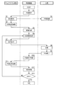
以下、本実施形態の作業管理システム1の動作について図5を用いて説明する。先ず、作業者W1が作業を開始すべく制御装置2を操作すると、制御装置2の処理部24は、作業内容のデータを含む指示信号をウェアラブル端末4に向けて送信する処理を実行する(S1)。なお、制御装置2の処理部24は、作業者W1による工具3及びウェアラブル端末4の何れかの操作をトリガとして‘S1’のフローを実行するように構成されていてもよい。   Hereinafter, the operation of the work management system 1 according to the present embodiment will be described with reference to FIG. First, when the worker W1 operates the control device 2 to start work, the processing unit 24 of the control device 2 executes processing for transmitting an instruction signal including data of work content to the wearable terminal 4 (S1) ). The processing unit 24 of the control device 2 may be configured to execute the flow of 'S1' triggered by the operation of either the tool 3 or the wearable terminal 4 by the worker W1.

ウェアラブル端末4の処理装置44は、指示信号を受信すると、指示信号に含まれる作業箇所を表す指示画像のデータ、及び作業に必要な指示データ(例えば、ねじ10の規格や規定の締付トルク)を表示装置42に投影(表示)させる処理を実行する(S2)。作業者W1は、表示装置42に投影された指示画像を見ることで、作業箇所を特定する。また、作業者W1は、指示データを見ることで、工具3を用いた作業に必要な準備を行う(S3)。例えば、工具3がインパクトドライバ310であれば、作業者W1は、ねじ10の規格に応じたビット314Aを出力軸314に取り付けたり、設定トルクを設定したりする。   When the processing device 44 of the wearable terminal 4 receives the instruction signal, the data of the instruction image representing the work location included in the instruction signal and the instruction data necessary for the operation (for example, the standard of the screw 10 or tightening torque specified) Is executed on the display unit 42 (S2). The worker W1 identifies the work location by looking at the instruction image projected on the display device 42. In addition, the worker W1 prepares for the work using the tool 3 by looking at the instruction data (S3). For example, if the tool 3 is the impact driver 310, the worker W1 attaches the bit 314A according to the standard of the screw 10 to the output shaft 314 or sets the set torque.

次に、作業者W1は、ウェアラブル端末4の撮像装置41を操作する。この操作により、処理装置44は、作業箇所及び作業箇所の周辺を撮像装置41に撮像させる撮像処理を実行する(S4)。このとき、作業者W1は、撮像の前に、作業箇所が視界の中央に位置するように、頭部を動かす等して撮像装置41の位置を調整するのが好ましい。また、表示装置42に撮像範囲の指標となる枠を表示する場合は、作業者W1は、当該枠内に作業箇所が収まるように、頭部を動かす等して撮像装置41の位置を調整する。そして、処理装置44は、撮像した撮像画像のデータを制御装置2に向けて送信する処理を実行する。   Next, the worker W 1 operates the imaging device 41 of the wearable terminal 4. By this operation, the processing device 44 executes an imaging process that causes the imaging device 41 to image the work location and the periphery of the work location (S4). At this time, it is preferable for the worker W1 to adjust the position of the imaging device 41 by moving the head or the like so that the work location is located at the center of the field of view before imaging. In addition, when displaying a frame that is an index of the imaging range on the display device 42, the worker W1 adjusts the position of the imaging device 41 by moving the head or the like so that the work part is contained in the frame. . Then, the processing device 44 executes processing for transmitting data of the captured image to the control device 2.

制御装置2の処理部24は、撮像画像のデータを受信すると、予め記憶してある作業箇所の指示画像と撮像画像とを比較し、作業者W1が正しい作業箇所で作業を行おうとしているか否かを確認する確認処理を実行する(S5)。この確認処理では、例えば撮像画像のデータと、指示画像のデータとを比較して類似度を求める。そして、この確認処理では、求めた類似度が予め設定されている閾値以上であれば正常(作業者W1が正しい作業箇所で作業を行おうとしている)と判定し、閾値未満であれば異常(作業者W1が誤った作業箇所で作業を行おうとしている)と判定する。正常と判定した場合、処理部24は、作業者W1に作業を開始するように指示する開始信号をウェアラブル端末4に向けて送信する処理を実行する(S6)。   When the data of the captured image is received, the processing unit 24 of the control device 2 compares the instruction image of the work location stored in advance with the captured image, and whether or not the worker W1 tries to work at the correct work location In step S5, a confirmation process is performed to confirm whether or not there is a problem. In this confirmation processing, for example, data of a captured image and data of an instruction image are compared to obtain a similarity. Then, in this confirmation processing, it is determined that the calculated similarity is equal to or greater than a preset threshold value as normal (the worker W1 is trying to work at the correct work location), and is less than the threshold value if abnormal It is determined that the worker W1 is trying to work at the wrong work point). If it is determined that the processing is normal, the processing unit 24 executes processing of transmitting a start signal instructing the worker W1 to start work toward the wearable terminal 4 (S6).

ここで、「類似度」は、撮像画像のデータと指示画像のデータとがどれだけ似ているかを数値化したパラメータであればよい。例えば、撮像画像と指示画像との差分画像を求め、差分画像において濃淡値が所定値よりも小さい画素数を類似度として求めてもよい。また、例えば、撮像画像と指示画像との差分画像を求め、更に差分画像を2値化して2値画像を求め、当該2値画像をラベリングし、ラベリングされた領域の面積を類似度として求めてもよい。   Here, the “degree of similarity” may be a parameter that numerically represents how similar the data of the captured image and the data of the instruction image are. For example, a difference image between the captured image and the instruction image may be obtained, and the number of pixels whose gray value is smaller than a predetermined value in the difference image may be obtained as the similarity. Further, for example, a difference image between the captured image and the instruction image is obtained, and the difference image is binarized to obtain a binary image, the binary image is labeled, and the area of the labeled region is obtained as the similarity. It is also good.

なお、異常と判定した場合は、処理部24は、作業者W1に作業箇所を再度撮像するように指示する信号をウェアラブル端末4に向けて送信する処理を実行する。そして、作業者W1が正しい作業箇所で作業を行おうとしていることを確認できるまで、上述の‘S1’,‘S2’,‘S4’,‘S5’のフローを繰り返す。   In addition, when it determines with it being abnormal, the process part 24 performs the process which transmits toward the wearable terminal 4 the signal which instruct | indicates that the worker W1 images a work location again. Then, the above-mentioned flow of 'S1', 'S2', 'S4' and 'S5' is repeated until it can be confirmed that the worker W1 is going to work at the correct work place.

ウェアラブル端末4の処理装置44は、開始信号を受信すると、作業者W1に作業の開始を促す画像やメッセージを表示装置42に投影させる処理を実行する(S7)。作業者W1は、表示装置42に投影された画像又はメッセージを見ることで、工具3を用いた作業を開始する(S8)。ここでは、作業者W1は、工具3を用いてねじ10をワーク11に締め付ける作業を行う。このとき、工具3の測定部31は、ねじ10を締め付ける際に、ねじ10に与えられる締付トルクを測定する。作業が終了すると、工具3の通信部32は、測定部31で測定された締付トルクのデータを制御装置2に向けて送信する処理を実行する(S9)。   When the processing device 44 of the wearable terminal 4 receives the start signal, the processing device 44 executes a process of causing the display device 42 to project an image or a message prompting the worker W1 to start the work (S7). The worker W1 starts work using the tool 3 by looking at the image or message projected on the display device 42 (S8). Here, the worker W 1 uses the tool 3 to fasten the screw 10 to the work 11. At this time, when the screw 10 is tightened, the measuring unit 31 of the tool 3 measures the tightening torque applied to the screw 10. When the operation is completed, the communication unit 32 of the tool 3 executes a process of transmitting data of the tightening torque measured by the measurement unit 31 to the control device 2 (S9).

締付トルクのデータを受信すると、制御装置2の処理部24は、作業者W1による作業が終了したと判定し、作業者W1に作業後の作業箇所を撮像するように指示する信号をウェアラブル端末4に向けて送信する処理を実行する(S10)。当該信号を受信すると、ウェアラブル端末4の処理装置44は、作業者W1に作業箇所を撮像するように促す画像やメッセージを表示装置42に投影させる処理を実行する。   When the data of the tightening torque is received, the processing unit 24 of the control device 2 determines that the work by the worker W1 is finished, and the wearable terminal instructs the worker W1 to image the working place after the work A process of transmitting to 4 is executed (S10). When the signal is received, the processing device 44 of the wearable terminal 4 executes a process of causing the display device 42 to project an image or a message prompting the worker W1 to image the work location.

作業者W1は、表示装置42に表示された画像又はメッセージを見ることで、撮像装置41を操作する。この操作により、処理装置44は、作業箇所及び作業箇所の周辺を撮像装置41に撮像させる撮像処理を実行する(S11)。このとき、作業者W1は、‘S4’のフローと同様に、撮像の前に頭部を動かす等して撮像装置41の位置を調整するのが好ましい。そして、処理装置44は、撮像した撮像画像のデータを制御装置2に向けて送信する処理を実行する。   The operator W1 operates the imaging device 41 by viewing an image or a message displayed on the display device 42. By this operation, the processing device 44 executes an imaging process that causes the imaging device 41 to image the work location and the periphery of the work location (S11). At this time, it is preferable for the worker W1 to adjust the position of the imaging device 41 by moving the head or the like before imaging, as in the flow of 'S4'. Then, the processing device 44 executes processing for transmitting data of the captured image to the control device 2.

なお、上述の‘S4’,‘S11’のフローでは、作業者W1が撮像装置41を操作することで作業箇所及び作業箇所の周辺を撮像しているが、撮像装置41が自動的に撮像する構成であってもよい。例えば、表示装置42に表示されている枠内に作業箇所が収まった時点で撮像装置41が自動的に撮像する構成であってもよい。   In the above-described flow of 'S4' and 'S11', the operator W1 picks up an image of the work area and the area around the work area by operating the image pickup apparatus 41, but the image pickup apparatus 41 automatically picks up an image It may be a configuration. For example, the configuration may be such that the imaging device 41 automatically picks up an image when the work place is contained within the frame displayed on the display device 42.

撮像画像のデータを受信すると、制御装置2の処理部24は、既に取得してある締付トルクと撮像画像のデータとに基づいて、作業が正常に行われたか否かを判定する判定処理を実行する(S12)。正常と判定した場合(S13:YES)、処理部24は、現在の作業箇所での作業が終了したと判定し、次の作業箇所に関する指示信号をウェアラブル端末4に向けて送信する処理を実行する。異常と判定した場合(S13:NO)、処理部24は、作業を正しく行うように指示する信号をウェアラブル端末4に向けて送信する処理を実行する。そして、作業者W1が作業を正常に行ったと判定するまで、上述の‘S6’〜‘S13’のフローを繰り返す。そして、全ての作業箇所について作業が終了するまで、上記の‘S1’〜‘S13’のフローを繰り返す。   When the data of the captured image is received, the processing unit 24 of the control device 2 performs a determination process of determining whether the work has been normally performed based on the already acquired tightening torque and the data of the captured image. Execute (S12). When it determines with normal (S13: YES), processing part 24 determines with work by the present work place having been completed, and performs processing which transmits an indication signal about the next work place to wearable terminal 4 . When it determines with it being abnormal (S13: NO), the process part 24 performs the process which transmits the signal which instruct | indicates that work is correctly performed toward the wearable terminal 4 to it. Then, the above-described flow of 'S6' to 'S13' is repeated until it is determined that the worker W1 has normally performed the work. Then, the above-mentioned flow of 'S1' to 'S13' is repeated until the work is completed for all the work parts.

なお、ここでは、‘S13’のフローにおいて異常と判定した場合、制御装置2の処理部24は、同じ作業を再度行うように作業者W1に指示しているが、この指示を行うか否かは任意である。また、制御装置2の処理部24は、全ての作業箇所について作業を終えた後に、異常と判定された作業の各々について、同じ作業を再度行うように作業者W1に指示するように構成されていてもよい。   Here, when it is determined that the process is abnormal in the flow of 'S13', the processing unit 24 of the control device 2 instructs the worker W1 to perform the same operation again, but whether or not to perform this instruction Is optional. In addition, the processing unit 24 of the control device 2 is configured to instruct the worker W1 to perform the same work again for each of the works determined to be abnormal after finishing the work for all the work parts. May be

以下、‘S12’のフローにおける判定処理について詳細に説明する。先ず、制御装置2の処理部24は、工具3から送信された締付トルクと目標トルクとを比較する処理を実行する。例えば、表1の番号‘1’に対応する作業であれば、工具3で測定された締付トルクが19.8(N・m)であり、目標トルクである20±10%(N・m)の範囲に収まっている。したがって、この場合、処理部24は、ねじ10が十分に締め付けられていると判定する。なお、締付トルクが目標トルクの範囲内に収まっていない場合は、処理部24は、異常(作業が正常に行われていない)と判定する。   Hereinafter, the determination process in the flow of 'S12' will be described in detail. First, the processing unit 24 of the control device 2 executes a process of comparing the tightening torque transmitted from the tool 3 with the target torque. For example, in the case of work corresponding to the number '1' in Table 1, the tightening torque measured by the tool 3 is 19.8 (N · m), and the target torque is 20 ± 10% (N · m) It is in the range of). Therefore, in this case, the processing unit 24 determines that the screw 10 is sufficiently tightened. When the tightening torque is not within the range of the target torque, the processing unit 24 determines that the operation is abnormal (the operation is not normally performed).

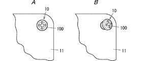
ここで、締結部品(ここでは、ねじ10)が十分に締め付けられている場合でも、作業が正常に行われているとは限らない。例えば、図6Aに示すように、ワーク11(作業箇所)を施工面に直交する方向(同図における紙面に直交する方向)から見て、ねじ10が傾いていない場合、ねじ10は正しく締め付けられている(つまり、作業が正常に行われている)。一方、図6Bに示すように、ワーク11を施工面に直交する方向から見て、ねじ10が傾いている場合、ねじ10は正しく締め付けられていない(つまり、作業が正常に行われていない)。なお、「直交」は、厳密な意味で「直交」でなくてもよい。   Here, even when the fastening part (here, the screw 10) is sufficiently tightened, the work is not always performed normally. For example, as shown in FIG. 6A, when the screw 10 is not inclined when the work 11 (working point) is viewed from the direction orthogonal to the work surface (direction orthogonal to the page in FIG. 6A), the screw 10 is correctly tightened. (That is, the work is done normally). On the other hand, as shown in FIG. 6B, when the screw 10 is inclined when the work 11 is viewed from the direction perpendicular to the work surface, the screw 10 is not properly tightened (that is, the work is not properly performed) . Note that “orthogonal” may not be “orthogonal” in a strict sense.

そこで、締結部品が十分に締め付けられていると判定した場合、次に処理部24は、撮像画像のデータと目標画像のデータとを比較する処理を実行する。この処理では、例えば‘S5’のフローと同様に、撮像画像のデータと、目標画像のデータとを比較して類似度を求める。そして、この処理では、求めた類似度が予め設定されている閾値以上であれば正常(作業が正常に行われている)と判定し、閾値未満であれば異常(作業が正常に行われていない)と判定する。例えば、表1の番号‘1’に対応する作業であれば、処理部24は、目標画像のデータB(1)と撮像画像のデータC(1)とを比較して求めた類似度が閾値以上であれば、正常(ねじ10がワーク11に正しく締め付けられている)と判定する。一方、処理部24は、求めた類似度が閾値未満であれば、異常(ねじ10がワーク11に対して正しく締め付けられていない)と判定する。   Therefore, when it is determined that the fastening component is sufficiently tightened, the processing unit 24 next executes a process of comparing data of the captured image with data of the target image. In this process, for example, similarly to the flow of 'S5', the data of the captured image and the data of the target image are compared to obtain the similarity. Then, in this process, if the calculated similarity is equal to or greater than a preset threshold, it is determined as normal (the work is normally performed), and if less than the threshold, it is abnormal (the work is normally performed). Not). For example, in the case of work corresponding to the number “1” in Table 1, the processing unit 24 compares the data B (1) of the target image with the data C (1) of the captured image as a threshold value. If it is above, it will be judged as normal (screw 10 is correctly tightened to work 11). On the other hand, if the calculated similarity is less than the threshold value, the processing unit 24 determines that it is abnormal (the screw 10 is not properly tightened on the work 11).

なお、判定処理において、処理部24は、撮像画像のデータと目標画像のデータとを比較することで、ねじ10の頭部100の径が規格(例えば、‘M8’や‘M10’等)と一致しているか否かを判定してもよい。例えば、‘M10’の規格のねじを締め付けなければならない作業箇所で、誤って‘M8’の規格のねじを締め付けた場合、処理部24は、異常と判定する。この場合、処理部24は、作業箇所に応じた適切な規格のねじ10を締め付けているか否かを判定することができる。   In the determination process, the processing unit 24 compares the data of the captured image with the data of the target image, so that the diameter of the head 100 of the screw 10 is a standard (for example, 'M8', 'M10', etc.) It may be determined whether or not they match. For example, if the screw of the 'M8' standard is mistakenly tightened at a work point where the 'M10' standard screw has to be tightened, the processing unit 24 determines that there is an abnormality. In this case, the processing unit 24 can determine whether or not the screw 10 of an appropriate standard according to the work place is tightened.

また、判定処理において、締付トルクが目標トルクを大幅に上回る等、異常な値を示す場合に、処理部24は、工具3の測定部31に異常があると判定してもよい。この場合、工具3の測定部31に異常がある旨を工具3又はウェアラブル端末4を通じて作業者W1に通知することで、工具3の修理や交換を促すことができる。その他、判定処理において、処理部24は、作業を開始してから終了するまでの間(作業期間)、締付トルクを定期的に工具3から取得し、その時系列のデータに基づいて締め付けが正常に行われているか否かを判定してもよい。例えば、作業期間中、締付トルクがほぼ一定であれば、処理部24は、正常に締め付けられていると判定することができる。一方、作業期間中、締付トルクが不連続に変化すれば、処理部24は、正常に締め付けられていないと判定することができる。   In addition, in the determination processing, when the tightening torque indicates an abnormal value such as exceeding the target torque significantly, the processing unit 24 may determine that the measuring unit 31 of the tool 3 has an abnormality. In this case, by notifying the operator W1 that there is an abnormality in the measurement unit 31 of the tool 3 through the tool 3 or the wearable terminal 4, repair or replacement of the tool 3 can be promoted. In addition, in the determination process, the processing unit 24 periodically acquires the tightening torque from the tool 3 during the period from the start to the end of the operation (operation period), and the tightening is normal based on the time-series data It may be determined whether or not it is performed. For example, if the tightening torque is substantially constant during the operation period, the processing unit 24 can determine that the tightening is normally performed. On the other hand, if the tightening torque changes discontinuously during the operation period, the processing unit 24 can determine that the tightening is not properly performed.

上述のように、本実施形態の制御装置2及び作業管理システム1では、工具3により締結部品に与えられる締付トルクと、撮像装置41により撮像された作業箇所の撮像画像とに基づいて、作業者W1による作業が正常に行われているか否かを判定する。したがって、本実施形態の制御装置2及び作業管理システム1は、締結部品が正しく締め付けられているか否かの状態(すなわち、工具3を用いた作業の状態)を把握することができる。このため、本実施形態の制御装置2及び作業管理システム1では、作業の状態に応じて適切な指示を作業者W1に与えることで、作業効率を向上することができる。更に、本実施形態の制御装置2及び作業管理システム1では、作業の状態を把握することにより、作業者W1によるミスを低減することができるので、作業による作製される製品の品質の向上を図ることができるという利点もある。   As described above, in the control device 2 and the work management system 1 according to the present embodiment, the work is performed based on the tightening torque given to the fastening part by the tool 3 and the captured image of the work location captured by the imaging device 41 It is determined whether the work by the person W1 is normally performed. Therefore, the control device 2 and the work management system 1 of the present embodiment can grasp the state (i.e., the state of the work using the tool 3) whether or not the fastening part is properly tightened. For this reason, in the control device 2 and the work management system 1 of the present embodiment, the work efficiency can be improved by giving the worker W1 an appropriate instruction according to the state of the work. Furthermore, in the control device 2 and the work management system 1 according to the present embodiment, it is possible to reduce mistakes made by the worker W1 by grasping the state of the work, so the quality of the product produced by the work is improved. It also has the advantage of being able to

特に、本実施形態の制御装置2では、処理部24は、判定処理において、作業箇所において締結部品が正常に締め付けられた状態を示す目標画像と撮像画像とを比較して類似度を求めている。且つ、処理部24は、作業で要求される目標トルクと締付トルクとの比較結果と、類似度と予め設定されている閾値との比較結果とに基づいて、作業が正常に行われているか否かを判定している。この構成では、締結部品が正しく締め付けられているか否かの状態をより的確に把握することができる。なお、当該構成を採用するか否かは任意である。   In particular, in the control device 2 of the present embodiment, the processing unit 24 determines the similarity by comparing the target image showing the state in which the fastening component is normally tightened at the work location with the captured image in the determination process. . In addition, whether the processing unit 24 normally performs the work based on the comparison result of the target torque and the tightening torque required in the work and the comparison result of the similarity degree and the threshold set in advance. It is judged whether or not. In this configuration, the state of whether or not the fastening part is properly tightened can be grasped more accurately. In addition, it is arbitrary whether to employ | adopt the said structure.

また、本実施形態の制御装置2では、締付トルクのデータを受信すると、処理部24は、作業者W1による作業が終了したと判定し、作業者W1に作業後の作業箇所を撮像するように指示する信号をウェアラブル端末4に向けて送信する処理を実行してもよい。そして、ウェアラブル端末4の撮像装置41は、当該信号を受信すると、作業箇所を自動的に撮像してもよい。つまり、本実施形態の制御装置2では、工具3からの信号をトリガとして撮像装置41による撮像のタイミングを決定してもよい。この構成では、作業者W1が工具3を用いて作業を終える際に撮像装置41による撮像が行われるので、作業者W1の手を煩わせずに作業箇所を撮像できるという利点がある。なお、当該構成を採用するか否かは任意である。   Further, in the control device 2 of the present embodiment, when the data of the tightening torque is received, the processing unit 24 determines that the work by the worker W1 is finished, and picks up the work part after the work to the worker W1. A process of transmitting a signal instructing to the wearable terminal 4 may be executed. Then, when the imaging device 41 of the wearable terminal 4 receives the signal, the imaging device 41 may automatically image the work location. That is, in the control device 2 of the present embodiment, the timing of imaging by the imaging device 41 may be determined using a signal from the tool 3 as a trigger. In this configuration, when the worker W1 uses the tool 3 to finish the work, the imaging device 41 performs imaging, so that there is an advantage that the operator W1 can be imaged without bothering the hand of the worker W1. In addition, it is arbitrary whether to employ | adopt the said structure.

また、本実施形態の制御装置2は、作業者W1に対する作業の指示内容を、文字及び画像の少なくとも一方を用いて表示する表示部21を備えている。この構成では、作業者W1に指示内容を視覚により伝えることができる。なお、当該構成を採用するか否かは任意である。   In addition, the control device 2 of the present embodiment includes the display unit 21 that displays the instruction content of the work for the worker W1 using at least one of a character and an image. In this configuration, it is possible to visually convey the instruction content to the worker W1. In addition, it is arbitrary whether to employ | adopt the said structure.

また、本実施形態の制御装置2では、撮像画像は、作業箇所を施工面に直交する方向から見た画像である。このため、本実施形態の制御装置2は、締結部品が施工面に直交する方向に締め付けられているか否かを判定することができるので、締結部品が施工面に正しく締め付けられているか否かを容易に判定することができる。なお、当該構成を採用するか否かは任意である。   Moreover, in the control apparatus 2 of this embodiment, a captured image is an image which looked at the work location from the direction orthogonal to a construction surface. For this reason, since the control device 2 of the present embodiment can determine whether or not the fastening component is tightened in the direction orthogonal to the work surface, it is determined whether or not the fastening component is properly tightened on the work surface It can be easily determined. In addition, it is arbitrary whether to employ | adopt the said structure.

また、本実施形態の作業管理システム1では、ウェアラブル端末4は、制御装置2から送信される作業者W1に対する作業の指示内容を文字及び画像の少なくとも一方を用いて表示する表示装置42を備えている。このため、本実施形態の作業管理システム1では、作業者W1は、身に着けている表示装置42に目を移すだけで、作業の指示内容を容易に確認することができる。なお、当該構成を採用するか否かは任意である。   Further, in the work management system 1 of the present embodiment, the wearable terminal 4 includes the display device 42 that displays the contents of the work instruction to the worker W1 transmitted from the control device 2 using at least one of characters and images. There is. For this reason, in the work management system 1 of the present embodiment, the worker W1 can easily confirm the contents of the work instruction simply by looking at the display device 42 worn. In addition, it is arbitrary whether to employ | adopt the said structure.

また、本実施形態の作業管理システム1では、工具3は、ヘッド301と、ロードセル(検出部)305と、CPU(トルク演算部)306とを備えるトルクレンチ300であるのが好ましい。この構成では、工具3が実際に締結部品に与えたトルクを測定して締付トルクを得ることができるので、作業が正常に行われたか否かの判定を精度良く行うことができる。なお、工具3を上記のトルクレンチ300とするか否かは任意である。   Further, in the work management system 1 according to the present embodiment, the tool 3 is preferably a torque wrench 300 including a head 301, a load cell (detection unit) 305, and a CPU (torque calculation unit) 306. In this configuration, since it is possible to obtain the tightening torque by measuring the torque actually applied to the fastening part by the tool 3, it is possible to accurately determine whether the work has been performed normally. Note that it is optional whether or not the tool 3 is the torque wrench 300 described above.

また、工具3は、インパクト機構311と、出力軸314と、磁歪式のトルクセンサ316(第1検出部)と、加速度センサ315(第2検出部)と、制御回路317(トルク演算部)とを備えるインパクトドライバ310であってもよい。この構成でも、工具3が実際に締結部品に与えたトルクを測定して締付トルクを得ることができるので、作業が正常に行われたか否かの判定を精度良く行うことができる。なお、工具3を上記のインパクトドライバ310とするか否かは任意である。   Further, the tool 3 includes an impact mechanism 311, an output shaft 314, a magnetostrictive torque sensor 316 (first detection unit), an acceleration sensor 315 (second detection unit), and a control circuit 317 (torque calculation unit). The impact driver 310 may be provided with In this configuration as well, the torque that the tool 3 actually gives to the fastening component can be measured to obtain the tightening torque, so it can be accurately determined whether the work has been performed normally. Note that whether or not the tool 3 is the impact driver 310 described above is optional.

また、本実施形態の作業管理システム1では、ウェアラブル端末4は、例えば防護用メガネやゴーグル、ヘルメットといった作業者W1の頭部に装着する機器である。この構成では、作業者W1の視界が撮像装置41の撮像範囲と殆ど同じになるため、作業箇所を撮像し易いという利点がある。更に、この構成では、作業者W1が意識せずとも作業者W1の視界にある表示装置42に作業の指示内容などの情報が映し出されるため、作業者W1が作業し易く、また、作業者W1が作業の指示内容を見落としがたいという利点もある。なお、当該構成を採用するか否かは任意である。   Further, in the work management system 1 of the present embodiment, the wearable terminal 4 is a device mounted on the head of the worker W1, for example, protective glasses, goggles, and a helmet. In this configuration, since the field of view of the worker W1 is almost the same as the imaging range of the imaging device 41, there is an advantage that the work location can be easily imaged. Furthermore, in this configuration, since information such as the instruction content of the work is displayed on the display device 42 in the field of view of the worker W1 even if the worker W1 is not aware of it, the worker W1 can easily work and the worker W1 There is also the advantage that it is difficult to overlook the contents of work instructions. In addition, it is arbitrary whether to employ | adopt the said structure.

また、本実施形態の作業管理システム1では、ウェアラブル端末4及び制御装置2の少なくとも一方は、作業者W1に対する作業の指示内容を音声で出力する機能を備えるのが好ましい。この構成では、聴覚を利用して作業の指示内容を作業者W1に伝えることができるので、作業者W1が作業を中断する必要が無く、作業し易いという利点がある。なお、当該構成を採用するか否かは任意である。   Further, in the work management system 1 according to the present embodiment, it is preferable that at least one of the wearable terminal 4 and the control device 2 has a function of outputting the contents of the work instruction to the worker W1 by voice. In this configuration, since the instruction content of the work can be transmitted to the worker W1 using the hearing, there is an advantage that the worker W1 does not have to interrupt the work and it is easy to work. In addition, it is arbitrary whether to employ | adopt the said structure.

また、本実施形態の作業管理システム1では、上位装置5を備えている。そして、上位装置5は、制御装置2から送信される締付トルクのデータ及び撮像画像のデータを作業毎に記憶している。この構成では、上位装置5を用いて作業者W1により行われた作業の履歴を管理することができるので、作業管理と品質管理とを併せて容易に行うことができるという利点がある。   Further, the work management system 1 according to the present embodiment is provided with the host device 5. The host device 5 stores the data of the tightening torque and the data of the captured image transmitted from the control device 2 for each operation. In this configuration, since the history of the work performed by the worker W1 can be managed using the higher-level device 5, there is an advantage that the work management and the quality management can be easily performed together.

更に、本実施形態の作業管理システム1では、上位装置5は、制御装置2に電気的に接続される機器(例えば、工具3やウェアラブル端末4)の情報を記憶するのが好ましい。機器の情報としては、例えば機器の各種パラメータの校正情報や、機器の位置情報、機器を取り扱う作業者W1の情報、機器を用いて作業を行った時刻情報などが挙げられる。この構成では、作業毎の締付トルクの管理だけではなく、制御装置2に接続される機器や、当該機器を取り扱う作業者W1についても管理することができ、よりきめ細やかな作業管理を行うことが可能である。例えば、この構成では、機器を取り扱う作業者W1の作業精度や、作業時間の履歴を参照することで、より精度の良い作業が行われるように作業計画を変更することが可能である。また、この構成では、作業精度の低い作業者W1に対して、作業マニュアルを閲覧させる等の個別指導を行うことも可能である。   Furthermore, in the work management system 1 of the present embodiment, the higher-level device 5 preferably stores information of an apparatus (for example, the tool 3 or the wearable terminal 4) electrically connected to the control device 2. The information of the device includes, for example, calibration information of various parameters of the device, position information of the device, information of the worker W1 who handles the device, time information when the work is performed using the device, and the like. In this configuration, not only the management of the tightening torque for each operation but also the equipment connected to the control device 2 and the worker W1 who handles the equipment can be managed, and more detailed work management is performed. Is possible. For example, in this configuration, it is possible to change the work plan so that more accurate work is performed by referring to the work accuracy of the worker W1 who handles the equipment and the history of the work time. Further, in this configuration, it is possible to give individual guidance such as viewing the work manual for the worker W1 with low work accuracy.

なお、本実施形態の作業管理システム1が上位装置5を備えるか否かは任意である。本実施形態の作業管理システム1が上位装置5を備えない場合は、制御装置2の記憶部22に、締付トルクのデータ及び撮像画像のデータや機器の情報を作業毎に記憶させればよい。このように構成すれば、制御装置2に上位装置5と同様の機能を持たせることができる。   In addition, it is arbitrary whether the work management system 1 of this embodiment is provided with the high-order apparatus 5 or not. If the work management system 1 according to the present embodiment does not include the higher-level device 5, data of tightening torque, data of a captured image, and information of equipment may be stored in the storage unit 22 of the control device 2 for each work. . With this configuration, the control device 2 can have the same function as that of the upper device 5.

ところで、本実施形態の作業管理システム1は、図7A,図7Bに示すような部品管理システム6と連携することも可能である。部品管理システム6は、所定の生産計画に従って、複数の部品箱71から順番に部品P1を取り出し、取り出した部品P1を組み立てる所謂セル生産方式で用いられるシステムである。この部品管理システム6は、図7A,図7Bに示すように、複数の部品箱71で構成される部品棚7と、複数の部品箱71に1対1で取り付けられる複数の表示器8と、作業者W1が作業を行う作業台9とを備えている。複数の部品箱71には、それぞれ部品P1が配置されている。部品P1は、部品箱71毎に異なる種類であってもよく、また、幾つかの部品箱71において、同じ種類の部品P1が配置されていてもよい。この部品管理システム6では、本実施形態の制御装置2が複数の表示器8を制御している。   By the way, the work management system 1 of the present embodiment can also cooperate with the parts management system 6 as shown in FIGS. 7A and 7B. The parts management system 6 is a system used in a so-called cell production system in which the parts P1 are taken out sequentially from the plurality of parts boxes 71 according to a predetermined production plan, and the taken out parts P1 are assembled. The parts management system 6 includes, as shown in FIGS. 7A and 7B, a component shelf 7 configured of a plurality of component boxes 71, and a plurality of indicators 8 attached to the plurality of component boxes 71 on a one-to-one basis. It has a workbench 9 on which a worker W1 works. Parts P1 are arranged in the plurality of parts boxes 71, respectively. The parts P1 may be of different types for each part box 71, and in some part boxes 71, parts P1 of the same kind may be arranged. In the parts management system 6, the control device 2 of the present embodiment controls a plurality of displays 8.

表示器8は、ケーブル(図示せず)により制御装置2に電気的に接続されている。表示器8は、制御装置2から送信される信号に応じて点灯するように構成されている。制御装置2は、所定の生産計画に応じて複数の表示器8の何れかを点灯させることにより、当該表示器8に対応する部品箱71から部品P1を取り出すように作業者W1を促すように構成されている。また、表示器8は、作業者W1が操作可能なスイッチ(またはレバー)81を備えている。表示器8が点灯している状態において、このスイッチ81を作業者W1が操作することで、表示器8が消灯する。   The display 8 is electrically connected to the control device 2 by a cable (not shown). The display 8 is configured to light up in response to a signal transmitted from the control device 2. The control device 2 urges the worker W1 to take out the part P1 from the part box 71 corresponding to the display 8 by lighting any one of the plurality of displays 8 according to the predetermined production plan. It is configured. The display 8 also includes a switch (or lever) 81 operable by the worker W1. When the operator W1 operates the switch 81 while the display 8 is on, the display 8 is turned off.

以下、部品管理システム6における制御装置2の動作について説明する。制御装置2の処理部24は、スイッチ81の操作により表示器8から出力される信号に基づいて、当該表示器8に対応する部品箱71から部品P1が取り出されたと判定する。また、処理部24は、部品P1が取り出されたと判定すると、作業者W1に取り出した部品P1を撮像するように指示する信号をウェアラブル端末4に向けて送信する処理を実行する。ウェアラブル端末4の処理装置44は、当該信号を受信すると、作業者W1に取り出した部品P1を撮像するように促す画像やメッセージを表示装置42に投影させる処理を実行する。   Hereinafter, the operation of the control device 2 in the component management system 6 will be described. The processing unit 24 of the control device 2 determines that the component P1 has been taken out from the component box 71 corresponding to the display 8 based on the signal output from the display 8 by the operation of the switch 81. In addition, when determining that the part P1 has been taken out, the processing unit 24 executes processing for transmitting a signal instructing the worker W1 to pick up the taken part P1 to the wearable terminal 4. When the processing device 44 of the wearable terminal 4 receives the signal, the processing device 44 executes a process of causing the display device 42 to project an image or a message prompting the worker W1 to pick up the component P1 taken out.

作業者W1は、表示装置42に表示された画像又はメッセージを見ることで、撮像装置41を操作する。この操作により、処理装置44は、取り出した部品P1を撮像装置41に撮像させる撮像処理を実行する。なお、処理装置44は、制御装置2からの信号を受信すると撮像装置41に自動的に撮像させる処理を実行してもよい。そして、処理装置44は、撮像した撮像画像のデータを制御装置2に向けて送信する処理を実行する。   The operator W1 operates the imaging device 41 by viewing an image or a message displayed on the display device 42. By this operation, the processing device 44 executes an imaging process that causes the imaging device 41 to image the taken out component P1. Note that the processing device 44 may execute processing for causing the imaging device 41 to automatically take an image when receiving a signal from the control device 2. Then, the processing device 44 executes processing for transmitting data of the captured image to the control device 2.

制御装置2の処理部24は、撮像画像のデータを受信すると、予め記憶してある部品P1の画像と撮像画像とを比較し、作業者W1が正しい部品を取り出したか否かを確認する処理を実行する。言い換えれば、処理部24は、取り出した部品P1を撮像装置41で撮像した画像と、予め記憶してある部品P1の画像とを比較することで、正しい部品P1が複数の部品箱71の何れかから取り出されているか否かを判定する処理を実行する。この処理では、例えば撮像画像のデータと、部品P1の画像のデータとを比較して類似度を求める。そして、この処理では、求めた類似度が予め設定されている閾値以上であれば正常(作業者W1が正しい部品P1を取り出した)と判定し、閾値未満であれば異常(作業者W1が誤った部品P1を取り出した)と判定する。   When the data of the captured image is received, the processing unit 24 of the control device 2 compares the image of the component P1 stored in advance with the captured image to confirm whether the worker W1 has taken out the correct component or not. Run. In other words, the processing unit 24 compares the image of the taken out component P1 with the imaging device 41 with the image of the component P1 stored in advance, so that the correct component P1 is any of the plurality of component boxes 71. Execute processing to determine whether or not it has been taken out of. In this process, for example, the data of the captured image and the data of the image of the part P1 are compared to obtain the similarity. Then, in this process, if the calculated similarity is equal to or more than a preset threshold value, it is judged as normal (the worker W1 takes out the correct part P1), and if it is less than the threshold, it is abnormal It is determined that the part P1 has been taken out).

正常と判定した場合、処理部24は、次に取り出すべき部品P1が収納されている部品箱71に対応した表示器8を点灯させる処理を実行する。異常と判定した場合、処理部24は、例えば正しい部品P1が収納されている部品箱71に対応する表示器8を点滅させる処理や、正しい部品P1を取り出すように指示する信号をウェアラブル端末4に向けて送信する処理を実行する。   If it is determined that the operation is normal, the processing unit 24 executes a process of lighting the display 8 corresponding to the component box 71 in which the component P1 to be taken out next is stored. If it is determined that there is an abnormality, the processing unit 24 instructs the wearable terminal 4 to blink the display 8 corresponding to the component box 71 in which the correct component P1 is stored, for example, and to instruct the wearable terminal 4 to take out the correct component P1. Execute processing to direct and send.

この構成では、制御装置2は、取り出した部品P1を組み立てる作業(ここでは、締結部品を締め付ける作業)と、その前段階である部品P1を取り出す作業とを一括して管理することができるという利点がある。更に、この構成では、上記の判定処理により作業者W1が誤った部品P1を取り出したと判定すれば、制御装置2から作業者W1に通知することで、正しい部品P1を取り出すように作業者W1に促すことが可能となる。   In this configuration, the control device 2 can collectively manage the work of assembling the taken out part P1 (here, the work of tightening the fastening part) and the work of taking out the part P1 in the previous stage. There is. Furthermore, in this configuration, if it is determined by the above determination processing that the worker W1 has taken out the wrong part P1, the control device 2 notifies the worker W1 to take out the correct part P1 to the worker W1. It is possible to prompt.

なお、本実施形態の制御装置2及び作業管理システム1では、締結部品を締め付ける作業について判定処理を実行しているが、他の作業について判定処理を実行してもよい。例えば、ワーク11に穴をあける作業であれば、工具3は、穴をあける際にワーク11に与えるトルクのデータを制御装置2に向けて送信する。また、撮像装置41は、作業後の穴のあいた作業箇所を撮像する。そして、制御装置2の処理部24は、工具3から送信されるトルクが目標トルクを超えていれば、ワーク11に十分な大きさの穴があけられていると判定する処理を実行する。また、処理部24は、目標画像のデータと撮像画像のデータとを比較して類似度を求め、類似度と予め設定されている閾値とを比較することで、ワーク11に正しく穴があけられているか否かを判定する処理を実行する。   In addition, in the control apparatus 2 and the work management system 1 of this embodiment, although the determination process is performed about the operation | work which clamps a fastening component, you may perform the determination process about another operation | work. For example, in the case of a work to make a hole in the work 11, the tool 3 sends data of the torque to be given to the work 11 at the time of making a hole to the control device 2. In addition, the imaging device 41 captures an image of a work location with a hole after work. Then, when the torque transmitted from the tool 3 exceeds the target torque, the processing unit 24 of the control device 2 executes a process of determining that the workpiece 11 has a hole of a sufficient size. In addition, the processing unit 24 compares the data of the target image and the data of the captured image to obtain the degree of similarity, and compares the degree of similarity with the threshold set in advance, whereby a hole is correctly made in the work 11 Execute processing to determine whether or not

また、本実施形態の作業管理システム1では、ウェアラブル端末4に撮像装置41を設けているが、撮像装置41は、例えば工具3に設けていてもよい。この場合、工具3は、制御装置2から送信される指示信号に基づいて撮像装置41に作業箇所を撮像させる処理と、撮像装置41で撮像した撮像画像のデータを制御装置2に向けて送信する処理とを実行する機能を有していればよい。   Moreover, although the imaging device 41 is provided in the wearable terminal 4 in the operation | work management system 1 of this embodiment, the imaging device 41 may be provided in the tool 3, for example. In this case, the tool 3 causes the imaging device 41 to image the work location based on the instruction signal transmitted from the control device 2 and transmits the data of the imaged image captured by the imaging device 41 to the control device 2 It suffices to have a function to execute processing.

また、本実施形態の作業管理システム1では、制御装置2と上位装置5との間は、Bluetooth(登録商標)を用いた無線通信を行っているが、例えば、WiFi(登録商標)やZigBee(登録商標)等の無線規格を用いた無線通信を行ってもよい。また、制御装置2と上位装置5との間の無線通信には、LTE(Long Term Evolution)などの携帯電話の通信規格を用いてもよい。携帯電話の通信規格を用いて無線通信を行う場合は、例えば制御装置2が屋外に設置されており、作業者W1が屋外で作業を行う場合に特に有効である。   Further, in the work management system 1 of the present embodiment, wireless communication using Bluetooth (registered trademark) is performed between the control device 2 and the upper level device 5, but for example, WiFi (registered trademark) or ZigBee ( Wireless communication using a wireless standard such as a registered trademark may be performed. Further, for wireless communication between the control device 2 and the higher-level device 5, a communication standard of a mobile phone such as LTE (Long Term Evolution) may be used. When wireless communication is performed using the communication standard of the mobile phone, for example, the control device 2 is installed outdoors, which is particularly effective when the worker W1 works outdoors.

特に、携帯電話の通信規格を用いて無線通信を行う場合は、GPS(Global Positioning System)を用いた位置特定サービスや気象予報などの、携帯電話の回線を利用した既存のサービスを用いることができ、好ましい。つまり、この場合には、GPSにより制御装置2の位置を特定することができるので、上位装置5は、制御装置2や作業者W1の位置を管理することが可能となる。また、この場合には、気象予報により制御装置2が位置する場所での環境(例えば、高温多湿の気候など)を把握することができる。このため、上位装置5は、制御装置2の使用環境に応じた機器(工具3やウェアラブル端末4を含む)の寿命を推定して管理することが可能となる。   In particular, when performing wireless communication using a mobile phone communication standard, it is possible to use an existing service using a mobile phone line such as a location specifying service using a GPS (Global Positioning System) or a weather forecast. ,preferable. That is, in this case, since the position of the control device 2 can be specified by the GPS, the host device 5 can manage the positions of the control device 2 and the worker W1. Also, in this case, it is possible to grasp the environment (for example, the hot and humid climate etc.) at the place where the control device 2 is located by the weather forecast. Therefore, the host device 5 can estimate and manage the life of the device (including the tool 3 and the wearable terminal 4) according to the use environment of the control device 2.

また、本実施形態の作業管理システム1では、工具3は、インパクトドライバ310のように、充電池(二次電池)321を用いた電池駆動式であってもよい。この構成では、工具3と電源との間、又は工具3と圧縮空気源(エアコンプレッサ)との間を繋ぐケーブルが不要となるため、作業者W1がケーブルを気にせずに工具3を容易に取り扱うことができるという利点がある。   Further, in the work management system 1 of the present embodiment, the tool 3 may be a battery drive type using a rechargeable battery (secondary battery) 321 like the impact driver 310. In this configuration, the cable connecting the tool 3 and the power source or the tool 3 and the compressed air source (air compressor) is not required, so the worker W1 can easily make the tool 3 without worrying about the cable. It has the advantage of being able to be handled.

また、本実施形態の作業管理システム1では、制御装置2は、1つの工具3及び1つのウェアラブル端末4を制御するように構成されているが、他の構成であってもよい。例えば、制御装置2は、工具3及びウェアラブル端末4を1組として、複数の組の各々を制御するように構成されていてもよい。また、本実施形態の作業管理システム1では、上位装置5は、1つの制御装置2との間で通信を行っているが、複数の制御装置2の各々との間で通信を行うように構成されていてもよい。   Moreover, although the control apparatus 2 is comprised so that the one tool 3 and the one wearable terminal 4 may be controlled in the work management system 1 of this embodiment, you may be another structure. For example, the control device 2 may be configured to control each of a plurality of sets, with the tool 3 and the wearable terminal 4 as one set. Further, in the work management system 1 of the present embodiment, although the higher-level device 5 communicates with one control device 2, the higher-level device 5 is configured to communicate with each of a plurality of control devices 2. It may be done.

1 作業管理システム
10 ねじ(締結部品)
2 制御装置
23 通信部
24 処理部
3 工具
32 通信部
300 トルクレンチ
301 ヘッド
302A ソケット
305 ロードセル(検出部)
306 CPU(トルク演算部)
310 インパクトドライバ
311 インパクト機構
314 出力軸
314A ビット
316 トルクセンサ(第1検出部)
315 加速度センサ(第2検出部)
317 制御回路(トルク演算部)
4 ウェアラブル端末
41 撮像装置
42 表示装置
43 通信装置
5 上位装置
6 部品管理システム
71 部品箱
8 表示器
P1 部品
W1 作業者
1 Work management system 10 Screws (fastening parts)
Reference Signs List 2 control device 23 communication unit 24 processing unit 3 tool 32 communication unit 300 torque wrench 301 head 302A socket 305 load cell (detection unit)
306 CPU (torque calculation unit)
310 impact driver 311 impact mechanism 314 output shaft 314A bit 316 torque sensor (first detection unit)
315 Acceleration sensor (second detector)
317 Control circuit (torque calculation unit)
DESCRIPTION OF SYMBOLS 4 wearable terminal 41 imaging device 42 display device 43 communication device 5 host device 6 parts management system 71 parts box 8 indicator P1 parts W1 worker

Claims (10)

締結部品を締め付ける作業の際に用いられる工具との間、及び前記作業が行われる作業箇所を撮像する撮像装置との間でそれぞれ通信を行う通信部と、
前記工具により前記締結部品に与えられる締付トルクと、前記撮像装置により撮像された撮像画像とに基づいて、前記締結部品が正しく締め付けられているか否かを判定する判定処理を実行する処理部とを備え、
前記処理部は、前記判定処理において、前記作業で要求される目標トルクと前記締付トルクとの比較結果と、前記作業箇所において前記締結部品が正常に締め付けられた状態を示す目標画像と前記撮像画像との比較結果とに基づいて、前記締結部品が正しく締め付けられているか否かを判定することを特徴とする制御装置。
A communication unit for performing communication between a tool used in the operation of tightening the fastening part and an imaging device for imaging the work place where the operation is performed;
A processing unit that executes a determination process of determining whether or not the fastening component is properly tightened based on a tightening torque applied to the fastening component by the tool and a captured image captured by the imaging device; Equipped with
In the determination process, the processing unit compares the target torque required in the operation with the tightening torque, and the target image and the image showing a state in which the fastening component is normally tightened at the work location. A control device characterized by judging whether said fastening parts are correctly tightened based on a comparison result with a picture.
請求項1記載の制御装置と、前記締付トルクのデータを前記制御装置に向けて送信する通信部を有する前記工具と、前記撮像装置及び前記撮像画像のデータを前記制御装置に向けて送信する通信装置を有するウェアラブル端末とを備えることを特徴とする作業管理システム。   The tool according to claim 1, and the tool having a communication unit for transmitting data of the tightening torque to the control device, and transmitting data of the imaging device and the captured image to the control device. A work management system comprising: a wearable terminal having a communication device. 前記ウェアラブル端末は、前記制御装置から送信される作業者に対する前記作業の指示内容を文字及び画像の少なくとも一方を用いて表示する表示装置を備えることを特徴とする請求項2記載の作業管理システム。   The work management system according to claim 2, wherein the wearable terminal includes a display device for displaying the instruction content of the work for the worker transmitted from the control device using at least one of a character and an image. 前記工具は、
前記締結部品の規格に応じたソケットが装着され、回転により前記ソケットを介して前記締結部品にトルクを与えるヘッドと、
前記締結部品に加えられるトルクに応じた電気信号を出力する検出部と、
前記電気信号に基づいて前記締付トルクを演算するトルク演算部とを備えるトルクレンチであることを特徴とする請求項2又は3記載の作業管理システム。
The tool is
A socket according to a standard of the fastening part is mounted, and a head which gives torque to the fastening part through the socket by rotation;
A detection unit that outputs an electrical signal according to the torque applied to the fastening component;
The work management system according to claim 2 or 3, wherein the work management system is a torque wrench including a torque calculation unit that calculates the tightening torque based on the electric signal.
前記工具は、
パルス状の衝撃力を発生させるインパクト機構と、
前記締結部品の規格に応じたビットが装着されて前記インパクト機構から印加される衝撃力により回転する出力軸と、
前記出力軸に加わるトルクを検出する第1検出部と、
前記出力軸の円周方向の加速度及び前記出力軸の角速度の少なくとも一方を検出する第2検出部と、
前記第1検出部の検出値と、前記第2検出部の検出値から求めた慣性トルクとに基づいて前記締付トルクを演算するトルク演算部とを備えるインパクトドライバであることを特徴とする請求項2又は3記載の作業管理システム。
The tool is
An impact mechanism that generates a pulsed impact force,
An output shaft mounted with a bit according to the specification of the fastening part and rotated by an impact force applied from the impact mechanism;
A first detection unit that detects a torque applied to the output shaft;
A second detection unit configured to detect at least one of circumferential acceleration of the output shaft and angular velocity of the output shaft;
The impact driver includes: a torque calculation unit that calculates the tightening torque based on the detection value of the first detection unit and the inertia torque obtained from the detection value of the second detection unit. The work management system according to Item 2 or 3.
前記ウェアラブル端末は、作業者の頭部に装着する機器であることを特徴とする請求項2乃至5の何れか1項に記載の作業管理システム。   The work management system according to any one of claims 2 to 5, wherein the wearable terminal is a device worn on a head of a worker. 前記ウェアラブル端末及び前記制御装置の少なくとも一方は、作業者に対する前記作業の指示内容を音声で出力する機能を備えることを特徴とする請求項2乃至6の何れか1項に記載の作業管理システム。   The work management system according to any one of claims 2 to 6, wherein at least one of the wearable terminal and the control device has a function of outputting an instruction content of the work to a worker by voice. 前記制御装置との間で通信を行う上位装置を備え、
前記上位装置は、前記制御装置から送信される前記締付トルク及び前記撮像画像を前記作業毎に記憶することを特徴とする請求項2乃至7の何れか1項に記載の作業管理システム。
And a host device that communicates with the control device;
The work management system according to any one of claims 2 to 7, wherein the host device stores the tightening torque and the captured image transmitted from the control device for each work.
前記上位装置は、前記制御装置に電気的に接続される機器の情報を記憶することを特徴とする請求項8記載の作業管理システム。   9. The work management system according to claim 8, wherein the host device stores information of a device electrically connected to the control device. 前記制御装置は、それぞれ部品が配置される複数の部品箱と、前記複数の部品箱に1対1で取り付けられる複数の表示器とを備える部品管理システムにおいて、前記部品を取り出す作業の進捗状況に応じて前記複数の表示器の何れかを点灯させることにより、当該表示器に対応する部品箱から前記部品を取り出すように作業者を促すように構成され、
前記処理部は、取り出した前記部品を前記撮像装置で撮像した画像と、予め記憶してある前記部品の画像とを比較することで、正しい前記部品が前記部品箱から取り出されているか否かを判定する処理を実行することを特徴とする請求項2乃至9の何れか1項に記載の作業管理システム。
In the component management system, the control device includes a plurality of component boxes in which components are arranged and a plurality of indicators attached to the plurality of component boxes in a one-to-one manner. In response, by lighting any one of the plurality of indicators, the operator is urged to take out the component from the component box corresponding to the indicator.
The processing unit compares the image of the taken out part with the imaging device with the image of the part stored in advance to determine whether the correct part is taken out from the part box. The work management system according to any one of claims 2 to 9, wherein the process of determining is executed.
JP2018126628A 2018-07-03 2018-07-03 Control device and work management system using the same Active JP6544700B2 (en)

Priority Applications (2)

Application Number Priority Date Filing Date Title
JP2018126628A JP6544700B2 (en) 2018-07-03 2018-07-03 Control device and work management system using the same
JP2019106956A JP6895630B2 (en) 2018-07-03 2019-06-07 Control device

Applications Claiming Priority (1)

Application Number Priority Date Filing Date Title
JP2018126628A JP6544700B2 (en) 2018-07-03 2018-07-03 Control device and work management system using the same

Related Parent Applications (1)

Application Number Title Priority Date Filing Date
JP2014116052A Division JP6399437B2 (en) 2014-06-04 2014-06-04 Control device and work management system using the same

Related Child Applications (1)

Application Number Title Priority Date Filing Date
JP2019106956A Division JP6895630B2 (en) 2018-07-03 2019-06-07 Control device

Publications (2)

Publication Number Publication Date
JP2018149677A JP2018149677A (en) 2018-09-27
JP6544700B2 true JP6544700B2 (en) 2019-07-17

Family

ID=63679341

Family Applications (1)

Application Number Title Priority Date Filing Date
JP2018126628A Active JP6544700B2 (en) 2018-07-03 2018-07-03 Control device and work management system using the same

Country Status (1)

Country Link
JP (1) JP6544700B2 (en)

Cited By (2)

* Cited by examiner, † Cited by third party
Publication number Priority date Publication date Assignee Title
JP2019066365A (en) * 2017-10-03 2019-04-25 パナソニックIpマネジメント株式会社 Torque detection device and rotary tool with torque detection device
JP2019188599A (en) * 2018-07-03 2019-10-31 パナソニックIpマネジメント株式会社 Control device and work management system using the same

Families Citing this family (3)

* Cited by examiner, † Cited by third party
Publication number Priority date Publication date Assignee Title
JP7300617B2 (en) * 2018-12-27 2023-06-30 パナソニックIpマネジメント株式会社 WORK SUPPORT DEVICE, WORK SUPPORT METHOD, AND PROGRAM
KR102335356B1 (en) 2019-10-07 2021-12-03 현대자동차 주식회사 Fastening tool system and control method thereof
WO2021177245A1 (en) * 2020-03-05 2021-09-10 ファナック株式会社 Image processing device, work instruction creating system, and work instruction creating method

Family Cites Families (5)

* Cited by examiner, † Cited by third party
Publication number Priority date Publication date Assignee Title
JP2000047705A (en) * 1998-07-28 2000-02-18 Hitachi Ltd Operation instruction device
JP4784752B2 (en) * 2006-06-30 2011-10-05 サクサ株式会社 Image processing device
JP5214511B2 (en) * 2009-03-23 2013-06-19 株式会社ダイヘン Work process management system
JP2012048510A (en) * 2010-08-27 2012-03-08 Okamura Corp Operation inspection system
JP2013016020A (en) * 2011-07-04 2013-01-24 Nec Corp Work support system, apparatus, method, and program

Cited By (2)

* Cited by examiner, † Cited by third party
Publication number Priority date Publication date Assignee Title
JP2019066365A (en) * 2017-10-03 2019-04-25 パナソニックIpマネジメント株式会社 Torque detection device and rotary tool with torque detection device
JP2019188599A (en) * 2018-07-03 2019-10-31 パナソニックIpマネジメント株式会社 Control device and work management system using the same

Also Published As

Publication number Publication date
JP2018149677A (en) 2018-09-27

Similar Documents

Publication Publication Date Title
JP6399437B2 (en) Control device and work management system using the same
JP6544700B2 (en) Control device and work management system using the same
JP6895630B2 (en) Control device
JP6395081B2 (en) Work management device, work management system, and program
US9776309B2 (en) Portable battery-operated tool with an electrical buffer element and method for replacing the rechargeable battery
JP7021075B2 (en) Tool system with power wrench and external controls
US9914192B2 (en) Tooling system with visual identification of attached component
JP2021175593A (en) Tool system
EP3954934A1 (en) Method and device for controlling cradle head, and cradle head
JP2018122429A (en) Tool and tool system
US20230121849A1 (en) Tool system, tool management method, and program
JP7462279B2 (en) Work Management System
US20230177753A1 (en) Tool system, tool, method for generating reference image, and program
EP4056319A1 (en) Tool system, tool management method, and program
JP2019126874A (en) Screw fastening device
JP2018120611A (en) Tool system and program
JP2019038068A (en) Driver unit
WO2024009639A1 (en) Electric tool system
JP2021185525A (en) Tool system and program
US10953511B2 (en) System and method for detecting position loss in an object under a mechanical influence
JP2023180159A (en) Electric tool system
JP2021194765A (en) Fastening control device and fastening control method

Legal Events

Date Code Title Description
A621 Written request for application examination

Free format text: JAPANESE INTERMEDIATE CODE: A621

Effective date: 20180703

A977 Report on retrieval

Free format text: JAPANESE INTERMEDIATE CODE: A971007

Effective date: 20190416

TRDD Decision of grant or rejection written
A01 Written decision to grant a patent or to grant a registration (utility model)

Free format text: JAPANESE INTERMEDIATE CODE: A01

Effective date: 20190508

A61 First payment of annual fees (during grant procedure)

Free format text: JAPANESE INTERMEDIATE CODE: A61

Effective date: 20190607

R151 Written notification of patent or utility model registration

Ref document number: 6544700

Country of ref document: JP

Free format text: JAPANESE INTERMEDIATE CODE: R151