JP6543520B2 - Survey data processing apparatus, survey data processing method and program for survey data processing - Google Patents
Survey data processing apparatus, survey data processing method and program for survey data processing Download PDFInfo
- Publication number
- JP6543520B2 JP6543520B2 JP2015133736A JP2015133736A JP6543520B2 JP 6543520 B2 JP6543520 B2 JP 6543520B2 JP 2015133736 A JP2015133736 A JP 2015133736A JP 2015133736 A JP2015133736 A JP 2015133736A JP 6543520 B2 JP6543520 B2 JP 6543520B2
- Authority
- JP
- Japan
- Prior art keywords
- image
- reference point
- model
- shape model
- data
- Prior art date
- Legal status (The legal status is an assumption and is not a legal conclusion. Google has not performed a legal analysis and makes no representation as to the accuracy of the status listed.)
- Active
Links
Images


Classifications
-
- G—PHYSICS
- G01—MEASURING; TESTING
- G01C—MEASURING DISTANCES, LEVELS OR BEARINGS; SURVEYING; NAVIGATION; GYROSCOPIC INSTRUMENTS; PHOTOGRAMMETRY OR VIDEOGRAMMETRY
- G01C11/00—Photogrammetry or videogrammetry, e.g. stereogrammetry; Photographic surveying
- G01C11/04—Interpretation of pictures
- G01C11/06—Interpretation of pictures by comparison of two or more pictures of the same area
-
- G—PHYSICS
- G06—COMPUTING; CALCULATING OR COUNTING
- G06T—IMAGE DATA PROCESSING OR GENERATION, IN GENERAL
- G06T17/00—Three dimensional [3D] modelling, e.g. data description of 3D objects
- G06T17/05—Geographic models
-
- G—PHYSICS
- G06—COMPUTING; CALCULATING OR COUNTING
- G06T—IMAGE DATA PROCESSING OR GENERATION, IN GENERAL
- G06T7/00—Image analysis
- G06T7/70—Determining position or orientation of objects or cameras
- G06T7/73—Determining position or orientation of objects or cameras using feature-based methods
-
- G—PHYSICS
- G06—COMPUTING; CALCULATING OR COUNTING
- G06V—IMAGE OR VIDEO RECOGNITION OR UNDERSTANDING
- G06V20/00—Scenes; Scene-specific elements
- G06V20/10—Terrestrial scenes
- G06V20/13—Satellite images
-
- G—PHYSICS
- G06—COMPUTING; CALCULATING OR COUNTING
- G06T—IMAGE DATA PROCESSING OR GENERATION, IN GENERAL
- G06T2207/00—Indexing scheme for image analysis or image enhancement
- G06T2207/10—Image acquisition modality
- G06T2207/10032—Satellite or aerial image; Remote sensing
Landscapes
- Engineering & Computer Science (AREA)
- Physics & Mathematics (AREA)
- General Physics & Mathematics (AREA)
- Theoretical Computer Science (AREA)
- Remote Sensing (AREA)
- Multimedia (AREA)
- Geometry (AREA)
- Software Systems (AREA)
- Computer Vision & Pattern Recognition (AREA)
- Astronomy & Astrophysics (AREA)
- Radar, Positioning & Navigation (AREA)
- Computer Graphics (AREA)
- Image Processing (AREA)
- Image Analysis (AREA)
- Length Measuring Devices By Optical Means (AREA)
Description
本発明は、測量技術に関する。 The present invention relates to surveying technology.
例えば土木工事現場等を上空から写真撮影し、その際に得られた画像データに基づき対象となる地形の三次元モデル(電子データとしてモデル化された三次元地形データ)を得る技術が知られている(例えば、特許文献1参照)。この技術では、得られた三次元モデルに実寸法を与える作業が必要である。この作業では、数十〜数百以上となる静止画像において、各静止画像中に写っている基準点で見つけ、それを各静止画像間で対応付けする作業が必要となる。 For example, there is known a technique for photographing a civil engineering work site from the sky and obtaining a three-dimensional model (three-dimensional topography data modeled as electronic data) of a target topography based on image data obtained at that time (See, for example, Patent Document 1). In this technique, it is necessary to give an actual dimension to the obtained three-dimensional model. In this work, in still images of several tens to several hundreds, it is necessary to find a reference point appearing in each still image and associate the same among the respective still images.
上記の基準点をソフトウェア処理によって自動検出する技術も研究されている。この技術では、基準点に読み取り可能な位置情報を記録したターゲットを置き、ソフトウェア処理による基準点の検出が容易に行われるように工夫されている。しかしながら、上空から撮影した画像の撮影範囲は広域であり、その中からターゲットを自動検出し、更に位置情報を読み取る処理は、処理に時間がかかり、また未検出や誤検出が生じ易い。このため、実際には作業者が手作業で各静止画像を1枚1枚拡大縮小させながら目視で確認し、画像中におけるターゲットの位置を特定する作業が行われているのが実情である。この作業は、数十〜数百以上となる静止画像において行わなくてはならず、煩雑で非効率であった。 Techniques for automatically detecting the above-mentioned reference points by software processing are also studied. In this technique, a target on which readable position information is recorded is placed at a reference point, and detection of the reference point by software processing is devised easily. However, the imaging range of the image captured from the sky is wide area, and the process of automatically detecting the target from the inside and further reading the position information takes a long time, and undetection and false detection easily occur. For this reason, in reality, it is a reality that the operator manually checks each still image one by one visually while visually checking it and specifies the position of the target in the image. This operation has to be performed on a still image of several tens to several hundreds, which is cumbersome and inefficient.
このような背景において、本発明は、撮影した画像中に写った基準点を特定する作業の効率を高めることができる技術の提供を目的とする。 In such a background, the present invention aims to provide a technique that can increase the efficiency of the task of identifying a reference point included in a captured image.
請求項1に記載の発明は、地上に設置された複数の基準点のそれぞれを撮影することで得た第1の画像のデータおよび前記複数の基準点の三次元位置のデータを含む第1のデータと、移動体から前記複数の基準点を含む領域を撮影することで得た第2の画像のデータを含む第2のデータとを受け付けるデータ受付部と、前記第1のデータに含まれる前記複数の基準点の三次元位置それぞれを頂点とする第1の形状モデルを作成する第1の形状モデル作成部と、前記第2の画像から前記基準点の画像を検出する基準点検出部と、前記第2の画像から検出された前記基準点のそれぞれを頂点とする第2の形状モデルを作成する第2の形状モデル作成部と、前記第1の形状モデルと前記第2の形状モデルとの対応関係を求める第1の対応関係特定部と、前記第1の形状モデルと前記第2の形状モデルとの対応関係から前記第2の画像における前記基準点の三次元位置を取得する基準点位置取得部とを備えることを特徴とする測量データ処理装置である。
The invention according to
請求項1に記載の発明によれば、2の形状モデルの対応関係を求めることで、第1の形状モデルで既知の基準点の位置を第2の形状モデルの側で特定し、更に第2の形状モデルの基となる第2の画像中で基準点の位置を特定する。
According to the invention described in
請求項2に記載の発明は、請求項1に記載の発明において、前記第2の形状モデルは、異なる視点から得られた複数の第2の画像に基づく交会法により作成された三次元モデルであることを特徴とする。
The invention according to
請求項3に記載の発明は、請求項1または2に記載の発明において、前記基準点位置取得部が取得した前記基準点の三次元位置に基づいて、前記第1の画像と前記第2の画像との対応関係を求める第2の対応関係特定部と、前記第1の画像と前記第2の画像との前記対応関係に基づき、前記第2の画像における前記基準点の三次元位置を特定する三次元位置特定部とを備えることを特徴とする。請求項3に記載の発明によれば、最終的に画像同士のマッチングを行い第2の画像における基準点の特定が行われる。画像同士のマッチングを利用することで、第2の画像中からの基準点の検出作業が高い精度で行われる。
The invention according to
請求項4に記載の発明は、請求項3に記載の発明において、前記第2の画像は、航空機から撮影された広域画像であり、前記第1の画像は、前記基準点を至近距離から撮影した画像であり、前記第2の対応関係特定部は、前記第1の画像と前記基準点の特定位置に基づき前記第2の画像の一部を拡大した拡大画像との対応関係の特定を行うことを特徴とする。請求項4に記載の発明によれば、第1の画像は、第2の画像に比較して相対的に至近距離から撮影した拡大画像であるので、基準点が明瞭に写っている。この明瞭な第1の画像と基準点の特定位置を拡大した第2の画像とを比較することで、両者の対応関係を精度よくまた確実にとることができる。
The invention according to claim 4 relates to the invention according to
請求項5に記載の発明は、請求項4に記載の発明において、前記第1の画像と前記拡大画像との対応関係を求めた上で、前記第1の画像に写った前記基準点の前記三次元位置を前記第2の画像上で特定することを特徴とする。第1の画像に写った基準点の位置はGNSS等を利用した方法で計測されている。よって、第1の画像中の基準点の位置は、高い精度で取得されている。他方で、第2の画像からは必ずしも基準点は検出できず、また検出が不完全である場合がある(これが従来技術の基本的な問題である)。請求項5に記載の発明では、画像の対応関係を求めた上で第2の画像上で第1の画像に写った基準点の位置の情報が取得されるので、第2の画像からは必ずしも基準点は検出されていなくてもよく、また基準点の検出が不完全であってもよい。
The invention according to a fifth aspect is the invention according to the fourth aspect, wherein the correspondence relationship between the first image and the enlarged image is obtained, and then the reference point of the reference point shown in the first image is obtained. A three-dimensional position is specified on the second image. The position of the reference point shown in the first image is measured by a method using GNSS or the like. Therefore, the position of the reference point in the first image is obtained with high accuracy. On the other hand, the reference point can not always be detected from the second image, and detection may be incomplete (this is a basic problem of the prior art). In the invention according to
請求項6に記載の発明は、請求項4または5に記載の発明において、前記第1の画像と前記拡大画像の対応関係の特定に前記基準点の画像以外の画像情報が利用されることを特徴とする。第1の画像と基準点の特定位置を拡大した第2の画像との対応関係の特定は、画像の特徴の対応をとる処理であるので、基準点以外の画像情報も利用される。このため、対応関係を特定する要素が多様となり、高いマッチング精度が得られる。
The invention according to claim 6 is that, in the invention according to
請求項7に記載の発明は、請求項3〜6のいずれか一項に記載の発明において、前記第1のデータには、前記第2の画像上からは検出されなかった前記基準点の三次元位置のデータが含まれ、前記第2の画像上からは検出されなかった前記基準点の三次元位置が前記三次元位置特定部によって特定されることを特徴とする。請求項3〜6の発明では、第1の画像と第2の画像のマッチングに基準点以外の画像情報も利用される。したがって、第2の画像で基準点が検出できなかった場合でも、第2の画像中で基準点を特定できる。この技術によれば、第2の画像中からの基準点の検出に要する負担を抑えることができる。
The invention according to claim 7 is the invention according to any one of
一般に、広域画像である第2の画像中からの基準点の検出の漏れを抑えるには、画像解析の対象となるグリッド(細分化された画像の一区画)を細分化する等の工夫を行う。しかしながら、その場合、検出精度が高くなるメリットよりも、CPUの負担増加に伴う演算不良の増加(演算が終了せず、エラーとなる)および処理の長時間化といったデメリットの方が目立つようになる。このため、移動体画像における基準点の特定は、作業者の目視による確認作業に頼っているのが現状である。 Generally, in order to suppress omission of detection of the reference point in the second image which is a wide area image, a device such as subdividing a grid (one segment of the subdivided image) which is an object of image analysis is performed . However, in such a case, the disadvantages of an increase in operation defects (an operation does not end and an error occurs) due to an increase in the load on the CPU and a longer processing time become more noticeable than the advantage that the detection accuracy increases. . For this reason, at present, the identification of the reference point in the moving object image relies on the visual confirmation operation of the worker.
請求項7に記載の発明によれば、何らかの理由により第2の画像からの基準点の画像検出が困難であっても(例えば、基準点に配置されたターゲットに泥が被っていた等)、基準点以外の画像のマッチングにより第1の画像と第2の画像のマッチングが行われ、第2の画像における基準点の特定が可能となる。そしてこの際、マッチングの探索を行う範囲が特定され狭められているので、CPUへの負担の増加が抑えられる。 According to the seventh aspect of the present invention, even if it is difficult to detect the reference point from the second image for some reason (eg, the target placed at the reference point is covered with mud, etc.), The matching of the first image and the second image is performed by matching the images other than the reference point, and it becomes possible to specify the reference point in the second image. At this time, since the range in which the matching search is performed is specified and narrowed, an increase in the load on the CPU can be suppressed.
請求項8に記載の発明は、請求項1〜7のいずれか一項に記載の発明において、前記第1の形状モデルは、前記第1のデータに含まれる前記複数の基準点の前記三次元位置を頂点とする第1の三次元TINモデルであり、前記第2の形状モデルは、視点の異なる複数の前記第2の画像に基づき交会法を用いて作成された3次元モデルに前記第2の画像中における前記基準点の位置を対応させることで作成された第2の三次元TINモデルであることを特徴とする。
The invention according to claim 8 is the invention according to any one of
請求項9に記載の発明は、請求項8に記載の発明において、前記第1の対応関係特定部は、前記第1の三次元TINモデルを構成する三角形と前記第2の三次元TINモデルを構成する三角形との類似性に基づいて、前記第1の形状モデルと前記第2の形状モデルとの対応関係を求めることを特徴とする。 The invention according to claim 9 relates to the invention according to claim 8, wherein the first correspondence specifying unit comprises a triangle forming the first three-dimensional TIN model and the second three-dimensional TIN model. A correspondence relationship between the first shape model and the second shape model is obtained based on the similarity to the triangles to be configured.
請求項10に記載の発明は、地上に設置された複数の基準点のそれぞれを撮影することで得た第1の画像のデータおよび前記複数の基準点の三次元位置のデータを含む第1のデータと、移動する移動体から前記複数の基準点を含む領域を撮影することで得た第2の画像のデータを含む第2のデータとを受け付けるデータ受付ステップと、前記第1のデータに含まれる前記複数の基準点の三次元位置それぞれを頂点とする第1の形状モデルを作成する第1の形状モデル作成ステップと、前記第2の画像から前記基準点の画像を検出する基準点検出ステップと、前記第2の画像から検出された前記基準点のそれぞれを頂点とする第2の形状モデルを作成する第2の形状モデル作成ステップと、前記第1の形状モデルと前記第2の形状モデルとの対応関係を求める第1の対応関係特定ステップと、前記第1の形状モデルと前記第2の形状モデルとの対応関係から前記第2の画像における前記基準点の三次元位置を取得する基準点位置取得ステップとを備えることを特徴とする測量データ処理方法である。
The invention according to
請求項11に記載の発明は、コンピュータに読みとらせて実行させるプログラムであって、コンピュータに地上に設置された複数の基準点のそれぞれを撮影することで得た第1の画像のデータおよび前記複数の基準点の三次元位置のデータを含む第1のデータと、移動する移動体から前記複数の基準点を含む領域を撮影することで得た第2の画像のデータを含む第2のデータとを受け付けるデータ受付ステップと、前記第1のデータに含まれる前記複数の基準点の三次元位置それぞれを頂点とする第1の形状モデルを作成する第1の形状モデル作成ステップと、前記第2の画像から前記基準点の画像を検出する基準点検出ステップと、前記第2の画像から検出された前記基準点のそれぞれを頂点とする第2の形状モデルを作成する第2の形状モデル作成ステップと、前記第1の形状モデルと前記第2の形状モデルとの対応関係を求める第1の対応関係特定ステップと、前記第1の形状モデルと前記第2の形状モデルとの対応関係から前記第2の画像における前記基準点の三次元位置を取得する基準点位置取得ステップとを実行させることを特徴とする測量データ処理用プログラムである。 The invention according to claim 11 is a program to be read and executed by a computer, comprising: data of a first image obtained by photographing each of a plurality of reference points installed on the ground on the computer; Second data including first data including data of three-dimensional positions of a plurality of reference points, and data of a second image obtained by capturing an area including the plurality of reference points from a moving object And a first shape model creating step for creating a first shape model having, as vertices, three-dimensional positions of the plurality of reference points included in the first data. A reference point detecting step of detecting an image of the reference point from an image of the image, and a second shape creating a second shape model having each of the reference points detected from the second image as a vertex Dell creating step, first correspondence specifying step for obtaining correspondence between the first shape model and the second shape model, correspondence between the first shape model and the second shape model And a reference point position acquiring step of acquiring a three-dimensional position of the reference point in the second image.
本発明によれば、撮影した画像中に写った基準点を特定する作業の効率を高めることができる技術が得られる。 According to the present invention, it is possible to obtain a technique capable of enhancing the efficiency of the operation of identifying a reference point included in a captured image.
1.第1の実施形態
(概要)
本実施形態では、例えば土木工事現場等を上空から写真撮影し、その際に得られた画像データに基づき対象となる地形の三次元モデル(電子データとしてモデル化された三次元地形データ)を作成する。
1. First embodiment (outline)
In the present embodiment, for example, a civil engineering work site or the like is photographed from the sky, and a three-dimensional model (three-dimensional topography data modeled as electronic data) of the topography to be targeted is created based on the image data obtained at that time. Do.
図1を利用して本実施形態の概要を説明する。図1には、上空からUAV(Unmanned Air Vehicle:無人航空機)により複数のターゲットが配置された地上の撮影を行う様子が示されている。ここでは、自律飛行するUAVを用いる例を示すが、飛行する移動体であれば、飛行原理は限定されない。また、UAVは、遠隔操縦される形態であってもよい。また、UAVの代わりに有人航空機を利用することもできる。 The outline of the present embodiment will be described using FIG. FIG. 1 shows how a UAV (Unmanned Air Vehicle: unmanned air vehicle) performs photographing of the ground on which a plurality of targets are arranged from the sky. Here, although an example of using the UAV to fly autonomously is shown, the flight principle is not limited as long as the mobile object flies. Also, the UAV may be in the form of remote control. Also, it is possible to use manned aircraft instead of UAV.
測量対象となる地上には、基準点となる複数の位置それぞれに専用のターゲットが配置されている。複数あるターゲットのそれぞれは、作業者によって地上画像として写真撮影され、またその位置の計測が予め行われている。ターゲットの位置の計測は、TS(トータルステーション)、高精度GNSS(Global Navigation Satellite System)機能を有した測量機器、スマートフォン内蔵のGNSS機能、その他各種の電子機器に搭載されたGNSS機能を用いて行われる。 On the ground to be surveyed, dedicated targets are arranged at a plurality of positions serving as reference points. Each of the plurality of targets is photographed as a ground image by the operator, and measurement of its position is performed in advance. The measurement of the target position is performed using a total station (TS), a surveying instrument with a high precision GNSS (Global Navigation Satellite System) function, a GNSS function with a built-in smartphone, and a GNSS function installed in various other electronic devices. .
UAVは、飛行しながら特定の時間間隔で地上の撮影を行い、移動体画像(UAVから撮影された静止画像)を得る。移動体画像の撮影の間隔は、例えば2秒間隔が採用されるが、0.5秒間隔、1秒間隔、3秒間隔等の他の時間間隔を採用することも可能である。また、動画を撮影し、動画を構成するフレーム画像(例えば、動画は30枚/秒のフレーム画像で構成されている)を特定の間隔で抜き出し、それを移動体画像として採用することもできる。 The UAV shoots the ground at specific time intervals while flying, and obtains a moving object image (a still image captured from the UAV). For example, an interval of 2 seconds is adopted as the interval of photographing of the mobile object image, but it is also possible to adopt another time interval such as an interval of 0.5 seconds, an interval of 1 second, an interval of 3 seconds. In addition, it is possible to capture a moving image, extract frame images (for example, the moving image is composed of frame images of 30 images / second) constituting the moving image at specific intervals, and adopt it as a moving object image.
本実施形態では、地上画像と移動体画像との対応関係を三次元TINモデルの比較から求め、計測され既知である地上画像に写ったターゲット位置を移動体画像中で特定(推定)し、この特定値から移動体画像中で探査範囲を設定する。そして、地上画像と探索範囲の画像と対応関係を求めることで、移動体画像中でターゲットの位置を求める。移動体画像中でのターゲットの位置が判ることで、複数ある移動体画像間の対応関係を知ることができ、更に移動体画像中に実寸法が与えられる。そして、移動体画像から得られる測量対象の三次元モデルに実寸法が与えられる。 In the present embodiment, the correspondence relationship between the ground image and the moving object image is obtained by comparing the three-dimensional TIN model, and the target position shown in the measured and known ground image is specified (estimated) in the moving object image. Set the search range in the mobile object image from the specific value. Then, the correspondence between the ground image and the image of the search range is obtained to obtain the position of the target in the moving object image. By knowing the position of the target in the moving object image, it is possible to know the correspondence between a plurality of moving object images, and further, the actual size is given in the moving object image. Then, actual dimensions are given to the three-dimensional model of the survey target obtained from the moving object image.
(ハードウェアの構成)
図11には、実施形態の測量データ処理装置100のブロック図が示されている。測量データ処理装置100は、CPU、電子メモリやハードディスク装置により構成される記憶装置、各種のインタ−フェース回路、その他必要とする演算回路を備えたコンピュータである。測量データ処理装置100は、以下に述べる機能部を有している。これら機能部の一または複数は、ソフトウェア的に構成されていてもよいし、専用のハードウェアで構成されていてもよい。例えば、図示する各機能部は、CPU(Central Processing Unit)、ASIC(Application Specific Integrated Circuit)、FPGA(Field Programmable Gate Array)などのPLD(Programmable Logic Device)などの電子回路により構成される。また、演算速度や記憶容量の問題をクリアできるのであれば、市販のコンピュータを用いて測量データ処理装置100の一部または全部を構成することもできる。
(Hardware configuration)
The block diagram of the survey
以下、測量データ処理装置100について説明する。測量データ処理装置100は、データ受付部101、規準点3Dモデル作成部102、ターゲット画像検出部103、特徴点抽出部104、対応関係特定部105、特徴点の位置算出部106、相対3Dモデル作成部107、3Dモデルの対応関係特定部108、対応点の位置情報取得部111、探索領域設定部112、画像の向き調整部113、画像マッチング部114、基準点位置情報取得部115、三次元モデル作成部116を備えている。ここで、3Dモデルの対応関係特定部108は、類似判定指標算出部109と形状の類似判定部110を備えている。
The survey
データ受付部101は、UAVの飛行ログのデータと、地上で撮影することで得た各ターゲットの画像(地上画像)のデータおよびこの画像のデータに関連付けされた各ターゲットの三次元位置のデータを受け付ける。ここで、飛行ログには、複数の移動体画像のデータ、各移動体画像の撮影時刻のデータ、各撮影時刻におけるUAV(カメラ)の三次元位置と姿勢のデータが含まれている。
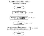
規準点3Dモデル作成部102は、地上画像に写ったターゲットの位置のデータに基づいて3次元TINモデルにより構成される基準点3Dモデルを作成する。基準点3Dモデル作成部102は、図2のステップS104の処理を行う。ターゲット画像検出部103は、移動体画像の中からターゲットの画像を検出する。ターゲット画像検出部103は、図4のステップS203の処理を行う。
The reference point 3D
特徴点抽出部104は、移動体画像中から特徴点を抽出する。特徴点は、周囲から区別できる点であり、例えば、エッジ部分や周囲と色彩が異なっている部分が特徴点として抽出される。特徴点の抽出は、ソフトウェア処理により行われる。特徴点の抽出には、ソーベル、ラプラシアン、プリューウィット、ロバーツなどの微分フィルタが用いられる。特徴点抽出部104は、図4のステップS204の処理を行う。また、特徴点抽出部104は、図6のステップS403における画像マッチング処理において、対象となる画像からの特徴点の抽出を行う。
The feature
対応点特定部105は、2枚の移動体画像中でそれぞれ個別に抽出された特徴点の対応関係を特定する。すなわち、一方の移動体画像中で抽出された特徴点と同じ特徴点を他方の移動体画像中で特定する処理を行う。この特徴点の対応関係を特定する処理は、例えば、図7に示すテンプレートマッチングを用いて行われる。対応関係の特定は、公知の他の方法を用いることも可能である。対応点特定部105は、図4のステップS205の処理を行う。特徴点の位置算出部106は、異なる静止画像間での対応関係が特定された特徴点の三次元座標を、前方交会法を用いて算出する。なお、基準点が特定されていない段階で得られる移動体画像中の特徴点の三次元位置は、相対位置となる。
The corresponding
相対3Dモデル作成部107は、移動体画像から画像検出されたターゲットの画面座標値、および移動体画像から得られた特徴点の三次元位置に基づき、相対3Dモデルを作成する。相対3Dモデル作成部107は、図4のステップS208の処理を行う。
The relative 3D
相対3Dモデルは、以下のようにして作成される。まず、ターゲット画像検出部103が移動体画像の中から検出したターゲットの画面位置と一致(あるいは最も近接)する特徴点(対応点特定部105が特定した特徴点)を探索する。次に、探索された特徴点の三次元位置を特徴点の位置算出部106が算出した結果から取得し、この三次位置を当該ターゲットの位置とする。この処理をターゲット画像検出部103が検出した全てのターゲットに関して行う。なお、この処理において、当該ターゲットが特徴点として抽出されていれば、当該ターゲットの三次元位置は、特徴点の位置算出部106によって算出されているので、その値が用いられる。こうして、ターゲット画像検出部103が検出した複数のターゲットの三次元位置(相対三次元位置)が求まり、各ターゲットの三次元位置を頂点とした三次元TINモデルが相対3Dモデルとして得られる。
The relative 3D model is created as follows. First, the target
3Dモデルの対応関係特定部108は、基準点3Dモデルと相対3Dモデルの対応関係の特定を行う。3Dモデルの対応関係特定部108は、図5に示すフローチャートに係る処理を行う。類似判定指標算出部109は、基準点3Dモデルと相対3Dモデルの対応関係の特定を行う際に用いる図形の形状の類似性を定量的に評価するパラメータである類似判定指標を算出する。形状の類似判定部110は、類似判定指標に基づいて、基準点3Dモデルを構成するTINの三角形と相対3Dモデルを構成するTINの三角形との類似性を判定する。なお、3Dモデルの対応関係特定部108が行う基準点3Dモデルと相対3Dモデルの対応関係を求める処理は、上記のTINモデルを利用する方法以外に、他の実施形態で説明する方法を用いることもできる。
The
対応点の位置情報取得部111は、対応関係が特定された基準点3Dモデルと相対3Dモデルの対応する点の情報に基づき、相対3Dモデルを構成する点の三次元位置の情報を取得する。すなわち、基準点3Dモデルを構成する点の位置(TS等で計測した地図座標系等の特定の座標系における位置:絶対位置)は既知であるので、基準点3Dモデルと相対3Dモデルとの対応関係が特定されることで、相対3Dモデルを構成する点の三次元位置(絶対位置)の情報を取得できる。対応点の位置情報取得部111は、図5のステップS312の処理を行う。 The position information acquisition unit 111 of corresponding points acquires information of three-dimensional positions of points constituting a relative 3D model based on information of corresponding points of the reference point 3D model and the relative 3D model whose correspondence is specified. That is, since the positions of points constituting the reference point 3D model (positions in a specific coordinate system such as the map coordinate system measured by TS etc .: absolute positions) are known, the correspondence between the reference point 3D model and the relative 3D model By specifying the relationship, it is possible to obtain information on the three-dimensional position (absolute position) of the points constituting the relative 3D model. The position information acquisition unit 111 of the corresponding point performs the process of step S312 in FIG.
探索領域設定部112は、基準点3Dモデルを構成する点の位置情報に基づき、移動体画像中に基準点(ターゲット)を探索するための探索領域を設定する。画像の向き調整部113は、地上画像と移動体画像中で設定された探索領域の画像との向きを合わせる処理を行う。画像の向きを揃えることで、後述の画像マッチング部114で行われる処理の精度を高めることができる。画像の向き調整部113は、図6のステップS402の処理を行う。 The search area setting unit 112 sets a search area for searching for the reference point (target) in the moving object image based on the position information of the points constituting the reference point 3D model. The image orientation adjustment unit 113 performs processing of aligning the orientation of the ground image with the image of the search area set in the moving object image. By aligning the direction of the image, the accuracy of the process performed by the image matching unit 114 described later can be enhanced. The image orientation adjustment unit 113 performs the process of step S402 in FIG.
画像マッチング部114は、地上画像と移動体画像中で設定された探索領域の画像(拡大画像)との対応関係を求める処理を行う。処理の方法は、対応関係特定部105で行われる処理と同じである。画像マッチング部114は、図6のステップS403の処理を行う。基準点位置情報取得部115は、地上画像と移動体画像中で設定された探索領域の画像との対応関係に基づき、移動体画像中でのターゲットの位置(基準点の位置)を特定する。この処理により、移動体画像中でのターゲットの位置が特定される。基準点位置情報取得部115は、図6のステップS404の処理を行う。
The image matching unit 114 performs processing for obtaining the correspondence between the ground image and the image (enlarged image) of the search area set in the moving object image. The method of processing is the same as the processing performed by the
3Dモデル作成部116は、特徴点抽出部104で抽出され、対応点の位置算出部106でその三次元位置が算出された特徴点に基づいて三次元モデルを作成する。例えば、UAVから撮影された航空写真に基づく土木工事現場の三次元モデルの作成が行なわれる。三次元モデルを作成する技術については、例えば、特開2014−35702号公報や特開2012−230594号公報に記載された技術が利用される。特開2014−35702号公報には、異なる視点から得られた2枚のステレオ画像から抽出される三次元点群位置データに基づく三次元モデルの作成について記載され、特開2012−230594号公報には、レーザスキャナから得られた三次元点群位置データが対象であるが、三次元点群位置データから三次元モデルを作成する技術について記載されている。移動体画像中でのターゲットの三次元位置が特定されることで、3Dモデル作成部116が作成する3Dモデルにスケール(実寸法)が与えられる。
The 3D model creation unit 116 creates a three-dimensional model based on the feature points extracted by the feature
(地上側で行われる処理)
図2には、地上側で行われる処理の手順の一例が示されている。ここでは、土木工事現場の三次元モデルを作成する場合を説明する。なお、図2におけるステップS104で行われる処理を実行するためのプログラムは、適当な記憶媒体や記憶領域に記憶されており、図1に示すハードウェアによって実行される。
(Process performed on the ground side)
An example of the procedure of the process performed on the ground side is shown by FIG. Here, the case of creating a three-dimensional model of a civil engineering work site will be described. A program for executing the process performed in step S104 in FIG. 2 is stored in an appropriate storage medium or storage area and executed by the hardware shown in FIG.
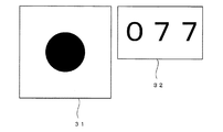
処理が開始されると、測量対象となる範囲におけるターゲットの設置が行なわれる(ステップS101)。図3には、使用されるターゲットの一例として円形ターゲット31が示されている。円形ターゲット31は、画像として認識し易ように、白地の正方形の中に黒丸が表示された構造を有している。黒丸の中心の位置が基準点の位置として画像認識される。また、位置の測量は、黒丸の中心を基準として行われる。 When the process is started, installation of a target in a range to be surveyed is performed (step S101). In FIG. 3, a circular target 31 is shown as an example of the target used. The circular target 31 has a structure in which black circles are displayed in squares on a white background so as to be easily recognized as an image. The position of the center of the black circle is recognized as the position of the reference point. Also, the survey of the position is performed based on the center of the black circle.
符号32は、円形ターゲット31を他の円形ターゲットから識別する数字が表示された識別プレートである。識別プレート32は、円形ターゲット31の近くに配置される。図3には、識別プレート32に識別番号として数字077が表示されているが、この識別番号は、複数ある円形ターゲット31毎に異なる数値のものが使用される。なお、円形ターゲット31と識別プレート32を一体化してもよい。ターゲットに関しては、例えば、日本国特許第4828125号公報に記載されているものを利用できる。
ターゲットの設置(ステップS101)を行ったら、地上において各ターゲットを撮影し、地上で撮影したターゲットの画像(地上画像)を得る(ステップS102)。この際、地上画像の撮影範囲が概略10m四方の領域が写るように画角(撮影範囲)を設定し、更に極力撮影視野の中心に円形ターゲット31が写るように撮影を行う。ターゲットの撮影は、ターゲットの近くから、図2に例示する円形ターゲット31と識別プレート32が明瞭に写るように行う。撮影を行う機材は特に限定されないが、TS(トータルステーション)付属のカメラ、スマートフォンに内蔵されたカメラ、デジタルカメラ等が挙げられるが、簡便性でいえば、スマートフォンに内蔵されたカメラやデジタルカメラが好適である。
After setting the targets (step S101), each target is photographed on the ground, and an image (ground image) of the target photographed on the ground is obtained (step S102). At this time, the angle of view (shooting range) is set so that an area of approximately 10 m square is captured in the shooting range of the ground image, and shooting is performed such that the circular target 31 is captured at the center of the shooting field of view as much as possible. The imaging of the target is performed from near the target so that the circular target 31 and the
また、撮影したターゲットの三次元位置の計測を行なう(ステップS102)。ターゲットの位置の測定は、TSを用いた測定、高精度GNSS装置を用いた測定、スマートフォン等のGNSS機能を利用した位置測定技術を利用した測定が挙げられる。 Also, the three-dimensional position of the photographed target is measured (step S102). The measurement of the position of the target includes a measurement using TS, a measurement using a high-precision GNSS device, and a measurement using a position measurement technology using a GNSS function such as a smartphone.
ターゲットの位置の計測には、以下の態様がある。
(1)全てのターゲットの位置の計測をTSおよび/または高精度GNSS装置を用いて行う。
(2)一部のターゲットの位置の計測をTSおよび/または高精度GNSS装置を用いて行い、他のターゲットの位置の計測は、スマートフォン等のGNSS機能を用いて行う。
There are the following modes for measuring the position of the target.
(1) Measure the position of all targets using TS and / or high precision GNSS equipment.
(2) The measurement of the position of a part of targets is performed using TS and / or a high-precision GNSS device, and the measurement of the positions of other targets is performed using a GNSS function such as a smartphone.
精度を確保する観点からは、(1)の態様が好ましいが、コストおよび手間の観点からは、(2)の態様を採用してもよい。なお、最終的に得られる三次元モデルの精度を確保するためには、ステレオ画像を構成する2枚の移動体画像中で最低4カ所以上の精度の確保された基準点(ターゲット)が必要であるので、そのようになるにように、TSおよび/または高精度GNSS装置を用いたターゲット位置の計測を行なう。もちろん、TSおよび/または高精度GNSS装置を用いた方法でなくても、計測位置の精度の確保できる位置計測方法であれば、それを採用することができる。複数配置したターゲットの位置と画像を得たら、そのデータを適当な記憶媒体に記憶する。ここで、ターゲットおよび識別プレートの画像データ、ターゲットの識別番号、およびターゲット(基準点)の位置の情報は関連付けして記憶しておく。 Although the aspect of (1) is preferable from the viewpoint of securing accuracy, the aspect of (2) may be adopted from the viewpoint of cost and labor. In order to ensure the accuracy of the finally obtained three-dimensional model, it is necessary to secure at least four or more reference points (targets) in the two mobile object images constituting the stereo image. As such, target position measurements are performed using TS and / or high precision GNSS equipment. Of course, even if it is not a method using TS and / or a high-precision GNSS device, any position measurement method that can ensure the accuracy of the measurement position can be adopted. Once the positions and images of the plurality of arranged targets are obtained, the data is stored in an appropriate storage medium. Here, the image data of the target and the identification plate, the identification number of the target, and the information of the position of the target (reference point) are stored in association with each other.
ターゲットの位置データと画像データを得たら、それらのデータをデータ受付部101で受け付け、測量データ処理装置100に入力する(ステップS103)。データを受け付けたら、測量データ処理装置100を用いてターゲットの位置を頂点とした三次元TINモデルを作成する(ステップS104)。TINは、不整三角形網( triangulated irregular network)と呼ばれるもので、不整三角形により対象をモデル化したものである。この処理では、ステップS102で得たターゲットの三次元位置情報を三次元空間上にプロットしてゆき、その位置を頂点とした不整三角形網を形成することで三次元TINモデルを得る。以下において、ステップS104で得た三次元TINモデルを基準点3Dモデルと称する。基準点3Dモデルを得たら、図2の処理を終了する。
After obtaining position data and image data of the target, the
(UAV側の処理)
以下、図2の処理で得た基準点3Dモデルと比較される相対3Dモデルを得るための処理の一例を説明する。図4には、相対3Dモデルを得るための処理の一例が示されている。なお、図4におけるステップS203〜S208で行われる処理を実行するためのプログラムは、適当な記憶媒体や記憶領域に記憶されており、図1に示すハードウェアによって実行される。
(Process on the UAV side)
Hereinafter, an example of a process for obtaining a relative 3D model to be compared with the reference point 3D model obtained by the process of FIG. 2 will be described. FIG. 4 shows an example of a process for obtaining a relative 3D model. A program for executing the processing performed in steps S203 to S208 in FIG. 4 is stored in an appropriate storage medium or storage area and executed by the hardware shown in FIG.
測位量対象地域へのターゲットの設置が完了したら、UAVによる測量対象地域の上空からの撮影を行う(ステップS201)。UAVは、GNSSを用いた自身の位置計測装置、IMU(慣性航法装置)、カメラを搭載し、予め定めた飛行経路を自律飛行しながら特定の時間間隔(例えば、1〜3秒毎)で地上を撮影する。このUAVから地上を撮影した画像を移動体画像と呼ぶ。得られた移動体画像の画像データは、撮影時間、撮影時のUAVの位置と姿勢(つまり、カメラの位置と姿勢)のデータと関連付けされ、飛行ログに格納される。飛行ログは、UAV内の記憶媒体(HDDや固体電子デバイスの記憶媒体)に記憶される。飛行ログは、飛行終了後に回収され、データ受付部101から測量データ処理装置100に入力される(ステップS202)。ステップS202の後、測量データ処理装置100は、ステップS203以下の処理を実行する。
When the installation of the target in the positioning amount target area is completed, the UAV performs imaging from above the survey target area (step S201). The UAV is equipped with its own position measurement device using GNSS, IMU (Inertial Navigation System), and camera, and performs autonomous flight on a predetermined flight path, while at specific time intervals (for example, every 1 to 3 seconds) on the ground. To shoot. An image of the ground taken from the UAV is called a moving object image. The image data of the obtained moving object image is associated with the data of shooting time and the position and posture of the UAV at the time of shooting (that is, the position and posture of the camera), and is stored in the flight log. The flight log is stored in a storage medium (a storage medium of an HDD or a solid electronic device) in the UAV. The flight log is collected after the flight ends, and is input from the
飛行ログから移動体画像のデータを得たら、複数ある移動体画像のそれぞれにおいてターゲットの画像の検出を行う(ステップS203)。この処理は、ソフトウェアによる画像解析処理によって行われる。この段階では、全てのターゲットを検出する必要はなく、検出し易い状態で写っているターゲットの画像を検出すればよい。したがって、この処理ではターゲットの未検出や検出不良(一部検出等の完全でない検出)が許容される。また、程度問題であるが、ターゲットの誤検出があってもよい。 When the data of the moving object image is obtained from the flight log, the image of the target is detected in each of a plurality of moving object images (step S203). This processing is performed by image analysis processing by software. At this stage, it is not necessary to detect all the targets, but it is sufficient to detect an image of the targets appearing in an easily detectable state. Therefore, in this process, non-detection or detection failure (incomplete detection such as partial detection) of the target is tolerated. Also, although there is a degree of problem, there may be false detection of a target.
次に、各移動体画像から特徴点の抽出を行う(ステップS204)。各移動体画像から特徴点を抽出したら、時間軸上で隣接する2枚の移動体画像の間、すなわちステレオ画像を構成する2枚の移動体画像の間で対応する特徴点の対応関係を求める処理が行なわれる(ステップS205)。ここで、ステレオ画像を構成する2枚の移動体画像は、異なる視点から重複する対象を撮影したものが選択される。 Next, feature points are extracted from each moving object image (step S204). Once the feature points are extracted from each moving object image, the correspondence relationship between the corresponding feature points is determined between two adjacent moving object images on the time axis, that is, between the two moving object images constituting the stereo image. A process is performed (step S205). Here, as the two mobile object images constituting the stereo image, those obtained by photographing overlapping objects from different viewpoints are selected.
特徴点の対応関係の特定は、テンプレートマッチングを用いて行う。テンプレートマッチングとしては、残差逐次検定法(SSDA:Sequential Similarity Detection Algorithm)、相互相関係数法などが挙げられる。以下、テンプレートマッチングの一例を説明する。テンプレートマッチングは、2つの座標系における画像の座標データを相互に比較し、両者の相関関係により、2つの画像の対応関係を求める方法である。テンプレートマッチングでは、2つの視点それぞれから見た画像の特徴点の対応関係が求められる。図7は、テンプレートマッチングの原理を説明する説明図である。この方法では、図示するように、N1×N1画素のテンプレート画像を、それよりも大きいM1×M1画素の入力画像内の探索範囲(M1−N1+1)2上で動かし、下記数1で示される相互相関関数C(a,b)が最大となるような(つまり相関の程度が最大となるような)テンプレート画像の左上位置を求める。
The specification of the correspondence of feature points is performed using template matching. As template matching, a residual similarity test (SSDA: Sequential Similarity Detection Algorithm), a cross correlation coefficient method, etc. may be mentioned. Hereinafter, an example of template matching will be described. Template matching is a method in which coordinate data of images in two coordinate systems are compared with each other, and the correspondence between the two images is determined by the correlation between the two. In template matching, the correspondence between feature points of an image viewed from each of two viewpoints is obtained. FIG. 7 is an explanatory view for explaining the principle of template matching. In this method, as shown, a template image of N 1 × N 1 pixels is moved over a search range (M 1 −N 1 +1) 2 within the larger M 1 × M 1 pixel input image, The upper left position of the template image in which the cross correlation function C (a, b) represented by the

上記の処理は、一方の画像の倍率を変えながら、また回転させながら行われる。そして、相関関係が最大となった条件で、両画像の一致する領域が求まり、更にこの領域における特徴点を抽出することで、対応点の検出が行われる。 The above process is performed while changing the magnification of one image and rotating it. Then, under the condition that the correlation is maximized, the matching region of both images is obtained, and the feature point in this region is extracted to detect the corresponding point.
テンプレートマッチングを用いることで、比較する2つの画像の一致する部分が特定でき、2つの画像の対応関係を知ることができる。この方法では、2つ画像の相関関係が最大となるように両者の相対的な位置関係が定められる。2つの画像の相関関係は、両画像の特徴点によって決まる。2つの画像間の対応関係を求める技術については、例えば特開2013−178656号公報や特開2014−35702号公報に記載されている技術を利用することができる。なお、特開2013−178656号公報や特開2014−35702号公報には、特徴点の抽出に係る技術、特徴点の三次元位置を求める技術についても記載されており、これらの技術は、本願明細書中で説明する技術に利用できる。 By using template matching, matching portions of two images to be compared can be identified, and the correspondence between the two images can be known. In this method, the relative positional relationship between the two images is determined so as to maximize the correlation between the two images. The correlation between the two images is determined by the feature points of both images. As a technique for obtaining the correspondence between two images, for example, techniques described in Japanese Patent Application Laid-Open No. 2013-178656 and Japanese Patent Application Laid-Open No. 2014-35702 can be used. Note that Japanese Patent Application Laid-Open No. 2013-178656 and Japanese Patent Application Laid-Open No. 2014-35702 also describe a technology relating to feature point extraction and a technology for obtaining a three-dimensional position of a feature point, and these techniques are described in the present application. It can be used for the techniques described in the specification.
ステレオ画像を構成する2枚の移動体画像間での特徴点の対応関係の特定を行ったら、特徴点の三次元位置の算出を行う(ステップS206)。特徴点の三次元位置の算出は、図8に示す前方方交会法を用いて行う。以下、前方交会法を用いて特徴点の位置の算出を行う原理を説明する。 After specifying the correspondence of feature points between two moving object images constituting a stereo image, the three-dimensional position of the feature points is calculated (step S206). The calculation of the three-dimensional position of the feature point is performed using the forward cross method shown in FIG. Hereinafter, the principle of calculating the position of the feature point using the forward intersection method will be described.
いま、第1の移動体画像と第2の移動体画像があり、この2つの移動体画像間で対応する特徴点Pが特定されているとする。ここで、第1の移動体画像の撮影時におけるカメラの位置O1と姿勢、第2の移動体画像の撮影時におけるカメラの位置O2と姿勢は飛行ログのデータから既知である。また、第1の移動体画像に写った特徴点Pの画面座標値p1(x1,y1)と第2の移動体画像に写った特徴点Pの画面座標値p2(x2,y2)とは、各移動体画像から取得できる。 Now, it is assumed that there are a first moving body image and a second moving body image, and a corresponding feature point P is specified between the two moving body images. Here, the position O 1 and the posture of the camera at the time of shooting of the first moving body image, the position O 2 and the posture of the camera at the time of shooting of the second mobile object image is known from the data in the flight log. In addition, the screen coordinate value p 1 (x 1 , y 1 ) of the feature point P captured in the first moving body image and the screen coordinate value p 2 (x 2 , x 2 , y 2 ) can be obtained from each moving object image.
ここで、O1とp1(x1,y1)を結ぶ方向線と、O2とp2(x2,y2)を結ぶ方向線を設定し、この2つの方向線の交点Pの座標を算出することで、交点Pに位置する特徴点の三次元位置が求められる。この原理により、移動体画像から抽出した特徴点の三次元位置が算出される。この算出は、各移動体画像から抽出された全ての特徴点に対して行われる。 Here, a direction line connecting O 1 and p 1 (x 1 , y 1 ) and a direction line connecting O 2 and p 2 (x 2 , y 2 ) are set, and an intersection point P of these two direction lines By calculating the coordinates, the three-dimensional position of the feature point located at the intersection point P can be obtained. By this principle, the three-dimensional position of the feature point extracted from the moving object image is calculated. This calculation is performed on all feature points extracted from each moving object image.
特徴点の位置を得たら、ステップS203で既に各移動体画像中から検出されているターゲットに対応する特徴点の位置(三次元位置)を取得する(ステップS207)。例えば、図8のモデルにおいて、p1の画面座標値の位置でターゲットが検出されたとする。この場合、点Pまたはその近傍の特徴点の三次元座標値を取得することで、左側の静止画像(移動体画像)から検出された画面座標値p1のターゲットの三次元位置が得られる。なお、この段階では、実寸法が与えられていないので、得られる三次元位置の座標値は相対値となる。上述した三次元位置の算出は、検出された全てのターゲットに対して行われる。 After obtaining the position of the feature point, the position (three-dimensional position) of the feature point corresponding to the target already detected in each moving object image is obtained in step S203 (step S207). For example, in the model of FIG. 8, it is assumed that a target is detected at the position of the screen coordinate value of p1. In this case, by acquiring the three-dimensional coordinate values of the feature point at or near the point P, the three-dimensional position of the target of the screen coordinate value p1 detected from the left still image (moving object image) can be obtained. At this stage, since the actual dimensions are not given, the coordinate values of the obtained three-dimensional position are relative values. The calculation of the three-dimensional position described above is performed for all the detected targets.
そして、取得したターゲット(ステップS203で移動体画像中から検出したターゲット)の位置を頂点とした三次元TINモデルを作成し、相対3Dモデルを得る(ステップS208)。この相対3Dモデルは、実寸法が与えられていない相対モデルとなる。以下、相対3Dモデルを作成する際の処理の具体的な一例を説明する。まず、ステップS203で検出されたターゲットの画面位置と一致(あるいは最も近接)する特徴点(ステップS204で抽出され、ステップS205で特定された特徴点)を探索する。次に、探索された特徴点の三次元位置をステップS206の結果から取得する。なお、この段階における特徴点の三次元位置は、相対位置である。この処理をステップS203で検出した全てのターゲットに関して行う。 Then, a three-dimensional TIN model having the position of the acquired target (target detected from the moving object image at step S203) as a vertex is created to obtain a relative 3D model (step S208). This relative 3D model is a relative model for which actual dimensions are not given. Hereinafter, a specific example of processing when creating a relative 3D model will be described. First, a feature point (feature point extracted in step S204 and identified in step S205) that matches (or is closest to) the screen position of the target detected in step S203 is searched. Next, the three-dimensional position of the searched feature point is acquired from the result of step S206. The three-dimensional position of the feature point at this stage is a relative position. This process is performed on all targets detected in step S203.
なお、この処理において、当該ターゲットが特徴点として抽出されていれば、当該ターゲットの三次元位置は、ステップS206において算出されているので、その値が用いられる。こうして、ステップS203で検出された複数のターゲットの三次元位置(相対三次元位置)が求まる。そして、移動体画像中から検出された複数のターゲットの三次元位置を頂点とした三次元TINモデルが相対3Dモデルとして得られる。一例ではあるが、以上の処理がステップS208において行われる。 In this process, if the target is extracted as a feature point, the three-dimensional position of the target is calculated in step S206, and the value is used. Thus, the three-dimensional positions (relative three-dimensional positions) of the plurality of targets detected in step S203 are obtained. Then, a three-dimensional TIN model having vertices at three-dimensional positions of a plurality of targets detected from the moving object image is obtained as a relative 3D model. Although the above is one example, the above process is performed in step S208.
(基準点3Dモデルと相対3Dモデルのマッチング)
ここでは、図2の処理で得た基準点3Dモデルと図4の処理で得た相対3Dモデルとの対応関係を求め、相対3Dモデルにおける基準点(ターゲットの設置位置)の位置を取得する処理について説明する。この処理では、基準点3Dモデルと相対3Dモデルの点の配置に関する類似性を定量的に評価する。そしてこの定量評価の結果を利用して基準点3DモデルのTINを構成する点と相対3DモデルのTINを構成する点との対応関係を求める。
(Match reference point 3D model and relative 3D model)
Here, a process of obtaining the correspondence between the reference point 3D model obtained by the process of FIG. 2 and the relative 3D model obtained by the process of FIG. 4 and acquiring the position of the reference point (target installation position) in the relative 3D model Will be explained. In this process, the similarity regarding the arrangement of points of the reference point 3D model and the relative 3D model is quantitatively evaluated. Then, using the result of this quantitative evaluation, the correspondence between the point that constitutes the TIN of the reference point 3D model and the point that constitutes the TIN of the relative 3D model is determined.
図5には、上記の処理を実行する手順の一例が示されている。なお、図5における処理を実行するためのプログラムは、適当な記憶媒体や記憶領域に記憶されており、図1に示すハードウェアによって実行される。 FIG. 5 shows an example of the procedure for executing the above-mentioned processing. A program for executing the process in FIG. 5 is stored in an appropriate storage medium or storage area and executed by the hardware shown in FIG.
まず、図2の処理で得た基準点3Dモデルと、図4の処理で得た相対3Dモデルを取得し(ステップS301)、ついで取得した2つのモデルの向きを合わせる(ステップS302)。ここでは、飛行ログにおけるIMUのデータから対象となる移動体画像の撮影時におけるカメラの向きの情報を取得し、それに基づいて相対3Dモデルの向きを基準点3Dモデルの向きに合わせる。 First, a reference point 3D model obtained by the process of FIG. 2 and a relative 3D model obtained by the process of FIG. 4 are obtained (step S301), and then the directions of the two obtained models are matched (step S302). Here, information of the camera direction at the time of shooting of the target mobile object image is acquired from the data of IMU in the flight log, and based on it, the direction of the relative 3D model is adjusted to the direction of the reference point 3D model.
図9(A)には、特定の視点から見た相対3Dモデル(左側)と基準点3Dモデル(右側)とが示されている。図9において、黒丸●が相対3Dモデルと基準点3Dモデルとで共通に抽出されている基準点(ターゲット位置)であり、白丸○が相対3Dモデルの作成時に未検出で、基準点3Dモデルの側で認識されている基準点(ターゲット位置)である。 FIG. 9A shows a relative 3D model (left side) and a reference point 3D model (right side) viewed from a specific viewpoint. In FIG. 9, black circles ● are reference points (target positions) extracted in common with the relative 3D model and the reference point 3D model, and white circles ○ are not detected when creating the relative 3D model, and the reference points 3D model It is a reference point (target position) recognized on the side.
まず、相対3Dモデルの側で点(TINを構成する頂点の一つ)を選択する(ステップS303)。そして、選択点と他の点を頂点とする三角形を形成し、その類似判定指標を算出する(ステップS304)。図9(B)の左側には、相対3Dモデルにおいて点が選択され、その点を頂点する三角形が選択された状態が示されている。 First, a point (one of the vertices constituting the TIN) is selected on the side of the relative 3D model (step S303). Then, a triangle having the selected point and another point as vertices is formed, and the similarity determination index thereof is calculated (step S304). On the left side of FIG. 9B, a state is shown in which a point is selected in the relative 3D model and a triangle that vertexes the point is selected.
以下、類似判定指標について説明する。類似判定指標は、着目した三角形と他の三角形との類似性を評価するための指標である。すなわち、ある三角形と類似な形状の三角形を探し出すために利用される指標である。図10には、三角形の頂点ES,E1,E2が示されている。ここで、ESがステップS303で選択された着目点に対応する。この場合、類似判定指標は、(L1,L2,θ)となる。 Hereinafter, the similarity determination index will be described. The similarity determination index is an index for evaluating the similarity between a focused triangle and another triangle. That is, it is an index used to find a triangle having a shape similar to a certain triangle. In FIG. 10, triangle vertices E S , E 1 and E 2 are shown. Here, E S corresponds to the target point selected in step S303. In this case, the similarity determination index is (L 1 , L 2 , θ).
ステップS304の後、基準点3Dモデルの側の全ての点に関して、ある点を頂点とした全ての三角形の選択、更に当該三角形の類似判定指標の算出を行う(ステップS305)。そして、ステップS304で求めた類似判定指標とステップS305で求めた類似判定指標を用いて両モデルで類似する三角形を選択する(ステップS306)。図9(B)には、左側の相対3Dモデル側の三角形に類似する三角形が右側の基準点3Dモデルの側から選択された場合が示されている。 After step S304, for all points on the reference point 3D model side, selection of all triangles with a certain point as a vertex and calculation of a similarity determination index of the triangle are performed (step S305). Then, using the similarity determination index obtained in step S304 and the similarity determination index obtained in step S305, a triangle that is similar in both models is selected (step S306). FIG. 9B shows a case where a triangle similar to the triangle on the left side of the relative 3D model is selected from the side of the reference point 3D model on the right side.
ステップS306で行われる類似の判定は、以下のようにして行われる。まず、相対3Dモデル側の類似判定指標を(L1,L2,θ)、基準点3Dモデルの側の類似判定指標を(T1,T2,φ)とする。ここで、T1はL1に対応する長さで、T2はL2に対応する長さで、φはθに対応する角度である。そして、基準の長さLS、T S として、三角形の辺の長さの差Δmiを数2から求める。 The similar determination performed in step S306 is performed as follows. First, the similarity determination index on the relative 3D model side is (L 1 , L 2 , θ), and the similarity determination index on the reference point 3D model side is (T 1 , T 2 , φ). Here, T 1 is a length corresponding to L 1 , T 2 is a length corresponding to L 2 , and φ is an angle corresponding to θ. The reference length L S, as T S, determining the difference Delta] m i of the length of the sides of a triangle from a few 2.
![]()
![]()
また、着目している2辺のなす角度の差Δaiを数3から計算する。
![]()
![]()
ここで、類似度Sは、各モデル間のセットの残差j(Δmi,Δai)として、数4で計算される。
ここで、n=2であり、rはGibbs分布の係数であり、LS=L 1、TS=T1として計算する。数4において、類似度が高い程、S=1に近くなる。ステップS306では、数4を用いて相対3Dモデル側で設定された三角形に類似する三角形を基準点3Dモデルの側から探索する。 Here, n = 2 and r is a coefficient of the Gibbs distribution, and is calculated as L s = L 1 and T s = T 1 . In Equation 4, the higher the similarity, the closer to S = 1. In step S306, a triangle similar to the triangle set on the relative 3D model side is searched from the side of the reference point 3D model using Expression 4.
ここで、基準点3Dモデルの側から類似する三角形が複数選択されてもよい。数4には、当然誤差があるので、基準点3Dモデル側で有意な差が認められない複数の三角形が見つかる場合もあり得るからである。 Here, a plurality of similar triangles may be selected from the side of the reference point 3D model. Naturally, since there is an error in Equation 4, it is possible that a plurality of triangles with no significant difference can be found on the reference point 3D model side.
ステップS306の後、ステップS307に進む。ステップS307では、相対3Dモデル側と基準点3Dモデル側とで類似として選択された三角形が予め規定された数の組(例えば6組)以上であるか否かが判定される。なお、ステップS307の判定の基準となる規定の組数(閾値)の値を大きくすると、基準点3Dモデルと相対3Dモデルの対応関係を求める精度が高くなる(あるいは対応関係を誤って求めてしまう可能性が低くなる)が、演算の負担は増大する。よって、ステップS307で利用する閾値は、対象とする基準点の数、マッチング精度、演算を行うハードウェアの性能、許容される演算時間等に鑑みて決定される。勿論、この閾値を可変とし、状況に応じて設定を変える態様も可能である。 After step S306, the process proceeds to step S307. In step S307, it is determined whether or not the triangles selected as similar on the relative 3D model side and the reference point 3D model side are equal to or more than a predetermined number of sets (for example, 6 sets). Note that if the value of the specified number of sets (threshold value), which is the reference of the determination in step S307, is increased, the accuracy of obtaining the correspondence between the reference point 3D model and the relative 3D model becomes high (or the correspondence is incorrectly obtained. The possibility is reduced), but the computational burden is increased. Therefore, the threshold value used in step S307 is determined in view of the number of target reference points, matching accuracy, performance of hardware that performs calculation, allowable calculation time, and the like. Of course, it is also possible to make this threshold variable and change the setting according to the situation.
TINモデルでは多数の三角形が形成されるので、2つのモデルで位置が異なるが偶然一致する三角形がある可能性は高い。そもそも誤差が含まれている場合、この可能性はさらに高くなる。したがって、TINを構成する三角形の一致に基づく、2つのTINモデルの対応関係の特定の精度を高めるために、ステップS307の処理を行う。 Since a large number of triangles are formed in the TIN model, there is a high possibility that there are triangles which are different in position but coincident with each other in the two models. This possibility is even higher if errors are included in the first place. Therefore, the process of step S307 is performed to enhance the specific accuracy of the correspondence between the two TIN models based on the coincidence of the triangles constituting the TIN.
ステップS307の判定において、類似する三角形の組が規定の数以上ある場合、ステップS311に進み、そうでない場合はステップS308に進む。ステップS308では、ステップS303で選択した点を頂点とする別の三角形を更に選択する。この状態の一例が図9(C)に示されている。 If it is determined in step S307 that the number of sets of similar triangles is equal to or larger than the predetermined number, the process proceeds to step S311. If not, the process proceeds to step S308. In step S308, another triangle having the point selected in step S303 as a vertex is further selected. An example of this state is shown in FIG. 9 (C).
ステップS308の後、ステップS309に進み、ステップS308で選択した三角形を対象にステップS306と同様の処理を行う。そして、ステップS309の処理の結果、基準点3Dモデルから選択された新たな三角形が、ステップS306において基準点3Dモデルから選択された三角形と頂点を共有するか否か、の判定が行なわれる(ステップS310)。 After step S308, the process proceeds to step S309, and the same processing as step S306 is performed on the triangle selected in step S308. Then, as a result of the process of step S309, it is determined whether the new triangle selected from the reference point 3D model shares a vertex with the triangle selected from the reference point 3D model in step S306 (step S306) S310).
例えば、ステップS309で選択された三角形がステップS306において選択された三角形と頂点を共有していない場合、それは互いに離れた位置にある三角形であり、相対3Dモデルの側の三角形と本来対応する三角形ではない。この場合、ステップS310の判定がNOとなり、ステップS308に戻り、再度の三角形の選択が行なわれる。 For example, if the triangle selected in step S309 does not share a vertex with the triangle selected in step S306, then it is a triangle that is at a distance from each other, and the triangle originally corresponding to the triangle on the side of the relative 3D model Absent. In this case, the determination in step S310 is NO, and the process returns to step S308 to perform another triangle selection.
図9(C)には、相対3Dモデルの側の頂点を共有する2つの三角形に対応する2つの三角形が基準点3Dモデルの側で選択された場合が示されている。このような場合、ステップ310の判定はYESとなる。 FIG. 9C shows a case where two triangles corresponding to two triangles sharing the side vertex of the relative 3D model are selected on the side of the reference point 3D model. In such a case, the determination in step 310 is YES.
ステップS310の判定がYESの場合、ステップS307以下の処理を再度実行する。図9(D)に示すようにある程度の三角形網の一致性が得られた段階でステップS307の判定がYESとなり、ステップS311に進む。ステップS311では、相対3Dモデル側の各頂点と基準点3Dモデル側の各頂点との位置が整合するように、相対3Dモデルの縮尺を調整する。この際、向きの微調整を同時に行ってもよい。 If the determination in step S310 is YES, the process following step S307 is executed again. As shown in FIG. 9D, the determination in step S307 becomes YES at a stage where a certain degree of triangle network consistency is obtained, and the process proceeds to step S311. In step S311, the scale of the relative 3D model is adjusted so that the positions of the vertices on the relative 3D model side and the vertices on the reference point 3D model match. At this time, fine adjustment of the direction may be performed simultaneously.
ステップS311の後、ステップS312に進み、基準点3Dモデル側の各頂点の位置情報(この情報は、図2のステップS102で取得している)を対応する相対3Dモデル側の各頂点の位置情報として取得する。こうして、相対3Dモデルを構成する各頂点の位置の情報が得られる。また、図9の白丸○で示される相対3Dモデルの側では未知の基準点の相対3Dモデルにおける位置の情報も得られる。相対3Dモデルは、移動体画像に基づいて作成されているので、相対3Dモデルにおける基準点の三次元位置が特定されることで、移動体画像中における基準点の三次元位置(地図座標系における三次元位置)が特定される。なお、地図座標系というのは、GNSSや地形図を記述する際に利用される座標系のことである。TS等で行う測量の結果は、この地図座標系上で記述される。 After step S311, the process proceeds to step S312, and positional information of each vertex of the reference point 3D model side (this information is acquired in step S102 of FIG. 2) is corresponding positional information of each vertex of the relative 3D model side Get as. Thus, information on the position of each vertex constituting the relative 3D model is obtained. In addition, on the side of the relative 3D model indicated by the white circle 図 in FIG. 9, information on the position of the unknown reference point in the relative 3D model is also obtained. Since the relative 3D model is created on the basis of the moving object image, the three-dimensional position of the reference point in the relative 3D model is specified, whereby the three-dimensional position of the reference point in the moving object image (in the map coordinate system) Three-dimensional position is identified. The map coordinate system is a coordinate system used when describing GNSS and topographic maps. The result of the survey performed by TS etc. is described on this map coordinate system.
以下、移動体画像中における基準点の三次元位置を特定する処理の一例について図8を用いて説明する。この場合、点Pが相対3Dモデルにおける位置が特定された点(ターゲット位置:規準点)である。そして左側の画像と右側の画像が点Pをステレオ視したステレオ画像を構成する2枚の移動体画像である。ここで、各2枚の移動体画像における点Pの画面座標値p1とp2は、画像データから判る。したがって、左側の移動体画像のp1の画面位置にある点Pの三次元位置、および右側の移動体画像のp2の画面位置にある点Pの三次元位置が判る。以上の原理により、移動体画像中における基準点の三次元位置の特定が行なわれる。 Hereinafter, an example of processing for specifying the three-dimensional position of the reference point in the moving object image will be described using FIG. In this case, the point P is a relative position in the relative 3D model (target position: reference point). The image on the left and the image on the right are two moving object images constituting a stereo image of the point P viewed in stereo. Here, the screen coordinate values p1 and p2 of the point P in each of the two moving object images can be found from the image data. Therefore, the three-dimensional position of the point P at the screen position of p1 of the left moving body image and the three-dimensional position of the point P at the screen position of p2 of the moving body image on the right are known. According to the above principle, the three-dimensional position of the reference point in the moving object image is specified.
図5の処理では、TINを構成する三角形の類似性を利用して、基準点の位置が既知の基準点3Dモデルと基準点の位置が未知の相対3Dモデルとの対応関係を求める。そして、この対応関係を利用して、相対3Dモデルにおける各頂点の位置情報(基準点の位置情報))を基準点3Dモデルの各頂点の位置情報から取得する。 In the process of FIG. 5, the correspondence between the reference point 3D model whose position of the reference point is known and the relative 3D model whose position of the reference point is unknown is determined by using the similarity of triangles constituting TIN. Then, using this correspondence relationship, position information (position information of reference points) of each vertex in the relative 3D model is acquired from position information of each vertex of the reference point 3D model.
本実施形態によれば、基準点3Dモデルと相対3Dモデルとの対応関係を求めることで、相対3Dモデルにおけるターゲットの位置を取得できる。すなわち、基準点3Dモデルは、地上で計測したターゲットの位置に基づくモデルであり、各頂点のターゲットの位置(基準点の位置)は、既知である。それに対して、相対3Dモデルの各頂点を構成するターゲットの位置は、その相対位置関係は求められているが、絶対位置は相対3Dモデルを求めた段階では未知である。よって、基準点3Dモデルと相対3Dモデルとの対応関係が判ることで、基準点3Dモデルにおける頂点の位置から、相対3Dモデルにおける基準点の位置を特定できる。 According to this embodiment, the position of the target in the relative 3D model can be acquired by obtaining the correspondence between the reference point 3D model and the relative 3D model. That is, the reference point 3D model is a model based on the position of the target measured on the ground, and the position of the target at each vertex (the position of the reference point) is known. On the other hand, although the relative positional relationship of the position of the target constituting each vertex of the relative 3D model is determined, the absolute position is unknown at the stage of determination of the relative 3D model. Therefore, by knowing the correspondence between the reference point 3D model and the relative 3D model, the position of the reference point in the relative 3D model can be specified from the position of the vertex in the reference point 3D model.
(移動体画像中におけるターゲット位置の特定)
図5の処理を行うことで、相対3Dモデルにおけるターゲットの位置(地図座標系上における位置)が特定され、更に移動体画像中での基準点の位置(ターゲットの位置)の特定が行なわれる。ここでは、更に以下の処理を行うことで、移動体画像中で検出が確実に行われなかった基準点(ターゲット)の位置を精度よく特定できる処理の一例を説明する。図5の処理によって、相対3Dモデルにおけるターゲットの位置が特定可能となる。ここでは、図5の処理の結果を利用して画像マッチングを行い、移動体画像中からのターゲット位置の検出を行う。
(Identification of target position in moving object image)
By performing the process of FIG. 5, the position of the target (the position on the map coordinate system) in the relative 3D model is specified, and the position of the reference point (the position of the target) in the moving object image is further specified. Here, an example of processing that can accurately specify the position of the reference point (target) in the moving object image for which detection has not been reliably performed will be described by further performing the following processing. By the process of FIG. 5, the position of the target in the relative 3D model can be identified. Here, image matching is performed using the result of the process of FIG. 5 to detect a target position from the moving object image.
まず、図4のステップS203において、移動体画像中からのターゲットの検出を行っているが、そこで行われる検出は画像が鮮明に映っている等の検出が容易なターゲットを優先的に検出した粗検出処理であり、未検出ターゲットの存在は許容されている。ここでは、以下に述べる処理を行うことで、図4のステップS203で検出できなかったターゲットの検出(正確には、ターゲットの位置の検出)が可能となる。 First, in step S203 in FIG. 4, the target is detected from the moving object image, but the detection performed there is a rough detection of a target that is easy to detect, such as a clear image. It is a detection process, and the presence of an undetected target is tolerated. Here, by performing the process described below, it becomes possible to detect the target that could not be detected in step S203 of FIG. 4 (precisely, to detect the position of the target).
図6には、移動体画像中におけるターゲットの位置を特定する処理の一例が示されている。図6の処理では、地上画像と移動体画像のマッチングを調べることで、移動体画像中におけるターゲットの位置を特定する。なお、図6の処理を実行するためのプログラムは、適当な記憶媒体や記憶領域に記憶されており、図1に示すハードウェアによって実行される。 FIG. 6 shows an example of processing for specifying the position of the target in the moving object image. In the process of FIG. 6, the position of the target in the moving object image is specified by examining the matching between the ground image and the moving object image. A program for executing the process of FIG. 6 is stored in an appropriate storage medium or storage area, and is executed by the hardware shown in FIG.
この処理では、まず特定のターゲット推定位置を対象として、移動体画像中で探索範囲の設定を行う(ステップS401)。具体的には、地上画像の一つを選択し、この地上画像に対応する移動体画像の中の領域(この対応関係は、図5の処理で特定されている)を探索領域として設定する。すなわち、基準点3Dモデルの頂点の位置情報から得た、相対3Dモデルの頂点の位置を推定位置として、そこを中心に特定の範囲を探索領域として設定する。 In this process, first, a search range is set in a moving object image for a specific target estimated position (step S401). Specifically, one of the ground images is selected, and an area in the moving object image corresponding to the ground image (this correspondence is specified in the process of FIG. 5) is set as a search area. That is, the position of the vertex of the relative 3D model obtained from the position information of the vertex of the reference point 3D model is set as an estimated position, and a specific range is set as a search region around that position.
上記の処理について図8を用いて更に詳細に説明する。例えば、図8の点Pが相対3Dモデル中で推定された基準点(ターゲット位置)であるとする。この場合、左側の画像が当該相対3Dモデルの作成に用いたステレオ画像を構成する第1の移動体画像であり、右側の画像が当該相対3Dモデルの作成に用いたステレオ画像を構成する第2の移動体画像となる。そして、p1が左側の移動体画像中での点Pの画面座標値であり、p2が右側の移動体画像中での点Pの画面座標値となる。 The above process will be described in more detail with reference to FIG. For example, it is assumed that the point P in FIG. 8 is a reference point (target position) estimated in the relative 3D model. In this case, the image on the left side is the first moving object image that constitutes the stereo image used to create the relative 3D model, and the image on the right side constitutes the stereo image used to create the relative 3D model. It becomes a moving body image of Then, a screen coordinate value of the point P in the p 1 is the left side of the moving object image, p 2 is the screen coordinates of a point P in the right side of the moving object image.
ここで、点Pで示されるターゲット推定位置が得られることで、その位置に対応する左側の移動体画像中でのターゲット推定位置p1、および右側の移動体画像中でのターゲット推定位置p2が得られる。そして、ターゲット推定位置p1を中心とした探索領域の設定を行うことで、左側の移動体画像中におけるターゲットの探索範囲の設定が行われる。同様に、ターゲット推定位置p2を中心とした探索領域の設定を行うことで、右側の移動体画像中におけるターゲットの探索範囲の設定が行われる。 Here, by obtaining the target estimated position indicated by the point P, the target estimated position p 1 in the left moving object image corresponding to that position and the target estimated position p 2 in the right moving object image Is obtained. Then, by performing the setting of the search area around the target estimated position p 1, setting the search range of the target at the left side of the moving body image. Similarly, by performing the setting of the search area around the target estimated position p 2, setting the search range of the target at the right side of the moving object image.
また、上記の処理では、図9の黒丸●で示される位置に加えて白丸○で示される位置も対象として移動体画像中での探索領域の設定が行なわれる。ここで、白丸○部分は、移動体画像から画像検出されなかったターゲットの位置である(拡大画像を利用したより詳細な検出処理で検出される可能性はある)。したがって、図4のステップS203の処理の精度が多少低く、検出漏れがあっても、ステップS401の処理において、漏れなく探索領域の設定が行なわれる。またこのために、ステップS203の処理に過大な負担を要しない処理が可能となり、全体の処理の効率化が図れる。 Further, in the above process, in addition to the position indicated by the black circle in FIG. 9, the position indicated by the white circle is also set as the search area in the moving object image. Here, the white circle 部分 portion is the position of the target that was not detected from the moving object image (it may be detected by more detailed detection processing using the enlarged image). Therefore, even if the accuracy of the process of step S203 of FIG. 4 is somewhat low and there is a detection failure, the search area is set without omission in the process of step S401. Further, for this reason, it is possible to perform processing that does not require an excessive burden on the processing of step S203, and it is possible to improve the efficiency of the entire processing.
探索領域としては、例えばターゲットの推定位置を中心とした10m四方の範囲が選択される。なお、ここでの探索範囲の設定は、TSや高精度GNSSを用いた精度の高い位置計測を行なったターゲットを対象にして行う。 As the search area, for example, a 10 m square range centered on the estimated position of the target is selected. Here, the setting of the search range is performed on a target for which position measurement with high accuracy is performed using TS or high-accuracy GNSS.
探索領域の画像は、移動体画像の一部の狭い範囲を拡大した拡大画像となるので、後述する地上画像とのマッチングを高い精度で行うことができる。また、マッチングを行う領域が予め限定できるので、マッチングに要するハードウェアの負担を抑えることができ、演算の効率化、高精度化、低消費電力化といったメリットが得られる。 Since the image of the search area is an enlarged image obtained by enlarging a narrow range of a part of the moving object image, matching with a ground image described later can be performed with high accuracy. In addition, since the area in which the matching is performed can be limited in advance, the burden of hardware required for the matching can be suppressed, and merits such as improvement in calculation efficiency, high accuracy, and low power consumption can be obtained.
推定領域を設定したら射影変換を用いて地上画像の向きと移動体画像の向きとを揃える(ステップS402)。画像の向きを揃える方法としては、(1)地上画像の向きを移動体画像の向きに合わせる方法、(2)移動体画像の向きを地上画像に合わせる方法、(3)両画像の向きを特定の方向に揃える方法が挙げられる。 After setting the estimation region, the direction of the ground image and the direction of the moving object image are aligned using projective transformation (step S402). As a method of aligning the direction of the image, (1) the method of aligning the direction of the ground image to the direction of the moving body image, (2) the method of aligning the direction of the moving body image to the ground image, (3) specifying the direction of both images There is a way to align in the direction of
以下、画像の向きを揃える方法の例を説明する。なお、以下の説明では、UAVにカメラが鉛直真下の方向に向けて固定されてあるものとする。まず、(1)の方法の一例を説明する。この場合、地上画像に写った図3のターゲットの形状が正方形となるように地上画像に対して射影変換を施す。こうすることで、地上画像と移動体画像の両方を鉛直上方から見た状態での比較が可能となる。なお、UAVは飛行中に傾く場合があり、また撮影視野の周辺に行く程、真上から撮影した条件からのずれが生じるが、ここではその影響は無視する。 Hereinafter, an example of a method of aligning the orientation of the image will be described. In the following description, it is assumed that the camera is fixed to the UAV in the direction directly below the UAV. First, an example of the method (1) will be described. In this case, projective transformation is performed on the ground image so that the shape of the target shown in FIG. 3 in the ground image is a square. This makes it possible to compare both the ground image and the mobile object image as viewed from above vertically. Note that the UAV may tilt during flight, and as it gets closer to the periphery of the field of view, deviations from the conditions taken from directly above occur, but this effect is ignored here.
次に、(2)の方法の一例を説明する。この場合、地上画像に写った図3のターゲットの形状が正方形となるように地上画像を傾けていった場合を計算し、地上画像の向きと鉛直方向とがなす角度を算出する。このなす角度に基づいて移動体画像に射影変換を施し、地上画像と移動体画像の向きを揃える。 Next, an example of the method (2) will be described. In this case, the case where the ground image is tilted so that the shape of the target shown in FIG. 3 in the ground image becomes a square is calculated, and the angle between the direction of the ground image and the vertical direction is calculated. Projective transformation is performed on the moving object image based on the formed angle to align the directions of the ground image and the moving object image.
次に、(3)の方法の一例を説明する。例えば、着目している移動体画像の撮影時のカメラの姿勢が鉛直方向からずれているとする(この情報は、飛行ログから取得できる)。この場合、鉛直方向から見た状態となるように移動体画像を射影変換する。他方で地上画像の方も鉛直方向から見た状態となるように、すなわち地上画像に写った図3のターゲットの形状が正方形となるよう地上画像に射影変換を施す。こうして、地上画像と移動体画像の向きを揃える。 Next, an example of the method (3) will be described. For example, it is assumed that the posture of the camera at the time of shooting a moving object image of interest is shifted from the vertical direction (this information can be acquired from the flight log). In this case, the mobile object image is projective-transformed so as to be viewed from the vertical direction. On the other hand, the ground image is subjected to projective transformation so that the ground image is also viewed from the vertical direction, that is, the target shown in FIG. 3 in the ground image has a square shape. Thus, the directions of the ground image and the moving object image are aligned.
画像の向きを揃えたら、地上画像(画像1)と移動体画像の探索範囲の部分の画像(画像2)との対応関係を調べる処理を行う(ステップS403)。この処理としては、画像間のマッチングをとる技術、すなわち2つの画像間の対応関係を求める技術が利用される。例えば、比較対象の画像1と画像2からの特徴点の抽出を行い、次にテンププレートマッチングを用いて画像1の特徴点と画像2の特徴点の対応関係の特定を行うことで画像1と画像2のマッチングをとることができる。2つの画像間のマッチングをとる技術としては、例えば特開2013−178656号公報や特開2014−35702号公報に記載されている技術を利用することができる。なお、画像1と画像2のマッチングが取れない場合は、処理エラーとなり、当該探索領域を対象としたマッチングの処理を終了する。
When the directions of the images are aligned, processing is performed to check the correspondence between the ground image (image 1) and the image (image 2) of the search range portion of the moving object image (step S403). As this process, a technique of matching between images, that is, a technique of determining correspondence between two images is used. For example, feature points are extracted from the
ステップS403の処理では、画像1と画像2のマッチング(対応関係の特定)が行なわれる。この際、ターゲット画像は必ずしも必要としない(勿論、あってもよい)。例えば、ターゲット周辺の地形の形状や石ころ等の画像も画像1と画像2のマッチングに利用されるので、ターゲットの画像は必ずしも必要とされない。そのため、移動体画像側でターゲットの画像が認識できない、あるいは画像認識が不十分であっても移動体画像中でのターゲット位置(基準点の位置)の特定を行える。また、画像1と画像2に共通に写っているターゲット以外の画像もマッチングに利用されるので、ターゲットのみの画像検出を行う場合に比較して、移動体画像中におけるターゲット位置の特定精度を高くできる。
In the process of step S403, matching between the
画像1と画像2の対応関係を特定したら、画像1におけるターゲットの位置情報から画像2のターゲットの位置情報を取得する(ステップS404)。こうして画像のマッチングに基づく移動体画像における基準点の位置の特定が行なわれる。なお、図5の処理によって、移動体画像中での基準点の位置は一応特定されるが、更に図6に示す処理を行うことで、より精密な移動体画像中での基準点位置の特定が可能となる。また、画像2(移動体画像の一部を拡大した画像)でターゲットが必ずしも鮮明に写っていなくても、全体の画像のマッチングがとれていれば、画像2におけるターゲットの位置を高い精度で特定できる。すなわち、図4のステップS203において移動体画像中で正確に検出できなかったターゲットおよび未検出のターゲットの位置を、図6の処理を行うことで、移動体画像中で特定できる。
When the correspondence between the
ステップS403により画像1と画像2のマッチングが取れた段階で、画像1を、画像2の一部を拡大した拡大画像として利用することができる。すなわち、画像1は、画像2の一部を別視点から撮影した画像であり、しかもターゲットの間近から撮影している。よって、画像1と画像2のマッチングが取れた段階で、画像1を画像2の一部の拡大画像として取り扱うことができる。このことを利用して、画像2で明確でなかった画像を画像1で確認するといったことが行える。
When matching between the
ステップS403の後、他に探索領域とする候補があるか否か、が判定され(ステップS405)、他の探索領域の候補があれば、ステップS401以下の処理を繰り返し、他の探索領域の候補が無ければ、処理を終了する。 After step S403, it is determined whether there is another candidate for the search area (step S405). If there is another candidate for the search area, the process from step S401 is repeated, and another candidate for the search area is obtained. If there is no, the process ends.
以上の処理によれば、TINモデルの対応関係を利用して地上画像と移動体画像のマッチングを取ることで、移動体画像中でのターゲット位置(基準点)の特定が行なえる。移動体画像中で複数の基準点を特定することで、移動体画像から得られる三次元モデルに実寸法が与えられる。なお、移動体画像に基づく三次元モデルの作成は、図11の3Dモデル作成部116で行われるが、その処理の詳細は公知の技術であるので、説明は省略する。この処理の詳細については、例えば、特開2014−35702号公報や特開2012−230594号公報に記載されている。 According to the above process, the target position (reference point) in the moving object image can be specified by matching the ground image and the moving object image using the correspondence relationship of the TIN model. Specifying a plurality of reference points in the moving object image gives real dimensions to the three-dimensional model obtained from the moving object image. The creation of a three-dimensional model based on a moving object image is performed by the 3D model creating unit 116 in FIG. 11, but the details of the process are known techniques, and thus the description thereof is omitted. The details of this process are described, for example, in Japanese Patent Application Laid-Open Nos. 2014-35702 and 2012-230594.
(まとめ)
以上述べたように、本実施形態では、地上に設置された複数の基準点のそれぞれを撮影することで得た第1の画像(上記の例では地上画像)のデータおよび前記複数の基準点の三次元位置のデータを含む第1のデータと、移動する移動体の一例であるUAVから前記複数の基準点を含む領域を撮影することで得た第2の画像(上記の例では移動体画像)のデータを含む第2のデータとを受け付けるデータ受付ステップ(ステップS103,S202)と、前記第1のデータに含まれる前記複数の基準点の三次元位置それぞれを頂点とする第1の形状モデル(上記の例では基準点3Dモデル)を作成する第1の形状モデル作成ステップ(ステップS104)と、前記第2の画像から前記基準点の画像を検出する基準点検出ステップ(ステップS203)と、前記第2の画像から検出された前記基準点のそれぞれを頂点とする第2の形状モデル(上記の例では相対3Dモデル)を作成する第2の形状モデル作成ステップ(ステップS208)と、前記第1の形状モデルと前記第2の形状モデルとの対応関係を求める第1の対応関係特定ステップ(図5の処理)と、前記第1の形状モデルと前記第2の形状モデルとの対応関係から前記第2の画像における前記基準点の推定位置を取得する基準点推定位置取得ステップ(ステップS312)と、前記基準点の前記推定位置に基づいて、前記第1の画像と前記第2の画像との対応関係を求める第2の対応関係特定ステップ(ステップS403)と、前記第1の画像と前記第2の画像との前記対応関係に基づき、前記第2の画像における前記基準点の三次元位置を特定する三次元位置特定ステップ(ステップS404)を行う。
(Summary)
As described above, in the present embodiment, the data of the first image (the ground image in the above example) obtained by photographing each of the plurality of reference points set on the ground and the plurality of reference points A second image obtained by photographing an area including the plurality of reference points from a first data including data of a three-dimensional position and a UAV that is an example of a moving object (a moving object image in the above example) Data receiving step (steps S103 and S202) for receiving the second data including the data of), and the first shape model having the respective three-dimensional positions of the plurality of reference points included in the first data as vertices A first shape model creation step (step S104) for creating (in the above example, a reference point 3D model), and a reference point detection step (step S) for detecting an image of the reference point from the second image. 03) and a second shape model creating step (step S208) for creating a second shape model (relative 3D model in the above example) having each of the reference points detected from the second image as a vertex A first correspondence determination step (processing of FIG. 5) for obtaining correspondence between the first shape model and the second shape model, and the first shape model and the second shape model. Acquiring an estimated position of the reference point in the second image from the correspondence relationship of the second image (step S312), and based on the estimated position of the reference point, the first image and the second The second correspondence specifying step (step S403) for obtaining correspondence between the second image and the second image based on the correspondence between the first image and the second image. Performing three-dimensional position specifying step (step S404) of specifying the three-dimensional position of the point.
すなわち、本実施形態では、設置されたターゲットを間近から撮影し、またその位置を計測する。この計測したターゲット位置を頂点として基準点3Dモデルを作成する。他方で、UAVが上空から撮影した画像(移動体画像)から検出されたターゲットの位置をステレオ三次元計測の原理で作成した三次元モデルから求め、TINで構成される相対3Dモデルを得る。そして、基準点3Dモデルと相対3Dモデルとの対応関係を求める。基準点3Dモデルでは、頂点を構成する各基準点の三次元位置は求められているので、この段階で相対3Dモデルにおける基準点の三次元位置が得らえる。 That is, in the present embodiment, the set target is photographed from close proximity, and its position is measured. A reference point 3D model is created with this measured target position as a vertex. On the other hand, the position of the target detected from the image (moving object image) captured from the sky by the UAV is determined from the three-dimensional model created by the principle of stereo three-dimensional measurement, to obtain a relative 3D model composed of TIN. Then, the correspondence between the reference point 3D model and the relative 3D model is determined. In the reference point 3D model, since the three-dimensional position of each reference point constituting the vertex is obtained, the three-dimensional position of the reference point in the relative 3D model can be obtained at this stage.
ここで、相対3Dモデルは、移動体画像に基づいて作成されている。したがって、相対3Dモデル上で基準点(ターゲット位置)の位置が特定されることで、その情報を移動体画像に対応させることで、移動体画像中での基準点の位置が特定される。具体的には、相対3Dモデルの特定の位置が当該3Dモデルのベースとなった移動体画像のどの部分に対応するのかが図8の原理から分かるので、相対3Dモデル上でターゲットの位置が取得されることで、移動体画像中でのターゲットの位置が取得される(ステップS312)。 Here, the relative 3D model is created based on the moving object image. Therefore, by specifying the position of the reference point (target position) on the relative 3D model, the position of the reference point in the moving object image is specified by making the information correspond to the moving object image. Specifically, since it is known from the principle of FIG. 8 which part of the moving object image on which the specific 3D model's relative position is based corresponds to that of the moving object image, the position of the target is obtained on the relative 3D model As a result, the position of the target in the moving object image is obtained (step S312).
ところで、相対3Dモデルに誤差が含まれる場合があり、また未検出および誤検出したターゲット位置(基準点位置)が含まれる可能性がある。他方で、基準点3Dモデルは、個々にターゲット位置を計測した結果を利用しているので、各頂点の基準点の位置の信頼性および精度は高い。そこで、基準点3Dモデルと相対3Dモデルとの対応関係から求めた相対3Dモデル上での基準点の位置情報を利用して、地上画像と移動体画像とのマッチングを行い、移動体画像中での基準点の位置の特定を行う。この処理により、移動体画像における更に精度の高い基準点の位置情報が得られる(ステップS404)。 By the way, the relative 3D model may include an error, and may include the undetected and erroneously detected target position (reference point position). On the other hand, since the reference point 3D model utilizes the result of measuring the target position individually, the reliability and accuracy of the position of the reference point at each vertex is high. Therefore, using the position information of the reference point on the relative 3D model obtained from the correspondence between the reference point 3D model and the relative 3D model, matching between the ground image and the mobile object image is performed, and the mobile object image is detected. Identify the position of the reference point of By this processing, the position information of the reference point with higher accuracy in the moving object image is obtained (step S404).
図6の処理では、3Dモデル同士のマッチングから得られた移動体画像中における基準点の位置の情報に基づき移動体画像中で探索領域を設定する。そして、この探索領域と地上画像とのマッチングを行うことで、探索領域での基準位置の特定(ターゲット位置の特定)を行う。図5の処理でも移動体画像中で基準点の位置を特定できるが、図5の処理に加えて更に図6の処理を行うことで、更に精度よく移動体画像中における基準点の特定が行なえる。また、図6の処理を行うことで、移動体画像中で明瞭にターゲットが写っていなかった等の理由により、図5の処理では特定できなかった基準点の位置を移動体画像中で特定できる。 In the process of FIG. 6, a search area is set in the moving object image based on the information of the position of the reference point in the moving object image obtained from the matching of the 3D models. Then, the search area and the ground image are matched to identify the reference position in the search area (specify the target position). Although the processing of FIG. 5 can also specify the position of the reference point in the moving object image, by further performing the processing of FIG. 6 in addition to the processing of FIG. 5, the reference point in the moving object image can be specified more accurately. Ru. Further, by performing the process of FIG. 6, the position of the reference point which can not be identified by the process of FIG. 5 can be identified in the moving object image because the target is not clearly shown in the moving object image. .
図6の処理では、移動体画像中で明確に現れておらず、従来の自動検出では未検出となる可能性のあるターゲットの位置を確実に移動体画像中で特定できる。また、自動検出では誤検出の問題が生じるが、地上画像は、近くから撮影した画像でターゲットが明瞭に写っているので、ターゲットの誤検出の発生確率は極めて低い。よって、地上画像と移動体画像とのマッチング結果を利用することで、移動体画像中におけるターゲット位置の特定に誤りが生じる確率を低くできる。 In the process of FIG. 6, the position of a target that does not clearly appear in the mobile object image and may not be detected by the conventional automatic detection can be identified in the mobile object image with certainty. In addition, although the problem of false detection occurs in automatic detection, since the ground image clearly shows the target in an image taken from near, the probability of false detection of the target is extremely low. Therefore, by using the matching result between the ground image and the moving object image, it is possible to reduce the probability that an error occurs in specifying the target position in the moving object image.
以上の理由により、本実施形態では、ソフトウェア処理を用いた自動検出により、UAVから撮影した移動体画像中での基準点の位置情報の取得を高精度に行うことができる。このため、従来の技術における作業者による基準点の正誤の確認作業やマニュアルで基準点を指定する作業の負担を大きく軽減できる。 For the above reasons, in the present embodiment, the automatic detection using software processing makes it possible to obtain the position information of the reference point in the mobile object image captured from the UAV with high accuracy. For this reason, it is possible to greatly reduce the burden of the operation of checking the correctness of the reference point by the operator in the prior art and the operation of manually specifying the reference point.
2.第2の実施形態
ステップS304における類似判定指標の算出では、TINを構成する三角形を対象としたが、着目した特定の点から他の点への4以上の線分に関して数2〜数4の算出を行ってもよい。この場合、着目した点と周囲の点との相対位置関係が定量的に評価され、当該着目点が特徴づけられる。すなわち、類似判定指標として着目点と4点以上の他の点との関係を定量的に評価するパラメータが得られる。着目点と他の点との関係の多様性が多くなる程、当該着目点を特徴づけるパラメータの顕著性、すなわち当該着目点を他の点から定量的に差別化できるようになるので、基準点3Dモデルと相対3Dモデルとのマッチング精度を更に高めることができる。
2. Second Embodiment In the calculation of the similarity determination index in step S304, although the triangle constituting the TIN is targeted, calculation of the
3.第3の実施形態
基準点3Dモデルと相対3Dモデルとの対応を求める方法の他の例を説明する。以下の処理は、図5の処理の代わりに、あるいは図5の処理に併用して利用できる。
3. Third Embodiment Another example of a method of obtaining the correspondence between the reference point 3D model and the relative 3D model will be described. The following processing can be used instead of the processing of FIG. 5 or in combination with the processing of FIG.
まず、基準点3Dモデルおよび相対3Dモデルを特定の方向(例えば鉛直上方)から見たものを考える。図12(A)には、5点の基準点●により構成される基準点3Dモデルを特定の角度から見た状態が示されている。ここで、4つの基準点を選択し、四角形を作成する。この一例が図12(B)の左側に示されている。四角形を選択したら、この四角形の重心の位置○を求める。次に、求めた重心の位置から全ての基準点までの距離と角度θの値を計算し、それを図12の右側に示すヒストグラムにまとめる。 First, consider the reference point 3D model and the relative 3D model as viewed from a specific direction (for example, vertically upward). FIG. 12A shows a state in which a reference point 3D model configured by five reference points ● is viewed from a specific angle. Here, four reference points are selected to create a square. An example of this is shown on the left side of FIG. 12 (B). After selecting a quadrilateral, the position 重心 of the center of gravity of this quadrilateral is determined. Next, the distances from the determined position of the center of gravity to all reference points and values of the angle θ are calculated, and they are summarized in the histogram shown on the right side of FIG.
上記の作業を他の組み合わせの4点で構成される四角形についても同様に行う。図12(B)の場合と異なる四角形を選択した場合の一例が図12(C)に示されている。四角形を構成する基準点の組み合わせを変えると、ヒストグラムも異なる形状となる。以上の処理を設定できる範囲の数の四角形に関して行う。 The above operation is similarly performed on a quadrangle formed by four points of other combinations. An example in the case of selecting a quadrangle different from the case of FIG. 12 (B) is shown in FIG. 12 (C). If the combination of the reference points constituting the rectangle is changed, the histogram also has a different shape. The above processing is performed on a set number of quadrangles.
基準点3Dモデルについて図12に係る処理を行ったら、同様の処理を相対3Dモデルに関しても行う。そして、一方の群のヒストグラムの中の一つに着目し、この着目したヒストグラムに類似したヒストグラムを他方の群の中から探索する。例えば、基準点3Dモデルの側のヒストグラムの一つに着目し、このヒストグラムに類似するヒストグラムを相対3Dモデルの側のヒストグラムの中から探索する。 When the process according to FIG. 12 is performed on the reference point 3D model, the same process is performed on the relative 3D model. Then, focusing on one of the histograms of one group, a histogram similar to the focused histogram is searched from the other group. For example, focusing on one of the histograms on the side of the reference point 3D model, a histogram similar to this histogram is searched from among the histograms on the side of the relative 3D model.
ここで、ヒストグラムを横軸方向でひとつずつずらしながら比較することで、回転の影響を吸収できる。この際、残差が最小となるように一方のヒストグラムに係数(スケール)をかける。通常、着目しているヒストグラムに類似するヒストグラムは複数見つかる。そこで、投票を行って、類似している上位の複数(例えば10個)を選択する。例えば、基準点3Dモデルの側の四角形に着目している場合、この四角形に係るヒストグラムに類似する相対3Dモデル側の上位複数のヒストグラムを選択する。 Here, the influence of rotation can be absorbed by comparing the histograms while shifting them one by one in the horizontal axis direction. At this time, one histogram is multiplied by a factor (scale) so as to minimize the residual. Usually, a plurality of histograms similar to the histogram of interest are found. Therefore, a vote is made to select a plurality of similar higher ranks (for example, 10). For example, when focusing on a quadrangle on the side of the reference point 3D model, a plurality of top histograms on the relative 3D model side similar to the histogram relating to the quadrilateral are selected.
次に、選択されたヒストグラムに対応する四角形の情報を取得する。すなわち、着目している基準点3Dモデル側の四角形を構成する4点の基準点の情報と、相対3Dモデル側から選択された複数の四角形の情報を取得する。そして、対応すると推定される2つの四角形の間の変換係数を求める。変換係数は、一方を他方に合わせるのに必要な回転と移動の変換係数、あるいは射影変換係数である。変換係数を求めたら、この変換係数を用いて基準点3Dモデル側の四角形(着目している四角形)と相対3Dモデル側から選択された類似が推定される四角形に関して、一方を他方(または他方を一方)に変換し、両者の頂点の位置の比較を行う。 Next, square information corresponding to the selected histogram is acquired. That is, information on four reference points constituting a square on the reference point 3D model side of interest and information on a plurality of squares selected from the relative 3D model side are acquired. Then, a conversion coefficient between two squares estimated to correspond is obtained. The transform coefficients are rotation and movement transform coefficients required to bring one into the other, or projective transform coefficients. Once the conversion factor is determined, one of the reference point 3D model-side quadrangle (target square) and the relative similarity estimation estimated quadrangle from the relative 3D model side are calculated using this conversion factor. On the other hand, and compare the positions of the two vertices.
例えば、相対3Dモデル側に変換した基準点3Dモデル側の四角形(着目している四角形)と相対3Dモデル側の第1の候補の四角形との比較、相対3Dモデル側に変換した基準点3Dモデル側の四角形(着目している四角形)と相対3Dモデル側の第2の候補の四角形との比較、相対3Dモデル側に変換した基準点3Dモデル側の四角形(着目している四角形)と相対3Dモデル側の第3の候補の四角形との比較、・・・を行う。 For example, comparison of the quadrangle on the reference point 3D model side converted to the relative 3D model side (square in focus) with the first candidate quadrangle on the relative 3D model side, the reference point 3D model converted to the relative 3D model side Comparison between the square on the side (squares of interest) and the second candidate square on the relative 3D model side, the reference point converted to the relative 3D model side The square on the 3D model side (squares of interest) and relative 3D Comparison with the third candidate quadrangle on the model side is performed.
ここで、比較した四角形の頂点を構成する点同士の位置の残差を求め、残差の最も少ない組の点を対応する点として決定する。こうして、基準点3Dモデルを構成する基準点の中の4点に対応する相対3Dモデルを構成する4点が求められる。 Here, the residuals of the positions of the points forming the apexes of the compared quadrilaterals are obtained, and the points of the smallest set of residuals are determined as the corresponding points. Thus, four points constituting a relative 3D model corresponding to four points among the reference points constituting the reference point 3D model are obtained.
上記の処理を選択した四角形の数の分行なうことで、基準点3Dモデル側で特定されている全ての点に関して、対応する相対3Dモデル側の点を求める。 By performing the above processing for the number of selected quadrilaterals, the corresponding relative 3D model side points are obtained for all points specified on the reference point 3D model side.
上記の説明(図12の例)では、四角形を利用する場合を説明したが、三角形や5角形等の多角形を選択し、その重心を求めてヒストグラムを作成してもよい。 In the above description (the example of FIG. 12), although the case of using a quadrilateral has been described, a polygon such as a triangle or a pentagon may be selected, and the center of gravity may be determined to create a histogram.
4.第4の実施形態
この例では、ある角度から見た基準点3Dモデルを構成する全点の平均値を重心とし、図12の場合と同様なヒストグラムを作成する。他方で、ある角度から見た相対3Dモデルを構成する全点の平均値を重心とし、図12の場合と同様なヒストグラムを作成する。そして、得られた2つのヒストグラムを角度軸方向でずらしながら、両者の対応関係を探索する。この際の処理の詳細は、第3の実施形態の場合と同じである。対応関係がとれた段階で相対3Dモデルを構成する点に対応する基準点3Dモデルの点の位置情報を取得し、相対3Dモデルを構成する点の三次元位置情報を取得する。
4. Fourth Embodiment In this example, the average value of all the points constituting the reference point 3D model viewed from a certain angle is set as the center of gravity, and a histogram similar to that of FIG. 12 is created. On the other hand, the average value of all the points constituting the relative 3D model viewed from a certain angle is used as the center of gravity, and a histogram similar to the case of FIG. 12 is created. Then, while shifting the two obtained histograms in the direction of the angle axis, the correspondence between the two is searched. The details of the process in this case are the same as in the third embodiment. At the stage when the correspondence is established, positional information of points of the reference point 3D model corresponding to the points constituting the relative 3D model is acquired, and three-dimensional positional information of points constituting the relative 3D model is acquired.
5.第5の実施形態
規準点3Dモデルを構成する各点(基準点)と相対3Dモデルを構成する各点との対応関係を求める手法として、RANSAC(Random sample consensus)やLMEDS(Least Median Squares)を用いることもできる。例えば、以下の手法を用いて、2つのモデルの対応関係を求める。
5. Fifth Embodiment As a method of determining the correspondence between each point (reference point) constituting the reference point 3D model and each point constituting the relative 3D model, RANSAC (Random sample consents) and LMEDS (Least Median Squares) are used. It can also be used. For example, the correspondence between two models is determined using the following method.
(1)変換係数が求められる分以上の点数をランダムに選択する。
例えば、未知変量+1として、アフィン変換であれば7点以上、射影変換であれば9点以上、ヘルマート変換(平行移動と回転)であれば5点以上の点をランダムに選択する。
(2)点同士の組み合わせをランダムに選択し、その際の変換係数を求める。
(3)最も多かった(近かった)変換係数を順位別に並べる。
(4)順位の高いものから変換を施す。
(5)変換した後、各点での残差を求める。
(6)最も残差が少なかったものを候補とする。
(7)基準点の隣接関係から妥当性があるかをチェックする。
(8)もしだめなら、次に順位の高いものを変換して残差を求める。
(9)これを繰り返して、(7)に一番あったものを選び対応点とする。
(10)マッチングにより詳細マッチングを行う。
(1) Randomly select a score that is equal to or greater than the one for which the conversion coefficient is to be determined.
For example, as unknown
(2) A combination of points is randomly selected, and a conversion coefficient at that time is obtained.
(3) Arrange the most frequent (closest) transform coefficients by rank.
(4) Convert from the highest ranking one.
(5) After conversion, find the residual at each point.
(6) The candidate with the least residual is considered.
(7) Check whether there is validity from the adjacent relation of the reference points.
(8) If no, convert the next highest rank to find the residual.
(9) Repeat this, select the one that was the most in (7) as the corresponding point.
(10) Perform detailed matching by matching.
基準点3Dモデルと相対3Dモデルとの対応関係を求める方法として、2つの画像の対応関係を求める技術を利用することもできる。この技術に関しては、図4のステップS205の処理に関連して説明した技術を利用することができる。勿論、基準点3Dモデルと相対3Dモデルとの対応関係を求める方法としては、その他の公知の方法を用いることもできる。 As a method of obtaining the correspondence between the reference point 3D model and the relative 3D model, a technique of obtaining the correspondence between two images can also be used. With regard to this technology, the technology described in relation to the process of step S205 of FIG. 4 can be used. Of course, other known methods can also be used to obtain the correspondence between the reference point 3D model and the relative 3D model.
6.その他
移動体は、航空機に限定されず、車両や船舶であってよい。例えば、車両にカメラを搭載し、移動する車両から撮影を行って移動体画像を得ることもできる。上記の説明では、ターゲットに近接して配置された識別プレート32の識別番号を利用する処理について記載していないが、移動体画像中のターゲットの位置が特定された後で、その付近の拡大画像を得、そこから識別プレート32の識別番号を画像認識によって読み取り、対応するターゲット31の座標情報を取得してもよい。この場合、画像探索の範囲が極めて狭い範囲に絞られるので、識別プレート32の識別番号の画像検出は容易に行える。
6. Others The moving body is not limited to an aircraft, and may be a vehicle or a ship. For example, a camera can be mounted on a vehicle, and a moving object image can be obtained by shooting from a moving vehicle. Although the above description does not describe the process of using the identification number of the
本明細書で説明した技術では、地上画像と移動体画像とのマッチングが取れた段階で移動体画像中のターゲット付近の拡大画像として、地上画像が利用できる状態となる。地上画像は、移動体画像に比較して高精細であり、より明瞭にターゲットが写っている。したがって、地上画像と移動体画像とのマッチングが取れた段階で移動体画像を地上画像の拡大画像として取得し、そこからターゲットの画像を取得してもよい。 In the technique described in the present specification, when the ground image and the mobile object image are matched, the ground image can be used as an enlarged image near the target in the mobile object image. The ground image has high definition compared to the mobile object image, and the target is more clearly shown. Therefore, the mobile object image may be acquired as a magnified image of the ground image when the ground image and the mobile object image are matched, and the target image may be acquired therefrom.
図6のステップS404の処理において、ターゲットの位置情報でなく、ターゲットの識別情報(例えば、図3の識別プレートの記載された識別番号等)を取得してもよい。当該識別情報は、当該ターゲットの設置位置(計測位置)と関連付けされた上でデータ化されているので、ターゲットの識別情報を取得することは、ターゲットの位置情報を取得することと等価である。 In the process of step S404 of FIG. 6, identification information of the target (for example, the identification number written on the identification plate of FIG. 3, etc.) may be acquired instead of the position information of the target. Since the identification information is converted into data after being associated with the installation position (measurement position) of the target, acquiring the identification information of the target is equivalent to acquiring the position information of the target.
基準点として専用のターゲットを用いる例を示したが、画像として識別可能なものであれば、基準点を示す対象物として利用することができる。例えば、電柱、道路標識、マンホール等を基準点として用いることもできる。 Although an example in which a dedicated target is used as a reference point is shown, if it can be identified as an image, it can be used as an object indicating the reference point. For example, a telephone pole, a road sign, a manhole or the like can be used as a reference point.
基準点3Dモデルと相対3Dモデルとの対応関係を求める方法として、2つの画像の対応関係を求める技術を利用することもできる。この技術に関しては、図4のステップS205の処理に関連して説明した技術を利用することができる。勿論、基準点3Dモデルと相対3Dモデルとの対応関係を求める方法としては、その他の公知の方法を用いることもできる。 As a method of obtaining the correspondence between the reference point 3D model and the relative 3D model, a technique of obtaining the correspondence between two images can also be used. With regard to this technology, the technology described in relation to the process of step S205 of FIG. 4 can be used. Of course, other known methods can also be used to obtain the correspondence between the reference point 3D model and the relative 3D model.
Claims (11)
前記第1のデータに含まれる前記複数の基準点の三次元位置それぞれを頂点とする第1の形状モデルを作成する第1の形状モデル作成部と、
前記第2の画像から前記基準点の画像を検出する基準点検出部と、
前記第2の画像から検出された前記基準点のそれぞれを頂点とする第2の形状モデルを作成する第2の形状モデル作成部と、
前記第1の形状モデルと前記第2の形状モデルとの対応関係を求める第1の対応関係特定部と、
前記第1の形状モデルと前記第2の形状モデルとの対応関係から前記第2の画像における前記基準点の三次元位置を取得する基準点位置取得部と
を備えることを特徴とする測量データ処理装置。 First data including data of a first image obtained by photographing each of a plurality of reference points set on the ground and data of a three-dimensional position of the plurality of reference points; A data receiving unit that receives second data including data of a second image obtained by photographing an area including the reference point;
A first shape model generation unit that generates a first shape model having, as vertices, three-dimensional positions of the plurality of reference points included in the first data;
A reference point detection unit that detects an image of the reference point from the second image;
A second shape model creating unit that creates a second shape model having each of the reference points detected from the second image as a vertex;
A first correspondence specifying unit which obtains a correspondence between the first shape model and the second shape model;
A reference point position acquisition unit for acquiring the three-dimensional position of the reference point in the second image from the correspondence relationship between the first shape model and the second shape model; survey data processing apparatus.
前記第1の画像と前記第2の画像との前記対応関係に基づき、前記第2の画像における前記基準点の三次元位置を特定する三次元位置特定部と
を備えることを特徴とする請求項1または2に記載の測量データ処理装置。 A second correspondence specifying unit which obtains a correspondence between the first image and the second image based on the three-dimensional position of the reference point acquired by the reference point position acquiring unit;
A three-dimensional position specifying unit for specifying a three-dimensional position of the reference point in the second image based on the correspondence between the first image and the second image; The survey data processing apparatus according to 1 or 2.
前記第1の画像は、前記基準点を至近距離から撮影した画像であり、
前記第2の対応関係特定部は、前記第1の画像と前記基準点の特定位置に基づき前記第2の画像の一部を拡大した拡大画像との対応関係の特定を行うことを特徴とする請求項3に記載の測量データ処理装置。 The second image is a wide area image taken from an aircraft,
The first image is an image obtained by photographing the reference point from a close distance,
The second correspondence specifying unit specifies a correspondence between the first image and an enlarged image obtained by enlarging a part of the second image based on a specific position of the reference point. The survey data processing apparatus according to claim 3.
前記第2の画像上からは検出されなかった前記基準点の三次元位置が前記三次元位置特定部によって特定されることを特徴とする請求項3〜6のいずれか一項に記載の測量データ処理装置。 The first data includes data of a three-dimensional position of the reference point not detected from the second image;
The survey data according to any one of claims 3 to 6, wherein the three-dimensional position of the reference point not detected from the second image is specified by the three-dimensional position specifying unit. Processing unit.
前記第2の形状モデルは、視点の異なる複数の前記第2の画像に基づき交会法を用いて作成された3次元モデルに前記第2の画像中における前記基準点の位置を対応させることで作成された第2の三次元TINモデルであることを特徴とする請求項1〜7のいずれか一項に記載の測量データ処理装置。 The first shape model is a first three-dimensional TIN model having the three-dimensional positions of the plurality of reference points included in the first data as vertices.
The second shape model is created by making the position of the reference point in the second image correspond to a three-dimensional model created using the method of intersection based on the plurality of second images having different viewpoints. The survey data processing apparatus according to any one of claims 1 to 7, wherein the survey data processing apparatus is a second three-dimensional TIN model.
前記第1のデータに含まれる前記複数の基準点の三次元位置それぞれを頂点とする第1の形状モデルを作成する第1の形状モデル作成ステップと、
前記第2の画像から前記基準点の画像を検出する基準点検出ステップと、
前記第2の画像から検出された前記基準点のそれぞれを頂点とする第2の形状モデルを作成する第2の形状モデル作成ステップと、
前記第1の形状モデルと前記第2の形状モデルとの対応関係を求める第1の対応関係特定ステップと、
前記第1の形状モデルと前記第2の形状モデルとの対応関係から前記第2の画像における前記基準点の三次元位置を取得する基準点位置取得ステップと
を備えることを特徴とする測量データ処理方法。 First data including data of a first image obtained by photographing each of a plurality of reference points set on the ground and data of three-dimensional positions of the plurality of reference points, and the moving object from the moving object A data receiving step of receiving second data including data of a second image obtained by photographing an area including a plurality of reference points;
A first shape model creating step of creating a first shape model having, as vertices, respective three-dimensional positions of the plurality of reference points included in the first data;
A reference point detection step of detecting an image of the reference point from the second image;
A second shape model creating step of creating a second shape model having each of the reference points detected from the second image as a vertex;
A first correspondence determination step of determining a correspondence between the first shape model and the second shape model;
A reference point position acquiring step of acquiring the three-dimensional position of the reference point in the second image from the correspondence relationship between the first shape model and the second shape model; survey data processing Method.
コンピュータに
地上に設置された複数の基準点のそれぞれを撮影することで得た第1の画像のデータおよび前記複数の基準点の三次元位置のデータを含む第1のデータと、移動する移動体から前記複数の基準点を含む領域を撮影することで得た第2の画像のデータを含む第2のデータとを受け付けるデータ受付ステップと、
前記第1のデータに含まれる前記複数の基準点の三次元位置それぞれを頂点とする第1の形状モデルを作成する第1の形状モデル作成ステップと、
前記第2の画像から前記基準点の画像を検出する基準点検出ステップと、
前記第2の画像から検出された前記基準点のそれぞれを頂点とする第2の形状モデルを作成する第2の形状モデル作成ステップと、
前記第1の形状モデルと前記第2の形状モデルとの対応関係を求める第1の対応関係特定ステップと、
前記第1の形状モデルと前記第2の形状モデルとの対応関係から前記第2の画像における前記基準点の三次元位置を取得する基準点位置取得ステップと
を実行させることを特徴とする測量データ処理用プログラム。 A program that causes a computer to read and execute it,
First data including data of a first image obtained by photographing each of a plurality of reference points set on the ground on a computer and data of three-dimensional positions of the plurality of reference points, and a moving mobile A data receiving step of receiving a second data including data of a second image obtained by photographing an area including the plurality of reference points from the data;
A first shape model creating step of creating a first shape model having, as vertices, respective three-dimensional positions of the plurality of reference points included in the first data;
A reference point detection step of detecting an image of the reference point from the second image;
A second shape model creating step of creating a second shape model having each of the reference points detected from the second image as a vertex;
A first correspondence determination step of determining a correspondence between the first shape model and the second shape model;
A reference point position acquiring step of acquiring a three-dimensional position of the reference point in the second image from the correspondence relationship between the first shape model and the second shape model; Processing program.
Priority Applications (2)
| Application Number | Priority Date | Filing Date | Title |
|---|---|---|---|
| JP2015133736A JP6543520B2 (en) | 2015-07-02 | 2015-07-02 | Survey data processing apparatus, survey data processing method and program for survey data processing |
| US15/196,425 US10198632B2 (en) | 2015-07-02 | 2016-06-29 | Survey data processing device, survey data processing method, and survey data processing program |
Applications Claiming Priority (1)
| Application Number | Priority Date | Filing Date | Title |
|---|---|---|---|
| JP2015133736A JP6543520B2 (en) | 2015-07-02 | 2015-07-02 | Survey data processing apparatus, survey data processing method and program for survey data processing |
Publications (3)
| Publication Number | Publication Date |
|---|---|
| JP2017015598A JP2017015598A (en) | 2017-01-19 |
| JP2017015598A5 JP2017015598A5 (en) | 2018-08-09 |
| JP6543520B2 true JP6543520B2 (en) | 2019-07-10 |
Family
ID=57683111
Family Applications (1)
| Application Number | Title | Priority Date | Filing Date |
|---|---|---|---|
| JP2015133736A Active JP6543520B2 (en) | 2015-07-02 | 2015-07-02 | Survey data processing apparatus, survey data processing method and program for survey data processing |
Country Status (2)
| Country | Link |
|---|---|
| US (1) | US10198632B2 (en) |
| JP (1) | JP6543520B2 (en) |
Cited By (1)
| Publication number | Priority date | Publication date | Assignee | Title |
|---|---|---|---|---|
| KR102242366B1 (en) * | 2020-10-29 | 2021-04-21 | 한국건설기술연구원 | RTK drone based GRP auto-arrangement apparatus for digital map creation of earthwork site |
Families Citing this family (23)
| Publication number | Priority date | Publication date | Assignee | Title |
|---|---|---|---|---|
| US9903719B2 (en) * | 2013-09-03 | 2018-02-27 | Litel Instruments | System and method for advanced navigation |
| JP6767279B2 (en) * | 2017-02-09 | 2020-10-14 | 株式会社トプコン | Surveying system |
| CN106774422A (en) * | 2017-02-28 | 2017-05-31 | 成都紫瑞青云航空宇航技术有限公司 | A kind of unmanned plane recognition methods and system |
| US10431103B2 (en) * | 2017-04-11 | 2019-10-01 | T-Mobile Usa, Inc. | Three-dimensional network coverage modeling for UAVs |
| CN107607091A (en) * | 2017-08-31 | 2018-01-19 | 中国电力科学研究院 | A kind of method for measuring unmanned plane during flying flight path |
| EP3743886A4 (en) * | 2018-01-25 | 2021-11-03 | Geomni, Inc. | Systems and methods for rapid alignment of digital imagery datasets to models of structures |
| JP7048347B2 (en) * | 2018-02-23 | 2022-04-05 | 成典 田中 | Positional relationship determination device |
| US11248930B2 (en) * | 2018-03-02 | 2022-02-15 | International Business Machines Corporation | Microclimate wind forecasting |
| KR102144268B1 (en) * | 2018-07-02 | 2020-08-28 | 주식회사 유니디자인경영연구소 | A device for producing a 3D map for virtual reality using an image photographed by an unattended observation means and the method thereof |
| GB201812170D0 (en) * | 2018-07-26 | 2018-09-12 | Scape Tech Ltd | Method of model alignment through localisation usage |
| JP7301514B2 (en) | 2018-09-21 | 2023-07-03 | 日立建機株式会社 | Coordinate transformation system and working machine |
| CN109255341B (en) * | 2018-10-30 | 2021-08-10 | 百度在线网络技术(北京)有限公司 | Method, device, equipment and medium for extracting obstacle perception error data |
| AU2018426323B2 (en) * | 2018-11-21 | 2020-07-30 | Guangzhou Xaircraft Technology Co., Ltd. | Method and apparatus for planning sample points for surveying and mapping, control terminal, and storage medium |
| JP7227534B2 (en) * | 2019-06-18 | 2023-02-22 | 日本電信電話株式会社 | How to get absolute coordinates |
| CN114286923A (en) * | 2019-06-26 | 2022-04-05 | 谷歌有限责任公司 | Global coordinate system defined by data set corresponding relation |
| CN111699453A (en) * | 2019-07-01 | 2020-09-22 | 深圳市大疆创新科技有限公司 | Control method, device and equipment of movable platform and storage medium |
| JP7300915B2 (en) | 2019-07-16 | 2023-06-30 | 株式会社トプコン | surveying equipment |
| JP7300930B2 (en) | 2019-08-26 | 2023-06-30 | 株式会社トプコン | Survey data processing device, survey data processing method and program for survey data processing |
| US11531833B2 (en) * | 2020-01-16 | 2022-12-20 | Honeywell International Inc. | Creating a ground control point file using an existing landmark shown in images |
| WO2021221758A2 (en) | 2020-02-13 | 2021-11-04 | Skydio, Inc. | Performing 3d reconstruction via an unmanned aerial vehicle |
| CN111343082A (en) * | 2020-03-06 | 2020-06-26 | 梁冠岚 | Stereoscopic display method for micro robot cluster |
| CN113075714B (en) * | 2020-11-13 | 2021-12-21 | 中移(上海)信息通信科技有限公司 | Auxiliary positioning method, device and equipment based on reference point position |
| CN117940739A (en) * | 2021-10-28 | 2024-04-26 | 深圳市大疆创新科技有限公司 | Positioning method and device for movable platform |
Family Cites Families (6)
| Publication number | Priority date | Publication date | Assignee | Title |
|---|---|---|---|---|
| JP3441139B2 (en) * | 1993-12-27 | 2003-08-25 | 三井住友建設株式会社 | Photogrammetry method and control point indicating device used in the method |
| JP4077385B2 (en) * | 2003-09-19 | 2008-04-16 | コマツエンジニアリング株式会社 | Global coordinate acquisition device using image processing |
| FI117490B (en) * | 2004-03-15 | 2006-10-31 | Geodeettinen Laitos | Procedure for defining attributes for tree stocks using a laser scanner, image information and interpretation of individual trees |
| JP5356269B2 (en) * | 2010-01-29 | 2013-12-04 | 株式会社パスコ | Laser data filtering method and apparatus |
| JP2013096745A (en) | 2011-10-28 | 2013-05-20 | Hokuriku Kosoku Co Ltd | Three-dimensional model creation method |
| JP5963353B2 (en) * | 2012-08-09 | 2016-08-03 | 株式会社トプコン | Optical data processing apparatus, optical data processing system, optical data processing method, and optical data processing program |
-
2015
- 2015-07-02 JP JP2015133736A patent/JP6543520B2/en active Active
-
2016
- 2016-06-29 US US15/196,425 patent/US10198632B2/en active Active
Cited By (1)
| Publication number | Priority date | Publication date | Assignee | Title |
|---|---|---|---|---|
| KR102242366B1 (en) * | 2020-10-29 | 2021-04-21 | 한국건설기술연구원 | RTK drone based GRP auto-arrangement apparatus for digital map creation of earthwork site |
Also Published As
| Publication number | Publication date |
|---|---|
| JP2017015598A (en) | 2017-01-19 |
| US20170004345A1 (en) | 2017-01-05 |
| US10198632B2 (en) | 2019-02-05 |
Similar Documents
| Publication | Publication Date | Title |
|---|---|---|
| JP6543520B2 (en) | Survey data processing apparatus, survey data processing method and program for survey data processing | |
| JP6510247B2 (en) | Survey data processing apparatus, survey data processing method and program | |
| KR101933216B1 (en) | River topography information generation method using drone and geospatial information | |
| US8571265B2 (en) | Measurement apparatus, measurement method, and feature identification apparatus | |
| EP3023913A1 (en) | Crack data collection method and crack data collection program | |
| EP2660777A2 (en) | Image registration of multimodal data using 3D geoarcs | |
| US20090154793A1 (en) | Digital photogrammetric method and apparatus using intergrated modeling of different types of sensors | |
| EP3023912A1 (en) | Crack data collection apparatus and server apparatus to collect crack data | |
| US11551411B2 (en) | Data processor, data processing method, and data processing program for determining correspondence relationships between laser scanning point clouds | |
| JP6506032B2 (en) | Survey data processing apparatus, survey data processing method and program | |
| TW201830336A (en) | Position/orientation estimating device and position/orientation estimating method | |
| Tang et al. | Surveying, geomatics, and 3D reconstruction | |
| Maurice et al. | A photogrammetric approach for map updating using UAV in Rwanda | |
| JP6506031B2 (en) | Survey data processing apparatus, survey data processing method and program | |
| Al-Rawabdeh et al. | A robust registration algorithm for point clouds from UAV images for change detection | |
| Choi et al. | Precise geometric registration of aerial imagery and LIDAR data | |
| US20220148216A1 (en) | Position coordinate derivation device, position coordinate derivation method, position coordinate derivation program, and system | |
| RU2699940C1 (en) | Method of main pipeline route monitoring | |
| EP3894788A1 (en) | Method and system for generating an environment model for positioning | |
| Chuanxiang et al. | Automatic detection of aerial survey ground control points based on Yolov5-OBB | |
| Merkle et al. | Sensor evaluation for crack detection in concrete bridges | |
| KR100586815B1 (en) | System and method for measuring position of threedimensions | |
| US20230196601A1 (en) | Apparatuses and methods for determining the volume of a stockpile | |
| JP7399632B2 (en) | Photography processing device and photography processing method | |
| JP2009121945A (en) | Feature position measurement method |
Legal Events
| Date | Code | Title | Description |
|---|---|---|---|
| A521 | Request for written amendment filed |
Free format text: JAPANESE INTERMEDIATE CODE: A523 Effective date: 20180626 |
|
| A621 | Written request for application examination |
Free format text: JAPANESE INTERMEDIATE CODE: A621 Effective date: 20180626 |
|
| A977 | Report on retrieval |
Free format text: JAPANESE INTERMEDIATE CODE: A971007 Effective date: 20190227 |
|
| A131 | Notification of reasons for refusal |
Free format text: JAPANESE INTERMEDIATE CODE: A131 Effective date: 20190307 |
|
| A521 | Request for written amendment filed |
Free format text: JAPANESE INTERMEDIATE CODE: A523 Effective date: 20190423 |
|
| TRDD | Decision of grant or rejection written | ||
| A01 | Written decision to grant a patent or to grant a registration (utility model) |
Free format text: JAPANESE INTERMEDIATE CODE: A01 Effective date: 20190522 |
|
| A61 | First payment of annual fees (during grant procedure) |
Free format text: JAPANESE INTERMEDIATE CODE: A61 Effective date: 20190617 |
|
| R150 | Certificate of patent or registration of utility model |
Ref document number: 6543520 Country of ref document: JP Free format text: JAPANESE INTERMEDIATE CODE: R150 |
|
| R250 | Receipt of annual fees |
Free format text: JAPANESE INTERMEDIATE CODE: R250 |
|
| R250 | Receipt of annual fees |
Free format text: JAPANESE INTERMEDIATE CODE: R250 |