JP5963353B2 - Optical data processing apparatus, optical data processing system, optical data processing method, and optical data processing program - Google Patents
Optical data processing apparatus, optical data processing system, optical data processing method, and optical data processing program Download PDFInfo
- Publication number
- JP5963353B2 JP5963353B2 JP2012177504A JP2012177504A JP5963353B2 JP 5963353 B2 JP5963353 B2 JP 5963353B2 JP 2012177504 A JP2012177504 A JP 2012177504A JP 2012177504 A JP2012177504 A JP 2012177504A JP 5963353 B2 JP5963353 B2 JP 5963353B2
- Authority
- JP
- Japan
- Prior art keywords
- dimensional
- edges
- group
- dimensional model
- edge
- Prior art date
- Legal status (The legal status is an assumption and is not a legal conclusion. Google has not performed a legal analysis and makes no representation as to the accuracy of the status listed.)
- Active
Links
- 238000012545 processing Methods 0.000 title claims description 93
- 230000003287 optical effect Effects 0.000 title claims description 46
- 238000003672 processing method Methods 0.000 title description 2
- 238000004364 calculation method Methods 0.000 claims description 74
- 239000013598 vector Substances 0.000 claims description 55
- 238000000605 extraction Methods 0.000 claims description 37
- 239000000284 extract Substances 0.000 claims description 15
- 230000010354 integration Effects 0.000 claims description 13
- 238000000034 method Methods 0.000 description 116
- 238000005259 measurement Methods 0.000 description 94
- 230000008569 process Effects 0.000 description 56
- ATJFFYVFTNAWJD-UHFFFAOYSA-N Tin Chemical compound [Sn] ATJFFYVFTNAWJD-UHFFFAOYSA-N 0.000 description 30
- 238000010586 diagram Methods 0.000 description 20
- 230000006870 function Effects 0.000 description 13
- 238000002372 labelling Methods 0.000 description 11
- 230000009466 transformation Effects 0.000 description 11
- PXFBZOLANLWPMH-UHFFFAOYSA-N 16-Epiaffinine Natural products C1C(C2=CC=CC=C2N2)=C2C(=O)CC2C(=CC)CN(C)C1C2CO PXFBZOLANLWPMH-UHFFFAOYSA-N 0.000 description 8
- 238000012937 correction Methods 0.000 description 6
- 230000007423 decrease Effects 0.000 description 5
- 238000006073 displacement reaction Methods 0.000 description 4
- 238000011156 evaluation Methods 0.000 description 4
- 238000004891 communication Methods 0.000 description 3
- 238000005516 engineering process Methods 0.000 description 3
- 239000013589 supplement Substances 0.000 description 3
- 230000000295 complement effect Effects 0.000 description 2
- 239000011521 glass Substances 0.000 description 2
- 238000009434 installation Methods 0.000 description 2
- 239000000047 product Substances 0.000 description 2
- 230000008685 targeting Effects 0.000 description 2
- 238000013519 translation Methods 0.000 description 2
- 108010033272 Nitrilase Proteins 0.000 description 1
- 230000002159 abnormal effect Effects 0.000 description 1
- 230000009471 action Effects 0.000 description 1
- 238000013459 approach Methods 0.000 description 1
- 230000015572 biosynthetic process Effects 0.000 description 1
- 230000008859 change Effects 0.000 description 1
- 230000001186 cumulative effect Effects 0.000 description 1
- 230000007613 environmental effect Effects 0.000 description 1
- 230000001788 irregular Effects 0.000 description 1
- 239000004973 liquid crystal related substance Substances 0.000 description 1
- 230000004807 localization Effects 0.000 description 1
- 230000002093 peripheral effect Effects 0.000 description 1
- 239000004065 semiconductor Substances 0.000 description 1
- 230000001629 suppression Effects 0.000 description 1
Images


Classifications
-
- G—PHYSICS
- G01—MEASURING; TESTING
- G01B—MEASURING LENGTH, THICKNESS OR SIMILAR LINEAR DIMENSIONS; MEASURING ANGLES; MEASURING AREAS; MEASURING IRREGULARITIES OF SURFACES OR CONTOURS
- G01B11/00—Measuring arrangements characterised by the use of optical techniques
-
- G—PHYSICS
- G06—COMPUTING; CALCULATING OR COUNTING
- G06F—ELECTRIC DIGITAL DATA PROCESSING
- G06F18/00—Pattern recognition
- G06F18/20—Analysing
- G06F18/22—Matching criteria, e.g. proximity measures
-
- G—PHYSICS
- G06—COMPUTING; CALCULATING OR COUNTING
- G06T—IMAGE DATA PROCESSING OR GENERATION, IN GENERAL
- G06T15/00—3D [Three Dimensional] image rendering
- G06T15/10—Geometric effects
- G06T15/20—Perspective computation
-
- G—PHYSICS
- G06—COMPUTING; CALCULATING OR COUNTING
- G06T—IMAGE DATA PROCESSING OR GENERATION, IN GENERAL
- G06T17/00—Three dimensional [3D] modelling, e.g. data description of 3D objects
-
- G—PHYSICS
- G06—COMPUTING; CALCULATING OR COUNTING
- G06T—IMAGE DATA PROCESSING OR GENERATION, IN GENERAL
- G06T17/00—Three dimensional [3D] modelling, e.g. data description of 3D objects
- G06T17/05—Geographic models
-
- G—PHYSICS
- G06—COMPUTING; CALCULATING OR COUNTING
- G06T—IMAGE DATA PROCESSING OR GENERATION, IN GENERAL
- G06T17/00—Three dimensional [3D] modelling, e.g. data description of 3D objects
- G06T17/10—Constructive solid geometry [CSG] using solid primitives, e.g. cylinders, cubes
-
- G—PHYSICS
- G06—COMPUTING; CALCULATING OR COUNTING
- G06T—IMAGE DATA PROCESSING OR GENERATION, IN GENERAL
- G06T3/00—Geometric image transformations in the plane of the image
- G06T3/40—Scaling of whole images or parts thereof, e.g. expanding or contracting
- G06T3/403—Edge-driven scaling; Edge-based scaling
-
- G—PHYSICS
- G06—COMPUTING; CALCULATING OR COUNTING
- G06T—IMAGE DATA PROCESSING OR GENERATION, IN GENERAL
- G06T7/00—Image analysis
- G06T7/50—Depth or shape recovery
- G06T7/55—Depth or shape recovery from multiple images
- G06T7/593—Depth or shape recovery from multiple images from stereo images
-
- G—PHYSICS
- G06—COMPUTING; CALCULATING OR COUNTING
- G06V—IMAGE OR VIDEO RECOGNITION OR UNDERSTANDING
- G06V10/00—Arrangements for image or video recognition or understanding
- G06V10/40—Extraction of image or video features
- G06V10/44—Local feature extraction by analysis of parts of the pattern, e.g. by detecting edges, contours, loops, corners, strokes or intersections; Connectivity analysis, e.g. of connected components
-
- G—PHYSICS
- G06—COMPUTING; CALCULATING OR COUNTING
- G06T—IMAGE DATA PROCESSING OR GENERATION, IN GENERAL
- G06T2210/00—Indexing scheme for image generation or computer graphics
- G06T2210/56—Particle system, point based geometry or rendering
Landscapes
- Engineering & Computer Science (AREA)
- Physics & Mathematics (AREA)
- Theoretical Computer Science (AREA)
- General Physics & Mathematics (AREA)
- Geometry (AREA)
- Software Systems (AREA)
- Computer Graphics (AREA)
- Computer Vision & Pattern Recognition (AREA)
- Remote Sensing (AREA)
- Data Mining & Analysis (AREA)
- Multimedia (AREA)
- Computing Systems (AREA)
- Bioinformatics & Cheminformatics (AREA)
- General Engineering & Computer Science (AREA)
- Evolutionary Computation (AREA)
- Evolutionary Biology (AREA)
- Bioinformatics & Computational Biology (AREA)
- Artificial Intelligence (AREA)
- Life Sciences & Earth Sciences (AREA)
- Length Measuring Devices By Optical Means (AREA)
- Image Processing (AREA)
- Image Analysis (AREA)
Description
本発明は、光学データの処理技術に係り、異なる視点から得られた三次元データを統合して扱う技術に関する。 The present invention relates to a technique for processing optical data, and more particularly to a technique for integrating and handling three-dimensional data obtained from different viewpoints.
測定対象物にレーザー光を走査しつつ照射し、測定対象物の三次元位置を多数の点群位置データとして取得し、この点群位置データから当該測定対象物の三次元形状を生成する技術が知られている(例えば、特許文献1を参照)。点群位置データでは、二次元画像と三次元座標とが結び付けられている。すなわち、点群位置データでは、測定対象物の二次元画像のデータと、この二次元画像に対応付けされた複数の測定点(点群)と、この複数の測定点の三次元空間中の位置(三次元座標)とが関連付けされている。点群位置データを用いると、点の集合により測定対象物の外形を再現した三次元モデルを得ることができる。また、各点の三次元座標が判るので、各点の三次元空間中における相対位置関係が把握でき、画面表示した三次元モデルの画像を回転させたり、異なる視点から見た画像に切り替えたりする処理が可能となる。 A technology that irradiates a measurement object while scanning with laser light, acquires the three-dimensional position of the measurement object as a large number of point cloud position data, and generates a three-dimensional shape of the measurement object from the point cloud position data. It is known (see, for example, Patent Document 1). In the point cloud position data, a two-dimensional image and a three-dimensional coordinate are linked. That is, in the point cloud position data, two-dimensional image data of the measurement object, a plurality of measurement points (point group) associated with the two-dimensional image, and positions of the plurality of measurement points in the three-dimensional space. (Three-dimensional coordinates). By using the point cloud position data, it is possible to obtain a three-dimensional model that reproduces the outer shape of the measurement object using a set of points. In addition, since the three-dimensional coordinates of each point are known, the relative positional relationship of each point in the three-dimensional space can be grasped, and the image of the three-dimensional model displayed on the screen can be rotated or switched to an image viewed from a different viewpoint. Processing is possible.
一つの視点からの点群位置データの取得を考えた場合、測定対象物の形状や障害物に起因して、その視点から見て影となる部分の点群位置データは取得できない。この現象をオクルージョンといい、またこの影となる部分をオクルージョン部やオクルージョン部分という。また、通行人や通行する車両、木々の揺れによってオクルージョンが生じる場合もある。 Considering the acquisition of point cloud position data from one viewpoint, the point cloud position data of a shadow portion seen from the viewpoint cannot be acquired due to the shape of the measurement object or an obstacle. This phenomenon is called occlusion, and the shadowed part is called the occlusion part or the occlusion part. In addition, occlusion may occur due to passers-by, passing vehicles, and shaking trees.
この問題を解決するためのアプローチとして、特許文献2には、オクルージョン部分の点群位置データを補完的に取得するために、基礎となる点群位置データの取得とは別に、オクルージョン部分を撮影できる別視点からの撮影を行い、この撮影画像と上記基礎となる点群位置データとの関連を求めることで、オクルージョン部分の点群位置データを補完する手法が記載されている。
As an approach for solving this problem,
ところで、点群位置データは、数万点〜数億点にもなるが、点群位置データと撮影画像との位置合わせの処理が必要となる。この処理は、煩雑であり、また長い処理時間が必要となる。この位置合わせの方法としては、点群位置データと撮影画像中の特徴点との対応が明確になるように、予め測定対象物に複数のターゲットを貼り付けておき、この複数のターゲットに基づいて、点群位置データと撮影画像中の特徴点との位置合わせを行う手法がある。しかしながら、この手法では、測定対象物にターゲットを貼り付ける作業が必要であり、例えば高層建築物等を対象とする場合等に作業が簡単に行えない場合がある。 By the way, although the point cloud position data is several tens of thousands to several hundred millions, it is necessary to perform alignment processing between the point cloud position data and the captured image. This process is complicated and requires a long processing time. As this alignment method, a plurality of targets are pasted on the measurement object in advance so that the correspondence between the point cloud position data and the feature points in the captured image becomes clear, and based on the plurality of targets. There is a technique for aligning point cloud position data with feature points in a captured image. However, in this method, an operation of attaching a target to a measurement object is necessary, and the operation may not be easily performed when, for example, a high-rise building is targeted.
またソフトウェア的な手法でデータ間のマッチングを行う方法も考えられるが、マッチング誤差が大きい、長大な処理時間が必要とされる、演算装置への負担が大きいといった問題がある。このような背景において、本発明は、2つの光学データ間における特徴点の対応関係を決める処理を高精度に効率よく行う技術を提供することを目的とする。 Although a method of matching between data by a software method is also conceivable, there are problems that a matching error is large, a long processing time is required, and a burden on an arithmetic device is large. In such a background, an object of the present invention is to provide a technique for efficiently and accurately performing processing for determining the correspondence between feature points between two optical data.
請求項1に記載の発明は、第1の三次元モデルから特定の方向に延在した複数の三次元エッジを第1群三次元エッジとして抽出すると共に第2の三次元モデルから前記特定の方向と同じ方向に延在した複数の三次元エッジを第2群三次元エッジとして抽出する抽出部と、前記第1群三次元エッジのそれぞれと前記第2群三次元エッジのそれぞれとの類似度を算出する類似度算出部と、前記類似度に基づき、前記第1群三次元エッジの一つに対応する前記第2群三次元エッジの一つを選択する選択部とを備えることを特徴とする光学データ処理装置である。 According to the first aspect of the present invention, a plurality of three-dimensional edges extending in a specific direction from the first three-dimensional model are extracted as first group three-dimensional edges and the specific direction is extracted from the second three-dimensional model. A plurality of 3D edges extending in the same direction as the second group 3D edges, and the similarity between each of the first group 3D edges and each of the second group 3D edges A similarity calculation unit for calculating, and a selection unit for selecting one of the second group 3D edges corresponding to one of the first group 3D edges based on the similarity. An optical data processing device.
請求項1に記載の発明によれば、2つの三次元モデルそれぞれにおける特定の方向に延在する複数の三次元エッジに着目し、2つの三次元モデル間における当該三次元エッジの類似性を求め、この類似性に基づき、両モデル間で対応する三次元エッジの選択が行われる。三次元エッジを扱う場合、点群そのものを取り扱う場合に比較してデータ量が少なくすみ、また三次元エッジは特徴として把握し易い(言い換えると、他の部分と区別し易い)。このため、両三次元モデル間における対応関係を決める処理を高精度に効率よく行うことができる。 According to the first aspect of the present invention, attention is paid to a plurality of three-dimensional edges extending in a specific direction in each of the two three-dimensional models, and the similarity of the three-dimensional edges between the two three-dimensional models is obtained. Based on this similarity, a corresponding three-dimensional edge is selected between both models. When a three-dimensional edge is handled, the data amount is smaller than when the point cloud itself is handled, and the three-dimensional edge is easy to grasp as a feature (in other words, easy to distinguish from other parts). For this reason, the process which determines the correspondence between both three-dimensional models can be performed efficiently with high accuracy.
請求項2に記載の発明は、請求項1に記載の発明において、前記第1群三次元エッジのそれぞれにおける他の複数の三次元エッジに対する相対位置および前記第2群三次元エッジのそれぞれにおける他の複数の三次元エッジに対する相対位置を特定する特定部を備え、前記類似度算出部は、前記相対位置の類似度を算出することを特徴とする。特定の方向に延在した三次元エッジに関する同様な方向に延在した周囲の他の複数の三次元エッジに対する相対的な位置関係は、当該三次元エッジに固有なパラメータとなる。したがって、この三次元エッジに係る位置関係の近似性を評価することで、2つの三次元モデル間で対応する三次元エッジを見つけることができる。この処理は、扱うデータ量が少なくても済み、また高いマッチング精度が得られるので、高速、且つ、高精度に行うことができる。 According to a second aspect of the present invention, in the first aspect of the present invention, the relative position of each of the first group three-dimensional edges with respect to a plurality of other three-dimensional edges and the other of each of the second group three-dimensional edges. A specifying unit that specifies relative positions with respect to the plurality of three-dimensional edges, and the similarity calculating unit calculates the similarity of the relative positions. The relative positional relationship of a three-dimensional edge extending in a specific direction with respect to other plurality of other three-dimensional edges extending in the same direction is a parameter specific to the three-dimensional edge. Therefore, by evaluating the closeness of the positional relationship related to the three-dimensional edge, a corresponding three-dimensional edge can be found between the two three-dimensional models. This processing can be performed at a high speed and with a high accuracy because a small amount of data can be handled and a high matching accuracy can be obtained.
請求項3に記載の発明は、請求項2に記載の発明において、前記相対位置は、特定の三次元エッジと他の複数の三次元エッジとを結ぶ複数のベクトルの組み合わせによって表されることを特徴とする。請求項3に記載の発明によれば、演算による類似性の判定を効率良く行うことができる。
The invention according to
請求項4に記載の発明は、請求項3に記載の発明において、前記類似度が前記複数のベクトルの長さと予め決められた第1の方向に対する角度とにより評価されることを特徴とする。請求項4に記載の発明によれば、演算による類似性の判定を効率良く行うことができる。 According to a fourth aspect of the present invention, in the third aspect of the present invention, the similarity is evaluated by a length of the plurality of vectors and a predetermined angle with respect to the first direction. According to the fourth aspect of the present invention, similarity can be determined efficiently by calculation.
請求項5に記載の発明は、請求項1〜4のいずれか一項に記載の発明においては、前記特定の方向が垂直方向であることを特徴とする。建築物は垂直エッジを主要な構成要素としているので、建築物を対象とする場合、垂直エッジを用いて三次元モデル間の対応関係の探索を行うことで、演算をより効率よく行うことができる。
The invention according to
請求項6に記載の発明は、請求項1〜5のいずれか一項に記載の発明において、前記三次元エッジが当該三次元エッジを構成する線分の端点によって特定されていることを特徴とする。エッジを両端の端点により特定することで、扱うデータ量を減らすことができ、演算の負担を減らすことができる。
The invention according to
請求項7に記載の発明は、請求項1〜6のいずれか一項に記載の発明において、前記第1の三次元モデルおよび前記第2の三次元モデルの少なくとも一方がステレオ写真画像に基づく三次元モデルであることを特徴とする。請求項7に記載の発明によれば、例えば、レーザースキャナから得られた三次元モデルのオクルージョンの部分を写真撮影により補い、より完成度の高い三次元モデルを得ることができる。また、例えば、ステレオ写真画像に基づく2つの三次元モデルを統合し、より完成度の高い三次元モデルを得ることができる。なお、本明細書では、レーザー光の反射光から取得された三次元点群位置データに基づく三次元モデルをレーザー点群三次元モデルと称し、ステレオ写真画像に基づく三次元モデルを画像計測三次元モデルと称する。
The invention according to
請求項8に記載に発明は、請求項7に記載の発明において、ステレオ写真画像を構成する左写真画像および右写真画像における垂直方向のエッジに基づき、前記左写真画像および前記右写真画像の外部標定要素の算出を行う外部標定要素算出部を備えることを特徴とする。請求項7に記載の発明によれば、垂直方向のエッジを用いることで、左右の写真画像における外部標定用の対応点の抽出が偏り無く行われ、高い精度で外部標定要素の算出を行うことができる。
The invention according to
請求項9に記載の発明は、請求項8に記載の発明において、前記ステレオ写真画像に基づく三次元モデルは伸びまたは縮んでおり、前記選択部により選択された前記第1群三次元エッジのそれぞれと前記第2群三次元エッジのそれぞれとの位置が合うように、前記ステレオ写真画像に基づく三次元モデルの縮尺を調整する縮尺調整部と、前記選択部により選択された前記第1群三次元エッジと前記第2群三次元エッジの組み合わせに基づき、前記縮尺が調整された前記ステレオ写真画像に基づく三次元モデルと他方の三次元モデルとを統合する三次元モデル統合部とを備えることを特徴とする。
The invention according to claim 9 is the invention according to
標定用のターゲットを利用しないで、撮影した左右の写真画像のみから相互標定を用いて外部標定要素の算出を行う場合、座標系が実スケールを持たず(たとえば、長さの単位が相対値となる)、また基線長(左右の視点間の距離)や画面中の距離の設定が任意な値とされて演算が行なわれるので、得られる外部標定要素を記述する座標系は等方的ではなく、特定の方向に伸びまたは縮んだものとなる。請求項9に記載の発明によれば、対応関係が求められた三次元エッジが重なるように、画像計測三次元モデルをマッチング相手の他方の三次元モデルに対して移動させつつ、伸縮させることで(つまりアフィン変換を行うことで)、2つの三次元モデルの位置合わせを行う。ここで、2つの三次元モデルが共に実スケールを持たず、特定の方向に伸びまたは縮んだ三次元モデルである場合、縮尺の調整は、一方の三次元モデルに対して行っても良いし、両方の三次元モデルに対して行っても良い。 When calculating the external orientation element using the relative orientation only from the left and right photographic images taken without using the orientation target, the coordinate system does not have an actual scale (for example, the unit of length is the relative value and In addition, since the calculation is performed with the baseline length (distance between the left and right viewpoints) and the distance in the screen set to arbitrary values, the coordinate system that describes the external orientation elements obtained is not isotropic , Stretched or shrunk in a specific direction. According to the invention described in claim 9, by moving the image measurement three-dimensional model with respect to the other three-dimensional model of the matching partner so as to overlap the three-dimensional edges for which the correspondence relationship is obtained, The two three-dimensional models are aligned (that is, by performing affine transformation). Here, when the two three-dimensional models are both three-dimensional models that do not have a real scale and extend or contract in a specific direction, the scale adjustment may be performed on one of the three-dimensional models, You may carry out with respect to both three-dimensional models.
例えば、画像計測三次元モデルが実スケールを持っていない場合、レーザー点群三次元モデルと画像計測三次元モデルとが整合した段階で、画像計測三次元モデルに実スケールが与えられる。なお、本明細書では、実スケールを持っておらず、特定の方向に伸びまたは縮んだ三次元モデルを相対モデルと称し、実スケールを持った三次元モデル(例えば、レーザー点群三次元モデル)を絶対モデルと称する。 For example, if the image measurement three-dimensional model does not have a real scale, the real scale is given to the image measurement three-dimensional model when the laser point group three-dimensional model and the image measurement three-dimensional model are matched. In this specification, a three-dimensional model that does not have a real scale and that extends or contracts in a specific direction is referred to as a relative model, and a three-dimensional model that has a real scale (for example, a laser point cloud three-dimensional model). Is called an absolute model.
請求項10に記載の発明は、請求項1〜9のいずれか一項に記載の発明において、前記第1の三次元モデルがレーザー光の反射光から取得された三次元点群位置データに基づく三次元モデルであり、前記第2の三次元モデルがステレオ写真画像に基づく三次元モデルである第1の場合、前記第1の三次元モデルおよび前記第2の三次元モデルがステレオ写真画像に基づく三次元モデルである第2の場合のいずれかであることを特徴とする。請求項10の第1の場合は、レーザー点群三次元モデルと画像計測三次元モデルとを統合することができる。請求項10の第2の場合は、2つの画像計測三次元モデルを統合することができる。
The invention according to claim 10 is the invention according to any one of
請求項11に記載の発明は、請求項1〜6のいずれか一項に記載の発明において、前記第1の三次元モデルおよび前記第2の三次元モデルがレーザー光の反射光から取得された三次元点群位置データに基づく三次元モデルであることを特徴とする。請求項11に記載の発明によれば、2つの画像計測三次元モデルを統合することができる。
The invention according to claim 11 is the invention according to any one of
請求項12は、請求項1に記載の発明をシステムの発明として把握したものである。すなわち、請求項12に記載の発明は、第1の三次元モデルから特定の方向に延在した複数の三次元エッジを第1群三次元エッジとして抽出すると共に第2の三次元モデルから前記特定の方向と同じ方向に延在した複数の三次元エッジを第2群三次元エッジとして抽出する抽出手段と、前記第1群三次元エッジのそれぞれと前記第2群三次元エッジのそれぞれとの類似度を算出する類似度算出手段と、前記類似度に基づき、前記第1群三次元エッジの一つに対応する前記第2群三次元エッジの一つを選択する選択手段とを備えることを特徴とする光学データ処理システムである。請求項12に記載の発明は、各手段が別の装置であったり、離れて配置され、回線を介して接続されていたり、といったシステムの発明として把握される。
Claim 12 grasps the invention according to
請求項13に記載の発明は、第1の三次元モデルから特定の方向に延在した複数の三次元エッジを第1群三次元エッジとして抽出すると共に第2の三次元モデルから前記特定の方向と同じ方向に延在した複数の三次元エッジを第2群三次元エッジとして抽出する抽出ステップと、前記第1群三次元エッジのそれぞれと前記第2群三次元エッジのそれぞれとの類似度を算出する類似度算出ステップと、前記類似度に基づき、前記第1群三次元エッジの一つに対応する前記第2群三次元エッジの一つを選択する選択ステップとを備えることを特徴とする光学データ処理方法である。 The invention according to claim 13 extracts a plurality of three-dimensional edges extending from the first three-dimensional model in a specific direction as a first group three-dimensional edge, and also extracts the specific direction from the second three-dimensional model. Extracting a plurality of three-dimensional edges extending in the same direction as the second group three-dimensional edge, and the similarity between each of the first group three-dimensional edge and each of the second group three-dimensional edge A similarity calculation step for calculating, and a selection step for selecting one of the second group three-dimensional edges corresponding to one of the first group three-dimensional edges based on the similarity. This is an optical data processing method.
請求項14に記載の発明は、コンピュータに読み取らせて実行させるプログラムであって、コンピュータを第1の三次元モデルから特定の方向に延在した複数の三次元エッジを第1群三次元エッジとして抽出すると共に第2の三次元モデルから前記特定の方向と同じ方向に延在した複数の三次元エッジを第2群三次元エッジとして抽出する抽出手段と、前記第1群三次元エッジのそれぞれと前記第2群三次元エッジのそれぞれとの類似度を算出する類似度算出手段と、前記類似度に基づき、前記第1群三次元エッジの一つに対応する前記第2群三次元エッジの一つを選択する選択手段として動作させることを特徴とするプログラムである。 The invention according to claim 14 is a program for causing a computer to read and execute the program, wherein a plurality of three-dimensional edges extending from the first three-dimensional model in a specific direction are defined as a first group three-dimensional edge. Extracting means for extracting a plurality of three-dimensional edges extending from the second three-dimensional model in the same direction as the specific direction as second group three-dimensional edges; and each of the first group three-dimensional edges; a similarity calculation means for calculating a similarity between each of the second group three-dimensional edge, based on the similarity, one of the second group three-dimensional edge corresponding to one of said first group of three-dimensional edge It is a program characterized by operating as selection means for selecting one.
本発明によれば、2つの光学データ間における特徴点の対応関係を決める処理を高精度に効率よく行うことができる。 According to the present invention, it is possible to efficiently perform processing for determining the correspondence between feature points between two pieces of optical data with high accuracy.
1. 第1の実施形態
(前提)
本実施形態における測定対象物は、主要な対象が建築物であるとする。
(用語の定義)
以下、明細書中で用いる用語について説明する。
(ラベル)
ラベルとは面を特定する(あるいは他の面と区別する)識別子である。面は、演算の対象として選択するのに適切な面のことであり、平面、曲率の大きい曲面、曲率が大きくその位置による変化が小さい曲面が含まれる。本明細書では、演算により数学的に把握(データ化)する際の演算量が許容される量であるか否かによって、面と非面とが区別される。非面には、角、エッジ部分、その他曲率の小さい部分や曲率の場所による変化が激しい部分が含まれる。これらの部分は、演算による数学的な把握(データ化)に際して、多量の演算が必要であり、演算装置への高負担や演算時間の増大を招く。本明細書では、演算時間の短縮が重要であるので、このような演算装置への高負担や演算時間の増大を招く面を非面として除去し、極力演算の対象としないようにする。
1. First embodiment (premise)
The measurement object in this embodiment is assumed that the main object is a building.
(Definition of terms)
Hereinafter, terms used in the specification will be described.
(label)
A label is an identifier that identifies a surface (or distinguishes it from other surfaces). A surface is a surface suitable for selection as a calculation target, and includes a flat surface, a curved surface having a large curvature, and a curved surface having a large curvature and a small change depending on its position. In the present specification, a surface and a non-surface are distinguished depending on whether or not the amount of calculation when mathematically grasping (data-izing) by calculation is an allowable amount. The non-surface includes a corner, an edge portion, a portion having a small curvature, and a portion that changes drastically depending on the location of the curvature. These parts require a large amount of calculations when mathematically grasping (converting them into data) by calculation, resulting in a heavy burden on the calculation device and an increase in calculation time. In this specification, since it is important to shorten the calculation time, such a surface that causes a heavy load on the calculation device and an increase in the calculation time is removed as a non-surface so as not to be a target of calculation.
(三次元エッジ(エッジ))
三次元エッジ(エッジ)というのは、測定対象物の外観を視覚的に把握するために必要な、当該測定対象物の外形を形作っている輪郭線(outline)や点のことである。具体的には、折れ曲がった部分や急激に曲率が小さくなっている部分が三次元エッジとなる。三次元エッジは、外側の輪郭の部分のみが対象となるとは限らず、凸状に飛び出している部分を特徴付ける縁の部分や、凹状に引っ込んでいる部分(例えば、溝構造の部分)を特徴づける縁の部分も対象となる。三次元エッジにより所謂線図により構成される三次元モデルが構成される。この三次元モデルにより、測定対象物の外観が把握し易い画像表示を行うことができる。
(Three-dimensional edge (edge))
The three-dimensional edge (edge) is an outline or a point that forms the outer shape of the measurement object, which is necessary for visually grasping the appearance of the measurement object. Specifically, a bent portion or a portion where the curvature is rapidly reduced becomes a three-dimensional edge. The three-dimensional edge is not limited only to the outer contour part, but the edge part characterizing the protruding part and the recessed part (for example, the groove structure part). The edge part is also targeted. A three-dimensional model constituted by a so-called diagram is constituted by three-dimensional edges. With this three-dimensional model, it is possible to perform image display in which the appearance of the measurement object can be easily grasped.
(三次元モデル)
三次元モデルは、上述した三次元エッジにより構成される線図である。三次元モデルにより、測定対象物の外観が視覚的に把握し易い画像が得られる。三次元モデルの画像(三次元モデル図)は、例えばCAD図面等に利用することができる。
(3D model)
The three-dimensional model is a diagram composed of the above-described three-dimensional edges. With the three-dimensional model, an image in which the appearance of the measurement object is easily grasped visually can be obtained. The image of the three-dimensional model (three-dimensional model diagram) can be used for, for example, a CAD drawing.
(点群位置データ)
点群位置データでは、二次元画像と三次元座標とが結び付けられている。すなわち、点群位置データでは、測定対象物の二次元画像のデータと、この二次元画像に対応付けされた複数の測定点と、この複数の測定点の三次元空間中の位置(三次元座標)とが関連付けされている。点群位置データによれば、点の集合により測定対象物の立体的な外形を再現することができる。すなわち、各点の三次元座標が判るので、各点の相対位置関係が把握でき、画面表示した対象物の画像を回転させたり、異なる視点から見た画像に切り替えたりする処理が可能となる。
(Point cloud position data)
In the point cloud position data, a two-dimensional image and a three-dimensional coordinate are linked. That is, in the point cloud position data, the two-dimensional image data of the measurement object, a plurality of measurement points associated with the two-dimensional image, and the positions (three-dimensional coordinates) of the plurality of measurement points in the three-dimensional space. ). According to the point cloud position data, the three-dimensional outline of the measurement object can be reproduced by the set of points. That is, since the three-dimensional coordinates of each point are known, the relative positional relationship between the points can be grasped, and processing for rotating the image of the object displayed on the screen or switching to an image viewed from a different viewpoint is possible.
(処理の流れの概要)
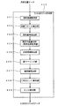
図1には、実施形態における処理の流れの概要が示されている。図1のフローチャートを実行するためのプログラムは、図2の光学データ処理装置100が備える適当なメモリ領域に格納され、光学データ処理装置100が備えるCPUによって実行される。なお、図1のフローチャートを実行するためのプログラムを外部の適当な記憶媒体に格納し、そこから光学データ処理装置100に提供される形態も可能である。この点は、明細書中で説明する数々の処理を実行するプログラムにおいても同じである。
(Outline of processing flow)
FIG. 1 shows an overview of the flow of processing in the embodiment. A program for executing the flowchart of FIG. 1 is stored in an appropriate memory area included in the optical
本実施形態では、レーザースキャナ(地上据え置き型レーザースキャナ:Terrestrial Laser Scanner(TSL)))により取得した高密度な点群位置データをまず取得する。また、それとは別に、レーザースキャナから得た点群位置データでオクルージョンとなる部分や補足したい部分をデジタルカメラによりステレオ撮影し、ステレオ写真画像の画像データを得る。この際、点群位置データが得られている部分とステレオ撮影した部分が一部重なり、この重なった部分に複数の垂直エッジ(垂直方向に延在した三次元エッジ)が含まれるようにする。そして、点群位置データおよびステレオ写真画像の画像データの双方から、三次元エッジを抽出し、それぞれの三次元モデルを作成する。次に、2つの三次元モデル間のマッチング(対応関係)を求め、両三次元モデルのデータを統合する。こうして、レーザースキャナから得た点群位置データでオクルージョンとなっている部分が補われた三次元モデルが構築される。 In this embodiment, high-density point cloud position data acquired by a laser scanner (Terrestrial Laser Scanner (TSL)) is first acquired. Separately, the point cloud position data obtained from the laser scanner uses the digital camera to take a stereo image of the occluded part or the part to be supplemented to obtain image data of a stereo photographic image. At this time, a part where the point cloud position data is obtained and a part obtained by stereo shooting partially overlap, and the overlapping part includes a plurality of vertical edges (three-dimensional edges extending in the vertical direction). Then, a 3D edge is extracted from both the point cloud position data and the image data of the stereo photographic image, and each 3D model is created. Next, matching (correspondence) between two three-dimensional models is obtained, and data of both three-dimensional models are integrated. In this way, a three-dimensional model is constructed in which the occluded portion is supplemented with the point cloud position data obtained from the laser scanner.
以下、図1を参照して処理の概要を簡単に説明する。まず、レーザースキャナを用いて測定対象物の点群位置データを取得する(ステップS100)。次いで、ステップS100で得た点群位置データに基づき、ラベリング手法による当該測定対象物の三次元モデルの作成を行う(ステップS200)。ラベリング手法による当該測定対象物の三次元モデルの作成技術については、例えばWO2011/162388号広報に記載されている技術を利用することができる。ステップS200の詳細については後述する。 Hereinafter, the outline of the processing will be briefly described with reference to FIG. First, point cloud position data of a measurement object is acquired using a laser scanner (step S100). Next, based on the point cloud position data obtained in step S100, a three-dimensional model of the measurement object is created by a labeling method (step S200). As a technique for creating a three-dimensional model of the object to be measured by a labeling technique, for example, a technique described in the publicity of WO2011 / 162388 can be used. Details of step S200 will be described later.
他方で、ステップS100で取得した点群位置データでオクルージョンとなる部分(あるいはデータを補足したい部分)をデジタルカメラでステレオ撮影する(ステップS300)。この撮影は、単眼のデジタルカメラを用いて異なる2視点からの撮影行う手法であってもよいし、専用のステレオ撮影用のデジタルカメラを用いてよい。ステレオ写真画像の画像データを得たら、それに基づき拡張TIN−LSM法により、三次元モデルの作成を行う(ステップS400)。ステップS400における拡張TIN−LSM法の詳細については後述する。 On the other hand, a portion of the point cloud position data acquired in step S100 that is occluded (or a portion for which data is desired to be captured) is photographed in stereo with a digital camera (step S300). This photographing may be a technique of photographing from two different viewpoints using a monocular digital camera, or a dedicated stereo photographing digital camera may be used. When the image data of the stereo photographic image is obtained, a three-dimensional model is created by the extended TIN-LSM method based on the image data (step S400). Details of the extended TIN-LSM method in step S400 will be described later.
次に、レーザースキャナから得た点群位置データに基づく三次元モデルとデジタルカメラで撮影したステレオ写真画像から得た三次元モデルとを統合する処理を行う。まず、レーザースキャナ由来の三次元モデルと撮影画像由来の三次元モデルのそれぞれから、マンハッタンワールド仮説に基づく法線ベクトルの抽出を行う(ステップS500)。マンハッタンワールド仮説というのは、人工構造物には互いに直交する支配的な3軸が存在し、建造物を構成する面は、それらと垂直または平行に配置しているという仮設である。ステップS500の処理により、2つの三次元モデルの方向が求まる。ステップS500の処理の詳細は後述する。 Next, a process of integrating the three-dimensional model based on the point cloud position data obtained from the laser scanner and the three-dimensional model obtained from the stereo photograph image taken by the digital camera is performed. First, normal vectors based on the Manhattan World Hypothesis are extracted from each of the three-dimensional model derived from the laser scanner and the three-dimensional model derived from the photographed image (step S500). The Manhattan World Hypothesis is a hypothesis that man-made structures have three dominant axes orthogonal to each other, and the surfaces constituting the building are arranged vertically or parallel to them. By the process of step S500, the directions of the two three-dimensional models are obtained. Details of the processing in step S500 will be described later.
次に、ステップS500で求めた法線ベクトルの向きを合わせることで、2つの三次元モデルの向きを合わせる(ステップS600)。この処理は、一方または双方の三次元モデルを回転させ、両三次元モデルの3軸の方向を合わせる。 Next, the orientations of the two three-dimensional models are matched by matching the orientations of the normal vectors obtained in step S500 (step S600). In this process, one or both three-dimensional models are rotated and the directions of the three axes of both three-dimensional models are aligned.
次に、2つの三次元モデルのそれぞれを構成する三次元エッジの位置合わせを行い、両三次元モデルの対応関係を求め(ステップS700)、更にステップS700で求めた対応関係に基づき、レーザースキャナから得た点群位置データに基づく三次元モデルとカメラで撮影した画像から得た三次元モデルとを統合し、統合された三次元モデルを得る(ステップS800)。 Next, the alignment of the three-dimensional edges constituting each of the two three-dimensional models is performed to obtain the correspondence between both the three-dimensional models (step S700). Further, based on the correspondence obtained in step S700, the laser scanner The three-dimensional model based on the obtained point cloud position data and the three-dimensional model obtained from the image captured by the camera are integrated to obtain an integrated three-dimensional model (step S800).
(光学データ処理装置の概要)
以下、図1の処理を実行する光学データ処理装置の一例を説明する。図2には、光学データ処理装置100が示されている。光学データ処理装置100は、パーソナルコンピュータ内においてソフトウェア的に構成されている。すなわち、本発明を利用した処理を行う専用のソフトウェアがインストールされたパーソナルコンピュータが図1の光学データ処理装置100として機能する。このプログラムは、パーソナルコンピュータ中にインストールされている状態に限定されず、サーバや適当な記録媒体に記録しておき、そこから提供される形態であってもよい。
(Outline of optical data processor)
Hereinafter, an example of an optical data processing apparatus that executes the processing of FIG. 1 will be described. FIG. 2 shows an optical
利用されるパーソナルコンピュータは、キーボートやタッチパネルディスプレイ等の入力部、液晶ディスプレイ等の表示部、入力部と表示部を統合したユーザインターフェースであるGUI(グラフィカル・ユーザ・インターフェース)機能部、CPUおよびその他専用の演算デバイス、半導体メモリ、ハードディスク記憶部、光ディスク等の記憶媒体との間で情報のやり取りを行えるディスク記憶装置駆動部、USBメモリ等の携帯型記憶媒体との間で情報のやり取りを行えるインターフェース部、無線通信や有線通信を行う通信インターフェース部を必要に応じて備えている。なお、パーソナルコンピュータの形態は限定されず、ノート型、携帯型、卓上型等から適宜選択することができる。また、汎用のパーソナルコンピュータを利用する以外に、ASIC(Application Specific Integrated Circuit)や、FPGA(Field Programmable Gate Array)などのPLD(Programmable
Logic Device)等を用いて構成した専用のハードウェアによって光学データ処理装置100の一部または全部を構成することも可能である。
The personal computer used is an input unit such as a keyboard or a touch panel display, a display unit such as a liquid crystal display, a GUI (graphical user interface) function unit that is a user interface integrating the input unit and the display unit, a CPU, and other dedicated units. Interface device that can exchange information with a portable storage medium such as a USB storage device, a disk storage device drive unit that can exchange information with a storage device such as a computing device, a semiconductor memory, a hard disk storage unit, and an optical disk A communication interface unit for performing wireless communication or wired communication is provided as necessary. The form of the personal computer is not limited, and can be appropriately selected from a notebook type, a portable type, a desktop type, and the like. In addition to using a general-purpose personal computer, PLD (Programmable Gate Array) such as Application Specific Integrated Circuit (ASIC) or Field Programmable Gate Array (FPGA)
Part or all of the optical
光学データ処理装置100には、レーザースキャナ200とデジタルカメラ300が接続あるいは接続可能とされている。レーザースキャナ200は、測定対象物にレーザー光を走査して照射し、その反射光を検出する。レーザースキャナ200の設置位置は予め正確に求められており、照射レーザー光の照射方向とレーザ光の飛翔時間から算出される照射点までの距離に基づき、照射レーザ光の照射点の三次元位置の算出が行われる。この処理を、少しずつ位置をずらしながら走査して行うことで、多数(数万点〜数億点)の照射点の三次元座標が点群位置データとして取得される。この点群位置データが光学データ処理装置100に入力される。デジタルカメラ300は、三次元写真測量(立体写真測量)に用いられるステレオ画像を撮影し、その画像データが光学データ処理装置100に入力される。ここでは、1台のデジタルカメラを用い、異なる2つの視点から撮影を行うことで、ステレオ写真画像の撮影を行う場合を説明する。勿論、光学系を2つ備えた立体写真撮影用のカメラを用いてステレオ写真画像の撮影を行なう構成も可能である。
A
光学データ処理装置100は、点群位置データ処理部400、写真画像データ処理部500、法線ベクトル抽出部600、三次元モデル向き調整部700、三次元エッジ位置合わせ部800、三次元モデル統合部900を備えている。点群位置データ処理部400は、レーザースキャナ200から得られる点群位置データに基づき、測定対象物の三次元モデルを作成する。点群位置データ処理部400は、点群位置データ取得部410と三次元モデル作成部420を備えている。点群位置データ取得部410は、レーザースキャナ200から送られてくる測定対象物の点群位置データを取得する(図1のステップS100)。三次元モデル作成部420は、点群位置データ取得部410が取得した点群位置データに基づき、レーザースキャナ200が計測した測定対象物の三次元モデルを作成する(図1のステップS200)。三次元モデル作成部420の詳細については後述する。
The optical
写真画像データ処理部500は、デジタルカメラ300が撮影したステレオ写真画像の画像データに基づき、測定対象物の三次元モデルを作成する。ステレオ写真画像は、視点を左右にずらした左写真画像と右写真画像とで構成される。外部標定要素を用いてステレオ写真画像から、左右の偏位修正画像(左右の写真画像のエピポーララインを同一水平線上に再配置した画像)を作成し、この左右の偏位修正画像を左右に並べ、偏向眼鏡等を用いて左目で左偏位修正画像を選択的に視認し、右目で右偏位修正画像を選択的に視認することで、立体視を行うことができる。
The photo image data processing unit 500 creates a three-dimensional model of the measurement object based on the image data of the stereo photo image taken by the
写真画像データ処理部500は、写真画像データ取得部510と三次元モデル作成部520を備えている。写真画像データ取得部510は、デジタルカメラ300から送られてくる測定対象物のステレオ写真画像の画像データを取得する処理を行う(図1のステップS300)。三次元モデル作成部520は、写真画像データ取得部510が取得したステレオ写真画像の画像データに基づき、デジタルカメラ300が撮影した測定対象物の三次元モデルを作成する(図1のステップS400)。三次元モデル作成部520の詳細については後述する。
The photographic image data processing unit 500 includes a photographic image data acquisition unit 510 and a 3D model creation unit 520. The photographic image data acquisition unit 510 performs processing for acquiring image data of a stereo photographic image of the measurement object sent from the digital camera 300 (step S300 in FIG. 1). The three-dimensional model creation unit 520 creates a three-dimensional model of the measurement object photographed by the
法線ベクトル抽出部600は、三次元モデル作成部420および520が作成した2つの三次元モデルを対象に、マンハッタンワールド仮説に基づく3方向の法線ベクトルの抽出(つまり直行するXYZ軸の抽出)を行う。三次元モデル向き調整部700は、法線ベクトル抽出部600が抽出した各三次元モデルの法線ベクトルに基づき、三次元モデル作成部420および520が作成した2つの三次元モデルの一方または両方の向きを調整し、その向きを合わせる処理を行う。三次元エッジ位置合わせ部800は、三次元モデル向き調整部700により向きを合わせる調整が行われた2つの三次元モデル間において、対応する三次元エッジを求める処理を行う。三次元モデル統合部900は、レーザースキャナ200が計測した点群位置データに基づく三次元モデルと、デジタルカメラ300が撮影したステレオ画像の画像データに基づく三次元モデルとを統合した三次元モデルを作成する。
The normal
レーザースキャナ200が計測した点群位置データに基づく三次元モデルに統合される撮影画像に基づく三次元モデルは、1つに限定されず、複数であってもよい。例えば、レーザースキャナ200が計測した点群位置データに基づく三次元モデルにオクルージョンが複数あり、この複数のオクルージョンがデジタルカメラ300による1回のステレオ撮影では撮影できない場合があるとする。この場合、複数のオクルージョンを異なる視点から個別にステレオ写真撮影し、複数の視点毎のステレオ写真画像の画像データを写真画像データ処理部500で処理し、複数の視点毎にステレオ写真画像由来の三次元モデルを作成する。そして、点群位置データ由来の三次元モデルとステレオ写真画像由来の三次元モデルとの統合を行うことで、第1次統合三次元モデルを作成し、次いで第1次統合三次元モデルと次のステレオ写真画像由来の三次元モデルとの統合を行うことで、第2次統合三次元モデルを作成し、といった処理を繰り返す。こうすることで、次々とオクルージョンを解消してゆき、三次元モデルの完成度を高めることができる。
The three-dimensional model based on the photographed image integrated with the three-dimensional model based on the point cloud position data measured by the
(点群位置データからの三次元モデルの作成)
図2の三次元モデル作成部420の詳細、およびその動作(図1のステップS200)の詳細について説明する。図3には、三次元モデル作成部420のブロック図が示されている。三次元モデル形成部420は、局所領域を取得する局所領域取得部421、局所領域の法線ベクトルを算出する法線ベクトル算出部422、局所領域の局所曲率を算出する局所曲率算出部423、局所領域にフィッティングする局所平面を算出する局所平面算出部424、非面領域除去部425、面ラベリング部426、輪郭線算出部427、二次元エッジ算出部428、エッジ統合部429を備えている。
(Create a 3D model from point cloud position data)
Details of the three-dimensional model creation unit 420 in FIG. 2 and details of its operation (step S200 in FIG. 1) will be described. FIG. 3 shows a block diagram of the three-dimensional model creation unit 420. The three-dimensional model formation unit 420 includes a local region acquisition unit 421 that acquires a local region, a normal vector calculation unit 422 that calculates a normal vector of the local region, a local curvature calculation unit 423 that calculates a local curvature of the local region, A local plane calculation unit 424 that calculates a local plane to be fitted to a region, a non-surface region removal unit 425, a surface labeling unit 426, a contour calculation unit 427, a two-dimensional edge calculation unit 428, and an edge integration unit 429 are provided.
局所領域取得部421は、点群位置データに基づき、注目点を中心とした一辺が3〜7画素程度の正方領域(格子状の領域)を局所領域として取得する。法線ベクトル算出部422は、局所領域取得部421が取得した上記の局所領域における各点の法線ベクトルの算出を行う。この法線ベクトルを算出する処理では、局所領域における点群位置データに着目し、各点の法線ベクトルを算出する。この処理は、全ての点群位置データを対象として行われる。すなわち、点群位置データが無数の局所領域に区分けされ、各局所領域において各点の法線ベクトルの算出が行われる。 Based on the point cloud position data, the local area acquisition unit 421 acquires a square area (grid-like area) having a side of about 3 to 7 pixels around the target point as a local area. The normal vector calculation unit 422 calculates a normal vector of each point in the local region acquired by the local region acquisition unit 421. In the process of calculating the normal vector, attention is paid to the point cloud position data in the local region, and the normal vector of each point is calculated. This process is performed for all point cloud position data. That is, the point cloud position data is divided into an infinite number of local regions, and the normal vector of each point is calculated in each local region.
局所曲率算出部423は、上述した局所領域内の法線ベクトルのバラツキ(局所曲率)を算出する。ここでは、着目している局所領域において、各法線ベクトルの3軸成分の強度値(NVx, NVy, NVz)の平均(mNVx,mNVy,mNVz)を求め、さらに標準偏差(StdNVx,StdNVy,StdNVz)を求める。次に、標準偏差の二乗和の平方根を局所曲率(Local Curveture:crv)として算出する(数1)。 The local curvature calculation unit 423 calculates variation (local curvature) of normal vectors in the above-described local region. Here, the average (mNVx, mNVy, mNVz) of the intensity values (NVx, NVy, NVz) of the three-axis components of each normal vector is obtained in the local region of interest, and the standard deviation (StdNVx, StdNVy, StdNVz) ) Next, the square root of the square sum of the standard deviation is calculated as a local curvature (crv) (Equation 1).
![]()
![]()
局所平面算出部424は、局所領域にフィッティング(近似)する局所平面(局所空間)を求める。この処理では、着目している局所領域の各点の三次元座標から局所平面の方程式を求める。局所平面は、着目している局所領域にフィッティングさせた平面である。ここでは、最小二乗法を用いて、当該局所領域にフィッティングする局所平面の面の方程式を算出する。具体的には、複数の異なる平面方程式を求め、更にそれらを比較し、当該局所領域にフィッティングする局所平面の面の方程式を算出する。仮に、着目している局所領域が平面であれば、局所平面と局所領域とは一致する。 The local plane calculation unit 424 obtains a local plane (local space) that is fitted (approximated) to the local region. In this process, an equation of the local plane is obtained from the three-dimensional coordinates of each point in the local region of interest. The local plane is a plane that is fitted to the local region of interest. Here, the equation of the surface of the local plane to be fitted to the local region is calculated using the least square method. Specifically, a plurality of different plane equations are obtained, compared with each other, and a surface equation of the local plane to be fitted to the local region is calculated. If the local region of interest is a plane, the local plane and the local region match.
以上の処理を、局所領域を順次ずらしながら、全ての点群位置データが対象となるように繰り返し行い、各局所領域における法線ベクトル、局所平面、局所曲率を得る。 The above processing is repeated so that all point cloud position data is targeted while sequentially shifting the local area, and the normal vector, local plane, and local curvature in each local area are obtained.
非面領域除去部425は、上で求めた各局所領域における法線ベクトル、局所平面、局所曲率に基づいて、非面領域の点を除去する処理を行う。すなわち、面(平面および曲面)を抽出するために、予め面でないと判断できる部分(非面領域)を除去する。なお、非面領域とは、平面でも曲面でもない領域であるが、下記の(1)〜(3)の閾値によっては曲率の高い曲面を含む場合がある。 The non-surface area removing unit 425 performs processing for removing points in the non-surface area based on the normal vector, local plane, and local curvature in each local area obtained above. That is, in order to extract a surface (a plane and a curved surface), a portion (non-surface region) that can be determined as not a surface in advance is removed. The non-surface region is a region that is neither a plane nor a curved surface, but may include a curved surface with a high curvature depending on the following threshold values (1) to (3).
非面領域除去の処理は、以下に示す3つの方法のうち、少なくとも一つを用いて行うことができる。ここでは、下記の(1)〜(3)の方法による判定を上述した局所領域の全てに対して行い、1以上の方法において非面領域と判定された局所領域を、非面領域を構成する局所領域として抽出する。そして、抽出された非面領域を構成する点に係る点群位置データを除去する。 The non-surface area removal process can be performed using at least one of the following three methods. Here, the determination by the following methods (1) to (3) is performed for all the local regions described above, and the local region determined as the non-surface region by one or more methods is configured as the non-surface region. Extract as a local region. Then, the point cloud position data relating to the points constituting the extracted non-surface area is removed.
(1)局所曲率の高い部分:上述した局所曲率を予め設定しておいた閾値と比較し、閾値を超える局所曲率の局所領域を非面領域と判定する。局所曲率は、注目点とその周辺点における法線ベクトルのバラツキを表しているので、面(平面および曲率の小さい曲面)ではその値が小さく、面以外(非面)ではその値は大きくなる。したがって、予め決めた閾値よりも局所曲率が大きければ、当該局所領域を非面領域と判定する。 (1) A portion having a high local curvature: The above-described local curvature is compared with a preset threshold value, and a local region having a local curvature exceeding the threshold value is determined as a non-surface region. Since the local curvature represents the variation of the normal vector at the point of interest and its peripheral points, the value is small for a surface (a flat surface and a curved surface with a small curvature), and the value is large for a surface other than a surface (non-surface). Therefore, if the local curvature is larger than a predetermined threshold, the local region is determined as a non-surface region.
(2)局所平面のフィッティング精度:局所領域の各点と対応する局所平面との距離を計算し、これらの距離の平均が予め設定した閾値よりも大きい場合、当該局所領域を非面領域と判定する。すなわち、局所領域が平面から乖離した状態であると、その程度が激しい程、当該局所領域の各点と対応する局所平面との距離は大きくなる。このことを利用して当該局所領域の非面の程度が判定される。 (2) Local plane fitting accuracy: the distance between each point of the local area and the corresponding local plane is calculated, and if the average of these distances is greater than a preset threshold, the local area is determined to be a non-surface area To do. That is, when the local area is in a state of being deviated from the plane, the distance between the local plane corresponding to each point of the local area increases as the degree becomes more severe. Using this fact, the degree of non-surface of the local region is determined.
(3)共平面性のチェック:ここでは、隣接する局所領域において、対応する局所平面同士の向きを比較する。この局所平面の向きの違いが閾値を超えている場合、比較の対象となった局所領域が非面領域に属していると判定する。具体的には、対象となる2つの局所領域のそれぞれにフィッティングする2つの局所平面の法線ベクトルと、その中心点間を結ぶベクトルとの内積が0であれば、両局所平面が同一平面上に存在すると判定される。また、上記内積が大きくなる程、2つの局所平面が同一面上にない程度がより顕著であると判定される。 (3) Coplanarity check: Here, the directions of corresponding local planes are compared in adjacent local regions. If the difference in orientation of the local planes exceeds the threshold value, it is determined that the local area to be compared belongs to the non-plane area. Specifically, if the inner product of the normal vector of the two local planes fitted to each of the two target local regions and the vector connecting the center points is 0, both local planes are on the same plane. Is determined to exist. Moreover, it is determined that the extent that the two local planes are not on the same plane is more remarkable as the inner product becomes larger.
上記の(1)〜(3)の方法による判定において、1以上の方法において非面領域と判定された局所領域を、非面領域を構成する局所領域として抽出する。そして、この抽出された局所領域を構成する点に係る点群位置データを算出対象としている点群位置データから除去する。以上のようにして、非面領域の除去が行われる。こうして、点群位置データの中から非面領域の点群位置データが非面領域除去部425において除去される。なお、除去された点群位置データは、後の処理で利用する可能性があるので、適当な記憶領域に格納するなり、除去されなかった点群位置データと識別できる状態とするなどして、後で利用できる状態にしておく。 In the determination by the above methods (1) to (3), a local region determined as a non-surface region by one or more methods is extracted as a local region constituting the non-surface region. Then, the point cloud position data relating to the points constituting the extracted local region is removed from the point cloud position data to be calculated. The non-surface area is removed as described above. In this way, the point group position data of the non-surface area is removed from the point group position data by the non-surface area removal unit 425. Since the removed point cloud position data may be used in later processing, it can be stored in an appropriate storage area, or can be identified from the point cloud position data that has not been removed. Keep it available later.
次に面ラベリング部426の機能について説明する。面ラベリング部426は、非面領域除去部425において非面領域の点群位置データが除去された点群位置データに対して、法線ベクトルの連続性に基づいて面ラベリングを行う。具体的には、特定の注目点と隣接点の法線ベクトルの角度差が予め決めた閾値以下なら、それらの点に同一ラベルを貼る。この作業を繰り返すことで、連続する平面、連続する緩やかな曲面に同一ラベルが貼られ、それらを一つの面として識別可能となる。また、面ラベリングの後、法線ベクトルの角度差や法線ベクトルの3軸成分の標準偏差を用いて、ラベル(面)が平面であるか、または曲率の小さい曲面であるかを判定し、その旨を識別する識別データを各ラベルに関連付ける。 Next, the function of the surface labeling unit 426 will be described. The surface labeling unit 426 performs surface labeling on the point cloud position data from which the non-surface region point cloud position data has been removed by the non-surface region removal unit 425 based on the continuity of normal vectors. Specifically, if the angle difference between the normal vector of a specific point of interest and an adjacent point is less than a predetermined threshold, the same label is attached to those points. By repeating this operation, the same label is attached to a continuous flat surface and a continuous gentle curved surface, and these can be identified as one surface. Further, after the surface labeling, it is determined whether the label (surface) is a plane or a curved surface with a small curvature by using the angle difference between the normal vectors and the standard deviation of the three-axis components of the normal vectors. Identification data for identifying the fact is associated with each label.
続いて、面積の小さいラベル(面)をノイズとして除去する。なお、このノイズ除去は、面ラベリングの処理と同時に行ってもよい。この場合、面ラベリングを行いながら、同一ラベルの点数(ラベルを構成する点の数)を数え、所定以下の点の数であるラベルを取り消す処理を行う。次に、この時点でラベルが無い点に対して、最近傍面(最も近い面)と同一のラベルを付与していく。これにより、既にラベリングされた面の拡張を行う。 Subsequently, the label (surface) having a small area is removed as noise. This noise removal may be performed simultaneously with the surface labeling process. In this case, while performing surface labeling, the number of points of the same label (the number of points constituting the label) is counted, and a process of canceling the label having the number of points equal to or less than a predetermined value is performed. Next, the same label as the nearest surface (closest surface) is given to the point having no label at this time. As a result, the already labeled surface is expanded.
すなわち、ラベルの付いた面の方程式を求め、当該面とラベルが無い点との距離を求める。ラベルが無い点の周辺に複数のラベル(面)がある場合には、その距離が最も短いラベルを選択する。そして、依然としてラベルが無い点が残存している場合には、非面領域除去、ノイズ除去、およびラベル拡張における各閾値を変更し、再度関連する処理を行う。例えば、非面領域除去において、局所曲率の閾値を上げることで、非面として抽出する点の数が少なくなるようにする。または、ラベル拡張において、ラベルの無い点と最近傍面との距離の閾値を上げることで、ラベルの無い点に対してより多くのラベルを付与するようにする。 That is, the equation of the surface with the label is obtained, and the distance between the surface and the point without the label is obtained. If there are a plurality of labels (surfaces) around a point where there is no label, the label with the shortest distance is selected. If there is still a point with no label, the threshold values for non-surface area removal, noise removal, and label expansion are changed, and related processing is performed again. For example, in non-surface area removal, the number of points to be extracted as non-surface is reduced by increasing the threshold value of local curvature. Alternatively, in label expansion, by increasing the threshold of the distance between a point without a label and the nearest surface, more labels are given to the point without a label.
次に、ラベルが異なる面であっても同一面である場合にラベルを統合する。この場合、連続しない面であっても、位置または向きが等しい面同士に同じラベルを付ける。具体的には、各面の法線ベクトルの位置および向きを比較することで、連続しない同一面を抽出し、いずれかの面のラベルに統一する。以上が面ラベリング部426の機能である。この面ラベリング部426の機能によれば、扱うデータ量を圧縮できるので、点群位置データの処理を高速化できる。また必要なメモリ量を節約できる。また、測定中に紛れ込んだ通行人や通過した車両の点群位置データをノイズとして除去することができる。 Next, even if the labels are different surfaces, the labels are integrated when they are the same surface. In this case, even if the surfaces are not continuous, the same label is attached to the surfaces having the same position or orientation. Specifically, by comparing the position and orientation of the normal vector of each surface, the same non-continuous surface is extracted and unified to the label of any surface. The above is the function of the surface labeling unit 426. According to the function of the surface labeling unit 426, the amount of data to be handled can be compressed, so that the processing of the point cloud position data can be accelerated. In addition, the required amount of memory can be saved. Further, it is possible to remove the point cloud position data of a passerby or a vehicle that has passed through during measurement as noise.
輪郭線算出部427は、隣接する面の点群位置データに基づき、輪郭線を算出(推定)する。以下、具体的な算出方法について説明する。輪郭線算出部427は、間に非面領域を挟む隣接する面同士の交線を求め、それを輪郭線とする処理を行う。輪郭線を算出する処理の他の方法としては、隣接する面の間の非面領域に局所平面をフィッティングさせ、この局所平面を複数繋ぐことで、非面領域を複数の局所平面によって近似する方法を採用することもできる。これは、複数の局所平面により構成される多面体で非面領域を近似したものと捉えることができる。この場合、隣接する面から局所平面をつないでゆき、最後に隣接した局所平面同士の交線を輪郭線として算出する。輪郭線が算出されることで、測定対象物の輪郭の画像が明確となる。 The contour calculation unit 427 calculates (estimates) the contour based on the point cloud position data of the adjacent surfaces. Hereinafter, a specific calculation method will be described. The contour line calculation unit 427 obtains an intersection line between adjacent surfaces sandwiching a non-surface region therebetween, and performs a process of using this as a contour line. As another method of calculating the contour line, a method of approximating a non-surface region by a plurality of local planes by fitting a local plane to a non-surface region between adjacent surfaces and connecting a plurality of local planes. Can also be adopted. This can be regarded as an approximation of a non-planar region by a polyhedron composed of a plurality of local planes. In this case, the local planes are connected from the adjacent surfaces, and the line of intersection between the adjacent local planes is calculated as the contour line. By calculating the contour line, the contour image of the measurement object becomes clear.
次に、二次元エッジ算出部428について説明する。以下、二次元エッジ算出部428で行われる処理の一例を説明する。まず、対象物からの反射光の強度分布に基づいて、ラプラシアン、プリューウィット、ソーベル、キャニーなどの公知のエッジ抽出オペレータを用いて、セグメント化(区分け)された面に対応する二次元画像の領域内からエッジを抽出する。すなわち、エッジは、面内の濃淡の違いにより認識されるので、この濃淡の違いを反射光の強度の情報から抽出し、その抽出条件に閾値を設けることで、濃淡の境目をエッジとして抽出する。次に、抽出されたエッジを構成する点の三次元座標の高さ(z値)と、その近傍の輪郭線を構成する点の三次元座標の高さ(z値)とを比較し、この差が所定の閾値以内の場合には、当該エッジを二次元エッジとして抽出する。すなわち、二次元画像上で抽出されたエッジを構成する点が、セグメント化された面上にあるか否かを判定し、面上にあると判定された場合にそれを二次元エッジとする。 Next, the two-dimensional edge calculation unit 428 will be described. Hereinafter, an example of processing performed by the two-dimensional edge calculation unit 428 will be described. First, based on the intensity distribution of the reflected light from the object, a region of a two-dimensional image corresponding to a segmented (segmented) surface using a known edge extraction operator such as Laplacian, Pleuwit, Sobel, Canny Extract edges from within. That is, since the edge is recognized by the difference in shading in the plane, the difference in shading is extracted from the information on the intensity of the reflected light, and by setting a threshold in the extraction condition, the border between the shading is extracted as an edge. . Next, the height (z value) of the three-dimensional coordinates of the points constituting the extracted edge is compared with the height (z value) of the three-dimensional coordinates of the points constituting the neighboring contour line. If the difference is within a predetermined threshold, the edge is extracted as a two-dimensional edge. That is, it is determined whether or not a point constituting the edge extracted on the two-dimensional image is on the segmented surface, and if it is determined that the point is on the surface, it is set as the two-dimensional edge.
エッジ統合部429は、輪郭線算出部427が算出した輪郭線と二次元エッジ算出部428が算出した二次元エッジとを統合する。これにより、点群位置データに基づく三次元エッジの抽出が行われる。このエッジの抽出により、測定対象物を視認する際における測定対象物の外観を構成する線が三次元エッジとして抽出される。この三次元エッジにより測定対象物の外観が形作られ、三次元モデルが形成される。 The edge integration unit 429 integrates the contour line calculated by the contour line calculation unit 427 and the two-dimensional edge calculated by the two-dimensional edge calculation unit 428. Thereby, extraction of the three-dimensional edge based on the point cloud position data is performed. By this edge extraction, a line constituting the appearance of the measurement object when the measurement object is visually recognized is extracted as a three-dimensional edge. The appearance of the measurement object is formed by the three-dimensional edge, and a three-dimensional model is formed.
(写真画像データからの三次元モデルの作成)
写真画像データ処理部500の三次元モデル作成部520の詳細、およびその動作(図1のステップS400)について説明する。以下において、1台のカメラを用い、位置を変えての撮影を行なうことで、左写真画像と右写真画像を得る場合の例を説明する。勿論、左右2台のカメラを用意して、左写真画像と右写真画像を同時に撮影する構成も可能である。
(Create a 3D model from photographic image data)
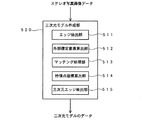
Details of the three-dimensional model creation unit 520 of the photographic image data processing unit 500 and its operation (step S400 in FIG. 1) will be described. In the following, an example will be described in which a left camera image and a right camera image are obtained by performing shooting at different positions using a single camera. Of course, it is possible to prepare two left and right cameras and simultaneously shoot a left photographic image and a right photographic image.
図4には、三次元モデル作成部520(図2参照)のブロック図が示されている。三次元モデル作成部520には、デジタルカメラ300からステレオ画像を構成する左写真画像の画像データと右写真画像の画像データとが入力される。三次元モデル作成部520は、エッジ抽出部511、外部標定要素算出部512、マッチング処理部513、特徴点座標算出部514、三次元エッジ抽出部515を備えている。
FIG. 4 is a block diagram of the three-dimensional model creation unit 520 (see FIG. 2). The three-dimensional model creation unit 520 receives image data of a left photographic image and image data of a right photographic image that form a stereo image from the
(エッジ抽出部)
エッジ抽出部511は、左写真画像および右写真画像のそれぞれから測定対象物のエッジを抽出する。ここで、左写真画像および右写真画像は平面画像であるので、抽出の対象となるエッジは、画像中の測定対象物を構成する2次元の輪郭線の部分となる。エッジ抽出部511におけるエッジの抽出は、以下のようにして行われる。まず、Sobelフィルタを用い、エッジ強度の向きを用いたNMS(非最大値抑制)で細線化したのち、エッジ強度により閾値処理を行う。ここで、x軸方向の強度の微分をfx、y軸方向の強度の微分をfyとすると、数2のよりエッジ強度Iが表される。
(Edge extraction unit)
The edge extraction unit 511 extracts the edge of the measurement object from each of the left photographic image and the right photographic image. Here, since the left photographic image and the right photographic image are planar images, the edge to be extracted becomes a part of a two-dimensional contour line constituting the measurement object in the image. Edge extraction in the edge extraction unit 511 is performed as follows. First, after thinning by NMS (non-maximum value suppression) using the direction of edge strength using a Sobel filter, threshold processing is performed by edge strength. Here, when differentiated f x of the intensity of the x-axis direction, the derivative of the intensity of the y-axis direction is f y, the

そして、左右の写真画像中における直線のコーナー(変曲点)の検出を行い、コーナーを除去した残りの線分の端点を直線として抽出する。図5には、エッジを抽出する原理が示されている。この場合、注目画素(x1,y1)から2画素前後離れた連結画素(xo,yo)、(x2,y2)による2つのベクトルaとベクトルb間の狭角値θ(下記数3参照)が特定の閾値(この場合は、30°)以上であるか否かを判定し、当該狭角値が当該閾値以上である場合に、ベクトルの向きが変わる端点の部分をコーナー点として抽出する。 Then, straight line corners (inflection points) in the left and right photographic images are detected, and the end points of the remaining line segments from which the corners are removed are extracted as straight lines. FIG. 5 shows the principle of extracting an edge. In this case, a narrow angle value θ ( 2 ) between the two vectors a and b by the connected pixels (x o , y o ) and (x 2 , y 2 ) that are separated by about two pixels from the target pixel (x 1, y 1 ). It is determined whether or not the following equation (3) is equal to or greater than a specific threshold value (in this case, 30 °). Extract as a point.
次に、エッジとして採用して妥当かどうかの評価が行われる。この処理では、まず抽出した直線の長さLにおける各画素の強度Iの累積値を評価関数とし、この評価関数が予め決められた閾値を超えているか否かの判定がされる。この評価条件は、下記数4によって表される。
Next, it is evaluated whether it is appropriate to adopt as an edge. In this process, first, the cumulative value of the intensity I of each pixel in the extracted straight line length L is used as an evaluation function, and it is determined whether or not this evaluation function exceeds a predetermined threshold value. This evaluation condition is expressed by the following
ここで、数4の左辺が閾値であり、その値は、最大強度Iのk倍として定義されている。この閾値は、実験的に求められた値を用いる。kの値は、例えばk=5が用いられる。上記の評価をクリアした直線がエッジとして採用される。このエッジは、始点と終点(つまり両端の端点)の座標によって記述される。この方法によれば、強度の弱いノイズとなるエッジが除去され、測定対象物を特徴付けるエッジを効率よく抽出することができる。また、演算量を減らせるので、演算時間を短縮化できる。
Here, the left side of
(外部標定要素算出部)
外部標定要素算出部511は、ステレオ写真画像に基づき、相互標定法を用いて外部標定要素の算出を自動的に行なう。つまり、左右の写真画像の対応関係を演算により求め、その結果を用いて、相互標定法により左右の写真画像の撮影時におけるカメラの向きと位置(撮影対象物に対する相対的なカメラの向きと位置)の算出を行う。相互標定法は、既知点がなくとも相対的な外部標定要素が求められる方法である。処理の流れとしては、まず、左写真画像と右写真画像とにおける対応する特徴点を求める。そして、左右の写真画像で対応する特徴点から標定用の対応点を求め、この標定用の対応点を用いた相互標定法により左写真画像と右写真画像の外部標定要素を求める。
(External orientation element calculation unit)
The external orientation element calculation unit 511 automatically calculates an external orientation element using the relative orientation method based on the stereo photographic image. In other words, the correspondence between the left and right photographic images is obtained by calculation, and the results are used to determine the camera orientation and position when the left and right photographic images are taken by the relative orientation method (the camera orientation and position relative to the subject to be photographed). ) Is calculated. The relative orientation method is a method in which a relative external orientation element is obtained even if there is no known point. As a processing flow, first, corresponding feature points in the left photograph image and the right photograph image are obtained. Then, the corresponding points for orientation are obtained from the corresponding feature points in the left and right photographic images, and the external orientation elements of the left and right photographic images are obtained by the relative orientation method using the corresponding points for orientation.
以下、順を追って外部標定要素を算出する手順を説明する。最初に対応する点に関する左写真画像と右写写真画像における位置の差である視差量を推定視差量として推定する。この処理では、まずエッジ抽出部511の機能により、左右の写真画像のそれぞれから、エッジ(2次元エッジ)の抽出が行われる。このエッジの抽出には、モラベック、ラプラシアン、ソーベルなどの微分フィルタが用いられる。なお、ここで抽出されるエッジの延在方向は特に限定されない。 Hereinafter, the procedure for calculating the external orientation elements will be described in order. First, a parallax amount that is a difference in position between a left photograph image and a right photograph image regarding a corresponding point is estimated as an estimated parallax amount. In this process, first, an edge (two-dimensional edge) is extracted from each of the left and right photographic images by the function of the edge extraction unit 511. For this edge extraction, differential filters such as Moravec, Laplacian, and Sobel are used. The extending direction of the edge extracted here is not particularly limited.
次に、縮小画像を対象に、先に抽出したエッジの端点近傍をテンプレートとして、左右画像のステレオマッチングを正規化相互相関法によって行う。縮小画像を用いるのは、処理を高速化するためである。この処理により、先に抽出したエッジの端点を対象とした左右の写真画像間における対応関係の探索が行われる。ここで、左右の写真画像中でマッチングがとれた対応点(エッジの端部)の座標を(x,y)、(xe,ye)とし、(x,y)を射影変換した値点を(x’,y’)とすると、(x,y)と(x’,y’)との間の関係は、数5で表される。
Next, with the reduced image as a target, the left and right images are stereo-matched by the normalized cross-correlation method using the vicinity of the end point of the previously extracted edge as a template. The reduced image is used for speeding up the processing. By this processing, a search for correspondence between the left and right photographic images targeting the end points of the previously extracted edges is performed. Here, (x, y), (x e , y e ) are the coordinates of the corresponding points (edge edges) that are matched in the left and right photographic images, and (x, y) is a projective transformation value point When (x ′, y ′) is (x ′, y ′), the relationship between (x, y) and (x ′, y ′) is expressed by
数5の射影変換のパラメータb1〜b8は、8点法にRANSAC処理を用いて算出する。この際、「撮影した画像中における建築物は平面と垂直成分のエッジから構成されている」という仮定に基づいて未知のパラメータb1〜b8の推定が行われる。RANSAC処理は、以下の手順により、未知のパラメータを推定する手法である。(1)総データ個数がU個あるデータから、ランダムでn個のデータを取り出す。(2)取り出したn個のデータから、パラメータを求める(取り出すデータの個数は、求めるべきパラメータの数に比例する)。(3)求めたパラメータを、総データ点数から取り出したn個のデータを除いたものに式を当てはめ、観測されたデータと(2)で求めたパラメータの誤差を計算する。(4)誤差が許容範囲内であれば、パラメータに対して投票を行う。(5)〜(4)を繰り返し、投票数が一番多かったパラメータを仮パラメータとして仮採用する。(6)仮パラメータを使ってすべてのデータに再度式を適用し、誤差が許容範囲内のものを抽出する。(7)抽出したデータを元に、再度パラメータを求める。(8)求まったパラメータを、このデータのもっともらしいパラメータとする。
The projective transformation parameters b 1 to b 8 in
推定視差量Pは、Gibbs分布を表す式である数5により表される。ここで、残差J(Δp/Δq)が小さい程、特徴点として正しい可能性が高く、P=1に近いものを上位から複数選び視差推定量とする。また、このときの係数をs=0.05と設定する。
The estimated parallax amount P is expressed by
視差推定量Pを求めたら、左右の斜視画像間で対応関係が判明しているエッジの端点に着目し、その中から、垂直エッジ(垂直方向に延在しているエッジ)を構成している端点を選択し、この端点の部分における視差推定量Pを取得する。こうすることで、横向きの変形に強く、且つ、エピポーラライン上のマッチングを正確に行うことができる。 When the parallax estimation amount P is obtained, attention is paid to the end points of the edges whose correspondence is known between the left and right perspective images, and the vertical edges (edges extending in the vertical direction) are formed from the end points. An end point is selected, and a parallax estimation amount P at the end point portion is acquired. By doing so, it is resistant to lateral deformation and matching on the epipolar line can be performed accurately.
次に、左右の写真画像の等倍画像を対象に特徴点の再抽出を行う。ここで改めて抽出された特徴点の中から標定用の対応点が求められる。この特徴点の抽出には、モラベック、ラプラシアン、ソーベルなどの微分フィルタが用いられる。 Next, the feature points are re-extracted for the same-size image of the left and right photographic images. Corresponding points for orientation are obtained from the feature points newly extracted here. For the extraction of the feature points, differential filters such as Moravec, Laplacian, and Sobel are used.
次に、左右の写真画像から改めて抽出された特徴点を対象に、数6で示される視差推定量Pを基に、左右の写真画像間におけるステレオマッチングを行う。この処理は、視差推定量の算出を行った複数のエッジ端点の近傍における特徴点を対象として行われる。この処理では、左右の写真画像における探索する特徴点が推定した視差の範囲にあるとして、左右の写真画像中における複数の特徴点間の対応関係の探索が行われる。この処理は、射影歪に強くサブピクセル検出できるLSM法(最小二乗相関法)を用いて行われる。
Next, stereo matching between the left and right photographic images is performed on the basis of the estimated parallax P expressed by
次に、左右の写真画像における対応関係が求められた特徴点から、8点法+RANSAC処理により、よりマッチング精度の高い上位の点を最低6点以上求め、それを標定用の対応点とする。そして、左右の写真画像において求められた標定用の対応点を利用して相互標定を行う。相互標定は、左右2枚の画像における6点以上の対応点によって外部標定要素を求める手法である。この際、基線長(左写真画像を撮影したカメラと右写真画像を撮影したカメラとの離間距離)を特定の値(例えば、計算し易い1m)と仮定して計算を行う。あるいは、着目する2点の特徴点間の距離を適当な特定の値(例えば、計算し易い1m)と仮定して計算を行う。 Next, from the feature points for which the correspondence relationship between the left and right photographic images is obtained, at least 6 higher-order points with higher matching accuracy are obtained by the 8-point method + RANSAC process, and these are used as the corresponding points for orientation. Then, relative orientation is performed using the corresponding points for orientation obtained in the left and right photographic images. The relative orientation is a method for obtaining an external orientation element by using 6 or more corresponding points in the left and right images. At this time, the calculation is performed on the assumption that the base line length (the distance between the camera that has captured the left photograph image and the camera that has photographed the right photograph image) is a specific value (for example, 1 m that is easy to calculate). Alternatively, the calculation is performed assuming that the distance between the two feature points of interest is an appropriate specific value (for example, 1 m that is easy to calculate).
次に、相互標定法による外部標定要素の算出について説明する。相互標定は、既知点がなくとも相対的な外部標定要素が求められる方法である。また、既知点があれば、絶対標定を行うことで、絶対座標を求めることができる。図6は、相互標定を説明する説明図である。相互標定は、左右2枚の画像における6点以上の対応点によって外部標定要素を求める。相互標定では、投影中心O1とO2と基準点Pを結ぶ2本の光線が同一平面内になければならいという共面条件を用いる。以下の数7に、共面条件式を示す。
Next, calculation of external orientation elements by the relative orientation method will be described. The relative orientation is a method in which a relative external orientation element is obtained even if there is no known point. If there is a known point, absolute coordinates can be obtained by performing absolute orientation. FIG. 6 is an explanatory diagram for explaining relative orientation. In the relative orientation, an external orientation element is obtained from six or more corresponding points in the left and right images. In the relative orientation, a coplanar condition that two rays connecting the projection centers O 1 and O 2 and the reference point P must be in the same plane is used.
図6に示すように、モデル座標系の原点を左側の投影中心O1にとり、右側の投影中心O2を結ぶ線をX軸にとるようにする。縮尺は、基線長を単位長さとする。このとき、求めるパラメータは、左側のカメラのZ軸の回転角κ1、Y軸の回転角φ1、右側のカメラのZ軸の回転角κ2、Y軸の回転角φ2、X軸の回転角ω2の5つの回転角となる。この場合、左側のカメラのX軸の回転角ω1は0なので、考慮する必要はない。このような条件にすると、数7の共面条件式は数8のようになり、この式を解けば各パラメータが求められる。
As shown in FIG. 6, the origin of the model coordinate system left nitrilase projection center O 1, to take a line connecting the right projection center O 2 on the X axis. For the scale, the base length is the unit length. At this time, the parameters to be obtained are the rotation angle κ 1 of the left camera, the rotation angle φ 1 of the Y axis, the rotation angle κ 2 of the right camera, the rotation angle φ 2 of the Y axis, and the rotation angle φ 2 of the X axis. There are five rotation angles ω 2 . In this case, since the rotation angle ω 1 of the X axis of the left camera is 0, there is no need to consider it. Under such conditions, the coplanar conditional expression of
ここで、モデル座標系XYZとカメラ座標系xycの間には、次の数9に示すような座標変換の関係式が成り立つ。 Here, between the model coordinate system XYZ and the camera coordinate system xyc, a coordinate transformation relational expression as shown in the following equation 9 holds.
これらの式を用いて、左右の写真画像の撮影地点間の距離または異なる位置の特徴点間の距離を適当な値と仮定した条件のもと、次の手順により、未知パラメータ(外部標定要素)を求める。
(1)未知パラメータ(κ1,φ1,κ2,φ2,ω2)の初期近似値は通常0とする。
(2)数8の共面条件式を近似値のまわりにテーラー展開し、線形化したときの微分係数の値を数9により求め、観測方程式をたてる。
(3)最小二乗法をあてはめ、近似値に対する補正量を求める。
(4)近似値を補正する。
(5)補正された近似値を用いて、(1)〜(4)までの操作を収束するまで繰り返す。
Using these formulas, unknown parameters (external orientation elements) are as follows, assuming that the distance between the shooting points of the left and right photographic images or the distance between feature points at different positions is an appropriate value. Ask for.
(1) The initial approximate values of unknown parameters (κ 1 , φ 1 , κ 2 , φ 2 , ω 2 ) are normally 0.
(2) The coplanar conditional expression of
(3) A least square method is applied to obtain a correction amount for the approximate value.
(4) The approximate value is corrected.
(5) Using the corrected approximate value, the operations (1) to (4) are repeated until convergence.
上記相互標定により、右写真撮影時および左写真撮影時におけるカメラ300の外部標定要素(カメラ300の位置および姿勢)が求められる。ここで求めた外部標定要素を記述する座標系は、基準の絶対値が判っていないローカル座標系であり、この時点において、レーザースキャナ200から得られる点群位置データとの相関関係は、明らかでなく、実スケール(実際の寸法に関する情報)を持っていない。また、左右の写真画像の撮影地点間の距離または異なる位置の特徴点間の距離を適当な値と仮定して計算を行っているので、当該座標系は等方ではなく、上記値を仮定した2点間を結ぶ方向に伸び、あるいは縮んでいる。
By the above relative orientation, the external orientation elements (position and orientation of the camera 300) of the
左右の写真画像における外部標定要素を求めたら、バンドル調整を行う。バンドル調整では、測定対象物の特徴点、フレーム画像上の点、投影中心の3点を結ぶ光束(バンドル)が同一直線上になければならないという共線条件に基づき、各画像の光束1本毎に観測方程式を立て、最小二乗法によって同時調整が行われ、各パラメータの最適化が図られる。 When the external orientation elements in the left and right photographic images are obtained, bundle adjustment is performed. In bundle adjustment, based on the collinear condition that the feature point of the measurement object, the point on the frame image, and the light beam (bundle) connecting the three points of the projection center must be on the same straight line, each light beam of each image The observation equation is set up and the simultaneous adjustment is performed by the least square method to optimize each parameter.
外部標定要素を求める手法としては、上述した方法以外に、(1)予め位置が判明している基準点を撮影した左写真画像と右写真画像を取得し、基準点の三次元座標と左右の写真画像中における画像座標とに基づいて、後方交会法によってカメラの外部標定要素を算出する方法、(2)位置関係が既知の2点が決められたスケールを用意し、このスケールの撮影画像に基づいて、左右の写真画像の外部標定要素の算出を行なう方法等が挙げられる。 In addition to the above-described method, the external orientation element can be obtained by (1) acquiring a left photograph image and a right photograph image obtained by photographing a reference point whose position is known in advance, and obtaining the three-dimensional coordinates of the reference point and the left and right Based on the image coordinates in the photographic image, a method for calculating the external orientation element of the camera by the backward intersection method, (2) A scale in which two points with known positional relationships are determined is prepared. Based on this, there may be mentioned a method for calculating the external orientation elements of the left and right photographic images.
(マッチング処理部)
上述した外部標定要素の算出では、左右の写真画像において、標定用の対応点が求められているが、標定用の対応点では、密度が小さく三次元モデルの作成はできない。そこで、図4のマッチング処理部513は、左右の写真画像に基づく三次元モデルの作成を行うために、外部標定要素算出部512が算出した外部標定を用いて、左右の写真画像の特徴点の対応関係を特定する。
(Matching processing part)
In the calculation of the external orientation elements described above, corresponding points for orientation are obtained in the left and right photographic images, but the corresponding points for orientation have a low density and a three-dimensional model cannot be created. Therefore, the matching processing unit 513 in FIG. 4 uses the external orientation calculated by the external orientation element calculation unit 512 to create the three-dimensional model based on the left and right photographic images, and the feature points of the left and right photographic images. Identify correspondence.
まず、外部標定要素算出部が算出した外部標定要素を用いて偏位修正画像(左右の写真画像のエピポーララインを同一水平線上に再配置した画像)を作成する。偏位修正画像は、左右の写真画像をエピポーラライン(モデル座標系のZ軸線上(撮影対象物の奥行き方向の軸線上))に整列させた画像であり、モデル座標系に対して傾きを持たない写真画像のことである。例えば、左右の偏位修正画像を左右に並べ、偏向眼鏡等を用いて左目で左偏位修正画像を選択的に視認し、右目で右偏位修正画像を選択的に視認することで、立体視を行うことができる。 First, using the external orientation elements calculated by the external orientation element calculation unit, a displacement corrected image (an image in which epipolar lines of left and right photographic images are rearranged on the same horizontal line) is created. The displacement corrected image is an image in which left and right photographic images are aligned on an epipolar line (on the Z axis line of the model coordinate system (on the axis line in the depth direction of the object to be photographed)) and has an inclination with respect to the model coordinate system. There are no photographic images. For example, left and right deviation correction images are arranged side by side, and the left deviation correction image is selectively visually recognized by the left eye using deflection glasses or the like, and the right deviation correction image is selectively visually recognized by the right eye. Can be seen.
図7は、左右の写真画像の特徴点の対応関係を特定するマッチング処理の一例を示すフローチャートである。図8〜図10は、処理の状態を段階的に示す左右の写真画像のイメージ図である。この処理では、測定対象物のエッジ(輪郭を構成する線)を利用したエッジマッチングによりマッチングが特定された特徴点を初期値とし、この初期値を格子に内挿して格子点を生成し、この内挿した格子点から他方の写真画像の対応する格子(探索範囲)を変形し、この変形した探索範囲でのステレオマッチングを行なう。更に、この一連の処理を1階層の処理とし、格子間隔を順次小さくすることで、段階的に探索範囲を狭めながらのステレオマッチングを行なう。また、階層が進むごとに、エッジを利用したエッジマッチングによりマッチングが特定された特徴点を初期値として順次付加し、その都度、この初期値を探索範囲の設定に用いることで、マッチングの精度を高めている。なお、ここでは、直線形状のエッジと複数のエッジの組み合わせで近似される曲線形状が示されている。 FIG. 7 is a flowchart showing an example of the matching process for specifying the correspondence between the feature points of the left and right photographic images. 8 to 10 are image diagrams of left and right photographic images showing the state of processing step by step. In this process, feature points whose matching is specified by edge matching using the edges of the measurement object (lines constituting the contour) are set as initial values, and the initial values are interpolated into a grid to generate grid points. The corresponding grid (search range) of the other photographic image is deformed from the interpolated grid point, and stereo matching is performed in the deformed search range. Further, this series of processing is made one-level processing, and the lattice matching is sequentially reduced to perform stereo matching while gradually narrowing the search range. Also, each time the hierarchy progresses, feature points whose matching is specified by edge matching using edges are sequentially added as initial values, and each time the initial value is used for setting a search range, the matching accuracy is improved. It is increasing. Here, a curve shape approximated by a combination of a linear edge and a plurality of edges is shown.
図7の処理が開始されると、まずエッジの抽出が行われる(ステップS401、ステップ1)。この処理は、図4のエッジ抽出部511によって行われる。図8には、抽出されたエッジの一例が概念的に示されている。次に、左写真画像と右写真画像の着目した特徴点における左右の写真画像間における視差を推定する(ステップS402)。ここで、着目する特徴点は、抽出されたエッジを特定する端点が選択される。視差の推定は、特定の特徴点に係る左右の写真画像間の視差を計算するための補助的な特徴点であるパスポイントを用いて行われる。パスポイントは、2点以上の複数が選択される。この処理では、パスポイント同士のマッチングがLSM(最小二乗)マッチングやテンプレートマッチングを用いて行なわれる。そして、着目している特徴点からパスポイントまでの距離に応じて、その寄与に重みを付け、その加重平均を当該特徴点に係る左右の写真画像間における視差の推定値Dとする。数10に視差の推定値Dを算出するための計算式を示す。 When the process of FIG. 7 is started, an edge is first extracted (step S401, step 1). This processing is performed by the edge extraction unit 511 in FIG. FIG. 8 conceptually shows an example of the extracted edge. Next, the parallax between the left and right photographic images at the feature point of interest of the left photographic image and the right photographic image is estimated (step S402). Here, as the feature point of interest, an end point that identifies the extracted edge is selected. The estimation of the parallax is performed using a pass point that is an auxiliary feature point for calculating the parallax between the left and right photographic images related to the specific feature point. Two or more pass points are selected. In this process, matching between pass points is performed using LSM (least square) matching or template matching. Then, according to the distance from the feature point of interest to the pass point, the contribution is weighted, and the weighted average is set as an estimated value D of the parallax between the left and right photographic images related to the feature point. Formula 10 shows a calculation formula for calculating the estimated value D of parallax.
Dn:各パスポイントの視差
Ln:着目する特徴点から各パスポイントまでの距離
Ls:着目する特徴点から各パスポイントまでの距離の合計
Dn: parallax of each pass point
Ln: distance from the feature point of interest to each pass point Ls: total distance from the feature point of interest to each pass point
この手法によれば、パスポイント個々の視差の算出値が正確さに欠き、そこに誤差が含まれていても、誤差が平均化され、更に着目点からの距離の違いによる誤差の増大が抑えられ、精度の高い当該特徴点に係る視差の推定値を算出することができる。なお、視差の値は、特徴点毎に異なる可能性が高いので、着目する特徴点毎に算出する。図8のステップ2には、この段階の画像イメージが示されている。
According to this method, even if the calculated parallax value of each pass point is inaccurate and includes errors, the errors are averaged, and further, the increase in errors due to the difference in distance from the point of interest is suppressed. Thus, it is possible to calculate the estimated value of the parallax related to the feature point with high accuracy. Note that the parallax value is highly likely to be different for each feature point, so it is calculated for each feature point of interest.
ステップS402における視差の推定を行ったら、推定した視差に基づく探索範囲の設定を着目した特徴点毎に行う(ステップS403)。次に、推定した視差を探索範囲とした左右の写真画像における特徴点間の対応関係の探索が行われ、エッジを構成する端点の対応関係の特定が行なわれる(ステップS404、ステップ3)。この処理がエッジマッチングである。対応関係の特定は、例えば、最小二乗マッチング(LSM)を用いて行われる。この際、把握し易い直線形状に沿った特徴点同士の対応関係が、限定された範囲で探索されるので、高精度のマッチングが可能となる。また、この際、エッジを特定する端点のマッチングの結果を利用して、2つの端点の間の点、すなわちエッジを構成する全ての特徴点のマッチングが調べられる。 After the parallax is estimated in step S402, the search range based on the estimated parallax is set for each feature point of interest (step S403). Next, the correspondence relationship between the feature points in the left and right photographic images with the estimated parallax as the search range is searched, and the correspondence relationship between the end points constituting the edge is specified (step S404, step 3). This process is edge matching. The correspondence is specified using, for example, least square matching (LSM). At this time, since the correspondence between the feature points along the straight line shape that is easy to grasp is searched for within a limited range, highly accurate matching is possible. At this time, the matching between all the feature points constituting the point, that is, the point between the two end points, is examined using the result of matching of the end points specifying the edge.
次に、ステップS404(ステップ3)で対応関係が特定された左右の写真画像における特徴点の三次元座標の算出が行われる(ステップS405、ステップ4)。この処理は、図4の特徴点座標算出部514において、先に求めた外部標定要素を用いた前方交会法により行なわれる。この際の三次元座標は、先に外部標定を行ったローカル座標系におけるものが用いられる。またこの際、三次元座標の算出は、端点のみではなく、それに加えてその間の点、すなわちエッジを構成する全ての特徴点を対象に行なわれる。 Next, the three-dimensional coordinates of the feature points in the left and right photographic images for which the correspondence relationship has been specified in step S404 (step 3) are calculated (step S405, step 4). This process is performed by the forward intersection method using the external orientation element previously obtained in the feature point coordinate calculation unit 514 of FIG. As the three-dimensional coordinates at this time, those in the local coordinate system in which external orientation has been performed previously are used. At this time, the calculation of the three-dimensional coordinates is performed not only on the end points but also on the points in between, that is, on all the feature points constituting the edge.
次に、ステップS406(図9のステップ5)の処理を行う。この処理では、まず、ステップS405(図8のステップ4)で三次元座標が算出された特徴点(これが初期値となる)を用いてTIN(Triangular Irregular Network)の作成を行なう。TINは、対象物の画像を三角形のパッチの集合として捉えた近似画像のことである。また、一方の写真画像上(この例の場合は、左写真画像を利用)において、一辺の長さがpkの正方格子を形成する。なお、kは、階層の数である。階層の数kは、左右の偏位修正画像の画素数(H,V)から、H,Vの画素数の小さい方を32画素以下になる2で割った回数、すなわちmin(H,V)/2k≦32を満たすkの最小値として設定される。格子間隔pkは、予め設定した分解能をPi、当該格子の中心座標における視差をdm、左右のカメラの間隔をBとして、pk=Pi×(dm/B)で計算される。なお、pkの値は、後述するTINの内挿が可能な値が採用される。
Next, the process of step S406 (
そして、作成したTINを格子間隔pkの正方格子に内挿し、正方格子に内挿されたTINを作成する。この処理では、まず、エッジ(図8のステップ1)を構成する直線や曲線の上にある特徴点をDelaunay三角形分割し、Delaunay三角形を得る。そして、得られたDelaunay三角形の格子点におけるZ値を内装し、格子点を頂点とする三角形を得る。この際、エッジを構成する特徴点として、端点および分割点のみではなく、それに加えてその間の点も利用する。
Then, interpolating the created TIN in a square lattice of lattice spacing p k, create a interpolated TIN in a square lattice. In this process, first, the Delaunay triangles are obtained by dividing the feature points on the straight lines and curves constituting the edges (
図9および図11には、ステップS405(ステップ4)で三次元座標が算出された特徴点(これが初期値となる)を用いて作成したDelaunay三角形(TINを構成する三角形)の一つTIN0と、TIN0を正方格子に内挿することで得たTINkの関係が示されている。ここで、TIN0の三箇所の頂点は、ステップS405で三次元座標が算出された特徴点から得られ、TINkの三箇所の頂点は、格子の頂点である。図示するように、TIN0に含まれる正方格子の各頂点におけるTIN0のZ値によって、TINkの各頂点が特定される。こうして、正方格子に内挿された三角形TINkを得る。図9のステップ5には、このようにして形成されたTINkおよびTIN0が、簡素化されたイメージとして示されている。ここでは、格子に内挿された三角形として、TINkのみが示されているが、同様の処理が格子の各部(各正方格子)において行われる。以上がTINの正方格子への内挿を行なうステップS406の処理についての説明である。
9 and FIG. 11, TIN 0 is one of Delaunay triangles (triangles constituting TIN) created using the feature points (this is the initial value) for which the three-dimensional coordinates are calculated in step S405 (step 4). And the relationship of TIN k obtained by interpolating TIN 0 into a square lattice is shown. Here, the three vertices of TIN 0 are obtained from the feature points whose three-dimensional coordinates are calculated in step S405, and the three vertices of TIN k are the vertices of the lattice. As shown, the Z value of TIN 0 at each vertex of a square grid that is included in the TIN 0, each vertex of the TIN k is specified. Thus, a triangle TIN k interpolated in a square lattice is obtained.
次に、ステップS407を行なう。ここで、TINkは、奥行きのある三次元的な形状の一部を三角形で近似したものであり、その面が写真画像の面と一致するとは限らない(一致する場合もある)。したがって、図11(A)に示すように、例えばTINkの3つの頂点のz方向の座標値Z(K) i,j、Z(K) i+1,j、Z(K) i+1,j+1は、一般に同じにならず、格子面に対してTINkは傾いている。ここで、TINkの各頂点は、ステップS405においてその三次元座標の算出が行われているので、TINkの面の向きと対応する格子の面の向きとの差、言い換えるとTINkの対応する正方格子に対する傾きは定量的に計算することができる。 Next, step S407 is performed. Here, TIN k is obtained by approximating a part of a three-dimensional shape having a depth with a triangle, and its surface does not always coincide with the surface of the photographic image (it may coincide). Accordingly, as shown in FIG. 11A, for example, the coordinate values Z (K) i, j , Z (K) i + 1, j , Z (K) i + 1 of the three vertices of TIN k , j + 1 are generally not the same, and TIN k is inclined with respect to the lattice plane. Here, since the three-dimensional coordinates of each vertex of TIN k are calculated in step S405, the difference between the orientation of the surface of TIN k and the corresponding lattice surface, in other words, the correspondence of TIN k . The slope with respect to the square lattice can be calculated quantitatively.
ここで、左写真画像と右写真画像とは、異なる視点から撮影されているので、左写真画像で設定した正方格子に対応する右写真画像の格子は、正方ではなく、正方から歪んだ形状となる。この歪みの具合を勘案して、左写真画像に設定した格子点と右写真画像に設定した格子点間の対応関係をLSM等により探索することで、より精度の高いステレオマッチングを行なうことができる。ステップS407では、上記の意図を反映させ、右写真画像に設定される格子を変形させる。 Here, since the left photograph image and the right photograph image are taken from different viewpoints, the lattice of the right photograph image corresponding to the square lattice set in the left photograph image is not square but is distorted from square. Become. Taking this distortion into account, searching for the correspondence between the lattice points set in the left photograph image and the lattice points set in the right photograph image using LSM or the like enables more accurate stereo matching. . In step S407, the above intention is reflected and the grid set in the right photograph image is deformed.
この右写真画像における格子の変形は、以下のようにして行われる。まず、左写真画像の場合と同様な格子を右写真画像に導入する。この際、ステップS404(ステップ3)で対応関係が特定された特徴点を用いて左右の写真画像における格子(メッシュ)同士の位置関係を特定する。そして、左写真画像の格子点の法線ベクトルを算出する。この格子点の法線ベクトルは、当該格子点に隣接する三角面の法線ベクトルの平均として算出される。ここで、TINkで示される三角の各頂点の三次元座標は、既知であるので、その面の法線ベクトルは算出可能である。正方格子の各頂点の法線ベクトルを求めたら、各頂点の法線ベクトルの向きに対応させて、右写真画像における対応する格子の形状を変形する。この対応する格子(右写真画像の格子)の変形は、視差によるずれが解消されるように行われる。すなわち、この場合でいうと、右写真画像における正方格子を左写真画像の視点から見た場合に、当該右写真画像の正方格子は歪むわけであるが、この歪んだ形状と一致(あるいは近似)するように、右写真画像の格子を正方格子から変形させる。このように、TINkの傾きに基づいて、右斜視画像に設定された格子の変形が行なわれる。 The deformation of the lattice in the right photograph image is performed as follows. First, a grid similar to that for the left photographic image is introduced into the right photographic image. At this time, the positional relationship between the lattices (mesh) in the left and right photographic images is specified using the feature points for which the corresponding relationship has been specified in step S404 (step 3). Then, the normal vector of the lattice point of the left photograph image is calculated. The normal vector of the lattice point is calculated as the average of the normal vectors of the triangular planes adjacent to the lattice point. Here, since the three-dimensional coordinates of each vertex of the triangle indicated by TIN k are known, the normal vector of the surface can be calculated. When the normal vector of each vertex of the square lattice is obtained, the shape of the corresponding lattice in the right photographic image is deformed so as to correspond to the direction of the normal vector of each vertex. The deformation of the corresponding lattice (the lattice of the right photographic image) is performed so that the shift due to the parallax is eliminated. That is, in this case, when the square lattice in the right photographic image is viewed from the viewpoint of the left photographic image, the square lattice in the right photographic image is distorted, but matches (or approximates) this distorted shape. As described above, the grid of the right photographic image is deformed from the square grid. In this way, the lattice set in the right perspective image is deformed based on the inclination of TIN k .
以上がステップS407(図9のステップ6)で行なわれる処理の一例である。次に、右写真画像において設定した格子点(変形された格子の格子点)と左写真画像で設定した格子点との対応関係がLSMによって行なわれる(ステップS408、ステップ7)。なお、このマッチング処理は、LSMに限定されず、テンプレートマッチング等の他の手法により行ってもよい。
The above is an example of the process performed in step S407 (
次に、その時点で行なわれた処理が最後の階層である否か、が判定され(ステップS409)、最後の階層であれば、処理を終了し、最後の階層でないのであれば、ステップS410に進む。図10には、2階層目に進んだ場合が示されている。また、図10には、図9のステップ7でマッチングされた特徴点が●で示されている。この●で示されるマッチング点は、格子点同士の比較によって左右の写真画像において対応関係が特定された特徴点(マッチング点)である。なお、図では、記載を簡素化するために、右写真画像におけるマッチング点の位置には、図9のステップ7で示す格子の変形の状態は反映されていない。
Next, it is determined whether or not the process performed at that time is the last hierarchy (step S409). If it is the last hierarchy, the process is terminated. If not, the process proceeds to step S410. move on. FIG. 10 shows a case where the process proceeds to the second hierarchy. In FIG. 10, the feature points matched in
ステップS410では、初期値として、左右の写真画像に、ステップS404(図8ステップ3)で特定したエッジを構成する特徴点を再度導入する。この際、端点と分割点以外の点も対象とする。例えば、図10のステップ8には、前回の階層でのマッチング点(●)と初期値(○)が示されている。なお、以下の説明で明らかになるが、階層が進むにつれて、●に対応するマッチング点が増えてゆき、左右の写真画像のマッチングが段階的により精緻に行なわれてゆく。各階層におけるマッチングにおいて、初期値を混ぜることで、初期値によって基本的な(あるいは大まかな)マッチングを維持し、階層が進むにつれて誤差が増大する現象を抑えることができる。
In step S410, feature points constituting the edge specified in step S404 (
ステップS410の後、格子間隔を前回の半分に設定する処理が行われ(ステップS411)、ステップS406以下の処理が再度実行される。図10のステップ9以下には、格子間隔を前回の半分に設定した場合の処理の一例が示されている。この際、TINkから1階層進んだTINk-1では、3箇所の頂点のZ値は、図11(B)に示す関係式によって算出される。こうして、各辺の寸法が半分(面積比で(1/4))にスケールダウンされた格子が設定され、この格子を対象として、前の階層の場合と同様な処理が行われる。この場合、図10のステップ10に示されるように、より小さい格子を対象に探索範囲の変形が行なわれ、左右の写真画像における格子点間のマッチングが調べられる(ステップ11)。こうして、更に細かくマッチング点の特定が行なわれる。 After step S410, a process for setting the lattice spacing to half of the previous time is performed (step S411), and the processes after step S406 are executed again. Step 9 and the subsequent steps in FIG. 10 show an example of processing when the lattice spacing is set to half of the previous time. At this time, in TIN k −1 which is one layer higher than TIN k , the Z values of the three vertices are calculated by the relational expression shown in FIG. In this way, a lattice in which the dimension of each side is scaled down to half (area ratio (1/4)) is set, and the same processing as in the previous layer is performed on this lattice. In this case, as shown in step 10 of FIG. 10, the search range is deformed for a smaller lattice, and matching between lattice points in the left and right photographic images is examined (step 11). In this way, the matching point is specified more finely.
図8のステップ4と図10のステップ8を比較した場合から理解されるように、ステップ11の次の段階では、ステップ9で設定した格子点でマッチング点が見つけられるので、マッチング点の数(密度)は更に増える。こうして、2階層目、3階層目と階層を経るにしたがって、マッチング点の数が増えてゆき、左右の写真画像の対応関係の特定が段階的により緻密に行なわれてゆく。
As can be understood from the comparison between
(三次元エッジ抽出部)
図4の三次元エッジ抽出部515について説明する。三次元エッジ抽出部515は、左右の写真画像において、既に求められている特徴点間の対応関係、およびその三次元座標に基づいて、三次元空間中における三次元エッジを抽出する。すなわち、マッチング処理部513によって、左右の写真画像中におけるエッジ(二次元エッジ)の端点の対応関係が特定され、特徴点座標算出部514によってその三次元座標の値が求められている。よって、三次元空間中における三次元エッジの端点の三次元座標は特定でき、三次元エッジを特定することができる。この処理が三次元エッジ抽出部515において行われる。この三次元エッジは、測定対象物の三次元構造を構成する線分であり、この三次元エッジにより三次元モデルが構成される。こうして、測定対象物を異なる2つの視点から撮影したステレオ写真画像に基づいて、三次元エッジが抽出され、測定対象物の三次元モデルのデータが作成される。
(3D edge extraction unit)
The three-dimensional edge extraction unit 515 in FIG. 4 will be described. The three-dimensional edge extraction unit 515 extracts a three-dimensional edge in the three-dimensional space based on the correspondence between the feature points that have already been obtained and the three-dimensional coordinates in the left and right photographic images. That is, the matching processing unit 513 specifies the correspondence between the end points of the edges (two-dimensional edge) in the left and right photographic images, and the feature point coordinate calculation unit 514 obtains the value of the three-dimensional coordinate. Therefore, the three-dimensional coordinates of the end points of the three-dimensional edge in the three-dimensional space can be specified, and the three-dimensional edge can be specified. This process is performed in the three-dimensional edge extraction unit 515. The three-dimensional edge is a line segment constituting the three-dimensional structure of the measurement object, and a three-dimensional model is formed by the three-dimensional edge. In this way, a three-dimensional edge is extracted on the basis of stereo photographic images obtained by photographing the measurement object from two different viewpoints, and data of a three-dimensional model of the measurement object is created.
(法線ベクトル抽出部)
図2の法線ベクトル抽出部600において行なわれる図1のステップS500の詳細な一例を説明する。法線ベクトル抽出部600は、三次元モデル作成部420が作成した三次元モデル(レーザー点群三次元モデル)、および三次元モデル作成部520が作成した三次元モデル(画像計測三次元モデル)を対象に、マンハッタンワールド仮説に基づく法線ベクトルの抽出を行う。この処理では、まず、「人工構造物には互いに直交する支配的な3軸が存在し、建造物を構成する面は、それらと垂直または平行に配置している」というマンハッタンワールド仮説に基づき、レーザー点群三次元モデルおよび画像計測三次元モデルから、その三次元方向の向きを決める3方向の法線ベクトルを抽出する。
(Normal vector extraction unit)
A detailed example of step S500 of FIG. 1 performed in the normal
(三次元モデル向き調整部)
三次元モデル向き調整部700は、法線ベクトル抽出部600が抽出した法線ベクトルに基づき、レーザー点群三次元モデルと画像計測三次元モデルの向きを合わせる処理を行う。ここで、3方向の法線ベクトルは、垂直方向(鉛直方向)の法線ベクトル、垂直方向に直交する水平2軸の法線ベクトルである。三次元モデル向き調整部700は、2群の法線ベクトルの向きが概略一致するように、一方または両方の三次元モデルを回転させる。こうして、レーザー点群三次元モデルと画像計測三次元モデルの凡その向きを合わせる処理が行われる。なお、この状態においては、画像計測三次元モデルは実スケールを持っていない相対モデルであり、また特定の方向に縮小または拡大しているので、向きが合ったとはいえ、2つの三次元モデルは整合しない。
(Adjustment unit for 3D model)
Based on the normal vector extracted by the normal
(三次元エッジ位置合わせ部)
図2に示す三次元エッジ位置合わせ部800は、一方の三次元モデルにおける垂直方向における複数の三次元エッジ間の距離と角度を用いて、同様な位置関係を持つ他方の三次元モデルにおける垂直方向の三次元エッジの組み合わせを探索する。図12に示すように、図2に示す三次元エッジ位置合わせ部800は、垂直エッジ抽出部801、垂直エッジの相対位置特定用パラメータ取得部802、類似度算出部803、対応垂直エッジ算出部804、画像計測三次元モデル縮尺調整部805を備えている。
(3D edge alignment part)
The three-dimensional
垂直エッジ抽出部801は、本発明における「第1の三次元モデルから特定の方向に延在した複数の三次元エッジを第1群三次元エッジとして抽出すると共に第2の三次元モデルから前記特定の方向と同じ方向に延在した複数の三次元エッジを第2群三次元エッジとして抽出する抽出部」の一例である。この例において、垂直エッジ抽出部801は、各三次元モデルの中から垂直方向のエッジ(垂直エッジ)をそれぞれ3つ以上抽出する。垂直方向の判別は、既に取得されている3軸方向の法線ベクトルの情報に基づいて行われる。後述するように、垂直エッジの相対的な位置関係を用いて、2つの三次元モデル間における垂直エッジの類似性を判断するので、用いる垂直エッジは最低3つ必要である。勿論、その数が多い程、2つの三次元モデルのマッチング精度は高くなる。 The vertical edge extraction unit 801 extracts “a plurality of three-dimensional edges extending in a specific direction from the first three-dimensional model as a first group three-dimensional edge and also specifies the specific information from the second three-dimensional model according to the present invention. Is an example of an “extracting unit that extracts a plurality of three-dimensional edges extending in the same direction as the second group three-dimensional edges”. In this example, the vertical edge extraction unit 801 extracts three or more vertical edges (vertical edges) from each three-dimensional model. The determination of the vertical direction is performed based on the information on the normal vectors in the three-axis directions already acquired. As will be described later, since the similarity of the vertical edges between the two three-dimensional models is determined using the relative positional relationship of the vertical edges, it is necessary to use at least three vertical edges. Of course, the greater the number, the higher the matching accuracy of the two three-dimensional models.
垂直エッジの相対位置特定用パラメータ取得部802は、本発明における「第1群三次元エッジのそれぞれにおける他の複数の三次元エッジに対する相対位置および第2群三次元エッジのそれぞれにおける他の複数の三次元エッジに対する相対位置を特定する特定部」の一例である。垂直エッジの相対位置特定用パラメータ取得部802は、着目した垂直エッジの他の垂直エッジそれぞれに対する距離の算出、および着目した垂直エッジから見た他の垂直エッジそれぞれの角度方向の算出を行う。具体的には、着目した垂直エッジから他の垂直エッジそれぞれに向かうベクトルの長さと方位を計算する。以下、垂直エッジの相対位置特定用パラメータ取得部802について説明する。図13には、複数の垂直エッジ間の距離と角度について示した概念図が示されている。図13では、水平方向の直交する2軸がx軸とy軸としてある。図13(A)には、4つの垂直エッジを抽出した場合に、この4つの垂直エッジを垂直方向の上から見た様子が示されている。図13には、垂直エッジが●印で示されている。まず、13(A)に示すように、4本の垂直エッジの中から、着目する垂直エッジである基準垂直エッジEs(xs,ys)を決める。そして、数11を用いて、基準垂直エッジEs(xs,ys)と残りの垂直エッジEi(E1,E2,E3)との間の距離li(l1,l2,l3)を計算する。 The parameter acquisition unit 802 for specifying the relative position of the vertical edge according to the present invention “relative position of each of the first group 3D edges with respect to the plurality of other 3D edges and other plurality of other elements of each of the second group 3D edges” It is an example of a “specification unit that specifies a relative position with respect to a three-dimensional edge”. The parameter acquisition unit 802 for specifying the relative position of the vertical edge calculates the distance to each other vertical edge of the focused vertical edge, and calculates the angular direction of each other vertical edge viewed from the focused vertical edge. Specifically, the length and azimuth of a vector from the focused vertical edge to each of the other vertical edges are calculated. The vertical edge relative position specifying parameter acquisition unit 802 will be described below. FIG. 13 is a conceptual diagram showing distances and angles between a plurality of vertical edges. In FIG. 13, two orthogonal axes in the horizontal direction are an x axis and a y axis. FIG. 13A shows a state where four vertical edges are viewed from above in the vertical direction when four vertical edges are extracted. In FIG. 13, vertical edges are indicated by ●. First, as shown in FIG. 13A, a reference vertical edge E s (x s , y s ) that is a vertical edge of interest is determined from the four vertical edges. Then, using Equation 11, the distance l i (l 1 , l 2 ) between the reference vertical edge E s (x s , y s ) and the remaining vertical edge E i (E 1 , E 2 , E 3 ) , l 3 ).
次に、基準垂直エッジから見た他の垂直エッジの方位(角度方向)の算出を行う。図13(B)には、垂直エッジ間の角度を算出する方法を説明する概念図が示されている。ここでは、既に2つの三次元モデルの凡その向きが合わせてあるので、角度計算の値は絶対値とし、基準垂直エッジから残りの垂直エッジに向けて引いたベクトルと、このベクトルのx軸との角度差ai(a1,a2,a3)を計算する。 Next, the azimuth (angular direction) of another vertical edge viewed from the reference vertical edge is calculated. FIG. 13B is a conceptual diagram illustrating a method for calculating an angle between vertical edges. Here, since the approximate directions of the two three-dimensional models have already been matched, the angle calculation value is an absolute value, the vector drawn from the reference vertical edge toward the remaining vertical edge, and the x-axis of this vector The angle difference a i (a 1 , a 2 , a 3 ) is calculated.
以上のようにして、基準垂直エッジEs(xs,ys)を中心としてとした残りの垂直エッジEiまでの相対距離Liおよび角度aiを、レーザー点群三次元モデルと画像計測三次元モデルのそれぞれにおいて算出する。以上の計算は、抽出された垂直エッジの全ての組み合わせについて行う。例えば、図13の場合でいうと、次にE1に相当する垂直エッジを基準垂直エッジとして同様な処理を行い、更にその次に、E2に相当する垂直エッジを基準垂直エッジとして同様な処理を行い、更にその次に、E3に相当する垂直エッジを基準垂直エッジとして同様な処理を行い、といった処理を行う。 As described above, the relative distance L i and the angle a i from the reference vertical edge E s (x s , y s ) to the remaining vertical edge E i are measured with the laser point cloud three-dimensional model and image measurement. Calculate for each of the three-dimensional models. The above calculation is performed for all combinations of extracted vertical edges. For example, in the case of FIG. 13, the same processing is performed using the vertical edge corresponding to E 1 as a reference vertical edge, and then the vertical edge corresponding to E 2 is used as the reference vertical edge. Then, the same processing is performed using the vertical edge corresponding to E 3 as the reference vertical edge.
こうして、画像計測三次元モデルにおけるLiとaiの組(Li,ai)と、レーザー点群三次元モデルにおけるLiとaiの組(Li’,ai’)を得る。ここで、(Li,ai)と(Li’,ai’)は、着目した垂直エッジの他の垂直エッジに対する位置関係を特定するパラメータとして扱うことができる。すなわち、EsからEiへの複数のベクトルの組み合わせは、着目した垂直エッジが他の垂直エッジに対してどのような位置関係にあるのかを示すパラメータであり、この着目した垂直エッジを特定する固有の情報となる。例えば、複数ある垂直エッジにおいて、(Li,ai)が同じとなることは原理的に有り得ず、(Li,ai)は、各垂直エッジによって異なる。したがって、(Li,ai)と(Li’,ai’)は、着目した垂直エッジの相対位置を特定する相対位置特定用パラメータとなる。垂直エッジの相対位置特定用パラメータ取得部802は、(Li,ai)と(Li’,ai’)を算出し、そのデータを取得する。 In this way, a set of Li and a i (L i , a i ) in the image measurement three-dimensional model and a set of L i and a i (L i ', a i ') in the laser point group three-dimensional model are obtained. Here, (L i , a i ) and (L i ′, a i ′) can be handled as parameters for specifying the positional relationship of the focused vertical edge with respect to other vertical edges. That is, the combination of a plurality of vectors from E s to E i is a parameter indicating the positional relationship between the vertical edge of interest with respect to other vertical edges, and identifies the vertical edge of interest. It is unique information. For example, the plurality of vertical edges, (L i, a i) is not impossible it is in principle having the same, (L i, a i) is different for each vertical edge. Therefore, (L i , a i ) and (L i ′, a i ′) are relative position specifying parameters for specifying the relative position of the focused vertical edge. The parameter acquisition unit 802 for specifying the relative position of the vertical edge calculates (L i , a i ) and (L i ′, a i ′) and acquires the data.
類似度算出部803は、本発明における「第1群三次元エッジのそれぞれと第2群三次元エッジのそれぞれとの類似度を算出する類似度算出部」の一例である。類似度算出部803は、垂直エッジの相対位置特定用パラメータ取得部802が取得した(Li,ai)および(Li’,ai’)を用いて、両三次元モデル間における垂直エッジ間の類似度の算出を行う。この処理では、まず、LiとLi’の差を評価するパラメータΔmiと、aiとai’の差を評価するパラメータΔaiを導入する。Δmiは、基準の長さをLsとして、数12で表され、Δaiは、数13で表される。
The
![]()
![]()
![]()
![]()
ここで、(Li,ai)と(Li’,ai’)の間の残差J(Δmi,Δai)を考える。この残差が小さい程、2つの三次元モデルの間において、着目した垂直エッジの類似度の程度が高いことになる。この類似度Sは、数14で評価される。 Here, a residual J (Δm i , Δa i ) between (L i , a i ) and (L i ′, a i ′) is considered. The smaller the residual is, the higher the degree of similarity between the two vertical three-dimensional models will be noted. This degree of similarity S is evaluated by Equation 14.
ここで、nは比較するエッジの本数であり、図13の場合、n=3で、Lsは、L1, L2,L3のいずれか一つとした。また、Gibbs分布の係数r=0.05とした。数14において、類似度が高い程、Si=1に近くなる。数14を用いて、全ての組み合わせについて、Sを計算する。以上の処理が、類似度算出部803において行われる。
Here, n is the number of edges to be compared. In the case of FIG. 13, n = 3 and L s is any one of L 1, L 2, and L 3 . The coefficient of Gibbs distribution was set to r = 0.05. In Equation 14, the higher the similarity, the closer to S i = 1. Using Equation 14, S is calculated for all combinations. The above processing is performed in the
対応垂直エッジ選択部804は、本発明における「類似度に基づき、第1群三次元エッジの一つに対応する第2群三次元エッジの一つを選択する選択部」の一例である。対応垂直エッジ選択部804は、類似度算出部803が算出した類似度に基づき、類似度Sが最も大きい垂直エッジ同士の組み合わせを、画像計測三次元モデルとレーザー点群三次元モデルとの間で対応する垂直エッジとして選択する。
The corresponding vertical edge selection unit 804 is an example of the “selection unit that selects one of the second group 3D edges corresponding to one of the first group 3D edges based on the similarity” in the present invention. The corresponding vertical edge selection unit 804 selects a combination of vertical edges having the highest similarity S based on the similarity calculated by the
例えば、図13において、垂直エッジE1,E2,E3に対するEsのx-y平面内における位置は、Es固有のものである。これは、他の垂直エッジに着目した場合も同じである。したがって、左写真画像における特定の垂直エッジの(Li,ai)の値と、右写真画像における特定の垂直エッジの(Li,ai)の値とを比較し、その差が最も小さい組み合わせが左右の写真画像間で対応する垂直エッジとして抽出される。すなわち、左写真画像における特定の垂直エッジと右写真画像における特定の垂直エッジの組み合わせを考え、その組み合わせにおいて、数14の値を計算し、その値が最大な組み合わせを見つけることで、左右の写真画像間で対応する垂直エッジを見つけることができる。 For example, in FIG. 13, the position of E s in the xy plane with respect to the vertical edges E 1 , E 2 , E 3 is unique to E s . This is the same when focusing on other vertical edges. Therefore, the value of (L i , a i ) of a specific vertical edge in the left photographic image is compared with the value of (L i , a i ) of a specific vertical edge in the right photographic image, and the difference is the smallest. Combinations are extracted as corresponding vertical edges between the left and right photographic images. That is, consider a combination of a specific vertical edge in the left photo image and a specific vertical edge in the right photo image, calculate the value of Formula 14 in the combination, and find the combination with the maximum value, thereby Corresponding vertical edges can be found between images.
画像計測三次元モデル縮尺調整部805は、対応垂直エッジ選択部804が選択した対応する垂直エッジの位置が合うように、画像計測三次元モデルにアフィン変換を施し、画像計測三次元モデルとレーザー点群三次元モデルとの位置合わせ、言い換えると画像計測三次元モデルとレーザー点群三次元モデルとを整合させる処理を行う。この処理では、まず画像計測三次元モデルのレーザー点群三次元モデルに対する倍率とアフィン係数を求め、各軸のスケールを同倍率としたアフィン変換により、画像計測三次元モデルに実寸法を与える。すなわち、数14を用いて計算した類似度が最も大きい組み合わせの垂直エッジ同士が重なるように、画像計測三次元モデルを移動させつつ伸び縮みさせる。前述したように、画像計測三次元モデルは等方的ではなく、方向による縮尺が均一でない。そこで、マッチングがとれた(すなわち、対応が明らかとなった)複数の垂直エッジ同士が重なるように、レーザー点群三次元モデルに対して画像計測三次元モデルを移動させつつ、伸び縮みさせる。
The image measurement three-dimensional model
そして、マッチングがとれた垂直エッジ同士が重なる状態が得られた状態で、画像計測三次元モデルに実スケールが与えられる。なお、より詳細な位置合わせを行うために、上記の位置合わせ処理を行った後に、ICP(Iterative Closest Point)法による更に詳細なマッチングの探察を行なうこともできる。 Then, a real scale is given to the image measurement three-dimensional model in a state in which the matching vertical edges are overlapped. In order to perform more detailed alignment, after performing the above-described alignment processing, it is possible to search for more detailed matching using an ICP (Iterative Closest Point) method.
(三次元モデル統合部)
図2の三次元モデル統合部900について説明する。三次元モデル統合部900は、三次元エッジ位置合わせ部800において探察された垂直エッジの対応関係に基づいて、画像計測三次元モデルとレーザー点群三次元モデルとを統合した統合三次元モデルの作成を行う。この統合された三次元モデルでは、レーザー点群三次元モデルにおいてオクルージョンとなっている部分が画像計測三次元モデルによって補完された状態となる。
(Three-dimensional model integration department)
The three-dimensional
図14には、建築物をレーザースキャンおよび写真撮影する場合の概念図が示され、図15には、図14の計測が行われる場合に生じるオクルージョンについての概念図が示されている。図14には、建築物110,112,113が示されている。図14には、レーザースキャナ200、パーソナルコンピュータを利用した光学データ処理装置100、デジタルカメラ300が示されている。なお、図示省略されているが、デジタルカメラ300は、異なる2つの視点から個別に撮影を行い、左写真画像と右写真画像とから構成されるステレオ写真画像を得る。図14には、レーザースキャナ200の視点から見て、建築物113が建築物112の影となり、オクルージョンとなる場合の例が示されている。
FIG. 14 shows a conceptual diagram when a building is laser-scanned and photographed, and FIG. 15 shows a conceptual diagram regarding occlusion that occurs when the measurement of FIG. 14 is performed. FIG. 14 shows buildings 110, 112, and 113. FIG. 14 shows a
図15の斜線140の部分が、レーザースキャナ200から見てオクルージョンとなる部分である。したがって、レーザースキャナ200から得られるレーザー点群三次元モデルから建築物113が欠落する。他方で、デジタルカメラ300の視点からは、建築物113が撮影できる。したがって、デジタルカメラ300が撮影したステレオ写真画像に基づく画像計測三次元モデルとレーザースキャナ200から得られるレーザー点群三次元モデルとを統合することで、建築物113が記述された三次元モデルを得ることができる。
A hatched
ここで、破線で示された垂直エッジ131,132,133,134が、デジタルカメラ300が撮影したステレオ写真画像に基づく画像計測三次元モデルおよびレーザースキャナ200から得られるレーザー点群三次元モデルにおける共通の垂直エッジである。すなわち、垂直エッジ131,132,133,134は、レーザースキャナ200から得られる点群位置データに含まれ、且つ、デジタルカメラ300が撮影したステレオ写真画像にも含まれている。この垂直エッジ131,132,133,134が、図12の三次元エッジ位置合わせ部800の働きによって、両三次元モデル間において対応付けられる。そして、図3の三次元モデル統合部の働きによって、デジタルカメラ300が撮影したステレオ写真画像に基づく画像計測三次元モデルとレーザースキャナ200から得られるレーザー点群三次元モデルとが統合され、建築物113がオクルージョンとならない統合された三次元モデルが得られる。
Here, vertical edges 131, 132, 133, and 134 indicated by broken lines are common in the three-dimensional image measurement model based on the stereo photographic image captured by the
(優位性)
以上述べたように、本実施形態では、点群位置データから得られた三次元モデルとステレオ写真画像から得られた三次元モデルを統合する処理において、対象物が建築物であるという仮定に基づき、垂直エッジの対応関係を求める。この際、垂直エッジを他の垂直エッジとの間の相対位置関係によって特徴付け、この相対位置関係を比較することで、両三次元モデル間における垂直エッジの対応関係の探索を行う。
(Superiority)
As described above, in the present embodiment, in the process of integrating the three-dimensional model obtained from the point cloud position data and the three-dimensional model obtained from the stereo photographic image, based on the assumption that the object is a building. The correspondence of vertical edges is obtained. At this time, the vertical edge is characterized by the relative positional relationship with other vertical edges, and the relative positional relationship is compared to search for the vertical edge correspondence between the three-dimensional models.
この技術によれば、エッジを特定するデータは、点群そのものを取り扱う場合に比較して少なく済み、またエッジは特徴を把握し易い(言い換えると、他の部分と区別し易い)ので、レーザースキャナから得た点群位置データと撮影画像中の特徴点との対応関係を決める処理を高精度に効率よく行うことができる。特にエッジを両端の端点により特定することで、扱うデータ量を減らすことができ、演算の負担を減らすことができる。 According to this technology, the data for specifying the edge is less than that in the case of handling the point cloud itself, and the edge is easy to grasp the characteristics (in other words, easy to distinguish from other parts). The processing for determining the correspondence between the point cloud position data obtained from the above and the feature points in the photographed image can be performed with high accuracy and efficiency. In particular, by specifying the edge by the end points at both ends, the amount of data to be handled can be reduced, and the calculation burden can be reduced.
垂直エッジを特徴付けるパラメータとして、他の複数の垂直エッジに対する相対位置関係を用いることで、各三次元モデル内において当該垂直エッジを顕著に特徴付けるパラメータ、言い換えると当該垂直エッジを他の垂直エッジから区別し特定することができるパラメータを得ることができる。このため、2つの三次元モデルにおける対応する垂直エッジの探索を効率よく高い精度で行うことができる。 By using the relative positional relationship to other vertical edges as a parameter that characterizes the vertical edge, the parameter that characterizes the vertical edge significantly in each 3D model, in other words, distinguishes the vertical edge from other vertical edges. Parameters that can be specified can be obtained. For this reason, it is possible to efficiently search the corresponding vertical edge in the two three-dimensional models with high accuracy.
垂直エッジの特徴を取得する方法として、垂直の方向から見た着目した垂直エッジと他の垂直エッジとを結ぶベクトルの組み合わせを利用することで、2つの三次元モデルにおける対応する垂直エッジの探索を行う演算を効率よく高い精度で行うことができる。特に、ベクトルの長さと予め決められた特定の方向に対する角度を用いて、着目する垂直エッジを特定する方法を採用することで、高い演算効率と演算精度を得ることができる。 As a method of acquiring the feature of the vertical edge, the search for the corresponding vertical edge in the two three-dimensional models is performed by using a combination of vectors connecting the focused vertical edge viewed from the vertical direction and the other vertical edges. The calculation to be performed can be performed efficiently and with high accuracy. In particular, it is possible to obtain high calculation efficiency and calculation accuracy by adopting a method of specifying a vertical edge of interest using a vector length and a predetermined angle with respect to a specific direction.
ステレオ写真画像の外部標定要素の算出を写真画像中から抽出した垂直エッジに基づいて行う自動標定とすることで、抽出される標定用特徴点を画面中から偏りなく抽出することができる。偏った領域から標定用特徴点の抽出が行われると、相互標定の精度が低下し、あるいは異常値が算出される可能性が増大し、算出される外部標定要素の精度が低下する。外部標定用要素の精度の低下は、ステレオ写真画像を用いた三次元測量の精度の低下につながる。これに対して。垂直エッジを写真画像中から抽出した場合、画像中における抽出位置の偏りが抑えられるので、上述した外部標定要素の精度の低下が抑えられる。 By calculating the external orientation elements of the stereo photographic image based on the automatic orientation based on the vertical edges extracted from the photographic image, the extracted feature points for orientation can be extracted from the screen without bias. If the feature point for orientation is extracted from the biased region, the accuracy of the relative orientation decreases, or the possibility that an abnormal value is calculated increases, and the accuracy of the calculated external orientation element decreases. A decrease in the accuracy of the external orientation element leads to a decrease in the accuracy of the three-dimensional survey using the stereo photographic image. On the contrary. When the vertical edge is extracted from the photographic image, the deviation of the extraction position in the image can be suppressed, so that the above-described decrease in the accuracy of the external orientation element can be suppressed.
また、実施形態で示した外部標定要素の算出方法は、ターゲットの設置やその計測が不要であり、必要な作業は、ステレオ写真画像を構成する左写真画像と右写真画像の撮影を行えばよいだけなので、現場での作業負担を大きく低減することができる。 Further, the calculation method of the external orientation element shown in the embodiment does not require the installation of the target and the measurement thereof, and the necessary work may be to take the left photograph image and the right photograph image constituting the stereo photograph image. As a result, the on-site work burden can be greatly reduced.
また、上記の自動標定で得られる外部標定要素は、演算に用いるスケールを適当な値に定めた設定としているので、実スケールを持っておらず、また特定の方向に伸びたまたは縮んだ座標系におけるものとなっている。このため、レーザー点群三次元モデルと統合する前の段階における画像計測三次元モデルは、実スケールを持っておらず、上述した特定の方向に伸びたまたは縮んだ座標系で記述されている。しかしながら、対応する垂直エッジを用いた位置合わせの際に、画像計測三次元モデルをアフィン変換することで、レーザー点群三次元モデルとの整合が行われ、画像計測三次元モデルに実スケールが与えられる。そして、レーザー点群三次元モデルと画像計測三次元モデルとを統合した三次元モデルの作成が可能となる。 In addition, the external orientation element obtained by the above automatic orientation has a setting in which the scale used for the calculation is set to an appropriate value, so it does not have an actual scale, and has a coordinate system that has been stretched or shrunk in a specific direction. It has become in. For this reason, the image measurement three-dimensional model before the integration with the laser point group three-dimensional model does not have an actual scale, and is described in the coordinate system extended or contracted in the specific direction described above. However, at the time of alignment using the corresponding vertical edge, the image measurement 3D model is affine transformed to align with the laser point cloud 3D model, giving the image measurement 3D model a real scale. It is done. Then, it is possible to create a three-dimensional model in which the laser point group three-dimensional model and the image measurement three-dimensional model are integrated.
(その他)
図13に示す処理では、垂直エッジを対象としているが、他の方向のエッジを対象として図13に示す処理を行うこともできる。特定方向のエッジの抽出は、上述したマンハッタンワールド仮説を用いる手法以外の方法を用いても良い。例えば、(1)エッジの抽出、(2)抽出したエッジを3軸方向のそれぞれに分類、(3)分類されたエッジの中から顕著性のある特定方向のエッジの抽出、といった手法により、特定方向のエッジの抽出を行うこともできる。以下、この処理の一例を説明する、まず、左右の写真画像のそれぞれにおいて、エッジの抽出を行う。次に、同じ方向に延在したエッジを集め、その総延長距離を計算する。次に、総延長距離の長い順に、3番目までを選び、1番目のエッジ群を主エッジとして分類し、2番目と3番目のエッジを主エッジに直交する2軸のエッジとする。例えば、高層建築物が対象であれば、主エッジが垂直エッジとして選択され,水平方向に延在した低層階の建築物であれば、水平方向の一軸が主エッジの延在方向として選択される。
(Other)
In the process illustrated in FIG. 13, the vertical edge is targeted, but the process illustrated in FIG. 13 may be performed for an edge in another direction. Extraction of edges in a specific direction may use a method other than the method using the Manhattan world hypothesis described above. For example, (1) Extraction of edge, (2) Classification of extracted edge in each of three axis directions, (3) Extraction of distinctive edge in specific direction from classified edges Directional edges can also be extracted. Hereinafter, an example of this process will be described. First, an edge is extracted from each of the left and right photographic images. Next, the edges extending in the same direction are collected, and the total extension distance is calculated. Next, in order from the longest total extension distance, the third is selected, the first edge group is classified as the main edge, and the second and third edges are set as biaxial edges orthogonal to the main edge. For example, if a high-rise building is the target, the main edge is selected as the vertical edge, and if it is a low-rise building that extends horizontally, one horizontal axis is selected as the extending direction of the main edge. .
図2に示す光学データ処理装置100の一部の機能を別の装置で行ってもよい。例えば、2台のコンピュータを回線で結び、第1のコンピュータで光学データ処理装置100の一部の機能を実行し、その演算結果を第2のコンピュータに送り、第2のコンピュータで残りの機能を実行する形態も可能である。この場合、この2台のコンピュータを接続したシステムが本発明を利用した光学データ処理システムとして把握される。
Some functions of the optical
2.第2の実施形態
第1の実施形態においては、主となる三次元モデルがレーザー点群三次元モデルであり、レーザー点群三次元モデルでオクルージョンとなる部分を補うために画像計測三次元モデルを用いる場合の例を説明した。これとは逆に、画像計測三次元モデルを主とし、それを補う形でレーザー点群三次元モデルを用いることも可能である。この場合、処理の手順は、第1の実施形態の場合と同じである。異なるのは、画像計測三次元モデルがより広い範囲を対象とし、その一部(オクルージョンとなる部分や精度に欠ける部分等を含む領域)をレーザー点群三次元モデルで補う点である。
2. Second Embodiment In the first embodiment, the main three-dimensional model is a laser point group three-dimensional model, and an image measurement three-dimensional model is used to compensate for the occlusion portion in the laser point group three-dimensional model. The example in the case of using was demonstrated. On the other hand, it is also possible to use a three-dimensional laser point cloud model in which the image measurement three-dimensional model is mainly used as a supplement. In this case, the processing procedure is the same as in the first embodiment. The difference is that the image measurement three-dimensional model covers a wider range, and a part (region including an occlusion part, a part lacking accuracy, etc.) is supplemented by the laser point cloud three-dimensional model.
この場合、第1の実施形態のように画像計測三次元モデルが実スケールを持っていない場合と予め外部標定要素を得るための計測が行われて実スケールを持っている場合の2通りがある。画像計測三次元モデルが実スケールを持っている場合、図7および図13の処理を行うことで、画像計測三次元モデルとレーザー点群三次元モデルとの統合が行われる。 In this case, there are two cases, as in the first embodiment, when the image measurement three-dimensional model does not have an actual scale and when the measurement to obtain an external orientation element is performed in advance and has an actual scale. . When the image measurement three-dimensional model has a real scale, integration of the image measurement three-dimensional model and the laser point group three-dimensional model is performed by performing the processing of FIGS. 7 and 13.
画像計測三次元モデルを主とする例としては、軽量無人航空機(Unmanned Aerial
Vehicle:UAV)等を用いて行われる航空写真測量により得られた三次元モデルを主とし、そこでオクルージョンとなる部分や精度が低い部分を地上で行われるレーザースキャニングにより得られたレーザー点群三次元モデルで補う場合が挙げられる。なお、レーザー点群三次元モデルと画像計測三次元モデルの何れが主な三次元モデルで、何れが補助的な三次元モデルであるのかが明確でない場合も有りうる。また、いずれの三次元モデルもオクルージョンを含み、それが他方の三次元モデルで互いに補われるような場合も有りうる。
The main example of the image measurement 3D model is a lightweight unmanned aerial vehicle (Unmanned Aerial
3D model obtained by aerial photogrammetry performed using (Vehicle: UAV) etc., and the laser point cloud 3D obtained by laser scanning performed on the ground in the part that becomes occlusion and the part with low accuracy there The case where it supplements with a model is mentioned. Note that it may not be clear which of the laser point group three-dimensional model and the image measurement three-dimensional model is the main three-dimensional model and which is the auxiliary three-dimensional model. In addition, there is a case where any three-dimensional model includes occlusion, and the other three-dimensional model supplements each other.
3.第3の実施形態
統合する2つの三次元モデルの両方をレーザー点群三次元モデルとすることも可能である。この場合、異なる視点のそれぞれからレーザースキャニングが行われ、第1のレーザー点群三次元モデルと、第2のレーザー点群三次元モデルを得、この2つの三次元モデルを第1の実施形態で示した手順により統合する。ここで、2つの三次元モデルは、点群位置の座標値が判っている絶対モデルであるので、図1のステップS700で行われる位置合わせは、アフィン変換ではなく、剛体変換(若干の向きの補正を含む)あるいは平行移動を一方または両方の三次元モデルに対して行うことで行われる。したがって、この例の場合、図12の符合805の部分は、三次元モデルの剛体変換処理部または平行移動処理部として機能する。
3. Third Embodiment Both of the two three-dimensional models to be integrated can be a laser point group three-dimensional model. In this case, laser scanning is performed from each of different viewpoints, and a first laser point group three-dimensional model and a second laser point group three-dimensional model are obtained, and these two three-dimensional models are obtained in the first embodiment. Integrate according to the indicated procedure. Here, since the two three-dimensional models are absolute models in which the coordinate values of the point cloud positions are known, the alignment performed in step S700 in FIG. 1 is not an affine transformation but a rigid body transformation (some orientation). Correction) (including correction) or translation is performed on one or both 3D models. Therefore, in the case of this example, the portion indicated by
4.第4の実施形態
統合する2つの三次元モデルの両方を画像計測三次元モデルとすることも可能である。この場合、異なる視点のそれぞれからステレオ写真画像の取得が行われ、第1のステレオ写真画像に基づく第1の画像計測三次元モデルと、第2のステレオ写真画像に基づく第2の画像計測三次元モデルを得、この2つの三次元モデルを第1の実施形態で示した手順により統合する。ここで、2つの三次元モデルの両方が実スケールを持っていない相対モデルである第1の態様、一方が相対モデルであり他方が、座標値が判っている絶対モデルである第2の態様、両方が絶対モデルである第3の態様が可能である。
4). Fourth Embodiment Both of the two three-dimensional models to be integrated can be used as an image measurement three-dimensional model. In this case, stereo photographic images are acquired from different viewpoints, and the first image measurement three-dimensional model based on the first stereo photographic image and the second image measurement three-dimensional based on the second stereo photographic image. A model is obtained, and the two three-dimensional models are integrated by the procedure shown in the first embodiment. Here, a first aspect in which both of the two three-dimensional models are relative models having no real scale, a second aspect in which one is a relative model and the other is an absolute model with known coordinate values, A third aspect is possible where both are absolute models.
本実施形態において、マッチングさせる2つの三次元モデルが共に相対モデルである場合、一方または両方の三次元モデルにアフィン変換を施し、両モデルの位置合わせが行われる。一方の三次元モデルが絶対モデルで他方の三次元モデルが相対モデルである場合、相対モデルである他方の三次元モデルにアフィン変換を施し、両モデルの位置合わせが行われる。 In the present embodiment, when the two three-dimensional models to be matched are both relative models, one or both of the three-dimensional models are subjected to affine transformation, and the two models are aligned. When one three-dimensional model is an absolute model and the other three-dimensional model is a relative model, affine transformation is performed on the other three-dimensional model, which is a relative model, and the two models are aligned.
例えば、自立移動ロボットでは、自己の位置推定と、周囲の環境地図の作成とを同時に行う技術(SLAM:Simultaneous Localization
and Mapping)が用いられるが、この技術において、ある第1の位置で得たステレオ写真画像に基づいて取得した第1の画像計測三次元モデルと、第2の位置で得たステレオ写真画像に基づいて取得した第2の画像計測三次元モデルとの対応関係を求める処理が必要とされる場合がある。そのような場合に本発明の第1の三次元モデルと第2の三次元モデルとの対応関係を求める技術を利用することができる。
For example, in a self-sustained mobile robot, a technology that simultaneously estimates its own position and creates a surrounding environmental map (SLAM: Simultaneous Localization)
In this technique, the first image measurement three-dimensional model acquired based on the stereo photograph image obtained at a certain first position and the stereo photograph image obtained at the second position are used. In some cases, a process for obtaining a correspondence relationship with the second image measurement three-dimensional model acquired in this way may be required. In such a case, it is possible to use a technique for obtaining a correspondence relationship between the first three-dimensional model and the second three-dimensional model of the present invention.
本発明は、三次元光学情報を取り扱う技術に利用することができる。 The present invention can be used in a technique for handling three-dimensional optical information.
100…光学データ処理装置、200…レーザースキャナ、300…デジタルカメラ、110,112,113…建築物、131,132,133,134…対応する垂直エッジ、140…オクルージョンとなる部分。
DESCRIPTION OF
Claims (14)
前記第1群三次元エッジのそれぞれと前記第2群三次元エッジのそれぞれとの類似度を算出する類似度算出部と、
前記類似度に基づき、前記第1群三次元エッジの一つに対応する前記第2群三次元エッジの一つを選択する選択部と
を備えることを特徴とする光学データ処理装置。 A plurality of three-dimensional edges extending in a specific direction from the first three-dimensional model are extracted as first group three-dimensional edges, and a plurality of three-dimensional edges extending from the second three-dimensional model in the same direction as the specific direction are extracted. An extraction unit for extracting a three-dimensional edge as a second group three-dimensional edge;
A similarity calculation unit for calculating a similarity between each of the first group three-dimensional edges and each of the second group three-dimensional edges;
An optical data processing apparatus comprising: a selection unit that selects one of the second group three-dimensional edges corresponding to one of the first group three-dimensional edges based on the similarity.
前記類似度算出部は、前記相対位置の類似度を算出することを特徴とする請求項1に記載の光学データ処理装置。 A specifying unit that specifies a relative position of each of the first group three-dimensional edges with respect to a plurality of other three-dimensional edges and a relative position of each of the second group of three-dimensional edges with respect to the plurality of other three-dimensional edges;
The optical data processing apparatus according to claim 1, wherein the similarity calculation unit calculates a similarity of the relative position.
前記選択部により選択された前記第1群三次元エッジのそれぞれと前記第2群三次元エッジのそれぞれとの位置が合うように、前記ステレオ写真画像に基づく三次元モデルの縮尺を調整する縮尺調整部と、
前記選択部により選択された前記第1群三次元エッジと前記第2群三次元エッジの組み合わせに基づき、前記縮尺が調整された前記ステレオ写真画像に基づく三次元モデルと他方の三次元モデルとを統合する三次元モデル統合部と
を備えることを特徴とする請求項8に記載の光学データ処理装置。 The three-dimensional model based on the stereo photographic image is stretched or contracted,
Scale adjustment for adjusting the scale of the three-dimensional model based on the stereo photographic image so that each of the first group three-dimensional edge selected by the selection unit and each of the second group three-dimensional edge are aligned. And
Based on the combination of the first group three-dimensional edge and the second group three-dimensional edge selected by the selection unit, the three-dimensional model based on the stereo photograph image whose scale has been adjusted, and the other three-dimensional model, The optical data processing device according to claim 8, further comprising: a three-dimensional model integration unit that integrates.
前記第1群三次元エッジのそれぞれと前記第2群三次元エッジのそれぞれとの類似度を算出する類似度算出手段と、
前記類似度に基づき、前記第1群三次元エッジの一つに対応する前記第2群三次元エッジの一つを選択する選択手段と
を備えることを特徴とする光学データ処理システム。 A plurality of three-dimensional edges extending in a specific direction from the first three-dimensional model are extracted as first group three-dimensional edges, and a plurality of three-dimensional edges extending from the second three-dimensional model in the same direction as the specific direction are extracted. Extracting means for extracting a three-dimensional edge as a second group three-dimensional edge;
Similarity calculating means for calculating the similarity between each of the first group three-dimensional edges and each of the second group three-dimensional edges;
An optical data processing system comprising: selection means for selecting one of the second group three-dimensional edges corresponding to one of the first group three-dimensional edges based on the similarity.
前記第1群三次元エッジのそれぞれと前記第2群三次元エッジのそれぞれとの類似度を算出する類似度算出ステップと、
前記類似度に基づき、前記第1群三次元エッジの一つに対応する前記第2群三次元エッジの一つを選択する選択ステップと
を備えることを特徴とする光学データ処理方法。 A plurality of three-dimensional edges extending in a specific direction from the first three-dimensional model are extracted as first group three-dimensional edges, and a plurality of three-dimensional edges extending from the second three-dimensional model in the same direction as the specific direction are extracted. An extraction step of extracting the three-dimensional edge as the second group three-dimensional edge;
A similarity calculation step for calculating a similarity between each of the first group 3D edges and each of the second group 3D edges;
And a selection step of selecting one of the second group three-dimensional edges corresponding to one of the first group three-dimensional edges based on the similarity.
コンピュータを
第1の三次元モデルから特定の方向に延在した複数の三次元エッジを第1群三次元エッジとして抽出すると共に第2の三次元モデルから前記特定の方向と同じ方向に延在した複数の三次元エッジを第2群三次元エッジとして抽出する抽出手段と、
前記第1群三次元エッジのそれぞれと前記第2群三次元エッジのそれぞれとの類似度を算出する類似度算出手段と、
前記類似度に基づき、前記第1群三次元エッジの一つに対応する前記第2群三次元エッジの一つを選択する選択手段と
して動作させることを特徴とする光学データ処理用プログラム。 An optical data processing program to be read and executed by a computer,
The computer extracts a plurality of three-dimensional edges extending from the first three-dimensional model in a specific direction as first group three-dimensional edges and extends from the second three-dimensional model in the same direction as the specific direction. Extracting means for extracting a plurality of three-dimensional edges as a second group three-dimensional edge;
Similarity calculating means for calculating the similarity between each of the first group three-dimensional edges and each of the second group three-dimensional edges;
An optical data processing program that is operated as a selection unit that selects one of the second group three-dimensional edges corresponding to one of the first group three-dimensional edges based on the similarity.
Priority Applications (3)
| Application Number | Priority Date | Filing Date | Title |
|---|---|---|---|
| JP2012177504A JP5963353B2 (en) | 2012-08-09 | 2012-08-09 | Optical data processing apparatus, optical data processing system, optical data processing method, and optical data processing program |
| PCT/JP2013/066967 WO2014024579A1 (en) | 2012-08-09 | 2013-06-20 | Optical data processing device, optical data processing system, optical data processing method, and optical data processing-use program |
| US14/420,401 US9977983B2 (en) | 2012-08-09 | 2013-06-20 | Optical data processing device, optical data processing system, optical data processing method, and optical data processing program |
Applications Claiming Priority (1)
| Application Number | Priority Date | Filing Date | Title |
|---|---|---|---|
| JP2012177504A JP5963353B2 (en) | 2012-08-09 | 2012-08-09 | Optical data processing apparatus, optical data processing system, optical data processing method, and optical data processing program |
Publications (2)
| Publication Number | Publication Date |
|---|---|
| JP2014035702A JP2014035702A (en) | 2014-02-24 |
| JP5963353B2 true JP5963353B2 (en) | 2016-08-03 |
Family
ID=50067820
Family Applications (1)
| Application Number | Title | Priority Date | Filing Date |
|---|---|---|---|
| JP2012177504A Active JP5963353B2 (en) | 2012-08-09 | 2012-08-09 | Optical data processing apparatus, optical data processing system, optical data processing method, and optical data processing program |
Country Status (3)
| Country | Link |
|---|---|
| US (1) | US9977983B2 (en) |
| JP (1) | JP5963353B2 (en) |
| WO (1) | WO2014024579A1 (en) |
Families Citing this family (79)
| Publication number | Priority date | Publication date | Assignee | Title |
|---|---|---|---|---|
| US20120150573A1 (en) * | 2010-12-13 | 2012-06-14 | Omar Soubra | Real-time site monitoring design |
| EP2884364B1 (en) * | 2013-12-12 | 2018-09-26 | Hexagon Technology Center GmbH | Autonomous gardening vehicle with camera |
| JP6447521B2 (en) * | 2014-02-10 | 2019-01-09 | ソニー株式会社 | Information processing apparatus, information processing method, and program |
| US20150269436A1 (en) * | 2014-03-18 | 2015-09-24 | Qualcomm Incorporated | Line segment tracking in computer vision applications |
| FR3022022B1 (en) * | 2014-06-04 | 2019-08-09 | Quantificare | DEVICE FOR ACQUIRING A PAIR OF IMAGES IN STEREOPHOTOGRAMMETRY |
| KR101708659B1 (en) * | 2014-06-17 | 2017-02-22 | 주식회사 유진로봇 | Apparatus for recognizing location mobile robot using search based correlative matching and method thereof |
| WO2015194867A1 (en) * | 2014-06-17 | 2015-12-23 | (주)유진로봇 | Device for recognizing position of mobile robot by using direct tracking, and method therefor |
| KR101776620B1 (en) * | 2014-06-17 | 2017-09-11 | 주식회사 유진로봇 | Apparatus for recognizing location mobile robot using search based correlative matching and method thereof |
| KR101725060B1 (en) * | 2014-06-17 | 2017-04-10 | 주식회사 유진로봇 | Apparatus for recognizing location mobile robot using key point based on gradient and method thereof |
| JP6635649B2 (en) * | 2014-09-26 | 2020-01-29 | 国立大学法人千葉大学 | Data overlay program and data overlay method |
| US9846963B2 (en) * | 2014-10-03 | 2017-12-19 | Samsung Electronics Co., Ltd. | 3-dimensional model generation using edges |
| FR3028988B1 (en) * | 2014-11-20 | 2018-01-19 | Commissariat A L'energie Atomique Et Aux Energies Alternatives | METHOD AND APPARATUS FOR REAL-TIME ADAPTIVE FILTERING OF BURNED DISPARITY OR DEPTH IMAGES |
| JP6510247B2 (en) | 2015-01-27 | 2019-05-08 | 株式会社トプコン | Survey data processing apparatus, survey data processing method and program |
| JP6534296B2 (en) * | 2015-05-19 | 2019-06-26 | 株式会社パスコ | Three-dimensional model generation device, three-dimensional model generation method, and program |
| JP6543520B2 (en) * | 2015-07-02 | 2019-07-10 | 株式会社トプコン | Survey data processing apparatus, survey data processing method and program for survey data processing |
| JP6685704B2 (en) * | 2015-11-27 | 2020-04-22 | 株式会社東芝 | Vehicle type identification device and vehicle type identification method |
| US9842278B2 (en) * | 2015-11-29 | 2017-12-12 | Tend Insights, Inc. | Image analysis and orientation correction for target object detection and validation |
| US20170214943A1 (en) * | 2016-01-22 | 2017-07-27 | Mitsubishi Electric Research Laboratories, Inc. | Point Cloud Compression using Prediction and Shape-Adaptive Transforms |
| CN105651209B (en) * | 2016-02-05 | 2018-10-02 | 中测新图(北京)遥感技术有限责任公司 | The emergent acquisition methods and device of specified region area |
| KR102040156B1 (en) * | 2016-03-02 | 2019-11-05 | 한국전자통신연구원 | Apparatus and method for editing 3D data of a building |
| ITUA20163231A1 (en) * | 2016-05-09 | 2016-08-09 | Uesse Srl | Process and system for analyzing deformations in motor vehicles |
| US11099030B2 (en) | 2016-06-02 | 2021-08-24 | Mitsubishi Electric Corporation | Attitude estimation apparatus, attitude estimation method, and observation system |
| JP6750967B2 (en) * | 2016-06-09 | 2020-09-02 | 株式会社東芝 | Vehicle type identification device and vehicle type identification method |
| EP3258211B1 (en) * | 2016-06-17 | 2023-12-13 | Hexagon Technology Center GmbH | Determining object reflection properties with respect to particular optical measurement |
| WO2017222558A1 (en) * | 2016-06-24 | 2017-12-28 | Isee, Inc. | Laser-enhanced visual simultaneous localization and mapping (slam) for mobile devices |
| JP6868992B2 (en) * | 2016-09-27 | 2021-05-12 | 株式会社トプコン | Image processing device, image processing method and program for image processing |
| JP6773503B2 (en) * | 2016-09-27 | 2020-10-21 | 株式会社トプコン | Laser scanner system and point cloud data registration method |
| JP6604934B2 (en) * | 2016-12-13 | 2019-11-13 | 日本電信電話株式会社 | Point cloud pixel position determination device, method, and program |
| EP3361235A1 (en) * | 2017-02-10 | 2018-08-15 | VoxelGrid GmbH | Device and method for analysing objects |
| JP6880822B2 (en) * | 2017-02-24 | 2021-06-02 | 株式会社リコー | Equipment, mobile equipment and methods |
| EP3602749A4 (en) | 2017-03-29 | 2020-03-25 | SZ DJI Technology Co., Ltd. | Hollow motor apparatuses and associated systems and methods |
| EP3602121A4 (en) | 2017-03-29 | 2021-05-12 | SZ DJI Technology Co., Ltd. | Light detection and ranging (lidar) signal processing circuitry |
| EP3602122A4 (en) | 2017-03-29 | 2020-03-18 | SZ DJI Technology Co., Ltd. | A lidar sensor system with small form factor |
| WO2018185807A1 (en) * | 2017-04-03 | 2018-10-11 | 富士通株式会社 | Distance information processing device, distance information processing method, and distance information processing program |
| EP3616159A4 (en) | 2017-04-28 | 2020-05-13 | SZ DJI Technology Co., Ltd. | Calibration of laser sensors |
| WO2018195999A1 (en) | 2017-04-28 | 2018-11-01 | SZ DJI Technology Co., Ltd. | Calibration of laser and vision sensors |
| WO2018195998A1 (en) | 2017-04-28 | 2018-11-01 | SZ DJI Technology Co., Ltd. | Angle calibration in light detection and ranging system |
| JP6835665B2 (en) * | 2017-05-25 | 2021-02-24 | Kddi株式会社 | Information processing equipment and programs |
| JP6854195B2 (en) | 2017-06-09 | 2021-04-07 | 株式会社トプコン | Image processing device, image processing method and program for image processing |
| EP3455645A4 (en) | 2017-07-20 | 2019-04-24 | SZ DJI Technology Co., Ltd. | Systems and methods for optical distance measurement |
| JP6907061B2 (en) * | 2017-07-21 | 2021-07-21 | 株式会社タダノ | Top surface estimation method for measurement object, guide information display device and crane |
| JP6928499B2 (en) | 2017-07-21 | 2021-09-01 | 株式会社タダノ | Guide information display device and work equipment |
| CN110914703A (en) | 2017-07-31 | 2020-03-24 | 深圳市大疆创新科技有限公司 | Correction of motion-based inaccuracies in point clouds |
| WO2019041269A1 (en) | 2017-08-31 | 2019-03-07 | SZ DJI Technology Co., Ltd. | Delay time calibration of optical distance measurement devices, and associated systems and methods |
| JP7109891B2 (en) * | 2017-09-01 | 2022-08-01 | 成典 田中 | Corresponding point derivation method and corresponding point calculation device |
| JP7037302B2 (en) | 2017-09-06 | 2022-03-16 | 株式会社トプコン | Survey data processing device, survey data processing method and survey data processing program |
| JP6878219B2 (en) * | 2017-09-08 | 2021-05-26 | 株式会社東芝 | Image processing device and ranging device |
| JP7025156B2 (en) | 2017-09-19 | 2022-02-24 | 株式会社トプコン | Data processing equipment, data processing method and data processing program |
| US10684372B2 (en) * | 2017-10-03 | 2020-06-16 | Uatc, Llc | Systems, devices, and methods for autonomous vehicle localization |
| CN108010116B (en) * | 2017-11-30 | 2021-02-09 | 西南科技大学 | Point cloud feature point detection method and point cloud feature extraction method |
| JP7043283B2 (en) | 2018-02-14 | 2022-03-29 | 株式会社トプコン | Unmanned aerial vehicle installation platform, surveying methods, surveying equipment, surveying systems and programs |
| US11127203B2 (en) * | 2018-05-16 | 2021-09-21 | Samsung Electronics Co., Ltd. | Leveraging crowdsourced data for localization and mapping within an environment |
| JP7093680B2 (en) * | 2018-06-01 | 2022-06-30 | 日立Geニュークリア・エナジー株式会社 | Structure difference extraction device, structure difference extraction method and program |
| US10810734B2 (en) * | 2018-07-02 | 2020-10-20 | Sri International | Computer aided rebar measurement and inspection system |
| US10877155B2 (en) | 2018-09-25 | 2020-12-29 | Topcon Corporation | Survey data processing device, survey data processing method, and survey data processing program |
| TWI677413B (en) * | 2018-11-20 | 2019-11-21 | 財團法人工業技術研究院 | Calibration method and device for robotic arm system |
| CN111383179B (en) * | 2018-12-28 | 2023-02-14 | 技嘉科技股份有限公司 | Lens image correction method |
| US11790326B2 (en) * | 2019-01-04 | 2023-10-17 | Robert Lee Watts | Systems and methods for repair of vehicle body damage |
| US11069085B2 (en) | 2019-02-13 | 2021-07-20 | Toyota Research Institute, Inc. | Locating a vehicle based on labeling point cloud data of a scene |
| US10949707B2 (en) * | 2019-02-27 | 2021-03-16 | Here Global B.V. | Method, apparatus, and system for generating feature correspondence from camera geometry |
| JP7275668B2 (en) * | 2019-03-07 | 2023-05-18 | 株式会社リコー | Ranging device and ranging method |
| CN110009726B (en) * | 2019-03-08 | 2022-09-30 | 浙江中海达空间信息技术有限公司 | Method for extracting plane from point cloud according to structural relationship between plane elements |
| JP7242431B2 (en) | 2019-05-31 | 2023-03-20 | 公益財団法人かずさDna研究所 | Three-dimensional measuring device, three-dimensional measuring method and three-dimensional measuring program |
| US11288814B2 (en) * | 2019-07-15 | 2022-03-29 | Mujin, Inc. | System and method of object detection based on image data |
| JP7300915B2 (en) | 2019-07-16 | 2023-06-30 | 株式会社トプコン | surveying equipment |
| JP7313955B2 (en) | 2019-07-30 | 2023-07-25 | 株式会社トプコン | Surveying instrument, surveying method and surveying program |
| JP7300930B2 (en) | 2019-08-26 | 2023-06-30 | 株式会社トプコン | Survey data processing device, survey data processing method and program for survey data processing |
| US11398070B1 (en) * | 2020-01-22 | 2022-07-26 | Amazon Technologies, Inc. | Boundary approximation utilizing radar |
| CN111311667B (en) * | 2020-02-14 | 2022-05-17 | 苏州浪潮智能科技有限公司 | Content self-adaptive binocular matching method and device |
| US11403764B2 (en) | 2020-02-14 | 2022-08-02 | Mujin, Inc. | Method and computing system for processing candidate edges |
| JP7369653B2 (en) * | 2020-03-26 | 2023-10-26 | 株式会社タダノ | Guide display system and cranes equipped with it |
| CN111583302B (en) * | 2020-05-06 | 2021-07-16 | 北京大学 | Coal cutting roof plate line extraction method based on three-dimensional laser point cloud |
| JP6863634B6 (en) * | 2020-05-27 | 2021-06-02 | シンメトリー・ディメンションズ・インク | Model generator, learner generator, model generator, and learner generator |
| JP2022023592A (en) | 2020-07-27 | 2022-02-08 | 株式会社トプコン | Survey system, survey method and program for survey |
| US11548156B2 (en) * | 2020-09-17 | 2023-01-10 | Techman Robot Inc. | Device and method for calibrating coordinate system of 3D camera and robotic arm |
| WO2022102236A1 (en) * | 2020-11-16 | 2022-05-19 | ソニーグループ株式会社 | Information processing device, information processing method, and program |
| CN112923852B (en) * | 2021-01-29 | 2021-11-12 | 江南大学 | SD card position detection method based on dynamic angular point positioning |
| WO2022239600A1 (en) * | 2021-05-11 | 2022-11-17 | 富士フイルム株式会社 | Information processing device, information processing method, and program |
| CN116129365B (en) * | 2023-04-18 | 2023-08-15 | 天津美腾科技股份有限公司 | Method and system for detecting particle materials on conveying equipment |
Family Cites Families (8)
| Publication number | Priority date | Publication date | Assignee | Title |
|---|---|---|---|---|
| JPH06168341A (en) * | 1992-12-01 | 1994-06-14 | Canon Inc | Method and device for processing three-dimensional model |
| JP2920513B2 (en) * | 1997-01-21 | 1999-07-19 | 工業技術院長 | 3D object position and orientation determination method |
| JP5057734B2 (en) | 2006-09-25 | 2012-10-24 | 株式会社トプコン | Surveying method, surveying system, and surveying data processing program |
| JP5343042B2 (en) | 2010-06-25 | 2013-11-13 | 株式会社トプコン | Point cloud data processing apparatus and point cloud data processing program |
| JP5620200B2 (en) * | 2010-09-06 | 2014-11-05 | 株式会社トプコン | Point cloud position data processing device, point cloud position data processing method, point cloud position data processing system, and point cloud position data processing program |
| JP5129844B2 (en) * | 2010-09-07 | 2013-01-30 | 株式会社日本製鋼所 | Bolt tensioner and bolt tensioner adjusting device |
| JP5593177B2 (en) * | 2010-09-14 | 2014-09-17 | 株式会社トプコン | Point cloud position data processing device, point cloud position data processing method, point cloud position data processing system, and point cloud position data processing program |
| JP5580164B2 (en) * | 2010-10-18 | 2014-08-27 | 株式会社トプコン | Optical information processing apparatus, optical information processing method, optical information processing system, and optical information processing program |
-
2012
- 2012-08-09 JP JP2012177504A patent/JP5963353B2/en active Active
-
2013
- 2013-06-20 WO PCT/JP2013/066967 patent/WO2014024579A1/en active Application Filing
- 2013-06-20 US US14/420,401 patent/US9977983B2/en active Active
Also Published As
| Publication number | Publication date |
|---|---|
| WO2014024579A1 (en) | 2014-02-13 |
| US9977983B2 (en) | 2018-05-22 |
| US20150206023A1 (en) | 2015-07-23 |
| JP2014035702A (en) | 2014-02-24 |
Similar Documents
| Publication | Publication Date | Title |
|---|---|---|
| JP5963353B2 (en) | Optical data processing apparatus, optical data processing system, optical data processing method, and optical data processing program | |
| JP5713159B2 (en) | Three-dimensional position / orientation measurement apparatus, method and program using stereo images | |
| US8447099B2 (en) | Forming 3D models using two images | |
| US8452081B2 (en) | Forming 3D models using multiple images | |
| JP6807639B2 (en) | How to calibrate the depth camera | |
| JP5955028B2 (en) | Image processing apparatus, image processing method, and image processing program | |
| Golparvar-Fard et al. | Evaluation of image-based modeling and laser scanning accuracy for emerging automated performance monitoring techniques | |
| JP6426968B2 (en) | INFORMATION PROCESSING APPARATUS AND METHOD THEREOF | |
| EP2874118B1 (en) | Computing camera parameters | |
| JP5593177B2 (en) | Point cloud position data processing device, point cloud position data processing method, point cloud position data processing system, and point cloud position data processing program | |
| US20150310135A1 (en) | 4d vizualization of building design and construction modeling with photographs | |
| US10977857B2 (en) | Apparatus and method of three-dimensional reverse modeling of building structure by using photographic images | |
| CN108648194B (en) | Three-dimensional target identification segmentation and pose measurement method and device based on CAD model | |
| JP2005308553A (en) | Three-dimensional image measuring device and method | |
| Lei et al. | A CNN-based 3D patch registration approach for integrating sequential models in support of progress monitoring | |
| JP2011085971A (en) | Apparatus, method, and program for processing image, recording medium, and image processing system | |
| JP6172432B2 (en) | Subject identification device, subject identification method, and subject identification program | |
| Kuschk | Large scale urban reconstruction from remote sensing imagery | |
| TWI599987B (en) | System and method for combining point clouds | |
| US10672181B2 (en) | 3D capture: object extraction | |
| JP2019211981A (en) | Information processor, information processor controlling method and program | |
| Cupec et al. | Fast 2.5 D Mesh Segmentation to Approximately Convex Surfaces. | |
| Arslan | 3D object reconstruction from a single image | |
| JP6156922B2 (en) | Three-dimensional data generation apparatus, three-dimensional data generation method, and program | |
| Kim et al. | Mesh modelling of 3D point cloud from UAV images by point classification and geometric constraints |
Legal Events
| Date | Code | Title | Description |
|---|---|---|---|
| A621 | Written request for application examination |
Free format text: JAPANESE INTERMEDIATE CODE: A621 Effective date: 20150729 |
|
| A131 | Notification of reasons for refusal |
Free format text: JAPANESE INTERMEDIATE CODE: A131 Effective date: 20160412 |
|
| A521 | Request for written amendment filed |
Free format text: JAPANESE INTERMEDIATE CODE: A523 Effective date: 20160527 |
|
| TRDD | Decision of grant or rejection written | ||
| A01 | Written decision to grant a patent or to grant a registration (utility model) |
Free format text: JAPANESE INTERMEDIATE CODE: A01 Effective date: 20160623 |
|
| A61 | First payment of annual fees (during grant procedure) |
Free format text: JAPANESE INTERMEDIATE CODE: A61 Effective date: 20160627 |
|
| R150 | Certificate of patent or registration of utility model |
Ref document number: 5963353 Country of ref document: JP Free format text: JAPANESE INTERMEDIATE CODE: R150 |
|
| R250 | Receipt of annual fees |
Free format text: JAPANESE INTERMEDIATE CODE: R250 |
|
| R250 | Receipt of annual fees |
Free format text: JAPANESE INTERMEDIATE CODE: R250 |
|
| R250 | Receipt of annual fees |
Free format text: JAPANESE INTERMEDIATE CODE: R250 |
|
| R250 | Receipt of annual fees |
Free format text: JAPANESE INTERMEDIATE CODE: R250 |
|
| R250 | Receipt of annual fees |
Free format text: JAPANESE INTERMEDIATE CODE: R250 |