JP6534671B2 - Managing Radar Detection in Wireless Networks Using Frequency Division Duplexing - Google Patents
Managing Radar Detection in Wireless Networks Using Frequency Division Duplexing Download PDFInfo
- Publication number
- JP6534671B2 JP6534671B2 JP2016540351A JP2016540351A JP6534671B2 JP 6534671 B2 JP6534671 B2 JP 6534671B2 JP 2016540351 A JP2016540351 A JP 2016540351A JP 2016540351 A JP2016540351 A JP 2016540351A JP 6534671 B2 JP6534671 B2 JP 6534671B2
- Authority
- JP
- Japan
- Prior art keywords
- subframes
- frame
- signal
- radar
- node
- Prior art date
- Legal status (The legal status is an assumption and is not a legal conclusion. Google has not performed a legal analysis and makes no representation as to the accuracy of the status listed.)
- Expired - Fee Related
Links
- 238000001514 detection method Methods 0.000 title claims description 61
- 238000004891 communication Methods 0.000 claims description 142
- 230000005540 biological transmission Effects 0.000 claims description 88
- 230000008859 change Effects 0.000 claims description 58
- 238000000034 method Methods 0.000 claims description 58
- 230000004044 response Effects 0.000 claims description 37
- 230000009467 reduction Effects 0.000 claims description 18
- 230000007774 longterm Effects 0.000 claims description 16
- 238000012544 monitoring process Methods 0.000 claims description 16
- 241000406668 Loxodonta cyclotis Species 0.000 claims 1
- 230000006870 function Effects 0.000 description 45
- 238000010586 diagram Methods 0.000 description 27
- 238000003860 storage Methods 0.000 description 24
- 238000012545 processing Methods 0.000 description 18
- 230000008569 process Effects 0.000 description 15
- 238000005516 engineering process Methods 0.000 description 13
- 230000008901 benefit Effects 0.000 description 11
- 230000002441 reversible effect Effects 0.000 description 9
- 230000001413 cellular effect Effects 0.000 description 6
- 230000005670 electromagnetic radiation Effects 0.000 description 5
- 238000004590 computer program Methods 0.000 description 4
- 230000003287 optical effect Effects 0.000 description 4
- 238000012360 testing method Methods 0.000 description 4
- 230000009471 action Effects 0.000 description 3
- 230000001143 conditioned effect Effects 0.000 description 3
- 238000013461 design Methods 0.000 description 3
- 239000011159 matrix material Substances 0.000 description 3
- 239000003795 chemical substances by application Substances 0.000 description 2
- 239000000835 fiber Substances 0.000 description 2
- 230000008520 organization Effects 0.000 description 2
- 239000004065 semiconductor Substances 0.000 description 2
- 241001247437 Cerbera odollam Species 0.000 description 1
- 238000013459 approach Methods 0.000 description 1
- 238000003491 array Methods 0.000 description 1
- 239000000969 carrier Substances 0.000 description 1
- 230000000295 complement effect Effects 0.000 description 1
- 230000000977 initiatory effect Effects 0.000 description 1
- 238000004519 manufacturing process Methods 0.000 description 1
- 238000005259 measurement Methods 0.000 description 1
- 238000010295 mobile communication Methods 0.000 description 1
- 238000012986 modification Methods 0.000 description 1
- 230000004048 modification Effects 0.000 description 1
- 239000005022 packaging material Substances 0.000 description 1
- 230000000737 periodic effect Effects 0.000 description 1
- 230000011664 signaling Effects 0.000 description 1
- 230000007480 spreading Effects 0.000 description 1
- 238000003892 spreading Methods 0.000 description 1
- 238000012546 transfer Methods 0.000 description 1
- 230000000007 visual effect Effects 0.000 description 1
Images


Classifications
-
- H—ELECTRICITY
- H04—ELECTRIC COMMUNICATION TECHNIQUE
- H04W—WIRELESS COMMUNICATION NETWORKS
- H04W16/00—Network planning, e.g. coverage or traffic planning tools; Network deployment, e.g. resource partitioning or cells structures
- H04W16/14—Spectrum sharing arrangements between different networks
-
- G—PHYSICS
- G01—MEASURING; TESTING
- G01S—RADIO DIRECTION-FINDING; RADIO NAVIGATION; DETERMINING DISTANCE OR VELOCITY BY USE OF RADIO WAVES; LOCATING OR PRESENCE-DETECTING BY USE OF THE REFLECTION OR RERADIATION OF RADIO WAVES; ANALOGOUS ARRANGEMENTS USING OTHER WAVES
- G01S7/00—Details of systems according to groups G01S13/00, G01S15/00, G01S17/00
- G01S7/02—Details of systems according to groups G01S13/00, G01S15/00, G01S17/00 of systems according to group G01S13/00
- G01S7/021—Auxiliary means for detecting or identifying radar signals or the like, e.g. radar jamming signals
-
- H—ELECTRICITY
- H04—ELECTRIC COMMUNICATION TECHNIQUE
- H04B—TRANSMISSION
- H04B1/00—Details of transmission systems, not covered by a single one of groups H04B3/00 - H04B13/00; Details of transmission systems not characterised by the medium used for transmission
- H04B1/38—Transceivers, i.e. devices in which transmitter and receiver form a structural unit and in which at least one part is used for functions of transmitting and receiving
- H04B1/40—Circuits
- H04B1/50—Circuits using different frequencies for the two directions of communication
-
- H—ELECTRICITY
- H04—ELECTRIC COMMUNICATION TECHNIQUE
- H04J—MULTIPLEX COMMUNICATION
- H04J1/00—Frequency-division multiplex systems
- H04J1/02—Details
- H04J1/16—Monitoring arrangements
-
- H—ELECTRICITY
- H04—ELECTRIC COMMUNICATION TECHNIQUE
- H04K—SECRET COMMUNICATION; JAMMING OF COMMUNICATION
- H04K3/00—Jamming of communication; Counter-measures
- H04K3/20—Countermeasures against jamming
- H04K3/22—Countermeasures against jamming including jamming detection and monitoring
- H04K3/224—Countermeasures against jamming including jamming detection and monitoring with countermeasures at transmission and/or reception of the jammed signal, e.g. stopping operation of transmitter or receiver, nulling or enhancing transmitted power in direction of or at frequency of jammer
-
- H—ELECTRICITY
- H04—ELECTRIC COMMUNICATION TECHNIQUE
- H04K—SECRET COMMUNICATION; JAMMING OF COMMUNICATION
- H04K3/00—Jamming of communication; Counter-measures
- H04K3/20—Countermeasures against jamming
- H04K3/28—Countermeasures against jamming with jamming and anti-jamming mechanisms both included in a same device or system, e.g. wherein anti-jamming includes prevention of undesired self-jamming resulting from jamming
-
- H—ELECTRICITY
- H04—ELECTRIC COMMUNICATION TECHNIQUE
- H04K—SECRET COMMUNICATION; JAMMING OF COMMUNICATION
- H04K3/00—Jamming of communication; Counter-measures
- H04K3/80—Jamming or countermeasure characterized by its function
- H04K3/82—Jamming or countermeasure characterized by its function related to preventing surveillance, interception or detection
- H04K3/822—Jamming or countermeasure characterized by its function related to preventing surveillance, interception or detection by detecting the presence of a surveillance, interception or detection
-
- H—ELECTRICITY
- H04—ELECTRIC COMMUNICATION TECHNIQUE
- H04L—TRANSMISSION OF DIGITAL INFORMATION, e.g. TELEGRAPHIC COMMUNICATION
- H04L1/00—Arrangements for detecting or preventing errors in the information received
- H04L1/0001—Systems modifying transmission characteristics according to link quality, e.g. power backoff
- H04L1/0006—Systems modifying transmission characteristics according to link quality, e.g. power backoff by adapting the transmission format
- H04L1/0007—Systems modifying transmission characteristics according to link quality, e.g. power backoff by adapting the transmission format by modifying the frame length
-
- H—ELECTRICITY
- H04—ELECTRIC COMMUNICATION TECHNIQUE
- H04L—TRANSMISSION OF DIGITAL INFORMATION, e.g. TELEGRAPHIC COMMUNICATION
- H04L5/00—Arrangements affording multiple use of the transmission path
- H04L5/14—Two-way operation using the same type of signal, i.e. duplex
- H04L5/1469—Two-way operation using the same type of signal, i.e. duplex using time-sharing
-
- H—ELECTRICITY
- H04—ELECTRIC COMMUNICATION TECHNIQUE
- H04W—WIRELESS COMMUNICATION NETWORKS
- H04W24/00—Supervisory, monitoring or testing arrangements
- H04W24/04—Arrangements for maintaining operational condition
-
- H—ELECTRICITY
- H04—ELECTRIC COMMUNICATION TECHNIQUE
- H04W—WIRELESS COMMUNICATION NETWORKS
- H04W24/00—Supervisory, monitoring or testing arrangements
- H04W24/08—Testing, supervising or monitoring using real traffic
-
- H—ELECTRICITY
- H04—ELECTRIC COMMUNICATION TECHNIQUE
- H04W—WIRELESS COMMUNICATION NETWORKS
- H04W72/00—Local resource management
- H04W72/12—Wireless traffic scheduling
- H04W72/1215—Wireless traffic scheduling for collaboration of different radio technologies
-
- H—ELECTRICITY
- H04—ELECTRIC COMMUNICATION TECHNIQUE
- H04K—SECRET COMMUNICATION; JAMMING OF COMMUNICATION
- H04K2203/00—Jamming of communication; Countermeasures
- H04K2203/10—Jamming or countermeasure used for a particular application
- H04K2203/16—Jamming or countermeasure used for a particular application for telephony
-
- H—ELECTRICITY
- H04—ELECTRIC COMMUNICATION TECHNIQUE
- H04K—SECRET COMMUNICATION; JAMMING OF COMMUNICATION
- H04K2203/00—Jamming of communication; Countermeasures
- H04K2203/10—Jamming or countermeasure used for a particular application
- H04K2203/18—Jamming or countermeasure used for a particular application for wireless local area networks or WLAN
-
- H—ELECTRICITY
- H04—ELECTRIC COMMUNICATION TECHNIQUE
- H04K—SECRET COMMUNICATION; JAMMING OF COMMUNICATION
- H04K2203/00—Jamming of communication; Countermeasures
- H04K2203/30—Jamming or countermeasure characterized by the infrastructure components
- H04K2203/36—Jamming or countermeasure characterized by the infrastructure components including means for exchanging jamming data between transmitter and receiver, e.g. in forward or backward direction
-
- H—ELECTRICITY
- H04—ELECTRIC COMMUNICATION TECHNIQUE
- H04W—WIRELESS COMMUNICATION NETWORKS
- H04W48/00—Access restriction; Network selection; Access point selection
- H04W48/02—Access restriction performed under specific conditions
-
- H—ELECTRICITY
- H04—ELECTRIC COMMUNICATION TECHNIQUE
- H04W—WIRELESS COMMUNICATION NETWORKS
- H04W52/00—Power management, e.g. TPC [Transmission Power Control], power saving or power classes
- H04W52/04—TPC
- H04W52/18—TPC being performed according to specific parameters
- H04W52/24—TPC being performed according to specific parameters using SIR [Signal to Interference Ratio] or other wireless path parameters
- H04W52/243—TPC being performed according to specific parameters using SIR [Signal to Interference Ratio] or other wireless path parameters taking into account interferences
- H04W52/244—Interferences in heterogeneous networks, e.g. among macro and femto or pico cells or other sector / system interference [OSI]
-
- H—ELECTRICITY
- H04—ELECTRIC COMMUNICATION TECHNIQUE
- H04W—WIRELESS COMMUNICATION NETWORKS
- H04W74/00—Wireless channel access
-
- H—ELECTRICITY
- H04—ELECTRIC COMMUNICATION TECHNIQUE
- H04W—WIRELESS COMMUNICATION NETWORKS
- H04W84/00—Network topologies
- H04W84/02—Hierarchically pre-organised networks, e.g. paging networks, cellular networks, WLAN [Wireless Local Area Network] or WLL [Wireless Local Loop]
- H04W84/04—Large scale networks; Deep hierarchical networks
- H04W84/042—Public Land Mobile systems, e.g. cellular systems
- H04W84/045—Public Land Mobile systems, e.g. cellular systems using private Base Stations, e.g. femto Base Stations, home Node B
Landscapes
- Engineering & Computer Science (AREA)
- Computer Networks & Wireless Communication (AREA)
- Signal Processing (AREA)
- Radar, Positioning & Navigation (AREA)
- Remote Sensing (AREA)
- Physics & Mathematics (AREA)
- General Physics & Mathematics (AREA)
- Quality & Reliability (AREA)
- Mobile Radio Communication Systems (AREA)
Description
関連出願の相互参照
本特許出願は、その各々が本出願の譲受人に譲渡され、参照によりその全体が本明細書に明確に組み込まれている、2013年9月19日に出願した、「Configuring New Subframe Types and/or MBSFN for Efficient Radar Detection in 5GHz for Frequency Division Duplex (FDD) Systems」という名称の米国仮出願第61/880,148号、および2013年9月4日に出願した、「Methods for Radar Detection in Frequency Division Duplex (FDD) Systems」という名称の米国仮出願第61/873,636号の利益を主張するものである。
CROSS-REFERENCE TO RELATED APPLICATIONS This patent application was filed on September 19, 2013, each of which is assigned to the assignee of the present application and which is expressly incorporated herein by reference in its entirety. US Provisional Application No. 61 / 880,148 entitled “New Subframe Types and / or MBSFN for Efficient Radar Detection in 5 GHz for Frequency Division Duplex (FDD) Systems” and “Methods for Radar Detection filed on September 4, 2013” This application claims the benefit of US Provisional Application No. 61 / 873,636, entitled "In Frequency Division Duplex (FDD) Systems".
同時係属特許出願の参照
本特許出願は、以下の同時係属米国特許出願に関する。
本明細書と同時に出願され、本出願の譲受人に譲渡され、その全体が参照により明確に本明細書に組み込まれている代理人整理番号QC133646U1を有する「RADAR DETECTION IN WIRELESS NETWORK THAT USES FREQUENCY-DIVISION DUPLEXING」。
Reference to co-pending patent applications This patent application relates to the following co-pending US patent applications.
"RADAR DETECTION IN WIRELESS NETWORK THAT USES FREQUENCY-DIVISION, having at the same time an agent number assigned to the assignee of the present application and assigned to the assignee of the present application, and having Attorney Docket No. QC133646U1, which is expressly incorporated herein by reference in its entirety. DUPLEXING ".
序論
本開示の態様は、概して、周波数分割複信を使用するワイヤレスネットワークにおけるレーダー検出に関し、より詳細には、5GHz帯域内で周波数分割複信を使用するワイヤレスネットワークにおけるレーダー検出に関する。
INTRODUCTION Aspects of the present disclosure relate generally to radar detection in wireless networks using frequency division duplex, and more particularly to radar detection in wireless networks using frequency division duplex in the 5 GHz band.
ネットワークのカバレージエリア内のユーザに、様々なタイプのサービス(たとえば、音声、データ、マルチメディアサービスなど)を提供するために、ワイヤレス通信ネットワークが展開され得る。いくつかの実装形態では、(たとえば、異なるセルに対応する)1つまたは複数のアクセスポイントは、アクセスポイントのカバレージ内で動作しているアクセス端末(たとえば、セルフォン)にワイヤレス接続性を提供する。いくつかの実装形態では、ピアデバイスは互いと通信するためのワイヤレス接続性を提供する。 Wireless communication networks may be deployed to provide various types of services (eg, voice, data, multimedia services, etc.) to users within the coverage area of the network. In some implementations, one or more access points (eg, corresponding to different cells) provide wireless connectivity to access terminals (eg, cell phones) operating within the coverage of the access point. In some implementations, peer devices provide wireless connectivity to communicate with one another.
ワイヤレス通信ネットワークにおけるデバイス間の通信は干渉を受ける場合がある。第1のネットワークデバイスから第2のネットワークデバイスへの通信の場合、近くのデバイスによる無線周波数(RF)エネルギーの放出は第2のネットワークデバイスにおける信号の受信に干渉する場合がある。たとえば、いくつかのワイヤレス通信帯域(たとえば、5GHz帯域または他の帯域)は、それらの帯域内で動作するレーダーシステムからの干渉を受ける。 Communication between devices in a wireless communication network may be subject to interference. For communication from a first network device to a second network device, the emission of radio frequency (RF) energy by nearby devices may interfere with the reception of signals at the second network device. For example, some wireless communication bands (e.g., the 5 GHz band or other bands) experience interference from radar systems operating within those bands.
いくつかのワイヤレス通信ネットワークにおいては、レーダー干渉を低減させる試みにおいてオーバージエアレーダー検出が採用される。たとえば、無免許全米情報基盤(U-NII:Unlicensed National Information Infrastructure)ネットワークは、レーダーシステムとの同一チャネル動作を検出および回避し、合計で、帯域全体にわたって動作チャネルの均一の拡散を実現するために、動的周波数選択(DFS:Dynamic Frequency Selection)機能を採用することができる。 In some wireless communication networks, over-the-air radar detection is employed in an attempt to reduce radar interference. For example, the Unlicensed National Information Infrastructure (U-NII) network detects and avoids co-channel operation with the radar system, and in total, to achieve uniform spreading of the operating channel across the entire band Dynamic frequency selection (DFS) function can be adopted.
U-NIIデバイスは、マスタモードまたはクライアントモードで動作し得る。マスタは、他のU-NIIデバイスがマスタと関連付けることを有効化し得る制御信号を送信することによって、U-NIIネットワークを開始する。クライアントは、マスタモードで動作するU-NIIデバイスによって制御されるネットワークにおいて動作する。 The U-NII device may operate in master mode or client mode. The master initiates the U-NII network by sending control signals that may enable other U-NII devices to associate with the master. The client operates in a network controlled by a U-NII device operating in master mode.
図1は、いくつかの5GHz帯域に関するチャネル可用性およびDFS要件の一例を示す。米国、欧州、および日本の場合、DFSはチャネル52〜144上で採用される。DFSは、他のチャネル上で採用されない場合がある。 FIG. 1 shows an example of channel availability and DFS requirements for several 5 GHz bands. In the United States, Europe, and Japan, DFS is employed on channels 52-144. DFS may not be employed on other channels.
U-NIIネットワークでは、5GHz帯域内のある種のチャネル内でレーダー検出が採用される。レーダー検出が求められるチャネル上で動作するデバイスおよび/またはネットワークは、レーダー信号に関して、そのチャネル(および、場合によっては、他の利用可能なチャネル)を繰り返し(たとえば、継続的に)監視することができる。レーダーが検出された場合、送信は停止される。 In U-NII networks, radar detection is employed in certain channels within the 5 GHz band. A device and / or network operating on a channel for which radar detection is desired may repeatedly (eg, continuously) monitor that channel (and possibly other available channels) for the radar signal. it can. If a radar is detected, transmission is stopped.
図2は、DFSシーケンスの一例を示す。これらの動作は、たとえば、DFS検出しきい値(たとえば、-62dBm)を超える受信信号強度を有するレーダー波形を検出するために採用され得る。 FIG. 2 shows an example of the DFS sequence. These operations may be employed, for example, to detect radar waveforms having a received signal strength above a DFS detection threshold (eg, -62 dBm).
Table 1(表1)は、DFS応答要件値の一例を示す。 Table 1 shows an example of the DFS response requirement value.

注記1:チャネル移動時間およびチャネル閉鎖送信時間が開始する瞬間は次の通りである。短パルスレーダーテスト信号の場合、この瞬間はバーストの終了であり、周波数ホッピングレーダーテスト信号の場合、この瞬間は生成された最後のレーダーバーストの終了であり、長パルスレーダーテスト信号の場合、この瞬間はレーダー波形を定義する12秒期間の終了である。 Note 1: The moment the channel travel time and channel close transmission time begin is as follows. In the case of a short pulse radar test signal this moment is the end of the burst and in the case of a frequency hopping radar test signal this moment is the end of the last radar burst generated and in the case of a long pulse radar test signal this moment Is the end of the 12 second period that defines the radar waveform.
注記2:チャネル閉鎖送信時間は、チャネル移動時間の開始時から開始する200ミリ秒に、10秒期間の残りの間にチャネル移動を促すために必要とされる何らかの追加の間欠制御信号を(合計60ミリ秒)を加えたものからなる。制御信号の合計継続時間は、送信間の休眠期間をカウントしない。 Note 2: The channel closure transmission time is 200 ms starting from the beginning of the channel travel time, plus some additional intermittent control signal needed to facilitate channel travel during the rest of the 10 second period. 60 ms plus). The total duration of the control signal does not count the sleep period between transmissions.
注記3:U-NII検出帯域幅検出テストの間、レーダータイプ1が使用される。各周波数ステップの場合、最低検出割合は90パーセントである。測定は何のデータトラフィックも伴わずに実行される。
Note 3:
実際には、デバイスによるレーダー検出は、デバイスが別のデバイスと通信しているとき妨害される場合がある。たとえば、デバイスが送信しているとき、レーダー検出は可能でない場合がある。したがって、同じ周波数チャネル上で計画された送受信時間(たとえば、タイムスロット)を採用する、ロングタームエボリューション(LTE:Long-Term Evolution)時分割複信(TDD:time-division duplexing)などの技術の場合、レーダー検出のために利用可能な時間期間はかなり限定され(たとえば、デバイスが送信していないときの時間に限定され)得る。たとえば、トラフィックデューティサイクルが比較的高い(すなわち、高い送信/受信比)場合、レーダーを検出するために利用可能な時間量が限定されることにより、レーダー検出は困難であり得る。さらに、レーダー検出は、受信モードの間(たとえば、デバイスが同時にデータを受信し、レーダー検出を試みている場合)ですら信頼できない場合がある。 In practice, radar detection by a device may be disturbed when the device is in communication with another device. For example, radar detection may not be possible when the device is transmitting. Thus, in the case of techniques such as Long-Term Evolution (LTE) time-division duplexing (TDD), which employ planned transmission and reception times (e.g., time slots) on the same frequency channel The time period available for radar detection may be quite limited (e.g., limited to the time when the device is not transmitting). For example, if the traffic duty cycle is relatively high (ie, high transmit / receive ratio), radar detection may be difficult due to the limited amount of time available to detect the radar. Furthermore, radar detection may be unreliable even while in receive mode (eg, when the device is simultaneously receiving data and attempting radar detection).
本開示の特徴および効用は、ワイヤレスネットワークにおいてレーダー検出を管理するための方法を提供することによって達成され得る。本方法は、ワイヤレスネットワークにおいて他の装置と通信するように構成され、周波数分割複信モードで動作する第1の装置に、レーダー送信の検出に先立って、ダウンリンク周波数帯域のフレームのいくつかのサブフレームの間に送信するのを控えさせるステップを含み得る。本方法はまた、第1の装置に第1の信号を第2の装置に送信させるステップを含み得る。第1の信号はレーダー送信を監視することに関し得る。本方法はまた、第1の装置に、事象に応じて、ダウンリンク周波数帯域のフレームのサブフレームの数を変更させるステップを含み得る。 The features and benefits of the present disclosure may be achieved by providing a method for managing radar detection in a wireless network. The method is configured to communicate with other devices in a wireless network, and to a first device operating in frequency division duplex mode, prior to detection of radar transmission, a number of frames in the downlink frequency band It may include the step of refraining from transmitting during sub-frames. The method may also include the step of causing the first device to transmit the first signal to the second device. The first signal may relate to monitoring radar transmissions. The method may also include the step of causing the first device to change the number of subframes of the frame of the downlink frequency band in response to the event.
第1の装置は、アクセスポイント、ノードB、発展型ノードB、無線ネットワークコントローラ、基地局、無線基地局、基地局コントローラ、送受信機基地局、送受信機機能、無線送受信機、無線ルータ、基本サービスセット、拡張サービスセット、マクロセル、マクロノード、ホームeNB、フェムトセル、フェムトノード、ピコノード、リレーノード、またはそれらの組合せのうちの少なくとも1つの機能を実行するように構成され得る。 The first device is an access point, Node B, Evolved Node B, radio network controller, base station, radio base station, base station controller, transceiver base station, transceiver function, radio transceiver, radio router, basic service It may be configured to perform at least one function of a set, an enhanced service set, a macro cell, a macro node, a home eNB, a femto cell, a femto node, a pico node, a relay node, or a combination thereof.
第1の信号は無線リソース制御プロトコルに従い得る。 The first signal may be in accordance with a radio resource control protocol.
ダウンリンク周波数帯域のフレーム内のサブフレームの配置は、ロングタームエボリューション時分割複信規格の第1の構成に従って構成されたフレーム内のアップリンク通信用に指定されたサブフレームの配置に対応し得る。第1の装置にダウンリンク周波数帯域のフレームのサブフレームの数を変更させるプロセスは、第1の装置に、ロングタームエボリューション時分割複信規格の第2の構成に従って構成されたフレーム内のアップリンク通信用に指定されたサブフレームの配置に対応するように、ダウンリンク周波数帯域のフレーム内のサブフレームの配置を変更させるステップを含み得る。 The arrangement of subframes in a frame of the downlink frequency band may correspond to the arrangement of subframes designated for uplink communication in a frame configured in accordance with the first configuration of the Long Term Evolution Time Division Duplex standard. . The process of causing the first device to change the number of subframes of the frame in the downlink frequency band is the uplink in frame constructed according to the second configuration of the Long Term Evolution Time Division Duplex standard on the first device. The method may include the step of changing the arrangement of subframes in the frame of the downlink frequency band to correspond to the arrangement of subframes designated for communication.
本方法はまた、第1の装置に第1の装置の負荷の増大を判定させるステップを含み得る。この事象は負荷の増大であり得、第1の装置にサブフレームの数を変更させるプロセスは、第1の装置にサブフレームの数を低減させるステップであり得る。第1の装置にサブフレームの数を低減させるプロセスは、第1の装置にサブフレームの数をゼロに低減させるステップであり得る。 The method may also include the step of causing the first device to determine an increase in the load of the first device. This event may be an increase in load, and the process of causing the first device to change the number of subframes may be a step of causing the first device to reduce the number of subframes. The process of reducing the number of subframes in the first device may be the step of reducing the number of subframes in the first device to zero.
本方法はまた、第1の装置に第1の装置の負荷の低減を判定させるステップを含み得る。この事象は負荷の低減であり得、第1の装置にサブフレームの数を変更させるプロセスは、第1の装置にサブフレームの数を増大させるステップであり得る。 The method may also include the step of causing the first device to determine a reduction in load of the first device. This event may be a load reduction, and the process of causing the first device to change the number of subframes may be a step of causing the first device to increase the number of subframes.
本方法はまた、第1の装置に第2の装置から第2の信号を受信させるステップを含み得る。第2の信号はレーダー送信の検出に関し得る。この事象は第2の信号の受信であり得る。第1の装置にサブフレームの数を変更させるプロセスは、第1の装置にサブフレームの数を増大させるステップであり得る。 The method may also include the step of causing the first device to receive a second signal from the second device. The second signal may relate to detection of radar transmission. This event may be the reception of a second signal. The process of causing the first device to change the number of subframes may be the step of increasing the number of subframes to the first device.
第1の装置に第1の信号を第2の装置に送らせるプロセスは、サブフレームの数がしきい値未満であることに応じ得る。 The process of causing the first device to send the first signal to the second device may be responsive to the number of subframes being less than a threshold.
第2の装置は少なくとも1つのアクセス端末であり得、第1の信号は、少なくとも1つのアクセス端末にレーダー送信を監視させるように構成され得る。 The second apparatus may be at least one access terminal, and the first signal may be configured to cause the at least one access terminal to monitor radar transmissions.
代替的に、第2の装置は、アクセスポイント、ノードB、発展型ノードB、無線ネットワークコントローラ、基地局、無線基地局、基地局コントローラ、送受信機基地局、送受信機機能、無線送受信機、無線ルータ、基本サービスセット、拡張サービスセット、マクロセル、マクロノード、ホームeNB、フェムトセル、フェムトノード、ピコノード、リレーノード、またはそれらの組合せのうちの少なくとも1つの機能を実行するように構成され得る。第1の信号は、第2の装置がレーダー送信を検出することに応じて、第2の信号を第1の装置に送ることを第2の装置に要求するように構成され得る。 Alternatively, the second device may be an access point, Node B, Evolved Node B, radio network controller, base station, radio base station, base station controller, transceiver base station, transceiver function, radio transceiver, radio It may be configured to perform at least one function of a router, a basic service set, an enhanced service set, a macro cell, a macro node, a home eNB, a femto cell, a femto node, a pico node, a relay node, or a combination thereof. The first signal may be configured to request the second device to send the second signal to the first device in response to the second device detecting a radar transmission.
本開示の特徴および効用はまた、ワイヤレスネットワークにおいてレーダー検出を管理するための第1の装置を提供することによって達成され得る。第1の装置は、送信機と、スイッチと、回路とを含み得る。送信機は、周波数分割複信モードで動作し、第1の信号を第2の装置に送るように構成され得る。第1の信号はレーダー送信を監視することに関し得る。第1の装置はワイヤレスネットワークにおいて他の装置と通信するように構成され得る。本スイッチは、送信機に、レーダー送信の検出に先立って、ダウンリンク周波数帯域のフレームのいくつかのサブフレームの間に送信するのを控えさせるように構成され得る。本回路はまた、事象に応じて、ダウンリンク周波数帯域のフレームのサブフレームの数を変更するように構成され得る。 The features and benefits of the present disclosure may also be achieved by providing a first apparatus for managing radar detection in a wireless network. The first device may include a transmitter, a switch, and a circuit. The transmitter may be configured to operate in frequency division duplex mode and send a first signal to a second device. The first signal may relate to monitoring radar transmissions. The first device may be configured to communicate with other devices in the wireless network. The switch may be configured to cause the transmitter to refrain from transmitting during some subframes of the frame in the downlink frequency band prior to detection of radar transmission. The circuit may also be configured to change the number of subframes of a frame of the downlink frequency band in response to an event.
本スイッチは、リレー、半導体デバイス、微小電気機械スイッチ、またはそれらの組合せのうちの少なくとも1つを含み得る。 The switch may include at least one of a relay, a semiconductor device, a micro-electromechanical switch, or a combination thereof.
ダウンリンク周波数帯域のフレーム内のサブフレームの配置は、ロングタームエボリューション時分割複信規格の第1の構成に従って構成されたフレーム内のアップリンク通信用に指定されたサブフレームの配置に対応し得る。本回路は、サブフレームの数を変更するために、ロングタームエボリューション時分割複信規格の第2の構成に従って構成されたフレーム内のアップリンク通信用に指定されたサブフレームの配置に対応するように、ダウンリンク周波数帯域のフレーム内のサブフレームの配置を変更するように構成され得る。 The arrangement of subframes in a frame of the downlink frequency band may correspond to the arrangement of subframes designated for uplink communication in a frame configured in accordance with the first configuration of the Long Term Evolution Time Division Duplex standard. . The circuit corresponds to the arrangement of subframes designated for uplink communication in a frame configured according to the second configuration of the Long Term Evolution Time Division Duplex standard, in order to change the number of subframes. In addition, it may be configured to change the arrangement of subframes in the downlink frequency band frame.
本回路はまた、第1の装置の負荷の増大を判定するようにさらに構成され得る。この事象は負荷の増大であり得、本回路は、サブフレームの数を変更するために、サブフレームの数を低減させるように構成され得る。 The circuit may also be further configured to determine an increase in load of the first device. This event may be an increase in load and the circuit may be configured to reduce the number of subframes to change the number of subframes.
本回路は第1の装置の負荷の低減を判定するようにさらに構成され得る。この事象は負荷の低減であり得、本回路は、サブフレームの数を変更するために、サブフレームの数を増大させるように構成され得る。 The circuit may be further configured to determine a reduction in load of the first device. This event may be load reduction and the circuit may be configured to increase the number of subframes to change the number of subframes.
本装置は、第2の装置から第2の信号を受信するように構成された受信機をさらに含み得る。第2の信号はレーダー送信の検出に関し得る。この事象は第2の信号の受信であり得る。本回路は、サブフレームの数を変更するために、サブフレームの数を増大させるように構成され得る。 The apparatus may further include a receiver configured to receive the second signal from the second apparatus. The second signal may relate to detection of radar transmission. This event may be the reception of a second signal. The circuit may be configured to increase the number of subframes to change the number of subframes.
本回路は、送信機に、サブフレームの数がしきい値未満であることに応じて、第1の信号を第2の装置に送らせるようにさらに構成され得る。 The circuit may be further configured to cause the transmitter to send the first signal to the second device in response to the number of subframes being less than a threshold.
本開示の特徴および効用はまた、ワイヤレスネットワークにおいてレーダー検出を管理するための第1の装置を提供することによって達成され得る。第1の装置は、ワイヤレスネットワークにおいて他の装置と通信するように構成され、周波数分割複信モードで動作する第1の装置に、レーダー送信の検出に先立って、ダウンリンク周波数帯域のフレームのいくつかのサブフレームの間に送信するのを控えさせるための手段を含み得る。第1の装置はまた、第1の装置に第1の信号を第2の装置に送らせるための手段を含み得る。第1の信号はレーダー送信を監視することに関し得る。第1の装置はまた、第1の装置に、事象に応じて、ダウンリンク周波数帯域のフレームのサブフレームの数を変更させるための手段を含み得る。 The features and benefits of the present disclosure may also be achieved by providing a first apparatus for managing radar detection in a wireless network. The first device is configured to communicate with other devices in the wireless network, and to the first device operating in frequency division duplex mode, a number of frames in the downlink frequency band prior to detection of radar transmission. It may include means for refraining from transmitting during any subframes. The first device may also include means for causing the first device to send the first signal to the second device. The first signal may relate to monitoring radar transmissions. The first apparatus may also include means for causing the first apparatus to change the number of subframes of a frame of the downlink frequency band in response to an event.
第1の装置はまた、第1の装置に第1の装置の負荷の変更を判定させるための手段を含み得る。この事象は負荷の変更であり得る。 The first device may also include means for causing the first device to determine a change in load of the first device. This event may be a change in load.
第1の装置はまた、第1の装置に第2の装置から第2の信号を受信させるための手段を含み得る。第2の信号はレーダー送信の検出に関し得る。この事象は第2の信号の受信であり得る。 The first device may also include means for causing the first device to receive a second signal from the second device. The second signal may relate to detection of radar transmission. This event may be the reception of a second signal.
本開示の特徴および効用はまた、ワイヤレスネットワークにおいてレーダー送信を検出するための非一時的コンピュータ可読記録媒体を提供することによって達成され得る。本コンピュータ可読記録媒体は、ワイヤレスネットワークにおいて他の装置と通信するように構成され、周波数分割複信モードで動作する第1の装置に、レーダー送信の検出に先立って、ダウンリンク周波数帯域のフレームのいくつかのサブフレームの間に送信するのを控えさせるための少なくとも1つの命令を含み得る。本コンピュータ可読記録媒体はまた、第1の装置に第1の信号を第2の装置に送らせるための少なくとも1つの命令を含み得る。第1の信号はレーダー送信を監視することに関し得る。本コンピュータ可読記録媒体はまた、第1の装置に、事象に応じて、ダウンリンク周波数帯域のフレームのサブフレームの数を変更させるための少なくとも1つの命令を含み得る。 The features and benefits of the present disclosure may also be achieved by providing a non-transitory computer readable recording medium for detecting radar transmissions in a wireless network. The computer readable recording medium is configured to communicate with other devices in the wireless network, and the first device operating in the frequency division duplex mode receives the frame of the downlink frequency band prior to the detection of the radar transmission. It may include at least one instruction to refrain from transmitting during some subframes. The computer readable recording medium may also include at least one instruction for causing the first device to send the first signal to the second device. The first signal may relate to monitoring radar transmissions. The computer readable recording medium may also include at least one instruction for causing the first device to change the number of subframes of a frame of the downlink frequency band in response to an event.
ダウンリンク周波数帯域のフレーム内のサブフレームの配置は、ロングタームエボリューション時分割複信規格の第1の構成に従って構成されたフレーム内のアップリンク通信用に指定されたサブフレームの配置に対応し得る。第1の装置にダウンリンク周波数帯域のフレームのサブフレームの数を変更させるための少なくとも1つの命令は、第1の装置に、ロングタームエボリューション時分割複信規格の第2の構成に従って構成されたフレーム内のアップリンク通信用に指定されたサブフレームの配置に対応するように、ダウンリンク周波数帯域のフレーム内のサブフレームの配置を変更させるための少なくとも1つの命令を含み得る。 The arrangement of subframes in a frame of the downlink frequency band may correspond to the arrangement of subframes designated for uplink communication in a frame configured in accordance with the first configuration of the Long Term Evolution Time Division Duplex standard. . At least one instruction to cause the first device to change the number of subframes of a frame in the downlink frequency band is configured to the first device according to a second configuration of the long term evolution time division duplex standard. At least one instruction for changing the arrangement of subframes in the frame of the downlink frequency band may be included to correspond to the arrangement of subframes designated for uplink communication in the frame.
本コンピュータ可読記録媒体はまた、第1の装置に第1の装置の負荷の増大を判定させるための少なくとも1つの命令を含み得る。この事象は負荷の増大であり得、第1の装置にサブフレームの数を変更させるための少なくとも1つの命令は、第1の装置にサブフレームの数を低減させるための少なくとも1つの命令を含み得る。 The computer readable recording medium may also include at least one instruction for causing the first device to determine an increase in load on the first device. This event may be an increase in load and at least one instruction to cause the first device to change the number of subframes includes at least one instruction to cause the first device to reduce the number of subframes obtain.
本コンピュータ可読記録媒体はまた、第1の装置に第1の装置の負荷の低減を判定させるための少なくとも1つの命令を含み得る。この事象は負荷の低減であり得、第1の装置にサブフレームの数を変更させるための少なくとも1つの命令は、第1の装置にサブフレームの数を増大させるための少なくとも1つの命令を含み得る。 The computer readable recording medium may also include at least one instruction for causing the first device to determine a reduction in load of the first device. This event may be a load reduction and at least one instruction to cause the first device to change the number of subframes includes at least one instruction to cause the first device to increase the number of subframes obtain.
本コンピュータ可読記録媒体はまた、第1の装置に第2の装置から第2の信号を受信させるための少なくとも1つの命令を含み得る。第2の信号はレーダー送信の検出に関し得る。この事象は第2の信号の受信であり得る。第1の装置にサブフレームの数を変更させるための少なくとも1つの命令は、第1の装置にサブフレームの数を増大させるための少なくとも1つの命令を含み得る。 The computer readable recording medium may also include at least one instruction for causing the first device to receive a second signal from the second device. The second signal may relate to detection of radar transmission. This event may be the reception of a second signal. The at least one instruction to cause the first device to change the number of subframes may include at least one instruction to cause the first device to increase the number of subframes.
本開示のこれらおよび他の例示的な態様は、後に続く詳細な説明および特許請求の範囲で、ならびに添付の図面で説明される。 These and other exemplary aspects of the present disclosure are set forth in the detailed description and claims that follow, and in the accompanying drawings.
慣例に従って、図面に示す様々な特徴は、一定の縮尺で描かれていないことがある。したがって、明確にするために、様々な特徴の寸法は任意に拡大または縮小されていることがある。加えて、図面のうちのいくつかは、明確にするために簡略化されていることがある。したがって、図面は、所与の装置(たとえば、デバイス)または方法の構成要素のすべてを示すとは限らない。最後に、同様の参照符号は、本明細書および図を通して同様の特徴を示すために使用され得る。 By convention, the various features shown in the drawings may not be drawn to scale. Thus, the dimensions of the various features may be arbitrarily expanded or reduced for clarity. In addition, some of the drawings may be simplified for clarity. Thus, the drawings may not depict all of the components of a given apparatus (e.g., device) or method. Finally, similar reference signs may be used to indicate similar features throughout the present specification and figures.
本開示の態様は、一般に、周波数分割複信を使用する、ワイヤレスネットワークにおけるレーダー検出に関する。一般に、周波数分割複信モードで動作し、ワイヤレスネットワークにおけるアクセス端末と通信するように構成された装置に、その装置がレーダー送信を監視するように指定されていることに応じて、ダウンリンク周波数帯域のフレームの少なくとも1つのサブフレームの間に送信するのを控えさせることが可能であり、その装置がレーダー送信を監視するように指定されていることに応じて、ダウンリンク周波数帯域のフレームの少なくとも1つのサブフレームの間にレーダー送信を監視させることが可能である。場合によっては、第1の代替では、ダウンリンク周波数帯域のフレーム内の少なくとも1つのサブフレームの配置は、ロングタームエボリューション時分割複信規格に従って動作しているワイヤレスネットワークのフレーム内のアップリンク通信用に指定された少なくとも1つのサブフレームの配置に対応し得る。場合によっては、第2の代替では、ダウンリンク周波数帯域のフレーム内の少なくとも1つのサブフレームの配置は、マルチメディアブロードキャストマルチキャストサービス仕様による送信用に指定された少なくとも1つのサブフレームの配置に対応し得る。 Aspects of the present disclosure generally relate to radar detection in wireless networks that use frequency division duplexing. In general, a device operating in frequency division duplex mode and configured to communicate with an access terminal in a wireless network has a downlink frequency band in response to the device being designated to monitor radar transmissions. It is possible to refrain from transmitting during at least one subframe of the frame of at least one of the frames of the downlink frequency band, in response to the device being designated to monitor the radar transmission. It is possible to monitor radar transmission during one subframe. In some cases, in the first alternative, the arrangement of at least one subframe in a frame of the downlink frequency band is for uplink communication in a frame of a wireless network operating according to the long term evolution time division duplex standard It may correspond to the arrangement of at least one subframe specified in. In some cases, in the second alternative, the placement of at least one subframe in a frame of the downlink frequency band corresponds to the placement of at least one subframe designated for transmission according to the Multimedia Broadcast Multicast Service specification obtain.
本開示のより具体的な態様は、例示のために提供される様々な例に関する次の説明および関連図面で提供される。本開示の範囲から逸脱することなく、代替の態様が考案され得る。加えて、さらに関連性のある詳細を不明瞭にしないように、本開示のよく知られている態様は詳細に説明されない場合があるか、または省略される場合がある。 More specific aspects of the present disclosure are provided in the following description and related drawings of various examples provided for illustration. Alternate aspects may be devised without departing from the scope of the present disclosure. In addition, well-known aspects of the present disclosure may not be described in detail or may be omitted so as not to obscure further relevant details.
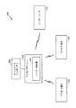
図3は、例示的な通信システム300(たとえば、通信ネットワークの一部)のいくつかのノードを示す。例示のために、互いに通信する、1つまたは複数のアクセス端末、アクセスポイント、およびネットワークエンティティのコンテキストにおいて、本開示の様々な態様を説明する。しかしながら、本明細書の教示は、他の専門用語を使用して参照される、他のタイプの装置または他の同様の装置に適用可能であり得ることを諒解されよう。たとえば、様々な実装形態では、アクセスポイントは、基地局、ノードB、eノードB、ホームノードB、ホームeノードB、スモールセル、マクロセル、フェムトセルなどと呼ばれるか、またはそれらとして実装される可能性があるが、アクセス端末は、ユーザ機器(UE)、移動局などと呼ばれるか、またはそれらとして実装される可能性がある。 FIG. 3 shows several nodes of an exemplary communication system 300 (eg, part of a communication network). For purposes of illustration, various aspects of the present disclosure are described in the context of one or more access terminals, access points, and network entities that communicate with one another. However, it will be appreciated that the teachings herein may be applicable to other types of devices or other similar devices, which are referred to using other terminology. For example, in various implementations, the access point may be referred to or implemented as a base station, Node B, eNodeB, home NodeB, home eNodeB, small cell, macro cell, femto cell, etc. Although the access terminal may be referred to or implemented as a user equipment (UE), a mobile station, etc.
システム300内のアクセスポイントは、システム300のカバレッジエリア内に設置され得るか、あるいはそのカバレッジエリア全体を移動し得る、1つもしくは複数のワイヤレス端末(たとえば、アクセス端末302またはアクセス端末304)のために、1つもしくは複数のサービス(たとえば、ネットワーク接続)に対するアクセスを提供する。たとえば、様々な時点において、アクセス端末302は、アクセスポイント306、またはシステム300内の何らかの他のアクセスポイント(図示せず)に接続し得る。同様に、アクセス端末304は、アクセスポイント306または何らかの他のアクセスポイントに接続し得る。
An access point within
アクセスポイントの各々は、広いエリアのネットワーク接続を容易にするために、互いに通信することを含めて、(便宜的にネットワークエンティティ308により代表される)1つまたは複数のネットワークエンティティと通信することができる。そのようなネットワークエンティティのうちの2つ以上は、コロケートされている可能性があり、かつ/または、そのようなネットワークエンティティのうちの2つ以上は、ネットワーク全体に分布している可能性がある。 Each of the access points may communicate with one or more network entities (for convenience represented by network entity 308), including communicating with each other to facilitate wide area network connectivity. it can. Two or more of such network entities may be co-located and / or two or more of such network entities may be distributed throughout the network .
ネットワークエンティティは、たとえば、1つもしくは複数の無線ネットワークエンティティおよび/またはコアネットワークエンティティなどの様々な形態をとり得る。したがって、様々な実装形態では、ネットワークエンティティ308は、ネットワーク管理(たとえば、運用、アドミニストレーション、管理、およびプロビジョニングのエンティティを介した)、呼制御、セッション管理、モビリティ管理、ゲートウェイ機能、インターワーキング機能、またはいくつかの他の適切なネットワーク機能のうちの少なくとも1つなどの機能を表すことができる。いくつかの態様では、モビリティ管理は、追跡エリア、位置エリア、ルーティングエリア、またはいくつかの他の適切な技法の使用を通してアクセス端末の現在位置を追跡するステップと、アクセス端末のページングを制御するステップと、アクセス端末にアクセス制御を提供するステップとに関する。
The network entities may take various forms, such as, for example, one or more wireless network entities and / or core network entities. Thus, in various implementations, the
図3を参照して上で示したように、アクセスポイント306(または、システム300内の任意の他のデバイス)におけるワイヤレス信号の受信は、レーダーソース310からの干渉を受ける場合がある。本明細書の教示によれば、アクセスポイント306は、レーダー検出を実現するレーダー検出器312を含む。
As indicated above with reference to FIG. 3, reception of wireless signals at access point 306 (or any other device in system 300) may be subject to interference from
いくつかの実装形態では、レーダー検出器312は、電磁放射を受信して、その電磁放射がレーダーソース310からの送信であるかどうかを判定するように構成され得る。レーダー送信は、たとえば、そのパルス幅、パルス反復間隔、およびある時間期間内に送信されたパルスの数によって特徴付けられる種々のタイプに分類され得る。当業者は、レーダー送信が分類され得る他の特徴を理解されよう。レーダー検出器312は、たとえば、電磁放射の特性と様々なレーダータイプの特性との間に整合が存在するかどうかを判定するように構成され得る。整合が存在する場合、レーダー検出器312は、たとえば、電磁放射の電力レベルがしきい値を超えるかどうかを判定することができる。電磁放射の電力レベルがしきい値を超える場合、レーダー検出器312は、たとえば、装置306に、ダウンリンク通信を動的周波数選択(DFS:Dynamic Frequency Selection)によって必要とされる異なるチャネルに変更させることが可能である。
In some implementations,
図3の例では、アクセスポイント306は、レーダー検出器312を含むとして示されている。異なる実装形態では、レーダー検出器312の機能のうちのいくつかまたはすべては異なるエンティティ内に具現化され得る。たとえば、いくつかの実装形態では、アクセス端末はレーダー検出を採用することができる。
In the example of FIG. 3,
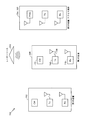
図4は、従来の時分割複信構成400の図である。構成400は、第1の装置402と第2の装置452とを含む。第1の装置402は、送信機404と、受信機406と、アンテナ408と、スイッチ410とを含む。第2の装置452は、送信機454と、受信機456と、アンテナ458と、スイッチ460とを含む。時分割複信を用いて、第1の装置402から第2の装置452への通信および第2の装置452から第1の装置402への通信が同じキャリア周波数において実行される。通信は、時間間隔ごとにデータ量単位にパースされる。そのような単位はフレームとして知られている。フレーム自体がいくつかのサブフレームにパースされる。時分割複信を用いて、通信は、第1のサブフレームの間、第1の方向に(たとえば、第1の装置402から第2の装置452に)生じ、第2のサブフレームの間、第2の方向に(たとえば、第2の装置425から第1の装置402に)生じる。
FIG. 4 is a diagram of a conventional time
たとえば、第1のサブフレームの間、スイッチ410は送信機404をアンテナ408に結合し、スイッチ460は受信機456をアンテナ458に結合し、その結果、第1の装置402から第2の装置452への第1の方向に通信が生じる。第1の装置402が、アクセスポイント、ノードB、発展型ノードB、無線ネットワークコントローラ、基地局、無線基地局、基地局コントローラ、送受信機基地局、送受信機機能、無線送受信機、無線ルータ、基本サービスセット、拡張サービスセット、マクロセル、マクロノード、ホームeNB、フェムトセル、フェムトノード、ピコノード、リレーノードなどのうちの少なくとも1つの機能を実行するように構成され、第2の装置452がアクセス端末などである場合、第1の方向の通信はダウンリンクとして知られる。
For example, during the first subframe, switch 410
たとえば、第2のサブフレームの間、スイッチ410は受信機406をアンテナ408に結合し、スイッチ460は送信機454をアンテナ458に結合し、その結果、第2の装置452から第1の装置402への第2の方向に通信が生じる。第1の装置402が、アクセスポイント、ノードB、発展型ノードB、無線ネットワークコントローラ、基地局、無線基地局、基地局コントローラ、送受信機基地局、送受信機機能、無線送受信機、無線ルータ、基本サービスセット、拡張サービスセット、マクロセル、マクロノード、ホームeNB、フェムトセル、フェムトノード、ピコノード、リレーノードなどのうちの少なくとも1つの機能を実行するように構成される場合、第2の方向の通信はアップリンクとして知られる。
For example, during the second subframe, switch 410
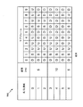
図5は、ロングタームエボリューション(LTE)時分割複信(TDD)規格によるフレームの所定の構成の図500である。LTE TDD規格の各フレームは、10個のサブフレーム(すなわち、サブフレーム0から9)を含む。LTE TDD規格は、サブフレームの間に通信の指定された方向に基づいて、フレームの7つの構成(すなわち、構成0から6)を提供する。たとえば、LTE TDD規格の構成0では、サブフレーム0および5はダウリンク(D)方向の通信用に指定され、サブフレーム2、3、4、7、8、および9はアップリンク(U)方向の通信用に指定され、サブフレーム1および6は特別サブフレームとして指定される。同様に、たとえば、LTE TDD規格の構成1では、サブフレーム0、4、5、および9はダウリンク(D)方向の通信用に指定され、サブフレーム2、3、7、および8はアップリンク(U)方向の通信用に指定され、サブフレーム1および6は特別サブフレームとして指定される。
FIG. 5 is a diagram 500 of predetermined configurations of frames in accordance with the Long Term Evolution (LTE) Time Division Duplex (TDD) standard. Each frame of the LTE TDD standard includes 10 subframes (ie,
図4に示した従来の時分割複信構成400および図5に示した図500のLTE TDD規格の構成0を参照すると、たとえば、サブフレーム4(U)の間、スイッチ410は受信機406をアンテナ408に結合し、スイッチ460は送信機454をアンテナ458に結合し、その結果、第2の装置452から第1の装置402へのアップリンク方向に通信が生じる。たとえば、サブフレーム5(D)の間、スイッチ410は送信機404をアンテナ408に結合し、スイッチ460は受信機456をアンテナ458に結合し、その結果、第1の装置402から第2の装置452へのダウンリンク方向に通信が生じる。
Referring to the conventional time
図6は、従来の周波数分割複信構成600の図である。構成600は、第1の装置602と第2の装置652とを含む。第1の装置602は、送信機604と、受信機606と、第1のアンテナ608と、第2のアンテナ610とを含む。第2の装置652は、送信機654と、受信機656と、第1のアンテナ658と、第2のアンテナ660とを含む。周波数分割複信を用いて、第1の装置602から第2の装置652への通信が第1のキャリア周波数において実行され、第2の装置652から第1の装置602への通信が第2のキャリア周波数において実行される。周波数分割複信を用いて、通信は、第1の方向に(たとえば、第1のワイヤレス装置602から第2のワイヤレス装置652に)、かつ第2の方向に(たとえば、第2のワイヤレス装置652から第1のワイヤレス装置602に)同時に生じる。それでもなお、通信は依然としてフレームにパースされ、フレーム自体がサブフレームにパースされる。
FIG. 6 is a diagram of a conventional frequency
たとえば、第1の方向の通信は第1のアンテナ608を介して送信機604から第2のアンテナ660を介して受信機656に対して第1のキャリア周波数において生じ、同時に、第2の方向の通信が第1のアンテナ658を介して送信機654から第2のアンテナ610を介して受信機606に対して第2のキャリア周波数において生じる。第1の装置602が、アクセスポイント、ノードB、発展型ノードB、無線ネットワークコントローラ、基地局、無線基地局、基地局コントローラ、送受信機基地局、送受信機機能、無線送受信機、無線ルータ、基本サービスセット、拡張サービスセット、マクロセル、マクロノード、ホームeNB、フェムトセル、フェムトノード、ピコノード、リレーノードなどのうちの少なくとも1つの機能を実行するように構成され、第2の装置652がアクセス端末などである場合、第1の方向の通信はダウンリンクとして知られ、第1のキャリア周波数はダウンリンク周波数帯域を定義する。第1の装置602が、アクセスポイント、ノードB、発展型ノードB、無線ネットワークコントローラ、基地局、無線基地局、基地局コントローラ、送受信機基地局、送受信機機能、無線送受信機、無線ルータ、基本サービスセット、拡張サービスセット、マクロセル、マクロノード、ホームeNB、フェムトセル、フェムトノード、ピコノード、リレーノードなどのうちの少なくとも1つの機能を実行するように構成され、第2の装置652がアクセス端末などである場合、第2の方向の通信はアップリンクとして知られ、第2のキャリア周波数はアップリンク周波数帯域を定義する。
For example, communication in the first direction may occur from the
実際には、ワイヤレスネットワークは、典型的には、アップリンク方向よりもダウンリンク方向でかなりより多くの量のデータフローを経験することを当業者は理解されよう。これは、周波数分割複信モードで動作するワイヤレス通信システムが、動的周波数選択(DFS)を実装して、ダウンリンク周波数帯域内でレーダー送信の存在を検出する能力を複雑にする。 It will be appreciated by those skilled in the art that, in practice, wireless networks typically experience much greater amounts of data flow in the downlink direction than in the uplink direction. This complicates the ability of a wireless communication system operating in frequency division duplex mode to implement dynamic frequency selection (DFS) to detect the presence of radar transmission in the downlink frequency band.
図7は、本開示による、ワイヤレスネットワーク700においてレーダー検出を管理するための第1の装置306の一例の図である。ワイヤレスネットワーク700はまた、第2の装置702と第3の装置704とを含み得る。たとえば、第1の装置306は、アクセスポイント、ノードB、発展型ノードB、無線ネットワークコントローラ、基地局、無線基地局、基地局コントローラ、送受信機基地局、送受信機機能、無線送受信機、無線ルータ、基本サービスセット、拡張サービスセット、マクロセル、マクロノード、ホームeNB、フェムトセル、フェムトノード、ピコノード、リレーノードなどのうちの少なくとも1つの機能を実行するように構成され得る。たとえば、第2の装置702は、アクセスポイント、ノードB、発展型ノードB、無線ネットワークコントローラ、基地局、無線基地局、基地局コントローラ、送受信機基地局、送受信機機能、無線送受信機、無線ルータ、基本サービスセット、拡張サービスセット、マクロセル、マクロノード、ホームeNB、フェムトセル、フェムトノード、ピコノード、リレーノードなどのうちの少なくとも1つの機能を実行するように構成され得る。たとえば、第3の装置704はアクセス端末302であり得る。
FIG. 7 is a diagram of an example of a
第1の装置306は、送信機706と、スイッチ708と、回路710とを含み得る。第1の装置306は、ワイヤレスネットワーク700において他の装置(たとえば、第2の装置702、第3の装置704など)と通信するように構成され得る。送信機706は、周波数分割複信モードで動作し、第1の信号を第2の装置702、第3の装置704、または両方に送るように構成され得る。第1の信号はレーダーソース310からの送信を監視することに関し得る。スイッチ708は、送信機706に、レーダーソース310からの送信の検出に先立って、ダウンリンク周波数帯域のフレームのいくつかのサブフレームの間に送信するのを控えさせるように構成され得る。たとえば、スイッチ708は、レーダーソース310からの送信の検出に先立って、ダウンリンク周波数帯域のフレームのその数のサブフレームの間に開位置に配置され得る。レーダーソース310からの送信の監視は、送信するのを控えるサブフレームの間に生じ得る。回路710は、事象に応じて、ダウンリンク周波数帯域のフレームのサブフレームの数を変更するように構成され得る。
The
スイッチ708は、たとえば、リレー、半導体デバイス、微小電気機械スイッチ、またはそれらデバイスの組合せを含み得る。装置306の実装形態がスイッチ708なしで達成され得るように、送信機706にダウンリンク周波数帯域のフレームのその数のサブフレームの間に送信するのを控えさせることができる他の様式を当業者は理解されよう。たとえば、送信機706は、送信に先立って入力信号(図示せず)を変調すること、および、この期間の間に入力信号が送信機706に入力されるのを防ぐことによって、またはこの期間の間に入力信号が送信機706によって変調されるのを防ぐことによって、送信機706にダウンリンク周波数帯域のフレームのその数のサブフレームの間に送信するのを控えさせることが可能であることを当業者は理解されよう。
本開示の実装形態はダウンリンク周波数帯域のフレーム内のサブフレームの特定の配置に依存しないが、そうすることからある利点が実現され得る。 Although implementations of the present disclosure do not depend on the particular arrangement of subframes in the downlink frequency band frame, certain advantages may be realized from doing so.
たとえば、ダウンリンク周波数帯域のフレーム内のサブフレームの配置は、ロングタームエボリューション(LTE)時分割複信(TDD)規格に従って構成されたフレーム内のアップリンク通信用に指定されたサブフレームの配置に対応し得る。時分割複信および周波数分割複信の各々の利点ならびに欠点を当業者は認識されよう。さらに、これらのモードの各々は特定の利点を有するため、LTE規格は両方のモードで動作し得るワイヤレスシステム用のプロセスを組み込む。有利には、ダウンリンク周波数帯域のフレーム内のサブフレームの配置をLTE TDD規格によるアップリンク通信用に指定されたサブフレームの配置に対応させることは、時分割複信モードと周波数分割複信モードの両方での動作を促す。 For example, the arrangement of subframes in a frame of the downlink frequency band is the arrangement of subframes designated for uplink communication in a frame configured according to the Long Term Evolution (LTE) Time Division Duplex (TDD) standard It can correspond. Those skilled in the art will appreciate the advantages and disadvantages of time division duplexing and frequency division duplexing, respectively. Furthermore, because each of these modes has particular advantages, the LTE standard incorporates a process for wireless systems that can operate in both modes. Advantageously, the arrangement of subframes in the frame of the downlink frequency band corresponds to the arrangement of subframes designated for uplink communication according to the LTE TDD standard: time division duplex mode and frequency division duplex mode Encourages action on both.
たとえば、ダウンリンク周波数帯域のフレーム内のサブフレームの配置は、LTE TDD規格の第1の構成に従って構成されたフレーム内のアップリンク通信用に指定されたサブフレームの配置に対応し得る。たとえば、図5に示した図500のLTE TDD規格を参照すると、ダウンリンク周波数帯域のフレーム内のサブフレームの配置は、サブフレーム2、3、7、および8、計4個のサブフレームである、LTE TDD規格の構成1に従って構成されたフレーム内のアップリンク通信用に指定されたサブフレームの配置に対応し得る。図7に戻ると、本態様によれば、回路710は、サブフレームの数を変更するために、LTE TDD規格の第2の構成に従って構成されたフレーム内のアップリンク通信用に指定されたサブフレームの配置に対応するように、ダウンリンク周波数帯域のフレーム内のサブフレームの配置を変更するように構成され得る。たとえば、図5に示した図500のLTE TDD規格を参照すると、ダウンリンク周波数帯域のフレーム内のサブフレームの配置は、サブフレーム2、計1個のサブフレームである、LTE TDD規格の構成5に従って構成されたフレーム内のアップリンク通信用に指定されたサブフレームの配置に対応するように変更され得る。
For example, the arrangement of subframes in a frame of the downlink frequency band may correspond to the arrangement of subframes designated for uplink communication in a frame configured according to the first configuration of the LTE TDD standard. For example, referring to the LTE TDD standard of the diagram 500 shown in FIG. 5, the arrangement of subframes in a frame of the downlink frequency band is subframes 2, 3, 7, and 8, for a total of four subframes , May correspond to an arrangement of subframes designated for uplink communication in a frame configured according to
図7に戻ると、回路710は、第1の装置306の負荷の増大を判定するようにさらに構成され得る。本態様によれば、回路710は、サブフレームの数を変更するために、第1の装置306の負荷の増大に応じて、サブフレームの数を低減させるように構成され得る。たとえば、図5に示した図500のLTE TDD規格を参照すると、ダウンリンク周波数帯域のフレーム内のサブフレームの配置が、サブフレーム2、3、7、および8、計4個のサブフレームである、LTE TDD規格の構成1に従って構成されたフレーム内のアップリンク通信用に指定されたサブフレームの配置に対応する場合、回路710は、第1の装置306の負荷の増大に応じて、サブフレームの数を低減させるために、サブフレーム2および7、計2個のサブフレームである、LTE TDD規格の構成2に従って構成されるように、フレーム内のアップリンク通信用に指定されたサブフレームの配置を変更するように構成され得る。送信するのを控えるサブフレームの数を4(たとえば、LTE TDD規格の構成1)から2(たとえば、LTE TDD規格の構成2)に低減させることは、第1の装置306の負荷の増大を満たすために、送信のためにより多くのサブフレームが使用されることを可能にする。この説明した例では、LTE TDD規格の構成1からLTE TDD規格の構成2への変更は、結果として、ダウンリンク通信用に指定されたサブフレームの数を4(たとえば、サブフレーム0、4、5、および9)から6(たとえば、サブフレーム0、3、4、5、8、および9)に増大させ、その結果、第1の装置306の負荷の増大を満たす目的で送信するためにより多くのサブフレームが利用可能になる。
Returning to FIG. 7, the
図7に戻ると、回路710は、第1の装置306の負荷の低減を判定するようにさらに構成され得る。本態様によれば、回路710は、サブフレームの数を変更するために、第1の装置306の負荷の低減に応じて、サブフレームの数を増大させるように構成され得る。たとえば、図5に示した図500のLTE TDD規格を参照すると、ダウンリンク周波数帯域のフレーム内のサブフレームの配置が、サブフレーム2、3、7、および8、計4個のサブフレームである、LTE TDD規格の構成1に従って構成されたフレーム内のアップリンク通信用に指定されたサブフレームの配置に対応する場合、回路710は、第1の装置306の負荷の低減に応じて、サブフレームの数を増大させるために、サブフレーム2、3、4、7、8、および9、計6個のサブフレームである、LTE TDD規格の構成0に従って構成されるように、フレーム内のアップリンク通信用に指定されたサブフレームの配置を変更するように構成され得る。送信するのを控えるサブフレームの数を4(たとえば、LTE TDD規格の構成1)から6(たとえば、LTE TDD規格の構成0)に増大させることは、レーダーソース310からの送信を監視するためにより多くのサブフレームが使用されることを可能にする。この説明した例では、LTE TDD規格の構成1からLTE TDD規格の構成0への変更は、結果として、アップリンク通信用に指定されたサブフレームの数を4(たとえば、サブフレーム2、3、7、および8)から6(たとえば、サブフレーム2、3、4、7、8、および9)に増大させ、その結果、レーダーソース310からの送信を監視するためにより多くのサブフレームが利用可能になる。
Returning to FIG. 7, the
図7に戻ると、場合によっては、第1の装置306は受信機712をさらに含み得る。受信機712は、第2の装置702、第3の装置704、または両方から第2の信号を受信するように構成され得る。第2の信号は、レーダーソース310からの送信を検出することに関し得る。本態様によれば、回路710は、第2の信号の受信に応じて、サブフレームの数を変更するように構成され得る。
Returning to FIG. 7, in some cases, the
場合によっては、回路710は、サブフレームの数を変更するために、第2の信号の受信に応じて、サブフレームの数を増大させるように構成され得る。たとえば、図5に示した図500のLTE TDD規格を参照すると、ダウンリンク周波数帯域のフレーム内のサブフレームの配置が、サブフレーム2、3、7、および8、計4個のサブフレームである、LTE TDD規格の構成1に従って構成されたフレーム内のアップリンク通信用に指定されたサブフレームの配置に対応する場合、回路710は、第2の信号の受信に応じて、サブフレームの数を増大させるために、サブフレーム2、3、4、7、8、および9、計6個のサブフレームである、LTE TDD規格の構成0に従って構成されるように、フレーム内のアップリンク通信用に指定されたサブフレームの配置を変更するように構成され得る。送信するのを控えるサブフレームの数を4(たとえば、LTE TDD規格の構成1)から6(たとえば、LTE TDD規格の構成0)に増大させることは、第2の信号の受信の観点から、送信のためにより少ないサブフレームが使用され、レーダーソース310からの送信を監視するためにより多くのサブフレームが使用されることを可能にする。この説明した例では、LTE TDD規格の構成1からLTE TDD規格の構成0への変更は、結果として、アップリンク通信用に指定されたサブフレームの数を4(たとえば、サブフレーム2、3、7、および8)から6(たとえば、サブフレーム2、3、4、7、8、および9)に増大させ、その結果、レーダーソース310からの送信を監視するためにより多くのサブフレームが利用可能になり、結果として、ダウンリンク通信用に指定されたサブフレームの数を4(たとえば、サブフレーム0、4、5、および9)から2(たとえば、サブフレーム0および5)に低減させ、その結果、送信するためにより少ないサブフレームが利用可能になり、レーダーソース310からの送信との干渉の可能性を低下させる。
In some cases,
代替的に、第2の信号は、第1の装置306にダウンリンク通信を動的周波数選択(DFS)によって要求される異なるチャネルに変更させることが可能である。
Alternatively, the second signal may cause the
図7に戻ると、場合によっては、回路710は、サブフレームの数がしきい値未満であることに応じて、送信機706に、第1の信号を第2の装置702、第3の装置704、または両方に送らせるようにさらに構成され得る。たとえば、図5に示した図500のLTE TDD規格を参照すると、送信するのを控えるダウンリンク周波数帯域のフレーム内のサブフレームの数に関するしきい値が2であり、ダウンリンク周波数帯域のフレーム内のサブフレームの配置が、サブフレーム2、すなわち、合計が、しきい値未満である1個のサブフレームである、LTE TDD規格の構成5に従って構成されたフレーム内のアップリンク通信用に指定されたサブフレームの配置に対応するように変更する場合、回路710は、送信機706に第1の信号を第2の装置702、第3の装置704、または両方に送らせるようにさらに構成され得る。上で説明したように、そのような状況は、回路710が、サブフレームの数を変更するために、サブフレームの数を低減させるように構成され得る、第1の装置306の負荷の増大に応じて生じ得る。
Returning to FIG. 7, in some cases,
場合によっては、第3の装置704がアクセス端末302である場合、第1の信号はレーダーソース310からの送信を監視するためにアクセス端末302を指定させるように構成され得る。この状況では、レーダーソース310からの送信を監視することは、第1の装置306とアクセス端末302の両方によって実行され得るか、またはアクセス端末302だけによって実行され得る。ワイヤレスネットワーク700が2つ以上のアクセス端末(たとえば、アクセス端末302、アクセス端末304など)を含む場合、レーダーソース310からの送信を監視することは、ワイヤレスネットワーク700におけるアクセス端末のうちの1つ、いくつか、またはすべてを含めて、アクセス端末のうちの1つもしくは複数によって実行され得る。
In some cases, if the third device 704 is the
場合によっては、第2の装置702が、アクセスポイント、ノードB、発展型ノードB、無線ネットワークコントローラ、基地局、無線基地局、基地局コントローラ、送受信機基地局、送受信機機能、無線送受信機、無線ルータ、基本サービスセット、拡張サービスセット、マクロセル、マクロノード、ホームeNB、フェムトセル、フェムトノード、ピコノード、リレーノードなどのうちの少なくとも1つの機能を実行するように構成される場合、第1の信号は、第2の装置702がレーダーソース310からの送信を検出することに応じて、第2の信号を第1の装置306に送ることを第2の装置702に要求するように構成され得る。回路710は、サブフレームの数を変更するために、第2の信号の受信に応じて、サブフレームの数を増大させるように構成され得る。代替的に、第2の信号は、第1の装置306にダウンリンク通信を動的周波数選択(DFS)によって要求される異なるチャネルに変更させることが可能である。
In some cases, the
本開示の様々な態様を組み合わせることが可能である。たとえば、回路710は、第1の装置306の負荷の増大に応じて、LTE TDD規格に従って構成されたフレーム内のアップリンク通信用に指定されたサブフレームの配置を変更することによって、送信するのを控えるダウンリンク周波数帯域のフレーム内のサブフレームの数を低減させるように構成され得る。サブフレームの数の低減の結果が、送信するのを控えるダウンリンク周波数帯域のフレーム内のサブフレームの数がしきい値未満であることである場合、回路710は、第1の信号を第2の装置702、第3の装置704、または両方に送るように構成され得る。第3の装置704がアクセス端末302である場合、第1の信号は、レーダーソース310からの送信を監視するためにアクセス端末302を指定させるように構成され得る。第2の装置702が、アクセスポイント、ノードB、発展型ノードB、無線ネットワークコントローラ、基地局、無線基地局、基地局コントローラ、送受信機基地局、送受信機機能、無線送受信機、無線ルータ、基本サービスセット、拡張サービスセット、マクロセル、マクロノード、ホームeNB、フェムトセル、フェムトノード、ピコノード、リレーノードなどのうちの少なくとも1つの機能を実行するように構成される場合、第1の信号は、第2の装置702がレーダーソース310からの送信を検出することに応じて、第2の信号を第1の装置306に送ることを第2の装置702に要求するように構成され得る。
It is possible to combine the various aspects of the present disclosure. For example, the
この説明した例に加えて、本開示の様々な態様を組み合わせることが可能である他の方法を当業者は理解されよう。したがって、態様の組合せはこの説明した例に限定されない。 Those skilled in the art will appreciate other ways in which various aspects of the present disclosure can be combined in addition to the described examples. Thus, the combination of aspects is not limited to the described example.
図8は、本開示による、ワイヤレスネットワークにおいてレーダー検出を管理するための方法800の一例のフローチャートである。図8では、方法800の随意の動作が破線ブロックで示されている。方法800では、動作802で、ワイヤレスネットワークにおいて他の装置と通信するように構成され、周波数分割複信モードで動作する第1の装置に、レーダー送信の検出に先立って、ダウンリンク周波数帯域のフレームのいくつかのサブフレームの間に送信するのを控えさせることが可能である。たとえば、図7を参照すると、ワイヤレスネットワーク700において他の装置(たとえば、第2の装置702、第3の装置704など)と通信するように構成され、周波数分割複信モードで動作する第1の装置306は、スイッチ708を含み得る。たとえば、スイッチ708をダウンリンク周波数帯域のフレームのいくつかのサブフレームの間に開位置に配置することによって、第1の装置306に、レーダーソース310からの送信の検出に先立って、ダウンリンク周波数帯域のフレームのその数のサブフレームの間に送信するのを控えさせることが可能である。
FIG. 8 is a flowchart of an example of a
限定ではなく、例として、非一時的コンピュータ可読記録媒体は電子プロセッサに動作802を実行させるための少なくとも1つの命令を含み得ることを当業者は理解されよう。
Those skilled in the art will appreciate that, by way of example and not limitation, non-transitory computer readable storage medium may include at least one instruction for causing an electronic processor to perform
図8に戻ると、動作804で、第1の装置に第1の信号を別の装置に送らせることが可能である。第1の信号はレーダー送信を監視することに関し得る。場合によっては、第1の信号は、無線リソース制御プロトコルに従って構成され得る。たとえば、図7を参照すると、第1の装置306は送信機706を含むことが可能であり、送信機706は、第1の信号を第2の装置702、第3の装置704、または両方に送るように構成され得る。
Returning to FIG. 8, at
限定ではなく、例として、非一時的コンピュータ可読記録媒体は電子プロセッサに動作804を実行させるための少なくとも1つの命令を含み得ることを当業者は理解されよう。
Those skilled in the art will appreciate that, by way of example and not limitation, non-transitory computer readable storage medium may include at least one instruction for causing an electronic processor to perform
図8に戻ると、動作806で、第1の装置に、事象に応じて、ダウンリンク周波数帯域のフレームのサブフレームの数を変更させることが可能である。たとえば、図7を参照すると、第1の装置306は回路710を含むことが可能であり、回路710は、事象に応じて、ダウンリンク周波数帯域のフレームのサブフレームの数を変更するように構成され得る。
Returning to FIG. 8, at
限定ではなく、例として、非一時的コンピュータ可読記録媒体は電子プロセッサに動作806を実行させるための少なくとも1つの命令を含み得ることを当業者は理解されよう。
Those skilled in the art will appreciate that, by way of example and not limitation, non-transitory computer readable storage medium may include at least one instruction for causing an electronic processor to perform
本開示の実装形態はダウンリンク周波数帯域のフレーム内のサブフレームの特定の配置に依存しないが、そうすることからある利点が実現され得る。 Although implementations of the present disclosure do not depend on the particular arrangement of subframes in the downlink frequency band frame, certain advantages may be realized from doing so.
たとえば、ダウンリンク周波数帯域のフレーム内のサブフレームの配置は、ロングタームエボリューション(LTE)時分割複信(TDD)規格に従って構成されたフレーム内のアップリンク通信用に指定されたサブフレームの配置に対応し得る。時分割複信および周波数分割複信の各々の利点ならびに欠点を当業者は認識されよう。さらに、これらのモードの各々は特定の利点を有するため、LTE規格は両方のモードで動作し得るワイヤレスシステム用のプロセスを組み込む。有利には、ダウンリンク周波数帯域のフレーム内のサブフレームの配置をLTE TDD規格によるアップリンク通信用に指定されたサブフレームの配置に対応させることは、時分割複信モードと周波数分割複信モードの両方での動作を促す。 For example, the arrangement of subframes in a frame of the downlink frequency band is the arrangement of subframes designated for uplink communication in a frame configured according to the Long Term Evolution (LTE) Time Division Duplex (TDD) standard It can correspond. Those skilled in the art will appreciate the advantages and disadvantages of time division duplexing and frequency division duplexing, respectively. Furthermore, because each of these modes has particular advantages, the LTE standard incorporates a process for wireless systems that can operate in both modes. Advantageously, the arrangement of subframes in the frame of the downlink frequency band corresponds to the arrangement of subframes designated for uplink communication according to the LTE TDD standard: time division duplex mode and frequency division duplex mode Encourages action on both.
たとえば、ダウンリンク周波数帯域のフレーム内のサブフレームの配置は、LTE TDD規格の第1の構成に従って構成されたフレーム内のアップリンク通信用に指定されたサブフレームの配置に対応し得る。たとえば、図5に示した図500のLTE TDD規格を参照すると、ダウンリンク周波数帯域のフレーム内のサブフレームの配置は、サブフレーム2、3、7、および8、計4個のサブフレームである、LTE TDD規格の構成1に従って構成されたフレーム内のアップリンク通信用に指定されたサブフレームの配置に対応し得る。図8に戻ると、本態様によれば、LTE TDD規格の第2の構成に従って構成されたフレーム内のアップリンク通信用に指定されたサブフレームの配置に対応するように、ダウンリンク周波数帯域のフレーム内のサブフレームの配置を変更することによって、第1の装置にダウンリンク周波数帯域のフレームのサブフレームの数を変更させることが可能である。たとえば、図5に示した図500のLTE TDD規格を参照すると、ダウンリンク周波数帯域のフレーム内のサブフレームの配置は、サブフレーム2、計1個のサブフレームである、LTE TDD規格の構成5に従って構成されたフレーム内のアップリンク通信用に指定されたサブフレームの配置に対応するように変更され得る。
For example, the arrangement of subframes in a frame of the downlink frequency band may correspond to the arrangement of subframes designated for uplink communication in a frame configured according to the first configuration of the LTE TDD standard. For example, referring to the LTE TDD standard of the diagram 500 shown in FIG. 5, the arrangement of subframes in a frame of the downlink frequency band is subframes 2, 3, 7, and 8, for a total of four subframes , May correspond to an arrangement of subframes designated for uplink communication in a frame configured according to
場合によっては、第1の装置は、アクセスポイント、ノードB、発展型ノードB、無線ネットワークコントローラ、基地局、無線基地局、基地局コントローラ、送受信機基地局、送受信機機能、無線送受信機、無線ルータ、基本サービスセット、拡張サービスセット、マクロセル、マクロノード、ホームeNB、フェムトセル、フェムトノード、ピコノード、リレーノードなどのうちの少なくとも1つの機能を実行するように構成され得る。 In some cases, the first device may be an access point, Node B, evolved Node B, radio network controller, base station, radio base station, base station controller, transceiver base station, transceiver function, radio transceiver, radio It may be configured to perform at least one function of a router, a basic service set, an enhanced service set, a macro cell, a macro node, a home eNB, a femto cell, a femto node, a pico node, a relay node, and so on.
図8に戻ると、場合によっては、動作808で、第1の装置に第1の装置の負荷の増大を判定させることが可能である。本態様によれば、第1の装置の負荷の増大に応じて、ダウンリンク周波数帯域のフレームのサブフレームの数を低減させることによって、第1の装置にダウンリンク周波数帯域のフレームのサブフレームの数を変更させること(動作806)が可能である。
Returning to FIG. 8, in some cases, at
たとえば、図5に示した図500のLTE TDD規格を参照すると、ダウンリンク周波数帯域のフレーム内のサブフレームの配置が、サブフレーム2、3、7、および8、計4個のサブフレームである、LTE TDD規格の構成1に従って構成されたフレーム内のアップリンク通信用に指定されたサブフレームの配置に対応する場合、サブフレーム2および7、計2個のサブフレームである、LTE TDD規格の構成2に従って構成されるように、フレーム内のアップリンク通信用に指定されたサブフレームの配置を変更することによって、第1の装置にダウンリンク周波数帯域のフレームのサブフレームの数を低減させることが可能である。送信するのを控えるサブフレームの数を4(たとえば、LTE TDD規格の構成1)から2(たとえば、LTE TDD規格の構成2)に低減することは、第1の装置の負荷の増大を満たす目的で送信するためにより多くのサブフレームが使用されることを可能にする。この説明した例では、LTE TDD規格の構成1からLTE TDD規格の構成2への変更は、結果として、ダウンリンク通信用に指定されたサブフレームの数を4(たとえば、サブフレーム0、4、5、および9)から6(たとえば、サブフレーム0、3、4、5、8、および9)に増大させ、その結果、第1の装置の負荷の増大を満たす目的で送信するためにより多くのサブフレームが利用可能になる。
For example, referring to the LTE TDD standard of the diagram 500 shown in FIG. 5, the arrangement of subframes in the frame of the downlink frequency band is subframes 2, 3, 7, and 8, for a total of four subframes ,
場合によっては、第1の装置に、ダウンリンク周波数帯域のフレームのサブフレームの数をゼロに低減させること(動作806)が可能であり、その結果、ダウンリンク周波数帯域のフレームのサブフレームのすべてが送信のために使用され得る。この状況で、LTE TDD規格の構成のいずれもアップリンク通信用に指定されたゼロサブフレームを有さないため、ダウンリンク周波数帯域のフレーム内のサブフレームの配置はLTE TDD規格に従って構成されたフレーム内のアップリンク通信用に指定されたサブフレームの配置に対応しないことになる。 In some cases, it is possible for the first device to reduce the number of subframes in the downlink frequency band frame to zero (operation 806), such that all subframes in the downlink frequency band are framed. May be used for transmission. In this situation, none of the LTE TDD standard configurations have zero subframes designated for uplink communication, so the arrangement of subframes in the downlink frequency band frame is a frame configured according to the LTE TDD standard It does not correspond to the arrangement of subframes designated for uplink communication within.
限定ではなく、例として、非一時的コンピュータ可読記録媒体は電子プロセッサに動作808を実行させるための少なくとも1つの命令を含み得ることを当業者は理解されよう。
Those skilled in the art will appreciate that, by way of example and not limitation, non-transitory computer readable storage medium may include at least one instruction for causing an electronic processor to perform
図8に戻ると、場合によっては、動作810で、第1の装置に第1の装置の負荷の低減を判定させることが可能である。本態様によれば、第1の装置の負荷の低減に応じて、ダウンリンク周波数帯域のフレームのサブフレームの数を増大させることによって、第1の装置にダウンリンク周波数帯域のフレームのサブフレームの数を変更させること(動作806)が可能である。
Returning to FIG. 8, in some cases, at
たとえば、図5に示した図500のLTE TDD規格を参照すると、ダウンリンク周波数帯域のフレーム内のサブフレームの配置が、サブフレーム2、3、7、および8、計4個のサブフレームである、LTE TDD規格の構成1に従って構成されたフレーム内のアップリンク通信用に指定されたサブフレームの配置に対応する場合、サブフレーム2、3、4、7、8、および9、計6個のサブフレームである、LTE TDD規格の構成0に従って構成されるように、フレーム内のアップリンク通信用に指定されたサブフレームの配置を変更することによって、第1の装置にダウンリンク周波数帯域のフレームのサブフレームの数を増大させることが可能である。送信するのを控えるサブフレームの数を4(たとえば、LTE TDD規格の構成1)から6(たとえば、LTE TDD規格の構成0)に増大させることは、レーダー送信を監視するためにより多くのサブフレームが使用されることを可能にする。この説明した例では、LTE TDD規格の構成1からLTE TDD規格の構成0への変更は、結果として、アップリンク通信用に指定されたサブフレームの数を4(たとえば、サブフレーム2、3、7、および8)から6(たとえば、サブフレーム2、3、4、7、8、および9)に増大させ、その結果、レーダー送信を監視するためにより多くのサブフレームが利用可能になる。
For example, referring to the LTE TDD standard of the diagram 500 shown in FIG. 5, the arrangement of subframes in the frame of the downlink frequency band is subframes 2, 3, 7, and 8, for a total of four subframes ,
限定ではなく、例として、非一時的コンピュータ可読記録媒体は電子プロセッサに動作810を実行させるための少なくとも1つの命令を含み得ることを当業者は理解されよう。
Those skilled in the art will appreciate that, by way of example and not limitation, non-transitory computer readable storage medium may include at least one instruction for causing an electronic processor to perform
図8に戻ると、場合によっては、動作812で、第1の装置に他の装置から第2の信号を受信させることが可能である。第2の信号はレーダー送信の検出に関し得る。本態様によれば、第1の装置に、第2の信号の受信に応じて、ダウンリンク周波数帯域のフレームのサブフレームの数を変更させること(動作806)が可能である。場合によっては、第2の信号の受信に応じて、ダウンリンク周波数帯域のフレームのサブフレームの数を増大させることによって、第1の装置にダウンリンク周波数帯域のフレームのサブフレームの数を変更させること(動作806)が可能である。
Returning to FIG. 8, in some cases, at
たとえば、図5に示した図500のLTE TDD規格を参照すると、ダウンリンク周波数帯域のフレーム内のサブフレームの配置が、サブフレーム2、3、7、および8、計4個のサブフレームである、LTE TDD規格の構成1に従って構成されたフレーム内のアップリンク通信用に指定されたサブフレームの配置に対応する場合、サブフレーム2、3、4、7、8、および9、計6個のサブフレームである、LTE TDD規格の構成0に従って構成されるように、フレーム内のアップリンク通信用に指定されたサブフレームの配置を変更することによって、第1の装置に、第2の信号の受信に応じて、ダウンリンク周波数帯域のフレームのサブフレームの数を増大させることが可能である。送信するのを控えるサブフレームの数を4(たとえば、LTE TDD規格の構成1)から6(たとえば、LTE TDD規格の構成0)に増大させることは、第2の信号の受信の観点から、送信するために、より少ないサブフレームが使用され、レーダー送信を監視するためにより多くのサブフレームが使用されることを可能にする。この説明した例では、LTE TDD規格の構成1からLTE TDD規格の構成0への変更は、結果として、アップリンク通信用に指定されたサブフレームの数を4(たとえば、サブフレーム2、3、7、および8)から6(たとえば、サブフレーム2、3、4、7、8、および9)に増大させ、その結果、レーダー送信を監視するためにより多くのサブフレームが利用可能になり、結果として、ダウンリンク通信用に指定されたサブフレームの数を4(たとえば、サブフレーム0、4、5、および9)から2(たとえば、サブフレーム0および5)に低減させ、その結果、送信するためにより少ないサブフレームが利用可能になり、レーダー送信との干渉の可能性を低下させる。
For example, referring to the LTE TDD standard of the diagram 500 shown in FIG. 5, the arrangement of subframes in the frame of the downlink frequency band is subframes 2, 3, 7, and 8, for a total of four subframes ,
代替的に、第2の信号は、第1の装置306にダウンリンク通信を動的周波数選択(DFS)によって要求される異なるチャネルに変更させることが可能である。
Alternatively, the second signal may cause the
限定ではなく、例として、非一時的コンピュータ可読記録媒体は電子プロセッサに動作812を実行させるための少なくとも1つの命令を含み得ることを当業者は理解されよう。
Those skilled in the art will appreciate that, by way of example and not limitation, non-transitory computer readable storage medium may include at least one instruction for causing an electronic processor to perform
図8に戻ると、場合によっては、第1の装置に第1の信号を他の装置に送らせること(動作804)は、サブフレームの数がしきい値未満であることに応じ得る。たとえば、図5に示した図500のLTE TDD規格を参照すると、送信するのを控えるダウンリンク周波数帯域のフレーム内のサブフレームの数に関するしきい値が2であり、ダウンリンク周波数帯域のフレーム内のサブフレームの配置が、サブフレーム2、すなわち、合計が、しきい値未満である、1個のサブフレームである、LTE TDD規格の構成5に従って構成されたフレーム内のアップリンク通信用に指定されたサブフレームの配置に対応するように変更する場合、第1の装置に、サブフレームの数がしきい値未満であることに応じて、第1の信号を他の装置に送らせること(動作804)が可能である。上で説明したように、そのような状況は、第1の装置が、サブフレームの数を変更するために、サブフレームの数を低減させるように構成され得る、第1の装置の負荷の増大に応じて生じ得る。
Returning to FIG. 8, in some cases, causing the first device to send the first signal to the other device (act 804) may be responsive to the number of subframes being less than a threshold. For example, referring to the LTE TDD standard of diagram 500 shown in FIG. 5, the threshold for the number of subframes in a frame of the downlink frequency band to refrain from transmitting is 2, and within the frame of the downlink frequency band Designated for uplink communication in a frame configured according to
場合によっては、他の装置が少なくとも1つのアクセス端末である場合、第1の信号は、レーダー送信を監視するために少なくとも1つのアクセス端末を指定させるように構成され得る。この状況では、レーダー送信を監視することは、第1の装置と少なくとも1つのアクセス端末の両方によって実行され得るか、または少なくとも1つのアクセス端末だけによって実行され得る。少なくとも1つのアクセス端末が2つ以上のアクセス端末を含む場合、レーダー送信を監視することは、アクセス端末のうちの1つ、いくつか、またはすべてを含めて、アクセス端末のうちの1つもしくは複数によって実行され得る。 In some cases, where the other device is at least one access terminal, the first signal may be configured to cause the at least one access terminal to be designated to monitor radar transmissions. In this situation, monitoring the radar transmission may be performed by both the first device and the at least one access terminal, or may be performed by only the at least one access terminal. Where at least one access terminal includes more than one access terminal, monitoring the radar transmission may include one or more of the access terminals, including one, some or all of the access terminals. Can be performed by
場合によっては、他の装置が、アクセスポイント、ノードB、発展型ノードB、無線ネットワークコントローラ、基地局、無線基地局、基地局コントローラ、送受信機基地局、送受信機機能、無線送受信機、無線ルータ、基本サービスセット、拡張サービスセット、マクロセル、マクロノード、ホームeNB、フェムトセル、フェムトノード、ピコノード、リレーノードなどのうちの少なくとも1つの機能を実行するように構成される場合、第1の信号は、他の装置がレーダー送信を検出することに応じて、第2の信号を第1の装置に送ることを他の装置に要求するように構成され得る。第1の装置は、サブフレームの数を変更するために、第2の信号の受信に応じて、サブフレームの数を増大させるように構成され得る。代替的に、第2の信号は、第1の装置にダウンリンク通信を動的周波数選択(DFS)によって要求される異なるチャネルに変更させることが可能である。 In some cases, another device may be an access point, Node B, Evolved Node B, radio network controller, base station, radio base station, base station controller, transceiver base station, transceiver function, radio transceiver, radio router The first signal is configured to perform at least one function of: a basic service set, an enhanced service set, a macro cell, a macro node, a home eNB, a femto cell, a femto node, a pico node, a relay node, etc. The other device may be configured to request the other device to send a second signal to the first device in response to detecting the radar transmission. The first apparatus may be configured to increase the number of subframes in response to receiving the second signal to change the number of subframes. Alternatively, the second signal may cause the first device to change downlink communication to a different channel required by dynamic frequency selection (DFS).
図9は、本明細書で教示するレーダー検出動作をサポートするために、装置902、装置904、ならびに装置906(たとえば、それぞれ、アクセス端末、アクセスポイント、およびネットワークエンティティに対応する)に組み込まれ得る(対応するブロックによって表される)いくつかの例示的な構成要素を示す。これらの構成要素は、様々な実装形態で(たとえば、ASIC、SoCなどで)様々なタイプの装置に実装され得ることを諒解されよう。説明する構成要素を通信システム内の他の装置に組み込むこともできる。たとえば、システム内の他の装置は、同様の機能を提供するために説明する構成要素と同様の構成要素を含み得る。また、所与の装置は、説明する構成要素のうちの1つまたは複数を含み得る。たとえば、装置は、装置が複数のキャリア上で動作し、および/または様々な技術を介して通信することを可能にする複数の送受信機構成要素を含み得る。
FIG. 9 may be incorporated into
装置902および装置904は各々、少なくとも1つの指定された無線アクセス技術を介して他のノードと通信するための(それぞれ、通信デバイス908ならびに914(および装置904がリレーである場合は通信デバイス920)によって表される)少なくとも1つのワイヤレス通信デバイスを含む。各通信デバイス908は、信号(たとえば、メッセージ、表示、情報など)を送信し符号化するための(送信機910によって表される)少なくとも1つの送信機と、信号(たとえば、メッセージ、表示、情報、パイロットなど)を受信し復号するための(受信機912によって表される)少なくとも1つの受信機とを含む。同様に、各通信デバイス914は、信号(たとえば、メッセージ、表示、情報、パイロットなど)を送信するための(送信機916によって表される)少なくとも1つの送信機と、信号(たとえば、メッセージ、表示、情報など)を受信するための(受信機918によって表される)少なくとも1つの受信機とを含む。装置904がリレーアクセスポイントである場合、各通信デバイス920は、信号(たとえば、メッセージ、表示、情報、パイロットなど)を送信するための(送信機922によって表される)少なくとも1つの送信機と、信号(たとえば、メッセージ、表示、情報など)を受信するための(受信機924によって表される)少なくとも1つの受信機とを含み得る。
送信機および受信機は、いくつかの実装形態では、(たとえば、単一の通信デバイスの送信機回路および受信機回路として実施される)集積デバイスを含むことができるか、いくつかの実装形態では、独立した送信機デバイスおよび独立した受信機デバイスを含むことができるか、または他の実装形態では、他の方法で実施され得る。いくつかの態様では、装置904のワイヤレス通信デバイス(たとえば、複数のワイヤレス通信デバイスのうちの1つ)は、ネットワークリッスンモジュールを含む。
The transmitter and receiver may include integrated devices (eg, implemented as transmitter circuitry and receiver circuitry of a single communication device) in some implementations, or in some implementations , An independent transmitter device and an independent receiver device may be included, or in other implementations may be implemented in other manners. In some aspects, the wireless communication device (eg, one of the plurality of wireless communication devices) of the
装置906(および、装置904がリレーアクセスポイントでない場合は装置904)は、他のノードと通信するための(通信デバイス926、および場合によっては、920によって表される)少なくとも1つの通信デバイスを含む。たとえば、通信デバイス926は、有線ベースのまたはワイヤレスのバックホールを介して1つもしくは複数のネットワークエンティティと通信するように構成されたネットワークインターフェースを含み得る。いくつかの態様では、通信デバイス926は、有線ベースのまたはワイヤレスの信号通信をサポートするように構成された送受信機として実装され得る。この通信は、たとえば、メッセージ、パラメータ、または他のタイプの情報を送ること、および受信することに関連し得る。したがって、図9の例では、通信デバイス926は、送信機928と受信機930とを含むものとして示されている。同様に、装置904がリレーアクセスポイントでない場合、通信デバイス920は、有線ベースのまたはワイヤレスのバックホールを介して1つもしくは複数のネットワークエンティティと通信するように構成されたネットワークインターフェースを含み得る。通信デバイス926と同様に、通信デバイス920は、送信機922と受信機924とを含むものとして示されている。
Device 906 (and
装置902、904、および906は、本明細書で教示するレーダー検出動作と併せて使用され得る他の構成要素も含む。装置902は、たとえば、本明細書で教示するレーダー検出に関する機能を提供し、他の処理機能を提供するための処理システム932を含む。装置904は、たとえば、本明細書で教示するレーダー検出に関する機能を提供し、他の処理機能を提供するための処理システム934を含む。装置906は、たとえば、本明細書で教示するレーダー検出に関する機能を提供し、他の処理機能を提供するための処理システム936を含む。装置902、904、および906は、それぞれ、情報(たとえば、予約されたリソースを示す情報、しきい値、パラメータなど)を維持するためのメモリデバイス938、940、および942(たとえば、各々がメモリデバイスを含む)を含む。加えて、装置902、904、および906は、それぞれ、ユーザに表示(たとえば、可聴および/または視覚表示)を与えるため、ならびに/または(たとえば、キーパッド、タッチスクリーン、マイクロフォンなどの検知デバイスをユーザが作動させると)ユーザ入力を受信するためのユーザインターフェースデバイス944、946、および948を含む。
便宜上、装置902は、本明細書で説明する様々な例で使用され得る構成要素を含むものとして図9に示す。実際には、示したブロックは、様々な態様において異なる機能を有する可能性がある。たとえば、図8の動作808および/または810をサポートするためのブロック934の機能は、図8の動作812をサポートするためのブロック934の機能とは異なる可能性がある。
For convenience, the
図9の構成要素は、様々な方法で実装され得る。いくつかの実装形態では、図9の構成要素は、たとえば、1つもしくは複数のプロセッサおよび/または(1つもしくは複数のプロセッサを含み得る)1つもしくは複数のASICなど、1つもしくは複数の回路において実装され得る。ここで、各回路は、この機能を提供する回路によって使用される情報または実行可能コードを記憶するための少なくとも1つのメモリ構成要素を使用し、かつ/または組み込み得る。たとえば、ブロック908、932、938、および944によって表される機能のうちのいくつかまたはすべては、装置902のプロセッサならびにメモリ構成要素によって(たとえば、適切なコードの実行によっておよび/またはプロセッサ構成要素の適切な構成によって)実装され得る。同様に、ブロック914、920、934、940、および946によって表される機能のうちのいくつかまたはすべては、装置904のプロセッサならびにメモリ構成要素によって(たとえば、適切なコードの実行によっておよび/またはプロセッサ構成要素の適切な構成によって)実装され得る。また、ブロック926、936、942、および948によって表される機能のうちのいくつかまたはすべては、装置906のプロセッサならびにメモリ構成要素によって(たとえば、適切なコードの実行によっておよび/またはプロセッサ構成要素の適切な構成によって)実装され得る。
The components of FIG. 9 may be implemented in various manners. In some implementations, the components of FIG. 9 may be one or more circuits, such as, for example, one or more processors and / or one or more ASICs (which may include one or more processors). Can be implemented in Here, each circuit may use and / or incorporate at least one memory component for storing information or executable code used by the circuit providing this function. For example, some or all of the functions represented by
上述のように、本明細書で言及されるアクセスポイントのうちのいくつかはスモールセルアクセスポイントを含み得る。本明細書で使用するスモールセルアクセスポイントという用語は、カバレージエリア内の任意のマクロアクセスポイントの(たとえば、上記で定義した)送信電力未満の送信電力(たとえば、最大送信電力、瞬時送信電力、名目送信電力、平均送信電力、または何らかの他の形態の送信電力のうちの1つもしくは複数)を有するアクセスポイントを指す。いくつかの実装形態では、各スモールセルアクセスポイントは、マクロアクセスポイントの(たとえば、上記で定義した)送信電力よりも相対マージンだけ(たとえば、10dBm以上)小さい(たとえば、上記で定義した)送信電力を有する。いくつかの実装形態では、フェムトセルなどのスモールセルアクセスポイントは、20dBm以下の最大送信電力を有する可能性がある。いくつかの実装形態では、ピコセルなどのスモールセルアクセスポイントは、24dBm以下の最大送信電力を有する可能性がある。しかしながら、これらまたは他のタイプのスモールセルアクセスポイントは、他の実装形態では、より高いかまたはより低い最大送信電力(たとえば、ある場合には1ワットまで、ある場合には10ワットまでなど)を有する可能性があることを諒解されよう。 As mentioned above, some of the access points mentioned herein may include small cell access points. As used herein, the term small cell access point refers to the transmit power (eg, maximum transmit power, instantaneous transmit power, nominal) less than the transmit power (eg, as defined above) of any macro access point within the coverage area. An access point having one or more of: transmit power, average transmit power, or some other form of transmit power). In some implementations, each small cell access point has a relative margin (e.g., 10 dBm or more) less (e.g., defined above) a transmit power than the macro access point (e.g., defined above) Have. In some implementations, small cell access points, such as femtocells, may have a maximum transmit power of 20 dBm or less. In some implementations, small cell access points, such as pico cells, may have a maximum transmit power of 24 dBm or less. However, these or other types of small cell access points may, in other implementations, have higher or lower maximum transmit powers (eg, up to 1 watt in some cases, up to 10 watts in some cases, etc.) It will be appreciated that it may have.
典型的には、スモールセルアクセスポイントは、携帯電話事業者のネットワークにバックホールリンクを提供するブロードバンド接続(たとえばデジタル加入者回線(DSL)ルータ、ケーブルモデム、または何らかの他のタイプのモデム)を介してインターネットに接続する。したがって、ユーザの住宅または商業用に展開されたスモールセルアクセスポイントは、ブロードバンド接続を介して1つまたは複数のデバイスへのモバイルネットワークアクセスを提供する。 Typically, the small cell access point is via a broadband connection (eg, digital subscriber line (DSL) router, cable modem, or some other type of modem) that provides a backhaul link to the mobile operator's network. Connect to the Internet. Thus, small cell access points deployed for the user's home or commerce provide mobile network access to one or more devices via a broadband connection.
スモールセルは、様々なタイプのアクセスモードをサポートするように構成され得る。たとえば、オープンアクセスモードでは、スモールセルは、任意のアクセス端末がスモールセルを介して任意のタイプのサービスを取得することを可能にし得る。制限された(または閉じた)アクセスモードでは、スモールセルは、許可されたアクセス端末のみがスモールセルを介してサービスを取得することを可能にし得る。たとえば、スモールセルは、ある加入者グループ(たとえば、限定加入者グループ(CSG))に属するアクセス端末(たとえば、いわゆる、ホームアクセス端末)のみがスモールセルを介してサービスを取得することを可能にし得る。ハイブリッドアクセスモードでは、異種のアクセス端末(たとえば、非ホームアクセス端末、非CSGアクセス端末)は、スモールセルに対する制限されたアクセスを与えられ得る。たとえば、スモールセルのCSGに属さないマクロアクセス端末は、スモールセルにより現在サービスされているすべてのホームアクセス端末に対して十分なリソースが利用可能である場合にのみ、スモールセルにアクセスすることを許可され得る。 Small cells may be configured to support various types of access modes. For example, in the open access mode, the small cell may allow any access terminal to obtain any type of service via the small cell. In restricted (or closed) access mode, the small cell may allow only authorized access terminals to obtain service via the small cell. For example, a small cell may allow only access terminals (eg, so-called home access terminals) belonging to a certain subscriber group (eg, limited subscriber group (CSG)) to obtain service via the small cell. . In the hybrid access mode, disparate access terminals (e.g., non-home access terminals, non-CSG access terminals) may be given limited access to small cells. For example, a macro access terminal not belonging to the CSG of the small cell is permitted to access the small cell only when sufficient resources are available to all home access terminals currently served by the small cell It can be done.
したがって、これらのアクセスモードのうちの1つまたは複数において動作するスモールセルは、屋内のカバレージおよび/または拡張された屋外のカバレージを提供するために使用され得る。所望のアクセス動作モードの採用によりユーザへのアクセスを可能にすることによって、スモールセルは、カバレージエリア内で改善されたサービスを提供し、場合によっては、マクロネットワークのユーザにサービスカバレージエリアを拡張することができる。 Thus, small cells operating in one or more of these access modes may be used to provide indoor coverage and / or extended outdoor coverage. By enabling access to the user by adopting the desired access mode of operation, the small cell provides improved service within the coverage area and in some cases extends the service coverage area to users of the macro network be able to.
したがって、いくつかの態様では、本明細書の教示は、大規模なカバレッジ(たとえば、通常はマクロセルネットワークまたは広域ネットワーク(WAN)と呼ばれる、3Gネットワークなどの広域セルラーネットワーク)と、より小規模のカバレッジ(たとえば、通常はローカルエリアネットワーク(LAN)と呼ばれる、住宅ベースまたは建物ベースのネットワーク環境)とを含むネットワーク内で採用され得る。アクセス端末がそのようなネットワークを通じて移動する際、アクセス端末は、いくつかのロケーションでは、マクロカバレッジを提供するアクセスポイントによってサービスされ得るが、アクセス端末は、他のロケーションでは、より小規模のカバレッジを提供するアクセスポイントによってサービスされ得る。いくつかの態様では、より小さいカバレージノードは、(たとえば、よりロバストなユーザ経験のために)漸進的なキャパシティ増大、屋内カバレージ、および異なるサービスを提供するために使用され得る。 Thus, in some aspects, the teachings herein provide coverage on a large scale (eg, a wide area cellular network such as a 3G network, commonly referred to as a macro cell network or wide area network (WAN)) and smaller scale coverage. It may be employed within a network, including, for example, a residential or building based network environment, usually referred to as a local area network (LAN). As the access terminal moves through such a network, the access terminal may be serviced by the access point providing macro coverage in some locations, while the access terminal may have smaller coverage in other locations. It may be serviced by the access point it provides. In some aspects, smaller coverage nodes may be used to provide incremental capacity growth, indoor coverage, and different services (eg, for a more robust user experience).
本明細書の説明では、比較的大きいエリアにわたるカバレージを提供するノード(たとえば、アクセスポイント)はマクロアクセスポイントと呼ばれる場合があり、比較的小さいエリア(たとえば、住宅)にわたるカバレージを提供するノードはスモールセルと呼ばれる場合がある。本明細書の教示は、様々なタイプのカバレージエリアに関連するノードに適用可能であり得ることを諒解されよう。たとえば、ピコアクセスポイントは、マクロエリアよりも狭くフェムトセルエリアよりも大きいエリアにわたるカバレージ(たとえば、商業ビル内のカバレージ)を提供し得る。様々な適用例で、マクロアクセスポイント、スモールセル、または他のアクセスポイントタイプのノードに言及するために、他の用語が使用され得る。たとえば、マクロアクセスポイントは、アクセスノード、基地局、アクセスポイント、eノードB、マクロセルなどとして構成されるか、またはそのように呼ばれる場合がある。いくつかの実装形態では、ノードは、1つもしくは複数のセルあるいはセクタに関連し得る(たとえば、そのように呼ばれるか、またはそれらに分割され得る)。マクロアクセスポイント、フェムトアクセスポイント、もしくはピコアクセスポイントに関連するセルまたはセクタはそれぞれ、マクロセル、フェムトセル、またはピコセルと呼ばれ得る。 In the description herein, a node providing coverage over a relatively large area (eg, an access point) may be referred to as a macro access point, and a node providing coverage over a relatively small area (eg, a home) is small Sometimes called a cell. It will be appreciated that the teachings herein may be applicable to nodes associated with various types of coverage areas. For example, a pico access point may provide coverage (eg, coverage within a commercial building) over an area that is smaller than the macro area and larger than the femtocell area. Other terms may be used to refer to macro access points, small cells, or other access point type nodes in various applications. For example, a macro access point may be configured or referred to as an access node, base station, access point, eNodeB, macro cell, etc. In some implementations, a node may be associated with (e.g., so called or divided into) one or more cells or sectors. The cells or sectors associated with macro access points, femto access points, or pico access points, respectively, may be referred to as macro cells, femto cells, or pico cells.
図10は、本明細書の教示が実装され得る、何人かのユーザをサポートするように構成されたワイヤレス通信システム1000を示す。システム1000は、たとえば、マクロセル1002A〜1002Gなどの複数のセル1002に通信を提供し、各セルは、対応するアクセスポイント1004(たとえば、アクセスポイント1004A〜1004G)によってサービスされる。図10に示すように、アクセス端末1006(たとえば、アクセス端末1006A〜1006L)は、時間とともにシステム全体にわたって様々な場所に分布し得る。各アクセス端末1006は、たとえば、アクセス端末1006が作動中であるかどうか、およびソフトハンドオフにあるかどうかに応じて、所与の瞬間に順方向リンク(FL)ならびに/または逆方向リンク(RL)上の1つもしくは複数のアクセスポイント1004と通信し得る。ワイヤレス通信システム1000は、広い地理的領域にわたってサービスを提供し得る。たとえば、マクロセル1002A〜1002Gは、近傍の数ブロック、または地方環境における数マイルをカバーし得る。
FIG. 10 shows a
図11は、1つまたは複数のスモールセルがネットワーク環境内に展開される、通信システム1100の一例を示す。具体的には、システム1100は、比較的小規模のネットワーク環境内(たとえば、1つまたは複数のユーザの住宅1130内)に設置された複数のスモールセル1110(たとえば、スモールセル1110Aおよび1110B)を含む。各スモールセル1110は、DSLルータ、ケーブルモデム、ワイヤレスリンク、または他の接続手段(図示せず)を介してワイドエリアネットワーク1140(たとえば、インターネット)および携帯電話事業者コアネットワーク1150に結合され得る。以下で論じるように、各スモールセル1110は、関連するアクセス端末1120(たとえば、アクセス端末1120A)、および、場合によっては、他の(たとえば、ハイブリッドまたは異種の)アクセス端末1120(たとえば、アクセス端末1120B)にサービスするように構成され得る。言い換えれば、スモールセル1110へのアクセスは、所与のアクセス端末1120が1組の指定された(たとえば、ホーム)スモールセル1110によってサービスされ得るが、任意の指定されていないスモールセル1110(たとえば、近接するスモールセル1110)によってサービスされ得ないように、制限することができる。
FIG. 11 shows an example of a
図12は、各々がいくつかのマクロカバレージエリア1204を含むいくつかのトラッキングエリア1202(または、ルーティングエリアもしくはロケーションエリア)が画定されたカバレージマップ1200の一例を示す。ここでは、トラッキングエリア1202A、1202B、および1202Cに関連するカバレージエリアが太線によって描かれ、マクロカバレージエリア1204が比較的大きい六角形によって表されている。トラッキングエリア1202は、スモールセルカバレッジエリア1206も含む。この例では、スモールセルカバレージエリア1206(たとえば、スモールセルカバレージエリア1206Bおよび1206C)の各々は、1つまたは複数のマクロカバレージエリア1204(たとえば、マクロカバレージエリア1204Aおよび1204B)内に示されている。しかしながら、スモールセルカバレージエリア1206のいくつかまたはすべては、マクロカバレージエリア1204内にはない場合があることを諒解されよう。実際には、多数のスモールセルカバレージエリア1206(たとえば、スモールセルカバレージエリア1206Aおよび1206D)は、所与のトラッキングエリア1202またはマクロカバレージエリア1204内に画定され得る。
FIG. 12 shows an example of a
再び図11を参照すると、スモールセル1110の所有者は、たとえば、携帯電話事業者コアネットワーク1150を介して提供される3Gモバイルサービスまたは4Gモバイルサービスなどの、モバイルサービスに加入することができる。加えて、アクセス端末1120は、マクロ環境内と、より小規模(たとえば、住宅)のネットワーク環境内の両方で動作するように構成され得る。言い換えれば、アクセス端末1120の現在の位置に応じて、アクセス端末1120は、携帯電話事業者コアネットワーク1150に関連するマクロセルアクセスポイント1160によって、または一組のスモールセル1110(たとえば、対応するユーザの住宅1130内に存在するスモールセル1110Aおよび1110B)のうちのいずれか1つによってサービスされ得る。たとえば、加入者がその家の外部にいるとき、加入者は標準的なマクロアクセスポイント(たとえば、アクセスポイント1160)によってサービスされ、加入者が家にいるとき、加入者は、スモールセル(たとえば、スモールセル1110A)によってサービスされる。ここで、スモールセル1110は、レガシーアクセス端末1120と後方互換性がある可能性がある。
Referring again to FIG. 11, the owner of the small cell 1110 can subscribe to mobile services, such as, for example, 3G mobile services or 4G mobile services provided via the mobile
スモールセル1110は、単一の周波数上か、または代替として、複数の周波数上に展開され得る。特定の構成に応じて、単一の周波数または複数の周波数のうちの1つもしくは複数が、マクロアクセスポイント(たとえば、アクセスポイント1160)によって使用される1つもしくは複数の周波数と重複し得る。 The small cells 1110 may be deployed on a single frequency or, alternatively, on multiple frequencies. Depending on the particular configuration, one or more of a single frequency or multiple frequencies may overlap with one or more frequencies used by the macro access point (eg, access point 1160).
いくつかの態様では、アクセス端末1120は、そのような接続が可能であるときはいつでも、好ましいスモールセル(たとえば、アクセス端末1120のホームスモールセル)に接続するように構成され得る。たとえば、アクセス端末1120Aがユーザの住宅1130内にあるときはいつでも、アクセス端末1120Aは、ホームスモールセル1110Aまたは1110Bとだけ通信するのが望ましい場合がある。
In some aspects, access terminal 1120 may be configured to connect to a preferred small cell (eg, a home small cell of access terminal 1120) whenever such a connection is possible. For example, whenever
いくつかの態様では、アクセス端末1120がマクロセルラーネットワーク1150内で動作するが、(たとえば、好ましいローミングリスト内に定義された)その最も好ましいネットワーク上に存在していない場合、アクセス端末1120は、より良いシステムが現在利用可能かどうかを判定し、続いてそのような好ましいシステムを取得するための利用可能なシステムの周期的走査を含み得るベターシステム再選択(BSR:better system reselection)手順を使用して、最も好ましいネットワーク(たとえば、好ましいスモールセル1110)を探索し続けることができる。アクセス端末1120は、特定の帯域およびチャネルの探索を制限し得る。たとえば、1つまたは複数のスモールセルチャネルは、領域内のすべてのスモールセル(または、すべての制限スモールセル)がスモールセルチャネル上で動作するように定義され得る。最も好ましいシステムの探索は、周期的に繰り返され得る。好ましいスモールセル1110を発見すると、アクセス端末1120は、スモールセル1110を選択し、そのカバレージエリア内にあるとき、使用するためにアクセス端末1120上に登録する。
In some aspects, if access terminal 1120 operates within macro
いくつかの態様では、スモールセルへのアクセスは制限され得る。たとえば、所与のスモールセルは、いくつかのアクセス端末にいくつかのサービスを提供することしかできない。いわゆる制限された(または限定された)アクセスを有する展開では、所与のアクセス端末は、マクロセルモバイルネットワークおよび定義された組のスモールセル(たとえば、対応するユーザの住宅1130内に存在するスモールセル1110)のみによってサービスされ得る。いくつかの実装形態では、アクセスポイントは、少なくとも1つのノード(たとえば、アクセス端末)に、シグナリング、データアクセス、登録、問合せ、またはサービスのうちの少なくとも1つを提供しないように制限され得る。 In some aspects, access to small cells may be restricted. For example, a given small cell can only provide some services to some access terminals. In deployments with so-called restricted (or restricted) access, a given access terminal may be a macrocell mobile network and a defined set of small cells (eg, small cells 1110 present in corresponding user's residences 1130). Can only be serviced). In some implementations, the access point may be limited to not provide at least one of signaling, data access, registration, query, or service to at least one node (eg, an access terminal).
いくつかの態様では、(限定加入者グループホームノードBと呼ばれることもある)制限スモールセルは、制限付きの供給された組のアクセス端末にサービスを提供するスモールセルである。この組は、必要に応じて、一時的または永続的に拡張され得る。いくつかの態様では、限定加入者グループ(CSG)は、アクセス端末の共通アクセス制御リストを共有するアクセスポイント(たとえば、スモールセル)の組として定義することができる。 In some aspects, a restricted small cell (sometimes called a Restricted Subscriber Group Home Node B) is a small cell that provides service for a restricted provisioned set of access terminals. This set may be temporarily or permanently extended as needed. In some aspects, a limited subscriber group (CSG) can be defined as a set of access points (eg, small cells) that share a common access control list of access terminals.
所与のスモールセルと所与のアクセス端末との間には、このように様々な関係が存在する可能性がある。たとえば、アクセス端末の観点から、オープンスモールセルは、アクセスが制限されていないスモールセルを指す可能性がある(たとえば、スモールセルは、どんなアクセス端末に対するアクセスも可能にする)。制限スモールセルは、何らかの方式で制限された(たとえば、アクセスおよび/または登録に関して制限された)スモールセルを指す場合がある。ホームスモールセルは、アクセス端末がアクセスし動作することを許可されたスモールセルを指す場合がある(たとえば、1つまたは複数のアクセス端末の定義された組に永続的アクセスが提供される)。ハイブリッド(またはゲスト)スモールセルは、様々なアクセス端末に様々なレベルのサービスが提供されるスモールセルを指す場合がある(たとえば、いくつかのアクセス端末は部分的および/または一時的なアクセスが許可されるが、他のアクセス端末はフルアクセスが許可され得る)。異種のスモールセルは、おそらく緊急事態(たとえば911呼)を除いて、アクセス端末がアクセスし、または動作することを許可されないスモールセルを指す場合がある。 Such various relationships may exist between a given small cell and a given access terminal. For example, from the perspective of an access terminal, an open small cell may refer to a small cell for which access is not restricted (eg, a small cell allows access to any access terminal). Restricted small cells may refer to small cells that are restricted in some manner (e.g., restricted with respect to access and / or registration). A home small cell may refer to a small cell that an access terminal is authorized to access and operate (eg, providing a defined access to one or more access terminals with permanent access). A hybrid (or guest) small cell may refer to a small cell where different levels of service are provided to different access terminals (e.g. some access terminals allow partial and / or temporary access) However, other access terminals may be allowed full access). Heterogeneous small cells may refer to small cells that the access terminal is not permitted to access or operate, except possibly in emergency situations (e.g., 911 calls).
制限スモールセルの観点から、ホームアクセス端末は、そのアクセス端末の所有者の住宅内に設置された制限スモールセルにアクセスするのを許可されたアクセス端末を指す場合がある(通常、ホームアクセス端末は、そのスモールセルへの永続的アクセスを有する)。ゲストアクセス端末は、制限された(たとえば、最終期限、使用時間、バイト、接続カウント、または何らかの他の基準に基づいて制限された)スモールセルへの一時的なアクセスを有するアクセス端末を指す場合がある。異種のアクセス端末は、おそらく緊急事態、たとえば、911呼などを除いて、制限スモールセルにアクセスする許可を有しないアクセス端末(たとえば、制限スモールセルに登録する資格証明または許可を有さないアクセス端末)を指す可能性がある。 From the point of view of a restricted small cell, a home access terminal may refer to an access terminal that is permitted to access a restricted small cell installed in the home of the owner of the access terminal (usually, the home access terminal is , With permanent access to its small cell). A guest access terminal may refer to an access terminal that has temporary access to a small cell that is restricted (eg, restricted based on deadlines, hours used, bytes, connection count, or some other criteria). is there. An access terminal that does not have permission to access the restricted small cell (eg, an access terminal that does not have the credential or permission to register in the restricted small cell, perhaps except for emergency situations, eg, 911 calls, etc.) May point to).
本明細書の教示は、複数のワイヤレスアクセス端末の通信を同時にサポートするワイヤレス多元接続通信システムにおいて採用され得る。ここで、各端末は、順方向および逆方向のリンク上の送信を介して1つまたは複数のアクセスポイントと通信し得る。順方向リンク(または、ダウンリンク)は、アクセスポイントから端末までの通信リンクを指し、逆方向リンク(または、アップリンク)は、端末からアクセスポイントまでの通信リンクを指す。この通信リンクは、単入力単出力システム、多入力多出力(MIMO)システム、または何らかの他のタイプのシステムを介して確立され得る。 The teachings herein may be employed in a wireless multiple access communication system simultaneously supporting communication of multiple wireless access terminals. Here, each terminal may communicate with one or more access points via transmissions on forward and reverse links. The forward link (or downlink) refers to the communication link from the access point to the terminal, and the reverse link (or uplink) refers to the communication link from the terminal to the access point. This communication link may be established via a single-in-single-out system, a multiple-in-multiple-out (MIMO) system, or some other type of system.
MIMOシステムは、データ伝送用に複数(NT個)の送信アンテナと複数(NR個)の受信アンテナとを採用する。NT個の送信アンテナとNR個の受信アンテナとによって形成されるMIMOチャネルは、NS個の独立チャネルに分解可能で、これは空間チャネルとも呼ばれ、NS≦min{NT,NR}である。NS個の独立チャネルのそれぞれは、1つの次元に対応する。複数の送信アンテナと複数の受信アンテナとによって生成された追加の次元数が利用される場合、MIMOシステムは改善されたパフォーマンス(たとえば、より高いスループットおよび/またはより大きい信頼性)を提供し得る。 A MIMO system employs multiple (NT) transmit antennas and multiple (NR) receive antennas for data transmission. A MIMO channel formed by NT transmit antennas and NR receive antennas can be decomposed into NS independent channels, also called spatial channels, with NS ≦ min {NT, NR}. Each of the N S independent channels corresponds to one dimension. A MIMO system may provide improved performance (eg, higher throughput and / or greater reliability) if the additional dimensionality generated by multiple transmit antennas and multiple receive antennas is utilized.
MIMOシステムは、時分割複信(TDD)および周波数分割複信(FDD)をサポートし得る。TDDシステムでは、順方向リンク送信および逆方向リンク送信が同じ周波数領域上で行われるので、相反定理により逆方向リンクチャネルからの順方向リンクチャネルの推定が可能である。これにより、複数のアンテナがアクセスポイントにおいて利用可能であるとき、アクセスポイントは順方向リンク上で送信ビームフォーミング利得を抽出することが可能になる。 A MIMO system may support time division duplex (TDD) and frequency division duplex (FDD). In a TDD system, since the forward link transmission and the reverse link transmission are performed on the same frequency region, reciprocity theorem allows estimation of the forward link channel from the reverse link channel. This allows the access point to extract transmit beamforming gain on the forward link when multiple antennas are available at the access point.
図13は、例示的なMIMOシステム1300のワイヤレスデバイス1310(たとえば、アクセスポイント)およびワイヤレスデバイス1350(たとえば、アクセス端末)を示す。デバイス1310において、いくつかのデータストリームに関するトラフィックデータがデータソース1312から送信(TX)データプロセッサ1314に提供される。各データストリームは、次いで、それぞれの送信アンテナを介して送信され得る。
FIG. 13 shows a wireless device 1310 (eg, access point) and a wireless device 1350 (eg, access terminal) of an
TXデータプロセッサ1314は、そのデータストリームに対して選択された特定のコーディング方式に基づいて、各データストリームに関するトラフィックデータをフォーマットし、コーディングし、インターリーブして、符号化されたデータを提供する。各データストリームに関して符号化されたデータは、OFDM技法を使用してパイロットデータと多重化され得る。パイロットデータは、一般的には、既知の方法で処理される既知のデータパターンであり、チャネル応答を推定するために、受信機システムにおいて使用され得る。次いで、多重化されたパイロットおよび各データストリームに関して符号化されたデータは、変調シンボルを提供するためにそのデータストリームについて選択された特定の変調方式(たとえば、BPSK、QSPK、M-PSK、またはM-QAM)に基づいて変調される(すなわち、シンボルマップされる)。各データストリームに関するデータレート、コーディング、および変調は、プロセッサ1330によって実行される命令によって判定され得る。データメモリ1332は、プロセッサ1330またはデバイス1310の他の構成要素によって使用されるプログラムコード、データ、および他の情報を記憶し得る。
すべてのデータストリームの変調シンボルは、次いで、TX MIMOプロセッサ1320に提供され、TX MIMOプロセッサ1320は、さらに、(たとえば、OFDMのために)その変調シンボルを処理し得る。TX MIMOプロセッサ1320は、次いで、NT個の変調シンボルストリームをNT個の送受信機(XCVR)1322Aから1322Tに提供する。いくつかの態様では、TX MIMOプロセッサ1320は、データストリームのシンボルと、そのシンボルがそこから送信されているアンテナとに、ビームフォーミング重みを適用する。
The modulation symbols for all data streams are then provided to a
各送受信機1322は、それぞれのシンボルストリームを受信し処理して、1つまたは複数のアナログ信号を提供し、さらに、そのアナログ信号を調整(たとえば、増幅、フィルタリング、およびアップコンバート)して、MIMOチャネルを介して送信するのに適した変調信号を提供する。次いで、送受信機1322Aから1322TからのNT個の変調信号が、それぞれNT個のアンテナ1324Aから1324Tから送信される。
Each transceiver 1322 receives and processes its respective symbol stream to provide one or more analog signals, and further conditions (eg, amplifies, filters, and upconverts) the analog signals to provide MIMO Provide a modulated signal suitable for transmission over a channel. Then, N T modulated signals from
デバイス1350で、送信された変調信号は、NR個のアンテナ1352Aから1352Rによって受信され、各アンテナ1352から受信された信号は、それぞれの送受信機(XCVR)1354Aから1354Rに提供される。各送受信機1354は、それぞれの受信された信号を調整(たとえば、フィルタリング、増幅、およびダウンコンバート)し、調整された信号をデジタル化してサンプルを提供し、さらにそのサンプルを処理して、対応する「受信された」シンボルストリームを提供する。
At
次いで、受信(RX)データプロセッサ1360は、NT個の「検出された」シンボルストリームを提供するために、特定の受信機処理技法に基づいてNR個の送受信機1354からNR個の受信されたシンボルストリームを受信して処理する。次いで、RXデータプロセッサ1360は、検出された各シンボルストリームを復調し、デインターリーブし、復号して、データストリームに関するトラフィックデータを回復する。RXデータプロセッサ1360による処理は、デバイス1310におけるTX MIMOプロセッサ1320およびTXデータプロセッサ1314によって実行される処理を補足するものである。
Receive (RX)
プロセッサ1370は、どのプリコーディング行列を使用すべきかを定期的に判定する(以下で論じられる)。プロセッサ1370は、行列インデックス部分およびランク値部分を含む逆方向リンクメッセージを編成する。データメモリ1372は、プロセッサ1370またはデバイス1350の他の構成要素によって使用されるプログラムコード、データ、および他の情報を記憶し得る。
A
逆方向リンクメッセージは、通信リンクおよび/または受信データストリームに関する様々なタイプの情報を含み得る。次いで、逆方向リンクメッセージは、データソース1336からいくつかのデータストリームのトラフィックデータをも受信するTXデータプロセッサ1338によって処理され、変調器1380によって変調され、送受信機1354Aから1354Rによって調整され、デバイス1310に送信して戻される。
The reverse link message may include various types of information regarding the communication link and / or the received data stream. The reverse link message is then processed by a
デバイス1310で、デバイス1350からの変調信号は、アンテナ1324によって受信され、送受信機1322によって調整され、復調器(DEMOD)1340によって復調され、RXデータプロセッサ1342によって処理されて、デバイス1350によって送信される逆方向リンクメッセージを抽出する。プロセッサ1330は、次いで、ビームフォーミング重みを判定するためにどのプリコーディング行列を使用すべきかを判定し、次いで、抽出されたメッセージを処理する。
At
図13はまた、通信コンポーネントが、本明細書で教示するレーダー検出動作を実行する、1つまたは複数の構成要素を含み得ることも示す。たとえば、レーダー制御構成要素1390は、本明細書で教示するように、レーダーを検出するために、プロセッサ1330、および/またはデバイス1310の他の構成要素と協働することができる。同様に、レーダー制御構成要素1392は、本明細書で教示するように、レーダーを検出するために、プロセッサ1370、および/またはデバイス1350の他の構成要素と協働することができる。デバイス1310および1350の各々に対して、説明した構成要素のうちの2つ以上の機能が、単一の構成要素によって提供され得ることを諒解されよう。たとえば、単一の処理構成要素は、レーダー制御構成要素1390およびプロセッサ1330の機能を提供することができ、かつ単一の処理構成要素は、レーダー制御構成要素1392およびプロセッサ1370の機能を提供することができる。
FIG. 13 also shows that the communication component may include one or more components that perform the radar detection operation as taught herein. For example,
本明細書の教示は、様々なタイプの通信システムおよび/またはシステム構成要素に組み込まれ得る。いくつかの態様では、本明細書の教示は、利用可能なシステムリソースを共有することによって(たとえば、帯域幅、送信電力、コーディング、インターリービングなどのうちの1つまたは複数を指定することによって)複数のユーザとの通信をサポートすることができる多元接続システムに採用され得る。たとえば、本明細書の教示は、次の技術、すなわち、符号分割多元接続(CDMA)システム、多重キャリアCDMA(MCCDMA)、広帯域CDMA(W-CDMA)、高速パケットアクセス(HSPA、HSPA+)システム、時分割多元接続(TDMA)システム、周波数分割多元接続(FDMA)システム、シングルキャリアFDMA(SC-FDMA)システム、直交周波数分割多元接続(OFDMA)システム、または他の多元接続技法のいずれか1つもしくは組合せに適用され得る。本明細書の教示を採用するワイヤレス通信システムは、IS-95、cdma2000、IS-856、W-CDMA、TDSCDMA、および他の規格など、1つまたは複数の規格を実装するように設計され得る。CDMAネットワークは、ユニバーサル地上無線アクセス(UTRA)、cdma2000、または何らかの他の技術などの無線技術を実装し得る。UTRAは、W-CDMAおよび低チップレート(LCR)を含む。cdma2000技術は、IS-2000、IS-95およびIS-856規格をカバーする。TDMAネットワークは、広域移動通信システム(GSM(登録商標):Global System for Mobile Communications)などの無線技術を実装し得る。OFDMAネットワークは、発展型UTRA(E-UTRA)、IEEE802.11、IEEE802.16、IEEE802.20、Flash-OFDM(登録商標)などの無線技術を実装し得る。UTRA、E-UTRA、およびGSM(登録商標)は、ユニバーサル移動通信システム(UMTS:Universal Mobile Telecommunication System)の一部である。本明細書の教示は、3GPPロングタームエボリューション(LTE)システム、ウルトラモバイルブロードバンド(UMB)システム、および他のタイプのシステムに実装
され得る。LTEは、E-UTRAを使用するUMTSのリリースである。UTRA、E-UTRA、GSM(登録商標)、UMTS、およびLTEは、「第3世代パートナーシッププロジェクト」(3GPP)という名称の組織のドキュメントに記載されており、cdma2000は、「第3世代パートナーシッププロジェクト2」(3GPP2)という名称の組織のドキュメントに記載されている。本開示のいくつかの態様は、3GPP用語を使用して説明され得るが、本明細書の教示は、3GPP(たとえば、Rel99、Rel5、Rel6、Rel7)技術、ならびに3GPP2(たとえば、1xRTT、1xEV-DO Rel0、RevA、RevB)技術、および他の技術に適用され得ることを理解されたい。
The teachings herein may be incorporated into various types of communication systems and / or system components. In some aspects, the teachings herein may be by sharing available system resources (eg, by specifying one or more of bandwidth, transmit power, coding, interleaving, etc.) It may be employed in a multiple access system that can support communication with multiple users. For example, the teachings herein may include the following techniques: Code Division Multiple Access (CDMA) systems, Multiple Carrier CDMA (MCCDMA), Wideband CDMA (W-CDMA), High Speed Packet Access (HSPA, HSPA +) systems, Division Multiple Access (TDMA) system, Frequency Division Multiple Access (FDMA) system, Single Carrier FDMA (SC-FDMA) system, Orthogonal Frequency Division Multiple Access (OFDMA) system, or any one or a combination of other multiple access techniques Can be applied to Wireless communication systems that employ the teachings herein may be designed to implement one or more standards, such as IS-95, cdma2000, IS-856, W-CDMA, TDSCDMA, and other standards. A CDMA network may implement a radio technology such as Universal Terrestrial Radio Access (UTRA), cdma2000, or some other technology. UTRA includes W-CDMA and low chip rate (LCR). cdma2000 technology covers IS-2000, IS-95 and IS-856 standards. A TDMA network may implement a radio technology such as the Global System for Mobile Communications (GSM). An OFDMA network may implement a radio technology such as Evolved UTRA (E-UTRA), IEEE 802.11, IEEE 802.16, IEEE 802.20, Flash-OFDM (registered trademark). UTRA, E-UTRA, and GSM (registered trademark) are parts of Universal Mobile Telecommunications System (UMTS). The teachings herein may be implemented in 3GPP Long Term Evolution (LTE) systems, Ultra Mobile Broadband (UMB) systems, and other types of systems. LTE is a release of UMTS that uses E-UTRA. UTRA, E-UTRA, GSM (registered trademark), UMTS, and LTE are described in documents of an organization named "3rd Generation Partnership Project" (3GPP), cdma2000 is described in "3rd
本明細書の教示は、様々な装置(たとえば、ノード)に組み込まれ得る(たとえば、それらの装置内に実装されるか、またはそれらの装置によって実行され得る)。いくつかの態様では、本明細書の教示に従って実装されるノード(たとえば、ワイヤレスノード)はアクセスポイントまたはアクセス端末を含み得る。 The teachings herein may be incorporated into (e.g., implemented in or performed by) various devices (e.g., nodes). In some aspects, a node (eg, a wireless node) implemented in accordance with the teachings herein may include an access point or access terminal.
たとえば、アクセス端末は、ユーザ機器、加入者局、加入者ユニット、移動局、モバイル、モバイルノード、リモート局、リモート端末、ユーザ端末、ユーザエージェント、ユーザデバイス、または何らかの他の用語を含むか、それらのいずれかとして実装されるか、またはそれらのいずれかとして知られ得る。いくつかの実装形態では、アクセス端末は、セルラー電話、コードレス電話、セッション開始プロトコル(SIP)電話、ワイヤレスローカルループ(WLL)局、携帯情報端末(PDA)、ワイヤレス接続機能を有するハンドヘルドデバイス、またはワイヤレスモデムに接続された何らかの他の適切な処理デバイスを含み得る。したがって、本明細書で教示する1つまたは複数の態様は、電話(たとえば、携帯電話もしくはスマートフォン)、コンピュータ(たとえば、ラップトップ)、タブレット、ポータブル通信デバイス、ポータブルコンピューティングデバイス(たとえば、携帯情報端末)、エンターテイメントデバイス(たとえば、音楽デバイス、ビデオデバイス、もしくは衛星ラジオ)、全地球測位システムデバイス、またはワイヤレス媒体を介して通信するように構成された任意の他の好適なデバイスに組み込まれ得る。 For example, the access terminal may contain or include user equipment, subscriber stations, subscriber units, mobile stations, mobiles, mobile nodes, remote stations, remote terminals, user terminals, user agents, user devices, or some other terminology. Or may be known as any of them. In some implementations, the access terminal may be a cellular telephone, a cordless telephone, a session initiation protocol (SIP) telephone, a wireless local loop (WLL) station, a personal digital assistant (PDA), a handheld device with wireless connectivity, or wireless It may include any other suitable processing device connected to a modem. Thus, one or more aspects taught herein include a telephone (eg, a cell phone or smartphone), a computer (eg, a laptop), a tablet, a portable communication device, a portable computing device (eg, a personal digital assistant) ), Entertainment devices (eg, music devices, video devices, or satellite radios), global positioning system devices, or any other suitable device configured to communicate via a wireless medium.
アクセスポイントは、ノードB、eノードB、無線ネットワークコントローラ(RNC)、基地局(BS)、無線基地局(RBS)、基地局コントローラ(BSC)、送受信機基地局(BTS)、送受信機機能(TF)、無線送受信機、無線ルータ、基本サービスセット(BSS)、拡張サービスセット(ESS)、マクロセル、マクロノード、ホームeNB(HeNB)、フェムトセル、フェムトノード、ピコノード、または何らかの他の同様の用語を含むか、それらのいずれかとして実装されるか、またはそれらのいずれかとして知られ得る。 The access point includes Node B, e Node B, radio network controller (RNC), base station (BS), radio base station (RBS), base station controller (BSC), transceiver base station (BTS), transceiver function ( TF), wireless transceiver, wireless router, basic service set (BSS), extended service set (ESS), macro cell, macro node, home eNB (HeNB), femto cell, femto node, pico node, or some other similar term And may be implemented as or any of them.
いくつかの態様では、ノード(たとえば、アクセスポイント)は、通信システムに対するアクセスノードを含み得る。たとえば、そのようなアクセスノードは、ネットワークへの有線通信リンクまたはワイヤレス通信リンクを介した、ネットワーク(たとえば、インターネットまたはセルラーネットワークのようなワイドエリアネットワーク)のための、またはネットワークへの接続を与え得る。したがって、アクセスノードは、別のノード(たとえば、アクセス端末)がネットワークまたは何らかの他の機能にアクセスすることを可能にし得る。加えて、ノードのうちの1つもしくは両方は携帯型であるか、または、場合によっては、比較的非携帯型であり得ることを諒解されよう。 In some aspects, a node (eg, an access point) may include an access node for a communication system. For example, such an access node may provide a connection for or to a network (eg, a wide area network such as the Internet or a cellular network) via a wired or wireless communication link to the network. . Thus, an access node may enable another node (e.g., an access terminal) to access a network or some other functionality. In addition, it will be appreciated that one or both of the nodes may be portable or, in some cases, relatively non-portable.
また、ワイヤレスノードは、非ワイヤレス方式で(たとえば、有線接続を介して)情報を送信および/または受信することが可能であり得ることを諒解されよう。したがって、本明細書で論じる受信機および送信機は、非ワイヤレス媒体を介して通信するために、適正な通信インターフェースコンポーネント(たとえば、電気的または光学的インターフェースコンポーネント)を含み得る。 Also, it will be appreciated that the wireless node may be capable of transmitting and / or receiving information in a non-wireless manner (eg, via a wired connection). Thus, the receivers and transmitters discussed herein may include appropriate communication interface components (eg, electrical or optical interface components) to communicate via non-wireless media.
ワイヤレスノードは、任意の適切なワイヤレス通信技術に基づくか、または、場合によっては、任意の適切なワイヤレス通信技術をサポートする1つもしくは複数のワイヤレス通信リンクを介して通信し得る。たとえば、いくつかの態様では、ワイヤレスノードはネットワークに関連し得る。いくつかの態様では、ネットワークは、ローカルエリアネットワークまたは広域ネットワークを含み得る。ワイヤレスデバイスは、本明細書で論じる様々なワイヤレス通信技術、プロトコル、または規格(たとえば、CDMA、TDMA、OFDM、OFDMA、WiMAX、Wi-Fiなど)のうちの1つもしくは複数をサポートするか、あるいは、場合によっては、使用し得る。同様に、ワイヤレスノードは、様々な対応する変調方式または多重化方式のうちの1つもしくは複数をサポートするか、あるいは、場合によっては、使用し得る。したがって、ワイヤレスノードは、上記または他のワイヤレス通信技術を使用して、1つもしくは複数のワイヤレス通信リンクを確立し、それを介して通信するのに適した構成要素(たとえばエアインターフェース)を含み得る。たとえば、ワイヤレスノードは、ワイヤレス媒体を介した通信を容易にする様々な構成要素(たとえば、信号発生器および信号プロセッサ)を含み得る、関連する送信機構成要素および受信機構成要素をもつワイヤレス送受信機を含み得る。 A wireless node may communicate via one or more wireless communication links based on, or in some cases, supporting, any suitable wireless communication technology. For example, in some aspects a wireless node may be associated with a network. In some aspects, the network may include a local area network or a wide area network. The wireless device may support one or more of the various wireless communication technologies, protocols, or standards (eg, CDMA, TDMA, OFDM, OFDMA, WiMAX, Wi-Fi, etc.) discussed herein, or May, in some cases, be used. Similarly, the wireless node may support or otherwise use one or more of a variety of corresponding modulation or multiplexing schemes. Thus, the wireless node may include components (e.g., an air interface) suitable for establishing one or more wireless communication links and communicating thereover using the above or other wireless communication techniques. . For example, a wireless node may have a wireless transceiver with associated transmitter and receiver components that may include various components (eg, signal generator and signal processor) that facilitate communication via a wireless medium. May be included.
(たとえば、添付の図面のうちの1つまたは複数に関して)本明細書で説明する機能は、いくつかの態様では、添付の特許請求の範囲における、同様に指定された「手段」機能に対応し得る。 The features described herein (eg, with respect to one or more of the accompanying drawings) may, in some aspects, correspond to similarly designated "means" features in the attached claims. obtain.
図14を参照すると、装置1400は、一連の相互に関連する機能モジュールとして表される。ワイヤレスネットワークにおいて他の装置と通信するように構成され、周波数分割複信モードで動作する第1の装置に、レーダー送信の検出に先立って、ダウンリンク周波数帯域のフレームのいくつかのサブフレームの間に送信するのを控えさせるためのモジュール1402は、少なくともいくつかの態様では、たとえば、本明細書で論じるようなスイッチに対応し得る。第1の装置に第1の信号を第2の装置に送らせるためのモジュール1404は、少なくともいくつかの態様では、たとえば、本明細書で論じる送信機に対応し得る。第1の装置に、事象に応じて、ダウンリンク周波数帯域のフレームのサブフレームの数を変更させるためのモジュール1406は、少なくともいくつかの態様では、たとえば、本明細書で論じる回路に対応し得る。第1の装置に第1の装置の負荷の増大を判定させるためのモジュール1408は、少なくともいくつかの態様では、たとえば、本明細書で論じる回路に対応し得る。第1の装置に第1の装置の負荷の低減を判定させるためのモジュール1410は、少なくともいくつかの態様では、たとえば、本明細書で論じる回路に対応し得る。第1の装置に第2の装置から第2の信号を受信させるためのモジュール1412は、少なくともいくつかの態様では、たとえば、本明細書で論じる回路に対応し得る。
Referring to FIG. 14,
図14のモジュールの機能は、本明細書の教示と矛盾しない様々な方法で実装され得る。いくつかの態様では、これらのモジュールの機能は、1つまたは複数の電気構成要素として実装され得る。いくつかの態様では、これらのブロックの機能は、1つまたは複数のプロセッサ構成要素を含む処理システムとして実装され得る。いくつかの態様では、これらのモジュールの機能は、たとえば、1つまたは複数の集積回路(たとえば、ASIC)の少なくとも一部分を使用して実装され得る。本明細書で説明するように、集積回路は、プロセッサ、ソフトウェア、他の関連の構成要素、またはそれらの何らかの組合せを含み得る。したがって、異なるモジュールの機能は、たとえば、集積回路の様々なサブセット、ソフトウェアモジュールのセットの様々なサブセット、またはそれらの組合せとして実装され得る。また、(たとえば、集積回路の、および/またはソフトウェアモジュールのセットの)所与のサブセットが2つ以上のモジュールに関する機能の少なくとも一部分を提供し得ることを当業者は諒解されよう。1つの固有の例として、装置1400は、単一のデバイス(たとえば、ASICの様々なセクションを含む構成要素1402から1412)を含み得る。別の固有の例として、装置1400は、いくつかのデバイス(たとえば、あるASICを含む構成要素1402、別のASICを含む構成要素1404、およびさらに別のASICを含む構成要素1406から1412)を含み得る。これらのモジュールの機能はまた、本明細書で教示する何らかの他の方式で実装され得る。いくつかの態様では、図14における任意の点線のブロックのうちの1つまたは複数はオプションである。
The functionality of the modules of FIG. 14 may be implemented in various ways not inconsistent with the teachings herein. In some aspects, the functionality of these modules may be implemented as one or more electrical components. In some aspects, the functionality of these blocks may be implemented as a processing system that includes one or more processor components. In some aspects, the functionality of these modules may be implemented using, for example, at least a portion of one or more integrated circuits (eg, an ASIC). As described herein, an integrated circuit may include a processor, software, other related components, or some combination thereof. Thus, the functionality of the different modules may be implemented, for example, as various subsets of integrated circuits, various subsets of sets of software modules, or combinations thereof. Those skilled in the art will also appreciate that a given subset (e.g., of an integrated circuit and / or of a set of software modules) may provide at least a portion of the functionality for more than one module. As one specific example,
加えて、図14によって表された構成要素および機能、ならびに本明細書で説明した他の構成要素および機能は、任意の適切な手段を使用して実装され得る。そのような手段はまた、少なくとも部分的に、本明細書で教示する対応する構造を使用して実装され得る。たとえば、図14の構成要素の「ためのモジュール」と併せて上記で説明した構成要素は、同様に指定された機能の「ための手段」に対応する可能性もある。したがって、いくつかの態様では、そのような手段のうちの1つまたは複数は、プロセッサ構成要素、集積回路、または本明細書で教示する他の適切な構造のうちの1つもしくは複数を使用して実装され得る。 In addition, the components and functions represented by FIG. 14, as well as the other components and functions described herein, may be implemented using any suitable means. Such means may also be implemented, at least in part, using corresponding structures as taught herein. For example, the components described above in conjunction with the "modules for" components of FIG. 14 may correspond to "means for" functions also designated. Thus, in some aspects, one or more of such means employ one or more of a processor component, an integrated circuit, or any other suitable structure taught herein. Can be implemented.
いくつかの態様では、装置または装置の任意の構成要素は、本明細書で教示する機能を提供するように構成され(または、動作可能であり、もしくは、適合され)得る。これは、たとえば、機能を提供し得るように装置または構成要素を製造(たとえば、作製)することにより、機能を提供し得るように装置または構成要素をプログラミングすることにより、または何らかの他の適切な実装技法の使用を介して達成され得る。一例として、集積回路は、必要な機能を提供するために作製され得る。別の例として、集積回路は、必要な機能をサポートするために作製され、次いで、(たとえばプログラミングを介して)必要な機能を提供するように構成され得る。また別の例として、プロセッサ回路は、必要な機能を提供するためにコードを実行することができる。 In some aspects, the device or any component of the device may be configured (or operable or adapted) to provide the functionality taught herein. This may be done, for example, by programming the device or component to provide a function, such as by manufacturing (eg, making) the device or component to provide the function, or some other suitable It can be achieved through the use of implementation techniques. As an example, integrated circuits can be fabricated to provide the necessary functionality. As another example, an integrated circuit may be fabricated to support the required functionality and then configured (eg, via programming) to provide the required functionality. As another example, processor circuitry may execute code to provide the required functionality.
さらに、本明細書で開示した態様に関して説明した様々な例示的な論理ブロック、モジュール、プロセッサ、手段、回路、およびアルゴリズム動作のいずれかは、電子ハードウェア(たとえば、ソースコーディングもしくは何らかの他の技法を使用して設計できる、デジタル実装形態、アナログ実装形態、またはそれら2つの組合せ)、命令を組み込んだ様々な形態のプログラムもしくは設計コード(便宜上、本明細書では「ソフトウェア」または「ソフトウェアモジュール」と呼ぶことがある)、あるいは両方の組合せとして実装できることを当業者は諒解されよう。ハードウェアおよびソフトウェアのこの互換性を明確に示すために、様々な例示的な構成要素、ブロック、モジュール、回路および動作は、上では概ねそれらの機能の点で説明されている。そのような機能がハードウェアとして実現されるか、あるいはソフトウェアとして実現されるかは、特定の適用例および総合システムに課される設計制約で決まる。当業者は、説明した機能を特定の適用例ごとに様々な方法で実装し得るが、そのような実装の判定は、本開示の範囲からの逸脱をもたらすものと解釈されるべきではない。 Additionally, any of the various exemplary logic blocks, modules, processors, means, circuits, and algorithm operations described with respect to the aspects disclosed herein may be implemented as electronic hardware (e.g., source coding or some other technique). Digital implementation, analog implementation, or a combination of the two, which can be designed, various forms of program or design code incorporating instructions (for convenience, referred to herein as “software” or “software module” Those skilled in the art will appreciate that it may be implemented as a combination of the two). To clearly illustrate this interchangeability of hardware and software, various illustrative components, blocks, modules, circuits and operations are described above generally in terms of their functionality. Whether such functionality is implemented as hardware or software depends upon the particular application and design constraints imposed on the integrated system. Skilled artisans may implement the described functionality in varying ways for each particular application, but such implementation decisions should not be interpreted as causing a departure from the scope of the present disclosure.
本明細書で開示した態様に関して説明した様々な例示的な論理ブロック、モジュール、および回路は、処理システム、集積回路(「IC」)、アクセス端末、もしくはアクセスポイント内に実装され得るか、またはそれらによって実施され得る。処理システムは、1つもしくは複数のICを使用して実装され得るか、または(たとえば、システムオンチップの一部として)IC内に実装され得る。ICは、汎用プロセッサ、デジタル信号プロセッサ(DSP)、特定用途向け集積回路(ASIC)、フィールドプログラマブルゲートアレイ(FPGA)もしくは他のプログラマブル論理デバイス、個別ゲートもしくはトランジスタ論理、個別ハードウェア構成要素、電子的構成要素、光学的構成要素、機械的構成要素、または本明細書で説明した機能を実施するように設計されたそれらの任意の組合せを含み得、ICの内部に、ICの外側に、またはその両方に存在するコードあるいは命令を実行し得る。汎用プロセッサを、マイクロプロセッサとする場合があるが、代替案では、プロセッサを、任意の従来のプロセッサ、コントローラ、マイクロコントローラ、またはステートマシンとする場合がある。プロセッサを、コンピューティングデバイスの組合せ、たとえばDSPおよびマイクロプロセッサの組合せ、複数のマイクロプロセッサ、DSPコアに関連する1つもしくは複数のマイクロプロセッサ、または任意の他のそのような構成として実装する場合もある。 The various exemplary logic blocks, modules, and circuits described with respect to the aspects disclosed herein may be implemented within or in a processing system, integrated circuit ("IC"), access terminal, or access point Can be implemented by The processing system may be implemented using one or more ICs, or may be implemented within the ICs (e.g., as part of a system on chip). ICs may be general purpose processors, digital signal processors (DSPs), application specific integrated circuits (ASICs), field programmable gate arrays (FPGAs) or other programmable logic devices, discrete gate or transistor logic, discrete hardware components, electronic It may include components, optical components, mechanical components, or any combination thereof designed to perform the functions described herein, inside the IC, outside the IC, or It can execute code or instructions present in both. A general purpose processor may be a microprocessor, but in the alternative, the processor may be any conventional processor, controller, microcontroller, or state machine. The processor may be implemented as a combination of computing devices, such as a combination of a DSP and a microprocessor, multiple microprocessors, one or more microprocessors associated with a DSP core, or any other such configuration. .
開示した何らかのプロセス内の動作の特定の順序または階層は例示的な手法の一例であることを理解されたい。設計の選好に基づいて、プロセス内の動作の特定の順序または階層は本開示の範囲内のまま再構成され得ることを理解されたい。添付の方法クレームは、例示的な順序で様々な動作の要素を提示しており、提示した特定の順序または階層に限定されるものではない。 It should be understood that the specific order or hierarchy of operations within any disclosed process is an example of exemplary approaches. It should be understood that, based on design preferences, the particular order or hierarchy of operations within a process may be reconfigured without departing from the scope of the present disclosure. The accompanying method claims present elements of the various operations in a sample order, and are not limited to the specific order or hierarchy presented.
本明細書で開示する態様に関して説明した方法またはアルゴリズムの動作は、直接ハードウェアで実施されるか、プロセッサによって実行されるソフトウェアモジュールで実施されるか、またはその2つの組合せで実施され得る。(たとえば、実行可能な命令および関連データを含む)ソフトウェアモジュールならびに他のデータは、RAMメモリ、フラッシュメモリ、ROMメモリ、EPROMメモリ、EEPROMメモリ、レジスタ、ハードディスク、リムーバブルディスク、CD-ROM、または当技術分野で知られている任意の他の形態のコンピュータ可読記憶媒体などのメモリ内に存在し得る。例示的な記憶媒体は、プロセッサが記憶媒体から情報(たとえば、コード)を読み取り、かつ記憶媒体に情報を書き込むことができるように、たとえば、(便宜上「プロセッサ」として本明細書では呼ばれる場合がある)コンピュータ/プロセッサなどのマシンに結合され得る。例示的な記憶媒体はプロセッサと一体であり得る。プロセッサおよび記憶媒体はASIC内に存在し得る。ASICはユーザ機器内に存在し得る。代替として、プロセッサおよび記憶媒体は、ユーザ機器内に個別の構成要素として存在し得る。さらに、いくつかの態様では、任意の適切なコンピュータプログラム製品は、本開示の態様のうちの1つまたは複数に関連する機能を提供するために実行可能な(たとえば、少なくとも1つのコンピュータによって実行可能な)コードを含むコンピュータ可読媒体を含み得る。いくつかの態様では、コンピュータプログラム製品は、実装材料を含み得る。 The operations of the methods or algorithms described in connection with the aspects disclosed herein may be implemented directly in hardware, in a software module executed by a processor, or in a combination of the two. Software modules (including, for example, executable instructions and associated data) and other data may be RAM memory, flash memory, ROM memory, EPROM memory, EEPROM memory, registers, hard disks, removable disks, CD-ROM, or the like. It may reside in memory, such as any other form of computer readable storage medium known in the art. An exemplary storage medium may, for example, be referred to herein as (a "processor," for convenience, as the processor may read information (eg, code) from the storage medium and write information to the storage medium. ) Can be coupled to a machine such as a computer / processor. An exemplary storage medium may be integral to the processor. The processor and the storage medium may reside in an ASIC. The ASIC may reside in user equipment. In the alternative, the processor and the storage medium may reside as discrete components in user equipment. Further, in some aspects, any suitable computer program product is executable (eg, executable by at least one computer) to provide functionality associated with one or more of the aspects of the present disclosure. Computer readable media. In some aspects, a computer program product may include packaging material.
1つまたは複数の実装形態では、説明した機能は、ハードウェア、ソフトウェア、ファームウェア、またはそれらの任意の組合せで実装され得る。ソフトウェアで実装される場合、機能は、1つもしくは複数の命令またはコードとして、コンピュータ可読媒体上に記憶され得るか、あるいはコンピュータ可読媒体を介して送信され得る。コンピュータ可読媒体は、ある場所から別の場所へのコンピュータプログラムの転送を容易にするどのような媒体をも含む、コンピュータ記憶媒体と通信媒体の両方を含む。コンピュータ可読媒体は、コンピュータによってアクセスされ得る任意の利用可能な媒体であり得る。限定ではなく例として、そのようなコンピュータ可読媒体は、RAM、ROM、EEPROM、CD-ROMもしくは他の光ディスクストレージ、磁気ディスクストレージもしくは他の磁気ストレージデバイス、または、命令もしくはデータ構造の形態の所望のプログラムコードを搬送あるいは記憶するために使用され得、コンピュータによってアクセスされ得る、任意の他の媒体を含むことができる。また、いかなる接続もコンピュータ可読媒体と適切に呼ばれる。たとえば、ソフトウェアが、同軸ケーブル、光ファイバケーブル、ツイストペア線、デジタル加入者線(DSL)、または、赤外線、無線、およびマイクロ波のようなワイヤレス技術を使用してウェブサイト、サーバ、または他の遠隔ソースから送信される場合には、同軸ケーブル、光ファイバケーブル、ツイストペア線、DSL、または、赤外線、無線、およびマイクロ波のようなワイヤレス技術は、媒体の定義に含まれる。ディスク(disk)およびディスク(disc)は、本明細書において使用される場合、コンパクトディスク(disc)(CD)、レーザディスク(disc)、光ディスク(disc)、デジタル多用途ディスク(disc)(DVD)、フロッピー(登録商標)ディスク(disk)およびブルーレイディスク(disc)を含み、ディスク(disk)は通常、データを磁気的に再生し、一方、ディスク(disc)は、レーザを用いてデータを光学的に再生する。したがって、いくつかの態様では、コンピュータ可読媒体は、非一時的コンピュータ可読媒体(たとえば、有形媒体、コンピュータ可読記憶媒体、コンピュータ可読記憶デバイスなど)を含み得る。そのような非一時的コンピュータ可読媒体(たとえば、コンピュータ可読記憶デバイス)は、本明細書で説明するか、または場合によっては知られている有形の形態の媒体(たとえば、メモリデバイス、メディアディスクなど)のいずれかを含み得る。加えて、いくつかの態様では、コンピュータ可読媒体は、一時的コンピュータ可読媒体を含むことができる(たとえば、信号を含む)。上記のものの組合せもまた、コンピュータ可読媒体の範囲内に含まれ得る。コンピュータ可読媒体は、任意の適切なコンピュータプログラム製品中に実装され得ることを諒解されよう。 In one or more implementations, the functions described may be implemented in hardware, software, firmware, or any combination thereof. When implemented in software, the functions may be stored on or read out of computer readable media as one or more instructions or code. Computer-readable media includes both computer storage media and communication media including any medium that facilitates transfer of a computer program from one place to another. Computer readable media can be any available media that can be accessed by a computer. By way of example and not limitation, such computer readable media may be RAM, ROM, EEPROM, CD-ROM or other optical disk storage, magnetic disk storage or other magnetic storage device, or any desired form of instructions or data structures. It may include any other medium that can be used to carry or store program code and can be accessed by a computer. Also, any connection is properly termed a computer-readable medium. For example, software may use a coaxial cable, fiber optic cable, twisted pair wire, digital subscriber line (DSL), or a web site, server, or other remote using wireless technology such as infrared, wireless, and microwave. When transmitted from a source, coaxial technologies, fiber optic cables, twisted wire pairs, DSL, or wireless technologies such as infrared, radio and microwave are included in the definition of medium. Disc and disc as used herein are compact disc (CD), laser disc, optical disc (disc), digital versatile disc (DVD) , Floppies, and Blu-ray discs, which typically reproduce data magnetically, while discs use a laser to optically read data. To play. Thus, in some aspects computer readable medium may include non-transitory computer readable medium (eg, tangible medium, computer readable storage medium, computer readable storage device, etc.). Such non-transitory computer readable media (e.g., computer readable storage devices) are tangible forms of media described herein or possibly known (e.g., memory devices, media disks, etc.) May be included. In addition, in some aspects computer readable medium may include temporary computer readable medium (eg, include signals). Combinations of the above may also be included within the scope of computer readable media. It will be appreciated that computer readable media may be implemented in any suitable computer program product.
さらに、本明細書で開示した態様と関連して説明した方法、シーケンス、および/またはアルゴリズムは、直接ハードウェアで、プロセッサによって実行されるソフトウェアモジュールで、またはこの2つの組合せで具体化され得る。ソフトウェアモジュールは、RAMメモリ、フラッシュメモリ、ROMメモリ、EPROMメモリ、EEPROMメモリ、レジスタ、ハードディスク、リムーバブルディスク、CD-ROM、または当技術分野で知られているその他任意の形態の記憶媒体内に存在し得る。例示的記憶媒体がプロセッサに結合され、プロセッサが記憶媒体から情報を読み取ること、および記憶媒体に情報を書き込むことができるようにする。代替案では、記憶媒体は、プロセッサ(たとえば、キャッシュメモリ)に一体とされてもよい。 Furthermore, the methods, sequences, and / or algorithms described in connection with the aspects disclosed herein may be embodied directly in hardware, in a software module executed by a processor, or in a combination of the two. The software module resides in RAM memory, flash memory, ROM memory, EPROM memory, EEPROM memory, registers, hard disk, removable disk, CD-ROM, or any other form of storage medium known in the art. obtain. An exemplary storage medium is coupled to the processor such that the processor can read information from, and write information to the storage medium. In the alternative, the storage medium may be integral to a processor (eg, cache memory).
前述の開示は様々な例示的な態様を説明したが、添付の特許請求の範囲によって定義される範囲から逸脱することなく、示した例に様々な変更および修正を行えることに留意されたい。本開示は、具体的に示した例だけに限定されることが意図されない。たとえば、別段に記載されていない限り、本明細書で説明した本開示の態様に従った方法の請求項の機能、動作、および/またはアクションは、特定の順序で行われる必要はない。さらに、いくつかの態様は、単数形で説明または請求されていることがあるが、単数形への限定が明示的に述べられていない限り、複数形が企図される。 While the foregoing disclosure has described various exemplary aspects, it should be noted that various changes and modifications can be made to the illustrated examples without departing from the scope defined by the appended claims. The present disclosure is not intended to be limited to only the specifically illustrated examples. For example, unless stated otherwise, the functions, acts and / or actions of the method claims in accordance with the aspects of the present disclosure described herein need not be performed in any particular order. Furthermore, while some aspects may be described or claimed in the singular, the plural is contemplated unless limitation to the singular is explicitly stated.
300 通信システム、システム
302 アクセス端末
304 アクセス端末
306 アクセスポイント、装置
308 ネットワークエンティティ
310 レーダーソース
312 レーダー検出器
400 時分割複信構成、構成
402 第1の装置
404 送信機
406 受信機
408 アンテナ
410 スイッチ
452 第2の装置
454 送信機
456 受信機
458 アンテナ
460 スイッチ
500 ロングタームエボリューション(LTE)時分割複信(TDD)規格によるフレームの所定構成の図、図
600 周波数分割複信構成、構成
602 第1の装置、第1のワイヤレス装置
604 送信機
606 受信機
608 第1のアンテナ
610 第2のアンテナ
652 第2の装置、第2のワイヤレス装置
654 送信機
656 受信機
658 第1のアンテナ
660 第2のアンテナ
700 ワイヤレスネットワーク
702 第2の装置
704 第3の装置
706 送信機
708 スイッチ
710 回路
712 受信機
902 装置
904 装置
906 装置
908 通信デバイス、ブロック
910 送信機
912 受信機
914 通信デバイス、ブロック
916 送信機
918 受信機
920 通信デバイス、ブロック
922 送信機
924 受信機
926 通信デバイス、ブロック
928 送信機
930 受信機
932 処理システム、ブロック
934 処理システム、ブロック
936 処理システム、ブロック
938 メモリデバイス、ブロック
940 メモリデバイス、ブロック
942 メモリデバイス、ブロック
944 ユーザインターフェースデバイス、ブロック
946 ユーザインターフェースデバイス、ブロック
948 ユーザインターフェースデバイス、ブロック
1000 通信システム、システム
1002、1002A〜1002G マクロセル
1004、1004A〜1004G アクセスポイント
1006、1006A〜1006L アクセス端末
1100 通信システム、システム
1110 スモールセル
1110A スモールセル
1110B スモールセル
1120 アクセス端末、レガシーアクセス端末
1120A アクセス端末
1120B アクセス端末
1130 ユーザの住宅
1140 ワイドエリアネットワーク
1150 携帯電話事業者コアネットワーク、マクロセルラーネットワーク
1160 マクロセルアクセスポイント、アクセスポイント
1200 カバレージマップ
1202 トラッキングエリア
1202A トラッキングエリア
1202B トラッキングエリア
1202C トラッキングエリア
1204 マクロカバレージエリア
1204A マクロカバレージエリア
1204B マクロカバレージエリア
1206 スモールセルカバレージエリア
1206A スモールセルカバレージエリア
1206B スモールセルカバレージエリア
1206C スモールセルカバレージエリア
1206D スモールセルカバレージエリア
1310 アクセス端末
1300 MIMOシステム
1310 ワイヤレスデバイス、デバイス
1312 データソース
1314 送信(TX)データプロセッサ
1320 TX MIMOプロセッサ
1322 送受信機
1322A〜1322T 送受信機(XCVR)
1324 アンテナ
1324A〜1324T アンテナ
1330 プロセッサ、TX MIMOプロセッサ
1332 データメモリ
1336 データソース
1338 TXデータプロセッサ
1340 復調器(DEMOD)
1342 RXデータプロセッサ
1350 ワイヤレスデバイス、デバイス
1352 アンテナ
1352A〜1325R アンテナ
1354 送受信機
1354A〜1354R 送受信機(XCVR)
1360 受信(RX)データプロセッサ
1370 プロセッサ
1372 データメモリ
1380 変調器
1390 レーダー制御構成要素
1392 レーダー制御構成要素
1400 装置
1402 レーダー送信の検出に先立って、ダウンリンク周波数帯域のフレームのいくつかのサブフレームの間に送信するのを控えるためのモジュール
1404 第1の信号を第2の装置に送るためのモジュール
1406 事象に応じて、ダウンリンク周波数帯域のフレームのサブフレームの数を変更するためのモジュール
1408 第1の装置の負荷の増大を判定するためのモジュール
1410 第1の装置の負荷の低減を判定するためのモジュール
1412 第2の装置から第2の信号を受信するためのモジュール
300 Communication system, system
302 Access terminal
304 Access terminal
306 Access point, device
308 Network Entity
310 radar source
312 radar detector
400 time division duplex configuration, configuration
402 First device
404 transmitter
406 Receiver
408 antenna
410 switch
452 Second device
454 transmitter
456 Receiver
458 antenna
460 switch
A diagram of a predetermined configuration of a frame according to the 500 Long Term Evolution (LTE) Time Division Duplex (TDD) standard
600 frequency division duplex configuration, configuration
602 first device, first wireless device
604 transmitter
606 receiver
608 First antenna
610 Second antenna
652 Second device, second wireless device
654 transmitter
656 receiver
658 first antenna
660 Second antenna
700 wireless network
702 Second device
704 Third device
706 transmitter
708 switch
710 circuit
712 Receiver
902 device
904 devices
906 devices
908 Communication device, block
910 transmitter
912 Receiver
914 Communication device, block
916 transmitter
918 Receiver
920 communication device, block
922 transmitter
924 receiver
926 Communication device, block
928 transmitter
930 receiver
932 Processing system, block
934 processing system, block
936 processing system, block
938 Memory device, block
940 memory device, block
942 Memory device, block
944 User interface device, block
946 User interface device, block
948 User interface device, block
1000 Communication system, system
1002, 1002A to 1002G macro cell
1004, 1004A to 1004G access points
1006, 1006A to 1006L access terminal
1100 communication system, system
1110 small cell
1110A small cell
1110B small cell
1120 Access Terminal, Legacy Access Terminal
1120A Access Terminal
1120B access terminal
1130 user's home
1140 wide area network
1150 Mobile carrier core network, macro cellular network
1160 Macrocell Access Point, Access Point
1200 coverage map
1202 tracking area
1202A Tracking area
1202B tracking area
1202C tracking area
1204 Macro coverage area
1204A Macro coverage area
1204B Macro coverage area
1206 Small Cell Coverage Area
1206A Small Cell Coverage Area
1206B Small Cell Coverage Area
1206C Small Cell Coverage Area
1206D Small Cell Coverage Area
1310 Access terminal
1300 MIMO system
1310 Wireless Devices, Devices
1312 Data Source
1314 Transmit (TX) Data Processor
1320 TX MIMO processor
1322 transceiver
1322A to 1322T transceiver (XCVR)
1324 antenna
1324A to 1324T Antenna
1330 processor, TX MIMO processor
1332 data memory
1336 data source
1338 TX Data Processor
1340 Demodulator (DEMOD)
1342 RX Data Processor
1350 wireless devices, devices
1352 antenna
1352A-1325R Antenna
1354 transceiver
1354A to 1354R transceiver (XCVR)
1360 Receive (RX) Data Processor
1370 processor
1372 Data Memory
1380 Modulator
1390 Radar Control Component
1392 Radar Control Component
1400 devices
1402 A module to refrain from transmitting during some subframes of a frame in the downlink frequency band prior to detection of radar transmission
1404 Module for sending a first signal to a second device
1406 A module for changing the number of subframes of a frame in the downlink frequency band in response to an event
1408 Module for determining the increase of the load of the first device
1410 Module for determining load reduction of the first device
1412 Module for receiving a second signal from a second device
Claims (15)
前記ワイヤレスネットワークにおいて他の装置と通信するように構成され、周波数分割複信モードで動作する第1の装置に、レーダー送信の検出に先立って、ダウンリンク周波数帯域のフレームのいくつかのサブフレームの間に送信するのを控えさせるステップと、
前記第1の装置に、前記レーダー送信を監視することに関する第1の信号を、前記ダウンリンク周波数帯域の前記フレームの前記いくつかのサブフレームの間に前記レーダー送信を監視するように構成された第2の装置に送らせるステップと、
前記第1の装置に、前記第2の装置から前記レーダー送信の前記検出に関する第2の信号を受信させるステップと、
前記第1の装置が前記送信を控える前記サブフレームの数を、事象に応じて前記第1の装置に変更させるステップであって、前記事象が、前記第1の装置の負荷の変更、または前記第2の信号の受信のうちの1つまたは複数である、ステップと
を含む、方法。 A method for managing radar detection in a wireless network, comprising:
The first device, configured to communicate with other devices in the wireless network and operating in frequency division duplex mode, of several subframes of a frame of the downlink frequency band prior to detection of radar transmission. Withholding sending in between
The first device is configured to monitor a first signal related to monitoring the radar transmission during the several subframes of the frame of the downlink frequency band. Sending to a second device;
Having the first device receive a second signal from the second device regarding the detection of the radar transmission;
Causing the first device to change the number of sub-frames for which the first device refrains from transmitting , in response to an event , wherein the event is a change in load of the first device, or And D. one or more of the receiving of the second signal.
前記第2の装置が、アクセスポイント、ノードB、発展型ノードB、無線ネットワークコントローラ、基地局、無線基地局、基地局コントローラ、送受信機基地局、送受信機機能、無線送受信機、無線ルータ、基本サービスセット、拡張サービスセット、マクロセル、マクロノード、ホームeNB、フェムトセル、フェムトノード、ピコノード、リレーノード、またはそれらの組合せのうちの少なくとも1つの機能を実行するように構成され、前記第1の信号が、前記第2の装置が前記レーダー送信を検出することに応じて、第2の信号を前記第1の装置に送ることを前記第2の装置に要求するように構成される、
請求項1に記載の方法。 The second device is at least one access terminal and the first signal is configured to cause the at least one access terminal to monitor the radar transmission, or the second device is an access point, Node B, evolved Node B, radio network controller, base station, radio base station, base station controller, transceiver base station, transceiver function, radio transceiver, radio router, basic service set, extended service set, macro cell, macro Configured to perform at least one function of a node, a home eNB, a femtocell, a femto node, a pico node, a relay node, or a combination thereof, wherein the first signal is transmitted from the second device to the radar Requesting the second device to send a second signal to the first device in response to detecting a transmission; Configured to,
The method of claim 1.
前記ワイヤレスネットワークにおいて他の装置と通信するように構成され、周波数分割複信モードで動作する前記第1の装置に、レーダー送信の検出に先立って、ダウンリンク周波数帯域のフレームのいくつかのサブフレームの間に送信するのを控えさせるための手段と、
前記第1の装置に、前記レーダー送信を監視することに関する第1の信号を、前記ダウンリンク周波数帯域のフレームの前記いくつかのサブフレームの間に前記レーダー送信を監視するように構成された第2の装置に送らせるための手段と、
前記第1の装置に、前記第2の装置から前記レーダー送信の前記検出に関する第2の信号を受信させるための手段と、
前記第1の装置が前記送信を控える前記サブフレームの数を、事象に応じて前記第1の装置に変更させるための手段であって、前記事象が、前記第1の装置の負荷の変更、または前記第2の信号の受信のうちの1つまたは複数である、変更させるための手段と
を含む、第1の装置。 A first apparatus for managing radar detection in a wireless network, comprising:
The first device configured to communicate with other devices in the wireless network and operating in frequency division duplex mode, prior to detection of radar transmission, some subframes of a frame of the downlink frequency band Means to refrain from sending during
The first device configured to monitor a first signal related to monitoring the radar transmission during the several subframes of a frame of the downlink frequency band; Means for sending to device 2;
Means for causing the first device to receive a second signal related to the detection of the radar transmission from the second device;
The number of previous SL subframe the first device Ru refrain from the transmission, and means for changing the first device in response to an event, the event, the load of the first device A means for changing which is one or more of: change of, or reception of the second signal.
前記ワイヤレスネットワークにおいて他の装置と通信するように構成され、周波数分割複信モードで動作する第1の装置に、レーダー送信の検出に先立って、ダウンリンク周波数帯域のフレームのいくつかのサブフレームの間に送信するのを控えさせるための少なくとも1つの命令と、
前記第1の装置に、前記レーダー送信を監視することに関する第1の信号を、前記ダウンリンク周波数帯域の前記フレームの前記いくつかのサブフレームの間に前記レーダー送信を監視するように構成された第2の装置に送らせるための少なくとも1つの命令と、
前記第1の装置に、前記第2の装置から前記レーダー送信の前記検出に関する第2の信号を受信させるための少なくとも1つの命令と、
前記第1の装置が前記送信を控える前記サブフレームの数を、事象に応じて前記第1の装置に変更させるための少なくとも1つの命令であって、前記事象が、前記第1の装置の負荷の変更、または前記第2の信号の受信のうちの1つまたは複数である、変更させるための少なくとも1つの命令と
を含む、コンピュータ可読記録媒体。 A computer readable recording medium for detecting radar transmissions in a wireless network, comprising:
The first device, configured to communicate with other devices in the wireless network and operating in frequency division duplex mode, of several subframes of a frame of the downlink frequency band prior to detection of radar transmission. At least one instruction to refrain from sending in between
The first device is configured to monitor a first signal related to monitoring the radar transmission during the several subframes of the frame of the downlink frequency band. At least one instruction to cause the second device to send;
At least one instruction for causing the first device to receive a second signal related to the detection of the radar transmission from the second device;
The number of previous SL subframe the first device Ru refrain from the transmission, and at least one instruction for changing to the first device in response to an event, the event is the first A computer readable recording medium comprising at least one instruction to change device loading, or one or more of the receipt of the second signal.
Applications Claiming Priority (7)
| Application Number | Priority Date | Filing Date | Title |
|---|---|---|---|
| US201361873636P | 2013-09-04 | 2013-09-04 | |
| US61/873,636 | 2013-09-04 | ||
| US201361880148P | 2013-09-19 | 2013-09-19 | |
| US61/880,148 | 2013-09-19 | ||
| US14/473,454 US9713011B2 (en) | 2013-09-04 | 2014-08-29 | Managing radar detection in wireless network that uses frequency-division duplexing |
| US14/473,454 | 2014-08-29 | ||
| PCT/US2014/053920 WO2015034939A2 (en) | 2013-09-04 | 2014-09-03 | Managing radar detection in wireless network that uses frequency-division duplexing |
Publications (3)
| Publication Number | Publication Date |
|---|---|
| JP2016529851A JP2016529851A (en) | 2016-09-23 |
| JP2016529851A5 JP2016529851A5 (en) | 2017-09-28 |
| JP6534671B2 true JP6534671B2 (en) | 2019-06-26 |
Family
ID=52583134
Family Applications (2)
| Application Number | Title | Priority Date | Filing Date |
|---|---|---|---|
| JP2016540350A Active JP6534670B2 (en) | 2013-09-04 | 2014-09-03 | Radar Detection in Wireless Networks Using Frequency Division Duplexing |
| JP2016540351A Expired - Fee Related JP6534671B2 (en) | 2013-09-04 | 2014-09-03 | Managing Radar Detection in Wireless Networks Using Frequency Division Duplexing |
Family Applications Before (1)
| Application Number | Title | Priority Date | Filing Date |
|---|---|---|---|
| JP2016540350A Active JP6534670B2 (en) | 2013-09-04 | 2014-09-03 | Radar Detection in Wireless Networks Using Frequency Division Duplexing |
Country Status (6)
| Country | Link |
|---|---|
| US (2) | US10397793B2 (en) |
| EP (2) | EP3042515B1 (en) |
| JP (2) | JP6534670B2 (en) |
| KR (2) | KR20160051781A (en) |
| CN (2) | CN105519160B (en) |
| WO (2) | WO2015034934A2 (en) |
Families Citing this family (17)
| Publication number | Priority date | Publication date | Assignee | Title |
|---|---|---|---|---|
| US10397793B2 (en) | 2013-09-04 | 2019-08-27 | Qualcomm Incorporated | Radar detection in wireless network that uses frequency-division duplexing |
| FR3022096B1 (en) * | 2014-06-06 | 2018-11-02 | Airbus Ds Sas | PROGRESSIVE RADIO FREQUENCY BAND TUNING IN A RELAY NODE |
| EP3274736A4 (en) * | 2015-03-27 | 2018-05-02 | Telefonaktiebolaget LM Ericsson (PUBL) | Radar detection and/or protection in a wireless communication system operating in a spectrum shared with at least one radar system |
| TWI581646B (en) | 2015-08-27 | 2017-05-01 | 鴻海精密工業股份有限公司 | A method with dynamic frequency selection and an electronic device |
| DE112015006927T5 (en) * | 2015-09-22 | 2018-06-21 | Intel Corporation | Dynamic Frequency Selection (DFS) in LTE Licensed Access Networks |
| CN109155918B (en) | 2016-05-24 | 2023-05-05 | 奥林巴斯株式会社 | Wireless communication terminal, wireless communication system, wireless communication method, and recording medium |
| US9736845B1 (en) | 2017-01-03 | 2017-08-15 | Network Performance Research Group Llc | Over the air signaling of dynamic frequency selection (DFS) operating parameters to client devices |
| US10754005B2 (en) * | 2017-05-31 | 2020-08-25 | Google Llc | Radar modulation for radar sensing using a wireless communication chipset |
| CN107426760B (en) * | 2017-08-18 | 2021-04-02 | 台州市吉吉知识产权运营有限公司 | Double-frequency integrated test method and system for wireless router |
| DE102018102979A1 (en) * | 2018-02-09 | 2019-08-14 | Infineon Technologies Ag | High-frequency device, system comprising a high-frequency device and corresponding method |
| US20220317241A1 (en) * | 2019-05-24 | 2022-10-06 | Telefonaktiebolaget Lm Ericsson (Publ) | Adaptive bandwidth usage at radar congestion for ofdm systems |
| US20220232524A1 (en) * | 2019-08-15 | 2022-07-21 | Nokia Technologies Oy | Determining radar allocation in wireless communication system |
| WO2021077324A1 (en) * | 2019-10-23 | 2021-04-29 | 华为技术有限公司 | Data transmission method and related device |
| CN113873526A (en) * | 2020-06-30 | 2021-12-31 | 华为技术有限公司 | Method and communication device for reducing interference between radar and uplink frequency band |
| CN114448538B (en) * | 2020-11-03 | 2024-01-26 | 中国兵器科学研究院 | Communication simulation system and simulation method for radio station series-parallel connection |
| EP4305866A1 (en) * | 2021-03-11 | 2024-01-17 | Telefonaktiebolaget LM Ericsson (publ) | Coexistence between communications in a mobile communications system and a radar application |
| US20230217489A1 (en) * | 2021-12-30 | 2023-07-06 | Mediatek Inc. | Method for zero-wait dynamic frequency selection and apparatus using the same |
Family Cites Families (24)
| Publication number | Priority date | Publication date | Assignee | Title |
|---|---|---|---|---|
| US81525A (en) * | 1868-08-25 | montgomery | ||
| ES2305345T3 (en) | 2001-09-14 | 2008-11-01 | Telefonaktiebolaget Lm Ericsson (Publ) | A WIRELESS COMMUNICATIONS SYSTEM WITH DETECTION OF STRANGE RADIATION SOURCES. |
| JP4349142B2 (en) | 2004-02-09 | 2009-10-21 | ソニー株式会社 | Wireless communication apparatus, wireless communication method, and computer program |
| US7236790B2 (en) | 2004-06-03 | 2007-06-26 | Intel Corporation | Distributed radar detection for WLAN |
| US9538388B2 (en) * | 2006-05-12 | 2017-01-03 | Shared Spectrum Company | Method and system for dynamic spectrum access |
| US7899073B2 (en) * | 2007-07-10 | 2011-03-01 | Qualcomm Incorporated | Methods and apparatus for monitoring for signals and selecting and/or using a communications band based on the monitoring results |
| US7990944B2 (en) * | 2007-09-06 | 2011-08-02 | Wi-Lan, Inc. | Contention-based communication |
| JP5139788B2 (en) * | 2007-12-10 | 2013-02-06 | 日本電気通信システム株式会社 | Wireless device, wireless communication system, control method, and control program |
| TW201034498A (en) | 2009-03-03 | 2010-09-16 | Ralink Technology Corp | Method of handling radar signals for a wireless communication device |
| US8437249B2 (en) * | 2009-05-29 | 2013-05-07 | Motorola Solutions, Inc. | Method for communicating channel operation information within a wireless communication system |
| JP2012142718A (en) | 2010-12-28 | 2012-07-26 | Sumitomo Electric Ind Ltd | Radio communication system and remote radio unit |
| JP5690946B2 (en) | 2010-11-05 | 2015-03-25 | インターデイジタル パテント ホールディングス インコーポレイテッド | Silent period method and apparatus for dynamic spectrum management |
| US8902829B2 (en) | 2010-12-03 | 2014-12-02 | Intel Corporation | Method and device to improve channel coexistence using non-contiguous channels of a wireless network |
| EP2512169B1 (en) | 2011-04-11 | 2015-11-25 | Fluidmesh Networks S.r.l. | Management of radio frequencies in a wireless or hybrid mesh network |
| ES2589035T3 (en) | 2011-08-11 | 2016-11-08 | Lg Electronics Inc. | Method and apparatus for dynamic frequency selection in a wireless local area network system |
| EP2742762B1 (en) | 2011-11-29 | 2019-12-18 | Telefonaktiebolaget LM Ericsson (publ) | Method and apparatus for operating configuration adaptation for interruption of signal transmission |
| TWI640205B (en) | 2012-01-11 | 2018-11-01 | 內數位專利控股公司 | Adaptive control channel |
| GB201200914D0 (en) | 2012-01-19 | 2012-02-29 | Cambium Networks Ltd | Transmission of data in a broadband radio communication system |
| US9119079B2 (en) | 2012-01-27 | 2015-08-25 | Airties Kablosuz Iletisim San. Ve Dis Tic. A.S. | System and method to avoid interference with radar systems |
| US8805420B2 (en) | 2012-03-22 | 2014-08-12 | Intel Corporation | Systems and methods for implementing intelligent wideband digital frequency selection scanning |
| US9185620B2 (en) | 2012-05-30 | 2015-11-10 | Intel Corporation | Adaptive UL-DL configurations in a TDD heterogeneous network |
| BR112015002473A2 (en) * | 2012-08-03 | 2019-09-24 | Nokia Solutions & Networks Oy | method and apparatus. |
| US8983393B2 (en) * | 2012-12-13 | 2015-03-17 | At&T Intellectual Property I, Lp | Method and apparatus for mitigating interference in a wireless communication system |
| US10397793B2 (en) | 2013-09-04 | 2019-08-27 | Qualcomm Incorporated | Radar detection in wireless network that uses frequency-division duplexing |
-
2014
- 2014-08-29 US US14/473,122 patent/US10397793B2/en active Active
- 2014-08-29 US US14/473,454 patent/US9713011B2/en active Active
- 2014-09-03 WO PCT/US2014/053913 patent/WO2015034934A2/en active Application Filing
- 2014-09-03 JP JP2016540350A patent/JP6534670B2/en active Active
- 2014-09-03 EP EP14771682.3A patent/EP3042515B1/en active Active
- 2014-09-03 JP JP2016540351A patent/JP6534671B2/en not_active Expired - Fee Related
- 2014-09-03 EP EP14771683.1A patent/EP3042516B1/en active Active
- 2014-09-03 WO PCT/US2014/053920 patent/WO2015034939A2/en active Application Filing
- 2014-09-03 CN CN201480049067.2A patent/CN105519160B/en active Active
- 2014-09-03 CN CN201480049018.9A patent/CN105519159B/en active Active
- 2014-09-03 KR KR1020167006528A patent/KR20160051781A/en not_active Application Discontinuation
- 2014-09-03 KR KR1020167006564A patent/KR20160051782A/en not_active Application Discontinuation
Also Published As
| Publication number | Publication date |
|---|---|
| EP3042516B1 (en) | 2021-03-10 |
| US20150063146A1 (en) | 2015-03-05 |
| KR20160051781A (en) | 2016-05-11 |
| EP3042515A2 (en) | 2016-07-13 |
| CN105519160B (en) | 2019-04-30 |
| EP3042515B1 (en) | 2021-03-10 |
| US9713011B2 (en) | 2017-07-18 |
| JP2016529851A (en) | 2016-09-23 |
| JP6534670B2 (en) | 2019-06-26 |
| WO2015034934A3 (en) | 2015-04-30 |
| CN105519159B (en) | 2019-12-13 |
| JP2016533128A (en) | 2016-10-20 |
| WO2015034939A2 (en) | 2015-03-12 |
| EP3042516A2 (en) | 2016-07-13 |
| WO2015034934A2 (en) | 2015-03-12 |
| CN105519159A (en) | 2016-04-20 |
| US10397793B2 (en) | 2019-08-27 |
| KR20160051782A (en) | 2016-05-11 |
| CN105519160A (en) | 2016-04-20 |
| WO2015034939A3 (en) | 2015-04-30 |
| US20150063147A1 (en) | 2015-03-05 |
Similar Documents
| Publication | Publication Date | Title |
|---|---|---|
| JP6534671B2 (en) | Managing Radar Detection in Wireless Networks Using Frequency Division Duplexing | |
| KR101482751B1 (en) | Method and apparatus for use of licensed spectrum for control channels in cognitive radio communications | |
| US9402193B2 (en) | Systems, apparatus and methods for interference management in wireless networks | |
| KR101960205B1 (en) | Dynamic directional synchronization signals in wireless communications | |
| ES2901206T3 (en) | Techniques for Configuring Reference Signal Patterns in Wireless Communications | |
| US20150063321A1 (en) | Radar detection | |
| KR20170094183A (en) | Techniques for managing handovers in an unlicensed radio frequency spectrum band | |
| JP2016529850A (en) | Determination of transmit power based on access terminal classification | |
| US9220075B2 (en) | Signal transmission pattern | |
| EP2954724B1 (en) | Resource reservation for handover signaling | |
| WO2012088353A2 (en) | Beacon transmission for a set of femtocells | |
| KR20170126910A (en) | Methods for backhaul operations in millimeter wave networks | |
| US9717091B2 (en) | Mobility-based fractional frequency reuse | |
| US20130242844A1 (en) | Access point communication based on uplink transmission | |
| US20150327182A1 (en) | Self-configuration of power control parameters in dense small cell deployments | |
| US20150085755A1 (en) | Coordinated determination of physical layer identifier and transmit power | |
| EA043472B1 (en) | METHOD AND DEVICE FOR DETECTING SYNCHRONIZATION INFORMATION IN AN UNLICENSED RANGE OF THE RADIO FREQUENCY SPECTRUM WHEN IMPLEMENTING WIRELESS COMMUNICATIONS |
Legal Events
| Date | Code | Title | Description |
|---|---|---|---|
| A521 | Request for written amendment filed |
Free format text: JAPANESE INTERMEDIATE CODE: A523 Effective date: 20160307 |
|
| A521 | Request for written amendment filed |
Free format text: JAPANESE INTERMEDIATE CODE: A523 Effective date: 20170818 |
|
| A621 | Written request for application examination |
Free format text: JAPANESE INTERMEDIATE CODE: A621 Effective date: 20170818 |
|
| A977 | Report on retrieval |
Free format text: JAPANESE INTERMEDIATE CODE: A971007 Effective date: 20180815 |
|
| A131 | Notification of reasons for refusal |
Free format text: JAPANESE INTERMEDIATE CODE: A131 Effective date: 20180820 |
|
| A521 | Request for written amendment filed |
Free format text: JAPANESE INTERMEDIATE CODE: A523 Effective date: 20181115 |
|
| TRDD | Decision of grant or rejection written | ||
| A01 | Written decision to grant a patent or to grant a registration (utility model) |
Free format text: JAPANESE INTERMEDIATE CODE: A01 Effective date: 20190507 |
|
| A61 | First payment of annual fees (during grant procedure) |
Free format text: JAPANESE INTERMEDIATE CODE: A61 Effective date: 20190529 |
|
| R150 | Certificate of patent or registration of utility model |
Ref document number: 6534671 Country of ref document: JP Free format text: JAPANESE INTERMEDIATE CODE: R150 |
|
| LAPS | Cancellation because of no payment of annual fees |