JP2012142718A - Radio communication system and remote radio unit - Google Patents
Radio communication system and remote radio unit Download PDFInfo
- Publication number
- JP2012142718A JP2012142718A JP2010292965A JP2010292965A JP2012142718A JP 2012142718 A JP2012142718 A JP 2012142718A JP 2010292965 A JP2010292965 A JP 2010292965A JP 2010292965 A JP2010292965 A JP 2010292965A JP 2012142718 A JP2012142718 A JP 2012142718A
- Authority
- JP
- Japan
- Prior art keywords
- unit
- signal
- frequency
- detection
- reception
- Prior art date
- Legal status (The legal status is an assumption and is not a legal conclusion. Google has not performed a legal analysis and makes no representation as to the accuracy of the status listed.)
- Pending
Links
Images


Classifications
-
- Y02B60/50—
Landscapes
- Mobile Radio Communication Systems (AREA)
Abstract
Description
本発明は、無線通信システム及びリモートラジオユニットに関するものである。 The present invention relates to a wireless communication system and a remote radio unit.
近年の無線通信の周波数需要の増加により、周波数スペクトルを共用する気運が高まっている。周波数スペクトル共用のためには、他の無線機に妨害を与えないように、他の無線機における周波数の使用の有無を確認してから、自機において使用する周波数を決定する必要がある。このような周波数決定の仕組みは、DFS(Dynamic Frequency Selection)、DCS(Dynamic Channel Selection)、DCA(Dynamic channel Allocation)などと呼ばれている(非特許文献1参照)。 Due to the recent increase in frequency demand for wireless communication, there is an increasing tendency to share a frequency spectrum. In order to share the frequency spectrum, it is necessary to determine the frequency to be used in the own device after confirming whether or not the frequency is used in the other wireless device so as not to interfere with the other wireless device. Such a frequency determination mechanism is called DFS (Dynamic Frequency Selection), DCS (Dynamic Channel Selection), DCA (Dynamic channel Allocation), and the like (see Non-Patent Document 1).
他の無線機で使用されている周波数を確認する場合には、ある周波数の信号レベルを測定し、測定した信号レベルが所定の閾値よりも高ければ、その周波数は使用中であると判断される。 When checking the frequency used by another radio device, the signal level of a certain frequency is measured, and if the measured signal level is higher than a predetermined threshold, it is determined that the frequency is in use. .
無線基地局装置などの無線通信システムとして、近年、ベースバンド信号部と高周波部とを分離した構成が増加している。高周波部は、アンテナ直下に設置され、ベースバンド信号処理部は、高周波部とは離れた位置に設置される。ベースバンド信号処理部と高周波部とは、光ファイバなどの伝送路で接続される。
このような高周波部は、リモートラジオユニット(RRU;Remote Radio Unit)とよばれる。なお、リモートラジオユニットは、リモートラジオヘッド(RRH;Remote Radio Head)とよばれることもある。
また、ベースバンド信号処理部及びその他の機能を有する装置は、ベースバンドユニット(BBU;Base Band Unit)とよばれる。
In recent years, a configuration in which a baseband signal unit and a high-frequency unit are separated is increasing as a radio communication system such as a radio base station apparatus. The high frequency unit is installed directly below the antenna, and the baseband signal processing unit is installed at a position away from the high frequency unit. The baseband signal processing unit and the high frequency unit are connected by a transmission line such as an optical fiber.
Such a high-frequency unit is called a remote radio unit (RRU). Note that the remote radio unit is sometimes called a remote radio head (RRH).
A device having a baseband signal processing unit and other functions is called a baseband unit (BBU).
ベースバンドユニットとリモートラジオヘッドとを光ファイバなどによって接続する伝送路の標準規格としては、CPRIやOBSAIなどが制定されている。この伝送路上には、ベースバンドIQ信号用のチャネルのほか、イーサネット(登録商標)チャネルを論理的に設定することができる。 CPRI, OBSAI, and the like have been established as standards for transmission lines that connect a baseband unit and a remote radio head by an optical fiber or the like. On this transmission line, in addition to a channel for baseband IQ signals, an Ethernet (registered trademark) channel can be logically set.
リモートラジオユニットを有する無線基地局装置が、DFSのために、周波数を変えながら空き周波数チャネルを探索するには、通信制御部及びベースバンド信号処理部を備えたベースバンドユニットが信号レベルを検出すべき周波数を決定した上で、リモートラジオユニットへ、逐一、周波数切換の命令を発する必要がある。 In order for a radio base station apparatus having a remote radio unit to search for an empty frequency channel while changing the frequency for DFS, a baseband unit including a communication control unit and a baseband signal processing unit detects a signal level. After determining the power frequency, it is necessary to issue a frequency switching command to the remote radio unit one by one.
周波数切換の命令を受けたリモートラジオユニットは、受信周波数を、ベースバンドユニットから指示された周波数に切り換え、受信レベルを検出・測定する。そして、リモートラジオユニットは、検出した受信レベルを、ベースバンドユニットに報告する。 Receiving the frequency switching command, the remote radio unit switches the reception frequency to the frequency designated by the baseband unit, and detects and measures the reception level. Then, the remote radio unit reports the detected reception level to the baseband unit.
このような受信レベルの検出は、複数の周波数で頻繁に行われる。したがって、ベースバンドユニットとリモートラジオユニットとの間においては、受信周波数切換の命令や受信信号レベルの報告などが頻繁に行われることになる。その結果、ベースバンドユニットの処理負荷が大きくなったり、伝送路における他の通信を阻害したりするおそれがある。 Such reception level detection is frequently performed at a plurality of frequencies. Therefore, between the baseband unit and the remote radio unit, reception frequency switching commands, reception signal level reports, and the like are frequently performed. As a result, there is a possibility that the processing load of the baseband unit becomes large or other communication on the transmission path is hindered.
そこで、本発明は、空き周波数を確認するため信号レベル検出の処理を実行する場合におけるベースバンドユニットの処理負荷を低減することを目的とする。 Therefore, an object of the present invention is to reduce the processing load of the baseband unit when performing signal level detection processing to confirm an available frequency.
(1)本発明は、ベースバンドユニットと、前記ベースバンドユニットに接続されたリモートラジオユニットと、を有し、前記リモートラジオユニットは、受信した信号のレベルを検出する検出部と、前記検出部による信号レベルの検出の処理を行うとともに、前記検出部による検出結果に関する情報を前記ベースバンドユニットに送信する処理を行う制御部と、を備え、前記制御部は、前記検出部が検出する信号の周波数を決定するとともに、前記検出部によって検出される信号の周波数を、決定した周波数に切り換える制御を行うことを特徴とする無線通信システムである。 (1) The present invention includes a baseband unit and a remote radio unit connected to the baseband unit, and the remote radio unit detects a level of a received signal, and the detection unit And a control unit that performs processing for detecting the signal level by the detection unit and processing for transmitting information related to the detection result by the detection unit to the baseband unit, and the control unit is configured to detect a signal detected by the detection unit. In the wireless communication system, the frequency is determined and the control is performed to switch the frequency of the signal detected by the detection unit to the determined frequency.
本発明によれば、リモートラジオユニット側で、検出部が検出する信号の周波数を自律的に決定できるため、ベースバンドユニットの処理負荷を軽減することができる。 According to the present invention, since the frequency of the signal detected by the detection unit can be determined autonomously on the remote radio unit side, the processing load on the baseband unit can be reduced.
(2)前記制御部は、前記検出部による検出結果に関する前記情報として、複数の周波数それぞれの空き状況を示す情報を送信する処理を行うのが好ましい。この場合、ベースバンドユニットでは、各周波数が空いているか否かの判断をする必要がなく、ベースバンドユニットでの処理負荷が軽減される。 (2) It is preferable that the said control part performs the process which transmits the information which shows the empty condition of each of several frequency as said information regarding the detection result by the said detection part. In this case, the baseband unit does not need to determine whether or not each frequency is free, and the processing load on the baseband unit is reduced.
(3)前記制御部は、複数の周波数の信号についての検出結果に関する情報をまとめて、前記ベースバンドユニットへ送信する処理を行うのが好ましい。この場合、検出結果に関する前記情報を、リモートラジオユニットからベースバンドユニットへ送信する頻度を低くでき、送信に伴う処理負荷・通信負荷を低減できる。 (3) It is preferable that the said control part performs the process which puts together the information regarding the detection result about the signal of a some frequency, and transmits to the said baseband unit. In this case, the frequency with which the information related to the detection result is transmitted from the remote radio unit to the baseband unit can be lowered, and the processing load and communication load associated with the transmission can be reduced.
(4)前記制御部は、ベースバンドユニットからのベースバンド信号のフレームタイミングに基づいて、信号レベルを検出すべき検出区間のタイミングを特定することができる。
(5)また、前記制御部は、リモートラジオユニットにて受信した無線フレームのタイミングに基づいて、信号のレベルを検出すべき検出区間のタイミングを特定することもできる。
(4) The said control part can specify the timing of the detection area which should detect a signal level based on the frame timing of the baseband signal from a baseband unit.
(5) Moreover, the said control part can also specify the timing of the detection area which should detect the level of a signal based on the timing of the radio | wireless frame received with the remote radio unit.
(6)前記リモートラジオユニットは、無線通信のための信号を受信する受信機を複数備えるとともに、複数の受信機のうちの少なくとも一つを、信号レベルの検出に兼用するのが好ましい。この場合、信号レベルの検出時にも、他の受信機によって通信を維持できる。また、無線通信のための受信機を信号レベルの検出に用いることができ、信号レベル検出に兼用される受信機は、信号レベルを検出する必要がないときは、無線通信に用いることができる。 (6) The remote radio unit preferably includes a plurality of receivers that receive signals for wireless communication, and at least one of the plurality of receivers is also used for signal level detection. In this case, communication can be maintained by another receiver even when the signal level is detected. Further, a receiver for wireless communication can be used for signal level detection, and a receiver that is also used for signal level detection can be used for wireless communication when it is not necessary to detect the signal level.
(7)前記リモートラジオユニットは、受信した信号のレベルの検出が行われた区間における信号の値を、無信号を示す値にして、ベースバンドユニット側へ出力する受信機を備えているのが好ましい。
受信した信号のレベルの検出が行われた区間における信号は、本来の通信で受信されるべき信号ではないから、無信号を示す値とすることで、受信した信号のレベルの検出が行われた区間における信号がノイズとなることを防止できる。また、ベースバンドユニット側では、受信した信号のレベルの検出が行われた区間とそうでない区間とを区別する必要がない。
(7) The remote radio unit includes a receiver that outputs a signal value in a section in which the level of the received signal is detected to a value indicating no signal to the baseband unit side. preferable.
Since the signal in the section in which the level of the received signal was detected is not a signal that should be received in the original communication, the level of the received signal was detected by setting it to a value indicating no signal. It is possible to prevent the signal in the section from becoming noise. On the baseband unit side, it is not necessary to distinguish between a section in which the level of the received signal is detected and a section in which it is not.
(8)他の観点からみた本発明は、ベースバンドユニットに接続して使用されるリモートラジオユニットであって、受信した信号のレベルを検出する検出部と、前記検出部による信号レベルの検出の処理を行うとともに、前記検出部による検出結果に関する情報を前記ベースバンドユニットに送信する処理を行う制御部と、を備え、前記制御部は、前記検出部が検出する信号の周波数を決定するとともに、前記検出部によって検出される信号の周波数を、決定した周波数に切り換える制御を行うことを特徴とするリモートラジオユニットである。 (8) The present invention from another viewpoint is a remote radio unit used by being connected to a baseband unit, a detection unit for detecting the level of a received signal, and detection of the signal level by the detection unit A control unit that performs processing and performs processing for transmitting information on a detection result by the detection unit to the baseband unit, and the control unit determines a frequency of a signal detected by the detection unit, and It is a remote radio unit characterized by performing control which switches the frequency of the signal detected by the detection part to the determined frequency.
本発明によれば、リモートラジオユニット側で、検出部が検出する信号の周波数を自律的に決定できるため、ベースバンドユニットの処理負荷を軽減することができる。 According to the present invention, since the frequency of the signal detected by the detection unit can be determined autonomously on the remote radio unit side, the processing load on the baseband unit can be reduced.
以下、本発明の好ましい実施形態について図面を参照しながら説明する。
[1.無線基地局装置の全体構成]
図1は、無線通信システムの一例として無線基地局装置1を示している。この無線通信基地局装置1は、携帯電話などの端末装置が無線接続するものである。無線基地局装置1は、ベースバンドユニット(以下、単に、「BBU」ということもある)2と、リモートラジオユニット(以下、単に、「RRU」ということもある)3と、を備えたシステムである。なお、この無線基地局装置1は、例えば、LTEに準拠しており、FDD方式で送受信を行う。
Hereinafter, preferred embodiments of the present invention will be described with reference to the drawings.
[1. Overall configuration of radio base station apparatus]
FIG. 1 shows a radio
BBU2とRRU3とは、光ファイバ4などの伝送路で接続されている。なお、伝送路として、光ファイバに代えて、電気ケーブルを採用してもよい。また、一つのBBU2に対して、一つのRRU3だけでなく、複数のRRU3を接続してもよい。
BBU2 and RRU3 are connected by a transmission line such as an
BBU2とRRU3とを接続する伝送路の通信インターフェースとして、CPRI(Common Public Radio Interface)が採用されている。ただし、通信インターフェースとしては、OBSAIなど、他のものであってもよい。
なお、CPRIにおいて、BBU2はREC(Radio Equipment Control)とよばれ、RRU3はRE(Radio Equipment)とよばれる。
A CPRI (Common Public Radio Interface) is adopted as a communication interface for a transmission path connecting the
In CPRI, BBU2 is called REC (Radio Equipment Control), and RRU3 is called RE (Radio Equipment).
BBU2は、無線基地局装置1の上位ネットワークに接続するための上位ネットワークI/F21と、通信を制御する通信制御部22と、RRU3との間で受け渡しされるベースバンド信号を処理するベースバンド信号部23と、光I/F24と、を備えている。
RRU3は、光I/F31と、アンテナ33から送受信される高周波信号を処理する信号処理部32と、を備えている。
光I/F24及び光I/F31は、CPRIに準拠したフレーム(CPRIフレーム)の送受信を行うためのインターフェース部であり、CPRIに準拠した伝送制御の処理を行う。
The
The
The optical I /
[2.RRUの第1実施形態]
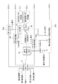
図2は、RRU3の信号処理部32の詳細を示している。RRU3は、一つの送信機40と、一つの受信機50と、を有している。
送信機40は、送信ディジタル信号処理部41、DAC(DAコンバータ)42、変調器43、送信ローカル発振器44,送信アンプ45を備えている。
[2. First Embodiment of RRU]
FIG. 2 shows details of the
The
送信ディジタル信号処理部41は、光I/F31に接続されており、BBU2から送信されてきたディジタル信号(IQ信号)を処理して、DAC42に出力する。DAC42は、ディジタル信号をアナログ信号に変換し、変調器43に出力する。変調器43は、送信ローカル発振器44からの高周波信号を変調し、変調後の信号を送信アンプ45に出力する。送信アンプ45は、信号を増幅し、デュープレクサ46を介して、信号をアンテナ33から出力させる。
The transmission digital
受信機50は、受信ディジタル信号処理部51と、ADC(ADコンバータ)52と、BPF(バンドパスフィルタ)53と、ミキサ54と、受信アンプ56と、を備えている。
アンテナ33にて受信された信号は、デュープレクサ46を介して、受信アンプ56に与えられる。受信アンプ56は、受信信号を増幅し、ミキサ54に出力する。ミキサ54は、受信した信号の周波数を、所定の周波数へ変換する。ミキサ54には、受信ローカル発振器55が接続されている。この受信ローカル発振器55は、ミキサ54が信号を所定の周波数へ変換するために必要とする高周波信号を生成する。
ミキサ54の出力は、BPFを介して、ADC52に与えられる。ADC52は、アナログ信号をディジタル信号に変換し、受信ディジタル信号処理部51に出力する。受信ディジタル信号処理部51は、受信信号を直交復調したIQ信号を光I/F31を介して、BBU2に送信する。
The
A signal received by the antenna 33 is given to the
The output of the
RRU3は、RRU3における動作等を監視する監視制御部(CPU)63を備えている。本実施形態の監視制御部(以下、単に「制御部」という)63は、自律的なDFS機能を有しており、DFSのためにBBU2とRRU3との間で行われる制御が簡素化されている。
DFSを行う無線基地局装置1は、複数の周波数チャネルそれぞれの信号レベルを測定し、その信号レベルが所定の閾値よりも高ければ、他の無線基地局装置が、その周波数チャネルを使用していると判断し、閾値よりも低ければ、その周波数チャネルは空いていると判断する。
The
The radio
DFSのために、RRU3は、前記受信機50におけるアナログ受信信号の信号レベルを検出する検波器(検出部)61を備えている。検波器61によって検出された信号レベルは、ADC62によってディジタル信号に変換され、制御部63に与えられる。
なお、受信信号レベルの検出は、アナログ検波器61で行うことに代えて、受信ディジタル信号処理部51でディジタル的に行っても良い。受信レベルは、信号の包絡線レベル(√(I2+Q2))で得ることができる。
For the DFS, the
The reception signal level may be detected digitally by the reception digital
DFSを行うには、複数の周波数チャネルそれぞれの信号レベルを検出する必要があり、そのため、制御部63は、検波器61が検出する信号の周波数を自律的に決定する機能を有している。検波器61が検出する信号の周波数は、受信ローカル発振器55の周波数を変更することで、変更可能である。制御部63は、受信ローカル発振器55の周波数を、自らが決定した周波数(検出周波数)を生じさせるための周波数に変更するための指示を、受信ローカル発振器55に出力する。その指示を受けた受信ローカル発振器55は、指示に従って、周波数を変更する。
In order to perform DFS, it is necessary to detect the signal level of each of a plurality of frequency channels. For this reason, the
本実施形態の制御部63は、DFSのために検出される信号の周波数を自律的に決定でき、周波数の選択にBBU2からの指示を必要としないため、DFSのためにBBU2とRRU3との間で行われる制御が簡素化されている。
Since the
図3は、RRU2におけるDFS処理(自律的な受信レベル測定処理)の流れを示している。まず、制御部(CPU)63は、空き周波数であるか否かを確認すべき周波数を決定し、決定した周波数に応じて、受信ローカル発振器55の周波数を変更させるための指示を、受信ローカル発振器55に与える(ステップS1)。
FIG. 3 shows a flow of DFS processing (autonomous reception level measurement processing) in RRU2. First, the control unit (CPU) 63 determines a frequency to check whether it is a free frequency, and gives an instruction to change the frequency of the reception
制御部63から周波数変更の指示を受けた受信ローカル発振器55は、その指示に従って、周波数を変更する(ステップS2)。制御部(CPU)63は、受信ローカル発振器55が周波数を変更した後に、検波器61にて検出された受信信号レベルを取得し、図4に示す、受信信号レベルテーブルTに記録する(ステップS3)。受信信号レベルテーブルは、RRUが有する図示しないメモリに保存されている。
The reception
なお、図4の受信信号レベルテーブルTでは、制御部63が、各周波数が空き周波数であるか否かを判断した結果が、「空き」の欄に記録されている。各周波数が、空きであるか否かは、所定の閾値(例えば、−80dBm)と、受信信号レベルと、を比較することで判断される。閾値よりも受信レベルの方が小さければ、「空き」(=1)と判断され、閾値よりも受信レベルの方が大きければ、「空いていない」(=0)と判断される。
各周波数が空きであるか否かの判断は、BBU2側で行っても良いが、本実施形態のように、RRU3側で行うことで、BBU2側の処理負担を軽減できる。
In the received signal level table T of FIG. 4, the result of the
The determination of whether or not each frequency is free may be performed on the BBU2 side, but by performing on the RRU3 side as in the present embodiment, the processing burden on the BBU2 side can be reduced.
そして、BBU2から、受信レベルテーブルTの内容についての問い合わせがあれば(ステップS4)、制御部63は、BBU2へ受信信号レベルテーブルTの内容(検出結果に関する情報)をまとめて送信する処理を行う(ステップS5)。
本実施形態では、制御部63は、BBU2へ受信信号レベルテーブルTの内容をまとめて送信する処理を行うため、受信レベルを検出する度に、BBU2側へその結果を送信する必要がなく、DFSのためにBBU2とRRU3との間で行われる制御が簡素化されている。
また、図3では、BBU2からの問い合わせがあったときに、テーブルTの内容を送信しているが、BBU2からの問い合わせがなくても、RRU3側が自発的にテーブルTの内容を送信してもよい。
If there is an inquiry about the contents of the reception level table T from the BBU 2 (step S4), the
In the present embodiment, the
In FIG. 3, the contents of the table T are transmitted when an inquiry is made from the
BBU2から、受信レベルテーブルTの内容についての問い合わせがなかった場合、又は問い合わせがあった場合には、受信レベルテーブルTの内容の送信が終了すると、制御部63は、次に確認すべき周波数を決定し(ステップS1)、その後の処理を繰り返す。
受信レベルテーブルTは、一旦作成されても、何度も更新されるため、受信レベルテーブルTは、最新の周波数空き情報を示すものとなる。
なお、制御部63は、自律的に周波数を決定する方法としては、例えば、図4のテーブルTに示す周波数の順番(例えば、上から順)で決定することができるが、他の方法(例えば、ランダム)であってもよい。
When there is no inquiry about the contents of the reception level table T from the BBU2, or when there is an inquiry, when the transmission of the contents of the reception level table T is completed, the
Even if the reception level table T is created once, it is updated many times. Therefore, the reception level table T shows the latest frequency vacancy information.
In addition, as a method of determining the frequency autonomously, for example, the
また、空き周波数であるか否かを確認すべき周波数の範囲(探索周波数の範囲)及び/又は、空き周波数であると判断するための受信レベルの閾値は、RRUに予め設定されているが、これらの情報は、BBU2側からRRU3に与えられても良い。
In addition, a frequency range (search frequency range) to be confirmed as to whether or not it is a free frequency and / or a reception level threshold for determining that it is a free frequency is set in advance in RRU. These pieces of information may be given to the
ここで、RRU3が、他の無線基地局装置からの信号を受信するための受信機を、端末装置との本来的な通信のための受信機とは別に備えている場合には、任意のタイミングで、DFSのための受信信号レベル検出を行うことができる。しかし、図2のように、端末装置からの信号を受信するための受信機を、他の無線基地局装置からの受信信号のレベル検出に用いる場合、端末装置との通信周波数とは別の周波数の信号を受信することになる。このため、端末装置からの受信時間の一部で、通常の受信を停止し、周波数を切り換えて、受信信号レベル測定を行う必要がある。
Here, when the
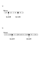
図5(a)は、FDD方式において、端末装置からの信号受信中に、端末装置からの受信を休止して、他の基地局装置からの受信信号レベルの検出を行う「検出区間」のイメージを示し、図5(b)は、TDD方式における「検出区間」のイメージを示している。なお、図5において、「T」は、送信無線フレームを示し、「R」は受信無線フレームを示す。なお、FDD方式では、一つの受信無線フレームR又は一つの送信無線フレームが無線フレームであり、TDD方式では、一つの送信無線フレームTと一つの受信無線フレームRとを連結したものが無線フレームである。図5では、受信無線フレームの後尾の部分を、検出区間として設定している。
制御部63は、この検出区間の開始時点において、受信周波数の切り換えを行い、所望の周波数チャネルで、受信レベルの測定を行い、その後、周波数を、通常の受信周波数チャネルに切り換える。
FIG. 5A shows an image of a “detection interval” in which reception from a terminal apparatus is suspended and a received signal level from another base station apparatus is detected during signal reception from the terminal apparatus in the FDD scheme. FIG. 5B shows an image of a “detection section” in the TDD scheme. In FIG. 5, “T” indicates a transmission radio frame, and “R” indicates a reception radio frame. In the FDD scheme, one reception radio frame R or one transmission radio frame is a radio frame, and in the TDD scheme, a radio frame is a combination of one transmission radio frame T and one reception radio frame R. is there. In FIG. 5, the tail part of the received radio frame is set as a detection section.
The
検出区間の開始タイミング(必要であれば終了タイミングも)は、BBU2からRRU3側へ通知されてもよいが、BBU2の処理負荷を軽減するため、RRU3が自律的に、検出区間のタイミングを把握するのが好ましい。
検出区間が、所定の受信無線フレームの所定の区間であるとして設定されている場合、制御部63は、受信無線フレームのタイミングを把握できれば、設定された検出区間が、実時間において位置するタイミングを把握することができる。
つまり、制御部63は、受信無線フレームのタイミングを特定することで、検出区間のタイミングを特定する。
The start timing of the detection section (and the end timing if necessary) may be notified from the BBU2 to the RRU3 side, but the RRU3 autonomously grasps the detection section timing in order to reduce the processing load of the BBU2. Is preferred.
When the detection section is set as a predetermined section of a predetermined received radio frame, if the
That is, the
検出区間のタイミングの特定は、BBU2とRRU3との間の伝送インターフェースがCPRIである場合、次のように行うことができる。
まず、BBU2とRRU3との間でやり取りされるCPRIフレームは、”CPRI Specification V4.1”<http://www.cpri.info/downloads/CPRI_v_4_1_2009−02−18.pdf>によれば、図6のとおりである。
The detection interval timing can be specified as follows when the transmission interface between the
First, the CPRI frame exchanged between BBU2 and RRU3 is “CPRI Specification V4.1” <http: // www. cpri. info / downloads / CPRI_v_4_1_2009-02-18. According to pdf>, it is as shown in FIG.
CPRIフレームは、1フレームあたり10msの長さを持つ。1個のCPRIフレーム(CPRI10msフレーム)は、150個のハイパーフレームによって構成されている。図6において、Zは、1個のCPRI 10msフレームにおけるハイパーフレームのインデックス(Z=0...149)である。 The CPRI frame has a length of 10 ms per frame. One CPRI frame (CPRI 10 ms frame) is composed of 150 hyperframes. In FIG. 6, Z is a hyperframe index (Z = 0... 149) in one CPRI 10 ms frame.
1個のハイパーフレームは、256個の基本フレームによって構成されている。図6において、Xは、1個のハイパーフレームにおける基本フレームのインデックス(X=0...255)である。 One hyper frame is composed of 256 basic frames. In FIG. 6, X is an index (X = 0... 255) of a basic frame in one hyper frame.
基本フレームは、複数のワードによって構成されている。基本フレームを構成する各ワードは、W=0...15のインデックスを持つ。一つのワードの長さTは、8bit(1バイト)である。なお、CPRIでは、一つのワードの長さTとして、16bit、32bit、40bit、64bit,80bitなども定義されている。
基本フレームにおいて、インデックスW=0である先頭のワードは、制御ワードである。基本フレームの残りのワード(W=1...15)は、ユーザデータ(IQデータ)専用であり、IQデータブロックという。
The basic frame is composed of a plurality of words. Each word constituting the basic frame has W = 0. . . It has 15 indexes. The length T of one word is 8 bits (1 byte). In CPRI, 16-bit, 32-bit, 40-bit, 64-bit, 80-bit, etc. are defined as the length T of one word.
In the basic frame, the first word with index W = 0 is a control word. The remaining words (W = 1... 15) of the basic frame are dedicated to user data (IQ data) and are called IQ data blocks.
一般に、CPRIフレームのような、BBU2とRRU3との間で伝送されるディジタルIQデータフレームは、無線フレームの整数倍(1倍を含む)の時間長さを持ち、無線フレームに対して、一定のオフセット量を持って同期している。
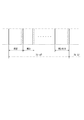
例えば、図7に示すように、CPRIフレームと、LTEの無線フレームとは、ともに長さが10msであり、オフセット量は一定量Δtである。したがって、制御部63は、BBU2から送信されてきたCPRIフレームの境界(先頭)を検出すれば、オフセット量Δtに基づいて、無線フレームの先頭位置を検出できる。無線フレームの先頭位置を検出できれば、受信無線フレーム中において設定された検出区間の実時間位置を特定することができる。
なお、以上のようにして検出された無線フレームのタイミングは、BBU2から送信されてきた送信無線フレームのタイミングであるが、FDD方式の場合、受信無線フレームは、通常、送信無線フレームと一致しているので、受信無線フレームのタイミングを特定したことになる。また、TDD方式の場合、図5(b)に示すように、無線フレーム内で送信無線フレームと受信無線フレームは、所定時間毎に、交互に発生するため、送信無線フレームのタイミングを特定すれば、その所定時間後を、受信無線フレームのタイミングとして特定することができる。
In general, a digital IQ data frame transmitted between BBU2 and RRU3, such as a CPRI frame, has a time length that is an integral multiple (including 1) of a radio frame, and is constant with respect to the radio frame. Synchronized with offset amount.
For example, as shown in FIG. 7, both the CPRI frame and the LTE radio frame are 10 ms in length, and the offset amount is a fixed amount Δt. Therefore, the
Note that the timing of the radio frame detected as described above is the timing of the transmission radio frame transmitted from the
なお、CPRIにおいて、各ハイパーフレームの先頭(Z.X.Y=Z.0.0)には、同期コードK28.5が設けられている。したがって、制御部63は、光I/F31から、CPRIフレームを取得して、この同期コードを検出することで、各ハイパーフレームの先頭を検出できる。そして、ハイパーフレームにおいて、同期コードの次には、ハイパーフレームインデックスZが格納されている。したがって、制御部63は、ハイパーフレームインデックスが0であれば、そのハイパーフレームが、250個のハイパーフレームの先頭(CPRIフレームの先頭)であることを検出できる。
In the CPRI, a synchronization code K28.5 is provided at the head of each hyperframe (ZXY = Z.0.0). Therefore, the
BBU2とRRU3との間の伝送インターフェースがOBSAIである場合もCPRIの場合と同様に行うことができる。例えば、OBSAIは、図8に示すように、10ms周期のマスターフレーム(図8では、「フレーム0」)を持っている。無線通信の規格がWiMAXである場合、無線フレーム長は5msであるので、2個の無線フレームが、マスターフレームに入る。そして、無線フレームとOBSAIの伝送フレームとは、CPRIの場合と同様に、一定のオフセット量をもって同期している。
したがって、制御部63は、CPRIの場合と同様に、マスターフレームの境界を検出すれば、無線フレーム内での検出区間の実時間位置を特定することができる。
The case where the transmission interface between BBU2 and RRU3 is OBSAI can be performed similarly to the case of CPRI. For example, as shown in FIG. 8, OBSAI has a master frame having a period of 10 ms (“
Therefore, similarly to the case of CPRI, the
なお、OBSAIにおいて、マスターフレームは、複数のMG(Massage Group)を有しており、マスターフレームの最後尾には、K28.7という同期コードを持っている。したがって、制御部63は、光I/F31から、OBSAIフレームを取得して、この同期コードを検出することで、OBSAIフレームの境界を検出できる。
In OBSAI, a master frame has a plurality of MGs (Massage Groups), and has a synchronization code of K28.7 at the end of the master frame. Therefore, the
なお、本実施形態では、BBU2からの伝送フレームに基づいて、無線フレームのタイミングを検出したが、受信ディジタル信号処理部51から又はADC52の出力から、受信無線フレームを取得し、受信無線フレームに含まれる同期信号を検出することで、受信無線フレームのタイミングを検出してもよい。
In this embodiment, the timing of the radio frame is detected based on the transmission frame from the
[3.RRUの第2実施形態]
図9は、第2実施形態に係るRRU3を示している。図9のRRU3が、図2のRRU3と異なる点は、受信機(送信機も)を複数備えていること、及び、受信ローカル発振器を複数備えている点である。なお、図9に関して、説明を省略した点は、図2と同様である。
[3. Second Embodiment of RRU]
FIG. 9 shows an
図2のように、RRU3が受信機50を一つしかもっていない場合、他の無線基地局装置からの受信信号レベルの測定は、受信周波数を切り換える必要があるため、通常通信のための受信を休止しなくてはならない。受信の休止によって通信スループットが低下する。しかも、受信を休止しようとすれば、基地局装置1は、端末装置に対して、送信を停止するように通知しなければならない。この通知は、BBU2の通信制御部22が発することになるため、BBU2の処理負荷を大きくする要因となる。
As shown in FIG. 2, when the
図9のRRU3は、受信機50a,50bを2個備えている。これは、マルチアンテナシステム(MIMOなど)に対応して、送受信系統を複数備えたものである。
本実施形態では、マルチアンテナシステムのために複数備わった受信機50a,50bのうちの一部(少なくとも一つ(第2受信機50b))を、端末装置との間で行われる無線通信のほか他の基地局装置からの受信信号レベルの検出にも兼用し、残り(第1受信機50a)を、端末装置との間で行われる通常の無線通信における受信に用いる。
The
In the present embodiment, a part (at least one (
信号レベルの検出に用いる第2受信機50bでは、信号レベルの検出区間においては、受信ディジタル信号処理部51bから出力されるディジタル信号(ベースバンド信号(受信IQ信号))に代えて、ゼロ(無信号を示す値)を出力する。したがって、BBU2へは、検出区間における第2受信機50bの出力信号として、ゼロ値が与えられる。
BBU2では、2系統の受信機50a,50bからの信号を合成して受信処理を行うため、検出区間においても、端末装置との通信を継続できる。すなわち、STC(Space Time Coding)が行われている場合、BBU2にとっては、第2受信機50bからの出力がゼロになっても、単に、第2受信機50bからみた通信環境だけが劣化(例えば、無線伝送路が遮断)した状態と同様である。したがって、第1受信機50aによって端末装置からの信号が受信できていれば、検出区間においても、通信を継続できる。また、BBU2側では、受信した信号のレベルの検出が行われた区間とそうでない区間とを区別する必要がない。したがって、BBU2では、信号レベルの検出区間において、RRU3からの受信IQ信号を遮断する等の処理を行う必要がない。
In the
In BBU2, since reception processing is performed by combining signals from the two
検出区間において第2受信機50bの出力をゼロに設定するため、第2受信機50bは、信号切替部68を備えている。信号切替部68は、第2受信機50bの出力として、受信ディジタル信号処理部51bの出力を選択する場合と、ゼロ値を選択する場合とに、切り替えるためのものである。
信号切替部68には、制御部63から指令(受信IQ切替信号)が与えられる。信号切替部68は、制御部63からの指令に従い、信号レベルの検出区間においては、ゼロ値を出力し、それ以外のときには、受信ディジタル信号処理部51bの出力を出力する。
In order to set the output of the
A command (reception IQ switching signal) is given to the
また、第2実施形態では、受信ローカル発振器として、第1受信ローカル発振器55−1と、第2受信ローカル発振器55−2と、を備えている。第1受信ローカル発振器55−1は、端末装置との間で行われる通常通信用の発振器であり、第2受信ローカル発振器55−2は、他の基地局装置からの受信信号レベル検出用の発振器である。
第1受信ローカル発振器55−1の出力は、分配器65を介して、第1受信機50a及び切替部66に与えられる。切替部は、分配器65を介して与えられた第1受信ローカル発振器55−1からの出力と、第2受信ローカル発振器55−2からの出力と、を選択的に、第2受信機50bに与えるものである。
In the second embodiment, a first reception local oscillator 55-1 and a second reception local oscillator 55-2 are provided as reception local oscillators. The first reception local oscillator 55-1 is an oscillator for normal communication performed with a terminal device, and the second reception local oscillator 55-2 is an oscillator for detecting a received signal level from another base station device. It is.
The output of the first reception local oscillator 55-1 is given to the
切替部66には、制御部63から指令(高周波スイッチ切替信号)が与えられる。切替部66は、制御部63からの指令に従い、信号レベルの検出区間においては、第2受信ローカル発信器55−2からの出力を、第2受信機50bのミキサ54bに与え、それ以外のときには、第1受信ローカル発振器55−1からの出力を、第2受信機50bのミキサ54bに与える。
このように、通常通信用と受信信号レベル検出用の二つの発振器55−1,55−2を設けることで、周波数の切替を迅速に行うことができる。つまり、発振器自体の発振周波数を変更しようとすると、ある程度の時間が必要となり、その分、検出期間が長期化し、通信のスループットの低下を招く。これに対して、検出区間の始まりと終わりにおいて、通常通信用と受信信号レベル検出用の二つの発振器55−1,55−2を切り替えることで、迅速に周波数を変更できる。
A command (high frequency switch switching signal) is given to the
Thus, by providing the two oscillators 55-1 and 55-2 for normal communication and reception signal level detection, the frequency can be switched quickly. In other words, when trying to change the oscillation frequency of the oscillator itself, a certain amount of time is required, and the detection period is increased correspondingly, resulting in a decrease in communication throughput. On the other hand, the frequency can be quickly changed by switching the two oscillators 55-1 and 55-2 for normal communication and reception signal level detection at the beginning and end of the detection interval.
[4.RRUの第3実施形態]
図10は、第3実施形態に係るRRU3を示している。このRRU4では、4つの送受信系統を有するマルチアンテナシステムが採用されている。4つの受信機50a,50b,50c,50dのうち、第4受信機50dが、他の基地局装置からの受信信号レベル測定に用いられる受信機とされている。
第3実施形態の第4受信機50dは、第2実施形態の第2受信機50bと同様の構成であり、第3実施形態の第1〜第3受信機50a,50b,50cは、第2実施形態の第1受信機50aと同様の構成である。
また、第3実施形態において、説明を省略した点については、第2実施形態と同様である。
[4. Third Embodiment of RRU]
FIG. 10 shows an
The
Further, in the third embodiment, points that are not described are the same as in the second embodiment.
なお、今回開示された実施の形態はすべての点で例示であって制限的なものではないと考えられるべきである。本発明の範囲は、上記した意味ではなく、特許請求の範囲によって示され、特許請求の範囲と均等の意味、及び範囲内でのすべての変更が含まれることが意図される。
例えば、上記実施形態では、リモートラジオユニットの受信機として、周波数を1回変換する、いわゆるシングルコンバージョン型の構成を示したが、2回変換するダブルコンバージョン型、3回変換するトリプルコンバージョン型などであってもよい。
The embodiment disclosed this time should be considered as illustrative in all points and not restrictive. The scope of the present invention is defined by the terms of the claims, rather than the meanings described above, and is intended to include any modifications within the scope and meaning equivalent to the terms of the claims.
For example, in the above-described embodiment, a so-called single conversion type configuration in which the frequency is converted once as the receiver of the remote radio unit has been shown, but a double conversion type that converts twice, a triple conversion type that converts three times, and the like There may be.
1 無線基地局装置(無線通信システム)
2 ベースバンドユニット
3 リモートラジオユニット
50,50a,50b,50c,50d 受信機
61 検波器(検出部)
63 制御部
1 Radio base station equipment (wireless communication system)
2
63 Control unit
Claims (8)
前記ベースバンドユニットに接続されたリモートラジオユニットと、
を有し、
前記リモートラジオユニットは、
受信した信号のレベルを検出する検出部と、
前記検出部による信号レベルの検出の処理を行うとともに、前記検出部による検出結果に関する情報を前記ベースバンドユニットに送信する処理を行う制御部と、
を備え、
前記制御部は、前記検出部が検出する信号の周波数を決定するとともに、前記検出部によって検出される信号の周波数を、決定した周波数に切り換える制御を行う
ことを特徴とする無線通信システム。 A baseband unit,
A remote radio unit connected to the baseband unit;
Have
The remote radio unit is
A detection unit for detecting the level of the received signal;
A control unit that performs processing of detecting a signal level by the detection unit and performing processing of transmitting information on a detection result by the detection unit to the baseband unit;
With
The said control part determines the frequency of the signal which the said detection part detects, and performs control which switches the frequency of the signal detected by the said detection part to the determined frequency. The radio | wireless communications system characterized by the above-mentioned.
請求項1記載の無線通信システム。 The wireless communication system according to claim 1, wherein the control unit performs processing of transmitting information indicating availability of each of a plurality of frequencies to the baseband unit as the information related to a detection result by the detection unit.
請求項1又は2記載の無線通信システム。 The wireless communication system according to claim 1, wherein the control unit performs processing of collecting information related to detection results for signals having a plurality of frequencies and transmitting the information to the baseband unit.
請求項1〜3のいずれか1項に記載の無線通信システム。 The wireless communication system according to any one of claims 1 to 3, wherein the control unit specifies a timing of a detection section in which a signal level is to be detected based on a frame timing of a baseband signal from a baseband unit.
請求項1〜3のいずれか1項に記載の無線通信システム。 The wireless communication system according to any one of claims 1 to 3, wherein the control unit specifies timing of a detection section in which a signal level should be detected based on timing of a radio frame received by a remote radio unit. .
請求項1〜5のいずれか1項に記載の無線通信システム。 The remote radio unit includes a plurality of receivers that receive signals for wireless communication, and at least one of the plurality of receivers is also used for signal level detection. The wireless communication system according to item.
請求項1〜6のいずれか1項に記載の無線通信システム。 The remote radio unit includes a receiver that outputs a signal value in a section in which a level of a received signal is detected to a value indicating no signal to the baseband unit side. The wireless communication system according to any one of the above.
受信した信号のレベルを検出する検出部と、
前記検出部による信号レベルの検出の処理を行うとともに、前記検出部による検出結果に関する情報を前記ベースバンドユニットに送信する処理を行う制御部と、
を備え、
前記制御部は、前記検出部が検出する信号の周波数を決定するとともに、前記検出部によって検出される信号の周波数を、決定した周波数に切り換える制御を行う
ことを特徴とするリモートラジオユニット。 A remote radio unit used by connecting to a baseband unit,
A detection unit for detecting the level of the received signal;
A control unit that performs processing of detecting a signal level by the detection unit and performing processing of transmitting information on a detection result by the detection unit to the baseband unit;
With
The remote control unit, wherein the control unit determines a frequency of a signal detected by the detection unit and performs control to switch a frequency of a signal detected by the detection unit to the determined frequency.
Priority Applications (2)
| Application Number | Priority Date | Filing Date | Title |
|---|---|---|---|
| JP2010292965A JP2012142718A (en) | 2010-12-28 | 2010-12-28 | Radio communication system and remote radio unit |
| PCT/JP2011/061866 WO2011148939A1 (en) | 2010-05-27 | 2011-05-24 | Amplifying circuit, wireless communication device, wireless communication system, and remote radio unit |
Applications Claiming Priority (1)
| Application Number | Priority Date | Filing Date | Title |
|---|---|---|---|
| JP2010292965A JP2012142718A (en) | 2010-12-28 | 2010-12-28 | Radio communication system and remote radio unit |
Publications (1)
| Publication Number | Publication Date |
|---|---|
| JP2012142718A true JP2012142718A (en) | 2012-07-26 |
Family
ID=46678578
Family Applications (1)
| Application Number | Title | Priority Date | Filing Date |
|---|---|---|---|
| JP2010292965A Pending JP2012142718A (en) | 2010-05-27 | 2010-12-28 | Radio communication system and remote radio unit |
Country Status (1)
| Country | Link |
|---|---|
| JP (1) | JP2012142718A (en) |
Cited By (3)
| Publication number | Priority date | Publication date | Assignee | Title |
|---|---|---|---|---|
| JP2016533128A (en) * | 2013-09-04 | 2016-10-20 | クアルコム,インコーポレイテッド | Radar detection in wireless networks using frequency division duplex |
| JP2016533132A (en) * | 2013-09-06 | 2016-10-20 | ケーエムダブリュ・インコーポレーテッド | Remote radio equipment |
| JP2017529745A (en) * | 2015-02-26 | 2017-10-05 | 株式会社東芝 | Distributed antenna system with constraints on the average number of active backhaul links |
-
2010
- 2010-12-28 JP JP2010292965A patent/JP2012142718A/en active Pending
Cited By (5)
| Publication number | Priority date | Publication date | Assignee | Title |
|---|---|---|---|---|
| JP2016533128A (en) * | 2013-09-04 | 2016-10-20 | クアルコム,インコーポレイテッド | Radar detection in wireless networks using frequency division duplex |
| US10397793B2 (en) | 2013-09-04 | 2019-08-27 | Qualcomm Incorporated | Radar detection in wireless network that uses frequency-division duplexing |
| JP2016533132A (en) * | 2013-09-06 | 2016-10-20 | ケーエムダブリュ・インコーポレーテッド | Remote radio equipment |
| US9871593B2 (en) | 2013-09-06 | 2018-01-16 | Kmw Inc. | Remote radio head |
| JP2017529745A (en) * | 2015-02-26 | 2017-10-05 | 株式会社東芝 | Distributed antenna system with constraints on the average number of active backhaul links |
Similar Documents
| Publication | Publication Date | Title |
|---|---|---|
| JP7131600B2 (en) | Wireless terminal, wireless station, and methods therefor | |
| US11973711B2 (en) | Electronic apparatus, wireless communication method and computer-readable medium | |
| US9888388B2 (en) | Signaling method for sharing unlicensed spectrum between different radio access technologies and related apparatuses using the same | |
| AU2016350973B2 (en) | Wireless communication device and wireless communication method | |
| WO2019062567A1 (en) | Communication method and apparatus | |
| JP2019531637A5 (en) | ||
| EP3477987A1 (en) | Communication processing method and apparatus in tight coupling between long-term evolution and 5g | |
| EP2665326B1 (en) | Apparatus and method thereof for setting up device-to-device communication | |
| US10972199B2 (en) | RSSI measurement method, network device, and terminal device | |
| JP2012142718A (en) | Radio communication system and remote radio unit | |
| JP2017135620A (en) | Communication relay apparatus, communication relay system, method, and program | |
| WO2011148939A1 (en) | Amplifying circuit, wireless communication device, wireless communication system, and remote radio unit | |
| US9936463B2 (en) | Method for detecting a terminal by a base station, base station, and network entity | |
| US20160080228A1 (en) | Wireless terminal apparatus and wireless communication method | |
| US11425729B2 (en) | Reference signal transmission method and communications device | |
| EP3480974B1 (en) | Method for rssi measurement, network device, and terminal device | |
| EP4084394A1 (en) | Base station apparatus, control method, and program | |
| MX2014000810A (en) | Measurement coordination for dynamic spectrum access measurements in a time division duplex system. | |
| US8559916B2 (en) | Communication system and radio processing apparatus | |
| EP3869870A1 (en) | Signal processing method, device and base station | |
| CN113973353A (en) | Electronic device, wireless communication method, and computer-readable storage medium | |
| CN111669203A (en) | Joint decoding method and related equipment |