JP6514624B2 - Obstacle detection device - Google Patents
Obstacle detection device Download PDFInfo
- Publication number
- JP6514624B2 JP6514624B2 JP2015215752A JP2015215752A JP6514624B2 JP 6514624 B2 JP6514624 B2 JP 6514624B2 JP 2015215752 A JP2015215752 A JP 2015215752A JP 2015215752 A JP2015215752 A JP 2015215752A JP 6514624 B2 JP6514624 B2 JP 6514624B2
- Authority
- JP
- Japan
- Prior art keywords
- obstacle
- vehicle
- area
- parking space
- camera
- Prior art date
- Legal status (The legal status is an assumption and is not a legal conclusion. Google has not performed a legal analysis and makes no representation as to the accuracy of the status listed.)
- Active
Links
Images


Classifications
-
- G—PHYSICS
- G08—SIGNALLING
- G08G—TRAFFIC CONTROL SYSTEMS
- G08G1/00—Traffic control systems for road vehicles
- G08G1/16—Anti-collision systems
- G08G1/168—Driving aids for parking, e.g. acoustic or visual feedback on parking space
-
- G—PHYSICS
- G06—COMPUTING; CALCULATING OR COUNTING
- G06V—IMAGE OR VIDEO RECOGNITION OR UNDERSTANDING
- G06V20/00—Scenes; Scene-specific elements
- G06V20/50—Context or environment of the image
- G06V20/56—Context or environment of the image exterior to a vehicle by using sensors mounted on the vehicle
- G06V20/58—Recognition of moving objects or obstacles, e.g. vehicles or pedestrians; Recognition of traffic objects, e.g. traffic signs, traffic lights or roads
- G06V20/586—Recognition of moving objects or obstacles, e.g. vehicles or pedestrians; Recognition of traffic objects, e.g. traffic signs, traffic lights or roads of parking space
-
- B—PERFORMING OPERATIONS; TRANSPORTING
- B60—VEHICLES IN GENERAL
- B60R—VEHICLES, VEHICLE FITTINGS, OR VEHICLE PARTS, NOT OTHERWISE PROVIDED FOR
- B60R21/00—Arrangements or fittings on vehicles for protecting or preventing injuries to occupants or pedestrians in case of accidents or other traffic risks
-
- B—PERFORMING OPERATIONS; TRANSPORTING
- B62—LAND VEHICLES FOR TRAVELLING OTHERWISE THAN ON RAILS
- B62D—MOTOR VEHICLES; TRAILERS
- B62D15/00—Steering not otherwise provided for
- B62D15/02—Steering position indicators ; Steering position determination; Steering aids
- B62D15/027—Parking aids, e.g. instruction means
-
- G—PHYSICS
- G06—COMPUTING; CALCULATING OR COUNTING
- G06V—IMAGE OR VIDEO RECOGNITION OR UNDERSTANDING
- G06V20/00—Scenes; Scene-specific elements
- G06V20/50—Context or environment of the image
- G06V20/56—Context or environment of the image exterior to a vehicle by using sensors mounted on the vehicle
- G06V20/58—Recognition of moving objects or obstacles, e.g. vehicles or pedestrians; Recognition of traffic objects, e.g. traffic signs, traffic lights or roads
-
- G—PHYSICS
- G08—SIGNALLING
- G08G—TRAFFIC CONTROL SYSTEMS
- G08G1/00—Traffic control systems for road vehicles
- G08G1/14—Traffic control systems for road vehicles indicating individual free spaces in parking areas
- G08G1/141—Traffic control systems for road vehicles indicating individual free spaces in parking areas with means giving the indication of available parking spaces
-
- G—PHYSICS
- G08—SIGNALLING
- G08G—TRAFFIC CONTROL SYSTEMS
- G08G1/00—Traffic control systems for road vehicles
- G08G1/16—Anti-collision systems
-
- G—PHYSICS
- G08—SIGNALLING
- G08G—TRAFFIC CONTROL SYSTEMS
- G08G1/00—Traffic control systems for road vehicles
- G08G1/16—Anti-collision systems
- G08G1/166—Anti-collision systems for active traffic, e.g. moving vehicles, pedestrians, bikes
Landscapes
- Engineering & Computer Science (AREA)
- Physics & Mathematics (AREA)
- General Physics & Mathematics (AREA)
- Multimedia (AREA)
- Theoretical Computer Science (AREA)
- Mechanical Engineering (AREA)
- Chemical & Material Sciences (AREA)
- Combustion & Propulsion (AREA)
- Transportation (AREA)
- Traffic Control Systems (AREA)
- Image Analysis (AREA)
- Control Of Driving Devices And Active Controlling Of Vehicle (AREA)
Description
本発明は、障害物検知装置に関する。 The present invention relates to an obstacle detection device.
自動車の駐車支援において、目標とした位置に自動車を移動させるだけでなく、障害物への衝突を避けるために障害物を検知することが求められる。特許文献1には、駐車区画に対して所定の位置関係を有するマークが設置され、撮影したこのマークの画像に基づき車両が目標初期停止位置に停止しているか否かを判断し、目標初期停止位置に停止していると判断すると、障害物の有無を検知する駐車支援装置が開示されている。
In parking assistance of a car, in addition to moving the car to a target position, it is required to detect an obstacle in order to avoid a collision with the obstacle. In
特許文献1に記載されている発明では、所定の位置に停止し障害物の有無の検知を開始した以後は算出処理の削減が考慮されていないため、障害物情報の算出処理が膨大になる。
In the invention described in
本発明の第1の態様による障害物検知装置は、移動する車両に搭載され当該車両の前方または後方を撮影する第1カメラと、前記車両に搭載され前記車両の側方を撮影する第2カメラと、前記第1カメラが撮影して得られた画像に基づき前記車両の駐車スペースを検出する駐車スペース検出部と、前記駐車スペース検出部が検出する前記駐車スペースの前記車両に対する実空間上の領域を示す情報を記憶する記憶部と、前記車両の挙動に関する情報を取得する車両運動取得部と、前記第2カメラが異なる時刻に撮影して得られた複数の画像に基づき前記駐車スペースの周辺に存在する障害物を検出する障害物検出部と、前記記憶部に記憶された前記駐車スペースの前記車両に対する実空間上の領域、および前記車両運動取得部が取得する前記車両の挙動に関する情報に基づき、前記車両の位置と前記駐車スペースの前記車両に対する実空間上の領域が所定の条件を満たした場合に前記障害物検出部に障害物の検出を行わせる処理領域設定部とを備える。 An obstacle detection device according to a first aspect of the present invention is a first camera mounted on a moving vehicle for photographing the front or the rear of the vehicle, and a second camera mounted on the vehicle for photographing the side of the vehicle A parking space detection unit that detects a parking space of the vehicle based on an image obtained by shooting by the first camera; and an area of the parking space in the real space with respect to the vehicle of the parking space that is detected by the parking space detection unit. And a vehicle motion acquisition unit that acquires information on the behavior of the vehicle, and the periphery of the parking space based on a plurality of images obtained by photographing the second camera at different times. wherein in which the obstacle detecting unit for detecting an obstacle present, the area in the real space relative to the vehicle of the parking space stored in the storage unit, and the vehicle motion acquisition unit acquires Based on the information on the behavior of both, position and the detected processing region setting to perform obstacle to the obstacle detection unit when the area in the real space satisfies a predetermined condition with respect to the vehicle of the parking space of the vehicle And a unit.
本発明によれば、障害物情報の算出による処理負荷を軽減することができる。 According to the present invention, the processing load due to the calculation of obstacle information can be reduced.
(第1の実施の形態)
以下、図1〜図7を参照して、障害物検知装置の第1の実施の形態を説明する。
(構成)
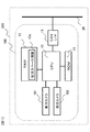
図1は車両500に内蔵される障害物検知装置100の構成を示す図である。車両500はCANバス20を備えており、障害物検知装置100はCANバス20に接続される。CANバス20には不図示の他の機器も接続されている。すなわち、CANバス20に車両の進行方向を出力する装置や、CANバス20に車両の速度を出力する装置、さらに
障害物検知装置100が出力する障害物情報に基づき車両500を制御する装置が接続される。
First Embodiment
Hereinafter, a first embodiment of the obstacle detection device will be described with reference to FIGS. 1 to 7.
(Constitution)
FIG. 1 is a diagram showing the configuration of an
障害物検知装置100は、前方カメラ101と、側方カメラ102と、CPU10と、ROM11と、RAM12と、CANインタフェース13とを備える。
前方カメラ101は、車両500の上部前方に取り付けられ、車両500の前方を撮影する。側方カメラ102は、車両500の左側面に取り付けられ、車両500の左側方を撮影する。
The
The
CPU10は、予め定められた周期ごと、たとえば0.1秒ごとに、後述するプログラムを用いて前方カメラ101および側方カメラ102が撮影して得られた画像から障害物情報を算出する。算出した障害物情報は、CANインタフェース13を介してCANバス20に出力される。以下では、上述した予め定められた周期を「処理周期」と呼ぶ。
ROM11には、プログラムと、前方カメラ101および側方カメラ102のカメラパラメータとが記憶される。プログラムは、CPU10によりROM11からRAM12に展開されて実行される。カメラパラメータとは、レンズ歪等の内部パラメータおよび車両に対するカメラ取り付け位置・角度等の外部パラメータである。RAM12には、駐車スペース情報領域12a、あるいはプログラムの実行に必要なその他の情報が一時的に保存される。駐車スペース情報領域12aについては後述する。
The
The
CANインタフェース13は、障害物検知装置100のCANバス20との通信インタフェースである。障害物検知装置100は、CANインタフェース13を介して車両500の運動情報、すなわち車両500の進行方向および速度に関する情報を取得する。障害物検知装置100は、算出した障害物情報をCANインタフェース13を介してCANバス20に出力する。
The
(駐車スペース情報領域)
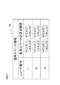
駐車スペース情報領域12aは、後述する駐車スペース検知部103が検知した駐車スペースに関する情報が保存されるRAMの所定領域である。駐車スペースに関する情報とは、自車両に対する実空間上の駐車スペースの位置および姿勢である。出力する駐車スペースの位置および姿勢は、たとえば駐車スペースを構成する複数の頂点座標の組み合わせとして表される。あるいは、駐車スペースの中心座標、駐車スペースの大きさ、および自車両に対する駐車スペースの傾きの組み合わせとして表してもよい。
図2は駐車スペース情報領域12aの一例を示す図である。図2に示す例では、駐車スペース情報領域12aには、3レコード、すなわち3つの駐車スペースに関する情報が保存されている。この例では駐車スペースを、駐車スペースを構成する複数の頂点座標の組み合わせとして表現している。この座標は、自車両を中心とした座標系、すなわち相対位置を表している。
(Parking space information area)
The parking
FIG. 2 is a view showing an example of the parking
(機能ブロック)
図3は、障害物検知装置100のCPU10において実行されるプログラムが有する機能を機能ブロックとして表した図である。すなわち、障害物検知装置100は、CPU10において実行されるプログラムにより、駐車スペース検知部103による駐車スペース検知機能と、車両運動取得部104による車両運動取得機能と、処理領域設定部105による処理領域設定機能と、側方障害物検知部106による側方障害物検知機能と、出力部107による出力機能とを備える。障害物検知装置100は、予め定められた周期、すなわち処理周期ごとに前方カメラ101および側方カメラ102に撮影を行わせ、撮影して画像が得られると各機能ブロックによる処理を行う。具体的には、前方カメラ101が撮影を行い画像が得られると駐車スペース検知部103が処理を開始し、駐車スペース検知部103が処理を完了すると処理領域設定部105が処理を開始し、処理領域設定部105が処理を完了すると側方障害物検知部106が処理を開始する。すなわち、各機能ブロックは処理周期ごとに動作する。
(Function block)
FIG. 3 is a view representing, as a functional block, a function that a program executed in the
駐車スペース検知部103は、前方カメラ101が撮影して得られた画像から自車両前方に存在する駐車スペースを検知し、検知した駐車スペースに関する情報を駐車スペース情報領域12aに追加する。駐車スペースの検知とは、例えば、画像から白線を検出し、2つの白線の間の領域を駐車スペースとして検知するものである。もしくは、画像から障害物を検出し、障害物が存在しない領域を駐車スペースとするものである。障害物の検出には、後述する側方障害物検知部106と同様の処理を用いることができる。
The parking
車両運動取得部104は、CANインタフェース13を介して車両500の運動に関する情報、すなわち車両500の進行方向や速度に関する情報を取得する。そして、前回の処理周期から現在の処理周期までの車両500の移動量を算出し、処理領域設定部105に出力する。車両500の運動情報は、車両500に取り付けられた車輪の回転量を取得するホイールエンコーダと操舵角からそれぞれ出力される情報をCANバス20経由で取得される。これらの情報に基づき車両の幾何モデルに従った計算を実行することにより、車両の移動量、たとえば右に2m、前方に0.5mなどが算出される。もしくは、車両500に搭載された加速度・角加速度計やGPSなど、姿勢・位置情報を取得可能なセンサの出力値をCANバス20を経由して取得し、車両の移動量を計算するようにしてもよい。
The vehicle
処理領域設定部105は、後段の処理である側方障害物検知部106が処理対象とする、画像上の領域である処理領域Cを設定する。処理領域Cは、駐車スペース検知部103が出力してRAM12の駐車スペース情報領域12aに保存されている情報、および車両運動取得部104の出力、すなわち車両の運動情報に基づき設定される。後述するように、処理領域Cが空白、すなわち処理領域Cが存在しないと設定されている場合には、側方障害物検知部106は処理を行わない。
The processing area setting
側方障害物検知部106は、側方カメラ102が異なる時刻に撮影して得られた複数の画像に対して、以下の処理を行う。すなわち、現在の処理周期において得られた画像において、上述したように設定された処理領域Cを特定し、それらの処理領域Cに含まれる、輝度を含む画像情報と、過去の処理周期において得られた画像に含まれる、輝度を含む画像情報とを用いて、自車両側方に存在する障害物を検知し、障害物との相対位置を出力する。処理領域設定部105により処理領域Cが空白に設定されている場合は、側方障害物検知部106は処理を行わない。処理の詳細は後述する。
出力部107は、障害物検知結果をCANインタフェース13を介してCANバス20へ出力する。
The side
The
(処理領域設定部の動作)
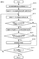
次に図4〜図6を用いて、処理領域設定部105における処理の内容について説明する。図4は処理領域設定部105において実行される処理を示すフローチャートである。以下に説明する各ステップの実行主体は、CPU10である。
ステップS210では、処理領域Cをクリアし、処理領域Cを空白とする。これにより、後述するステップS216で処理領域Cが設定されない限り、側方障害物検知部106は三次元位置の算出を行わない。次にステップS211に進む。
(Operation of processing area setting unit)
Next, the contents of processing in the processing
In step S210, the processing area C is cleared and the processing area C is made blank. Thus, the side
ステップS211では、RAM12の駐車スペース情報領域12aに保存されている情報を、車両運動取得部104により出力された直前の処理周期から現在の処理周期までの車両の移動量を用いて更新する。ただし、現在の処理周期において駐車スペース検知部103により検知された駐車スペースは、駐車スペース検知部103が出力した駐車スペースに関する情報をそのまま用いる。次にステップS212に進む。次のステップS212以降の処理は、駐車スペース情報領域12aに保存されている駐車スペースのそれぞれに対して繰り返される。ステップS212が初回に実行される際は、駐車スペース情報領域12aに保存されている先頭のレコードが処理される。
ステップS212では、駐車スペースと自車両の相対位置・姿勢から、駐車スペースと自車両との距離dを計算し、ステップS213に進む。
In step S211, the information stored in the parking
In step S212, the distance d between the parking space and the vehicle is calculated from the relative position and posture of the parking space and the vehicle, and the process proceeds to step S213.
図5は駐車スペースと自車両の距離dの一例を示す図である。自車両周辺には、白線502の間に駐車された駐車車両501が存在している。また、駐車スペース検知部103により駐車スペース503が検知されている。駐車スペース503の位置を駐車スペースにおける自車両500に最も近い位置と定義し、自車両の位置を側方カメラ102の位置と定義する。駐車スペース503の位置と自車の位置との距離504を計算し、これを距離dとする。
ここで、本例においては、自車両の位置として左カメラの位置を用いたが、自車両の位置はこれに限定されるものではなく、例えば、自車両の中心でもよい。また、駐車スペースの位置として、自車両に最も近い位置を用いたが、駐車スペースの位置はこれに限定されるものではなく、例えば、駐車スペースの中心でもよい。
FIG. 5 is a view showing an example of the distance d between the parking space and the vehicle. A parked
Here, in the present embodiment, the position of the left camera is used as the position of the host vehicle, but the position of the host vehicle is not limited to this, and may be, for example, the center of the host vehicle. Also, although the position closest to the host vehicle is used as the position of the parking space, the position of the parking space is not limited to this, and may be, for example, the center of the parking space.
図4に戻ってフローチャートの説明を続ける。
ステップS213では、駐車スペースと自車両の距離dがあらかじめ設定された閾値d_th以下か否かを判断する。距離dが閾値d_th以下であると判断する場合にはステップS214に進み、距離dが閾値d_thより大きいと判断する場合にはステップS217に進む。
ステップS214では、側方カメラ102により撮影して得られた画像において、駐車スペースおよび駐車スペース周辺が映ると予想される領域である予測領域Pを計算する。予測領域Pは、駐車スペースと自車両の相対位置・姿勢と側方カメラ102の外部・内部パラメータとを用いて、透視投影モデルなどに従った投影計算により求めることができる。次にステップS215に進む。
Returning to FIG. 4, the description of the flowchart is continued.
In step S213, it is determined whether the distance d between the parking space and the vehicle is equal to or less than a predetermined threshold d_th. If it is determined that the distance d is equal to or less than the threshold d_th, the process proceeds to step S214. If it is determined that the distance d is larger than the threshold d_th, the process proceeds to step S217.
In step S214, in the image obtained by photographing with the
ステップS215では、ステップS214において算出した予測領域Pの全域が、あらかじめ設定された判定領域A内に存在するか否かを判断する。判定領域Aは次のように定義する。側方カメラ102により撮影して得られた画像の周辺部分は歪が大きい。そのため、画像の周辺部を除いた領域を判定領域Aとしている。予測領域Pの全域が判定領域A内に存在すると判断する場合にはステップS216に進む。予測領域Pの一部が判定領域A内に存在しない、または予測領域Pと判定領域Aが全く重複しないと判断する場合にはステップS217に進む。
In step S215, it is determined whether the entire area of the prediction area P calculated in step S214 exists in the determination area A set in advance. The judgment area A is defined as follows. The peripheral portion of the image obtained by photographing with the
図6は、予測領域Pと判定領域Aの一例を示す図である。本例では、側方カメラ102によって撮影されて得られた画像510には、駐車車両511と白線512が映っている。ステップS214では、駐車スペースおよび駐車スペース周辺が映ると予想される領域である予測領域Pが投影計算により計算される。ステップS215では、予測領域Pが予め設定された判定領域A内に存在するか否かを判定する。図6に示す例では、予測領域Pの全域が判定領域A内に存在するため、ステップS216に進むこととなる。図4に戻って説明を続ける。
FIG. 6 is a diagram illustrating an example of the prediction area P and the determination area A. In this example, the parked
ステップS216では、ステップS214において計算された予測領域Pを処理領域Cとして設定する。ここで、駐車スペースの検知位置や車両の移動量、キャリブレーションの誤差を考慮し、予測領域Pより広い領域を処理領域Cとして設定してもよい。次にステップS217に進む。
ステップS217では、RAM12の駐車スペース情報領域12aに保存されている情報全てのレコードが処理されたか否かを判断する。全てのレコードが処理されたと判断する場合は図4のフローチャートにより表される処理を終了し、未処理のレコードが残っていると判断する場合はステップS212に戻る。
たとえば、駐車スペース情報領域12aに複数のレコードが保存されている場合は、これらに対応するそれぞれの予測領域Pが算出され、それらの全てを合せた領域が処理領域Cに設定される場合もある。
In step S216, the prediction area P calculated in step S214 is set as the processing area C. Here, an area wider than the prediction area P may be set as the processing area C in consideration of the detection position of the parking space, the movement amount of the vehicle, and the calibration error. Next, the process proceeds to step S217.
In step S217, it is determined whether the record of all the information stored in the parking
For example, when a plurality of records are stored in the parking
(側方障害物検知部の動作)
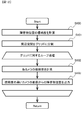
図7を用いて、側方障害物検知部106における処理の内容について説明する。
図7は側方障害物検知部106において実行される処理を示すフローチャートである。側方障害物検知部106では、側方カメラ102が撮影して得られた画像、および処理領域設定部105において設定された処理領域Cに基づき側方障害物の三次元位置を計算する。以下に説明する各ステップの実行主体は、CPU10である。
(Operation of side obstacle detection unit)
The contents of processing in the side
FIG. 7 is a flowchart showing the process executed by the side
ステップS200では、処理領域Cが存在するか否かを判断する。側方障害物検知部106において、ステップS210により処理領域Cがクリアされた後に1度もステップS216が実行されなかった場合には、処理領域Cが存在しないこととなる。処理領域Cが存在すると判断する場合はステップS201に進み、処理領域Cが存在しないと判断する場合は図7に示すフローチャートにより表される処理を終了する。
In step S200, it is determined whether the processing area C exists. In the side
ステップS201では、現在の処理周期において側方カメラ102が撮影して得られた画像であって、処理領域Cに含まれる領域から特徴点を抽出する。本ステップにおいて抽出した特徴点は、次のステップにおいて用いられる。特徴点の抽出はたとえば、画像から周囲の点との差が大きく対応付けが容易な点(特徴点)を、コーナーやエッジ上から抽出するハリスコーナ検出法(C. Harris and M. Stephens: “A combined corner and edge detector,” Proc. Alvey Vision Conf., pp. 147-151, 1988.)を用いることができる。次にステップS202に進む。
In step S201, feature points are extracted from an area included in the processing area C, which is an image obtained by photographing by the
ステップS202では、ステップS201において抽出された特徴点に対応する点をn周期前の側方カメラ102の画像から探索する。nにはあらかじめ任意の値を設定する。もしくは、車両運動取得部104から得られる車両の移動量に応じ、あらかじめ設定された距離の移動に要した周期を設定してもよい。
n周期前の側方カメラ102の画像から対応する点が探索されると、その点が障害物であると判断する。
In step S202, a point corresponding to the feature point extracted in step S201 is searched from the image of the side camera 102 n cycles earlier. An arbitrary value is set in advance to n. Alternatively, in accordance with the amount of movement of the vehicle obtained from the vehicle
When a corresponding point is searched from the image of the side camera 102 n cycles earlier, it is determined that the point is an obstacle.
ここで、車両の移動前後で取得された時間的に連続な画像間では、特徴点の画像中での位置は大きく変化しないと考えられる。そこで、特徴点が抽出された位置の周囲を探索することで、効率的な探索を行うことができる。単純には、特徴点が抽出された位置を中心とした一定範囲内を探索範囲に設定し、探索を行う。探索には、特徴点の位置を中心とした近傍の画像パターンを用い、探索範囲内で画像パターンに最も類似したパターンを探索する。類似度の尺度としては、SSD(Sum of Squared Difference)やSAD(Sum of Absolute Difference)、NCC(正規化相互相関)などを用いることができる。 Here, it is considered that the position of the feature point in the image does not change significantly between the temporally continuous images acquired before and after the movement of the vehicle. Therefore, efficient search can be performed by searching around the position where the feature point is extracted. In a simple manner, the search is performed by setting a predetermined range around the position where the feature point is extracted as the search range. In the search, a pattern closest to the image pattern in the search range is searched using a nearby image pattern centered on the position of the feature point. As a measure of similarity, sum of squared difference (SSD), sum of absolute difference (SAD), or NCC (normalized cross correlation) can be used.
また、探索範囲を設定する代わりに、特徴点の抽出位置を初期値とし、繰り返し計算により、初期値近傍でSSD値が小さくなる点を探索するLK法(Bruce D. Lucas and Takeo Kanade. An Iterative Image Registration Technique with an Application to Stereo Vision. Int. Joint Conf. on Artificial Intelligence, pp. 674-679, 1981.)を用いることができる。LK法は画像間の動きが小さい場合に高速・高精度に対応付けを得ることができ、移動体により撮影された時間的に連続した画像間の対応付けに適している。 Also, instead of setting the search range, the LK method uses the extraction position of the feature point as an initial value and searches for a point at which the SSD value decreases near the initial value by iterative calculation (Bruce D. Lucas and Takeo Kanade. An Iterative Int. Joint Conf. On Artificial Intelligence, pp. 674-679, 1981.) can be used. The LK method can obtain association at high speed with high accuracy when the motion between images is small, and is suitable for association between temporally consecutive images captured by a moving object.
ステップS203では、ステップS202において対応付けられた特徴点の三次元位置を計算する。特徴点の三次元位置は、現在の処理周期およびn周期前の処理周期における画像中での特徴点の位置と、側方カメラ102の内部パラメータと、n周期間における側方カメラ102の移動量とを用いて、三角測量の原理に基づき計算することができる。
ここで、側方カメラ102の移動量は、車両運動取得部104により取得される車両の移動量と、側方カメラ102の車両に対する取り付け位置・角度から計算することができる。もしくは、特徴点の対応付け結果とカメラ内部パラメータからカメラの相対位置・姿勢を計算するSfM(Structure from Motion)法を適用してもよい。
In step S203, the three-dimensional position of the feature point associated in step S202 is calculated. The three-dimensional position of the feature point is the position of the feature point in the image at the current processing cycle and the processing cycle n cycles earlier, the internal parameters of the
Here, the movement amount of the
ステップS203の処理により、側方障害物検知部106は、三次元点群として側方障害物を検知する。また、例えば、得られた三次元点群において、距離が近い点同士を結合することで、側方障害物としてもよい。ただし、検出された障害物の高さが所定値以下である場合には、車両の走行の妨げとならないため障害物から除外してもよい。
以上により、図5に示すフローチャートにより表される処理を終了する。
By the process of step S203, the side
Thus, the process represented by the flowchart shown in FIG. 5 is ended.
上述した第1の実施の形態によれば、次の作用効果が得られる。
(1)障害物検知装置100は、移動する車両500に搭載され当該車両の前方を撮影する第1カメラ、すなわち前方カメラ101と、車両500に搭載され車両の左側方を撮影する第2カメラ、すなわち側方カメラ102と、第1カメラが撮影して得られた画像に基づき当該車両の駐車スペースを検出する駐車スペース検知部103と、駐車スペース検知部103が検出する駐車スペースの実空間上の領域を駐車スペース情報領域12aに記憶する記憶部、すなわちRAM12と、車両500の挙動に関する情報を取得する車両運動取得部104と、側方カメラ102が異なる時刻に撮影して得られた複数の画像に基づき駐車スペースの周辺に存在する障害物の情報を算出する障害物算出部、すなわち側方障害物検知部106と、記憶部に記憶された駐車スペースの実空間上の領域、および運動取得部が取得する車両500の運動に関する情報に基づき、障害物算出部における算出を制御する処理領域設定部105とを備える。
障害物検知装置100では、前方カメラ101が撮影して得られた画像から検出される駐車スペースと、車両500の並進や回転に関する車両運動情報とに基づき、処理領域設定部105が側方障害物検知部106を制御するようにした。そのため、側方障害物検知部106で行われる障害物情報の算出による処理負荷を軽減することができる。
According to the first embodiment described above, the following effects can be obtained.
(1) The
In the
(2)処理領域設定部105は、記憶部に記憶された駐車スペースの実空間上の領域、および運動取得部が取得する車両の挙動に関する情報に基づき、駐車スペースと車両500との実空間上の距離を算出し、距離が予め定められた距離よりも遠い場合に障害物算出部に障害物情報の算出処理を行わせないと決定する(図4、ステップS213)。
そのため、側方カメラ102と駐車スペースとの距離が遠い場合には、処理領域Cを設定しないことにより側方障害物検知部106に障害物算出の演算を行わせず(図7、ステップS200:NO)、障害物情報の算出処理を削減することができる。これは、側方カメラ102と駐車スペースとの距離が遠い場合には、側方カメラ102で撮影して得られた画像には駐車スペースが小さくしか撮影されず、このような画像を用いて障害物情報を算出することは困難、または算出できても精度が低いと考えられるからである。
(2) On the real space of the parking space and the
Therefore, when the distance between the
(3)処理領域設定部105は、記憶部に記憶された駐車スペースの実空間上の領域、および車両運動取得部104が取得する車両500の運動に関する情報に基づき、側方カメラ102が撮影して得られる画像における駐車スペースの領域、すなわち予測領域Pを算出し、予測領域Pと、画像内の予め定められた判定領域Aとの関係に基づき障害物算出部に算出を行わせるか否かを決定する(図4、ステップS215)。
そのため、側方カメラ102が撮影して得られた画像において、周辺部を除いた領域を判定領域Aに設定しているので、予測領域Pが判定領域Aに含まれない場合は処理領域Cを設定せず、障害物情報の算出処理を削減することができる。
(3) The processing
Therefore, in the image obtained by photographing by the
(4)処理領域設定部105は、第2カメラが撮影して得られる画像における駐車スペースの領域、すなわち予測領域Pの少なくとも一部が判定領域Aに含まれる場合に、第2カメラが撮影して得られた画像において判定領域Aに含まれる領域を処理領域Cに設定する。処理領域設定部105は、処理領域Cに含まれる、輝度などを含む画像情報を用いて、側方障害物検知部106に算出を行わせる。
そのため、歪みの小さい判定領域Aに含まれる画像を用いて側方障害物検知部106が障害物情報を算出するので、精度の高い障害物情報を得ることができる。
(4) The processing
Therefore, the side
(5)処理領域設定部105は、第2カメラが撮影して得られる画像における駐車スペースの領域、すなわち予測領域Pの少なくとも一部が判定領域Aに含まれる場合に、第2カメラが撮影して得られた画像において、判定領域Aと予測領域Pとが重複する領域を処理領域Cに設定する。処理領域設定部105は、処理領域Cに含まれる、輝度を含む画像情報を用いて、側方障害物検知部106に算出を行わせる。
そのため、歪みが小さい領域にあり、なおかつ情報を得たい対象である駐車スペースが撮影されている領域のみを処理領域Cに設定するので、障害物情報の算出処理を削減しつつ精度の高い障害物情報を得ることができる。
(5) The processing
Therefore, the processing area C is set only in the area where the distortion is small and the parking space for which information is desired to be obtained is taken as the processing area C. Therefore, the obstacle information calculation process is reduced and the obstacle with high accuracy is obtained. You can get information.
(変形例1)
上述した第1の実施の形態では、車両500の前方および左側方にカメラが取り付けられた。しかし、カメラの台数およびカメラの取付け位置はこれに限定されない。
障害物検知装置100は、車両500の前方を撮影する前方カメラ101の代わりに車両500の後方を撮影するカメラを備えてもよいし、前方カメラ101に加えて車両500の後方を撮影するカメラを備えてもよい。
前方カメラ101に代えて車両500の後方を撮影するカメラを備える場合は、前方カメラ101が撮影して得られた画像の代わりに車両500の後方を撮影するカメラが撮影して得られた画像を用いて第1の実施の形態において説明した処理を行う。
(Modification 1)
In the first embodiment described above, the camera is attached to the front and the left side of the
The
When the camera for capturing the back of the
前方カメラ101に加えて車両500の後方を撮影するカメラを備える場合は、それぞれのカメラで撮影して得られた画像に対して個別に第1の実施の形態において説明した処理を行ってもよい。さらに、車両500の進行方向により使い分けて、車両500の前進時には前方カメラ101が撮影して得られた映像を用い、車両500の後退時には車両500の後方を撮影するカメラが撮影して得られた画像を用いてもよい。この変形例を実現するためには、次の機能を障害物検知装置100に付加する必要がある。たとえば、車両前後進を判定する機能と、判定結果である前進か後進かによって、障害物検出対象画像を前方画像と後方画像との間で切り替える機能である。
When a camera for capturing the rear of the
さらに、障害物検知装置100は、車両500の左側方を撮影する側方カメラ102の代わりに車両500の右側方を撮影するカメラを備えてもよいし、側方カメラ102に加えて車両500の右側方を撮影するカメラを備えてもよい。側方カメラ102と車両500の右側方を撮影するカメラとの使い分けは、上述した前方カメラ101と車両500の後方を撮影するカメラとの使い分けと同様である。この変形例を実現するためには、次の機能を障害物検知装置100に付加する必要がある。たとえば、前方カメラ画像もしくは後方画像を用いて、車両左右のどちら側に駐車スペースが存在するかを判定する機能と、判定結果である駐車スペースの存在方向によって、障害物検出対象画像を右方画像と左方画像との間で切り替える機能である。
Furthermore, the
(変形例2)
上述した第1の実施の形態では、障害物検知装置100は車両500のCANバス20を介して他の機器と接続された。しかし、障害物検知装置100の他の機器との接続関係はこれに限定されない。
障害物検知装置100はCAN以外の通信バスを介して他の機器と接続されてもよいし、通信バスを介さずに直接他の機器と接続されてもよい。さらに、障害物検知装置100がカメラ装置または統合コントローラ内などに組み込まれてもよい。
(Modification 2)
In the first embodiment described above, the
The
(変形例3)
処理領域設定部105は、予測領域Pの全域が判定領域A内に存在する場合に、予測領域Pを処理領域Cとして設定した(図4、ステップS215:YES、ステップS216)。しかし処理領域Cの設定方法はこれに限定されない。
処理領域設定部105は、予測領域Pの全域が判定領域A内に存在する場合に、判定領域Aの全体を処理領域Cに設定してもよいし、側方カメラ102が撮影して得られた画像の全域を処理領域Cに設定してもよい。
処理領域設定部105は、予測領域Pの少なくとも一部が判定領域A内に存在する場合に、予測領域Pを処理領域Cとして設定してもよいし、判定領域Aを処理領域Cとして設定してもよいし、判定領域Aと予測領域Pとが重複する領域を処理領域Cとして設定してもよいし、側方カメラ102が撮影して得られた画像の全域を処理領域Cに設定してもよい。
(Modification 3)
The processing
The processing
The processing
(変形例4)
処理領域設定部105の処理に用いられる距離の閾値d_th(図4、ステップS213)に無限大を設定し、距離に関わらず駐車スペースの予測領域Pのみを用いて側方障害物検知部106の処理領域Cを設定してもよいし、判定領域Aとして側方カメラ102の画像全体を設定してもよい。
さらに、距離の閾値d_thと判定領域Aの組み合わせを複数組み用意し、ステップS213からステップS217の処理を複数組みに対して繰り返し実行することで、側方障害物検知部106の処理領域Cを設定してもよい。これにより例えば、自車両と駐車スペースとの距離が遠くても、側方カメラ102の画像の中心付近に駐車スペースが映ると予想される場合には、側方障害物検知部106において処理を実施するなどの設定が可能となる。
(Modification 4)
In the threshold value d_th of the distance used in the processing of the processing area setting unit 105 (FIG. 4, step S213), infinity is set, and only the prediction area P of the parking space is used regardless of the distance. The processing area C may be set, or the entire image of the
Furthermore, a plurality of combinations of the threshold d_th of the distance and the determination area A are prepared, and the processing area C of the side
(変形例5)
上述した第1の実施の形態では、三角測量を用いた特徴点の三次元位置計算による側方障害物検知方法について述べたが、側方障害物検知部106の処理内容はこれに限定されない。例えば、カメラの内部・外部パラメータを用いることで、周辺環境を真上から見た画像(俯瞰画像)に変換し、俯瞰画像上でエッジなどに基づき障害物を検知する手法を用いてもよい。
この変形例を実現するためには、次の機能を障害物検知装置100に付加する必要がある。たとえば、車両の前方向、後方向、右方向、左方向をそれぞれ撮像するカメラと、これら複数のカメラで撮像して得た画像を合成して俯瞰画像を生成する俯瞰画像生成機能と、俯瞰画像を用いて車両側方の障害物を検出する機能である。
この場合においても、処理領域設定部105において設定された処理領域Cのみを俯瞰画像に変換することで、計算コストを低減することが可能である。
(Modification 5)
In the first embodiment described above, the side obstacle detection method is described based on three-dimensional position calculation of feature points using triangulation, but the processing content of the side
In order to realize this modification, it is necessary to add the following function to the
Also in this case, it is possible to reduce the calculation cost by converting only the processing area C set in the processing
(変形例6)
上述した第1の実施の形態において、処理領域設定部105は駐車スペースと自車両の距離を算出し、その距離が所定の閾値以下である場合に駐車スペースの予測領域Pを算出した(図4、ステップS213:YES、S214)。しかし、処理領域設定部105の動作はこれに限定されない。
処理領域設定部105は、駐車スペースと自車両との相対位置・姿勢を計算し、特段の判断を行うことなく側方カメラ102が撮影して得られた画像における駐車スペースの予測領域Pを算出してもよい。すなわち、図4のステップS211の次にステップS214を実行してもよい。この場合は、次に予測領域Pの画像上の面積が予め定められた面積よりも大きいか否かを判断し、予め定められた面積よりも大きいと判断する場合はステップS215に進み、予め定められた面積以下であると判断する場合はステップS217に進む。
また、上記判断を予測領域Pと判定領域Aが重複する領域の面積で判断してもよい。
(Modification 6)
In the first embodiment described above, the processing
The processing
Further, the above determination may be made based on the area of a region where the prediction region P and the determination region A overlap.
上述した変形例6によれば、次の作用効果が得られる。
(1)処理領域設定部105は、記憶部に記憶された駐車スペースの実空間上の領域、および運動取得部が取得する車両の挙動に関する情報に基づき、第2カメラ,すなわち側方カメラ102が撮影して得られる画像における駐車スペースの面積、すなわち予測領域Pの面積を算出し、算出した面積が予め定められた面積よりも大きい場合に処理領域Cを設定し、障害物算出部、すなわち側方障害物検知部106に算出を行わせる。
According to the sixth modification described above, the following effects can be obtained.
(1) The processing
(第2の実施の形態)
図8〜図9を参照して、本発明による障害物検知装置の第2の実施の形態を説明する。以下の説明では、第1の実施の形態と同じ構成要素には同じ符号を付して相違点を主に説明する。特に説明しない点については、第1の実施の形態と同じである。本実施の形態では、主に、前方障害物検知部を備える点で、第1の実施の形態と異なる。
Second Embodiment
A second embodiment of the obstacle detection device according to the present invention will be described with reference to FIGS. 8 to 9. In the following description, the same components as in the first embodiment will be assigned the same reference numerals and differences will be mainly described. The points that are not particularly described are the same as in the first embodiment. The present embodiment differs from the first embodiment mainly in that a front obstacle detection unit is provided.
(構成)
障害物検知装置100aの構成は、ROM11に保存されているプログラムを除いて第1の実施の形態と同様である。
図8は、障害物検知装置100aにおいて実行されるプログラムが有する機能を機能ブロックとして表した図である。第2の実施の形態と第1の実施の形態との相違点は以下のとおりである。第2の実施の形態では、第1の実施の形態における障害物検知装置100が備える機能に加えて、前方障害物検知部208をさらに備える。また、処理領域設定部105の代わりに処理領域設定部105aを備える。前方カメラ101が撮影して得られた画像は前方障害物検知部208に送信され、前方障害物検知部208の処理結果に基づき駐車スペース検知部103aが動作する。出力部107は、側方障害物検知部106だけでなく、前方障害物検知部208からも入力を受ける。
(Constitution)
The configuration of the
FIG. 8 is a diagram showing functions of a program executed in the
前方障害物検知部208は、前方カメラ101が異なる時刻に撮影して得られた複数の画像から車両前方に存在する障害物を検知し、自車両に対する障害物の位置を出力する。前方障害物検知部208の処理は側方障害物検知部106と同様であり、相違点は側方カメラ102が撮影して得られた画像ではなく、前方カメラ101が撮影して得られた画像を用いる点である。ただし、処理領域Cは、あらかじめ設定されているものとする。たとえば、前方カメラ101の画像全体を処理領域Cとしてもよい。また、魚眼レンズを搭載したカメラにより撮影された場合など、画像端の歪が大きい場合には、画像の中心付近を処理領域Cに設定することが有効である。
The front
出力部107は、前方障害物検知部208により検知された車両前方の障害物位置と、側方障害物検知部106により検知された車両側方の障害物位置をCANバス20へ出力する。後述するように、前方障害物検知部208により障害物が検出されなかった位置のみが側方障害物検知部106の処理対象となる。そのため出力部107は、前方障害物検知部208が出力する障害物位置と、側方障害物検知部106が出力する障害物位置とをそのままあわせて出力する。
The
(処理領域設定部105aの動作)
次に図9、図10を用いて、処理領域設定部105aにおける処理の内容について説明する。
図9は、処理領域設定部105aにおいて実行される処理を示すフローチャートである。本フローチャートと、第1の実施の形態における図2に示すフローチャートとの違いは、ステップS215において肯定判断された後から、ステップS217に至るまでの処理である。以下に説明する各ステップの実行主体は、CPU10である。
(Operation of processing
Next, the contents of processing in the processing
FIG. 9 is a flowchart showing processing executed by the processing
ステップS215において肯定判断されると実行されるステップS250では、現在の処理周期において実行された前方障害物検知部208では、障害物の背後に存在しており計測できなかった実空間上の領域である未計測領域Uを算出する。すなわち、前方障害物検知部208が検出した障害物により分断される領域であって、当該障害物よりも前方カメラ101に遠い領域が未計測領域Uである。次にステップS216aに進む。
In step S250, which is executed when an affirmative determination is made in step S215, the forward
図10は、未計測領域の一例を示す図である。図10は、前方カメラ101が異なる時刻に撮影して得られた複数の画像を用いて、車両前方に存在する障害物521を検知した状態を示している。このとき、前方カメラ101と障害物521との間の領域は、他の障害物が存在しないと考えられるため計測済み領域となり、残りの領域が未計測領域Uとなる。
FIG. 10 is a diagram showing an example of the unmeasured area. FIG. 10 shows a state in which an
ステップ216aでは、側方障害物検知部106が処理する領域を設定する。すなわち、ステップS215において算出された実空間上の未計測領域Uを、側方カメラ102が撮影して得られた画像に投影し、画像上の未計測投影領域Wを得る。この未計測投影領域Wを、側方障害物検知部106が処理する領域、すなわち処理領域Cとする。未計測投影領域Wの算出には、未計測領域Uと自車両との相対位置・姿勢、および前方カメラ101と側方カメラ102の外部・内部パラメータを用いる。ここで、計算誤差を考慮し、未計測投影領域Wより広い領域を処理領域Cとして設定してもよい。次にステップS217に進む。
ステップS217の動作は第1の実施の形態と同様である。
In step 216a, the side
The operation of step S217 is the same as that of the first embodiment.
上述した第2の実施の形態によれば、次の作用効果が得られる。
(1)障害物検知装置100は、第1カメラ、すなわち前方カメラ101が異なる時刻に撮影して得られた複数の画像に基づき障害物の情報を算出する第1カメラ画像処理部、すなわち前方障害物検知部208を備える。駐車スペース検知部103aは、前方障害物検知部208の算出結果に基づき駐車スペースを検出する。処理領域設定部105aは、前方障害物検知部208により障害物の情報が算出されているか否かに基づき障害物算出部が算出を行うか否かを決定する。
そのため、駐車スペースの検知のために行われている前方障害物検知部208による障害物の情報の算出結果を用いて、側方障害物検知部106の算出処理を削減することができる。具体的には、すでに前方障害物検知部208により障害物の情報が算出されている場合には、その算出済みの領域には処理領域Cを設定せず、側方障害物検知部106の算出処理を削減することができる。
According to the second embodiment described above, the following effects can be obtained.
(1) The first camera, that is, the first camera image processing unit that calculates information of an obstacle based on a plurality of images obtained by the first camera, that is, the
Therefore, the calculation processing of the side
(第2の実施の形態の変形例1)
上述した第2の実施の形態では、処理領域設定部105aは、現在の処理周期において前方障害物検知部208により計測ができなかった領域を未計測領域Uとした(図9、ステップS250)。しかし、現在の処理周期だけでなく従前の処理周期においても前方障害物検知部208により計測ができなかった領域を未計測領域Uとしてもよい。すなわち、過去の処理周期における計測済み領域を、車両運動取得部104により出力された過去の処理周期から現在の処理周期までの車両運動を用いて補正する。そして、いずれの処理周期においても計測されていない領域を未計測領域Uとする。
また、未計測領域Uの計算において、計算コストを削減するために駐車スペース検知部203により検知された駐車スペース周辺のみを計算対象としてもよい。
(
In the second embodiment described above, the processing
Further, in the calculation of the unmeasured area U, only the periphery of the parking space detected by the parking space detection unit 203 may be set as the calculation target in order to reduce the calculation cost.
(第2の実施の形態の変形例2)
処理領域設定部105aは、実空間を所定の大きさのグリッド、たとえば一辺1mの格子に分割して、それぞれのグリッドごとに前方障害物検知部208により計測ができたか否かを判断してもよい。この場合は、前方障害物検知部208が検出した障害物とカメラ位置とを結ぶ線分が通過したグリッドを計測済みに設定する。
この変形例によれば、前方障害物検知部208において検知された前方・後方障害物が特徴点の三次元位置の集まりである三次元点群である場合には、各点に対する計測済み領域が線になるため、計測済み領域が疎になってしまう問題を解決できる。
(
The processing
According to this modification, in the case where the front and rear obstacles detected by the front
(第3の実施の形態)
図11〜図13を参照して、本発明による障害物検知装置の第3の実施の形態を説明する。以下の説明では、第1の実施の形態と同じ構成要素には同じ符号を付して相違点を主に説明する。特に説明しない点については、第1の実施の形態と同じである。本実施の形態では、主に、前方障害物検知部と側方障害物検知部の両方が同一の地点について障害物情報を算出し、信頼度に基づいていずれかの障害物情報を出力する点で、第1の実施の形態と異なる。
Third Embodiment
A third embodiment of the obstacle detection device according to the present invention will be described with reference to FIGS. 11 to 13. In the following description, the same components as in the first embodiment will be assigned the same reference numerals and differences will be mainly described. The points that are not particularly described are the same as in the first embodiment. In the present embodiment, mainly, the front obstacle detection unit and the side obstacle detection unit both calculate obstacle information for the same point, and output any obstacle information based on the reliability. Is different from the first embodiment.
(構成)
障害物検知装置100bの構成は、ROM11に保存されているプログラムを除いて第1の実施の形態と同様である。
図11は、第3実施の形態における障害物検知装置100bの構成を示すブロック図である。なお、以下の説明では、上述の第1実施の形態における障害物検知装置100および第2実施の形態における障害物検知装置100aと異なる箇所のみ詳述し、同様の箇所には同一の番号を付してその詳細な説明を省略する。図11に示す第3の実施の形態と第1の実施の形態との相違点は以下のとおりである。第3の実施の形態では、第1の実施の形態における障害物検知装置100が備える機能に加えて、前方障害物検知部208、および統合部309を備える。
統合部309は、前方障害物検知部208により検知された車両前方の障害物位置と側方障害物検知部106により検知された車両側方の障害物位置を結合して出力部107に出力する。
(Constitution)
The configuration of the
FIG. 11 is a block diagram showing the configuration of an
The
(統合部309の処理)
図12、図13を用いて、統合部309における処理の内容について説明する。
図12は、統合部309における処理を示したフローチャートである。以下に説明する各ステップの実行主体は、CPU10である。
ステップS600では、前方障害物検知部208により検知された車両前方の障害物位置および側方障害物検知部106により検知された車両側方の障害物位置の信頼度を計算する。三角測量により障害物位置が計算されている場合は、信頼度を視差の大きさを用いて決定する。視差とは、当該障害物の位置から、障害物の算出に用いた複数の画像に対応するそれぞれのカメラの位置へのベクトルのなす角である。信頼度は、比較を容易にするために、たとえば0〜100の整数であらわされる。
(Processing of integration unit 309)
The contents of processing in the
FIG. 12 is a flowchart showing processing in the
In step S600, the reliability of the obstacle position in front of the vehicle detected by the front
図13は、視差の一例を示す図である。図13に示す例では、現在の処理周期における自車両の位置530と、過去の処理周期における自車両の位置531を用いた三角測量により、側方障害物検知部106が位置532における障害物情報を出力している。ここで視差は、位置532から三角測量に用いた2つのカメラ位置へのベクトルのなす角533として計算される。障害物の位置が異なれば2つのカメラ位置へのベクトルのなす角も異なるので、信頼度は位置ごと、すなわち障害物ごとに異なる値を有する。次にステップS601に進む。
FIG. 13 is a diagram illustrating an example of parallax. In the example illustrated in FIG. 13, the obstacle information at the
ステップS601では、自車両周辺の実空間をグリッドに分割する。例えば、自車両を中心とし、10m×10mの空間を1m×1mのグリッド100個に分割する。ただし、周辺空間およびグリッドのサイズは任意に変更してよい。次にステップS602に進む。
ステップS602では、あるグリッド内に存在するそれぞれの障害物の信頼度から各カメラの信頼度を計算する。例えば、各カメラの画像から計測された障害物位置の信頼度の平均値をカメラの信頼度とする。また、平均値に代わり、中央値を用いてもよい。なお、カメラの信頼度の計算に用いる障害物位置は、現在の処理周期により計測された障害物位置に限定されず、過去の処理周期により計測された障害物位置を用いてもよい。次にステップS603に進む。
In step S601, the real space around the host vehicle is divided into grids. For example, a 10 m × 10 m space is divided into 100 1 m × 1 m grids with the vehicle at the center. However, the size of the surrounding space and the grid may be changed arbitrarily. Next, the process proceeds to step S602.
In step S602, the reliability of each camera is calculated from the reliability of each obstacle present in a certain grid. For example, the average value of the reliability of the obstacle position measured from the image of each camera is taken as the reliability of the camera. Also, instead of the average value, a median may be used. In addition, the obstacle position used for calculation of the reliability of a camera is not limited to the obstacle position measured by the present process period, You may use the obstacle position measured by the past process period. Next, the process proceeds to step S603.
ステップS603では、ステップS602において算出した信頼度に基づき、あるグリッドにおいて、前方カメラ101および側方カメラ102のうち、いずれか高い信頼度を有するカメラの画像から計測された障害物位置を出力する。たとえば、あるグリッドにおいて、前方カメラ101から得られた障害物情報は信頼度が10のものと20のものの2点あり、側方カメラ102から得られた障害物情報は信頼度が20の1点ある場合は以下の出力が行われる。すなわち、前方カメラ101の信頼度は平均値の15であり、側方カメラ102の信頼度は20なので、そのグリッドの障害物情報は前方カメラ101から得られた1点のみが出力される。
以下、ステップS602およびステップS603を全てのグリッドに対して処理を行い、統合部309の処理を終了する。
In step S603, based on the reliability calculated in step S602, an obstacle position measured from an image of one of the
Thereafter, the processing in step S602 and step S603 is performed on all the grids, and the processing of the
上述した第3の実施の形態によれば、次の作用効果が得られる。
(1)障害物検知装置100は、前方カメラ101が異なる時刻に撮影して得られた複数の画像に基づき障害物の情報を算出する前方障害物検知部208と、実空間を格子状に分割した領域ごとに、前方障害物検知部208が算出する障害物の情報の信頼度、および側方障害物検知部106が算出する障害物の情報の信頼度を算出し、当該領域における算出した信頼度が高い方の障害物の情報のいずれか一方を出力部107に出力する統合部309とを備える。駐車スペース検知部103は、前方障害物検知部208の算出結果に基づき駐車スペースを検出する。
そのため、前方カメラ101と側方カメラ102のそれぞれの画像から得られた障害物の情報のうち、信頼度が高い障害物の情報を出力することができる。車両500の操舵や車両500と障害物の位置関係により、前方カメラ101と側方カメラ102のいずれが精度よく障害物の情報を算出できるかが異なるため、本手法が有効である。
According to the third embodiment described above, the following effects can be obtained.
(1) The
Therefore, among the information on obstacles obtained from the images of the
(2)側方障害物検知部106および前方障害物検知部208は、それぞれ2枚の画像、および三角測量の原理に基づき障害物の情報を算出する。統合部309は、実空間上の障害物の位置と2枚の画像が撮影された際の前方カメラ101の実空間上のそれぞれの位置とを結ぶ2本の直線がなす角に基づき、前方障害物検知部208が算出する障害物の情報の信頼度を算出し、実空間上の障害物の位置と2枚の画像が撮影された際の側方カメラ102の実空間上のそれぞれの位置とを結ぶ2本の直線がなす角に基づき、側方障害物検知部106が算出する障害物の情報の信頼度を算出する。
そのため、簡易な演算により信頼度を算出することができる。
(2) The side
Therefore, the reliability can be calculated by a simple calculation.
(第3の実施の形態の変形例)
統合部309の処理は、上記に限定されない。
統合部309は、信頼度に係わらず、または信頼度を算出することなく、前方障害物検知部208により出力された車両前方の障害物位置と、側方障害物検知部106により出力された車両側方の障害物位置とを出力してもよい。
統合部309は、視差の代わりに障害物の数、すなわち対応付けができた点の数に基づき信頼度を算出してもよい。すなわち統合部309は、あるグリッド内において前方障害物検知部208により検出された障害物の数と、側方障害物検知部106により検出された障害物の数とを比較する。前方障害物検知部208の方が多くの障害物を検出した場合には、統合部309は当該グリッドの障害物の情報として、前方障害物検知部208が検出した障害物の情報を出力する。側方障害物検知部106の方が多くの障害物を検出した場合には、統合部309は当該グリッドの障害物の情報として、側方障害物検知部106が検出した障害物の情報を出力する。
(Modification of the third embodiment)
The process of the
The
The
(第4の実施の形態)
図14〜図15を参照して、本発明による障害物検知装置の第4の実施の形態を説明する。以下の説明では、第3の実施の形態と同じ構成要素には同じ符号を付して相違点を主に説明する。特に説明しない点については、第3の実施の形態と同じである。本実施の形態では、主に、障害物検知装置が出力する障害物検知結果を用いて駐車スペースを検知する点が、第3の実施の形態と異なる。
Fourth Embodiment
A fourth embodiment of the obstacle detection device according to the present invention will be described with reference to FIGS. 14 to 15. In the following description, the same components as in the third embodiment will be assigned the same reference numerals and differences will be mainly described. Points that are not particularly described are the same as in the third embodiment. The present embodiment is different from the third embodiment mainly in that a parking space is detected using an obstacle detection result output from an obstacle detection device.
(構成)
障害物検知装置の構成は第3の実施の形態と同様である。車両500は第3の実施の形態の構成に加えて、駐車スペース後処理検出部をさらに備える。
図14は、第4の実施の形態において車両500において実行されるプログラムが有する機能を機能ブロックとして表した図である。駐車スペース後処理検出部410は、CANバス20(図1参照)に接続されるECUにおいて実行されるプログラムが有する機能を機能ブロックとして表したものである。駐車スペース後処理検出部410は、CANバス20を経由して障害物検知装置100bから障害物検知結果を受信し、自車両周辺に存在する駐車スペースを検知する。
(Constitution)
The configuration of the obstacle detection device is the same as that of the third embodiment.
FIG. 14 is a diagram representing, as a functional block, the function of the program executed in the
(駐車スペース後処理検出部)
図15を用いて駐車スペース後処理検出部410の処理の内容について説明する。
図15は駐車スペース後処理検出部410により検知された駐車スペースの一例を示す図である。本例では、自車両が過去の処理周期における位置540から現在の処理周期における位置541に移動した場合において、障害物検知装置100bによって障害物位置542、543が得られている。駐車スペース後処理検出部410は、複数の障害物位置の間に、障害物が存在しない空間が存在した場合に、障害物が存在しない空間を駐車スペースとして検知する。図15に示す例では、障害物位置542、543の間の空間544が駐車スペースとして検知される。
第4の実施の形態によれば、自車両周囲に存在する、障害物が存在しない駐車スペースを検知することができる。
(Parking space post-process detection unit)
The contents of processing of the parking space
FIG. 15 is a view showing an example of the parking space detected by the parking space
According to the fourth embodiment, it is possible to detect a parking space which is present around the host vehicle and in which no obstacle exists.
(第4の実施の形態の変形例1)
第4の実施の形態では、駐車スペース後処理検出部410は複数の障害物の間の障害物が存在しない空間を駐車スペースとして検知したが、駐車スペースの検知方法はこれに限定されない。
駐車スペース後処理検出部410は、障害物が存在しない空間すべてを駐車スペースとして検知してもよい。
駐車スペース後処理検出部410は、事前に最小駐車スペースサイズを定義し、最小駐車スペース以上の障害物が存在しない空間のみを駐車スペースとして検知してもよい。
(
In the fourth embodiment, the parking space
The parking space
The parking space
駐車スペース後処理検出部410は、車両の前方もしくは後方を撮影した前方カメラ101の画像および側方を撮影した側方カメラ102の画像から白線などの駐車枠を検知し、障害物が存在しない駐車枠位置を駐車スペースとして検知してもよい。
駐車スペース後処理検出部410は、過去の処理周期における障害物位置を車両運動取得部104により出力された過去の処理周期から現在の処理周期までの車両運動を用いて補正し、現在の処理周期における障害物位置と足し合わせ、障害物位置として用いてもよい。
The parking space
The parking space
(第4の実施の形態の変形例2)
第4の実施の形態では、駐車スペース後処理検知部410は障害物検知装置100bとは異なるECUが有する機能とした。しかし、障害物検知装置100bが駐車スペース後処理検知部410を備え、障害物検知結果とともに検知した駐車スペースの位置を出力してもよい。
(
In the fourth embodiment, the parking space
本発明は上記した実施例に限定されるものではなく、様々な変形例が含まれる。例えば、上記した実施例は本発明を分かりやすく説明するために詳細に説明したものであり、必ずしも説明した全ての構成を備えるものに限定されるものではない。本発明の技術的思想の範囲内で考えられるその他の態様も本発明の範囲内に含まれる。また、ある実施例の構成の一部を他の実施例の構成に置き換えることが可能であり、また、ある実施例の構成に他の実施例の構成を加えることも可能である。また、各実施例の構成の一部について、他の構成の追加・削除・置換をすることが可能である。また、上記の各構成、機能、処理部、処理手段等は、それらの一部又は全部を、例えば集積回路で設計する等によりハードウェアで実現してもよい。また、上記の各構成、機能等は、プロセッサがそれぞれの機能を実現するプログラムを解釈し、実行することによりソフトウェアで実現してもよい。各機能を実現するプログラム、テーブル、ファイル等の情報は、メモリや、ハードディスク、SSD(Solid State Drive)等の記録装置、または、ICカード、SDカード、DVD等の記録媒体に置くことができる。 The present invention is not limited to the embodiments described above, but includes various modifications. For example, the embodiments described above are described in detail in order to explain the present invention in an easy-to-understand manner, and are not necessarily limited to those having all the configurations described. Other embodiments considered within the scope of the technical idea of the present invention are also included within the scope of the present invention. Also, part of the configuration of one embodiment can be replaced with the configuration of another embodiment, and the configuration of another embodiment can be added to the configuration of one embodiment. In addition, with respect to a part of the configuration of each embodiment, it is possible to add, delete, and replace other configurations. Further, each of the configurations, functions, processing units, processing means, etc. described above may be realized by hardware, for example, by designing part or all of them with an integrated circuit. Further, each configuration, function, etc. described above may be realized by software by the processor interpreting and executing a program that realizes each function. Information such as a program, a table, and a file for realizing each function can be placed in a memory, a hard disk, a recording device such as an SSD (Solid State Drive), or a recording medium such as an IC card, an SD card, or a DVD.
A … 判定領域
C … 処理領域
P … 予測領域
U … 未計測領域
12a … 駐車スペース情報領域
100 … 障害物検知装置
101 … 前方カメラ
102 … 側方カメラ
103、103a … 駐車スペース検知部
104 … 車両運動取得部
105 … 処理領域設定部
106 … 側方障害物検知部
208 … 前方障害物検知部
309 … 統合部
500 … 車両
A ... Judgment area C ... Processing area P ... Prediction area U ...
Claims (6)
前記車両に搭載され前記車両の側方を撮影する第2カメラと、
前記第1カメラが撮影して得られた画像に基づき前記車両の駐車スペースを検出する駐車スペース検出部と、
前記駐車スペース検出部が検出する前記駐車スペースの前記車両に対する実空間上の領域を示す情報を記憶する記憶部と、
前記車両の挙動に関する情報を取得する車両運動取得部と、
前記第2カメラが異なる時刻に撮影して得られた複数の画像に基づき前記駐車スペースの周辺に存在する障害物を検出する障害物検出部と、
前記記憶部に記憶された前記駐車スペースの前記車両に対する実空間上の領域、および前記車両運動取得部が取得する前記車両の挙動に関する情報に基づき、前記車両の位置と前記駐車スペースの前記車両に対する実空間上の領域が所定の条件を満たした場合に前記障害物検出部に障害物の検出を行わせる処理領域設定部とを備える、障害物検知装置。 A first camera mounted on a moving vehicle for capturing the front or rear of the vehicle;
A second camera mounted on the vehicle and capturing an image of the side of the vehicle;
A parking space detection unit configured to detect a parking space of the vehicle based on an image obtained by shooting by the first camera;
A storage unit for storing information indicating an area in the real space relative to the vehicle of the parking space where the parking space detecting section detects,
A vehicle motion acquisition unit that acquires information related to the behavior of the vehicle ;
An obstacle detection unit that detects an obstacle present around the parking space based on a plurality of images obtained by photographing the second camera at different times;
Based on the region of the parking space stored in the storage unit with respect to the vehicle of the parking space and the information on the behavior of the vehicle acquired by the vehicle motion acquisition unit, the position of the vehicle and the vehicle of the parking space And a processing region setting unit that causes the obstacle detection unit to detect an obstacle when a region in real space satisfies a predetermined condition .
前記所定の条件とは、前記記憶部に記憶された前記駐車スペースの前記車両に対する実空間上の領域、および前記車両運動取得部が取得する前記車両の挙動に関する情報に基づき、前記駐車スペースと前記車両との実空間上の距離が予め定められた距離よりも近い場合で、かつ前記第2カメラの撮影領域内の予め設定された領域内に前記駐車スペースの実空間上の領域が含まれると判断された場合である、障害物検知装置。 In the obstacle detection device according to claim 1,
Wherein the predetermined condition, based on the information on the behavior of the vehicle region in the real space relative to the vehicle of the parking space stored in the storage unit, and the vehicle motion acquisition unit acquires, the said parking space If closer than the distance the distance in the real space of the vehicle is predetermined, and the area in the real space of the parking space within a preset area in the imaging area of the second camera is included An obstacle detection device that is determined when it is determined .
前記所定の条件とは、前記記憶部に記憶された前記駐車スペースの前記車両に対する実空間上の領域、および前記車両運動取得部が取得する前記車両の挙動に関する情報に基づき、前記第2カメラが撮影して得られる画像における前記駐車スペースの面積を算出し、前記算出した面積が予め定められた面積よりも大きい場合である、障害物検知装置。 In the obstacle detection device according to claim 1,
The predetermined condition is the second camera based on the information on the real space of the parking space with respect to the vehicle stored in the storage unit and the information on the behavior of the vehicle acquired by the vehicle motion acquisition unit. the area of the parking space to calculate the in the image obtained by photographing, the calculated area is larger than the area predetermined obstacle detection device.
前記第1カメラが異なる時刻に撮影して得られた複数の画像に基づき障害物の情報を算出する第1カメラ画像処理部をさらに備え、
前記駐車スペース検出部は、前記第1カメラ画像処理部の算出結果に基づき前記駐車スペースを検出し、
前記処理領域設定部は、さらに前記第1カメラ画像処理部により前記障害物の情報が算出されているか否かに基づき、前記障害物検出部が前記算出を行うか否かを決定する障害物検知装置。 In the obstacle detection device according to claim 1,
The camera further includes a first camera image processing unit that calculates information of an obstacle based on a plurality of images obtained by photographing the first camera at different times.
The parking space detection unit detects the parking space based on the calculation result of the first camera image processing unit,
The processing area setting unit further determines whether or not the obstacle detection unit performs the calculation based on whether or not the information of the obstacle is calculated by the first camera image processing unit. apparatus.
前記第1カメラが異なる時刻に撮影して得られた複数の画像に基づき障害物の情報を算出する第1カメラ画像処理部と、
実空間を格子状に分割した領域ごとに、前記第1カメラ画像処理部が算出する前記障害物の情報の信頼度、および前記障害物検出部が算出する前記障害物の情報の信頼度を算出し、当該領域における前記算出した信頼度が高い方の前記障害物の情報のいずれか一方を出力する統合部とをさらに備え、
前記駐車スペース検出部は、前記第1カメラ画像処理部の算出結果に基づき前記駐車スペースを検出する、障害物検知装置。 In the obstacle detection device according to claim 1,
A first camera image processing unit that calculates information of an obstacle based on a plurality of images obtained by photographing the first camera at different times;
The reliability of the information of the obstacle calculated by the first camera image processing unit and the reliability of the information of the obstacle calculated by the obstacle detection unit are calculated for each area obtained by dividing the real space into a grid shape. And an integration unit for outputting any one of the information on the obstacle having the higher calculated reliability in the area,
The obstacle detection device detects the parking space based on the calculation result of the first camera image processing unit.
前記障害物検出部および前記第1カメラ画像処理部は、それぞれ2枚の画像、および三角測量の原理に基づき前記障害物の情報を算出し、
前記統合部は、
実空間上の前記障害物の位置と前記2枚の画像が撮影された際の前記第1カメラの実空間上のそれぞれの位置とを結ぶ2本の直線がなす角に基づき、前記第1カメラ画像処理部が算出する前記障害物の情報の信頼度を算出し、
実空間上の前記障害物の位置と前記2枚の画像が撮影された際の前記第2カメラの実空間上のそれぞれの位置とを結ぶ2本の直線がなす角に基づき、前記障害物検出部が算出する前記障害物の情報の信頼度を算出する、障害物検知装置。 In the obstacle detection device according to claim 5 ,
The obstacle detection unit and the first camera image processing unit each calculate information of the obstacle based on two images and the principle of triangulation,
The integration unit
The first camera based on an angle formed by two straight lines connecting the position of the obstacle in the real space and the position of the first camera in the real space when the two images are captured. Calculating the degree of reliability of the information of the obstacle calculated by the image processing unit;
The obstacle detection is performed based on an angle formed by two straight lines connecting the position of the obstacle in real space and the position of the second camera in real space when the two images are captured. The obstacle detection device which calculates the reliability of the information on the obstacle which a part calculates.
Priority Applications (4)
| Application Number | Priority Date | Filing Date | Title |
|---|---|---|---|
| JP2015215752A JP6514624B2 (en) | 2015-11-02 | 2015-11-02 | Obstacle detection device |
| PCT/JP2016/082400 WO2017078001A1 (en) | 2015-11-02 | 2016-11-01 | Obstacle detection device |
| EP16862061.5A EP3372456A4 (en) | 2015-11-02 | 2016-11-01 | Obstacle detection device |
| US15/767,884 US10242576B2 (en) | 2015-11-02 | 2016-11-01 | Obstacle detection device |
Applications Claiming Priority (1)
| Application Number | Priority Date | Filing Date | Title |
|---|---|---|---|
| JP2015215752A JP6514624B2 (en) | 2015-11-02 | 2015-11-02 | Obstacle detection device |
Publications (3)
| Publication Number | Publication Date |
|---|---|
| JP2017087758A JP2017087758A (en) | 2017-05-25 |
| JP2017087758A5 JP2017087758A5 (en) | 2018-05-24 |
| JP6514624B2 true JP6514624B2 (en) | 2019-05-15 |
Family
ID=58662016
Family Applications (1)
| Application Number | Title | Priority Date | Filing Date |
|---|---|---|---|
| JP2015215752A Active JP6514624B2 (en) | 2015-11-02 | 2015-11-02 | Obstacle detection device |
Country Status (4)
| Country | Link |
|---|---|
| US (1) | US10242576B2 (en) |
| EP (1) | EP3372456A4 (en) |
| JP (1) | JP6514624B2 (en) |
| WO (1) | WO2017078001A1 (en) |
Families Citing this family (29)
| Publication number | Priority date | Publication date | Assignee | Title |
|---|---|---|---|---|
| JP6930152B2 (en) * | 2017-03-14 | 2021-09-01 | トヨタ自動車株式会社 | Autonomous driving system |
| US10332002B2 (en) * | 2017-03-27 | 2019-06-25 | GM Global Technology Operations LLC | Method and apparatus for providing trailer information |
| JP6820075B2 (en) * | 2017-07-25 | 2021-01-27 | 日本電気株式会社 | Crew number detection system, occupant number detection method, and program |
| JP7192771B2 (en) * | 2017-08-22 | 2022-12-20 | ソニーグループ株式会社 | Information processing device, information processing method, program, and vehicle |
| JP6926976B2 (en) * | 2017-11-15 | 2021-08-25 | 株式会社アイシン | Parking assistance device and computer program |
| WO2019181260A1 (en) * | 2018-03-22 | 2019-09-26 | 日立オートモティブシステムズ株式会社 | Parking assistance device |
| EP3620332B1 (en) | 2018-09-05 | 2021-03-10 | Volvo Car Corporation | Driver assistance system and method for vehicle flank safety |
| JP6771517B2 (en) * | 2018-09-07 | 2020-10-21 | 本田技研工業株式会社 | Automatic parking device and automatic parking method |
| JP7212486B2 (en) * | 2018-09-26 | 2023-01-25 | フォルシアクラリオン・エレクトロニクス株式会社 | position estimator |
| JP7226986B2 (en) | 2018-12-14 | 2023-02-21 | 株式会社デンソーテン | Image processing device and image processing method |
| JP7359541B2 (en) | 2018-12-14 | 2023-10-11 | 株式会社デンソーテン | Image processing device and image processing method |
| JP2020095620A (en) | 2018-12-14 | 2020-06-18 | 株式会社デンソーテン | Image processing device and image processing method |
| JP7141940B2 (en) | 2018-12-14 | 2022-09-26 | 株式会社デンソーテン | Image processing device and image processing method |
| JP7195131B2 (en) | 2018-12-14 | 2022-12-23 | 株式会社デンソーテン | Image processing device and image processing method |
| JP2020095623A (en) | 2018-12-14 | 2020-06-18 | 株式会社デンソーテン | Image processing device and image processing method |
| JP7252750B2 (en) | 2018-12-14 | 2023-04-05 | 株式会社デンソーテン | Image processing device and image processing method |
| JP2020095624A (en) | 2018-12-14 | 2020-06-18 | 株式会社デンソーテン | Image processing device and image processing method |
| JP7236857B2 (en) | 2018-12-14 | 2023-03-10 | 株式会社デンソーテン | Image processing device and image processing method |
| JP2020095631A (en) | 2018-12-14 | 2020-06-18 | 株式会社デンソーテン | Image processing device and image processing method |
| JP7203587B2 (en) | 2018-12-14 | 2023-01-13 | 株式会社デンソーテン | Image processing device and image processing method |
| JP7203586B2 (en) | 2018-12-14 | 2023-01-13 | 株式会社デンソーテン | Image processing device and image processing method |
| JP2020107308A (en) * | 2018-12-27 | 2020-07-09 | 財團法人工業技術研究院Industrial Technology Research Institute | Parking spot detection system |
| US10769948B2 (en) * | 2018-12-27 | 2020-09-08 | Industrial Technology Research Institute | Parking spot detection system and method thereof |
| JP2020166758A (en) | 2019-03-29 | 2020-10-08 | 株式会社デンソーテン | Image processing device and image processing method |
| JP7323356B2 (en) * | 2019-06-28 | 2023-08-08 | フォルシアクラリオン・エレクトロニクス株式会社 | PARKING ASSIST DEVICE AND PARKING ASSIST METHOD |
| JP2022551412A (en) * | 2019-09-22 | 2022-12-09 | ヴァヤヴィジョン センシング リミテッド | Functional safety in autonomous driving |
| CN112634487B (en) * | 2019-09-24 | 2022-08-16 | 北京百度网讯科技有限公司 | Method and apparatus for outputting information |
| CN112172790B (en) * | 2020-06-24 | 2022-10-28 | 上汽通用五菱汽车股份有限公司 | Control method and device for automatic parking and computer readable storage medium |
| JP2023067021A (en) * | 2021-10-29 | 2023-05-16 | 日立Astemo株式会社 | Image processing device and in-vehicle control device |
Family Cites Families (10)
| Publication number | Priority date | Publication date | Assignee | Title |
|---|---|---|---|---|
| JP4234374B2 (en) * | 2002-08-21 | 2009-03-04 | 三菱自動車工業株式会社 | Parking assistance device |
| JP2004108944A (en) * | 2002-09-18 | 2004-04-08 | Nissan Motor Co Ltd | Obstacle detection device |
| JP4428390B2 (en) * | 2007-02-15 | 2010-03-10 | トヨタ自動車株式会社 | Parking assistance device and parking assistance method |
| JP5169670B2 (en) * | 2007-10-01 | 2013-03-27 | 日産自動車株式会社 | Parallel parking support device and parallel parking support method |
| JP2012040883A (en) * | 2008-12-19 | 2012-03-01 | Panasonic Corp | Device for generating image of surroundings of vehicle |
| JP2010208358A (en) | 2009-03-06 | 2010-09-24 | Toyota Industries Corp | Parking assist apparatus |
| JP5397321B2 (en) * | 2009-06-09 | 2014-01-22 | 株式会社デンソー | Parking assistance system |
| KR101305630B1 (en) * | 2011-09-30 | 2013-09-09 | 현대자동차주식회사 | Parking Assist System for varying parking lot and method thereof |
| JP2014054912A (en) * | 2012-09-12 | 2014-03-27 | Denso Corp | Parking support system |
| JP2015009646A (en) * | 2013-06-28 | 2015-01-19 | アルパイン株式会社 | Driving support device |
-
2015
- 2015-11-02 JP JP2015215752A patent/JP6514624B2/en active Active
-
2016
- 2016-11-01 US US15/767,884 patent/US10242576B2/en active Active
- 2016-11-01 WO PCT/JP2016/082400 patent/WO2017078001A1/en active Application Filing
- 2016-11-01 EP EP16862061.5A patent/EP3372456A4/en active Pending
Also Published As
| Publication number | Publication date |
|---|---|
| US20180308364A1 (en) | 2018-10-25 |
| EP3372456A4 (en) | 2019-07-10 |
| US10242576B2 (en) | 2019-03-26 |
| JP2017087758A (en) | 2017-05-25 |
| EP3372456A1 (en) | 2018-09-12 |
| WO2017078001A1 (en) | 2017-05-11 |
Similar Documents
| Publication | Publication Date | Title |
|---|---|---|
| JP6514624B2 (en) | Obstacle detection device | |
| KR101725060B1 (en) | Apparatus for recognizing location mobile robot using key point based on gradient and method thereof | |
| CN112785702B (en) | SLAM method based on tight coupling of 2D laser radar and binocular camera | |
| KR101776622B1 (en) | Apparatus for recognizing location mobile robot using edge based refinement and method thereof | |
| JP5926228B2 (en) | Depth detection method and system for autonomous vehicles | |
| KR101784183B1 (en) | APPARATUS FOR RECOGNIZING LOCATION MOBILE ROBOT USING KEY POINT BASED ON ADoG AND METHOD THEREOF | |
| KR101776621B1 (en) | Apparatus for recognizing location mobile robot using edge based refinement and method thereof | |
| KR101708659B1 (en) | Apparatus for recognizing location mobile robot using search based correlative matching and method thereof | |
| KR102275310B1 (en) | Mtehod of detecting obstacle around vehicle | |
| KR101961001B1 (en) | Single-camera distance estimation | |
| WO2017163596A1 (en) | Autonomous navigation using visual odometry | |
| KR102455632B1 (en) | Mehtod and apparatus for stereo matching | |
| JP6273352B2 (en) | Object detection apparatus, object detection method, and mobile robot | |
| WO2017134915A1 (en) | Camera calibration device | |
| KR101551026B1 (en) | Method of tracking vehicle | |
| WO2017094567A1 (en) | Tracking device | |
| JP7424390B2 (en) | Image processing device, image processing method, and image processing program | |
| JP2023164425A (en) | Three-dimensional point group data generating method | |
| JP2016152027A (en) | Image processing device, image processing method and program | |
| JP6905390B2 (en) | Own vehicle position estimation environment map generator, own vehicle position estimation device, own vehicle position estimation environment map generation program, and own vehicle position estimation program | |
| KR20200102108A (en) | Apparatus for detecting object of vehicle and method thereof | |
| JP6577595B2 (en) | Vehicle external recognition device | |
| JP6747176B2 (en) | Image processing device, photographing device, program, device control system and device | |
| KR102555269B1 (en) | Posture estimation fusion method and system using omnidirectional image sensor and inertial measurement sensor | |
| JP6566367B2 (en) | Three-dimensional position measurement system, moving object, three-dimensional position measurement method, and program |
Legal Events
| Date | Code | Title | Description |
|---|---|---|---|
| RD02 | Notification of acceptance of power of attorney |
Free format text: JAPANESE INTERMEDIATE CODE: A7422 Effective date: 20170315 |
|
| RD04 | Notification of resignation of power of attorney |
Free format text: JAPANESE INTERMEDIATE CODE: A7424 Effective date: 20170921 |
|
| A521 | Request for written amendment filed |
Free format text: JAPANESE INTERMEDIATE CODE: A523 Effective date: 20180328 |
|
| A621 | Written request for application examination |
Free format text: JAPANESE INTERMEDIATE CODE: A621 Effective date: 20180328 |
|
| A131 | Notification of reasons for refusal |
Free format text: JAPANESE INTERMEDIATE CODE: A131 Effective date: 20181023 |
|
| A521 | Request for written amendment filed |
Free format text: JAPANESE INTERMEDIATE CODE: A523 Effective date: 20181130 |
|
| TRDD | Decision of grant or rejection written | ||
| A01 | Written decision to grant a patent or to grant a registration (utility model) |
Free format text: JAPANESE INTERMEDIATE CODE: A01 Effective date: 20190409 |
|
| A61 | First payment of annual fees (during grant procedure) |
Free format text: JAPANESE INTERMEDIATE CODE: A61 Effective date: 20190412 |
|
| R150 | Certificate of patent or registration of utility model |
Ref document number: 6514624 Country of ref document: JP Free format text: JAPANESE INTERMEDIATE CODE: R150 |