WO2017134915A1 - Camera calibration device - Google Patents
Camera calibration device Download PDFInfo
- Publication number
- WO2017134915A1 WO2017134915A1 PCT/JP2016/085737 JP2016085737W WO2017134915A1 WO 2017134915 A1 WO2017134915 A1 WO 2017134915A1 JP 2016085737 W JP2016085737 W JP 2016085737W WO 2017134915 A1 WO2017134915 A1 WO 2017134915A1
- Authority
- WO
- WIPO (PCT)
- Prior art keywords
- feature point
- trajectory
- camera
- unit
- vehicle
- Prior art date
Links
Images


Classifications
-
- G—PHYSICS
- G06—COMPUTING; CALCULATING OR COUNTING
- G06T—IMAGE DATA PROCESSING OR GENERATION, IN GENERAL
- G06T7/00—Image analysis
- G06T7/80—Analysis of captured images to determine intrinsic or extrinsic camera parameters, i.e. camera calibration
-
- H—ELECTRICITY
- H04—ELECTRIC COMMUNICATION TECHNIQUE
- H04N—PICTORIAL COMMUNICATION, e.g. TELEVISION
- H04N25/00—Circuitry of solid-state image sensors [SSIS]; Control thereof
- H04N25/60—Noise processing, e.g. detecting, correcting, reducing or removing noise
- H04N25/61—Noise processing, e.g. detecting, correcting, reducing or removing noise the noise originating only from the lens unit, e.g. flare, shading, vignetting or "cos4"
-
- G—PHYSICS
- G06—COMPUTING; CALCULATING OR COUNTING
- G06T—IMAGE DATA PROCESSING OR GENERATION, IN GENERAL
- G06T7/00—Image analysis
- G06T7/20—Analysis of motion
- G06T7/246—Analysis of motion using feature-based methods, e.g. the tracking of corners or segments
-
- H—ELECTRICITY
- H04—ELECTRIC COMMUNICATION TECHNIQUE
- H04N—PICTORIAL COMMUNICATION, e.g. TELEVISION
- H04N23/00—Cameras or camera modules comprising electronic image sensors; Control thereof
-
- G—PHYSICS
- G06—COMPUTING; CALCULATING OR COUNTING
- G06T—IMAGE DATA PROCESSING OR GENERATION, IN GENERAL
- G06T2207/00—Indexing scheme for image analysis or image enhancement
- G06T2207/10—Image acquisition modality
- G06T2207/10016—Video; Image sequence
-
- G—PHYSICS
- G06—COMPUTING; CALCULATING OR COUNTING
- G06T—IMAGE DATA PROCESSING OR GENERATION, IN GENERAL
- G06T2207/00—Indexing scheme for image analysis or image enhancement
- G06T2207/30—Subject of image; Context of image processing
- G06T2207/30248—Vehicle exterior or interior
- G06T2207/30252—Vehicle exterior; Vicinity of vehicle
Definitions
- the present invention relates to a camera calibration device.
- the external parameter is a parameter that represents the relationship between the vehicle and the camera, for example, a parameter that indicates the attachment position and orientation of the camera with respect to the vehicle.
- the internal parameter is a parameter related to the optical system inside the camera, and is a parameter indicating, for example, a focal length or lens distortion.
- Patent Document 1 discloses a camera calibration device that estimates an internal parameter using a white line on a road surface.
- the camera calibration device is input to the image acquisition unit to which a plurality of images obtained by photographing the cameras mounted on the vehicle at different times are input, and the image acquisition unit.
- a feature point extraction unit that extracts feature points from each image, a feature point tracking unit that tracks feature points between a plurality of images, a vehicle motion acquisition unit that acquires information about vehicle motion, and a vehicle motion acquisition unit Based on the information acquired by the trajectory, the trajectory estimation unit for estimating the trajectory of the feature point according to the movement of the vehicle, the trajectory of the feature point tracked by the feature point tracking unit, and the trajectory of the feature point estimated by the trajectory estimation unit
- An internal parameter estimation unit for estimating an internal parameter of the camera based on the internal parameter.
- internal parameters can be calibrated even if there is no white line on the road surface.
- FIG. 7A is a diagram illustrating an example of an area in an image to which a feature point locus belongs
- FIG. 7B is a diagram illustrating an example in which a line segment connecting tracked feature points is approximated by a single curve.
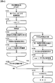
- a flowchart showing the operation of the internal parameter estimation unit 206 Subroutine showing details of processing in step S604 of FIG.
- Functional block diagram of an internal parameter calibration program in the second embodiment The flowchart showing the operation of the focal length estimation unit in the second embodiment
- FIG. 1 is a block diagram illustrating a configuration of a camera calibration device 100 according to the present invention and a vehicle 1 including the camera calibration device 100.
- the vehicle 1 measures the speed of the camera 1, the camera 111 that captures the front of the vehicle 1, the display device 104 that presents information to the driver based on the output of the camera calibration device 100, and the speed of the vehicle 1.
- the slope of the road surface on which the vehicle 1 is grounded is constant, and at least the slope of the road surface in the range photographed by the camera 111 coincides with the slope of the road surface installed by the vehicle. That is, for example, the following description will be continued assuming that the vehicle is traveling on a wide horizontal plane or is traveling on the middle of a slope with a constant gradient.
- the camera 111 is attached to the front of the vehicle 1, and the optical axis is the front of the vehicle 1 and is fixed below the horizontal direction.
- the positional / posture relationship between the camera 111 and the vehicle 1 is stored in a flash memory 112 described later as an external parameter. Since it is inevitable that the camera 111 is attached to the vehicle 1, the correction is appropriately made by a known calibration method.
- the camera 111 includes a lens and an image sensor, and these characteristics, for example, a lens distortion coefficient that is a parameter indicating lens distortion, an optical axis center, a focal length, the number of pixels of the image sensor, and a size are stored in the ROM 103 as initial values of internal parameters. Is done. Further, internal parameters including a lens distortion coefficient calculated by a calibration program described later are stored in the flash memory 112.
- the camera calibration apparatus 100 includes a CPU 101 that performs calculation, a RAM 102, a ROM 103, and a flash memory 112.
- the CPU 101 is connected to the RAM 102, RAM 103, and flash memory 112 through signal lines.
- the CPU 101 develops a program stored in the ROM 103 on the RAM 102 and executes it.
- the RAM 102 stores tracking point information 102A used by a program to be described later and a work table 102B. The structure of the tracking point information 102A will be described later.
- the work table 102B is obtained by duplicating and processing a part of the tracking point information 102A, and is created by processing described later.
- the ROM 103 stores an internal parameter calibration program 103A, an internal parameter initial value 103B, a camera use program 103C, and an external parameter initial value (not shown).
- the operation of the internal parameter calibration program 103A will be described later using a flowchart.
- the camera use program 103C is a program that uses the camera 111. For example, when a distance from a surrounding vehicle is calculated using an image obtained by the camera 111, and the distance is equal to or less than a predetermined distance, A warning is displayed on the display device 104.
- the camera utilization program 103 ⁇ / b> C requires external parameters and internal parameters of the camera 111 for execution, and reads them from the flash memory 112. However, when the external parameter and the internal parameter are not stored in the flash memory 112, the internal parameter initial value 103B and the external parameter initial value stored in the ROM 103 are used.
- the flash memory 112 is a nonvolatile storage medium, and the flash memory 112 stores an internal parameter 112A including a lens distortion coefficient output by the internal parameter calibration program 103A and an external parameter (not shown).
- the input unit 109 is composed of switches, buttons, and the like, and accepts user operations. This is used for turning on / off the calibration function, initializing the calibration result, changing the calibration method, and the like.
- FIG. 2 is a diagram illustrating functions of the internal parameter calibration program 103 ⁇ / b> A executed by the CPU 101 as function blocks, and illustrates a data flow between the function blocks and between the function blocks and the RAM 102.
- the internal parameter calibration program 103A includes an image acquisition unit 201, a feature point extraction unit 202, a feature point tracking unit 203, a vehicle motion acquisition unit 204, a feature point locus storage unit 205, and an internal parameter estimation unit as functional blocks. 206.
- the image acquisition unit 201, the feature point extraction unit 202, and the feature point tracking unit 203 are executed every time the camera 111 captures an image.
- the camera 111 shoots continuously at a high frequency, for example, 60 times per second while the vehicle 1 is traveling. An image obtained by photographing with the camera 111 (hereinafter referred to as a photographed image) is transmitted to the camera calibration apparatus 100.
- the image acquisition unit 201 receives a captured image from the camera 111 and outputs the received captured image to the feature point extraction unit 202 and the feature point tracking unit 203.
- the camera 111 shoots continuously at a high frequency, for example, 60 times per second while the vehicle 1 is traveling, and the image acquisition unit 201 inputs a photographic image from the camera 111 every time it receives a photographic image from the camera 111. Each time it is taken, the captured image is output to the feature point extraction unit 202 and the feature point tracking unit 203.
- the feature point extraction unit 202 performs image processing on the captured image input from the image acquisition unit 201 and extracts feature points.
- the feature point here is, for example, an intersection of edges such as a corner of a wall, a corner of a curb, or a corner of a broken line in the image, that is, a corner feature point.
- the corner feature point can be extracted by applying a Harris operator which is a known technique, for example.
- the feature points extracted by the feature point extraction unit 202 can be specified by, for example, coordinates in the captured image of the camera 111. In the present embodiment, as shown in FIG.
- the upper left of the captured image is defined as the origin, the right is defined as the positive direction of the X axis, and the lower is defined as the positive direction of the Y axis.
- the feature points extracted by the feature point extraction unit 202 are stored in the RAM 102.
- the feature point tracking unit 203 is information read from the RAM 102 and is input from the latest captured image input from the image acquisition unit 201 and the vehicle motion acquisition unit 204 for the feature point obtained from the immediately preceding captured image. Tracking processing is performed using motion information. For tracking feature points, SAD (Sum of Absolute Difference), SSD (Sum of Squared Difference), LK (Lucas-Kanade), etc., which are known tracking methods, can be used. Then, information regarding the tracked feature points is output to the feature point locus accumulating unit 205.
- the vehicle motion acquisition unit 204 calculates the motion information of the vehicle 1 based on the outputs of the vehicle speed sensor 105 and the gyro sensor 108, for example, the travel trajectory and speed of the vehicle 1 to the feature point tracking unit 203 and the feature point trajectory storage unit 205. Output.
- the feature point locus storage unit 205 stores the feature point locus obtained by the feature point tracking unit 203 in the tracking point information 102 ⁇ / b> A of the RAM 102.
- an erroneous feature point trajectory is eliminated, only a highly reliable feature point trajectory is left, or one with higher calibration accuracy is selected.
- the internal parameter estimation unit 206 estimates the lens distortion coefficient using the tracking point information 102 A stored in the RAM 102 by the feature point locus storage unit 205 and writes the lens distortion coefficient in the flash memory 112. At this time, internal parameters other than the lens distortion coefficient are read from the ROM 103 and drawn in accordance with the flash memory 112.
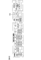
- FIG. 3 is a diagram illustrating an example of the tracking point information 102 ⁇ / b> A stored in the RAM 102.
- the rows in FIG. 3 represent individual feature points, and the columns represent the coordinates of the feature points on the photographed image at the photographing times t1 to t5, the state of the feature point locus, the area to which the feature point locus belongs, and the approximate expression of the feature point locus. .
- Numbers assigned to feature points that is, 1001, 1002, etc., are numbers assigned in the order of extraction.
- FIG. 3 shows that two feature points are extracted from the photographed image taken at time t1, and similarly, four of the photographed images taken at times t2 and t3 are photographed at time t4.
- the “state” column of the tracking point information 102A is referred to when determining whether or not the feature points are used for calibration of internal parameters. In this column, if the feature point tracking is continued, “not yet”, if the movement of the vehicle 1 and the feature point locus do not match, “mismatch”, other similar feature point locus exists. If not, “No Pair” is entered, otherwise “OK” is entered.
- the “area” column of the tracking point information 102A indicates the area to which the trajectory of the feature point belongs.
- the column of “multinomial approximation” in the tracking point information 102A indicates an expression obtained by approximating the trajectory of the feature point with a polynomial.
- FIG. 4 is a flowchart showing the operation of the feature point extraction unit 202.
- the feature point extraction unit 202 performs the following operation each time a captured image is transmitted from the image acquisition unit 201.
- step S ⁇ b> 301 the feature point extraction unit 202 determines a region in the photographed image from which the feature points are extracted based on the traveling direction of the vehicle 1 and the photographing direction of the camera 111 with respect to the traveling direction of the vehicle 1.
- the processing region is set so as to extract feature points at locations away from the vehicle.
- the processing region is set on the side closer to the vehicle when the vehicle travels forward. Next, the process proceeds to step S302.
- step S302 feature points are extracted for the feature point extraction region set in step S301.
- a corner feature point is extracted by applying a Harris operator or the like to the region set in step S301, and the process proceeds to step S303.
- step S303 the coordinates of the feature points extracted in step S302 are output to the RAM 102, and the flowchart of FIG.
- FIG. 5 is a flowchart showing the operation of the feature point tracking unit 203.
- the feature point tracking unit 203 performs the following operation every time a captured image is transmitted from the image acquisition unit 201.
- step S401 a processing area to be subjected to feature point tracking processing is set. That is, in the captured image captured immediately before by the camera 111, the immediately preceding captured image is obtained using the coordinates from which the feature points are extracted by the feature point extracting unit 202 and the motion information of the vehicle 1 acquired by the vehicle motion acquiring unit 204. The direction and distance in which the extracted feature points move are estimated.
- the captured image used for estimating the moving direction and distance of the feature point is not limited to the immediately preceding captured image, and may be estimated using a plurality of captured images, or may be used for captured images other than the immediately preceding captured image. It may be estimated. That is, the direction and distance in which the feature point moves is estimated using a captured image captured at an earlier time.
- Steps S402 to S405 to be described next are repeatedly executed a number of times corresponding to the feature points extracted in the immediately preceding captured image.
- the feature point in the immediately preceding captured image read from the RAM 102 that is the tracking target is tracked by a known method such as the SAD or LK method described above, and the process proceeds to step S403.
- step S403 it is determined whether or not the feature point tracking in the immediately preceding captured image that is the tracking target has been continued. For example, if the collation degree by SAD or the like is equal to or less than a predetermined threshold value, it is determined that the tracking cannot be performed because the camera is out of the angle of view of the camera. If it is determined that the tracking has been continued, the process proceeds to step S404. If it is determined that the tracking has not been continued, the process proceeds to step S405.
- step S404 the coordinates of the tracked feature point are recorded in the row of the feature point to be processed in the tracking point information 102A and in the column of the time when the captured image to be processed is captured.
- step S405 a mark for which tracking is completed, for example, “x”, is recorded in the row of the feature point to be processed in the tracking point information 102A and in the column of the time when the captured image to be processed is captured.
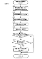
- FIG. 6 is a flowchart showing the operation of the feature point locus accumulating unit 205.
- step S501 the tracking point information 102A is read from the RAM 102, and “mismatch” is recorded in the “state” column of the feature point trajectory that does not match the motion information output by the vehicle motion acquisition unit 204. For example, if a feature point trajectory stays or draws a trajectory opposite to the traveling direction even though the vehicle is traveling at 60 km / h, the trajectory is not a trajectory of a feature point on the road surface. It can be judged.
- mistracking is unavoidable due to changes in sunshine conditions, changes in weather, shadows of the host vehicle and other vehicles. If the erroneous tracking result is used for calibration, correct calibration cannot be performed. Therefore, such a tracking result is excluded by the processing in step S501.
- step S502 the process proceeds to step S502.
- each of the feature points extracted by the feature point extraction unit 202 that is, the area to which the trajectory of the feature point belongs is specified.
- the captured image obtained by capturing by the camera 111 is divided into a plurality of areas as will be described later, and in this step, it is specified to which area the feature point locus belongs. If the trajectory of feature points used for internal parameter estimation is localized only in part of the captured image, the internal parameter estimation accuracy will be low, so calibration should be performed after the features are obtained over the entire image. It is desirable. For this reason, this process determines which area in the captured image the feature point locus belongs to.
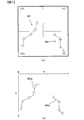
- FIG. 7A shows an example of an area in a captured image to which a feature point locus belongs.
- a first feature point locus 801 indicated by a circular marker and a second feature point locus 802 indicated by a triangular marker are stored in the tracking point information 102A.
- the captured images of the camera 111 are classified into four areas (A) to (D) as shown in FIG.
- the feature point trajectory 801 belongs to area (a) and area (c)
- the feature point trajectory 802 belongs to area (d). That is, in the example shown in FIG. 7A, there is no feature point locus belonging to area (A).
- the feature point trajectory is a line segment connecting the tracked feature points with a straight line.
- step S503 a plurality of straight lines connecting the tracked feature points are approximated using one polynomial.
- approximation is performed with a quintic equation represented by the following equation (1) to obtain parameters a to e.
- Y ax ⁇ 5 + bx ⁇ 4 + cx ⁇ 3 + dx ⁇ 2 + ex + f
- FIG. 7B is a diagram illustrating an example in which a line segment connecting tracked feature points is approximated by a single curve. The trajectory of the feature points illustrated in FIG. 7B is the same as the trajectory of the feature points illustrated in FIG. In FIG.
- a feature point locus 801 represented by a plurality of line segments is approximated by a single curve 801a, and similarly, a feature point locus 802 is approximated by a curve 802a.
- the process proceeds to step S504.
- step S504 the area to which each feature point trajectory calculated in step S502 belongs and a polynomial that approximates the feature point trajectory calculated in step S503 are stored in the tracking point information 102A, and the process proceeds to step S505.
- step S505 it is determined whether or not there are approximate expressions that are substantially coincident with each other among the approximate expressions recorded in the tracking point information 102A. If there are other polynomials that substantially coincide with each other, the “state” of the tracking point information 102A is determined. "OK" is entered in the "" column, and if there is no other polynomial that substantially matches, "No Pair” is entered in the same manner, and the process proceeds to step S506.
- Whether or not the polynomials substantially match can be determined by whether or not the difference between the coefficients of the polynomials is within a predetermined value. For example, assume that two feature point trajectories are approximated by the following equations (2) and (3), respectively.
- Y a 1 x ⁇ 5 + b 1 x ⁇ 4 + c 1 x ⁇ 3 + d 1 x ⁇ 2 + e 1 x + f 1 .. (2)
- Y a 2 x ⁇ 5 + b 2 x ⁇ 4 + c 2 x ⁇ 3 + d 2 x ⁇ 2 + e 2 x + f 2 ...
- step S506 the tracking point information 102A is referred to and it is determined whether or not there are a predetermined number or more of feature point trajectories that substantially match. In other words, it is determined whether or not the number of “OK” in the “state” column of the tracking point information 102A is a predetermined number or more. If it is determined that the condition is satisfied, the process proceeds to step S507. If it is determined that the condition is not satisfied, the process illustrated in FIG.
- step S507 the tracking point information 102A is referred to, focusing on the “area” column of the feature point trajectory in which the “state” column of the tracking point information 102A is “OK”, and at least one or more of all the areas is covered. It is determined whether or not a feature point locus exists. That is, in this step, it is determined whether or not the feature point trajectory used for estimating the internal parameter is distributed over a wide range in the captured image of the camera 111. If it is determined that the condition is satisfied, the process proceeds to step S508. If it is determined that the condition is not satisfied, the process illustrated in FIG. In step S508, an execution command is output to the internal parameter estimation unit 206, and the process shown in FIG.
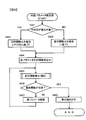
- FIG. 8 is a flowchart showing the operation of the internal parameter estimation unit 206.
- the internal parameter estimation unit 206 starts its operation when it receives an execution command from the feature point locus storage unit 205.
- a lens distortion coefficient that minimizes an objective function described later is obtained by repeated calculation.
- the lens distortion coefficient temporarily set in the process of repeated calculation is referred to as “temporary parameter”.
- step S601 whether there is a combination of feature points that can be evaluated for parallelism in the feature point trajectory recorded in the tracking point information 102A and in which the “state” column is “OK”. In other words, it is determined whether or not there are one or more sets of feature points having substantially the same Y coordinate in a plurality of consecutive captured images. If it is determined that there is a feature point that satisfies the condition, the process proceeds to step S602. If it is determined that no feature point satisfies the condition, the process proceeds to step S603. In step S602, an objective function to be described later is calculated based on collinearity and parallelism, and the process proceeds to step S604.
- step S603 which is executed when a negative determination is made in step S601, an objective function described later is calculated based only on collinearity, and the process proceeds to step S604.
- step S604 the lens distortion coefficient of the internal parameter 112A stored in the flash memory 112 is read as a temporary parameter.
- the internal parameter initial value 103 B is read from the ROM 103.
- step S605 the objective function is calculated from the temporary parameters, the motion information output by the vehicle motion acquisition unit 204, the trajectory of the feature points stored in the tracking point information 102A, and the viewpoint determined in step S602 or step S603. That is, an objective function based on collinearity and parallelism, or an objective function based only on collinearity is calculated. Details will be described with reference to FIG. By this step, a scalar value that is an evaluation value of the objective function is obtained. Next, the process proceeds to step S606.
- step S606 it is determined whether the objective function has converged, that is, whether the difference between the previous objective function and the current objective function is equal to or less than a predetermined value. If it is determined that the objective function has converged, the process proceeds to step S608. If it is determined that the objective function has not converged, the process proceeds to step S607. However, since it is impossible to determine whether or not it has converged at the first execution, this step makes a negative determination.
- step S607 the temporary parameter is updated, and the process returns to step S605. For example, by using a well-known technique such as the Levenberg-Marquardt method, the temporary parameter can be updated so that the objective function decreases.
- step S608 the parameters when the objective function has converged are output, and the processing shown in FIG. 8 ends.
- FIG. 9 is a subroutine showing details of the processing in step S605 of FIG.
- step S701 the trajectory of the feature point described in the tracking point information 102A and having the “state” column “OK” is copied to the RAM 102 as the work table 102B. Further, the coordinates of the feature points described in the work table 102B are converted using the temporary parameters.
- calculation is performed using the feature points after coordinate conversion described in the work table 102B.
- step S702 initialization is performed by substituting zero into a variable eval which is an evaluation value of the objective function, and the process proceeds to step S703.
- Steps S703 to S705 described below are executed for each feature point described in the work table 102B.
- the locus of the ideal feature point corresponding to the travel of the vehicle 1 based on the motion information is calculated using the coordinates of the feature point to be processed at the oldest time as the starting point.
- the ideal feature point trajectory is the trajectory of the feature point when the lens of the camera 111 is not distorted, that is, the trajectory of the feature point when the influence of the lens distortion of the camera 111 can be completely removed by the internal parameters. .
- the trajectory of the ideal feature point can be estimated as a straight line.
- step S704 the collinearity evaluation value is calculated using the ideal trajectory calculated in step S703 and the trajectory described in the work table 102B.
- the purpose of this embodiment is to minimize the objective function, so that the evaluation of the collinearity becomes smaller as the distance between the ideal trajectory and the trajectory described in the work table 102B becomes shorter.
- the collinearity evaluation value is the sum of the distances from the respective feature point coordinates described in the work table 102B with respect to the ideal trajectory.
- the process proceeds to step S705.
- step S705 the collinearity evaluation value calculated in step S704 is added to the variable eval. If execution of steps S703 to S705 has been completed for all feature points described in the work table 102B, the process proceeds to step S706, and if there is a feature point that has not yet been completed, the process returns to step S703. In step S706, it is determined whether or not parallelism is also evaluated, that is, whether or not an affirmative determination is made in step S601. If it is determined that a positive determination is made, the process proceeds to step S707. If it is determined that a negative determination is made, the process proceeds to step S710.
- Steps S707 to S709 described below are executed for each combination of feature points determined to be parallel in the work table 102B.
- step S707 a line segment connecting the feature point coordinates at the same time is generated for the feature points determined to be parallel, and the process proceeds to step S708.
- step S708 the parallelism of the plurality of line segments generated in step S707 is evaluated in consideration of the motion information of the vehicle 1.
- the parallelism is evaluated so that the line segments are not parallel to each other so that the value becomes larger. For example, a value obtained by removing the rotation angle of the vehicle from the angle formed by the line segments is used as the evaluation value.
- step S709 a value obtained by removing the rotation angle of the vehicle from the angle formed by the line segments is used as the evaluation value.
- step S709 the parallelism evaluation value calculated in step S708 is added to the variable eval. If the execution of steps S707 to S709 has been completed for all parallel feature point combinations described in the work table 102B, the process proceeds to step S710, and if there is a feature point that has not been completed yet, the process returns to step S707.
- step S710 the variable eval is output as the value of the objective function, the work table 102B is deleted from the RAM 102, and the flowchart of FIG.
- the camera calibration apparatus 100 includes an image acquisition unit 201 to which a plurality of images obtained by photographing the camera 111 mounted on the vehicle 1 at different times and an image acquisition unit 201 that inputs the images.
- a feature point extraction unit 202 that extracts feature points from the images
- a feature point tracking unit 203 that tracks feature points between a plurality of images
- a vehicle motion acquisition unit 204 that acquires information related to vehicle motion, and vehicle motion acquisition.
- a trajectory estimation unit step S703 in FIG.
- an internal parameter estimation unit that estimates an internal parameter of the camera 111, that is, a lens distortion coefficient that is a parameter indicating lens distortion, based on the trajectory of the feature point estimated by the estimation unit. And a 06. Since the camera calibration device 100 is configured in this way, feature points are extracted from road markings drawn on the road surface and the lens distortion coefficient is calibrated. In other words, since the line, symbol, or character drawn on the road surface is used, the lens distortion coefficient can be calibrated even if there is no white line on the road surface.
- the internal parameter includes a lens distortion coefficient corresponding to the distortion of the lens provided in the camera 111.
- the internal parameter estimation unit 206 includes a feature point trajectory (step S701 in FIG. 9) obtained by converting the feature point trajectory tracked by the feature point tracking unit 203 using a lens distortion coefficient, and a trajectory estimation unit (step in FIG. 9).
- the lens distortion coefficient is calculated so as to minimize the difference from the trajectory of the feature point estimated in S703. That is, the lens distortion coefficient of the camera 111 can be estimated by estimating the position of the feature point extracted from the road sign drawn on the road surface in the photographed image of the camera 111 using the motion information of the vehicle 1.
- the camera calibration apparatus 100 includes a trajectory approximation unit (step S503 in FIG. 6) that approximates the trajectory of the feature point tracked by the feature point tracking unit 203 using a polynomial, and the trajectory approximation unit is the first feature point. And the trajectory of the first feature point and the trajectory of the second feature point based on the difference between the coefficient of the polynomial approximating the trajectory and the coefficient of the polynomial whose trajectory approximating unit approximates the trajectory of the second feature point. And a coincidence determination unit (step S505 in FIG. 6) for determining whether or not the two match.
- the internal parameter estimation unit 206 estimates the lens distortion coefficient of the camera 111 using the trajectory of the first feature point and the trajectory of the second feature point that the match determination unit determines to match. The more similar the feature point trajectory is obtained, the higher the reliability of the trajectory of the feature point is considered as the trajectory of the road marking on the road surface, not the noise trajectory. Therefore, the lens distortion coefficient of the camera 111 can be calculated with high accuracy by using feature point trajectories having approximately the same approximate expression.
- the internal parameter estimation unit 206 estimates the internal parameters of the camera 111 when the feature point trajectory tracked by the feature point tracking unit 203 is included in all of the plurality of regions obtained by dividing the image (see FIG. 6). Step S507).
- the feature point locus is localized only in a part of the photographed image, information on distortion of the entire lens surface is not obtained, and sufficient calibration accuracy cannot be obtained. For this reason, the fact that the feature points are distributed over a wide range of the captured image is set as an execution condition of the internal parameter estimation, thereby preventing a reduction in calibration accuracy.
- the internal parameter estimation unit 206 determines that the vehicle 1 is traveling straight based on the motion information, the internal parameter estimation unit 206 estimates the trajectory of the feature point as a straight line. For this reason, if the vehicle 1 is limited to a situation where the vehicle 1 goes straight, the internal parameters can be calibrated without using external parameters.
- the internal parameter estimation unit 206 uses the external parameters of the camera 111 and the motion information acquired by the vehicle motion acquisition unit 204 to calculate the feature points. Estimate the trajectory. Therefore, even when the vehicle 1 is turning, the internal parameters can be calibrated using the external parameters and the motion information.
- the feature point extraction unit 202 determines a region in the image from which feature points are extracted based on the traveling direction of the vehicle 1 and the shooting direction of the camera 111 with respect to the traveling direction of the vehicle 1. Therefore, feature points are extracted on the premise of tracking. Therefore, by excluding a region that cannot be tracked immediately after extraction from the processing region, the load on the feature point extraction unit 202 can be reduced.
- the feature point extraction unit 202 is executed every time the camera 111 performs shooting, and the process needs to be completed before the camera 111 performs shooting next time. For this reason, when the load on the feature point extraction unit 202 increases, it is necessary to increase the processing capability of the CPU 101 of the camera calibration device 100. In other words, by reducing the load on the feature point extraction unit 202, an inexpensive product with low processing capability can be used for the CPU 101 of the camera calibration apparatus 100.
- the feature point tracking unit 203 acquires the position where the feature point is extracted by the feature point extraction unit 202 in the first image taken at the previous time among the plurality of images, and the vehicle motion acquisition unit 204 acquires it. Using this information, an area for tracking the feature point in the second image taken at a later time than the first image is determined among the plurality of images. Therefore, the processing area of the feature point tracking unit 203 can be limited, and the load on the feature point tracking unit 203 can be reduced.
- the feature point tracking unit 203 is executed every time the camera 111 captures an image, and the process needs to be completed before the camera 111 captures the next image.
- Modification 1 In the first embodiment described above, the feature point tracked by the feature point tracking unit 203, that is, the feature point cannot be tracked in the next captured image, and “x” is recorded in the tracking point information 102A. Only feature points were used for internal parameter calibration. However, feature points that have not been tracked may also be used for internal parameter calibration.
- the vehicle 1 includes only one camera 111.
- the vehicle 1 may include a plurality of cameras.
- the same number of camera calibration devices 100 as the cameras may be prepared, or only one camera calibration device 100 is provided and the internal parameters of the plurality of cameras are calibrated in order. May be.
- the internal parameter calibration program 103A described in the first embodiment can be applied regardless of the mounting position of the camera provided in the vehicle and the shooting direction of the camera.
- the camera calibration apparatus 100 further includes a distortion correction unit that corrects the captured image as described below, and the feature point extraction unit 202 and the feature point tracking unit 203 perform processing using the captured image corrected by the distortion correction unit. May be performed.
- the CMOS sensor includes a plurality of photodiodes arranged in a matrix, and these photodiodes are sequentially exposed and read out row by row.
- the difference between the exposure and readout times for each row is known, and the motion information of the vehicle 1 on which the camera 111 is mounted is obtained from the vehicle motion acquisition unit 204. Therefore, the distortion correction unit removes distortion from the captured image of the camera 111 based on the difference in exposure / readout time for each row of the CMOS sensor, the motion information of the vehicle 1, and the external parameters of the camera 111, and the feature point extraction unit 202. And output to the feature point tracking unit 203.
- the distortion correction unit removes distortion from the captured image of the camera 111 based on the difference in exposure / readout time for each row of the CMOS sensor, the motion information of the vehicle 1, and the external parameters of the camera 111, and the feature point extraction unit 202. And output to the feature point tracking unit 203.
- the slope of the road surface on which the vehicle 1 is grounded is constant, but the slope of the road surface in the range photographed by the camera 111 does not match the slope of the road surface on which the vehicle is grounded.
- the present invention can also be applied to cases. In that case, a change in the road surface gradient is imaged in the process (step S703 in FIG. 9) of estimating the road surface gradient of the shooting range with respect to the posture of the vehicle 1 by means described later and calculating the trajectory of the ideal feature point. This can be dealt with by considering the effect of the feature point trajectory on the image.
- the means for estimating the road surface gradient of the shooting range with respect to the attitude of the vehicle 1 can use, for example, a combination of map information including the position and orientation of the vehicle 1 and road gradient information by a satellite positioning system, or along the road surface.
- map information including the position and orientation of the vehicle 1 and road gradient information by a satellite positioning system, or along the road surface.
- Existing linear objects such as white lines and guardrails, horizontal edges of buildings along the road, and inclinations of other vehicles traveling on the road can also be used.
- the internal parameter calibration is always executed, but may be executed only when the temperature and time conditions are satisfied.
- the vehicle 1 further includes a thermometer, records the temperature when the internal parameter is calibrated, and performs internal parameter calibration again when the temperature changes from that temperature by a predetermined temperature or more, for example, 5 degrees or more. May be.
- the temperature measured by the thermometer may be the temperature of the camera 111 or the temperature of the outside air, or the temperature of the passenger compartment of the vehicle 1 may be measured.
- internal parameters may be calibrated at regular intervals.
- the captured image is divided into four areas in step S502 of FIG. 6, and it is determined which area the feature point locus belongs to.
- the number of area divisions and the division method are not limited thereto.
- the number of divided areas may be at least two.
- the division of the area is not limited to a matrix, and the area may be divided only in the X direction or may be divided only in the Y direction.
- the area is not limited to a rectangle and may be a circle, an indeterminate shape, or may be randomly divided.
- one of the conditions for operating the internal parameter estimation unit 206 is that at least one feature point locus exists in all areas in the captured image (step in FIG. 6). S507).
- the number of trajectories of feature points under the condition is not limited to 1, and may be 2 or 3 or more.
- FIGS. 1-10 A second embodiment of the camera calibration device according to the present invention will be described with reference to FIGS.
- the same components as those in the first embodiment are denoted by the same reference numerals, and different points will be mainly described. Points that are not particularly described are the same as those in the first embodiment.
- the present embodiment is different from the first embodiment mainly in that in addition to lens distortion, the focal length of the lens is also subject to calibration.
- FIG. 10 is a diagram illustrating functions of the internal parameter calibration program 103A according to the second embodiment as function blocks.
- the internal parameter estimation unit 206A of the internal parameter calibration program 103A also calibrates the focal length in addition to the lens distortion coefficient.
- FIG. 11 is a flowchart showing the focal length calibration operation by the internal parameter estimation unit 206A.
- step S801 the image sensor size and external parameters, which are one of the internal parameters of the camera 111, are read from the ROM 103, and the process proceeds to step S802.
- step S802 the tracking point information 102A is read, and the process proceeds to step S803.
- Steps S803 to S807 described below are executed for each feature point whose “state” column in the work table 102B is “OK”.
- step S803 the shooting time when the tracking of the feature point is started (hereinafter, time ts) and the shooting time when the tracking is ended (hereinafter, time te) are specified. For example, in the example illustrated in FIG. 3, when the feature point 1001 is a processing target, the shooting time when tracking is started is “t1”, and the shooting time when tracking is ended is “t3”. Next, the process proceeds to step S804.
- step S804 the distance between the feature point to be processed at the time ts specified in step S803 and the camera 111 is calculated as a function of the focal length f. Since the image sensor size of the camera 111 is known, the angle of view of the camera 111 can be expressed using the focal length f, and further, processing can be performed by using known external parameters, that is, the mounting position and mounting posture of the camera 111 with respect to the vehicle. The distance between the target feature point and the camera 111 can be calculated as a function of the focal length f. Hereinafter, this distance is referred to as dts . Next, the process proceeds to step S805.
- step S805 the distance between the feature point to be processed at the time te specified in step S803 and the camera 111 is calculated as a function of the focal length f.
- the calculation method is the same as that in step S804. Below, this distance is called dte .
- step S806 the movement distance output by the vehicle movement acquisition unit 204 is used to calculate the linear distance that the vehicle 1 has moved from time ts to time te. Hereinafter, this linear distance is referred to as d ts-te .
- the camera calibration apparatus 100 includes an image acquisition unit 201 to which a plurality of images obtained by photographing the camera 111 mounted on the vehicle 1 at different times and an image acquisition unit 201 that inputs the images.
- a feature point extraction unit 202 that extracts feature points from the images
- a feature point tracking unit 203 that tracks feature points between a plurality of images
- a vehicle motion acquisition unit 204 that acquires information related to vehicle motion, and vehicle motion acquisition.
- a trajectory estimation unit step S703 in FIG.
- an internal parameter estimation unit 206 that estimates the internal parameters of the camera 111, that is, the lens distortion coefficient and the focal length, based on the trajectory of the feature points estimated by the estimation unit. Since the camera calibration device 100 is configured in this way, feature points are extracted from road markings drawn on the road surface, and the lens distortion coefficient and focal length are calibrated. In other words, since the line, symbol, or character drawn on the road surface is used, the lens distortion coefficient and the focal length can be calibrated even if there is no white line on the road surface.
- the internal parameter includes a focal length of a lens provided in the camera.
- the camera calibration device 100 calculates a first distance d ts that is the distance between the position of the feature point at the first time ts and the camera 111 according to the focal length f (step S804 in FIG. 11). ), And a second distance calculation unit that calculates a second distance d te , which is a distance between the position of the feature point tracked by the feature point tracking unit 203 at the second time te and the camera 111, according to the focal length f (see FIG.
- step S805 and the movement distance for calculating the movement distance d ts-te that is the distance the vehicle has moved from the first time ts to the second time te based on the information acquired by the vehicle motion acquisition unit 204.
- step S806 in FIG. 11 a calculation unit (step S806 in FIG. 11).
- the focal length f of the lens provided in the camera 111 is calculated. Therefore, the focal length f can be calculated using road markings on the road surface that are not limited to white lines.
- the distance between the camera 111 and the position of the feature point at the time t5 when the tracking of the feature point is started and the time te when the tracking is finished is calculated.
- the focal distance f may be calculated by calculating the distance between the feature point position and the camera 111.
- 1 ... vehicle, 100 ... camera calibration device, 102A ... tracking point information, 103A ... internal parameter calibration program, 111 ... camera, 112 ... flash memory, 112A ... internal parameters, 201 ... image acquisition unit, 202 ... feature point extraction , 203 ... feature point tracking section, 204 ... vehicle motion acquisition section, 205 ... feature point locus storage section, 206, 206A ... internal parameter estimation section
Abstract
This camera calibration device is provided with: an image acquisition unit into which a plurality of images captured at different times by a camera mounted to a vehicle are inputted; a feature point extraction unit which extracts features points from each of the images inputted into the image acquisition unit; a feature point tracking unit which tracks the feature points between the plurality of images; a vehicle movement acquisition unit which acquires information related to the movement of the vehicle; a trajectory estimation unit which, on the basis of the information acquired by the vehicle movement acquisition unit, estimates the trajectory of the feature points corresponding to the movement of the vehicle; and an internal parameter estimation unit which estimates internal parameters of the camera on the basis of the trajectory of the feature points tracked by the feature point tracking unit, and the trajectory of the feature points estimated by the trajectory estimation unit.
Description
本発明は、カメラキャリブレーション装置に関する。
The present invention relates to a camera calibration device.
近年、安全装備としてカメラの自動車への搭載が進んでいる。カメラは周囲の俯瞰映像の運転者への提示、車線逸脱の防止、歩行者や車両の認識に基づく警報出力、衝突回避など、種々のアプリケーションで用いられ、自動車の安全性と利便性の向上に寄与している。これらのアプリケーションにおいてカメラと被写体との位置関係を算出するためには、カメラの外部パラメータと内部パラメータが必要となる。
外部パラメータとは、車両とカメラの関係を表すパラメータであり、たとえば車両に対するカメラの取り付け位置および姿勢を示すパラメータである。内部パラメータとは、カメラ内部の光学系に関するパラメータであり、たとえば焦点距離やレンズの歪みを示すパラメータである。レンズの生産時にあらかじめ歪みに関するパラメータが測定され、その測定結果を内部パラメータとして用いることもできるが、車載カメラは車内温度の変化や基板の発熱でカメラ筐体が伸縮しレンズの歪み特性が変化する。すなわち、あらかじめ求めた内部パラメータをそのまま用いると不都合が生じる。たとえば、カメラで撮影した画像と内部パラメータを用いて被写体までの距離を算出した場合に、その距離に無視できない誤差が生じる。そのため、車両の走行中の内部パラメータのキャリブレーションが求められる。
特許文献1には、路面の白線を用いて内部パラメータを推定するカメラキャリブレーション装置が開示されている。 In recent years, cameras have been installed in automobiles as safety equipment. Cameras are used in a variety of applications, such as presenting surrounding bird's-eye views to the driver, preventing lane departure, warning output based on pedestrian and vehicle recognition, and collision avoidance to improve the safety and convenience of automobiles. Has contributed. In these applications, in order to calculate the positional relationship between the camera and the subject, external parameters and internal parameters of the camera are required.
The external parameter is a parameter that represents the relationship between the vehicle and the camera, for example, a parameter that indicates the attachment position and orientation of the camera with respect to the vehicle. The internal parameter is a parameter related to the optical system inside the camera, and is a parameter indicating, for example, a focal length or lens distortion. Parameters related to distortion are measured in advance during lens production, and the measurement results can be used as internal parameters. However, in-vehicle cameras are subject to changes in lens distortion characteristics due to the expansion and contraction of the camera housing due to changes in the interior temperature and heat generation of the board. . That is, inconvenience arises if the internal parameters obtained in advance are used as they are. For example, when a distance to a subject is calculated using an image captured by a camera and internal parameters, an error that cannot be ignored occurs in the distance. Therefore, calibration of internal parameters during vehicle travel is required.
Patent Document 1 discloses a camera calibration device that estimates an internal parameter using a white line on a road surface.
外部パラメータとは、車両とカメラの関係を表すパラメータであり、たとえば車両に対するカメラの取り付け位置および姿勢を示すパラメータである。内部パラメータとは、カメラ内部の光学系に関するパラメータであり、たとえば焦点距離やレンズの歪みを示すパラメータである。レンズの生産時にあらかじめ歪みに関するパラメータが測定され、その測定結果を内部パラメータとして用いることもできるが、車載カメラは車内温度の変化や基板の発熱でカメラ筐体が伸縮しレンズの歪み特性が変化する。すなわち、あらかじめ求めた内部パラメータをそのまま用いると不都合が生じる。たとえば、カメラで撮影した画像と内部パラメータを用いて被写体までの距離を算出した場合に、その距離に無視できない誤差が生じる。そのため、車両の走行中の内部パラメータのキャリブレーションが求められる。
特許文献1には、路面の白線を用いて内部パラメータを推定するカメラキャリブレーション装置が開示されている。 In recent years, cameras have been installed in automobiles as safety equipment. Cameras are used in a variety of applications, such as presenting surrounding bird's-eye views to the driver, preventing lane departure, warning output based on pedestrian and vehicle recognition, and collision avoidance to improve the safety and convenience of automobiles. Has contributed. In these applications, in order to calculate the positional relationship between the camera and the subject, external parameters and internal parameters of the camera are required.
The external parameter is a parameter that represents the relationship between the vehicle and the camera, for example, a parameter that indicates the attachment position and orientation of the camera with respect to the vehicle. The internal parameter is a parameter related to the optical system inside the camera, and is a parameter indicating, for example, a focal length or lens distortion. Parameters related to distortion are measured in advance during lens production, and the measurement results can be used as internal parameters. However, in-vehicle cameras are subject to changes in lens distortion characteristics due to the expansion and contraction of the camera housing due to changes in the interior temperature and heat generation of the board. . That is, inconvenience arises if the internal parameters obtained in advance are used as they are. For example, when a distance to a subject is calculated using an image captured by a camera and internal parameters, an error that cannot be ignored occurs in the distance. Therefore, calibration of internal parameters during vehicle travel is required.
特許文献1に記載されている発明では、路面に白線がなければ内部パラメータのキャリブレーションができない。
In the invention described in Patent Document 1, internal parameters cannot be calibrated unless there is a white line on the road surface.
本発明の第1の態様によると、カメラキャリブレーション装置は、車両に搭載されるカメラが異なる時刻に撮影して得られた複数の画像が入力される画像取得部と、画像取得部に入力されるそれぞれの画像から特徴点を抽出する特徴点抽出部と、複数の画像間で特徴点を追跡する特徴点追跡部と、車両の運動に関する情報を取得する車両運動取得部と、車両運動取得部が取得する情報に基づき、車両の移動に応じた特徴点の軌跡を推定する軌跡推定部と、特徴点追跡部が追跡した特徴点の軌跡と、軌跡推定部が推定した特徴点の軌跡とに基づきカメラの内部パラメータを推定する内部パラメータ推定部とを備える。
According to the first aspect of the present invention, the camera calibration device is input to the image acquisition unit to which a plurality of images obtained by photographing the cameras mounted on the vehicle at different times are input, and the image acquisition unit. A feature point extraction unit that extracts feature points from each image, a feature point tracking unit that tracks feature points between a plurality of images, a vehicle motion acquisition unit that acquires information about vehicle motion, and a vehicle motion acquisition unit Based on the information acquired by the trajectory, the trajectory estimation unit for estimating the trajectory of the feature point according to the movement of the vehicle, the trajectory of the feature point tracked by the feature point tracking unit, and the trajectory of the feature point estimated by the trajectory estimation unit An internal parameter estimation unit for estimating an internal parameter of the camera based on the internal parameter.
本発明によれば、路面に白線がなくても内部パラメータのキャリブレーションができる。
According to the present invention, internal parameters can be calibrated even if there is no white line on the road surface.
(第1の実施の形態)
以下、図1~図9を参照して、本発明にかかるカメラキャリブレーション装置の第1の実施の形態を説明する。
図1は、本発明にかかるカメラキャリブレーション装置100、およびカメラキャリブレーション装置100を備える車両1の構成を示すブロック図である。
車両1は、カメラキャリブレーション装置100と、車両1の前方を撮影するカメラ111と、カメラキャリブレーション装置100の出力に基づき運転者へ情報を提示する表示装置104と、車両1の速度を測定する車速センサ105と、車両1の地面までの高さを測定する車高センサ107と、車両1の3軸の角速度を測定するジャイロセンサ108と、運転者が操作入力を行う入力部109とを備える。カメラ111、車速センサ105、車高センサ107、ジャイロセンサ108、および入力部109が取得した情報は、カメラキャリブレーション装置100に送信される。
本実施の形態では、車両1が接地している路面の勾配は一定であり、少なくともカメラ111により撮影される範囲の路面の勾配は車両が設置している路面の勾配と一致するとする。すなわち、たとえば広い水平面を走行中、または勾配が一定の坂道の中腹を走行中として以下説明を続ける。 (First embodiment)
A first embodiment of a camera calibration device according to the present invention will be described below with reference to FIGS.
FIG. 1 is a block diagram illustrating a configuration of a camera calibration device 100 according to the present invention and avehicle 1 including the camera calibration device 100.
Thevehicle 1 measures the speed of the camera 1, the camera 111 that captures the front of the vehicle 1, the display device 104 that presents information to the driver based on the output of the camera calibration device 100, and the speed of the vehicle 1. A vehicle speed sensor 105, a vehicle height sensor 107 that measures the height of the vehicle 1 to the ground, a gyro sensor 108 that measures the three-axis angular velocity of the vehicle 1, and an input unit 109 through which a driver inputs an operation. . Information acquired by the camera 111, the vehicle speed sensor 105, the vehicle height sensor 107, the gyro sensor 108, and the input unit 109 is transmitted to the camera calibration device 100.
In the present embodiment, the slope of the road surface on which thevehicle 1 is grounded is constant, and at least the slope of the road surface in the range photographed by the camera 111 coincides with the slope of the road surface installed by the vehicle. That is, for example, the following description will be continued assuming that the vehicle is traveling on a wide horizontal plane or is traveling on the middle of a slope with a constant gradient.
以下、図1~図9を参照して、本発明にかかるカメラキャリブレーション装置の第1の実施の形態を説明する。
図1は、本発明にかかるカメラキャリブレーション装置100、およびカメラキャリブレーション装置100を備える車両1の構成を示すブロック図である。
車両1は、カメラキャリブレーション装置100と、車両1の前方を撮影するカメラ111と、カメラキャリブレーション装置100の出力に基づき運転者へ情報を提示する表示装置104と、車両1の速度を測定する車速センサ105と、車両1の地面までの高さを測定する車高センサ107と、車両1の3軸の角速度を測定するジャイロセンサ108と、運転者が操作入力を行う入力部109とを備える。カメラ111、車速センサ105、車高センサ107、ジャイロセンサ108、および入力部109が取得した情報は、カメラキャリブレーション装置100に送信される。
本実施の形態では、車両1が接地している路面の勾配は一定であり、少なくともカメラ111により撮影される範囲の路面の勾配は車両が設置している路面の勾配と一致するとする。すなわち、たとえば広い水平面を走行中、または勾配が一定の坂道の中腹を走行中として以下説明を続ける。 (First embodiment)
A first embodiment of a camera calibration device according to the present invention will be described below with reference to FIGS.
FIG. 1 is a block diagram illustrating a configuration of a camera calibration device 100 according to the present invention and a
The
In the present embodiment, the slope of the road surface on which the
カメラ111は、車両1の前方に取り付けられ、光軸は車両1の正面であって水平方向よりも下に固定される。カメラ111の車両1との位置・姿勢関係は、外部パラメータとして後述するフラッシュメモリ112に格納される。カメラ111の車両1への取り付けにずれが生じることは避けられないので、既知のキャリブレーション手法により適宜補正される。カメラ111はレンズおよび撮像素子を備え、これらの特性、たとえばレンズの歪みを示すパラメータであるレンズ歪み係数、光軸中心、焦点距離、撮像素子の画素数および寸法が内部パラメータ初期値としてROM103に格納される。また、後述するキャリブレーションプログラムにより算出されたレンズ歪み係数を含む内部パラメータがフラッシュメモリ112に保存される。
The camera 111 is attached to the front of the vehicle 1, and the optical axis is the front of the vehicle 1 and is fixed below the horizontal direction. The positional / posture relationship between the camera 111 and the vehicle 1 is stored in a flash memory 112 described later as an external parameter. Since it is inevitable that the camera 111 is attached to the vehicle 1, the correction is appropriately made by a known calibration method. The camera 111 includes a lens and an image sensor, and these characteristics, for example, a lens distortion coefficient that is a parameter indicating lens distortion, an optical axis center, a focal length, the number of pixels of the image sensor, and a size are stored in the ROM 103 as initial values of internal parameters. Is done. Further, internal parameters including a lens distortion coefficient calculated by a calibration program described later are stored in the flash memory 112.
カメラキャリブレーション装置100は、演算を行うCPU101と、RAM102と、ROM103と、フラッシュメモリ112とを備える。
CPU101は、RAM102、RAM103、およびフラッシュメモリ112と信号線により接続される。CPU101は、ROM103に格納されるプログラムをRAM102に展開して実行する。
RAM102には、後述するプログラムが利用する追跡点情報102A、および作業テーブル102Bが格納される。追跡点情報102Aの構造は後述する。作業テーブル102Bは、追跡点情報102Aの一部を複製して加工したものであり、後述する処理により作成される。 The camera calibration apparatus 100 includes aCPU 101 that performs calculation, a RAM 102, a ROM 103, and a flash memory 112.
TheCPU 101 is connected to the RAM 102, RAM 103, and flash memory 112 through signal lines. The CPU 101 develops a program stored in the ROM 103 on the RAM 102 and executes it.
TheRAM 102 stores tracking point information 102A used by a program to be described later and a work table 102B. The structure of the tracking point information 102A will be described later. The work table 102B is obtained by duplicating and processing a part of the tracking point information 102A, and is created by processing described later.
CPU101は、RAM102、RAM103、およびフラッシュメモリ112と信号線により接続される。CPU101は、ROM103に格納されるプログラムをRAM102に展開して実行する。
RAM102には、後述するプログラムが利用する追跡点情報102A、および作業テーブル102Bが格納される。追跡点情報102Aの構造は後述する。作業テーブル102Bは、追跡点情報102Aの一部を複製して加工したものであり、後述する処理により作成される。 The camera calibration apparatus 100 includes a
The
The
ROM103には、内部パラメータキャリブレーションプログラム103Aと、内部パラメータ初期値103Bと、カメラ利用プログラム103Cと、不図示の外部パラメータ初期値とが格納される。内部パラメータキャリブレーションプログラム103Aの動作は、後にフローチャートを用いて説明する。カメラ利用プログラム103Cとは、カメラ111を利用するプログラムであり、たとえばカメラ111が撮影して得られた画像を用いて周囲の車両との距離を算出し、その距離が所定の距離以下の場合は表示装置104に警告を表示する。カメラ利用プログラム103Cは、実行のためにカメラ111の外部パラメータおよび内部パラメータを必要としており、これらをフラッシュメモリ112から読み込む。ただし、フラッシュメモリ112に外部パラメータおよび内部パラメータが保存されていない場合はROM103に保存されている内部パラメータ初期値103Bおよび外部パラメータ初期値を用いる。
The ROM 103 stores an internal parameter calibration program 103A, an internal parameter initial value 103B, a camera use program 103C, and an external parameter initial value (not shown). The operation of the internal parameter calibration program 103A will be described later using a flowchart. The camera use program 103C is a program that uses the camera 111. For example, when a distance from a surrounding vehicle is calculated using an image obtained by the camera 111, and the distance is equal to or less than a predetermined distance, A warning is displayed on the display device 104. The camera utilization program 103 </ b> C requires external parameters and internal parameters of the camera 111 for execution, and reads them from the flash memory 112. However, when the external parameter and the internal parameter are not stored in the flash memory 112, the internal parameter initial value 103B and the external parameter initial value stored in the ROM 103 are used.
フラッシュメモリ112は不揮発性記憶媒体であり、フラッシュメモリ112には内部パラメータキャリブレーションプログラム103Aが出力するレンズ歪み係数を含む内部パラメータ112Aと、不図示の外部パラメータとが格納される。
入力部109は、スイッチやボタンなどから構成され、ユーザーの操作を受け付ける。キャリブレーション機能のオン/オフ、キャリブレーション結果の初期化、キャリブレーション方法の変更などに利用する。 Theflash memory 112 is a nonvolatile storage medium, and the flash memory 112 stores an internal parameter 112A including a lens distortion coefficient output by the internal parameter calibration program 103A and an external parameter (not shown).
Theinput unit 109 is composed of switches, buttons, and the like, and accepts user operations. This is used for turning on / off the calibration function, initializing the calibration result, changing the calibration method, and the like.
入力部109は、スイッチやボタンなどから構成され、ユーザーの操作を受け付ける。キャリブレーション機能のオン/オフ、キャリブレーション結果の初期化、キャリブレーション方法の変更などに利用する。 The
The
(機能ブロックと処理の概要)
図2は、CPU101が実行する内部パラメータキャリブレーションプログラム103Aが有する機能を機能ブロックとして表し、機能ブロック同士、および機能ブロックとRAM102とのデータの流れを示す図である。
内部パラメータキャリブレーションプログラム103Aは、機能ブロックとして画像取得部201と、特徴点抽出部202と、特徴点追跡部203と、車両運動取得部204と、特徴点軌跡蓄積部205と、内部パラメータ推定部206と、を備える。画像取得部201、特徴点抽出部202、および特徴点追跡部203は、カメラ111が画像を撮影するたびに実行される。 (Overview of functional blocks and processing)
FIG. 2 is a diagram illustrating functions of the internalparameter calibration program 103 </ b> A executed by the CPU 101 as function blocks, and illustrates a data flow between the function blocks and between the function blocks and the RAM 102.
The internalparameter calibration program 103A includes an image acquisition unit 201, a feature point extraction unit 202, a feature point tracking unit 203, a vehicle motion acquisition unit 204, a feature point locus storage unit 205, and an internal parameter estimation unit as functional blocks. 206. The image acquisition unit 201, the feature point extraction unit 202, and the feature point tracking unit 203 are executed every time the camera 111 captures an image.
図2は、CPU101が実行する内部パラメータキャリブレーションプログラム103Aが有する機能を機能ブロックとして表し、機能ブロック同士、および機能ブロックとRAM102とのデータの流れを示す図である。
内部パラメータキャリブレーションプログラム103Aは、機能ブロックとして画像取得部201と、特徴点抽出部202と、特徴点追跡部203と、車両運動取得部204と、特徴点軌跡蓄積部205と、内部パラメータ推定部206と、を備える。画像取得部201、特徴点抽出部202、および特徴点追跡部203は、カメラ111が画像を撮影するたびに実行される。 (Overview of functional blocks and processing)
FIG. 2 is a diagram illustrating functions of the internal
The internal
カメラ111は、車両1の走行中は連続して高い頻度、たとえば毎秒60回撮影する。カメラ111が撮影して得られた画像(以下、撮影画像)は、カメラキャリブレーション装置100に送信される。
画像取得部201は、カメラ111から撮影画像を受信し、受信した撮影画像を特徴点抽出部202と特徴点追跡部203とに出力する。カメラ111は、車両1の走行中は連続して高い頻度、たとえば毎秒60回撮影しており、画像取得部201はカメラ111から撮影画像を受信するたびに、換言するとカメラ111から撮影画像が入力されるたびに特徴点抽出部202と特徴点追跡部203とに撮影画像を出力する。 Thecamera 111 shoots continuously at a high frequency, for example, 60 times per second while the vehicle 1 is traveling. An image obtained by photographing with the camera 111 (hereinafter referred to as a photographed image) is transmitted to the camera calibration apparatus 100.
Theimage acquisition unit 201 receives a captured image from the camera 111 and outputs the received captured image to the feature point extraction unit 202 and the feature point tracking unit 203. The camera 111 shoots continuously at a high frequency, for example, 60 times per second while the vehicle 1 is traveling, and the image acquisition unit 201 inputs a photographic image from the camera 111 every time it receives a photographic image from the camera 111. Each time it is taken, the captured image is output to the feature point extraction unit 202 and the feature point tracking unit 203.
画像取得部201は、カメラ111から撮影画像を受信し、受信した撮影画像を特徴点抽出部202と特徴点追跡部203とに出力する。カメラ111は、車両1の走行中は連続して高い頻度、たとえば毎秒60回撮影しており、画像取得部201はカメラ111から撮影画像を受信するたびに、換言するとカメラ111から撮影画像が入力されるたびに特徴点抽出部202と特徴点追跡部203とに撮影画像を出力する。 The
The
特徴点抽出部202は、画像取得部201から入力される撮影画像に対して画像処理を施して特徴点を抽出する。ここでいう特徴点とは、例えば画像中の壁の角、縁石の角、破線の角などのエッジの交点、すなわちコーナー特徴点である。コーナー特徴点は、たとえば公知の技術であるハリスオペレータを適用することにより抽出できる。特徴点抽出部202により抽出された特徴点は、たとえばカメラ111の撮影画像における座標により特定することができる。本実施の形態では、図7(b)に示すように撮影画像の左上を原点とし、右をX軸の正方向、下をY軸の正方向と定義する。特徴点抽出部202により抽出された特徴点は、RAM102に保存される。
The feature point extraction unit 202 performs image processing on the captured image input from the image acquisition unit 201 and extracts feature points. The feature point here is, for example, an intersection of edges such as a corner of a wall, a corner of a curb, or a corner of a broken line in the image, that is, a corner feature point. The corner feature point can be extracted by applying a Harris operator which is a known technique, for example. The feature points extracted by the feature point extraction unit 202 can be specified by, for example, coordinates in the captured image of the camera 111. In the present embodiment, as shown in FIG. 7B, the upper left of the captured image is defined as the origin, the right is defined as the positive direction of the X axis, and the lower is defined as the positive direction of the Y axis. The feature points extracted by the feature point extraction unit 202 are stored in the RAM 102.
特徴点追跡部203は、RAM102から読み込む情報であって直前の撮影画像から得られた特徴点を対象として、画像取得部201から入力される最新の撮影画像、および車両運動取得部204から入力される運動情報を用いて追跡処理を行う。特徴点の追跡には、既知の追跡手法であるSAD(Sum of Absolute Difference)やSSD(Sum of Squared Difference)、LK(Lucas‐Kanade)法などを用いることができる。そして、追跡した特徴点に関する情報を特徴点軌跡蓄積部205に出力する。
The feature point tracking unit 203 is information read from the RAM 102 and is input from the latest captured image input from the image acquisition unit 201 and the vehicle motion acquisition unit 204 for the feature point obtained from the immediately preceding captured image. Tracking processing is performed using motion information. For tracking feature points, SAD (Sum of Absolute Difference), SSD (Sum of Squared Difference), LK (Lucas-Kanade), etc., which are known tracking methods, can be used. Then, information regarding the tracked feature points is output to the feature point locus accumulating unit 205.
車両運動取得部204は、車速センサ105およびジャイロセンサ108の出力に基づき車両1の運動情報、たとえば車両1の走行軌跡や速度を算出して特徴点追跡部203、および特徴点軌跡蓄積部205に出力する。
特徴点軌跡蓄積部205は、特徴点追跡部203によって得られた特徴点の軌跡をRAM102の追跡点情報102Aに格納する。ここでは、誤った特徴点軌跡を排除したり、信頼度の高い特徴点軌跡のみを残したり、キャリブレーション精度が高くなるものを選定するなどを行う。
内部パラメータ推定部206は、特徴点軌跡蓄積部205がRAM102に格納した追跡点情報102Aを用いてレンズ歪み係数を推定し、フラッシュメモリ112に書きこむ。このとき、ROM103からレンズ歪み係数以外の内部パラメータを読み込み、フラッシュメモリ112にあわせて描き込む。 The vehiclemotion acquisition unit 204 calculates the motion information of the vehicle 1 based on the outputs of the vehicle speed sensor 105 and the gyro sensor 108, for example, the travel trajectory and speed of the vehicle 1 to the feature point tracking unit 203 and the feature point trajectory storage unit 205. Output.
The feature pointlocus storage unit 205 stores the feature point locus obtained by the feature point tracking unit 203 in the tracking point information 102 </ b> A of the RAM 102. Here, an erroneous feature point trajectory is eliminated, only a highly reliable feature point trajectory is left, or one with higher calibration accuracy is selected.
The internalparameter estimation unit 206 estimates the lens distortion coefficient using the tracking point information 102 A stored in the RAM 102 by the feature point locus storage unit 205 and writes the lens distortion coefficient in the flash memory 112. At this time, internal parameters other than the lens distortion coefficient are read from the ROM 103 and drawn in accordance with the flash memory 112.
特徴点軌跡蓄積部205は、特徴点追跡部203によって得られた特徴点の軌跡をRAM102の追跡点情報102Aに格納する。ここでは、誤った特徴点軌跡を排除したり、信頼度の高い特徴点軌跡のみを残したり、キャリブレーション精度が高くなるものを選定するなどを行う。
内部パラメータ推定部206は、特徴点軌跡蓄積部205がRAM102に格納した追跡点情報102Aを用いてレンズ歪み係数を推定し、フラッシュメモリ112に書きこむ。このとき、ROM103からレンズ歪み係数以外の内部パラメータを読み込み、フラッシュメモリ112にあわせて描き込む。 The vehicle
The feature point
The internal
図3は、RAM102に保存される追跡点情報102Aの一例を示す図である。図3の行は個別の特徴点を表し、列は撮影時刻t1~t5における特徴点の撮影画像上の座標、特徴点軌跡の状態、特徴点軌跡が属するエリア、特徴点軌跡の近似式を表す。順番に説明する。
特徴点に付した番号、すなわち1001、1002などは、抽出された順番に付した番号である。図3は、時刻t1に撮影された撮影画像からは特徴点が2つ抽出されたことを示しており、同様に時刻t2、t3に撮影された撮影画像からは4つ、時刻t4に撮影された撮影画像からは3つ、時刻t5に撮影された撮影画像からは1つ特徴点が抽出されたことが示されている。時刻t2、t3の撮影画像から抽出された4つの特徴点のうち2つ、すなわち特徴点1001と特徴点1002は、時刻t1から追跡が継続されていることを表している。時刻t4に撮影された撮影画像からは、特徴点1001が抽出されなかったので図3では「x」マークを付している。なお図3に示す例では時刻t1~t5のみを表示しているが、時刻はこれに限定されない。 FIG. 3 is a diagram illustrating an example of thetracking point information 102 </ b> A stored in the RAM 102. The rows in FIG. 3 represent individual feature points, and the columns represent the coordinates of the feature points on the photographed image at the photographing times t1 to t5, the state of the feature point locus, the area to which the feature point locus belongs, and the approximate expression of the feature point locus. . We will explain in order.
Numbers assigned to feature points, that is, 1001, 1002, etc., are numbers assigned in the order of extraction. FIG. 3 shows that two feature points are extracted from the photographed image taken at time t1, and similarly, four of the photographed images taken at times t2 and t3 are photographed at time t4. It is shown that three feature points are extracted from the captured image and one feature point is extracted from the captured image captured at time t5. Two of the four feature points extracted from the captured images at times t2 and t3, that is,feature point 1001 and feature point 1002, indicate that tracking is continued from time t1. Since the feature point 1001 is not extracted from the photographed image photographed at the time t4, the “x” mark is given in FIG. In the example shown in FIG. 3, only the times t1 to t5 are displayed, but the time is not limited to this.
特徴点に付した番号、すなわち1001、1002などは、抽出された順番に付した番号である。図3は、時刻t1に撮影された撮影画像からは特徴点が2つ抽出されたことを示しており、同様に時刻t2、t3に撮影された撮影画像からは4つ、時刻t4に撮影された撮影画像からは3つ、時刻t5に撮影された撮影画像からは1つ特徴点が抽出されたことが示されている。時刻t2、t3の撮影画像から抽出された4つの特徴点のうち2つ、すなわち特徴点1001と特徴点1002は、時刻t1から追跡が継続されていることを表している。時刻t4に撮影された撮影画像からは、特徴点1001が抽出されなかったので図3では「x」マークを付している。なお図3に示す例では時刻t1~t5のみを表示しているが、時刻はこれに限定されない。 FIG. 3 is a diagram illustrating an example of the
Numbers assigned to feature points, that is, 1001, 1002, etc., are numbers assigned in the order of extraction. FIG. 3 shows that two feature points are extracted from the photographed image taken at time t1, and similarly, four of the photographed images taken at times t2 and t3 are photographed at time t4. It is shown that three feature points are extracted from the captured image and one feature point is extracted from the captured image captured at time t5. Two of the four feature points extracted from the captured images at times t2 and t3, that is,
追跡点情報102Aの「状態」の列は、特徴点を内部パラメータのキャリブレーションに使用するか否かを判断する際に参照される。この列には、特徴点の追跡が継続している場合には「未」、車両1の動きと特徴点の軌跡が整合しない場合は「不整合」、他に類似する特徴点の軌跡が存在しない場合は「ペアなし」と記入され、それ以外の場合は「OK」と記入される。追跡点情報102Aの「エリア」の列は、特徴点の軌跡が属するエリアが示される。追跡点情報102Aの「多項近似」の列は、特徴点の軌跡を多項式で近似した式を示す。
The “state” column of the tracking point information 102A is referred to when determining whether or not the feature points are used for calibration of internal parameters. In this column, if the feature point tracking is continued, “not yet”, if the movement of the vehicle 1 and the feature point locus do not match, “mismatch”, other similar feature point locus exists. If not, “No Pair” is entered, otherwise “OK” is entered. The “area” column of the tracking point information 102A indicates the area to which the trajectory of the feature point belongs. The column of “multinomial approximation” in the tracking point information 102A indicates an expression obtained by approximating the trajectory of the feature point with a polynomial.
以下、各機能ブロックが行う処理をフローチャートを用いて説明する。以下に説明する各フローチャートの実行主体は、カメラキャリブレーション装置100のCPU101である。
(特徴点抽出部の動作)
図4は特徴点抽出部202の動作を表すフローチャートである。特徴点抽出部202は、画像取得部201から撮影画像が送信されるたびに以下の動作を実行する。
ステップS301では、車両1の進行方向、および車両1の進行方向に対するカメラ111の撮影方向に基づき特徴点抽出部202が特徴点を抽出する撮影画像中の領域を決定する。例えば車両1が前方に進む場合は、カメラ111は車両1の前方に取り付けられているので、車両1に近い位置で特徴点を抽出してもすぐにカメラ111の画角から特徴点が外れてしまうため追跡できる時間が短い。処理領域は広ければ広いほど、計算処理に時間がかかるため、リアルタイム処理で計算するためには、このような無駄な部分の計算処理負荷を低減する必要がある。そこで、車両から離れた場所の特徴点を抽出するように処理領域を設定する。なお、カメラ111が車両の後方を撮影するように取り付けられている場合は、車両が前方に進行する際に車両に近い側に処理領域を設定する。次にステップS302に進む。 Hereinafter, processing performed by each functional block will be described with reference to flowcharts. The execution subject of each flowchart described below is theCPU 101 of the camera calibration apparatus 100.
(Operation of the feature point extraction unit)
FIG. 4 is a flowchart showing the operation of the featurepoint extraction unit 202. The feature point extraction unit 202 performs the following operation each time a captured image is transmitted from the image acquisition unit 201.
In step S <b> 301, the featurepoint extraction unit 202 determines a region in the photographed image from which the feature points are extracted based on the traveling direction of the vehicle 1 and the photographing direction of the camera 111 with respect to the traveling direction of the vehicle 1. For example, when the vehicle 1 travels forward, the camera 111 is mounted in front of the vehicle 1, so that even if a feature point is extracted at a position close to the vehicle 1, the feature point immediately deviates from the angle of view of the camera 111. Therefore, the time that can be tracked is short. The larger the processing area, the longer the calculation process takes. Therefore, in order to perform calculation in real time, it is necessary to reduce the calculation processing load of such a useless part. Therefore, the processing region is set so as to extract feature points at locations away from the vehicle. In addition, when the camera 111 is attached so as to photograph the rear of the vehicle, the processing region is set on the side closer to the vehicle when the vehicle travels forward. Next, the process proceeds to step S302.
(特徴点抽出部の動作)
図4は特徴点抽出部202の動作を表すフローチャートである。特徴点抽出部202は、画像取得部201から撮影画像が送信されるたびに以下の動作を実行する。
ステップS301では、車両1の進行方向、および車両1の進行方向に対するカメラ111の撮影方向に基づき特徴点抽出部202が特徴点を抽出する撮影画像中の領域を決定する。例えば車両1が前方に進む場合は、カメラ111は車両1の前方に取り付けられているので、車両1に近い位置で特徴点を抽出してもすぐにカメラ111の画角から特徴点が外れてしまうため追跡できる時間が短い。処理領域は広ければ広いほど、計算処理に時間がかかるため、リアルタイム処理で計算するためには、このような無駄な部分の計算処理負荷を低減する必要がある。そこで、車両から離れた場所の特徴点を抽出するように処理領域を設定する。なお、カメラ111が車両の後方を撮影するように取り付けられている場合は、車両が前方に進行する際に車両に近い側に処理領域を設定する。次にステップS302に進む。 Hereinafter, processing performed by each functional block will be described with reference to flowcharts. The execution subject of each flowchart described below is the
(Operation of the feature point extraction unit)
FIG. 4 is a flowchart showing the operation of the feature
In step S <b> 301, the feature
ステップS302では、ステップS301において設定した特徴点抽出領域を対象として特徴点を抽出する。特にエッジの交点であるコーナー特徴点を抽出することが好ましい。ステップS301において設定された領域に対して、ハリスオペレータなどを適用してコーナー特徴点を抽出し、ステップS303に進む。
ステップS303では、ステップS302において抽出された特徴点の座標をRAM102に出力し、図4のフローチャートを終了する。 In step S302, feature points are extracted for the feature point extraction region set in step S301. In particular, it is preferable to extract corner feature points that are intersections of edges. A corner feature point is extracted by applying a Harris operator or the like to the region set in step S301, and the process proceeds to step S303.
In step S303, the coordinates of the feature points extracted in step S302 are output to theRAM 102, and the flowchart of FIG.
ステップS303では、ステップS302において抽出された特徴点の座標をRAM102に出力し、図4のフローチャートを終了する。 In step S302, feature points are extracted for the feature point extraction region set in step S301. In particular, it is preferable to extract corner feature points that are intersections of edges. A corner feature point is extracted by applying a Harris operator or the like to the region set in step S301, and the process proceeds to step S303.
In step S303, the coordinates of the feature points extracted in step S302 are output to the
(特徴点追跡部の動作)
図5は、特徴点追跡部203の動作を表すフローチャートである。特徴点追跡部203は、画像取得部201から撮影画像が送信されるたびに以下の動作を実行する。
ステップS401では、特徴点の追跡処理の対象とする処理領域を設定する。すなわち、カメラ111により直前に撮影された撮影画像において、特徴点抽出部202により特徴点が抽出された座標、および車両運動取得部204が取得する車両1の運動情報を用いて、直前の撮影画像において抽出された特徴点が移動する方向および距離を推定する。そして特徴点が移動すると推定した方向および距離に対応する領域を、特徴点追跡部203が特徴点を追跡する撮影画像中の領域として決定する。次にステップS402に進む。ただし、特徴点が移動する方向および距離を推定するために用いる撮影画像は直前の撮影画像に限定されず、複数の撮影画像を用いて推定してもよいし、直前以外の撮影画像に用いて推定してもよい。すなわち、より早い時間に撮影された撮影画像を用いて特徴点が移動する方向および距離を推定する。 (Operation of the feature point tracking unit)
FIG. 5 is a flowchart showing the operation of the featurepoint tracking unit 203. The feature point tracking unit 203 performs the following operation every time a captured image is transmitted from the image acquisition unit 201.
In step S401, a processing area to be subjected to feature point tracking processing is set. That is, in the captured image captured immediately before by thecamera 111, the immediately preceding captured image is obtained using the coordinates from which the feature points are extracted by the feature point extracting unit 202 and the motion information of the vehicle 1 acquired by the vehicle motion acquiring unit 204. The direction and distance in which the extracted feature points move are estimated. Then, the area corresponding to the direction and distance estimated to move the feature point is determined as the area in the captured image in which the feature point tracking unit 203 tracks the feature point. Next, the process proceeds to step S402. However, the captured image used for estimating the moving direction and distance of the feature point is not limited to the immediately preceding captured image, and may be estimated using a plurality of captured images, or may be used for captured images other than the immediately preceding captured image. It may be estimated. That is, the direction and distance in which the feature point moves is estimated using a captured image captured at an earlier time.
図5は、特徴点追跡部203の動作を表すフローチャートである。特徴点追跡部203は、画像取得部201から撮影画像が送信されるたびに以下の動作を実行する。
ステップS401では、特徴点の追跡処理の対象とする処理領域を設定する。すなわち、カメラ111により直前に撮影された撮影画像において、特徴点抽出部202により特徴点が抽出された座標、および車両運動取得部204が取得する車両1の運動情報を用いて、直前の撮影画像において抽出された特徴点が移動する方向および距離を推定する。そして特徴点が移動すると推定した方向および距離に対応する領域を、特徴点追跡部203が特徴点を追跡する撮影画像中の領域として決定する。次にステップS402に進む。ただし、特徴点が移動する方向および距離を推定するために用いる撮影画像は直前の撮影画像に限定されず、複数の撮影画像を用いて推定してもよいし、直前以外の撮影画像に用いて推定してもよい。すなわち、より早い時間に撮影された撮影画像を用いて特徴点が移動する方向および距離を推定する。 (Operation of the feature point tracking unit)
FIG. 5 is a flowchart showing the operation of the feature
In step S401, a processing area to be subjected to feature point tracking processing is set. That is, in the captured image captured immediately before by the
次に説明するステップS402~S405は、直前の撮影画像において抽出された特徴点に対応する回数だけ繰り返し実行される。
ステップS402では、前述のSADやLK法などの公知の手法により、追跡対象であるRAM102から読み込んだ直前の撮影画像における特徴点の追跡を行い、ステップS403に進む。
ステップS403では、追跡対象である直前の撮影画像における特徴点の追跡が継続できたか否かを判断する。たとえば、SADなどによる照合度が予め定めた閾値以下であれば、カメラの画角から外れたなどの理由で追跡ができないと判断する。追跡が継続できたと判断する場合はステップS404に進み、追跡が継続できなかったと判断する場合はステップS405に進む。 Steps S402 to S405 to be described next are repeatedly executed a number of times corresponding to the feature points extracted in the immediately preceding captured image.
In step S402, the feature point in the immediately preceding captured image read from theRAM 102 that is the tracking target is tracked by a known method such as the SAD or LK method described above, and the process proceeds to step S403.
In step S403, it is determined whether or not the feature point tracking in the immediately preceding captured image that is the tracking target has been continued. For example, if the collation degree by SAD or the like is equal to or less than a predetermined threshold value, it is determined that the tracking cannot be performed because the camera is out of the angle of view of the camera. If it is determined that the tracking has been continued, the process proceeds to step S404. If it is determined that the tracking has not been continued, the process proceeds to step S405.
ステップS402では、前述のSADやLK法などの公知の手法により、追跡対象であるRAM102から読み込んだ直前の撮影画像における特徴点の追跡を行い、ステップS403に進む。
ステップS403では、追跡対象である直前の撮影画像における特徴点の追跡が継続できたか否かを判断する。たとえば、SADなどによる照合度が予め定めた閾値以下であれば、カメラの画角から外れたなどの理由で追跡ができないと判断する。追跡が継続できたと判断する場合はステップS404に進み、追跡が継続できなかったと判断する場合はステップS405に進む。 Steps S402 to S405 to be described next are repeatedly executed a number of times corresponding to the feature points extracted in the immediately preceding captured image.
In step S402, the feature point in the immediately preceding captured image read from the
In step S403, it is determined whether or not the feature point tracking in the immediately preceding captured image that is the tracking target has been continued. For example, if the collation degree by SAD or the like is equal to or less than a predetermined threshold value, it is determined that the tracking cannot be performed because the camera is out of the angle of view of the camera. If it is determined that the tracking has been continued, the process proceeds to step S404. If it is determined that the tracking has not been continued, the process proceeds to step S405.
ステップS404では、追跡点情報102Aにおける処理対象の特徴点の行であって、処理対象の撮影画像が撮影された時刻の列に、追跡した特徴点の座標を記録する。
ステップS405では、追跡点情報102Aにおける処理対象の特徴点の行であって、処理対象の撮影画像が撮影された時刻の列に、追跡が終了したマーク、たとえば「x」を記録する。
ステップS404またはステップS405の実行が完了すると、直前の撮影画像において抽出された特徴点についてステップS402~S405が実行されたか否かを判断し、未処理の特徴点がある場合はステップS402に戻り、全ての特徴点について処理が完了したと判断する場合は図5のフローチャートを終了する。 In step S404, the coordinates of the tracked feature point are recorded in the row of the feature point to be processed in thetracking point information 102A and in the column of the time when the captured image to be processed is captured.
In step S405, a mark for which tracking is completed, for example, “x”, is recorded in the row of the feature point to be processed in thetracking point information 102A and in the column of the time when the captured image to be processed is captured.
When the execution of step S404 or step S405 is completed, it is determined whether or not steps S402 to S405 have been executed for the feature points extracted in the immediately preceding captured image. If there are unprocessed feature points, the process returns to step S402. When it is determined that the processing has been completed for all feature points, the flowchart of FIG.
ステップS405では、追跡点情報102Aにおける処理対象の特徴点の行であって、処理対象の撮影画像が撮影された時刻の列に、追跡が終了したマーク、たとえば「x」を記録する。
ステップS404またはステップS405の実行が完了すると、直前の撮影画像において抽出された特徴点についてステップS402~S405が実行されたか否かを判断し、未処理の特徴点がある場合はステップS402に戻り、全ての特徴点について処理が完了したと判断する場合は図5のフローチャートを終了する。 In step S404, the coordinates of the tracked feature point are recorded in the row of the feature point to be processed in the
In step S405, a mark for which tracking is completed, for example, “x”, is recorded in the row of the feature point to be processed in the
When the execution of step S404 or step S405 is completed, it is determined whether or not steps S402 to S405 have been executed for the feature points extracted in the immediately preceding captured image. If there are unprocessed feature points, the process returns to step S402. When it is determined that the processing has been completed for all feature points, the flowchart of FIG.
(特徴点軌跡蓄積部の動作)
図6は、特徴点軌跡蓄積部205の動作を表すフローチャートである。
ステップS501では、RAM102から追跡点情報102Aを読み込み、車両運動取得部204が出力する運動情報と整合しない特徴点軌跡の「状態」の列に「不整合」と記録する。例えば、車両が時速60kmで走行しているにもかかわらず特徴点軌跡が滞留していたり、進行方向とは逆の軌跡を描いている場合は、その軌跡は路面上の特徴点の軌跡ではないと判断できる。画像処理で特徴点の追跡を行う場合、日照条件の変化や天候の変化、自車両や他車両の影などによって、誤追跡は避けられない。誤追跡結果をキャリブレーションに利用すると、正しいキャリブレーションが行えないため、このような追跡結果をこのステップS501の処理により排除する。次にステップS502に進む。 (Operation of feature point locus storage unit)
FIG. 6 is a flowchart showing the operation of the feature pointlocus accumulating unit 205.
In step S501, thetracking point information 102A is read from the RAM 102, and “mismatch” is recorded in the “state” column of the feature point trajectory that does not match the motion information output by the vehicle motion acquisition unit 204. For example, if a feature point trajectory stays or draws a trajectory opposite to the traveling direction even though the vehicle is traveling at 60 km / h, the trajectory is not a trajectory of a feature point on the road surface. It can be judged. When tracking feature points in image processing, mistracking is unavoidable due to changes in sunshine conditions, changes in weather, shadows of the host vehicle and other vehicles. If the erroneous tracking result is used for calibration, correct calibration cannot be performed. Therefore, such a tracking result is excluded by the processing in step S501. Next, the process proceeds to step S502.
図6は、特徴点軌跡蓄積部205の動作を表すフローチャートである。
ステップS501では、RAM102から追跡点情報102Aを読み込み、車両運動取得部204が出力する運動情報と整合しない特徴点軌跡の「状態」の列に「不整合」と記録する。例えば、車両が時速60kmで走行しているにもかかわらず特徴点軌跡が滞留していたり、進行方向とは逆の軌跡を描いている場合は、その軌跡は路面上の特徴点の軌跡ではないと判断できる。画像処理で特徴点の追跡を行う場合、日照条件の変化や天候の変化、自車両や他車両の影などによって、誤追跡は避けられない。誤追跡結果をキャリブレーションに利用すると、正しいキャリブレーションが行えないため、このような追跡結果をこのステップS501の処理により排除する。次にステップS502に進む。 (Operation of feature point locus storage unit)
FIG. 6 is a flowchart showing the operation of the feature point
In step S501, the
ステップS502では、特徴点抽出部202により抽出された特徴点のそれぞれ、すなわち特徴点の軌跡が属するエリアを特定する。カメラ111が撮影して得られる撮影画像は後述するように複数のエリアに分割されており、本ステップでは特徴点軌跡がいずれのエリアに属するかを特定する。内部パラメータの推定に用いる特徴点の軌跡が撮影画像の一部だけに局在している場合は、内部パラメータの推定精度が低くなるため、画像全体にわたって特徴が得られてからキャリブレーションを実施することが望ましい。そのため、本処理によって、特徴点軌跡が撮影画像中のいずれのエリアに属するか判断する。
In step S502, each of the feature points extracted by the feature point extraction unit 202, that is, the area to which the trajectory of the feature point belongs is specified. The captured image obtained by capturing by the camera 111 is divided into a plurality of areas as will be described later, and in this step, it is specified to which area the feature point locus belongs. If the trajectory of feature points used for internal parameter estimation is localized only in part of the captured image, the internal parameter estimation accuracy will be low, so calibration should be performed after the features are obtained over the entire image. It is desirable. For this reason, this process determines which area in the captured image the feature point locus belongs to.
図7(a)は、特徴点軌跡の属する撮影画像中のエリアを示す例である。ここでは、丸のマーカーで示す第1の特徴点軌跡801と、三角のマーカーで示す第2の特徴点軌跡802が追跡点情報102Aに格納されていたとする。たとえばカメラ111の撮影画像を図7(a)のように(ア)~(エ)の4つのエリアに分類する。このとき、特徴点軌跡801はエリア(ア)とエリア(ウ)に属し、特徴点軌跡802はエリア(エ)に属する。すなわち、図7(a)に示す例ではエリア(イ)に属する特徴点軌跡は存在しない。ただしここでは特徴点軌跡とは、追跡された特徴点同士を直線で接続した線分とする。次にステップS503に進む。
FIG. 7A shows an example of an area in a captured image to which a feature point locus belongs. Here, it is assumed that a first feature point locus 801 indicated by a circular marker and a second feature point locus 802 indicated by a triangular marker are stored in the tracking point information 102A. For example, the captured images of the camera 111 are classified into four areas (A) to (D) as shown in FIG. At this time, the feature point trajectory 801 belongs to area (a) and area (c), and the feature point trajectory 802 belongs to area (d). That is, in the example shown in FIG. 7A, there is no feature point locus belonging to area (A). However, here, the feature point trajectory is a line segment connecting the tracked feature points with a straight line. Next, the process proceeds to step S503.
ステップS503では、追跡された特徴点を接続する複数の直線を、1つの多項式を用いて近似する。たとえば、次の式(1)により表される5次式で近似し、a~eのパラメータを求める。
Y=ax^5+bx^4+cx^3+dx^2+ex+f・・・・(1)
図7(b)は、追跡された特徴点を接続する線分を1つの曲線で近似する例を示す図である。図7(b)に図示する特徴点の軌跡は、図7(a)に示す特徴点の軌跡と同一である。図7(b)では、複数の線分で表された特徴点軌跡801を1つの曲線801aで近似し、同様に特徴点軌跡802を曲線802aで近似している。次にステップS504に進む。 In step S503, a plurality of straight lines connecting the tracked feature points are approximated using one polynomial. For example, approximation is performed with a quintic equation represented by the following equation (1) to obtain parameters a to e.
Y = ax ^ 5 + bx ^ 4 + cx ^ 3 + dx ^ 2 + ex + f (1)
FIG. 7B is a diagram illustrating an example in which a line segment connecting tracked feature points is approximated by a single curve. The trajectory of the feature points illustrated in FIG. 7B is the same as the trajectory of the feature points illustrated in FIG. In FIG. 7B, afeature point locus 801 represented by a plurality of line segments is approximated by a single curve 801a, and similarly, a feature point locus 802 is approximated by a curve 802a. Next, the process proceeds to step S504.
Y=ax^5+bx^4+cx^3+dx^2+ex+f・・・・(1)
図7(b)は、追跡された特徴点を接続する線分を1つの曲線で近似する例を示す図である。図7(b)に図示する特徴点の軌跡は、図7(a)に示す特徴点の軌跡と同一である。図7(b)では、複数の線分で表された特徴点軌跡801を1つの曲線801aで近似し、同様に特徴点軌跡802を曲線802aで近似している。次にステップS504に進む。 In step S503, a plurality of straight lines connecting the tracked feature points are approximated using one polynomial. For example, approximation is performed with a quintic equation represented by the following equation (1) to obtain parameters a to e.
Y = ax ^ 5 + bx ^ 4 + cx ^ 3 + dx ^ 2 + ex + f (1)
FIG. 7B is a diagram illustrating an example in which a line segment connecting tracked feature points is approximated by a single curve. The trajectory of the feature points illustrated in FIG. 7B is the same as the trajectory of the feature points illustrated in FIG. In FIG. 7B, a
ステップS504では、ステップS502において算出したそれぞれの特徴点軌跡が属するエリアと、ステップS503において算出した特徴点軌跡を近似する多項式を追跡点情報102Aに保存してステップS505に進む。
ステップS505では、追跡点情報102Aに記録されている近似式のうち、互いに略一致するものがあるか否かを判断し、略一致する多項式が他に存在する場合は追跡点情報102Aの「状態」列に「OK」を記入し、略一致する多項式が他に存在しない場合は同様に「ペアなし」と記入してステップS506に進む。 In step S504, the area to which each feature point trajectory calculated in step S502 belongs and a polynomial that approximates the feature point trajectory calculated in step S503 are stored in thetracking point information 102A, and the process proceeds to step S505.
In step S505, it is determined whether or not there are approximate expressions that are substantially coincident with each other among the approximate expressions recorded in thetracking point information 102A. If there are other polynomials that substantially coincide with each other, the “state” of the tracking point information 102A is determined. "OK" is entered in the "" column, and if there is no other polynomial that substantially matches, "No Pair" is entered in the same manner, and the process proceeds to step S506.
ステップS505では、追跡点情報102Aに記録されている近似式のうち、互いに略一致するものがあるか否かを判断し、略一致する多項式が他に存在する場合は追跡点情報102Aの「状態」列に「OK」を記入し、略一致する多項式が他に存在しない場合は同様に「ペアなし」と記入してステップS506に進む。 In step S504, the area to which each feature point trajectory calculated in step S502 belongs and a polynomial that approximates the feature point trajectory calculated in step S503 are stored in the
In step S505, it is determined whether or not there are approximate expressions that are substantially coincident with each other among the approximate expressions recorded in the
多項式が略一致するか否かは、多項式の係数の差が所定値以内であるか否かにより判断することができる。たとえば、ある2つの特徴点軌跡がそれぞれ次の式(2)、式(3)で近似されるとする。
Y=a1x^5+b1x^4+c1x^3+d1x^2+e1x+f1・・(2)
Y=a2x^5+b2x^4+c2x^3+d2x^2+e2x+f2・・(3)
このとき、(a1-a2)<th_a、(b1-b2)<th_b、(c1-c2)<th_c、(d1-d2)<th_d、(e1-e2)<th_e、(f1-f2)<th_fを全て満たす場合に2つの特徴点軌跡が略一致すると判断する。ただし、th_a、th_b、th_c、th_d、th_e、およびth_fは所定の閾値である。 Whether or not the polynomials substantially match can be determined by whether or not the difference between the coefficients of the polynomials is within a predetermined value. For example, assume that two feature point trajectories are approximated by the following equations (2) and (3), respectively.
Y = a 1 x ^ 5 + b 1 x ^ 4 + c 1 x ^ 3 + d 1 x ^ 2 + e 1 x + f 1 .. (2)
Y = a 2 x ^ 5 + b 2 x ^ 4 + c 2 x ^ 3 + d 2 x ^ 2 + e 2 x + f 2 ... (3)
At this time, (a 1 -a 2 ) <th_a, (b 1 -b 2 ) <th_b, (c 1 -c 2 ) <th_c, (d 1 -d 2 ) <th_d, (e 1 -e 2 ) If both <th_e and (f 1 −f 2 ) <th_f are satisfied, it is determined that the two feature point loci substantially coincide. However, th_a, th_b, th_c, th_d, th_e, and th_f are predetermined threshold values.
ステップS506では、追跡点情報102Aを参照し、略一致する特徴点軌跡が所定数以上存在するか否かを判断する。換言すると、追跡点情報102Aの「状態」の列における「OK」の数が所定数以上であるか否かを判断する。当該条件を満たすと判断するとステップS507に進み、当該条件を満たさないと判断すると図6に示す処理を終了する。
In step S506, the tracking point information 102A is referred to and it is determined whether or not there are a predetermined number or more of feature point trajectories that substantially match. In other words, it is determined whether or not the number of “OK” in the “state” column of the tracking point information 102A is a predetermined number or more. If it is determined that the condition is satisfied, the process proceeds to step S507. If it is determined that the condition is not satisfied, the process illustrated in FIG.
ステップS507では、追跡点情報102Aを参照し、追跡点情報102Aの「状態」の列が「OK」である特徴点軌跡の「エリア」の列に着目し、全てのエリアにわたって少なくとも1つ以上の特徴点軌跡が存在するか否かを判断する。すなわち本ステップでは、内部パラメータの推定に用いる特徴点軌跡が、カメラ111の撮影画像において広い範囲に分布しているか否かを判断している。当該条件を満たすと判断するとステップS508に進み、当該条件を満たさないと判断すると図6に示す処理を終了する。
ステップS508では、内部パラメータ推定部206に実行指令を出力し、図6に示す処理を終了する。 In step S507, thetracking point information 102A is referred to, focusing on the “area” column of the feature point trajectory in which the “state” column of the tracking point information 102A is “OK”, and at least one or more of all the areas is covered. It is determined whether or not a feature point locus exists. That is, in this step, it is determined whether or not the feature point trajectory used for estimating the internal parameter is distributed over a wide range in the captured image of the camera 111. If it is determined that the condition is satisfied, the process proceeds to step S508. If it is determined that the condition is not satisfied, the process illustrated in FIG.
In step S508, an execution command is output to the internalparameter estimation unit 206, and the process shown in FIG.
ステップS508では、内部パラメータ推定部206に実行指令を出力し、図6に示す処理を終了する。 In step S507, the
In step S508, an execution command is output to the internal
(内部パラメータ推定部の動作)
図8は、内部パラメータ推定部206の動作を表すフローチャートである。内部パラメータ推定部206は、特徴点軌跡蓄積部205から実行指令を受信すると動作を開始する。本フローチャートでは、後述する目的関数を最小にするレンズ歪み係数を繰り返し計算により求める。図8、および次に説明する図9では繰り返し計算の過程で仮に設定するレンズ歪み係数を「仮パラメータ」と呼ぶ。 (Operation of internal parameter estimation unit)
FIG. 8 is a flowchart showing the operation of the internalparameter estimation unit 206. The internal parameter estimation unit 206 starts its operation when it receives an execution command from the feature point locus storage unit 205. In this flowchart, a lens distortion coefficient that minimizes an objective function described later is obtained by repeated calculation. In FIG. 8 and FIG. 9 to be described next, the lens distortion coefficient temporarily set in the process of repeated calculation is referred to as “temporary parameter”.
図8は、内部パラメータ推定部206の動作を表すフローチャートである。内部パラメータ推定部206は、特徴点軌跡蓄積部205から実行指令を受信すると動作を開始する。本フローチャートでは、後述する目的関数を最小にするレンズ歪み係数を繰り返し計算により求める。図8、および次に説明する図9では繰り返し計算の過程で仮に設定するレンズ歪み係数を「仮パラメータ」と呼ぶ。 (Operation of internal parameter estimation unit)
FIG. 8 is a flowchart showing the operation of the internal
ステップS601では、追跡点情報102Aに記録されている特徴点軌跡であって「状態」の列が「OK」である特徴点軌跡に、平行性の評価が可能な特徴点の組み合わせが存在するか否か、換言すると連続する複数の撮影画像においてY座標が略同一である1組以上の特徴点が存在するか否かを判断する。条件を満たす特徴点が存在すると判断する場合はステップS602に進み、条件を満たす特徴点が存在しないと判断する場合はステップS603に進む。
ステップS602では、後述する目的関数を共線性と平行性に基づいて算出することとし、ステップS604に進む。 In step S601, whether there is a combination of feature points that can be evaluated for parallelism in the feature point trajectory recorded in thetracking point information 102A and in which the “state” column is “OK”. In other words, it is determined whether or not there are one or more sets of feature points having substantially the same Y coordinate in a plurality of consecutive captured images. If it is determined that there is a feature point that satisfies the condition, the process proceeds to step S602. If it is determined that no feature point satisfies the condition, the process proceeds to step S603.
In step S602, an objective function to be described later is calculated based on collinearity and parallelism, and the process proceeds to step S604.
ステップS602では、後述する目的関数を共線性と平行性に基づいて算出することとし、ステップS604に進む。 In step S601, whether there is a combination of feature points that can be evaluated for parallelism in the feature point trajectory recorded in the
In step S602, an objective function to be described later is calculated based on collinearity and parallelism, and the process proceeds to step S604.
ステップS601において否定判定されると実行されるステップS603では、後述する目的関数を共線性のみに基づいて算出することとし、ステップS604に進む。
ステップS604では、フラッシュメモリ112に保存されている内部パラメータ112Aのレンズ歪み係数を仮パラメータとして読み込む。ただし、初回実行時などフラッシュメモリ112に内部パラメータ112Aが保存されていない場合は、ROM103から内部パラメータ初期値103Bを読み込む。次にステップS605に進む。 In step S603, which is executed when a negative determination is made in step S601, an objective function described later is calculated based only on collinearity, and the process proceeds to step S604.
In step S604, the lens distortion coefficient of theinternal parameter 112A stored in the flash memory 112 is read as a temporary parameter. However, when the internal parameter 112 A is not stored in the flash memory 112 such as at the first execution, the internal parameter initial value 103 B is read from the ROM 103. Next, the process proceeds to step S605.
ステップS604では、フラッシュメモリ112に保存されている内部パラメータ112Aのレンズ歪み係数を仮パラメータとして読み込む。ただし、初回実行時などフラッシュメモリ112に内部パラメータ112Aが保存されていない場合は、ROM103から内部パラメータ初期値103Bを読み込む。次にステップS605に進む。 In step S603, which is executed when a negative determination is made in step S601, an objective function described later is calculated based only on collinearity, and the process proceeds to step S604.
In step S604, the lens distortion coefficient of the
ステップS605では、仮パラメータ、車両運動取得部204が出力する運動情報、追跡点情報102Aに格納された特徴点の軌跡、およびステップS602またはステップS603において決定した観点で目的関数を算出する。すなわち共線性と平行性に基づく目的関数、または共線性のみに基づく目的関数を算出する。詳しくは図9を用いて説明する。本ステップにより、目的関数の評価値であるスカラー値が得られる。次にステップS606に進む。
In step S605, the objective function is calculated from the temporary parameters, the motion information output by the vehicle motion acquisition unit 204, the trajectory of the feature points stored in the tracking point information 102A, and the viewpoint determined in step S602 or step S603. That is, an objective function based on collinearity and parallelism, or an objective function based only on collinearity is calculated. Details will be described with reference to FIG. By this step, a scalar value that is an evaluation value of the objective function is obtained. Next, the process proceeds to step S606.
ステップS606では、目的関数が収束したか否か、すなわち前回の目的関数と今回の目的関数の差が予め定めた値以下であるか否かを判断する。目的関数が収束したと判断する場合はステップS608に進み、目的関数が収束していないと判断する場合はステップS607に進む。ただし、初回実行時には収束したか否かを判断することが不可能なので、本ステップは否定判断を行うこととする。
ステップS607では、仮パラメータを更新してステップS605に戻る。たとえば、公知の技術であるレーベンバーグ・マーカート法などを用いることで、目的関数が減少するように仮パラメータを更新することができる。
ステップS608では、目的関数が収束した際のパラメータを出力し、図8に示す処理を終了する。 In step S606, it is determined whether the objective function has converged, that is, whether the difference between the previous objective function and the current objective function is equal to or less than a predetermined value. If it is determined that the objective function has converged, the process proceeds to step S608. If it is determined that the objective function has not converged, the process proceeds to step S607. However, since it is impossible to determine whether or not it has converged at the first execution, this step makes a negative determination.
In step S607, the temporary parameter is updated, and the process returns to step S605. For example, by using a well-known technique such as the Levenberg-Marquardt method, the temporary parameter can be updated so that the objective function decreases.
In step S608, the parameters when the objective function has converged are output, and the processing shown in FIG. 8 ends.
(目的関数算出のフローチャート)
図9は、図8のステップS605における処理の詳細を示すサブルーチンである。
ステップS701において、追跡点情報102Aに記載された特徴点軌跡であって、「状態」の列が「OK」である特徴点の軌跡をRAM102に作業テーブル102Bとして複製する。さらに、作業テーブル102Bに記載されている特徴点の座標を、仮パラメータを用いて座標変換する。図9に示すフローチャートでは、以下、作業テーブル102Bに記載された座標変換後の特徴点を用いて計算を行う。次にステップS702に進む。
ステップS702では、目的関数の評価値とする変数evalにゼロを代入して初期化し、ステップS703に進む。 (Flowchart of objective function calculation)
FIG. 9 is a subroutine showing details of the processing in step S605 of FIG.
In step S701, the trajectory of the feature point described in thetracking point information 102A and having the “state” column “OK” is copied to the RAM 102 as the work table 102B. Further, the coordinates of the feature points described in the work table 102B are converted using the temporary parameters. In the flowchart shown in FIG. 9, calculation is performed using the feature points after coordinate conversion described in the work table 102B. Next, the process proceeds to step S702.
In step S702, initialization is performed by substituting zero into a variable eval which is an evaluation value of the objective function, and the process proceeds to step S703.
図9は、図8のステップS605における処理の詳細を示すサブルーチンである。
ステップS701において、追跡点情報102Aに記載された特徴点軌跡であって、「状態」の列が「OK」である特徴点の軌跡をRAM102に作業テーブル102Bとして複製する。さらに、作業テーブル102Bに記載されている特徴点の座標を、仮パラメータを用いて座標変換する。図9に示すフローチャートでは、以下、作業テーブル102Bに記載された座標変換後の特徴点を用いて計算を行う。次にステップS702に進む。
ステップS702では、目的関数の評価値とする変数evalにゼロを代入して初期化し、ステップS703に進む。 (Flowchart of objective function calculation)
FIG. 9 is a subroutine showing details of the processing in step S605 of FIG.
In step S701, the trajectory of the feature point described in the
In step S702, initialization is performed by substituting zero into a variable eval which is an evaluation value of the objective function, and the process proceeds to step S703.
次に説明するステップS703~S705は、作業テーブル102Bに記載されたそれぞれの特徴点について実行される。
ステップS703では、処理対象の特徴点のもっとも古い時刻での座標を始点として、運動情報に基づく車両1の走行に応じた理想的な特徴点の軌跡を算出する。理想的な特徴点の軌跡とは、カメラ111のレンズに歪みがない場合の特徴点の軌跡、すなわちカメラ111のレンズ歪みの影響を内部パラメータにより完全に除去できた場合の特徴点の軌跡である。たとえば、車両運動取得部204が出力する運動情報に基づき車両1が直進していると判断する場合には、理想的な特徴点の軌跡は直線と推定できる。一方、運動情報に基づき車両1が直進していない、すなわち旋回していると判断する場合は、カメラ111の外部パラメータおよび運動情報を用いて路面上の特徴点がカメラ111に撮影される軌跡を算出する。次にステップS704に進む。 Steps S703 to S705 described below are executed for each feature point described in the work table 102B.
In step S703, the locus of the ideal feature point corresponding to the travel of thevehicle 1 based on the motion information is calculated using the coordinates of the feature point to be processed at the oldest time as the starting point. The ideal feature point trajectory is the trajectory of the feature point when the lens of the camera 111 is not distorted, that is, the trajectory of the feature point when the influence of the lens distortion of the camera 111 can be completely removed by the internal parameters. . For example, when it is determined that the vehicle 1 is traveling straight based on the motion information output by the vehicle motion acquisition unit 204, the trajectory of the ideal feature point can be estimated as a straight line. On the other hand, when it is determined that the vehicle 1 is not moving straight on the basis of the motion information, that is, is turning, the trajectory in which the feature points on the road surface are photographed by the camera 111 using the external parameters and motion information of the camera 111 calculate. Next, the process proceeds to step S704.
ステップS703では、処理対象の特徴点のもっとも古い時刻での座標を始点として、運動情報に基づく車両1の走行に応じた理想的な特徴点の軌跡を算出する。理想的な特徴点の軌跡とは、カメラ111のレンズに歪みがない場合の特徴点の軌跡、すなわちカメラ111のレンズ歪みの影響を内部パラメータにより完全に除去できた場合の特徴点の軌跡である。たとえば、車両運動取得部204が出力する運動情報に基づき車両1が直進していると判断する場合には、理想的な特徴点の軌跡は直線と推定できる。一方、運動情報に基づき車両1が直進していない、すなわち旋回していると判断する場合は、カメラ111の外部パラメータおよび運動情報を用いて路面上の特徴点がカメラ111に撮影される軌跡を算出する。次にステップS704に進む。 Steps S703 to S705 described below are executed for each feature point described in the work table 102B.
In step S703, the locus of the ideal feature point corresponding to the travel of the
ステップS704では、ステップS703において算出した理想的な軌跡と、作業テーブル102Bに記載された軌跡を用いて、共線性の評価値を算出する。ここで、本実施の形態では目的関数を最小とすることを目的としているので、共線性の評価は理想的な軌跡と作業テーブル102Bに記載された軌跡との距離が短いほど小さな値となるようにする。たとえば、共線性の評価値は、理想的な軌跡に対する作業テーブル102Bに記載されたそれぞれの特徴点座標との距離の和である。次にステップS705に進む。
In step S704, the collinearity evaluation value is calculated using the ideal trajectory calculated in step S703 and the trajectory described in the work table 102B. Here, the purpose of this embodiment is to minimize the objective function, so that the evaluation of the collinearity becomes smaller as the distance between the ideal trajectory and the trajectory described in the work table 102B becomes shorter. To. For example, the collinearity evaluation value is the sum of the distances from the respective feature point coordinates described in the work table 102B with respect to the ideal trajectory. Next, the process proceeds to step S705.
ステップS705では、変数evalにステップS704において算出した共線性の評価値を加算する。作業テーブル102Bに記載の全ての特徴点についてステップS703~S705の実行が終了していればステップS706に進み、まだ実行が完了していない特徴点があればステップS703に戻る。
ステップS706では、平行性も評価するか否か、すなわちステップS601において肯定判定されたか否かを判断する。肯定判定されたと判断する場合はステップS707に進み、否定判定されたと判断する場合はステップS710に進む。 In step S705, the collinearity evaluation value calculated in step S704 is added to the variable eval. If execution of steps S703 to S705 has been completed for all feature points described in the work table 102B, the process proceeds to step S706, and if there is a feature point that has not yet been completed, the process returns to step S703.
In step S706, it is determined whether or not parallelism is also evaluated, that is, whether or not an affirmative determination is made in step S601. If it is determined that a positive determination is made, the process proceeds to step S707. If it is determined that a negative determination is made, the process proceeds to step S710.
次に説明するステップS707~S709は、作業テーブル102Bにおいて平行と判断されているそれぞれの特徴点の組み合わせに対して実行される。
ステップS707では、平行であると判断された特徴点について、同一時刻の特徴点座標を結ぶ線分を生成し、ステップS708に進む。
ステップS708では、ステップS707において生成した複数の線分の平行性を、車両1の運動情報を考慮して評価する。ここで、本実施の形態では目的関数を最小とすることを目的としているので、平行性の評価は線分同士が平行でないほど大きな値となるようにする。たとえば、線分同士のなす角度から車両の回転角を除いた値を評価値とする。次にステップS709に進む。 Steps S707 to S709 described below are executed for each combination of feature points determined to be parallel in the work table 102B.
In step S707, a line segment connecting the feature point coordinates at the same time is generated for the feature points determined to be parallel, and the process proceeds to step S708.
In step S708, the parallelism of the plurality of line segments generated in step S707 is evaluated in consideration of the motion information of thevehicle 1. Here, since the present embodiment aims to minimize the objective function, the parallelism is evaluated so that the line segments are not parallel to each other so that the value becomes larger. For example, a value obtained by removing the rotation angle of the vehicle from the angle formed by the line segments is used as the evaluation value. Next, the process proceeds to step S709.
ステップS707では、平行であると判断された特徴点について、同一時刻の特徴点座標を結ぶ線分を生成し、ステップS708に進む。
ステップS708では、ステップS707において生成した複数の線分の平行性を、車両1の運動情報を考慮して評価する。ここで、本実施の形態では目的関数を最小とすることを目的としているので、平行性の評価は線分同士が平行でないほど大きな値となるようにする。たとえば、線分同士のなす角度から車両の回転角を除いた値を評価値とする。次にステップS709に進む。 Steps S707 to S709 described below are executed for each combination of feature points determined to be parallel in the work table 102B.
In step S707, a line segment connecting the feature point coordinates at the same time is generated for the feature points determined to be parallel, and the process proceeds to step S708.
In step S708, the parallelism of the plurality of line segments generated in step S707 is evaluated in consideration of the motion information of the
ステップS709では、変数evalにステップS708において算出した平行性の評価値を加算する。作業テーブル102Bに記載の全ての平行な特徴点の組み合わせについてステップS707~S709の実行が終了していればステップS710に進み、まだ実行が完了していない特徴点があればステップS707に戻る。
ステップS710では、変数evalを目的関数の値として出力し、作業テーブル102BをRAM102から削除して図9のフローチャートを終了する。 In step S709, the parallelism evaluation value calculated in step S708 is added to the variable eval. If the execution of steps S707 to S709 has been completed for all parallel feature point combinations described in the work table 102B, the process proceeds to step S710, and if there is a feature point that has not been completed yet, the process returns to step S707.
In step S710, the variable eval is output as the value of the objective function, the work table 102B is deleted from theRAM 102, and the flowchart of FIG.
ステップS710では、変数evalを目的関数の値として出力し、作業テーブル102BをRAM102から削除して図9のフローチャートを終了する。 In step S709, the parallelism evaluation value calculated in step S708 is added to the variable eval. If the execution of steps S707 to S709 has been completed for all parallel feature point combinations described in the work table 102B, the process proceeds to step S710, and if there is a feature point that has not been completed yet, the process returns to step S707.
In step S710, the variable eval is output as the value of the objective function, the work table 102B is deleted from the
上述した第1の実施の形態によれば、次の作用効果が得られる。
(1)カメラキャリブレーション装置100は、車両1に搭載されるカメラ111が異なる時刻に撮影して得られた複数の画像が入力される画像取得部201と、画像取得部201に入力されるそれぞれの画像から特徴点を抽出する特徴点抽出部202と、複数の画像間で特徴点を追跡する特徴点追跡部203と、車両の運動に関する情報を取得する車両運動取得部204と、車両運動取得部204が取得する情報に基づき、車両1の移動に応じた特徴点の軌跡を推定する軌跡推定部(図9のステップS703)と、特徴点追跡部203が追跡した特徴点の軌跡と、軌跡推定部が推定した特徴点の軌跡とに基づきカメラ111の内部パラメータ、すなわちレンズの歪みを示すパラメータであるレンズ歪み係数を推定する内部パラメータ推定部206とを備える。
カメラキャリブレーション装置100をこのように構成したので、路面に描かれた道路標示などから特徴点を抽出し、レンズ歪み係数のキャリブレーションを行う。換言すると、路面に描かれた線、記号、または文字を利用するので、路面に白線がなくてもレンズ歪み係数のキャリブレーションができる。 According to the first embodiment described above, the following operational effects are obtained.
(1) The camera calibration apparatus 100 includes animage acquisition unit 201 to which a plurality of images obtained by photographing the camera 111 mounted on the vehicle 1 at different times and an image acquisition unit 201 that inputs the images. A feature point extraction unit 202 that extracts feature points from the images, a feature point tracking unit 203 that tracks feature points between a plurality of images, a vehicle motion acquisition unit 204 that acquires information related to vehicle motion, and vehicle motion acquisition. Based on information acquired by the unit 204, a trajectory estimation unit (step S703 in FIG. 9) that estimates a trajectory of feature points according to movement of the vehicle 1, a trajectory of feature points tracked by the feature point tracking unit 203, and a trajectory An internal parameter estimation unit that estimates an internal parameter of the camera 111, that is, a lens distortion coefficient that is a parameter indicating lens distortion, based on the trajectory of the feature point estimated by the estimation unit. And a 06.
Since the camera calibration device 100 is configured in this way, feature points are extracted from road markings drawn on the road surface and the lens distortion coefficient is calibrated. In other words, since the line, symbol, or character drawn on the road surface is used, the lens distortion coefficient can be calibrated even if there is no white line on the road surface.
(1)カメラキャリブレーション装置100は、車両1に搭載されるカメラ111が異なる時刻に撮影して得られた複数の画像が入力される画像取得部201と、画像取得部201に入力されるそれぞれの画像から特徴点を抽出する特徴点抽出部202と、複数の画像間で特徴点を追跡する特徴点追跡部203と、車両の運動に関する情報を取得する車両運動取得部204と、車両運動取得部204が取得する情報に基づき、車両1の移動に応じた特徴点の軌跡を推定する軌跡推定部(図9のステップS703)と、特徴点追跡部203が追跡した特徴点の軌跡と、軌跡推定部が推定した特徴点の軌跡とに基づきカメラ111の内部パラメータ、すなわちレンズの歪みを示すパラメータであるレンズ歪み係数を推定する内部パラメータ推定部206とを備える。
カメラキャリブレーション装置100をこのように構成したので、路面に描かれた道路標示などから特徴点を抽出し、レンズ歪み係数のキャリブレーションを行う。換言すると、路面に描かれた線、記号、または文字を利用するので、路面に白線がなくてもレンズ歪み係数のキャリブレーションができる。 According to the first embodiment described above, the following operational effects are obtained.
(1) The camera calibration apparatus 100 includes an
Since the camera calibration device 100 is configured in this way, feature points are extracted from road markings drawn on the road surface and the lens distortion coefficient is calibrated. In other words, since the line, symbol, or character drawn on the road surface is used, the lens distortion coefficient can be calibrated even if there is no white line on the road surface.
(2)内部パラメータは、カメラ111が備えるレンズの歪みに応じたレンズ歪み係数を含む。内部パラメータ推定部206は、特徴点追跡部203が追跡した特徴点の軌跡をレンズの歪み係数を用いて変換した特徴点の軌跡(図9のステップS701)と、軌跡推定部(図9のステップS703)が推定した特徴点の軌跡との差を最小とするようにレンズ歪み係数を算出する。
すなわち、カメラ111の撮影画像における路面に描かれた道路標識から抽出された特徴点の位置を車両1の運動情報を用いて推定することで、カメラ111のレンズ歪み係数を推定することができる。 (2) The internal parameter includes a lens distortion coefficient corresponding to the distortion of the lens provided in thecamera 111. The internal parameter estimation unit 206 includes a feature point trajectory (step S701 in FIG. 9) obtained by converting the feature point trajectory tracked by the feature point tracking unit 203 using a lens distortion coefficient, and a trajectory estimation unit (step in FIG. 9). The lens distortion coefficient is calculated so as to minimize the difference from the trajectory of the feature point estimated in S703.
That is, the lens distortion coefficient of thecamera 111 can be estimated by estimating the position of the feature point extracted from the road sign drawn on the road surface in the photographed image of the camera 111 using the motion information of the vehicle 1.
すなわち、カメラ111の撮影画像における路面に描かれた道路標識から抽出された特徴点の位置を車両1の運動情報を用いて推定することで、カメラ111のレンズ歪み係数を推定することができる。 (2) The internal parameter includes a lens distortion coefficient corresponding to the distortion of the lens provided in the
That is, the lens distortion coefficient of the
(3)カメラキャリブレーション装置100は、特徴点追跡部203が追跡した特徴点の軌跡を多項式を用いて近似する軌跡近似部(図6のステップS503)と、軌跡近似部が第1の特徴点の軌跡を近似した多項式の係数と、軌跡近似部が第2の特徴点の軌跡を近似した多項式の係数との差に基づいて、第1の特徴点の軌跡と第2の特徴点の軌跡とが一致するか否かを判断する一致判定部(図6のステップS505)とを備える。内部パラメータ推定部206は、一致判定部が一致すると判断した第1の特徴点の軌跡と第2の特徴点の軌跡とを用いてカメラ111のレンズ歪み係数を推定する。
似ている特徴点軌跡が得られるほど、その特徴点の軌跡はノイズの軌跡ではなく路面の道路標示の軌跡と考えられ信頼度が高い。そのため、近似式が略同一である特徴点軌跡を用いることで、カメラ111のレンズ歪み係数を高精度に算出できる。 (3) The camera calibration apparatus 100 includes a trajectory approximation unit (step S503 in FIG. 6) that approximates the trajectory of the feature point tracked by the featurepoint tracking unit 203 using a polynomial, and the trajectory approximation unit is the first feature point. And the trajectory of the first feature point and the trajectory of the second feature point based on the difference between the coefficient of the polynomial approximating the trajectory and the coefficient of the polynomial whose trajectory approximating unit approximates the trajectory of the second feature point. And a coincidence determination unit (step S505 in FIG. 6) for determining whether or not the two match. The internal parameter estimation unit 206 estimates the lens distortion coefficient of the camera 111 using the trajectory of the first feature point and the trajectory of the second feature point that the match determination unit determines to match.
The more similar the feature point trajectory is obtained, the higher the reliability of the trajectory of the feature point is considered as the trajectory of the road marking on the road surface, not the noise trajectory. Therefore, the lens distortion coefficient of thecamera 111 can be calculated with high accuracy by using feature point trajectories having approximately the same approximate expression.
似ている特徴点軌跡が得られるほど、その特徴点の軌跡はノイズの軌跡ではなく路面の道路標示の軌跡と考えられ信頼度が高い。そのため、近似式が略同一である特徴点軌跡を用いることで、カメラ111のレンズ歪み係数を高精度に算出できる。 (3) The camera calibration apparatus 100 includes a trajectory approximation unit (step S503 in FIG. 6) that approximates the trajectory of the feature point tracked by the feature
The more similar the feature point trajectory is obtained, the higher the reliability of the trajectory of the feature point is considered as the trajectory of the road marking on the road surface, not the noise trajectory. Therefore, the lens distortion coefficient of the
(4)内部パラメータ推定部206は、特徴点追跡部203が追跡した特徴点の軌跡が画像を分割した複数の領域の全てに含まれる場合に、カメラ111の内部パラメータを推定する(図6のステップS507)。
特徴点軌跡が撮影画像の一部だけに局在している場合は、レンズ全面の歪みの情報が得られておらず十分なキャリブレーションの精度が得られない。そのため、特徴点が撮影画像の広い範囲に分布していることを内部パラメータ推定の実行条件とすることで、キャリブレーションの精度低下を防止する。 (4) The internalparameter estimation unit 206 estimates the internal parameters of the camera 111 when the feature point trajectory tracked by the feature point tracking unit 203 is included in all of the plurality of regions obtained by dividing the image (see FIG. 6). Step S507).
When the feature point locus is localized only in a part of the photographed image, information on distortion of the entire lens surface is not obtained, and sufficient calibration accuracy cannot be obtained. For this reason, the fact that the feature points are distributed over a wide range of the captured image is set as an execution condition of the internal parameter estimation, thereby preventing a reduction in calibration accuracy.
特徴点軌跡が撮影画像の一部だけに局在している場合は、レンズ全面の歪みの情報が得られておらず十分なキャリブレーションの精度が得られない。そのため、特徴点が撮影画像の広い範囲に分布していることを内部パラメータ推定の実行条件とすることで、キャリブレーションの精度低下を防止する。 (4) The internal
When the feature point locus is localized only in a part of the photographed image, information on distortion of the entire lens surface is not obtained, and sufficient calibration accuracy cannot be obtained. For this reason, the fact that the feature points are distributed over a wide range of the captured image is set as an execution condition of the internal parameter estimation, thereby preventing a reduction in calibration accuracy.
(5)内部パラメータ推定部206は、運動情報に基づき車両1が直進していると判断する場合に、特徴点の軌跡を直線と推定する。
そのため、車両1が直進する状況に限定すれば、外部パラメータを用いることなく内部パラメータのキャリブレーションを行うことができる。
(6)内部パラメータ推定部206は、運動情報に基づき車両1が直進していないと判断する場合に、カメラ111の外部パラメータおよび車両運動取得部204が取得する運動情報を用いて、特徴点の軌跡を推定する。
そのため、車両1が旋回している状況であっても、外部パラメータと運動情報を用いて内部パラメータのキャリブレーションを行うことができる。 (5) When the internalparameter estimation unit 206 determines that the vehicle 1 is traveling straight based on the motion information, the internal parameter estimation unit 206 estimates the trajectory of the feature point as a straight line.
For this reason, if thevehicle 1 is limited to a situation where the vehicle 1 goes straight, the internal parameters can be calibrated without using external parameters.
(6) When the internalparameter estimation unit 206 determines that the vehicle 1 is not traveling straight based on the motion information, the internal parameter estimation unit 206 uses the external parameters of the camera 111 and the motion information acquired by the vehicle motion acquisition unit 204 to calculate the feature points. Estimate the trajectory.
Therefore, even when thevehicle 1 is turning, the internal parameters can be calibrated using the external parameters and the motion information.
そのため、車両1が直進する状況に限定すれば、外部パラメータを用いることなく内部パラメータのキャリブレーションを行うことができる。
(6)内部パラメータ推定部206は、運動情報に基づき車両1が直進していないと判断する場合に、カメラ111の外部パラメータおよび車両運動取得部204が取得する運動情報を用いて、特徴点の軌跡を推定する。
そのため、車両1が旋回している状況であっても、外部パラメータと運動情報を用いて内部パラメータのキャリブレーションを行うことができる。 (5) When the internal
For this reason, if the
(6) When the internal
Therefore, even when the
(7)特徴点抽出部202は、車両1の進行方向、および車両1の進行方向に対するカメラ111の撮影方向に基づき特徴点を抽出する画像中の領域を決定する。
そのため、追跡を前提として特徴点を抽出するので、仮に抽出してもすぐに追跡が不可能になる領域を処理領域から除外することにより、特徴点抽出部202の負荷を軽減することができる。特徴点抽出部202は、カメラ111が撮影を行うたびに実行され、次にカメラ111が撮影を行う前に処理が完了する必要がある。そのため、特徴点抽出部202の負荷が増加するとカメラキャリブレーション装置100のCPU101の処理能力を増強する必要がある。換言すると、特徴点抽出部202の負荷を軽減することによりカメラキャリブレーション装置100のCPU101に処理能力の低い安価な製品を使用することができる。 (7) The featurepoint extraction unit 202 determines a region in the image from which feature points are extracted based on the traveling direction of the vehicle 1 and the shooting direction of the camera 111 with respect to the traveling direction of the vehicle 1.
Therefore, feature points are extracted on the premise of tracking. Therefore, by excluding a region that cannot be tracked immediately after extraction from the processing region, the load on the featurepoint extraction unit 202 can be reduced. The feature point extraction unit 202 is executed every time the camera 111 performs shooting, and the process needs to be completed before the camera 111 performs shooting next time. For this reason, when the load on the feature point extraction unit 202 increases, it is necessary to increase the processing capability of the CPU 101 of the camera calibration device 100. In other words, by reducing the load on the feature point extraction unit 202, an inexpensive product with low processing capability can be used for the CPU 101 of the camera calibration apparatus 100.
そのため、追跡を前提として特徴点を抽出するので、仮に抽出してもすぐに追跡が不可能になる領域を処理領域から除外することにより、特徴点抽出部202の負荷を軽減することができる。特徴点抽出部202は、カメラ111が撮影を行うたびに実行され、次にカメラ111が撮影を行う前に処理が完了する必要がある。そのため、特徴点抽出部202の負荷が増加するとカメラキャリブレーション装置100のCPU101の処理能力を増強する必要がある。換言すると、特徴点抽出部202の負荷を軽減することによりカメラキャリブレーション装置100のCPU101に処理能力の低い安価な製品を使用することができる。 (7) The feature
Therefore, feature points are extracted on the premise of tracking. Therefore, by excluding a region that cannot be tracked immediately after extraction from the processing region, the load on the feature
(8)特徴点追跡部203は、複数の画像のうち先の時刻に撮影された第1の画像において、特徴点抽出部202により特徴点が抽出された位置、および車両運動取得部204が取得する情報を用いて、複数の画像のうち第1の画像よりも後の時刻に撮影された第2の画像において特徴点を追跡する領域を決定する。
そのため、特徴点追跡部203の処理領域を限定し、特徴点追跡部203の負荷を軽減することができる。特徴点追跡部203は、カメラ111が撮影を行うたびに実行され、次にカメラ111が撮影を行う前に処理が完了する必要がある。そのため、特徴点追跡部203の負荷が増加するとカメラキャリブレーション装置100のCPU101の処理能力を増強する必要がある。換言すると、特徴点追跡部203の負荷を軽減することによりカメラキャリブレーション装置100のCPU101に処理能力の低い安価な製品を使用することができる。 (8) The featurepoint tracking unit 203 acquires the position where the feature point is extracted by the feature point extraction unit 202 in the first image taken at the previous time among the plurality of images, and the vehicle motion acquisition unit 204 acquires it. Using this information, an area for tracking the feature point in the second image taken at a later time than the first image is determined among the plurality of images.
Therefore, the processing area of the featurepoint tracking unit 203 can be limited, and the load on the feature point tracking unit 203 can be reduced. The feature point tracking unit 203 is executed every time the camera 111 captures an image, and the process needs to be completed before the camera 111 captures the next image. Therefore, when the load on the feature point tracking unit 203 increases, it is necessary to increase the processing capacity of the CPU 101 of the camera calibration apparatus 100. In other words, by reducing the load on the feature point tracking unit 203, an inexpensive product with low processing capability can be used for the CPU 101 of the camera calibration apparatus 100.
そのため、特徴点追跡部203の処理領域を限定し、特徴点追跡部203の負荷を軽減することができる。特徴点追跡部203は、カメラ111が撮影を行うたびに実行され、次にカメラ111が撮影を行う前に処理が完了する必要がある。そのため、特徴点追跡部203の負荷が増加するとカメラキャリブレーション装置100のCPU101の処理能力を増強する必要がある。換言すると、特徴点追跡部203の負荷を軽減することによりカメラキャリブレーション装置100のCPU101に処理能力の低い安価な製品を使用することができる。 (8) The feature
Therefore, the processing area of the feature
(変形例1)
上述した第1の実施の形態では、特徴点追跡部203により追跡が完了した特徴点、すなわち次の撮影画像では特徴点の追跡ができず、追跡点情報102Aには「x」が記録された特徴点のみを内部パラメータのキャリブレーションに用いた。しかし、追跡が完了していない特徴点も内部パラメータのキャリブレーションに用いてもよい。 (Modification 1)
In the first embodiment described above, the feature point tracked by the featurepoint tracking unit 203, that is, the feature point cannot be tracked in the next captured image, and “x” is recorded in the tracking point information 102A. Only feature points were used for internal parameter calibration. However, feature points that have not been tracked may also be used for internal parameter calibration.
上述した第1の実施の形態では、特徴点追跡部203により追跡が完了した特徴点、すなわち次の撮影画像では特徴点の追跡ができず、追跡点情報102Aには「x」が記録された特徴点のみを内部パラメータのキャリブレーションに用いた。しかし、追跡が完了していない特徴点も内部パラメータのキャリブレーションに用いてもよい。 (Modification 1)
In the first embodiment described above, the feature point tracked by the feature
(変形例2)
上述した第1の実施の形態では、車両1は1台のカメラ111のみを備えた。しかし、車両1はカメラを複数台備えてもよい。車両1がカメラを複数台備える場合は、カメラキャリブレーション装置100をカメラと同数用意してもよいし、カメラキャリブレーション装置100を1台のみ備えて複数のカメラの内部パラメータを順番にキャリブレーションしてもよい。
なお、車両が備えるカメラの取付け位置およびカメラの撮影方向によらず、第1の実施の形態において説明した内部パラメータキャリブレーションプログラム103Aを適用することができる。 (Modification 2)
In the first embodiment described above, thevehicle 1 includes only one camera 111. However, the vehicle 1 may include a plurality of cameras. When the vehicle 1 includes a plurality of cameras, the same number of camera calibration devices 100 as the cameras may be prepared, or only one camera calibration device 100 is provided and the internal parameters of the plurality of cameras are calibrated in order. May be.
Note that the internalparameter calibration program 103A described in the first embodiment can be applied regardless of the mounting position of the camera provided in the vehicle and the shooting direction of the camera.
上述した第1の実施の形態では、車両1は1台のカメラ111のみを備えた。しかし、車両1はカメラを複数台備えてもよい。車両1がカメラを複数台備える場合は、カメラキャリブレーション装置100をカメラと同数用意してもよいし、カメラキャリブレーション装置100を1台のみ備えて複数のカメラの内部パラメータを順番にキャリブレーションしてもよい。
なお、車両が備えるカメラの取付け位置およびカメラの撮影方向によらず、第1の実施の形態において説明した内部パラメータキャリブレーションプログラム103Aを適用することができる。 (Modification 2)
In the first embodiment described above, the
Note that the internal
(変形例3)
カメラ111が撮像素子にCMOSセンサーを使用し、シャッターにローリングシャッター方式を採用する場合には、カメラ111と被写体の相対速度が大きい場合に撮影画像に歪みが生じる。この場合は、カメラキャリブレーション装置100が以下のように撮影画像を補正する歪み補正部をさらに備え、歪み補正部が補正した撮影画像を用いて特徴点抽出部202や特徴点追跡部203が処理を行ってもよい。 (Modification 3)
When thecamera 111 uses a CMOS sensor as an image sensor and adopts a rolling shutter system as a shutter, distortion occurs in the captured image when the relative speed between the camera 111 and the subject is large. In this case, the camera calibration apparatus 100 further includes a distortion correction unit that corrects the captured image as described below, and the feature point extraction unit 202 and the feature point tracking unit 203 perform processing using the captured image corrected by the distortion correction unit. May be performed.
カメラ111が撮像素子にCMOSセンサーを使用し、シャッターにローリングシャッター方式を採用する場合には、カメラ111と被写体の相対速度が大きい場合に撮影画像に歪みが生じる。この場合は、カメラキャリブレーション装置100が以下のように撮影画像を補正する歪み補正部をさらに備え、歪み補正部が補正した撮影画像を用いて特徴点抽出部202や特徴点追跡部203が処理を行ってもよい。 (Modification 3)
When the
CMOSセンサーはマトリクス状に配置された複数のフォトダイオードを備え、このフォトダイオードが行ごとに順次露光され読み出される。この行ごとの露光・読み出し時間の差は既知であり、カメラ111を搭載する車両1の運動情報は車両運動取得部204から得られる。そこで歪み補正部は、CMOSセンサーの行ごとの露光・読み出し時間の差、車両1の運動情報、およびカメラ111の外部パラメータに基づき、カメラ111の撮影画像から歪みを除去して特徴点抽出部202および特徴点追跡部203に出力する。
この変形例3によれば、メカニカルシャッターを備えることなくCMOSセンサーの読み出し方式に起因する撮影画像の歪みを除去することができる。 The CMOS sensor includes a plurality of photodiodes arranged in a matrix, and these photodiodes are sequentially exposed and read out row by row. The difference between the exposure and readout times for each row is known, and the motion information of thevehicle 1 on which the camera 111 is mounted is obtained from the vehicle motion acquisition unit 204. Therefore, the distortion correction unit removes distortion from the captured image of the camera 111 based on the difference in exposure / readout time for each row of the CMOS sensor, the motion information of the vehicle 1, and the external parameters of the camera 111, and the feature point extraction unit 202. And output to the feature point tracking unit 203.
According to the third modification, it is possible to remove the distortion of the captured image caused by the CMOS sensor readout method without providing a mechanical shutter.
この変形例3によれば、メカニカルシャッターを備えることなくCMOSセンサーの読み出し方式に起因する撮影画像の歪みを除去することができる。 The CMOS sensor includes a plurality of photodiodes arranged in a matrix, and these photodiodes are sequentially exposed and read out row by row. The difference between the exposure and readout times for each row is known, and the motion information of the
According to the third modification, it is possible to remove the distortion of the captured image caused by the CMOS sensor readout method without providing a mechanical shutter.
(変形例4)
上述した第1の実施の形態では、車両1が接地している路面の勾配は一定としたが、カメラ111により撮影される範囲の路面の勾配が車両が接地している路面の勾配と一致しない場合にも本発明を適用することができる。その場合は、後述する手段により車両1の姿勢に対する撮影範囲の路面の勾配を推定し、理想的な特徴点の軌跡を算出する処理(図9のステップS703)において、路面の勾配の変化が撮影画像における特徴点軌跡の位置へ及ぼす影響を考慮することにより対応することができる。
車両1の姿勢に対する撮影範囲の路面の勾配を推定する手段は、たとえば衛星測位システムによる車両1の位置および向きと道路勾配の情報を含む地図情報の組み合わせを用いることもできるし、路面に沿って存在する直線状の物体、たとえば白線やガードレール、道路沿いの建物の水平方向のエッジ、道路を走行する他の車両の傾きなどを用いることもできる。 (Modification 4)
In the first embodiment described above, the slope of the road surface on which thevehicle 1 is grounded is constant, but the slope of the road surface in the range photographed by the camera 111 does not match the slope of the road surface on which the vehicle is grounded. The present invention can also be applied to cases. In that case, a change in the road surface gradient is imaged in the process (step S703 in FIG. 9) of estimating the road surface gradient of the shooting range with respect to the posture of the vehicle 1 by means described later and calculating the trajectory of the ideal feature point. This can be dealt with by considering the effect of the feature point trajectory on the image.
The means for estimating the road surface gradient of the shooting range with respect to the attitude of thevehicle 1 can use, for example, a combination of map information including the position and orientation of the vehicle 1 and road gradient information by a satellite positioning system, or along the road surface. Existing linear objects such as white lines and guardrails, horizontal edges of buildings along the road, and inclinations of other vehicles traveling on the road can also be used.
上述した第1の実施の形態では、車両1が接地している路面の勾配は一定としたが、カメラ111により撮影される範囲の路面の勾配が車両が接地している路面の勾配と一致しない場合にも本発明を適用することができる。その場合は、後述する手段により車両1の姿勢に対する撮影範囲の路面の勾配を推定し、理想的な特徴点の軌跡を算出する処理(図9のステップS703)において、路面の勾配の変化が撮影画像における特徴点軌跡の位置へ及ぼす影響を考慮することにより対応することができる。
車両1の姿勢に対する撮影範囲の路面の勾配を推定する手段は、たとえば衛星測位システムによる車両1の位置および向きと道路勾配の情報を含む地図情報の組み合わせを用いることもできるし、路面に沿って存在する直線状の物体、たとえば白線やガードレール、道路沿いの建物の水平方向のエッジ、道路を走行する他の車両の傾きなどを用いることもできる。 (Modification 4)
In the first embodiment described above, the slope of the road surface on which the
The means for estimating the road surface gradient of the shooting range with respect to the attitude of the
(変形例5)
上述した第1の実施の形態では、内部パラメータのキャリブレーションは常時実行されたが、温度や時間の条件を満たす場合のみ実行してもよい。
たとえば車両1が温度計をさらに備え、内部パラメータのキャリブレーションが行われた際の温度を記録し、その温度から所定の温度以上、たとえば5度以上変化した場合に内部パラメータのキャリブレーションを再度行ってもよい。この場合は温度計が測定する温度はカメラ111の温度や外気の温度を測定してもよいし、車両1の乗員室の温度を測定してもよい。また一定時間ごとに内部パラメータのキャリブレーションを行ってもよい。 (Modification 5)
In the first embodiment described above, the internal parameter calibration is always executed, but may be executed only when the temperature and time conditions are satisfied.
For example, thevehicle 1 further includes a thermometer, records the temperature when the internal parameter is calibrated, and performs internal parameter calibration again when the temperature changes from that temperature by a predetermined temperature or more, for example, 5 degrees or more. May be. In this case, the temperature measured by the thermometer may be the temperature of the camera 111 or the temperature of the outside air, or the temperature of the passenger compartment of the vehicle 1 may be measured. In addition, internal parameters may be calibrated at regular intervals.
上述した第1の実施の形態では、内部パラメータのキャリブレーションは常時実行されたが、温度や時間の条件を満たす場合のみ実行してもよい。
たとえば車両1が温度計をさらに備え、内部パラメータのキャリブレーションが行われた際の温度を記録し、その温度から所定の温度以上、たとえば5度以上変化した場合に内部パラメータのキャリブレーションを再度行ってもよい。この場合は温度計が測定する温度はカメラ111の温度や外気の温度を測定してもよいし、車両1の乗員室の温度を測定してもよい。また一定時間ごとに内部パラメータのキャリブレーションを行ってもよい。 (Modification 5)
In the first embodiment described above, the internal parameter calibration is always executed, but may be executed only when the temperature and time conditions are satisfied.
For example, the
(変形例6)
上述した第1の実施の形態では、図6のステップS502において撮影画像を4つのエリアに分割し、特徴点軌跡がいずれのエリアに属するかを判断した。しかし、エリアの分割数および分割方法はこれに限定されない。エリアの分割数は少なくとも2あればよい。エリアの分割はマトリクス状に限定されず、X方向のみに分割してもよいしY方向のみに分割してもよい。さらに、エリアは矩形に限定されず円や不定型でもよくランダムに分割されてもよい。 (Modification 6)
In the first embodiment described above, the captured image is divided into four areas in step S502 of FIG. 6, and it is determined which area the feature point locus belongs to. However, the number of area divisions and the division method are not limited thereto. The number of divided areas may be at least two. The division of the area is not limited to a matrix, and the area may be divided only in the X direction or may be divided only in the Y direction. Furthermore, the area is not limited to a rectangle and may be a circle, an indeterminate shape, or may be randomly divided.
(変形例7)
上述した第1の実施の形態では、内部パラメータ推定部206を動作させる条件の1つを、撮影画像中の全てのエリアに少なくとも1つの特徴点の軌跡が存在することとした(図6のステップS507)。しかし、当該条件における特徴点の軌跡の数は1に限定されず、2や3以上であってもよい。 (Modification 7)
In the first embodiment described above, one of the conditions for operating the internalparameter estimation unit 206 is that at least one feature point locus exists in all areas in the captured image (step in FIG. 6). S507). However, the number of trajectories of feature points under the condition is not limited to 1, and may be 2 or 3 or more.
上述した第1の実施の形態では、内部パラメータ推定部206を動作させる条件の1つを、撮影画像中の全てのエリアに少なくとも1つの特徴点の軌跡が存在することとした(図6のステップS507)。しかし、当該条件における特徴点の軌跡の数は1に限定されず、2や3以上であってもよい。 (Modification 7)
In the first embodiment described above, one of the conditions for operating the internal
(第2の実施の形態)
図10~図11を参照して、本発明にかかるカメラキャリブレーション装置の第2の実施の形態を説明する。以下の説明では、第1の実施の形態と同じ構成要素には同じ符号を付して相違点を主に説明する。特に説明しない点については、第1の実施の形態と同じである。本実施の形態では、主に、レンズ歪みに加えてレンズの焦点距離もキャリブレーションの対象とする点で、第1の実施の形態と異なる。 (Second Embodiment)
A second embodiment of the camera calibration device according to the present invention will be described with reference to FIGS. In the following description, the same components as those in the first embodiment are denoted by the same reference numerals, and different points will be mainly described. Points that are not particularly described are the same as those in the first embodiment. The present embodiment is different from the first embodiment mainly in that in addition to lens distortion, the focal length of the lens is also subject to calibration.
第2の実施の形態におけるカメラキャリブレーション装置100のハードウエア構成は第1の実施の形態と同様である。第2の実施の形態ではROM103に格納される内部パラメータキャリブレーションプログラム103Aの動作が異なる。
図10は、第2の実施の形態における内部パラメータキャリブレーションプログラム103Aが有する機能を機能ブロックとして表した図である。内部パラメータキャリブレーションプログラム103Aの内部パラメータ推定部206Aは、レンズ歪み係数に加えて焦点距離のキャリブレーションも行う。 The hardware configuration of the camera calibration apparatus 100 in the second embodiment is the same as that in the first embodiment. In the second embodiment, the operation of the internalparameter calibration program 103A stored in the ROM 103 is different.
FIG. 10 is a diagram illustrating functions of the internalparameter calibration program 103A according to the second embodiment as function blocks. The internal parameter estimation unit 206A of the internal parameter calibration program 103A also calibrates the focal length in addition to the lens distortion coefficient.
図10は、第2の実施の形態における内部パラメータキャリブレーションプログラム103Aが有する機能を機能ブロックとして表した図である。内部パラメータキャリブレーションプログラム103Aの内部パラメータ推定部206Aは、レンズ歪み係数に加えて焦点距離のキャリブレーションも行う。 The hardware configuration of the camera calibration apparatus 100 in the second embodiment is the same as that in the first embodiment. In the second embodiment, the operation of the internal
FIG. 10 is a diagram illustrating functions of the internal
(焦点距離のキャリブレーション)
図11は、内部パラメータ推定部206Aによる焦点距離のキャリブレーション動作を表すフローチャートである。
ステップS801では、ROM103からカメラ111の内部パラメータの1つである撮像素子サイズ、および外部パラメータを読み込み、ステップS802に進む。
ステップS802では、追跡点情報102Aを読み込み、ステップS803に進む。
次に説明するステップS803~S807は、作業テーブル102Bの「状態」列が「OK」であるそれぞれの特徴点について実行される。
ステップS803では、当該特徴点の追跡が開始された撮影時刻(以下、時刻ts)、および追跡が終了した撮影時刻(以下、時刻te)を特定する。たとえば、図3に示す例において特徴点1001を処理対象とする場合は、追跡が開始された撮影時刻が「t1」であり、追跡が終了した撮影時刻は「t3」である。次にステップS804に進む。 (Focal length calibration)
FIG. 11 is a flowchart showing the focal length calibration operation by the internal parameter estimation unit 206A.
In step S801, the image sensor size and external parameters, which are one of the internal parameters of thecamera 111, are read from the ROM 103, and the process proceeds to step S802.
In step S802, thetracking point information 102A is read, and the process proceeds to step S803.
Steps S803 to S807 described below are executed for each feature point whose “state” column in the work table 102B is “OK”.
In step S803, the shooting time when the tracking of the feature point is started (hereinafter, time ts) and the shooting time when the tracking is ended (hereinafter, time te) are specified. For example, in the example illustrated in FIG. 3, when thefeature point 1001 is a processing target, the shooting time when tracking is started is “t1”, and the shooting time when tracking is ended is “t3”. Next, the process proceeds to step S804.
図11は、内部パラメータ推定部206Aによる焦点距離のキャリブレーション動作を表すフローチャートである。
ステップS801では、ROM103からカメラ111の内部パラメータの1つである撮像素子サイズ、および外部パラメータを読み込み、ステップS802に進む。
ステップS802では、追跡点情報102Aを読み込み、ステップS803に進む。
次に説明するステップS803~S807は、作業テーブル102Bの「状態」列が「OK」であるそれぞれの特徴点について実行される。
ステップS803では、当該特徴点の追跡が開始された撮影時刻(以下、時刻ts)、および追跡が終了した撮影時刻(以下、時刻te)を特定する。たとえば、図3に示す例において特徴点1001を処理対象とする場合は、追跡が開始された撮影時刻が「t1」であり、追跡が終了した撮影時刻は「t3」である。次にステップS804に進む。 (Focal length calibration)
FIG. 11 is a flowchart showing the focal length calibration operation by the internal parameter estimation unit 206A.
In step S801, the image sensor size and external parameters, which are one of the internal parameters of the
In step S802, the
Steps S803 to S807 described below are executed for each feature point whose “state” column in the work table 102B is “OK”.
In step S803, the shooting time when the tracking of the feature point is started (hereinafter, time ts) and the shooting time when the tracking is ended (hereinafter, time te) are specified. For example, in the example illustrated in FIG. 3, when the
ステップS804では、ステップS803において特定した時刻tsにおける処理対象である特徴点とカメラ111との距離を焦点距離fの関数として算出する。カメラ111の撮像素子サイズは既知なので焦点距離fを用いてカメラ111の画角を表すことができ、さらに既知である外部パラメータ、すなわち車両に対するカメラ111の取付け位置および取付け姿勢を用いることで、処理対象である特徴点とカメラ111との距離を焦点距離fの関数として算出することができる。以下ではこの距離をdtsと呼ぶ。次にステップS805に進む。
In step S804, the distance between the feature point to be processed at the time ts specified in step S803 and the camera 111 is calculated as a function of the focal length f. Since the image sensor size of the camera 111 is known, the angle of view of the camera 111 can be expressed using the focal length f, and further, processing can be performed by using known external parameters, that is, the mounting position and mounting posture of the camera 111 with respect to the vehicle. The distance between the target feature point and the camera 111 can be calculated as a function of the focal length f. Hereinafter, this distance is referred to as dts . Next, the process proceeds to step S805.
ステップS805では、ステップS803において特定した時刻teにおける処理対象である特徴点とカメラ111との距離を焦点距離fの関数として算出する。算出方法はステップS804と同様である。以下ではこの距離をdteと呼ぶ。次にステップS806に進む。
ステップS806では、車両運動取得部204が出力する運動情報を用いて、時刻tsから時刻teの間に、車両1が移動した直線距離を算出する。以下ではこの直線距離をdts-teと呼ぶ。次にステップS807に進む。 In step S805, the distance between the feature point to be processed at the time te specified in step S803 and thecamera 111 is calculated as a function of the focal length f. The calculation method is the same as that in step S804. Below, this distance is called dte . Next, the process proceeds to step S806.
In step S806, the movement distance output by the vehiclemovement acquisition unit 204 is used to calculate the linear distance that the vehicle 1 has moved from time ts to time te. Hereinafter, this linear distance is referred to as d ts-te . Next, the process proceeds to step S807.
ステップS806では、車両運動取得部204が出力する運動情報を用いて、時刻tsから時刻teの間に、車両1が移動した直線距離を算出する。以下ではこの直線距離をdts-teと呼ぶ。次にステップS807に進む。 In step S805, the distance between the feature point to be processed at the time te specified in step S803 and the
In step S806, the movement distance output by the vehicle
ステップS807では、fの一次式であるdts-dte=dts-teを満たす焦点距離fを求め、算出結果をRAM102に保存する。作業テーブル102Bに記載された全ての特徴点について処理が完了している場合はステップS808に進み、いずれかの特徴点について処理が完了していない場合はステップS803に戻る。
ステップS808では、RAM102に保存された複数の焦点距離fの平均値を算出し、ステップS809に進む。
ステップS809では、ステップS808において算出した焦点距離fをフラッシュメモリ112に内部パラメータとして保存し、図11のフローチャートを終了する。 In step S807, a focal length f satisfying d ts −d te = d ts−te which is a linear expression of f is obtained, and the calculation result is stored in theRAM 102. If the process has been completed for all feature points described in the work table 102B, the process proceeds to step S808. If the process has not been completed for any feature point, the process returns to step S803.
In step S808, an average value of a plurality of focal lengths f stored in theRAM 102 is calculated, and the process proceeds to step S809.
In step S809, the focal length f calculated in step S808 is stored as an internal parameter in theflash memory 112, and the flowchart of FIG.
ステップS808では、RAM102に保存された複数の焦点距離fの平均値を算出し、ステップS809に進む。
ステップS809では、ステップS808において算出した焦点距離fをフラッシュメモリ112に内部パラメータとして保存し、図11のフローチャートを終了する。 In step S807, a focal length f satisfying d ts −d te = d ts−te which is a linear expression of f is obtained, and the calculation result is stored in the
In step S808, an average value of a plurality of focal lengths f stored in the
In step S809, the focal length f calculated in step S808 is stored as an internal parameter in the
上述した第2の実施の形態によれば、次の作用効果が得られる。
(1)カメラキャリブレーション装置100は、車両1に搭載されるカメラ111が異なる時刻に撮影して得られた複数の画像が入力される画像取得部201と、画像取得部201に入力されるそれぞれの画像から特徴点を抽出する特徴点抽出部202と、複数の画像間で特徴点を追跡する特徴点追跡部203と、車両の運動に関する情報を取得する車両運動取得部204と、車両運動取得部204が取得する情報に基づき、車両1の移動に応じた特徴点の軌跡を推定する軌跡推定部(図9のステップS703)と、特徴点追跡部203が追跡した特徴点の軌跡と、軌跡推定部が推定した特徴点の軌跡とに基づきカメラ111の内部パラメータ、すなわちレンズ歪み係数および焦点距離を推定する内部パラメータ推定部206とを備える。
カメラキャリブレーション装置100をこのように構成したので、路面に描かれた道路標示などから特徴点を抽出し、レンズ歪み係数および焦点距離のキャリブレーションを行う。換言すると、路面に描かれた線、記号、または文字を利用するので、路面に白線がなくてもレンズ歪み係数および焦点距離のキャリブレーションができる。 According to the second embodiment described above, the following operational effects can be obtained.
(1) The camera calibration apparatus 100 includes animage acquisition unit 201 to which a plurality of images obtained by photographing the camera 111 mounted on the vehicle 1 at different times and an image acquisition unit 201 that inputs the images. A feature point extraction unit 202 that extracts feature points from the images, a feature point tracking unit 203 that tracks feature points between a plurality of images, a vehicle motion acquisition unit 204 that acquires information related to vehicle motion, and vehicle motion acquisition. Based on information acquired by the unit 204, a trajectory estimation unit (step S703 in FIG. 9) that estimates a trajectory of feature points according to movement of the vehicle 1, a trajectory of feature points tracked by the feature point tracking unit 203, and a trajectory An internal parameter estimation unit 206 that estimates the internal parameters of the camera 111, that is, the lens distortion coefficient and the focal length, based on the trajectory of the feature points estimated by the estimation unit.
Since the camera calibration device 100 is configured in this way, feature points are extracted from road markings drawn on the road surface, and the lens distortion coefficient and focal length are calibrated. In other words, since the line, symbol, or character drawn on the road surface is used, the lens distortion coefficient and the focal length can be calibrated even if there is no white line on the road surface.
(1)カメラキャリブレーション装置100は、車両1に搭載されるカメラ111が異なる時刻に撮影して得られた複数の画像が入力される画像取得部201と、画像取得部201に入力されるそれぞれの画像から特徴点を抽出する特徴点抽出部202と、複数の画像間で特徴点を追跡する特徴点追跡部203と、車両の運動に関する情報を取得する車両運動取得部204と、車両運動取得部204が取得する情報に基づき、車両1の移動に応じた特徴点の軌跡を推定する軌跡推定部(図9のステップS703)と、特徴点追跡部203が追跡した特徴点の軌跡と、軌跡推定部が推定した特徴点の軌跡とに基づきカメラ111の内部パラメータ、すなわちレンズ歪み係数および焦点距離を推定する内部パラメータ推定部206とを備える。
カメラキャリブレーション装置100をこのように構成したので、路面に描かれた道路標示などから特徴点を抽出し、レンズ歪み係数および焦点距離のキャリブレーションを行う。換言すると、路面に描かれた線、記号、または文字を利用するので、路面に白線がなくてもレンズ歪み係数および焦点距離のキャリブレーションができる。 According to the second embodiment described above, the following operational effects can be obtained.
(1) The camera calibration apparatus 100 includes an
Since the camera calibration device 100 is configured in this way, feature points are extracted from road markings drawn on the road surface, and the lens distortion coefficient and focal length are calibrated. In other words, since the line, symbol, or character drawn on the road surface is used, the lens distortion coefficient and the focal length can be calibrated even if there is no white line on the road surface.
(2)内部パラメータは、カメラが備えるレンズの焦点距離を含む。カメラキャリブレーション装置100は、特徴点の第1の時刻tsにおける位置とカメラ111との距離である第1距離dtsを焦点距離fに応じて算出する第1距離算出部(図11のステップS804)と、特徴点追跡部203が追跡する特徴点の第2の時刻teにおける位置とカメラ111との距離である第2距離dteを焦点距離fに応じて算出する第2距離算出部(図11のステップS805)と、車両運動取得部204が取得する情報に基づき、第1の時刻tsから第2の時刻teまでに車両が移動した距離である移動距離dts-teを算出する移動距離算出部(図11のステップS806)とを備える。内部パラメータ推定部、すなわち内部パラメータ推定部206Aは、第1距離dtsと第2距離dteとの差である第3距離(dts-dte)が、移動距離dts-teと等しくなるようにカメラ111が備えるレンズの焦点距離fを算出する。
そのため、白線に限定されない路面上の道路標示を用いて焦点距離fを算出することができる。 (2) The internal parameter includes a focal length of a lens provided in the camera. The camera calibration device 100 calculates a first distance d ts that is the distance between the position of the feature point at the first time ts and thecamera 111 according to the focal length f (step S804 in FIG. 11). ), And a second distance calculation unit that calculates a second distance d te , which is a distance between the position of the feature point tracked by the feature point tracking unit 203 at the second time te and the camera 111, according to the focal length f (see FIG. 11 in step S805) and the movement distance for calculating the movement distance d ts-te that is the distance the vehicle has moved from the first time ts to the second time te based on the information acquired by the vehicle motion acquisition unit 204. And a calculation unit (step S806 in FIG. 11). In the internal parameter estimation unit, that is, the internal parameter estimation unit 206A, the third distance (d ts −d te ) that is the difference between the first distance d ts and the second distance d te becomes equal to the movement distance d ts−te. Thus, the focal length f of the lens provided in the camera 111 is calculated.
Therefore, the focal length f can be calculated using road markings on the road surface that are not limited to white lines.
そのため、白線に限定されない路面上の道路標示を用いて焦点距離fを算出することができる。 (2) The internal parameter includes a focal length of a lens provided in the camera. The camera calibration device 100 calculates a first distance d ts that is the distance between the position of the feature point at the first time ts and the
Therefore, the focal length f can be calculated using road markings on the road surface that are not limited to white lines.
なお、以上説明した第2の実施の形態では、特徴点の追跡が開始された時刻t5と、追跡が終了した時刻teにおける特徴点の位置とカメラ111の距離を算出したが、他の時刻における特徴点の位置とカメラ111の距離を算出し、焦点距離fを算出してもよい。
In the second embodiment described above, the distance between the camera 111 and the position of the feature point at the time t5 when the tracking of the feature point is started and the time te when the tracking is finished is calculated. The focal distance f may be calculated by calculating the distance between the feature point position and the camera 111.
上述した各実施の形態および変形例は、それぞれ組み合わせてもよい。
上記では、種々の実施の形態および変形例を説明したが、本発明はこれらの内容に限定されるものではない。本発明の技術的思想の範囲内で考えられるその他の態様も本発明の範囲内に含まれる。 The above-described embodiments and modifications may be combined.
Although various embodiments and modifications have been described above, the present invention is not limited to these contents. Other embodiments conceivable within the scope of the technical idea of the present invention are also included in the scope of the present invention.
次の優先権基礎出願の開示内容は引用文としてここに組み込まれる。
日本国特許出願2016年第18717号(2016年2月3日出願) The disclosure of the following priority application is hereby incorporated by reference.
Japanese patent application 2016 No. 18717 (filed on February 3, 2016)
日本国特許出願2016年第18717号(2016年2月3日出願) The disclosure of the following priority application is hereby incorporated by reference.
Japanese patent application 2016 No. 18717 (filed on February 3, 2016)
1 … 車両、100 … カメラキャリブレーション装置、102A … 追跡点情報、103A … 内部パラメータキャリブレーションプログラム、111 … カメラ、112 … フラッシュメモリ、112A … 内部パラメータ、201 … 画像取得部、202 … 特徴点抽出部、203 … 特徴点追跡部、204 … 車両運動取得部、205 … 特徴点軌跡蓄積部、206、206A … 内部パラメータ推定部
1 ... vehicle, 100 ... camera calibration device, 102A ... tracking point information, 103A ... internal parameter calibration program, 111 ... camera, 112 ... flash memory, 112A ... internal parameters, 201 ... image acquisition unit, 202 ... feature point extraction , 203 ... feature point tracking section, 204 ... vehicle motion acquisition section, 205 ... feature point locus storage section, 206, 206A ... internal parameter estimation section
Claims (9)
- 車両に搭載されるカメラが異なる時刻に撮影して得られた複数の画像が入力される画像取得部と、
前記画像取得部に入力されるそれぞれの画像から特徴点を抽出する特徴点抽出部と、
前記複数の画像間で前記特徴点を追跡する特徴点追跡部と、
前記車両の運動に関する情報を取得する車両運動取得部と、
前記車両運動取得部が取得する情報に基づき、前記車両の移動に応じた前記特徴点の軌跡を推定する軌跡推定部と、
前記特徴点追跡部が追跡した前記特徴点の軌跡と、前記軌跡推定部が推定した前記特徴点の軌跡とに基づき前記カメラの内部パラメータを推定する内部パラメータ推定部とを備えるカメラキャリブレーション装置。 An image acquisition unit to which a plurality of images obtained by shooting at different times by cameras mounted on the vehicle are input;
A feature point extraction unit that extracts a feature point from each image input to the image acquisition unit;
A feature point tracking unit that tracks the feature points between the plurality of images;
A vehicle motion acquisition unit for acquiring information relating to the motion of the vehicle;
A trajectory estimation unit that estimates a trajectory of the feature point according to movement of the vehicle based on information acquired by the vehicle motion acquisition unit;
A camera calibration device comprising: an internal parameter estimation unit that estimates an internal parameter of the camera based on a trajectory of the feature point tracked by the feature point tracking unit and a trajectory of the feature point estimated by the trajectory estimation unit. - 請求項1に記載のカメラキャリブレーション装置であって、
前記内部パラメータは、前記カメラが備えるレンズの歪みに応じたレンズ歪み係数を含み、
前記内部パラメータ推定部は、前記特徴点追跡部が追跡した前記特徴点の軌跡を前記レンズ歪み係数を用いて変換した特徴点の軌跡と、前記軌跡推定部が推定した前記特徴点の軌跡との差を最小とするように前記レンズの歪みのパラメータを算出するカメラキャリブレーション装置。 The camera calibration device according to claim 1,
The internal parameter includes a lens distortion coefficient corresponding to a lens distortion included in the camera,
The internal parameter estimator includes: a feature point trajectory obtained by converting the feature point trajectory tracked by the feature point tracking unit using the lens distortion coefficient; and a trajectory of the feature point estimated by the trajectory estimator. A camera calibration device that calculates a distortion parameter of the lens so as to minimize the difference. - 請求項2に記載のカメラキャリブレーション装置であって、
前記特徴点追跡部が追跡した前記特徴点の軌跡を多項式を用いて近似する軌跡近似部と、
前記軌跡近似部が第1の特徴点の軌跡を近似した多項式の係数と、前記軌跡近似部が第2の特徴点の軌跡を近似した多項式の係数との差に基づいて、前記第1の特徴点の軌跡と前記第2の特徴点の軌跡とが一致するか否かを判断する一致判定部とをさらに備え、
前記内部パラメータ推定部は、前記一致判定部が一致すると判断した前記第1の特徴点の軌跡と前記第2の特徴点の軌跡とを用いて前記カメラの内部パラメータを推定するカメラキャリブレーション装置。 The camera calibration device according to claim 2,
A trajectory approximation unit that approximates the trajectory of the feature point tracked by the feature point tracking unit using a polynomial;
The first feature is based on a difference between a coefficient of a polynomial in which the locus approximation unit approximates the locus of the first feature point and a coefficient of a polynomial in which the locus approximation unit approximates the locus of the second feature point. A match determination unit that determines whether or not the locus of the point and the locus of the second feature point match,
The internal parameter estimation unit is a camera calibration device that estimates internal parameters of the camera using the trajectory of the first feature point and the trajectory of the second feature point determined to be coincident by the coincidence determination unit. - 請求項2に記載のカメラキャリブレーション装置であって、
前記内部パラメータ推定部は、前記特徴点追跡部が追跡した前記特徴点の軌跡が前記画像を分割した複数の領域の全てに含まれる場合に、前記カメラの内部パラメータを推定するカメラキャリブレーション装置。 The camera calibration device according to claim 2,
The internal parameter estimation unit is a camera calibration device that estimates an internal parameter of the camera when a trajectory of the feature point tracked by the feature point tracking unit is included in all of a plurality of regions obtained by dividing the image. - 請求項2に記載のカメラキャリブレーション装置であって、
前記軌跡推定部は、前記車両が直進している場合に、前記特徴点の軌跡を直線と推定するカメラキャリブレーション装置。 The camera calibration device according to claim 2,
The trajectory estimation unit is a camera calibration device that estimates the trajectory of the feature point as a straight line when the vehicle is traveling straight. - 請求項2に記載のカメラキャリブレーション装置であって、
前記軌跡推定部は、前記車両が直進していない場合に、前記カメラの外部パラメータおよび前記車両運動取得部が取得する情報を用いて、前記特徴点の軌跡を推定するカメラキャリブレーション装置。 The camera calibration device according to claim 2,
The trajectory estimation unit estimates a trajectory of the feature point using an external parameter of the camera and information acquired by the vehicle motion acquisition unit when the vehicle is not traveling straight. - 請求項1に記載のカメラキャリブレーション装置であって、
前記特徴点抽出部は、前記車両の進行方向、および前記車両の進行方向に対する前記カメラの撮影方向に基づき、前記特徴点を抽出する前記画像中の領域を決定するカメラキャリブレーション装置。 The camera calibration device according to claim 1,
The said feature point extraction part is a camera calibration apparatus which determines the area | region in the said image which extracts the said feature point based on the advancing direction of the said vehicle, and the imaging | photography direction of the said camera with respect to the advancing direction of the said vehicle. - 請求項1に記載のカメラキャリブレーション装置であって、
前記特徴点追跡部は、前記複数の画像のうち先の時刻に撮影された第1の画像において、前記特徴点抽出部により特徴点が抽出された位置、および前記車両運動取得部が取得する情報を用いて、前記複数の画像のうち前記第1の画像よりも後の時刻に撮影された第2の画像において前記特徴点を追跡する領域を決定するカメラキャリブレーション装置。 The camera calibration device according to claim 1,
The feature point tracking unit includes a position where a feature point is extracted by the feature point extraction unit in the first image taken at a previous time among the plurality of images, and information acquired by the vehicle motion acquisition unit. A camera calibration device that determines an area for tracking the feature point in a second image taken at a time later than the first image among the plurality of images. - 請求項1に記載のカメラキャリブレーション装置であって、
前記内部パラメータは、前記カメラが備えるレンズの焦点距離を含み、
前記特徴点の第1の時刻における位置と前記カメラとの距離である第1距離を前記焦点距離に応じて算出する第1距離算出部と、
前記特徴点の第2の時刻における位置と前記カメラとの距離である第2距離を前記焦点距離に応じて算出する第2距離算出部と、
前記車両運動取得部が取得する情報に基づき、前記第1の時刻から前記第2の時刻までに前記車両が移動した距離である移動距離を算出する移動距離算出部とをさらに備え、
前記内部パラメータ推定部は、前記第1距離と前記第2距離との差である第3距離が、前記移動距離と等しくなるように前記焦点距離を算出するカメラキャリブレーション装置。 The camera calibration device according to claim 1,
The internal parameter includes a focal length of a lens included in the camera,
A first distance calculation unit that calculates a first distance, which is a distance between the position of the feature point at a first time and the camera, according to the focal length;
A second distance calculation unit that calculates a second distance, which is a distance between the position of the feature point at a second time and the camera, according to the focal length;
A travel distance calculation unit that calculates a travel distance that is a distance traveled by the vehicle from the first time to the second time based on information acquired by the vehicle motion acquisition unit;
The internal parameter estimation unit is a camera calibration device that calculates the focal length so that a third distance that is a difference between the first distance and the second distance is equal to the moving distance.
Priority Applications (2)
| Application Number | Priority Date | Filing Date | Title |
|---|---|---|---|
| EP16889398.0A EP3416367B1 (en) | 2016-02-03 | 2016-12-01 | Camera calibration device |
| US16/071,422 US10917593B2 (en) | 2016-02-03 | 2016-12-01 | Camera calibration device that estimates internal parameter of camera |
Applications Claiming Priority (2)
| Application Number | Priority Date | Filing Date | Title |
|---|---|---|---|
| JP2016018717A JP6541590B2 (en) | 2016-02-03 | 2016-02-03 | Camera calibration device |
| JP2016-018717 | 2016-02-03 |
Publications (1)
| Publication Number | Publication Date |
|---|---|
| WO2017134915A1 true WO2017134915A1 (en) | 2017-08-10 |
Family
ID=59500316
Family Applications (1)
| Application Number | Title | Priority Date | Filing Date |
|---|---|---|---|
| PCT/JP2016/085737 WO2017134915A1 (en) | 2016-02-03 | 2016-12-01 | Camera calibration device |
Country Status (4)
| Country | Link |
|---|---|
| US (1) | US10917593B2 (en) |
| EP (1) | EP3416367B1 (en) |
| JP (1) | JP6541590B2 (en) |
| WO (1) | WO2017134915A1 (en) |
Cited By (4)
| Publication number | Priority date | Publication date | Assignee | Title |
|---|---|---|---|---|
| CN109584307A (en) * | 2017-09-28 | 2019-04-05 | 百度(美国)有限责任公司 | The system and method for improving the intrinsic parametric calibration of video camera |
| WO2020053240A1 (en) * | 2018-09-12 | 2020-03-19 | Brainlab Ag | Intra-operative determination of a focal length of a camera for medical applications |
| JP2020098550A (en) * | 2018-12-19 | 2020-06-25 | クラリオン株式会社 | Calibration device, and calibration method |
| JP2021044764A (en) * | 2019-09-13 | 2021-03-18 | 日立オートモティブシステムズ株式会社 | Image processing device and stereo camera apparatus using the same |
Families Citing this family (13)
| Publication number | Priority date | Publication date | Assignee | Title |
|---|---|---|---|---|
| JP6890293B2 (en) * | 2017-11-06 | 2021-06-18 | パナソニックIpマネジメント株式会社 | Camera calibration device, camera calibration system, camera calibration method and program |
| JP6818907B2 (en) * | 2017-11-20 | 2021-01-27 | 三菱電機株式会社 | Obstacle recognition device and obstacle recognition method |
| DE112018007596T5 (en) * | 2018-08-29 | 2021-03-04 | Intel Corporation | DEVICE AND METHOD FOR FEATURE POINT TRACKING USING INTER-FRAME PREDICTION |
| CN109345596A (en) * | 2018-09-19 | 2019-02-15 | 百度在线网络技术(北京)有限公司 | Multisensor scaling method, device, computer equipment, medium and vehicle |
| JP2020060899A (en) * | 2018-10-09 | 2020-04-16 | 株式会社デンソー | Calibration device for on-vehicle camera |
| WO2020144757A1 (en) * | 2019-01-09 | 2020-07-16 | 日本電気株式会社 | Camera parameter estimation device, camera parameter estimation method, and computer-readable recording medium |
| JP7217577B2 (en) * | 2019-03-20 | 2023-02-03 | フォルシアクラリオン・エレクトロニクス株式会社 | CALIBRATION DEVICE, CALIBRATION METHOD |
| WO2021046578A1 (en) | 2019-09-05 | 2021-03-11 | NetraDyne, Inc. | Vehicular sensor system calibration |
| JP2021086259A (en) * | 2019-11-26 | 2021-06-03 | 株式会社デンソーテン | Image processing apparatus and image processing method |
| JP2021174044A (en) * | 2020-04-20 | 2021-11-01 | フォルシアクラリオン・エレクトロニクス株式会社 | Calibration apparatus and calibration method |
| CN112651261B (en) * | 2020-12-30 | 2023-11-10 | 凌云光技术股份有限公司 | Calculation method for conversion relation between high-precision 2D camera coordinate system and mechanical coordinate system |
| JPWO2022224533A1 (en) * | 2021-04-21 | 2022-10-27 | ||
| US11659261B2 (en) | 2021-08-19 | 2023-05-23 | Ford Global Technologies, Llc | Vehicle optical sensor motion correction |
Citations (6)
| Publication number | Priority date | Publication date | Assignee | Title |
|---|---|---|---|---|
| JP2000268179A (en) * | 1999-01-14 | 2000-09-29 | Oojisu Soken:Kk | Three-dimensional shape information obtaining method and device, two-dimensional picture obtaining method and device and record medium |
| JP2003256806A (en) * | 2002-03-01 | 2003-09-12 | Nippon Telegr & Teleph Corp <Ntt> | Omniazimuth image type feature point retrieval processing method and device, and its program and recording medium with its program |
| JP2006195790A (en) * | 2005-01-14 | 2006-07-27 | Nippon Telegr & Teleph Corp <Ntt> | Lens distortion estimation apparatus, lens distortion estimation method, and lens distortion estimation program |
| JP2011189803A (en) * | 2010-03-12 | 2011-09-29 | Toyota Motor Corp | Vehicle control apparatus |
| JP2013186816A (en) * | 2012-03-09 | 2013-09-19 | Topcon Corp | Moving image processor, moving image processing method and program for moving image processing |
| JP2014101075A (en) * | 2012-11-21 | 2014-06-05 | Fujitsu Ltd | Image processing apparatus, image processing method and program |
Family Cites Families (5)
| Publication number | Priority date | Publication date | Assignee | Title |
|---|---|---|---|---|
| JP4863922B2 (en) * | 2007-04-18 | 2012-01-25 | 三洋電機株式会社 | Driving support system and vehicle |
| JP5208147B2 (en) | 2010-03-09 | 2013-06-12 | 三菱電機株式会社 | Camera calibration device for in-vehicle camera |
| JP6376429B2 (en) * | 2012-11-13 | 2018-08-22 | 株式会社リコー | Target point arrival detection device, target point arrival detection program, mobile device control system, and mobile |
| JP6034775B2 (en) * | 2013-11-29 | 2016-11-30 | クラリオン株式会社 | Camera calibration device |
| JP6532229B2 (en) * | 2014-12-18 | 2019-06-19 | 株式会社デンソーテン | Object detection apparatus, object detection system, object detection method and program |
-
2016
- 2016-02-03 JP JP2016018717A patent/JP6541590B2/en not_active Expired - Fee Related
- 2016-12-01 WO PCT/JP2016/085737 patent/WO2017134915A1/en active Application Filing
- 2016-12-01 EP EP16889398.0A patent/EP3416367B1/en active Active
- 2016-12-01 US US16/071,422 patent/US10917593B2/en active Active
Patent Citations (6)
| Publication number | Priority date | Publication date | Assignee | Title |
|---|---|---|---|---|
| JP2000268179A (en) * | 1999-01-14 | 2000-09-29 | Oojisu Soken:Kk | Three-dimensional shape information obtaining method and device, two-dimensional picture obtaining method and device and record medium |
| JP2003256806A (en) * | 2002-03-01 | 2003-09-12 | Nippon Telegr & Teleph Corp <Ntt> | Omniazimuth image type feature point retrieval processing method and device, and its program and recording medium with its program |
| JP2006195790A (en) * | 2005-01-14 | 2006-07-27 | Nippon Telegr & Teleph Corp <Ntt> | Lens distortion estimation apparatus, lens distortion estimation method, and lens distortion estimation program |
| JP2011189803A (en) * | 2010-03-12 | 2011-09-29 | Toyota Motor Corp | Vehicle control apparatus |
| JP2013186816A (en) * | 2012-03-09 | 2013-09-19 | Topcon Corp | Moving image processor, moving image processing method and program for moving image processing |
| JP2014101075A (en) * | 2012-11-21 | 2014-06-05 | Fujitsu Ltd | Image processing apparatus, image processing method and program |
Non-Patent Citations (1)
| Title |
|---|
| See also references of EP3416367A4 * |
Cited By (10)
| Publication number | Priority date | Publication date | Assignee | Title |
|---|---|---|---|---|
| CN109584307A (en) * | 2017-09-28 | 2019-04-05 | 百度(美国)有限责任公司 | The system and method for improving the intrinsic parametric calibration of video camera |
| CN109584307B (en) * | 2017-09-28 | 2022-12-30 | 百度(美国)有限责任公司 | System and method for improving calibration of intrinsic parameters of a camera |
| WO2020053240A1 (en) * | 2018-09-12 | 2020-03-19 | Brainlab Ag | Intra-operative determination of a focal length of a camera for medical applications |
| US11694363B2 (en) | 2018-09-12 | 2023-07-04 | Brainlab Ag | Intra-operative determination of a focal length of a camera for medical applications |
| JP2020098550A (en) * | 2018-12-19 | 2020-06-25 | クラリオン株式会社 | Calibration device, and calibration method |
| WO2020129286A1 (en) * | 2018-12-19 | 2020-06-25 | クラリオン株式会社 | Calibration device and calibration method |
| JP7191671B2 (en) | 2018-12-19 | 2022-12-19 | フォルシアクラリオン・エレクトロニクス株式会社 | CALIBRATION DEVICE, CALIBRATION METHOD |
| JP2021044764A (en) * | 2019-09-13 | 2021-03-18 | 日立オートモティブシステムズ株式会社 | Image processing device and stereo camera apparatus using the same |
| WO2021049250A1 (en) * | 2019-09-13 | 2021-03-18 | 日立オートモティブシステムズ株式会社 | Image processing device and stereo camera device using same |
| JP7247063B2 (en) | 2019-09-13 | 2023-03-28 | 日立Astemo株式会社 | Image processing device and stereo camera device using the same |
Also Published As
| Publication number | Publication date |
|---|---|
| JP6541590B2 (en) | 2019-07-10 |
| JP2017139600A (en) | 2017-08-10 |
| US20200304737A1 (en) | 2020-09-24 |
| EP3416367A1 (en) | 2018-12-19 |
| EP3416367B1 (en) | 2020-08-26 |
| EP3416367A4 (en) | 2019-10-16 |
| US10917593B2 (en) | 2021-02-09 |
Similar Documents
| Publication | Publication Date | Title |
|---|---|---|
| WO2017134915A1 (en) | Camera calibration device | |
| JP6901625B2 (en) | Determining yaw errors from map data, lasers, and cameras | |
| US10242576B2 (en) | Obstacle detection device | |
| KR101725060B1 (en) | Apparatus for recognizing location mobile robot using key point based on gradient and method thereof | |
| US9846812B2 (en) | Image recognition system for a vehicle and corresponding method | |
| JP5663352B2 (en) | Image processing apparatus, image processing method, and image processing program | |
| JP7077910B2 (en) | Bound line detection device and lane marking method | |
| JP2007300181A (en) | Periphery monitoring apparatus and periphery monitoring method and program thereof | |
| JP6708730B2 (en) | Mobile | |
| US20150248594A1 (en) | Disparity value deriving device, equipment control system, movable apparatus, and robot | |
| WO2018179281A1 (en) | Object detection device and vehicle | |
| EP3467775A1 (en) | Estimating program, estimating method, and estimating system for camera parameter | |
| JP2017181476A (en) | Vehicle location detection device, vehicle location detection method and vehicle location detection-purpose computer program | |
| JP6493000B2 (en) | Road marking detection device and road marking detection method | |
| CN114550042A (en) | Road vanishing point extraction method, vehicle-mounted sensor calibration method and device | |
| JP6410231B2 (en) | Alignment apparatus, alignment method, and computer program for alignment | |
| US20200193184A1 (en) | Image processing device and image processing method | |
| US20210190509A1 (en) | Position estimating apparatus and position estimating method | |
| García-García et al. | 3D visual odometry for road vehicles | |
| CN111989541A (en) | Stereo camera device | |
| JP6747176B2 (en) | Image processing device, photographing device, program, device control system and device | |
| JP7371549B2 (en) | Vehicle detection device, vehicle, vehicle detection method and program | |
| JP7311407B2 (en) | Posture estimation device and posture estimation method | |
| JP3447461B2 (en) | Moving obstacle detecting apparatus and method | |
| JP2020076714A (en) | Position attitude estimation device |
Legal Events
| Date | Code | Title | Description |
|---|---|---|---|
| 121 | Ep: the epo has been informed by wipo that ep was designated in this application |
Ref document number: 16889398 Country of ref document: EP Kind code of ref document: A1 |
|
| NENP | Non-entry into the national phase |
Ref country code: DE |
|
| WWE | Wipo information: entry into national phase |
Ref document number: 2016889398 Country of ref document: EP |
|
| ENP | Entry into the national phase |
Ref document number: 2016889398 Country of ref document: EP Effective date: 20180903 |