JP6510182B2 - A method implemented by a computer to manipulate a 3D modeled object of an assembly in a 3D scene - Google Patents
A method implemented by a computer to manipulate a 3D modeled object of an assembly in a 3D scene Download PDFInfo
- Publication number
- JP6510182B2 JP6510182B2 JP2014092822A JP2014092822A JP6510182B2 JP 6510182 B2 JP6510182 B2 JP 6510182B2 JP 2014092822 A JP2014092822 A JP 2014092822A JP 2014092822 A JP2014092822 A JP 2014092822A JP 6510182 B2 JP6510182 B2 JP 6510182B2
- Authority
- JP
- Japan
- Prior art keywords
- access
- pointing means
- bounding box
- computer
- dimensional
- Prior art date
- Legal status (The legal status is an assumption and is not a legal conclusion. Google has not performed a legal analysis and makes no representation as to the accuracy of the status listed.)
- Active
Links
Images


Classifications
-
- G—PHYSICS
- G06—COMPUTING; CALCULATING OR COUNTING
- G06F—ELECTRIC DIGITAL DATA PROCESSING
- G06F3/00—Input arrangements for transferring data to be processed into a form capable of being handled by the computer; Output arrangements for transferring data from processing unit to output unit, e.g. interface arrangements
- G06F3/01—Input arrangements or combined input and output arrangements for interaction between user and computer
- G06F3/048—Interaction techniques based on graphical user interfaces [GUI]
- G06F3/0481—Interaction techniques based on graphical user interfaces [GUI] based on specific properties of the displayed interaction object or a metaphor-based environment, e.g. interaction with desktop elements like windows or icons, or assisted by a cursor's changing behaviour or appearance
- G06F3/04815—Interaction with a metaphor-based environment or interaction object displayed as three-dimensional, e.g. changing the user viewpoint with respect to the environment or object
-
- G—PHYSICS
- G06—COMPUTING; CALCULATING OR COUNTING
- G06F—ELECTRIC DIGITAL DATA PROCESSING
- G06F3/00—Input arrangements for transferring data to be processed into a form capable of being handled by the computer; Output arrangements for transferring data from processing unit to output unit, e.g. interface arrangements
- G06F3/01—Input arrangements or combined input and output arrangements for interaction between user and computer
- G06F3/048—Interaction techniques based on graphical user interfaces [GUI]
- G06F3/0484—Interaction techniques based on graphical user interfaces [GUI] for the control of specific functions or operations, e.g. selecting or manipulating an object, an image or a displayed text element, setting a parameter value or selecting a range
- G06F3/04842—Selection of displayed objects or displayed text elements
-
- G—PHYSICS
- G06—COMPUTING; CALCULATING OR COUNTING
- G06F—ELECTRIC DIGITAL DATA PROCESSING
- G06F3/00—Input arrangements for transferring data to be processed into a form capable of being handled by the computer; Output arrangements for transferring data from processing unit to output unit, e.g. interface arrangements
- G06F3/01—Input arrangements or combined input and output arrangements for interaction between user and computer
- G06F3/048—Interaction techniques based on graphical user interfaces [GUI]
- G06F3/0484—Interaction techniques based on graphical user interfaces [GUI] for the control of specific functions or operations, e.g. selecting or manipulating an object, an image or a displayed text element, setting a parameter value or selecting a range
- G06F3/04845—Interaction techniques based on graphical user interfaces [GUI] for the control of specific functions or operations, e.g. selecting or manipulating an object, an image or a displayed text element, setting a parameter value or selecting a range for image manipulation, e.g. dragging, rotation, expansion or change of colour
-
- G—PHYSICS
- G06—COMPUTING; CALCULATING OR COUNTING
- G06F—ELECTRIC DIGITAL DATA PROCESSING
- G06F30/00—Computer-aided design [CAD]
-
- G—PHYSICS
- G06—COMPUTING; CALCULATING OR COUNTING
- G06F—ELECTRIC DIGITAL DATA PROCESSING
- G06F30/00—Computer-aided design [CAD]
- G06F30/10—Geometric CAD
- G06F30/12—Geometric CAD characterised by design entry means specially adapted for CAD, e.g. graphical user interfaces [GUI] specially adapted for CAD
-
- G—PHYSICS
- G06—COMPUTING; CALCULATING OR COUNTING
- G06F—ELECTRIC DIGITAL DATA PROCESSING
- G06F2203/00—Indexing scheme relating to G06F3/00 - G06F3/048
- G06F2203/048—Indexing scheme relating to G06F3/048
- G06F2203/04805—Virtual magnifying lens, i.e. window or frame movable on top of displayed information to enlarge it for better reading or selection
Landscapes
- Engineering & Computer Science (AREA)
- Theoretical Computer Science (AREA)
- General Engineering & Computer Science (AREA)
- Physics & Mathematics (AREA)
- General Physics & Mathematics (AREA)
- Human Computer Interaction (AREA)
- Geometry (AREA)
- Computer Hardware Design (AREA)
- Evolutionary Computation (AREA)
- Architecture (AREA)
- Computational Mathematics (AREA)
- Mathematical Analysis (AREA)
- Mathematical Optimization (AREA)
- Pure & Applied Mathematics (AREA)
- User Interface Of Digital Computer (AREA)
- Processing Or Creating Images (AREA)
- Software Systems (AREA)
Description
本発明は、コンピュータプログラムおよびシステムの分野に関し、より詳細には、コンピュータによって実行される、技術説明図を設計および/または作成するための方法、換言すれば、コンピュータによって実行される、三次元シーンにおいてアセンブリの三次元モデル化オブジェクトを操作する方法の分野に関する。 The present invention relates to the field of computer programs and systems, and more particularly to a computer implemented method for designing and / or creating a technical illustration, in other words a computer implemented three dimensional scene In the field of methods of manipulating three-dimensional modeled objects of an assembly.
Dassault Systemesが登録商標3DVIA Composerとして提供するものなど、技術的説明図を設計および/または作成する多くのシステムおよびプログラムが市場で提供されている。 Many systems and programs are available on the market that design and / or create technical illustrations, such as those provided by Dassault Systemes under the trademark 3DVIA Composer.
これらのシステムは、主にCAD以外のソフトウェアを用いるユーザ専用となっており、例えば、技術説明図、保守もしくはトレーニング操作、組立指示、マーケティングプレゼンテーション、または、(対話型部品カタログなどの)対話型アプリケーションをユーザが作成することを可能にする。 These systems are primarily dedicated to users of non-CAD software, for example, technical illustrations, maintenance or training operations, assembly instructions, marketing presentations, or interactive applications (such as interactive parts catalogs) Allows the user to create
これらのシステムには、3D製品の分解図を作成する先進的ツールが存在するが、そのうちのいずれも、三次元シーンにおいてアセンブリの部品またはオブジェクトのグループを容易に操作するための解決法を提供していない。 These systems have advanced tools for creating exploded views of 3D products, any of which offer solutions for easily manipulating groups of parts or objects of an assembly in a three-dimensional scene Not.
実際、例えば、組立指示のために、オブジェクトからなるアセンブリのセットの分解図を作成するために、オブジェクトの再配置中に分解モードを終了させると、情報が失われ、多くの操作を行ってオブジェクトを再選択し、配置を調整することになる。分解図は、オブジェクトからなるアセンブリを、当該オブジェクトの関係に従って展開した図で、特に、組み立てられたときに、オブジェクトがどのように組み合わされるかを示すようにオブジェクトの位置を表す。 In fact, for example, if you exit decomposition mode during object relocation to create an exploded view of a set of assemblies of objects for assembly instructions, information is lost and many operations are performed on the object To reselect and adjust the placement. An exploded view is an exploded view of an assembly of objects according to the relationships of the objects, and in particular represents the position of the objects so as to show how they are combined when assembled.
従って、分解図のオブジェクトを容易に再編成、特に、アセンブリの他のオブジェクトとリンクした方法で同時にオブジェクトのグループを再編成するのは、困難で複雑である。 Thus, it is difficult and complicated to easily reorganize objects in the exploded view, and in particular to reorganize groups of objects simultaneously in a way linked to other objects in the assembly.
本発明の目的は、上述の問題を解決するコンピュータによって実行される方法およびシステムを提供することである。 The object of the present invention is to provide a computer implemented method and system that solves the above mentioned problems.
本発明の一態様に従って提案するのは、コンピュータによって実行され、三次元シーンにおいてアセンブリの三次元モデル化オブジェクトを操作する方法であって、少なくとも1つの3次元オブジェクトを取り囲む3次元境界ボックスであって、前記境界ボックスの表面の面が、前記面の一部である複数の対話領域を備える3次元境界ボックスを表示するステップと、ポインティング手段を前記境界ボックス上でホバリングするステップと、前記境界ボックスの前記表面の少なくとも1つの面が、前記少なくとも1つの面の対話領域に前記ポインティング手段がアクセスできないように表示される場合、前記対話領域へのアクセスを可能とする、より広い表面を表示するステップとを備える。 In accordance with one aspect of the present invention, proposed is a method implemented by a computer to manipulate a three-dimensional modeled object of an assembly in a three-dimensional scene, the three-dimensional bounding box surrounding at least one three-dimensional object. Displaying a three-dimensional bounding box in which the surface of the bounding box surface comprises a plurality of interactive areas that are part of the surface; hovering pointing means on the bounding box; and Displaying a wider surface allowing access to the interaction area if at least one surface of the surface is displayed such that the pointing means can not be accessed in the interaction area of the at least one surface; Equipped with
このような方法を用いると、ごくわずかな操作で、分解図を容易にすばやく修正することができる。より正確に言うと、このような方法は、境界ボックスの面の表面サイズがデフォルトでアクセス不可能な場合でも、全ての対話コマンドへのアクセスを提供する対話型境界ボックスの使用を促進する。 With such a method, the exploded view can be easily and quickly corrected with only a few operations. More precisely, such a method facilitates the use of an interactive bounding box which provides access to all interactive commands even if the surface size of the bounding box face is inaccessible by default.
このような対話領域は、二次元または三次元であってよく、前記面の一部を覆ってよい。三次元の例では、対話領域は、ゼロでない厚さを有することができ、例えば、中央が盛り上がっていてよい。本発明の好適な一実施形態においては、対話領域は、面に含まれる二次元または平面の要素である。 Such interaction area may be two-dimensional or three-dimensional and may cover a portion of the surface. In a three dimensional example, the interaction area may have a non-zero thickness, for example, it may be raised in the center. In a preferred embodiment of the invention, the interaction area is a two-dimensional or planar element contained in a surface.
一実施形態によると、前記対話領域に前記ポインティング手段がアクセスできず、前記ポインティング手段がアクセスできない前記面の少なくとも1つの寸法が閾値より小さい場合、前記対話領域へのアクセスを可能にするより広い表面が表示される。 According to one embodiment, a wider surface enabling access to the interaction area if the area is not accessible by the pointing means and the dimension of at least one of the faces which the pointing means can not access is smaller than a threshold. Is displayed.
従って、ユーザがマウスを重ねた表面が小さすぎて前記対話型ボックスの対話コマンドが表示できないと、前記表面は自動的に広げられ、コマンドを表示する。 Thus, if the surface on which the user hovers the mouse is too small to display the dialog box interactive commands, the surface is automatically spread out to display the commands.
一実施形態によると、前記より広い表面は、前記ポインティング手段がアクセスできない前記面の前記寸法に沿って表示される。 According to one embodiment, the wider surface is displayed along the dimensions of the surface which the pointing means can not access.
従って、前記より広い表面は、前記小さすぎる寸法に沿ってのみ広げられるので、既に表示されている他の表面のいずれと比較しても、寸法の一貫性は維持される。 Thus, the wider surface is spread only along the too small dimension, so that dimensional consistency is maintained compared to any of the other surfaces already displayed.
一実施形態によると、前記より広い表面は、前記ポインティング手段がアクセスできない前記面を含む平面に表示される。 According to one embodiment, the wider surface is displayed in a plane comprising the surface which the pointing means can not access.
従って、前記表面を同じ平面に保つことによって、視覚的な一貫性も保つことができ、ハンドリング中にユーザを迷わせることはない。 Thus, by keeping the surfaces in the same plane, visual consistency can also be maintained and the user will not be lost during handling.
一実施形態によると、前記より広い表面は、前記ポインティング手段がアクセスできない前記面の中心に置かれる。 According to one embodiment, the wider surface is centered on the surface which the pointing means can not access.
前記表面をセンタリングすることによって、例えば、前記表面を徐々に広げて表示していったときに、前記広げられた表面はどれであるかを視覚的に理解することができる。さらに、この領域が中心に置かれるという事実によって、対称制御を保つことが可能になる。 By centering the surface, for example, when the surface is gradually spread and displayed, it is possible to visually understand which is the spread surface. Furthermore, the fact that this region is centered makes it possible to maintain symmetrical control.
一実施形態によると、前記より広い表面は、部分的透明または半透明で表示される。 According to one embodiment, the wider surface is displayed as partially transparent or translucent.
部分的透明または半透明にすることによって、ユーザは、前記境界ボックスの操作中に、前記境界ボックス内のオブジェクトを見ることができる。 By making partially transparent or translucent, the user can view objects in the bounding box while manipulating the bounding box.
一実施形態によると、前記より広い表面を表示する前記ステップは、前記境界ボックスの前記表面の面であって、前記ポインティング手段がアクセスできない対話領域を有する面でのホバリングによって、トリガされる。 According to one embodiment, the step of displaying the wider surface is triggered by hovering at a surface of the surface of the bounding box, the surface having an interactive area which the pointing means can not access.
従って、前記境界ボックスの表面の面であって、前記ポインティング手段がアクセスできない対話領域を有する面の前記対話領域をユーザが使用する必要があるとき、前記より広い表面が自動的に表示される。 Thus, the wider surface is automatically displayed when the user needs to use the interactive area of the surface of the bounding box which has an interactive area which the pointing means can not access.
一実施形態によると、前記より広い表面を表示する前記ステップは、前記ポインティング手段が前記より広い表面でのホバリングをやめると、中止される。 According to one embodiment, the step of displaying the wider surface is discontinued when the pointing means ceases to hover on the wider surface.
これは、ユーザにとってより実用的である。 This is more practical for the user.
本発明の別実施態様によると、三次元シーンにおいてアセンブリの三次元モデル化オブジェクトを操作するための前記方法をコンピュータシステムに実行させるコンピュータ実行可能命令を有する、コンピュータ可読媒体を提案する。 According to another embodiment of the present invention, a computer readable medium is proposed, having computer executable instructions for causing a computer system to execute the method for manipulating a three dimensional modeled object of an assembly in a three dimensional scene.
本発明の別実施態様によると、コンピュータ可読媒体に記憶される、三次元シーンにおいてアセンブリの三次元モデル化オブジェクトを操作するためのコンピュータプログラム製品であって、上記に記載の前記方法の前記ステップを前記システムに行わせるコード手段を含む、コンピュータプログラム製品を提案する。 According to another embodiment of the present invention, a computer program product for manipulating a three-dimensional modeled object of an assembly in a three-dimensional scene, stored on a computer readable medium, said steps of the method as described above. A computer program product is proposed, comprising code means for causing said system to perform.
本発明の別実施態様によると、上記の方法のステップを実行する手段を含む、三次元シーンにおいてアセンブリの三次元モデル化オブジェクトを操作する装置を提案する。 According to another embodiment of the invention, an apparatus for manipulating a three-dimensional modeled object of an assembly in a three-dimensional scene is proposed, comprising means for performing the steps of the above method.
限定目的でない例にて記載し、添付の図面にて例示するいくつかの実施形態を検討することにより、本発明をより良く理解することができよう。 The invention may be better understood by consideration of several embodiments which are described by way of non-limiting example and illustrated in the accompanying drawings.
以下の図は、本発明の機能をより詳細に説明する。 The following figures explain the function of the invention in more detail.
図1は、本発明の態様に従った、アセンブリのオブジェクトセットを規定する例を示す。 FIG. 1 illustrates an example of defining an object set of an assembly in accordance with an aspect of the present invention.
ユーザは、対話型境界ボックスBBにそれぞれ関連付けられた、オブジェクトセットの決定を開始する。この例では、4つの境界ボックスを備える。 The user initiates the determination of the set of objects respectively associated with the interactive bounding box BB. In this example, four bounding boxes are provided.
換言すると、ユーザは、分解図の呼び出しを開始することによって、この種の視覚的な結果を達成することができる。 In other words, the user can achieve this kind of visual result by initiating the call of the exploded view.
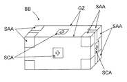
図2は、境界ボックスBBの例を示す。この例では、異なるコントロールがこの対話型境界ボックスと共に利用することができる。コントロールは、ユーザが境界ボックスBBと対話して所定の機能をトリガすることを可能にするコマンドである。 FIG. 2 shows an example of the bounding box BB. In this example, different controls can be utilized with this interactive bounding box. A control is a command that allows the user to interact with the bounding box BB to trigger a predetermined function.
境界ボックスBBは、その表面に、少なくとも1つの選択可能なコンテンツ領域SCAを備える。例えば、平行六面体の境界ボックスBBに関しては、境界ボックスBBの面は、この例にける領域、例えば、その面の中央に、境界ボックスBBにアセンブリのオブジェクトを追加するためのコントロールである部分を備えることができる。この例では、当該領域は表面である。 The bounding box BB comprises on its surface at least one selectable content area SCA. For example, with respect to a parallelepiped bounding box BB, the face of the bounding box BB comprises a region in this example, for example, in the middle of that face, a portion that is a control for adding an object of the assembly to the bounding box BB be able to. In this example, the area is a surface.
境界ボックスBBは、その表面に、少なくとも1つの選択可能な軸領域SAAであって、その軸領域SAAに直交する軸に沿って、別の境界ボックスBBの位置を変更する軸領域SAAをさらに備えることができる。例えば、平行六面体の境界ボックスBBに関しては、境界ボックスBBの面は、例えば、その面の各角に、軸領域に直交する軸に沿って、別の境界ボックスBBの位置を変更するためのコントロールである部分を備えることができる。 The bounding box BB further comprises on its surface an axial area SAA which is at least one selectable axial area SAA and which changes the position of another bounding box BB along an axis orthogonal to the axial area SAA. be able to. For example, with respect to a parallelepiped bounding box BB, the face of the bounding box BB is, for example, a control for changing the position of another bounding box BB along an axis orthogonal to the axial region at each corner of the face. Can be provided.
境界ボックスBBは、例えば、境界ボックスBBの辺のあたりに位置する、グラブゾーンGZ、換言すれば、グラブ領域をさらに備えることができる。 The bounding box BB may, for example, further comprise a grab zone GZ, in other words a grab area, located around the edge of the bounding box BB.
境界ボックスBBのコントロールSCA、SAAは、部分的透明、例えば、半透明で表示することができる。 The controls SCA, SAA of the bounding box BB can be displayed partially transparent, eg translucent.
換言すると、ユーザは、アセンブリのオブジェクトのセットまたはグループの位置を変えるために、境界ボックスの対話コマンドを用いる必要がある。 In other words, the user needs to use bounding box dialog commands to change the position of the set or group of objects in the assembly.
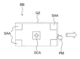
図3aおよび図3bは、本発明の態様に従った方法の例を示す。 Figures 3a and 3b show an example of a method according to an aspect of the present invention.
図3aにおいて、コンピュータマウスを示すポインティング手段PMが、ここでは、画面上に手の形で表されている。ポインティング手段PMは、境界ボックスBBの面であって、当該ポインティング手段PMがアクセスできない対話領域、この例では、対話表面SAA、SCAを有する面に、ユーザによって移動される。ポインティング手段PMは、コンピュータマウス、タッチペン、または、タッチスクリーンであってよい。 In FIG. 3a, pointing means PM, showing a computer mouse, are here represented in the form of hands on the screen. The pointing means PM is moved by the user to the face of the bounding box BB, which is an interactive area to which the pointing means PM can not access, in this example the face with the interactive surfaces SAA, SCA. The pointing means PM may be a computer mouse, a touch pen or a touch screen.
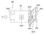
より広い表面WSの表示は自動的に行われ、ポインティング手段PMが当該より広い表面WSでホバリングする限り、表示され続ける。より広い表面は、対話領域SAA、SCAと共に、部分透明の例として、この例では、半透明で表示されている。 The display of the wider surface WS is performed automatically and continues to be displayed as long as the pointing means PM hovers over the wider surface WS. The wider surface is displayed as semitransparent in this example as an example of partial transparency together with the interaction areas SAA, SCA.
境界ボックスBBの面は、当該面の少なくとも1つの寸法が、閾値、典型的には20ピクセルより小さい場合、ポインティング手段PMがアクセスできない複数の対話表面を含むとみなされる。一例においては、閾値は、典型的には、対応する寸法に沿って、対話領域のサイズの3倍に等しくすることができる。 The face of the bounding box BB is considered to include a plurality of interactive surfaces which the pointing means PM can not access if at least one dimension of the face is smaller than a threshold, typically 20 pixels. In one example, the threshold may be equal to three times the size of the interaction area, typically along the corresponding dimension.
例えば、より広い表面WSは、ポインティング手段PMがアクセスできない面を含む平面に表示され、ポインティング手段PMがアクセスできない面の寸法に沿って、ポインティング手段PMがアクセスできない面の中心に置かれる。当然、これらの特徴は、各々単独でまたは組み合わせて用いることができる。 For example, the wider surface WS is displayed on a plane that includes the surface that the pointing device PM can not access, and is centered on the surface that the pointing device PM can not access along the dimensions of the surface that the pointing device PM can not access. Of course, these features can each be used alone or in combination.
図4は、本発明を実施可能なコンピュータネットワークまたは類似のデジタル処理環境を示す。 FIG. 4 illustrates a computer network or similar digital processing environment in which the present invention may be implemented.
1つまたは複数のクライアントコンピュータ/デバイスCLおよび1つまたは複数のサーバコンピュータSVは、アプリケーションプログラムなどを実行するための処理装置、記憶装置、および入/出力装置を提供する。1つまたは複数のクライアントコンピュータ/デバイスCLはまた、通信ネットワークCNETを介して、他のクライアントデバイス/プロセッサCLおよび1つまたは複数のサーバコンピュータSVを含む、他のコンピュータデバイスとリンクさせることができる。通信ネットワーク70は、現在、各プロトコル(TCP/IP、Bluetooth(登録商標)など)を用いて互いに通信する、リモートアクセスネットワーク、グローバルネットワーク(例えば、インターネット)、世界規模のコンピュータの集合体(a worldwide collection of computers)、ローカルエリアネットワークまたは広域ネットワーク、およびゲートウェイの一部であってよい。他の電子デバイス/コンピュータのネットワークアーキテクチャも適合する。 One or more client computers / devices CL and one or more server computers SV provide processing devices, storage devices, and input / output devices for executing application programs and the like. One or more client computers / devices CL can also be linked via the communication network CNET to other computing devices, including other client devices / processors CL and one or more server computers SV. The communication network 70 currently communicates with each other using each protocol (TCP / IP, Bluetooth (registered trademark), etc.), a remote access network, a global network (eg, the Internet), a collection of computers on a global scale (a worldwide) It may be part of a collection of computers), a local area network or wide area network, and a gateway. Other electronic device / computer network architectures are also compatible.
図5は、図4のコンピュータシステム内のコンピュータ(例えば、クライアントプロセッサ/デバイスCLまたはサーバコンピュータSV)の内部構造の図である。各コンピュータCL、SVは、システムバスSBを含む。ここで、バスは、コンピュータまたは処理システムのコンポーネント間でのデータ転送に用いされるハードウェアの配線のセットである。バスSBは、基本的に、コンピュータシステムの異なる要素(例えば、プロセッサ、ディスク記憶装置、メモリ、入力/出力ポート、ネットワークポートなど)を接続する共有のコンジットで、要素間の情報の転送を可能にする。 5 is a diagram of the internal structure of a computer (eg, client processor / device CL or server computer SV) in the computer system of FIG. Each computer CL, SV includes a system bus SB. Here, a bus is a set of hardware wiring used to transfer data between components of a computer or processing system. The bus SB is basically a shared conduit connecting different elements of the computer system (e.g. processor, disk storage, memory, input / output port, network port etc), enabling the transfer of information between the elements Do.
システムバスSBに取り付けられるものには、様々な入力装置および出力装置(例えば、キーボード、マウス、ディスプレイ、プリンタ、スピーカなど)をコンピュータCL、SVに接続するI/O装置インタフェースDIがある。ネットワークインタフェースNIによって、コンピュータはネットワーク(例えば、図4のネットワークCNET)に取り付けられた様々な他の装置に接続することができる。 Attached to the system bus SB is an I / O device interface DI that connects various input devices and output devices (eg, a keyboard, a mouse, a display, a printer, a speaker, etc.) to the computer CL, SV. Network interface NI allows a computer to be connected to various other devices attached to a network (eg, network CNET in FIG. 4).
メモリMEMは、本発明の一実施形態を実施するのに使われるコンピュータソフトウェア命令SIおよびデータCPP(例えば、第1のパスビルダPB、第2のパスを計算する手段CM、図1から図3に関して述べた方法を実施するアップデイタUD、および、上記に詳しく記載したサポートコード)のための揮発性記憶装置を提供する。 The memory MEM is a computer software instruction SI and data CPP (eg, a first pass builder PB, means for calculating a second pass CM) used to implement an embodiment of the invention, described with respect to FIGS. 1 to 3 The present invention provides an updater UD implementing the method and volatile storage for the support code described in detail above.
ディスク記憶装置DSは、本発明の一実施形態を実施するのに使われるコンピュータソフトウェア命令SIおよびデータDATのための不揮発性記憶装置を提供する。中央処理装置CPUもシステムバスSBに接続され、コンピュータ命令を実行する。 The disk storage device DS provides non-volatile storage for computer software instructions SI and data DAT used to implement an embodiment of the present invention. The central processing unit CPU is also connected to the system bus SB and executes computer instructions.
一実施形態においては、プロセッサルーチンSIおよびデータDATは、本発明のシステムのためのソフトウェア命令の少なくとも一部を提供するコンピュータ可読媒体(例えば、1つまたは複数のDVD−ROM、CD−ROM、ディスケット、テープなどの、取り外し可能な記憶媒体)を含むコンピュータプログラム製品(一般にCPPと呼ぶ)である。コンピュータプログラム製品CPPは、本技術分野における当業者には周知のように、任意の適切なソフトウエアインストール手順で、インストールすることができる。 In one embodiment, processor routines SI and data DAT are computer readable media (eg, one or more DVD-ROMs, CD-ROMs, diskettes) that provide at least a portion of software instructions for a system of the present invention. , A removable storage medium such as a tape) (generally referred to as CPP). Computer program product CPP can be installed with any suitable software installation procedure, as is known to those skilled in the art.
別の実施形態においては、ソフトウェア命令の少なくとも一部は、有線通信および/または無線接続を介してダウンロードしてもよい。他の実施形態においては、本発明のプログラムは、伝播媒体(例えば、電波、赤外線波、レーザー波、音波、または、インターネットもしくは他のネットワークなどのグローバルネットワークを介して伝播される電波)で伝播される信号として具現されるコンピュータプログラム伝播信号製品SPである。このような搬送媒体または信号は、本発明のルーチン/プログラムCPPのためのソフトウェア命令の少なくとも一部を提供する。 In another embodiment, at least a portion of the software instructions may be downloaded via a wired communication and / or a wireless connection. In another embodiment, the program of the present invention is propagated in a propagation medium (eg, radio waves, infrared waves, laser waves, sound waves, or radio waves propagated through a global network such as the Internet or other networks) Computer program propagation signal product SP embodied as a signal. Such carrier medium or signal provides at least a part of software instructions for the routine / program CPP of the present invention.
代替的な実施形態においては、伝播される信号は、アナログの搬送波、または、伝播媒体に搬送されるデジタル信号である。例えば、伝播される信号は、グローバルネットワーク(例えば、インターネット)、電気通信網、または、他のネットワークを介して伝播されるデジタル化された信号であってよい。 In alternative embodiments, the propagated signal is an analog carrier or a digital signal carried on a propagation medium. For example, the propagated signal may be a digitized signal propagated through a global network (eg, the Internet), a telecommunications network, or other networks.
一実施形態においては、伝播される信号は、一定の期間にわたって伝播媒体を介して送信される信号、例えば、ミリ秒、秒、分、または、より長い時間にわたって、ネットワークを介してパケットの形で送信されるソフトウェアアプリケーションのための命令などである。 In one embodiment, the propagated signal is a signal transmitted through the propagation medium for a fixed period of time, for example, in the form of packets over the network for milliseconds, seconds, minutes, or longer. Such as instructions for the software application to be sent.
別の実施形態においては、コンピュータプログラム伝播信号製品に関して上述したように、コンピュータプログラム製品CPPのコンピュータ可読媒体は、コンピュータシステムCLが、例えば、伝播媒体を受信して、伝播媒体に具現された伝播信号を識別することによって、受信、読み取り可能な伝播媒体である
一般に、「搬送媒体」という用語、すなわち、一時的な搬送波は、前述の過渡信号、伝播信号、伝播媒体、記憶媒体などを含む。
In another embodiment, as described above with respect to the computer program propagation signal product, the computer readable medium of the computer program product CPP is a propagation signal embodied in the propagation medium, for example the computer system CL receiving the propagation medium In general, the term "carrier medium", ie, the temporary carrier, includes the aforementioned transient signals, propagation signals, propagation media, storage media, and the like.
実施形態例に関して本発明を詳細に示し、および説明したが、添付された特許請求の範囲に包含される本発明の範囲を逸脱することなく、形態および詳細に関する様々な変更を行い得ることを当業者は理解されよう。 While the invention has been shown and described in detail with respect to example embodiments, it is understood that various changes in form and detail may be made without departing from the scope of the invention as encompassed by the appended claims. The vendor will be understood.
Claims (11)
少なくとも1つの3次元オブジェクトを取り囲む3次元境界ボックス(BB)であって、前記境界ボックス(BB)の表面の面が、前記面の一部である複数の対話領域を備える3次元境界ボックス(BB)を表示するステップと、
ポインティング手段(PM)を前記境界ボックス(BB)上でホバリングするステップと、
前記境界ボックス(BB)の前記表面の少なくとも1つの面が、前記少なくとも1つの面の対話領域に前記ポインティング手段(PM)がアクセスできないように表示される場合、前記対話領域へのアクセスを可能とする、より広い表面(WS)を表示するステップとを備える方法。 A computer-implemented method for manipulating a three-dimensional modeled object of an assembly in a three-dimensional scene, comprising:
A three-dimensional bounding box (BB) surrounding at least one three-dimensional object, the surface of the bounding box (BB) comprising a plurality of interactive areas being part of the surface Step of displaying
Hovering pointing means (PM) on said bounding box (BB);
Allow access to the dialogue area if at least one face of the surface of the bounding box (BB) is displayed such that the pointing means (PM) can not access the dialogue area of the at least one face Displaying a wider surface (WS).
Applications Claiming Priority (2)
| Application Number | Priority Date | Filing Date | Title |
|---|---|---|---|
| EP13165965.8 | 2013-04-30 | ||
| EP13165965.8A EP2800020B1 (en) | 2013-04-30 | 2013-04-30 | A computer-implemented method for manipulating three-dimensional modeled objects of an assembly in a three-dimensional scene. |
Publications (3)
| Publication Number | Publication Date |
|---|---|
| JP2014219976A JP2014219976A (en) | 2014-11-20 |
| JP2014219976A5 JP2014219976A5 (en) | 2017-04-27 |
| JP6510182B2 true JP6510182B2 (en) | 2019-05-08 |
Family
ID=48227016
Family Applications (1)
| Application Number | Title | Priority Date | Filing Date |
|---|---|---|---|
| JP2014092822A Active JP6510182B2 (en) | 2013-04-30 | 2014-04-28 | A method implemented by a computer to manipulate a 3D modeled object of an assembly in a 3D scene |
Country Status (5)
| Country | Link |
|---|---|
| US (1) | US9710131B2 (en) |
| EP (1) | EP2800020B1 (en) |
| JP (1) | JP6510182B2 (en) |
| KR (1) | KR20140130061A (en) |
| CA (1) | CA2850828A1 (en) |
Families Citing this family (6)
| Publication number | Priority date | Publication date | Assignee | Title |
|---|---|---|---|---|
| US10146299B2 (en) * | 2013-11-08 | 2018-12-04 | Qualcomm Technologies, Inc. | Face tracking for additional modalities in spatial interaction |
| EP3528909B1 (en) | 2016-10-20 | 2022-06-29 | Osipov, Ilya | Electrical connector |
| RU2644313C1 (en) * | 2017-02-23 | 2018-02-08 | Кубиос Инк. | Electronic device with volumetric transformable display |
| US11000772B2 (en) | 2016-10-20 | 2021-05-11 | Cubios, Inc. | Electronic device with a three-dimensional transformable display |
| RU181175U1 (en) * | 2018-02-22 | 2018-07-05 | Ирина Алексеевна Баранова | Multimedia surround gaming device |
| RU2723664C1 (en) * | 2020-01-06 | 2020-06-17 | Илья Викторович Осипов | Electronic device with volumetric transformable display (versions) |
Family Cites Families (34)
| Publication number | Priority date | Publication date | Assignee | Title |
|---|---|---|---|---|
| US5490241A (en) * | 1989-10-06 | 1996-02-06 | Xerox Corporation | Interactive computer graphics system for making precise drawings |
| US5583977A (en) * | 1993-10-21 | 1996-12-10 | Taligent, Inc. | Object-oriented curve manipulation system |
| US6006227A (en) * | 1996-06-28 | 1999-12-21 | Yale University | Document stream operating system |
| AU4190900A (en) * | 1999-04-06 | 2000-10-23 | Microsoft Corporation | Method and apparatus for supporting two-dimensional windows in a three-dimensional environment |
| US7312796B1 (en) * | 2000-05-08 | 2007-12-25 | Jlb Ventures Llc | Perpendicular view three dimensional electronic programming guide |
| US7266768B2 (en) * | 2001-01-09 | 2007-09-04 | Sharp Laboratories Of America, Inc. | Systems and methods for manipulating electronic information using a three-dimensional iconic representation |
| US7246329B1 (en) * | 2001-05-18 | 2007-07-17 | Autodesk, Inc. | Multiple menus for use with a graphical user interface |
| US7480873B2 (en) * | 2003-09-15 | 2009-01-20 | Sun Microsystems, Inc. | Method and apparatus for manipulating two-dimensional windows within a three-dimensional display model |
| US20050248560A1 (en) * | 2004-05-10 | 2005-11-10 | Microsoft Corporation | Interactive exploded views from 2D images |
| JP2006215814A (en) * | 2005-02-03 | 2006-08-17 | Ricoh Co Ltd | Static image creation method, static image creation device and recording medium |
| US7880737B2 (en) * | 2005-03-22 | 2011-02-01 | Vijayvardhan Elchuri | Graphical method and system for making drawings directly in three-dimensions on a computer monitor or other display device |
| JP5160431B2 (en) * | 2005-10-20 | 2013-03-13 | コーニンクレッカ フィリップス エレクトロニクス エヌ ヴィ | Game with programmable luminous segments |
| EP1901235B1 (en) * | 2006-09-15 | 2019-08-14 | Honda Research Institute Europe GmbH | Free style deformation (FSD) |
| US20080094398A1 (en) * | 2006-09-19 | 2008-04-24 | Bracco Imaging, S.P.A. | Methods and systems for interacting with a 3D visualization system using a 2D interface ("DextroLap") |
| US9086785B2 (en) * | 2007-06-08 | 2015-07-21 | Apple Inc. | Visualization object receptacle |
| US8745535B2 (en) * | 2007-06-08 | 2014-06-03 | Apple Inc. | Multi-dimensional desktop |
| US8601392B2 (en) * | 2007-08-22 | 2013-12-03 | 9224-5489 Quebec Inc. | Timeline for presenting information |
| US20090125801A1 (en) * | 2007-11-10 | 2009-05-14 | Cherif Atia Algreatly | 3D windows system |
| US8745536B1 (en) * | 2008-11-25 | 2014-06-03 | Perceptive Pixel Inc. | Volumetric data exploration using multi-point input controls |
| US8132120B2 (en) * | 2008-12-29 | 2012-03-06 | Verizon Patent And Licensing Inc. | Interface cube for mobile device |
| EP2261827B1 (en) * | 2009-06-10 | 2015-04-08 | Dassault Systèmes | Process, program and apparatus for displaying an assembly of objects of a PLM database |
| JP2011044358A (en) * | 2009-08-21 | 2011-03-03 | Panasonic Electric Works Co Ltd | Lighting simulator |
| TW201140420A (en) * | 2010-06-15 | 2011-11-16 | Wistron Neweb Corp | User interface and electronic device |
| US8537157B2 (en) * | 2010-06-21 | 2013-09-17 | Verizon Patent And Licensing Inc. | Three-dimensional shape user interface for media content delivery systems and methods |
| WO2011160196A2 (en) * | 2010-06-24 | 2011-12-29 | Associação Instituto Nacional De Matemática Pura E Aplicada | Multidimensional-data-organization method |
| US8443300B2 (en) * | 2010-08-24 | 2013-05-14 | Ebay Inc. | Three dimensional navigation of listing information |
| US8465356B2 (en) * | 2010-11-22 | 2013-06-18 | Gonzalez Rosendo | Display puzzle |
| US9785289B2 (en) * | 2010-11-23 | 2017-10-10 | Red Hat, Inc. | GUI control improvement using a capacitive touch screen |
| KR20120066846A (en) * | 2010-12-15 | 2012-06-25 | 삼성전자주식회사 | Mobile device |
| EP2699986B1 (en) * | 2011-04-19 | 2019-03-20 | Hewlett-Packard Development Company, L.P. | Touch screen selection |
| US20130047100A1 (en) * | 2011-08-17 | 2013-02-21 | Google Inc. | Link Disambiguation For Touch Screens |
| US8497859B1 (en) * | 2012-04-03 | 2013-07-30 | Google Inc. | Display of information on or within a three-dimensional image |
| US20130321461A1 (en) * | 2012-05-29 | 2013-12-05 | Google Inc. | Method and System for Navigation to Interior View Imagery from Street Level Imagery |
| US10241638B2 (en) * | 2012-11-02 | 2019-03-26 | Atheer, Inc. | Method and apparatus for a three dimensional interface |
-
2013
- 2013-04-30 EP EP13165965.8A patent/EP2800020B1/en active Active
-
2014
- 2014-04-10 US US14/250,344 patent/US9710131B2/en active Active
- 2014-04-28 JP JP2014092822A patent/JP6510182B2/en active Active
- 2014-04-29 CA CA 2850828 patent/CA2850828A1/en not_active Abandoned
- 2014-04-29 KR KR1020140051895A patent/KR20140130061A/en not_active Application Discontinuation
Also Published As
| Publication number | Publication date |
|---|---|
| JP2014219976A (en) | 2014-11-20 |
| EP2800020A1 (en) | 2014-11-05 |
| EP2800020B1 (en) | 2020-11-04 |
| CN104133928A (en) | 2014-11-05 |
| US20140325413A1 (en) | 2014-10-30 |
| KR20140130061A (en) | 2014-11-07 |
| CA2850828A1 (en) | 2014-10-30 |
| US9710131B2 (en) | 2017-07-18 |
Similar Documents
| Publication | Publication Date | Title |
|---|---|---|
| JP6510182B2 (en) | A method implemented by a computer to manipulate a 3D modeled object of an assembly in a 3D scene | |
| JP6495589B2 (en) | A computer-implemented method for determining the exploded path of an exploded view of an assembly of 3D modeled objects | |
| US10162491B2 (en) | Drag and drop of objects between applications | |
| US10984606B1 (en) | Graphical user interface tool for orienting computer-aided design model | |
| JP6534974B2 (en) | System and method for providing an efficient interface for screen control | |
| JP6510181B2 (en) | Method implemented by a computer for manipulating a 3D modeled object of an assembly in a 3D scene | |
| AU2016277556B2 (en) | 3d digital content interaction and control | |
| JP6401046B2 (en) | Computer-implemented method for designing 3D modeled objects | |
| US10964122B2 (en) | Snapping virtual object to target surface | |
| JP6945270B2 (en) | How to run a computer to set a tool with at least one pointing element on the screen | |
| Cao et al. | Research and Implementation of virtual pottery | |
| JP2024513665A (en) | Methods, systems and programs to calibrate systems including cameras | |
| Runde et al. | A multi server multi user approach for distributed virtual environments | |
| NZ709107B2 (en) | Drag and drop of objects between applications | |
| NZ619935B2 (en) | Drag and drop of objects between applications |
Legal Events
| Date | Code | Title | Description |
|---|---|---|---|
| A521 | Request for written amendment filed |
Free format text: JAPANESE INTERMEDIATE CODE: A523 Effective date: 20170321 |
|
| A621 | Written request for application examination |
Free format text: JAPANESE INTERMEDIATE CODE: A621 Effective date: 20170321 |
|
| A131 | Notification of reasons for refusal |
Free format text: JAPANESE INTERMEDIATE CODE: A131 Effective date: 20180515 |
|
| A601 | Written request for extension of time |
Free format text: JAPANESE INTERMEDIATE CODE: A601 Effective date: 20180815 |
|
| A521 | Request for written amendment filed |
Free format text: JAPANESE INTERMEDIATE CODE: A523 Effective date: 20181015 |
|
| TRDD | Decision of grant or rejection written | ||
| A01 | Written decision to grant a patent or to grant a registration (utility model) |
Free format text: JAPANESE INTERMEDIATE CODE: A01 Effective date: 20190312 |
|
| A61 | First payment of annual fees (during grant procedure) |
Free format text: JAPANESE INTERMEDIATE CODE: A61 Effective date: 20190404 |
|
| R150 | Certificate of patent or registration of utility model |
Ref document number: 6510182 Country of ref document: JP Free format text: JAPANESE INTERMEDIATE CODE: R150 |
|
| R250 | Receipt of annual fees |
Free format text: JAPANESE INTERMEDIATE CODE: R250 |
|
| R250 | Receipt of annual fees |
Free format text: JAPANESE INTERMEDIATE CODE: R250 |