JP6505393B2 - Medical observation device and medical observation system - Google Patents
Medical observation device and medical observation system Download PDFInfo
- Publication number
- JP6505393B2 JP6505393B2 JP2014168842A JP2014168842A JP6505393B2 JP 6505393 B2 JP6505393 B2 JP 6505393B2 JP 2014168842 A JP2014168842 A JP 2014168842A JP 2014168842 A JP2014168842 A JP 2014168842A JP 6505393 B2 JP6505393 B2 JP 6505393B2
- Authority
- JP
- Japan
- Prior art keywords
- unit
- arm
- axis
- observation
- joint
- Prior art date
- Legal status (The legal status is an assumption and is not a legal conclusion. Google has not performed a legal analysis and makes no representation as to the accuracy of the status listed.)
- Active
Links
Images


Classifications
-
- G—PHYSICS
- G02—OPTICS
- G02B—OPTICAL ELEMENTS, SYSTEMS OR APPARATUS
- G02B21/00—Microscopes
- G02B21/0004—Microscopes specially adapted for specific applications
- G02B21/0012—Surgical microscopes
-
- A—HUMAN NECESSITIES
- A61—MEDICAL OR VETERINARY SCIENCE; HYGIENE
- A61B—DIAGNOSIS; SURGERY; IDENTIFICATION
- A61B90/00—Instruments, implements or accessories specially adapted for surgery or diagnosis and not covered by any of the groups A61B1/00 - A61B50/00, e.g. for luxation treatment or for protecting wound edges
- A61B90/20—Surgical microscopes characterised by non-optical aspects
- A61B90/25—Supports therefor
-
- G—PHYSICS
- G02—OPTICS
- G02B—OPTICAL ELEMENTS, SYSTEMS OR APPARATUS
- G02B7/00—Mountings, adjusting means, or light-tight connections, for optical elements
- G02B7/001—Counterbalanced structures, e.g. surgical microscopes
-
- A—HUMAN NECESSITIES
- A61—MEDICAL OR VETERINARY SCIENCE; HYGIENE
- A61B—DIAGNOSIS; SURGERY; IDENTIFICATION
- A61B90/00—Instruments, implements or accessories specially adapted for surgery or diagnosis and not covered by any of the groups A61B1/00 - A61B50/00, e.g. for luxation treatment or for protecting wound edges
- A61B90/36—Image-producing devices or illumination devices not otherwise provided for
- A61B90/37—Surgical systems with images on a monitor during operation
- A61B2090/373—Surgical systems with images on a monitor during operation using light, e.g. by using optical scanners
-
- G—PHYSICS
- G02—OPTICS
- G02B—OPTICAL ELEMENTS, SYSTEMS OR APPARATUS
- G02B21/00—Microscopes
- G02B21/36—Microscopes arranged for photographic purposes or projection purposes or digital imaging or video purposes including associated control and data processing arrangements
- G02B21/365—Control or image processing arrangements for digital or video microscopes
Landscapes
- Physics & Mathematics (AREA)
- Health & Medical Sciences (AREA)
- Surgery (AREA)
- General Physics & Mathematics (AREA)
- Optics & Photonics (AREA)
- General Health & Medical Sciences (AREA)
- Life Sciences & Earth Sciences (AREA)
- Chemical & Material Sciences (AREA)
- Analytical Chemistry (AREA)
- Engineering & Computer Science (AREA)
- Pathology (AREA)
- Oral & Maxillofacial Surgery (AREA)
- Nuclear Medicine, Radiotherapy & Molecular Imaging (AREA)
- Biomedical Technology (AREA)
- Heart & Thoracic Surgery (AREA)
- Medical Informatics (AREA)
- Molecular Biology (AREA)
- Animal Behavior & Ethology (AREA)
- Public Health (AREA)
- Veterinary Medicine (AREA)
- Microscoopes, Condenser (AREA)
- Multimedia (AREA)
- Computer Vision & Pattern Recognition (AREA)
Description
本発明は、被観察体の微小部位を観察する医療用観察装置および医療用観察システムに関する。 The present invention relates to a medical observation apparatus and a medical observation system for observing a minute region of an object to be observed.
従来、被観察体である患者の脳や心臓等における微小部位の手術を行う際に該微小部位を観察するための技術として、該微小部位を撮像し、撮像した画像をモニタで表示する技術が知られている。 Heretofore, as a technique for observing a minute site in surgery on a minute site in a patient's brain or heart as an object to be observed, a technique for imaging the minute site and displaying the imaged image on a monitor has been proposed. Are known.
例えば、特許文献1では、対物光学系を有する観察装置と、この対物光学系に入射した光学像を撮像する撮像装置と、観察装置および撮像装置を保持して連動させる移動機構とを備えた観察システムが開示されている。
For example, in
また、特許文献2には、対物光学系、撮像光学系、およびそれら2つの光学系の間に設けられる変倍光学系を有し、変倍光学系が折り曲げ光学系として構成されるC字状の鏡体部と、この鏡体部を移動可能に支持する支持手段とを備えた医療用観察装置が開示されている。
In addition,
医療用の観察装置では、操作のしやすさに対する要求と同時に、ユーザである術者の視野を確保したり省スペース化を実現したりするために装置の小型化に関する要求も強くなってきている。しかしながら、上述した特許文献1、2では、観察および撮像機能を有する先端部または鏡体部を移動させる機構がリンク機構等を用いて構成されるため、構造が複雑で大がかりにならざるを得ず、その先端部または鏡体部を操作する際の操作性が良好であるとは言い難かった。また、特許文献2の場合、鏡体部の構成自体も小型化する上での障害となっていた。
In the medical observation apparatus, in addition to the demand for ease of operation, the demand for downsizing of the apparatus is also increasing in order to secure the field of view of the operator who is the user and to realize space saving. . However, in the
本発明は、上記に鑑みてなされたものであって、操作性に優れて小型化にも好適な医療用観察装置および医療用観察システムを提供することを目的とする。 This invention is made in view of the above, Comprising: It aims at providing the medical observation apparatus and medical observation system which were excellent in operativity and suitable also for size reduction.
上述した課題を解決し、目的を達成するために、本発明に係る医療用観察装置は、被観察体からの光を高さ方向の一端を介して集光して該被観察体の微小部位の拡大画像を撮像する顕微鏡部であって移動する際にユーザによって把持される柱状をなす顕微鏡部を有し、重心が前記高さ方向の中心よりも前記一端から遠くに位置する観察部と、前記観察部を、前記重心または該重心の近傍を通過して前記高さ方向と垂直な軸のまわりに回動可能に支持する支持部と、を備えたことを特徴とする。 In order to solve the problems described above and to achieve the object, the medical observation apparatus according to the present invention condenses light from an object to be observed through one end in the height direction to form a minute region of the object to be observed An observation unit having a columnar microscope unit which is grasped by a user when moving, and whose center of gravity is located farther from the one end than the center in the height direction; And a support portion rotatably supporting the observation portion around an axis perpendicular to the height direction, passing through the gravity center or the vicinity of the gravity center.
本発明に係る医療用観察装置は、上記発明において、前記観察部は、前記重心と前記一端との距離が、前記観察部の高さの1/2より大きく、かつ前記観察部の高さの2/3以下であることを特徴とする。 In the medical observation apparatus according to the present invention, in the above-mentioned invention, in the observation section, the distance between the center of gravity and the one end is larger than half of the height of the observation section and the height of the observation section It is characterized by being 2/3 or less.
本発明に係る医療用観察装置は、上記発明において、前記観察部は、前記顕微鏡部を前記高さ方向に沿った第1軸のまわりに回動可能に保持する第1関節部と、先端部で前記第1関節部を保持するとともに、基端部で前記高さ方向と垂直な軸であって前記第1軸と直交する軸である第2軸のまわりに回動可能な態様で前記支持部に保持される第1アーム部と、をさらに有し、前記重心は、前記第1軸と前記第2軸の交点に位置する、または該交点より前記一端から近くに位置することを特徴とする。 In the medical observation apparatus according to the present invention as set forth in the invention described above, the observation section includes a first joint section rotatably holding the microscope section around a first axis along the height direction, and a tip section. And supporting the first joint in a rotatable manner about a second axis which is an axis perpendicular to the height direction at the base end and perpendicular to the first axis. And a first arm portion held by a portion, wherein the center of gravity is located at an intersection of the first axis and the second axis, or is located closer to the one end than the intersection. Do.
本発明に係る医療用観察装置は、上記発明において、前記第1アーム部は、前記第2軸を通過するとともに前記第1軸と直交する平面に対して前記一端側に位置する第1部分の比重が前記平面に対して前記第1部分と反対側に位置する第2部分の比重より小さいことを特徴とする。 In the medical observation apparatus according to the present invention as set forth in the invention described above, the first arm portion is a portion of the first portion located on the one end side with respect to a plane passing through the second axis and orthogonal to the first axis. The specific gravity is smaller than the specific gravity of the second portion located on the opposite side to the first portion with respect to the plane.
本発明に係る医療用観察装置は、上記発明において、前記観察部は、前記顕微鏡部の側面に設けられ、前記重心よりも前記一端の近くに位置し、前記顕微鏡部に対する動作指示の入力を受け付ける入力部をさらに有することを特徴とする。 In the medical observation apparatus according to the present invention as set forth in the invention described above, the observation section is provided on a side surface of the microscope section, is positioned closer to the one end than the center of gravity, and receives an input of operation instructions to the microscope section. It is characterized by further having an input part.
本発明に係る医療用観察装置は、上記発明において、前記支持部は、2つのアーム部および該2つのアーム部の一方を他方に対して回動可能に連結する関節部からなる組を少なくとも一組有することを特徴とする。 In the medical observation apparatus according to the present invention as set forth in the invention described above, the support portion includes at least one set of two arm portions and a joint portion pivotally connecting one of the two arm portions to the other. It is characterized by having a set.
本発明に係る医療用観察システムは、上記に記載の医療用観察装置と、前記医療用観察装置が出力した撮像信号に対して信号処理を施して表示用の画像データを生成する制御装置と、前記制御装置が生成した画像データに対応する画像を表示する表示装置と、を備えたことを特徴とする。 A medical observation system according to the present invention includes: the medical observation device described above; and a control device that performs signal processing on an imaging signal output from the medical observation device to generate display image data. And a display device for displaying an image corresponding to the image data generated by the control device.
本発明によれば、被観察体からの光を高さ方向の一端を介して集光して該被観察体の微小部位の拡大画像を撮像する顕微鏡部であって移動する際にユーザによって把持される柱状をなす顕微鏡部を有し、重心が高さ方向の中心よりも一端から遠くに位置する観察部と、観察部を重心または該重心の近傍を通過して高さ方向と垂直な軸のまわりに回動可能に支持する支持部と、を備えるため、観察部を大きくすることなく、ユーザが把持する部分を十分に確保することができる。したがって、操作性に優れて小型化にも好適な医療用観察装置および医療用観察システムを提供することができる。 According to the present invention, the light from the object to be observed is collected through one end in the height direction, and the microscope unit captures an enlarged image of a minute region of the object to be observed. And an observation unit whose center of gravity is located farther from one end than the center in the height direction, and an axis perpendicular to the height direction passing through the center of gravity or the vicinity of the center of gravity. And a support portion rotatably supported around the portion, so that a portion to be gripped by the user can be sufficiently secured without enlarging the observation portion. Therefore, it is possible to provide a medical observation apparatus and a medical observation system which are excellent in operability and suitable for miniaturization.
以下、添付図面を参照して、本発明を実施するための形態(以下、「実施の形態」という)を説明する。なお、図面はあくまで模式的なものであり、図面の相互間においても互いの寸法の関係や比率が異なる部分が含まれる場合がある。 Hereinafter, a mode for carrying out the present invention (hereinafter, referred to as “embodiment”) will be described with reference to the attached drawings. Note that the drawings are merely schematic, and there may be portions where the dimensional relationships and ratios differ among the drawings.
(実施の形態1)
図1は、本発明の実施の形態1に係る医療用観察システムの構成を示す図である。同図に示す医療用観察システム1は、被観察体の微細構造を拡大して撮像する顕微鏡としての機能を有する医療用観察装置(以下、観察装置という)2と、医療用観察システム1の動作を統括して制御する制御装置3と、観察装置2が撮像した画像を表示する表示装置4とを備える。
FIG. 1 is a diagram showing the configuration of a medical observation system according to
観察装置2は、被観察体の微小部位を観察する観察部5と、観察部5の基端部に接続し、観察部5を回動可能に支持する支持部6と、支持部6の基端部を回動可能に保持し、床面上を移動可能なベース部7と、を有する。
The
図2は、観察部5とその周辺の構成を示す拡大斜視図である。図3は、図2の矢視A方向の側面図である。矢視A方向は、図2の第1軸O1と直交するとともに第2軸O2と平行な方向である。以下、図2および図3を参照して、観察部5の構成を説明する。
FIG. 2 is an enlarged perspective view showing the configuration of the
観察部5は、被観察体の微小部位を拡大して撮像する顕微鏡部51と、先端側で顕微鏡部51を高さ方向の第1軸O1のまわりに回動可能に保持する第1関節部52と、先端側で第1関節部52を固定して保持する第1アーム部53とを有する。
The
顕微鏡部51は、円筒状をなす筒状部511と、筒状部511の中空部に設けられ、被観察体の像を拡大して撮像する撮像部512と、第1アーム部53および支持部6が有するアーム部(後述)の動きを許容する操作入力を受け付けるアーム操作スイッチ513と、撮像部512における拡大倍率および被観察体までの焦点距離を変更可能な十字レバー514と、を有する。顕微鏡部51は、自身が移動する際にユーザによって把持される柱状をなしている。
The
筒状部511は、第1関節部52よりも径が小さい円筒状をなしており、被観察体からの光を集光する下端の開口面には、撮像部512を保護するカバーガラスが設けられている(図示せず)。なお、筒状部511の形状は円筒状に限られるわけではなく、多角筒状であってもよい。
The
撮像部512は、光軸が第1軸O1と一致するようにそれぞれ配置される複数のレンズを有し、被観察体からの光を集光して結像する光学系515と、光学系515が集光した光を受光して光電変換することによって撮像信号をそれぞれ生成する撮像素子516とを有する。なお、図2では、光学系515が有する複数のレンズを収容する筒状の筐体のみを記載している。
光学系515は、十字レバー514の操作に応じて被観察体像の拡大倍率および被観察体までの焦点距離を変更可能である。
The
撮像素子516は、CCD(Charge Coupled Device)またはCMOS(Complementary Metal Oxide Semiconductor)を用いて構成される。撮像素子516は、撮像信号を生成して出力する。この撮像信号は、支持部6の内部に設けられる伝送ケーブルを介して制御装置3に伝送される。
The
撮像部512は、第1関節部52の内部まで入り込んでいる。図3では、筒状部511および第1関節部52の中空部に設置される光学系515および撮像素子516を1点鎖線で模式的に示している。また、図3では、顕微鏡部51のうち第1関節部52の内部に入り込んで第1関節部52に対して筒状部511とともに回動する部分の境界を2点鎖線で模式的に示している。
The
アーム操作スイッチ513は、押しボタン式のスイッチである。ユーザがアーム操作スイッチ513を押下している間、第1関節部52、ならびに支持部6が有する第2関節部61、第3関節部63、第4関節部65、第5関節部67および第6関節部69の電磁ブレーキが解除される。アーム操作スイッチ513は、顕微鏡部51の操作時にユーザが向かい合う側面と反対側の側面、換言すると顕微鏡部51の操作時にユーザの死角となる側面に設けられる。アーム操作スイッチ513は、顕微鏡部51に対する動作指示の入力を受け付ける入力部の一部をなす。
The
十字レバー514は、筒状部511の高さ方向および該高さ方向と直交する周方向に沿って操作可能である。十字レバー514は、筒状部511の側面であって筒状部511の高さ方向に沿ってアーム操作スイッチ513の下方の側面に設けられる。十字レバー514も、アーム操作スイッチ513と同様に、顕微鏡部51に対する動作指示の入力を受け付ける入力部の一部をなす。
The
十字レバー514を図2に示す状態から筒状部511の高さ方向に沿って操作すると、拡大倍率が変更される。また、十字レバー514を図2に示す状態から筒状部511の周方向に沿って操作すると、被観察体までの焦点距離が変更される。例えば、筒状部511の高さ方向に沿って十字レバー514を上方へ動かすと拡大倍率が大きくなり、筒状部511の高さ方向に沿って十字レバー514を下方へ動かすと拡大倍率が小さくなる。また、筒状部511の周方向に沿って十字レバー514を時計回りに動かすと被観察体までの焦点距離が遠くなり、筒状部511の周方向に沿って十字レバー514を反時計回りに動かすと被観察体までの焦点距離が近くなる。なお、十字レバー514の移動方向と操作の割り当ては、ここで説明したものに限られるわけではない。
When the
第1関節部52は、先端側で顕微鏡部51を回動可能に保持するとともに、基端側で第1アーム部53の先端部に固定された状態で第1アーム部53に保持される。第1関節部52は円筒状をなし、高さ方向の中心軸である第1軸O1のまわりに回動可能に顕微鏡部51を保持する。
The first
第1アーム部53は、第1関節部52の側面上端部から第1軸O1と直交するとともに第1軸O2と平行な方向に延び、途中で斜め方向に向きを変えて第2軸O2へ徐々に近づくように延びる略L字状をなす。
The
以上の構成を有する観察部5の重心Gは、図2に示すように第1軸O1と第2軸O2の交点に位置している。第2軸O2は、顕微鏡部51の筒状部511と第1関節部52との境界を通過する。観察部5の高さをHとし、顕微鏡部51における集光側である下端から重心Gまでの高さをhとすると、2つの高さHおよびhは、関係式H/2<h≦2H/3を満たす。換言すれば、重心Gは、顕微鏡部51の下端に対して第1軸O1の方向の高さの中心および入力部(アーム操作スイッチ513、十字レバー514)よりも遠くに位置している。なお、重心Gは、上記関係式を満たしていれば、第1軸O1と第2軸O2の交点の近傍に位置していてもよく、顕微鏡部51の下端から交点よりも近くに位置していればより好ましい。ここで、第1軸O1と第2軸O2の交点の近傍とは、顕微鏡部51と第2関節部の境界部分の径をLとするとき(図3および後述する図4を参照)、その交点を中心とする半径L/2の球状領域のことであり、より好ましくは、その交点を中心とする半径L/4の球状領域のことであり、さらに好ましくは、その交点を中心とする半径L/8の球状領域のことである。
The center of gravity G of the
以上の構成を有する観察部5において、例えば、第1関節部52の外郭は、真鍮または超硬質合金等の比較的比重が大きい材料を用いて構成される一方、筒状部511の外郭は、アルミニウム等の比較的比重が小さい材料を用いて構成される。
In the
次に、図1を参照して支持部6の構成を説明する。支持部6は、第2関節部61、第2アーム部62、第3関節部63、第3アーム部64、第4関節部65、第4アーム部66、第5関節部67、第5アーム部68、および第6関節部69を有する。支持部6は、2つのアーム部および2つのアーム部の一方(先端側)を他方(基端側)に対して回動可能に連結する関節部からなる組を3組有する。この3組は、具体的には、(第2アーム部62、第3関節部63、第3アーム部64)、(第3アーム部64、第4関節部65、第4アーム部66)、(第4アーム部66、第5関節部67、第5アーム部68)である。
Next, the configuration of the
第2関節部61は、先端側で第1アーム部53を回動可能に保持するとともに、基端側で第2アーム部62の先端部に固定された状態で第2アーム部62に保持される。第2関節部61は円筒状をなしており、第2軸O2のまわりに回動可能に第1アーム部53を保持する。第2アーム部62は略L字状をなし、L字の縦線部分の端部で第2関節部61に連結する。
The second
第3関節部63は、先端側で第2アーム部62のL字の横線部分を回動可能に保持するとともに、基端側で第3アーム部64の先端部に固定された状態で第3アーム部64に保持される。第3関節部63は、円筒状をなしており、高さ方向の中心軸であって第2軸O2と直交する軸であり、かつ第2アーム部62が延びる方向と平行な軸である第3軸O3のまわりに回動可能に第2アーム部62を保持する。第3アーム部64は先端側が円筒状をなしており、基端側に先端側の円筒の高さ方向と直交する方向に貫通する孔部が形成されている。第3アーム部64は、この孔部を介して第4関節部65に回動可能に保持される。
The third
第4関節部65は、先端側で第3アーム部64を回動可能に保持するとともに、基端側で第4アーム部66に固定された状態で第4アーム部66に保持される。第4関節部65は円筒状をなしており、高さ方向の中心軸であって第3軸O3と直交する軸である第4軸O4のまわりに回動可能に第3アーム部64を保持する。
The fourth
第5関節部67は、先端側で第4アーム部66を回動可能に保持するとともに、基端側で第5アーム部68に固定して取り付けられる。第5関節部67は円筒状をなしており、高さ方向の中心軸であって第4軸O4と平行な軸である第5軸O5のまわりに第4アーム部66を回動可能に保持する。第5アーム部68は、L字状をなす部分と、L字の横線部分から下方へ延びる棒状の部分とからなる。第5関節部67は、基端側で第5アーム部68のL字の縦線部分の端部に取り付けられる。
The fifth
第6関節部69は、先端側で第5アーム部68を回動可能に保持するとともに、基端側でベース部7の上面に固定して取り付けられる。第6関節部69は円筒状をなしており、高さ方向の中心軸であって第5軸O5と直交する軸である第6軸O6のまわりに第5アーム部68を回動可能に保持する。第6関節部69の先端側には、第5アーム部68の棒状の部分の基端部が取り付けられる。
The sixth
以上説明した構成を有する支持部6は、顕微鏡部51における並進3自由度および回転3自由度の計6自由度の動きを実現する。
The
第1関節部52、第2関節部61、第3関節部63、第4関節部65、第5関節部67および第6関節部69は、顕微鏡部51、第1アーム部53、第2アーム部62、第3アーム部64、第4アーム部66および第5アーム部68の回動をそれぞれ禁止する電磁ブレーキを有する。各電磁ブレーキは、顕微鏡部51に設けられるアーム操作スイッチ513(後述)が押下された状態で解除され、顕微鏡部51、第1アーム部53、第2アーム部62、第3アーム部64、第4アーム部66および第5アーム部68の回動を許容する。なお、電磁ブレーキの代わりにエアブレーキを適用してもよい。
The first
図4は、ユーザが顕微鏡部51を操作する状況を模式的に示す図である。ユーザは、筒状部511の側面のうち、アーム操作スイッチ513および十字レバー514が設けられる側面(図4の右側面)と反対側の側面(図4の左側面)に対向して顕微鏡部51を操作する。この際、ユーザは、顕微鏡部51を右手101で把持した状態で、アーム操作スイッチ513を人差し指(または中指または薬指)で押下しながら支持部6を操作する。
FIG. 4 is a view schematically showing a situation where the user operates the
このように、ユーザは顕微鏡部51を自然に握ったままアーム操作スイッチ513を押下して支持部6を操作することができる。特に、観察部5における重心Gの位置が観察部5の高さ方向の中心よりも顕微鏡部51の下端から遠くに位置しているため、筒状部511の高さを十分取ることができる。このような形状を有する観察部5によれば、ユーザが把持しやすく、かつ第1軸O1および第2軸O2のまわりの回動操作を容易に行うことが可能となる。
As described above, the user can operate the
また、アーム操作スイッチ513が、顕微鏡部51の側面のうちユーザの死角となる側面(ユーザが向い合う側面と反対側の側面)に設けられるため、ユーザは顕微鏡部51を手で握った状態で、顕微鏡部51を回転したり傾斜させたりしても、アーム操作スイッチ513を押し続ける操作や、アーム操作スイッチ513を押したり離したりする操作を違和感なく行うことができる。
In addition, since the
さらに、ユーザは顕微鏡部51の周囲を手で握るため、光学系515の光軸の方向または顕微鏡部51の撮像視野を直感的に認識することができ、顕微鏡部51を所望の位置へ容易に移動させることができる。
Furthermore, since the user holds the periphery of the
引き続き、医療用観察システム1の構成を説明する。
制御装置3は、観察装置2が出力した撮像信号に所定の信号処理を施すことによって表示用の画像データを生成する。制御装置3は、CPU(Central Processing Unit)、ROM(Read Only Memory)、RAM(Random Access Memory)等を用いて構成される。なお、制御装置3をベース部7の内部に設置して観察装置2と一体化してもよい。
Subsequently, the configuration of the
The control device 3 generates display image data by performing predetermined signal processing on the imaging signal output from the
表示装置4は、制御装置3が生成した画像データを制御装置3から受信し、該画像データに対応する画像を表示する。このような表示装置4は、液晶または有機EL(Electro Luminescence)からなる表示パネルを備える。
The
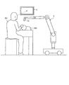
次に、以上の構成を有する医療用観察システム1を用いて行われる手術の概要を説明する。図5は、医療用観察システム1を用いた手術の状況を模式的に示す図である。具体的には、図5は、ユーザである術者201が被観察体である患者202の頭部を手術している状況を模式的に示す図である。術者201は、表示装置4が表示する画像を目視しながら、顕微鏡部51のアーム操作スイッチ513を押下した状態で顕微鏡部51を把持して所望の位置まで移動させ、顕微鏡部51の撮像視野を決定した後、アーム操作スイッチ513から指を離す。これにより、第1関節部52、第2関節部61、第3関節部63、第4関節部65、第5関節部67および第6関節部69では電磁ブレーキが動作し、顕微鏡部51の撮像視野が固定される。その後、術者201は、拡大倍率および被観察体までの焦点距離を調整等を行う。
Next, an outline of the operation performed using the
術者201が顕微鏡部51を把持しやすく、かつ術者201が表示装置4または患者202の術部を見る際の視界の妨げとならないようにするには、例えば筒状部511の外径が40〜70mm程度であり、観察部5の高さ(図3のH)が80〜200mm程度であればより好ましい。
In order to make it easy for the
以上説明した本発明の実施の形態1によれば、被観察体からの光を高さ方向の一端を介して集光して該被観察体の微小部位の拡大画像を撮像する顕微鏡部51であって移動する際にユーザによって把持される柱状をなす顕微鏡部51を有し、重心Gが高さ方向の中心よりも一端から遠くに位置する観察部5と、観察部5を重心Gまたは該重心Gの近傍を通過して高さ方向と垂直な軸(第2軸O2)のまわりに回動可能に支持する支持部6と、を備えるため、重心Gの位置を観察部5の高さ方向の中心からシフトさせることで、観察部5を大きくすることなく、ユーザが把持する部分を十分に確保することができる。したがって、操作性に優れて小型化にも好適な医療用観察装置および医療用観察システムを提供することができる。
According to the first embodiment of the present invention described above, the light from the object to be observed is condensed through one end in the height direction, and the
また、本実施の形態1によれば、観察部5の重心Gと顕微鏡部51の下端との距離を、観察部の高さの1/2より大きく、かつ観察部の高さの2/3以下としたため、ユーザが操作時に把持する部分を確保しつつ、全体の大きさを十分に小型化することができる。
Further, according to the first embodiment, the distance between the center of gravity G of the
また、本実施の形態1によれば、ユーザは顕微鏡部51の筒状部511を手で握って把持するため、光学系515の光軸の方向または顕微鏡部51の撮像視野を直感的に認識することができ、顕微鏡部51を所望の位置へ容易に移動させることができる。この点は、従来の手術用顕微鏡のように、操作信号入力用のスイッチが設けられたグリップが光学系の光軸から離れていて光軸方向を直感的に認識することができない場合と比較して、非常に有利な効果の1つである。
Further, according to the first embodiment, the user grasps the direction of the optical axis of the
また、本実施の形態1によれば、支持部6を複数のアーム部と関節部を連結して構成しているため、従来のようなリンク機構と比べて簡易な構成で観察部5における多様な動きを実現することができる。
Further, according to the first embodiment, since the
(実施の形態2)
図6は、本発明の実施の形態2に係る医療用観察システムが備える観察装置の要部の構成を示す拡大斜視図である。本実施の形態2に係る医療用観察システムは、観察部9の構成が、実施の形態1の観察部5と異なる。観察部5以外の構成は、実施の形態1で説明した医療用観察システム1の構成と同じである。
Second Embodiment
FIG. 6 is an enlarged perspective view showing the configuration of the main part of the observation device provided in the medical observation system according to
観察部9は、顕微鏡部51と、第1関節部91と、第1アーム部92とを有する。顕微鏡部51は、実施の形態1で説明したように、筒状部511、撮像部512、アーム操作スイッチ513、および十字レバー514を有する(図2、図3を参照)。
The observation unit 9 includes a
第1関節部91は円筒状をなしており、先端側で顕微鏡部51を第1軸O1のまわりに回動可能に保持するとともに、基端側で第1アーム部92の先端部に固定された状態で第1アーム部92に保持される。
The first
第1アーム部92は、第1関節部91の側面から第2軸O2に沿って延びる柱状をなす。第1アーム部92は、基端側で第2関節部61に第2軸O2のまわりに回動可能に保持される直方体状の本体部921と、本体部921の側面のうち顕微鏡部51の下端から最も遠い側面に設けられ、顕微鏡部51と制御装置3との間で信号を伝送する複数の伝送ケーブルを収納するケーブル収納部922とを有する。ケーブル収納部922は、真鍮または超硬質合金等の比較的比重が大きい材料を用いて構成される。第1アーム部92は、第2軸O2を通過するとともに第1軸O1と直交する平面に対して、顕微鏡部51の下端側に位置する第1部分の比重が、その反対側に位置してケーブル収納部922を含む第2部分の比重より小さい。
The
観察部9の高さをH’とし、顕微鏡部51の下端から重心Gまでの高さをh’とすると、2つの高さH’およびh’は、関係式H’/2<h’≦2H’/3を満たす。なお、重心Gは、上記関係式を満たしていれば、第1軸O1と第2軸O2の交点の近傍に位置していてもよく、顕微鏡部51の下端から交点よりも近くに位置していればより好ましい。
Assuming that the height of the observation unit 9 is H ′ and the height from the lower end of the
以上説明した本発明の実施の形態2によれば、実施の形態1と同様、操作性に優れて小型化にも好適な医療用観察装置および医療用観察システムを提供することができる。 According to the second embodiment of the present invention described above, as in the first embodiment, it is possible to provide a medical observation apparatus and a medical observation system which are excellent in operability and suitable for downsizing.
また、本実施の形態2によれば、実施の形態1と同様、ユーザが操作時に把持する部分を確保することができるとともに、光学系515の光軸の方向または顕微鏡部51の撮像視野を直感的に認識することができ、顕微鏡部51を所望の位置へ容易に移動させることができる。
Further, according to the second embodiment, as in the first embodiment, it is possible to secure a portion to be gripped by the user at the time of operation, and to intuitively sense the direction of the optical axis of the
また、本実施の形態2によれば、第1アーム部92の本体部921に対して、比較的比重が大きい材料からなるケーブル収納部922を顕微鏡部51の下端から遠い側の側面に設けることにより、第2軸O2を通過するとともに第1軸O1と直交する平面に対して、顕微鏡部51の下端側に位置する第1部分の比重が、その反対側に位置してケーブル収納部922を含む第2部分の比重より小さくしている。これにより、観察部9の重心Gを観察部9の第1軸O1方向の高さの中心よりも顕微鏡部51の一端および入力部から遠くに位置させることができ、観察部5の操作性を向上させることができる。また、ケーブル収納部922は、ケーブル収納機能とおもりの機能を兼備しているため、それぞれ個別に設ける場合と比較して、デザイン上の無駄を省くことができる。
Further, according to the second embodiment, the
(その他の実施の形態)
ここまで、本発明を実施するための形態を説明してきたが、本発明は、上述した実施の形態1、2によってのみ限定されるべきものではない。例えば、撮像部に2つの撮像素子を設けることによって視差を有する2つの画像を撮像し、この2つの画像をもとに3次元画像を生成して表示するようにしてもよい。この場合、ユーザは、3次元画像用の眼鏡を装着して表示装置4が表示する3次元画像を目視することにより、術部を立体的に把握することができる。
(Other embodiments)
Although the embodiments for carrying out the present invention have been described above, the present invention should not be limited only by the above-described first and second embodiments. For example, by providing two imaging elements in the imaging unit, two images having parallax may be taken, and a three-dimensional image may be generated and displayed based on the two images. In this case, the user can three-dimensionally grasp the operative site by wearing the glasses for three-dimensional image and visually observing the three-dimensional image displayed by the
また、支持部6は、2つのアーム部および該2つのアーム部の一方を他方に対して回動可能に連結する関節部からなる組を少なくとも1組有していればよい。
In addition, the
また、筒状部511に設ける操作入力部は上述したものに限られるわけではない。例えば、拡大倍率変更用の操作部と、被観察体までの焦点距離変更用の操作部とを別に設けてもよい。
Moreover, the operation input part provided in the
このように、本発明は、特許請求の範囲に記載した技術的思想を逸脱しない範囲内において、さまざまな実施の形態等を含み得るものである。 Thus, the present invention can include various embodiments and the like without departing from the technical concept described in the claims.
1 医療用観察システム
2、9 医療用観察装置
3 制御装置
4 表示装置
5、9 観察部
6 支持部
7 ベース部
51 顕微鏡部
52、91 第1関節部
53、92 第1アーム部
61 第2関節部
62 第2アーム部
63 第3関節部
64 第3アーム部
65 第4関節部
66 第4アーム部
67 第5関節部
68 第5アーム部
69 第6関節部
511 筒状部
512 撮像部
513 アーム操作スイッチ
514 十字レバー
515 光学系
516 撮像素子
921 本体部
922 ケーブル収納部
DESCRIPTION OF
Claims (7)
前記観察部を、前記重心または該重心の近傍を通過して前記高さ方向と垂直な軸のまわりに回動可能に支持する支持部と、
を備え、
前記観察部は、
前記顕微鏡部を前記高さ方向に沿った第1軸のまわりに回動可能に保持する第1関節部と、
前記第1関節部を保持する第1アーム部であって、前記第1関節部のうち前記一端に対して前記重心より遠くの位置から前記高さ方向と異なる方向へ延び、前記第1軸と直交する軸である第2軸のまわりに回動可能な態様で前記支持部に保持されている第1アーム部と、
を有し、
前記重心は、前記第1軸と前記第2軸の交点の近傍に位置する、または該交点より前記一端から近くに位置する
ことを特徴とする医療用観察装置。 A microscope unit that condenses light from the object to be observed through one end in the height direction to capture a magnified image of a minute region of the object and forms a columnar microscope that is gripped by the user when moving An observation unit having a center, the center of gravity of which is located farther from the one end than the center in the height direction,
A support portion rotatably supporting the observation portion around an axis perpendicular to the height direction passing through the gravity center or the vicinity of the gravity center;
Equipped with
The observation unit
A first joint unit rotatably holding the microscope unit around a first axis along the height direction;
A first arm portion for holding the first joint portion, which extends in a direction different from the height direction from a position farther from the center of gravity with respect to the one end of the first joint portion; A first arm held by the support in a rotatable manner about a second axis which is an orthogonal axis;
Have
The medical observation apparatus , wherein the center of gravity is located near an intersection of the first axis and the second axis, or closer to the one end than the intersection .
前記重心と前記一端との距離が、前記観察部の高さの1/2より大きく、かつ前記観察部の高さの2/3以下であることを特徴とする請求項1に記載の医療用観察装置。 The observation unit
The medical device according to claim 1, wherein the distance between the center of gravity and the one end is larger than 1/2 of the height of the observation part and not more than 2/3 of the height of the observation part. Observation device.
前記第1アーム部を回動可能に保持する第2関節部と、
前記第2関節部を保持するとともに、前記第2軸と直交する方向に延びる第2アーム部と、
を有することを特徴とする請求項1または2に記載の医療用観察装置。 Before Symbol support,
A second joint unit rotatably holding the first arm unit;
A second arm that holds the second joint and extends in a direction orthogonal to the second axis;
The medical observation apparatus according to claim 1 or 2, characterized in that have a.
前記第2軸を通過するとともに前記第1軸と直交する平面に対して前記一端側に位置する第1部分の比重が前記平面に対して前記第1部分と反対側に位置する第2部分の比重より小さいことを特徴とする請求項3に記載の医療用観察装置。 The first arm portion is
A specific gravity of a first portion located on the one end side with respect to a plane passing through the second axis and orthogonal to the first axis is a second portion of the second portion located opposite to the first portion with respect to the plane The medical observation apparatus according to claim 3, wherein the medical observation apparatus has a smaller specific gravity.
前記顕微鏡部の側面に設けられ、前記重心よりも前記一端の近くに位置し、前記顕微鏡部に対する動作指示の入力を受け付ける入力部をさらに有することを特徴とする請求項1〜4のいずれか一項に記載の医療用観察装置。 The observation unit
The input device according to any one of claims 1 to 4, further comprising: an input unit provided on a side surface of the microscope unit, located closer to the one end than the center of gravity and receiving an input of an operation instruction to the microscope unit. The medical observation apparatus as described in a term.
2つのアーム部および該2つのアーム部の一方を他方に対して回動可能に連結する関節部からなる組を少なくとも一組有することを特徴とする請求項1〜5のいずれか一項に記載の医療用観察装置。 The support portion is
6. The apparatus according to any one of claims 1 to 5, characterized in that it has at least one set of two arm parts and an articulation part rotatably connecting one of the two arm parts to the other. Medical observation device.
前記医療用観察装置が出力した撮像信号に対して信号処理を施して表示用の画像データを生成する制御装置と、
前記制御装置が生成した画像データに対応する画像を表示する表示装置と、
を備えたことを特徴とする医療用観察システム。
The medical observation apparatus according to any one of claims 1 to 6,
A control device that performs signal processing on an imaging signal output from the medical observation device to generate display image data;
A display device for displaying an image corresponding to the image data generated by the control device;
The medical observation system characterized by having.
Priority Applications (5)
| Application Number | Priority Date | Filing Date | Title |
|---|---|---|---|
| JP2014168842A JP6505393B2 (en) | 2014-08-21 | 2014-08-21 | Medical observation device and medical observation system |
| US15/328,522 US10634889B2 (en) | 2014-08-21 | 2015-08-13 | Medical observation apparatus and medical observation system |
| CN201580043024.8A CN106659542B (en) | 2014-08-21 | 2015-08-13 | Medical observation device and medical observation system |
| PCT/JP2015/072935 WO2016027749A1 (en) | 2014-08-21 | 2015-08-13 | Medical observation device and medical observation system |
| EP15833815.2A EP3184068A4 (en) | 2014-08-21 | 2015-08-13 | Medical observation device and medical observation system |
Applications Claiming Priority (1)
| Application Number | Priority Date | Filing Date | Title |
|---|---|---|---|
| JP2014168842A JP6505393B2 (en) | 2014-08-21 | 2014-08-21 | Medical observation device and medical observation system |
Related Child Applications (1)
| Application Number | Title | Priority Date | Filing Date |
|---|---|---|---|
| JP2019061563A Division JP6856690B2 (en) | 2019-03-27 | 2019-03-27 | Medical observation device and medical observation system |
Publications (3)
| Publication Number | Publication Date |
|---|---|
| JP2016042981A JP2016042981A (en) | 2016-04-04 |
| JP2016042981A5 JP2016042981A5 (en) | 2017-09-28 |
| JP6505393B2 true JP6505393B2 (en) | 2019-04-24 |
Family
ID=55350694
Family Applications (1)
| Application Number | Title | Priority Date | Filing Date |
|---|---|---|---|
| JP2014168842A Active JP6505393B2 (en) | 2014-08-21 | 2014-08-21 | Medical observation device and medical observation system |
Country Status (5)
| Country | Link |
|---|---|
| US (1) | US10634889B2 (en) |
| EP (1) | EP3184068A4 (en) |
| JP (1) | JP6505393B2 (en) |
| CN (1) | CN106659542B (en) |
| WO (1) | WO2016027749A1 (en) |
Families Citing this family (8)
| Publication number | Priority date | Publication date | Assignee | Title |
|---|---|---|---|---|
| JP6456635B2 (en) * | 2014-09-16 | 2019-01-23 | ソニー・オリンパスメディカルソリューションズ株式会社 | Medical observation apparatus and medical observation system |
| JP7094744B2 (en) * | 2018-03-23 | 2022-07-04 | ソニー・オリンパスメディカルソリューションズ株式会社 | Medical observation device |
| EP3933480A4 (en) | 2019-03-25 | 2022-05-11 | Sony Olympus Medical Solutions Inc. | Medical observation system |
| US20220287551A1 (en) | 2019-08-28 | 2022-09-15 | Sony Olympus Medical Solutions Inc. | Medical image processing apparatus and medical observation system |
| EP4043940A4 (en) | 2019-11-13 | 2022-12-14 | Sony Olympus Medical Solutions Inc. | Light source device and subject observation system |
| CN111150492B (en) * | 2020-01-17 | 2021-04-30 | 长沙理工大学 | Single-degree-of-freedom remote motion center mechanism |
| WO2021166749A1 (en) | 2020-02-18 | 2021-08-26 | ソニー・オリンパスメディカルソリューションズ株式会社 | Learning device and medical image processing device |
| CN116917783A (en) | 2021-03-02 | 2023-10-20 | 索尼奥林巴斯医疗解决方案公司 | Optical connector and medical device |
Family Cites Families (10)
| Publication number | Priority date | Publication date | Assignee | Title |
|---|---|---|---|---|
| DE4334069A1 (en) * | 1993-06-21 | 1995-04-13 | Zeiss Carl Fa | Balanced tripod |
| JP2001051204A (en) * | 1999-05-31 | 2001-02-23 | Asahi Optical Co Ltd | Microscope |
| JP2005013715A (en) | 2003-06-05 | 2005-01-20 | Olympus Corp | Observation system |
| JP2005043458A (en) * | 2003-07-23 | 2005-02-17 | Olympus Corp | Surgical microscope |
| JP4398208B2 (en) * | 2003-09-12 | 2010-01-13 | オリンパス株式会社 | Observation device |
| JP4468710B2 (en) * | 2004-02-12 | 2010-05-26 | オリンパス株式会社 | Medical instrument holding device and medical instrument holding system |
| JP2006014825A (en) | 2004-06-30 | 2006-01-19 | Olympus Corp | Medical observation apparatus |
| JP4728039B2 (en) | 2005-04-28 | 2011-07-20 | オリンパスメディカルシステムズ株式会社 | Medical observation device |
| JP5350675B2 (en) * | 2008-05-15 | 2013-11-27 | オリンパスメディカルシステムズ株式会社 | Medical holding device |
| DE102010043919A1 (en) * | 2010-11-15 | 2012-05-16 | Leica Microsystems (Schweiz) Ag | Portable microscope |
-
2014
- 2014-08-21 JP JP2014168842A patent/JP6505393B2/en active Active
-
2015
- 2015-08-13 EP EP15833815.2A patent/EP3184068A4/en active Pending
- 2015-08-13 CN CN201580043024.8A patent/CN106659542B/en active Active
- 2015-08-13 WO PCT/JP2015/072935 patent/WO2016027749A1/en active Application Filing
- 2015-08-13 US US15/328,522 patent/US10634889B2/en active Active
Also Published As
| Publication number | Publication date |
|---|---|
| CN106659542B (en) | 2020-11-03 |
| CN106659542A (en) | 2017-05-10 |
| US20170212339A1 (en) | 2017-07-27 |
| EP3184068A1 (en) | 2017-06-28 |
| WO2016027749A1 (en) | 2016-02-25 |
| JP2016042981A (en) | 2016-04-04 |
| US10634889B2 (en) | 2020-04-28 |
| EP3184068A4 (en) | 2018-04-18 |
Similar Documents
| Publication | Publication Date | Title |
|---|---|---|
| JP6505393B2 (en) | Medical observation device and medical observation system | |
| JP6456635B2 (en) | Medical observation apparatus and medical observation system | |
| JP6367019B2 (en) | Sterile drape | |
| JP2018047088A (en) | Control device, control method, and medical system | |
| JP6612226B2 (en) | Medical observation apparatus and medical observation system | |
| JP2015518398A (en) | 360 degree panning stereoscope | |
| WO2017169650A1 (en) | Medical observation device, image movement correcting method, and medical observation system | |
| JP5996359B2 (en) | Medical observation system | |
| JPH10309258A (en) | Body cavity examination device | |
| JP7094746B2 (en) | Medical observation device | |
| WO2018055888A1 (en) | Medical observation device and medical observation system | |
| JP2019115742A (en) | Medical observation apparatus and medical observation system | |
| JP2020151406A (en) | Medical holding apparatus and medical observation system | |
| WO2016181696A1 (en) | Microscope device for surgical use, and microscope system for surgical use | |
| JP6694049B2 (en) | Medical observation device and medical observation system | |
| JP5911379B2 (en) | Stereoscopic imaging optical system and endoscope having the same |
Legal Events
| Date | Code | Title | Description |
|---|---|---|---|
| A521 | Request for written amendment filed |
Free format text: JAPANESE INTERMEDIATE CODE: A523 Effective date: 20170808 |
|
| A621 | Written request for application examination |
Free format text: JAPANESE INTERMEDIATE CODE: A621 Effective date: 20170808 |
|
| A131 | Notification of reasons for refusal |
Free format text: JAPANESE INTERMEDIATE CODE: A131 Effective date: 20180522 |
|
| A521 | Request for written amendment filed |
Free format text: JAPANESE INTERMEDIATE CODE: A523 Effective date: 20180719 |
|
| A131 | Notification of reasons for refusal |
Free format text: JAPANESE INTERMEDIATE CODE: A131 Effective date: 20181211 |
|
| A521 | Request for written amendment filed |
Free format text: JAPANESE INTERMEDIATE CODE: A523 Effective date: 20190212 |
|
| TRDD | Decision of grant or rejection written | ||
| A01 | Written decision to grant a patent or to grant a registration (utility model) |
Free format text: JAPANESE INTERMEDIATE CODE: A01 Effective date: 20190226 |
|
| A61 | First payment of annual fees (during grant procedure) |
Free format text: JAPANESE INTERMEDIATE CODE: A61 Effective date: 20190327 |
|
| R150 | Certificate of patent or registration of utility model |
Ref document number: 6505393 Country of ref document: JP Free format text: JAPANESE INTERMEDIATE CODE: R150 |
|
| R250 | Receipt of annual fees |
Free format text: JAPANESE INTERMEDIATE CODE: R250 |