JP6434015B2 - In situ calculation of the refractive index of an object - Google Patents
In situ calculation of the refractive index of an object Download PDFInfo
- Publication number
- JP6434015B2 JP6434015B2 JP2016529781A JP2016529781A JP6434015B2 JP 6434015 B2 JP6434015 B2 JP 6434015B2 JP 2016529781 A JP2016529781 A JP 2016529781A JP 2016529781 A JP2016529781 A JP 2016529781A JP 6434015 B2 JP6434015 B2 JP 6434015B2
- Authority
- JP
- Japan
- Prior art keywords
- refractive index
- lens
- location
- eye
- laser
- Prior art date
- Legal status (The legal status is an assumption and is not a legal conclusion. Google has not performed a legal analysis and makes no representation as to the accuracy of the status listed.)
- Active
Links
- 238000011065 in-situ storage Methods 0.000 title description 2
- 210000000695 crystalline len Anatomy 0.000 claims description 198
- 238000012014 optical coherence tomography Methods 0.000 claims description 73
- 230000003287 optical effect Effects 0.000 claims description 69
- 210000001519 tissue Anatomy 0.000 claims description 68
- 210000004087 cornea Anatomy 0.000 claims description 50
- 239000002775 capsule Substances 0.000 claims description 32
- 238000005520 cutting process Methods 0.000 claims description 30
- 238000005259 measurement Methods 0.000 claims description 30
- 238000003384 imaging method Methods 0.000 claims description 24
- 238000003325 tomography Methods 0.000 claims description 23
- 238000013507 mapping Methods 0.000 claims description 14
- 230000004044 response Effects 0.000 claims description 11
- 230000003595 spectral effect Effects 0.000 claims description 9
- 210000004127 vitreous body Anatomy 0.000 claims description 9
- 210000001742 aqueous humor Anatomy 0.000 claims description 8
- 238000012384 transportation and delivery Methods 0.000 claims description 8
- XLYOFNOQVPJJNP-UHFFFAOYSA-N water Substances O XLYOFNOQVPJJNP-UHFFFAOYSA-N 0.000 claims description 6
- 239000002504 physiological saline solution Substances 0.000 claims description 3
- 244000062793 Sorghum vulgare Species 0.000 claims 3
- 235000019713 millet Nutrition 0.000 claims 3
- 230000008520 organization Effects 0.000 claims 2
- 239000000306 component Substances 0.000 claims 1
- 239000013078 crystal Substances 0.000 claims 1
- 230000001225 therapeutic effect Effects 0.000 claims 1
- 238000000034 method Methods 0.000 description 48
- 238000001356 surgical procedure Methods 0.000 description 43
- 238000011282 treatment Methods 0.000 description 42
- 230000033001 locomotion Effects 0.000 description 22
- 230000006870 function Effects 0.000 description 18
- 238000005286 illumination Methods 0.000 description 16
- 210000003484 anatomy Anatomy 0.000 description 13
- 238000001514 detection method Methods 0.000 description 13
- 230000007246 mechanism Effects 0.000 description 13
- 239000007788 liquid Substances 0.000 description 10
- 230000005540 biological transmission Effects 0.000 description 8
- 230000015556 catabolic process Effects 0.000 description 6
- 238000004891 communication Methods 0.000 description 6
- 238000010586 diagram Methods 0.000 description 6
- 230000009977 dual effect Effects 0.000 description 6
- 238000005516 engineering process Methods 0.000 description 6
- 239000000463 material Substances 0.000 description 6
- 238000003032 molecular docking Methods 0.000 description 6
- 230000036961 partial effect Effects 0.000 description 6
- 210000003128 head Anatomy 0.000 description 5
- 230000004075 alteration Effects 0.000 description 4
- 210000002159 anterior chamber Anatomy 0.000 description 4
- 230000008859 change Effects 0.000 description 4
- 239000010408 film Substances 0.000 description 4
- 230000004048 modification Effects 0.000 description 4
- 238000012986 modification Methods 0.000 description 4
- 210000001747 pupil Anatomy 0.000 description 4
- 238000011269 treatment regimen Methods 0.000 description 4
- 208000002177 Cataract Diseases 0.000 description 3
- VYPSYNLAJGMNEJ-UHFFFAOYSA-N Silicium dioxide Chemical compound O=[Si]=O VYPSYNLAJGMNEJ-UHFFFAOYSA-N 0.000 description 3
- FAPWRFPIFSIZLT-UHFFFAOYSA-M Sodium chloride Chemical compound [Na+].[Cl-] FAPWRFPIFSIZLT-UHFFFAOYSA-M 0.000 description 3
- 239000007975 buffered saline Substances 0.000 description 3
- 230000006378 damage Effects 0.000 description 3
- 238000002059 diagnostic imaging Methods 0.000 description 3
- 239000011521 glass Substances 0.000 description 3
- 230000000670 limiting effect Effects 0.000 description 3
- 238000012544 monitoring process Methods 0.000 description 3
- 238000000059 patterning Methods 0.000 description 3
- 238000007639 printing Methods 0.000 description 3
- 230000002829 reductive effect Effects 0.000 description 3
- 230000002207 retinal effect Effects 0.000 description 3
- 239000011780 sodium chloride Substances 0.000 description 3
- 208000010412 Glaucoma Diseases 0.000 description 2
- 230000003750 conditioning effect Effects 0.000 description 2
- 238000012937 correction Methods 0.000 description 2
- 238000013500 data storage Methods 0.000 description 2
- 238000013467 fragmentation Methods 0.000 description 2
- 238000006062 fragmentation reaction Methods 0.000 description 2
- 230000010354 integration Effects 0.000 description 2
- 238000013532 laser treatment Methods 0.000 description 2
- 239000013307 optical fiber Substances 0.000 description 2
- 238000012634 optical imaging Methods 0.000 description 2
- 230000010287 polarization Effects 0.000 description 2
- 238000003825 pressing Methods 0.000 description 2
- 230000008569 process Effects 0.000 description 2
- 208000014733 refractive error Diseases 0.000 description 2
- 238000002054 transplantation Methods 0.000 description 2
- 238000002604 ultrasonography Methods 0.000 description 2
- 239000004925 Acrylic resin Substances 0.000 description 1
- 229920000178 Acrylic resin Polymers 0.000 description 1
- 241000239290 Araneae Species 0.000 description 1
- -1 One or more of BK-7 Substances 0.000 description 1
- 238000002679 ablation Methods 0.000 description 1
- 230000009471 action Effects 0.000 description 1
- 230000002411 adverse Effects 0.000 description 1
- 238000003491 array Methods 0.000 description 1
- 201000009310 astigmatism Diseases 0.000 description 1
- 238000005452 bending Methods 0.000 description 1
- 230000008901 benefit Effects 0.000 description 1
- 230000004397 blinking Effects 0.000 description 1
- 230000000903 blocking effect Effects 0.000 description 1
- 239000003054 catalyst Substances 0.000 description 1
- 230000001886 ciliary effect Effects 0.000 description 1
- 238000004590 computer program Methods 0.000 description 1
- 238000012790 confirmation Methods 0.000 description 1
- 230000008878 coupling Effects 0.000 description 1
- 238000010168 coupling process Methods 0.000 description 1
- 238000005859 coupling reaction Methods 0.000 description 1
- 230000007547 defect Effects 0.000 description 1
- 238000006731 degradation reaction Methods 0.000 description 1
- 230000001419 dependent effect Effects 0.000 description 1
- 239000006185 dispersion Substances 0.000 description 1
- 238000006073 displacement reaction Methods 0.000 description 1
- 238000002224 dissection Methods 0.000 description 1
- 230000000694 effects Effects 0.000 description 1
- 230000003090 exacerbative effect Effects 0.000 description 1
- 230000004424 eye movement Effects 0.000 description 1
- 238000001914 filtration Methods 0.000 description 1
- 238000000799 fluorescence microscopy Methods 0.000 description 1
- 230000004907 flux Effects 0.000 description 1
- 210000001061 forehead Anatomy 0.000 description 1
- 239000005350 fused silica glass Substances 0.000 description 1
- 238000007654 immersion Methods 0.000 description 1
- 238000012625 in-situ measurement Methods 0.000 description 1
- 201000000766 irregular astigmatism Diseases 0.000 description 1
- 238000002430 laser surgery Methods 0.000 description 1
- 230000031700 light absorption Effects 0.000 description 1
- 230000014759 maintenance of location Effects 0.000 description 1
- 230000007257 malfunction Effects 0.000 description 1
- 238000007726 management method Methods 0.000 description 1
- 230000001404 mediated effect Effects 0.000 description 1
- 230000005055 memory storage Effects 0.000 description 1
- 210000003205 muscle Anatomy 0.000 description 1
- 238000000399 optical microscopy Methods 0.000 description 1
- 238000005457 optimization Methods 0.000 description 1
- 230000000399 orthopedic effect Effects 0.000 description 1
- 238000013439 planning Methods 0.000 description 1
- 239000004033 plastic Substances 0.000 description 1
- 230000002980 postoperative effect Effects 0.000 description 1
- 230000001902 propagating effect Effects 0.000 description 1
- 230000002040 relaxant effect Effects 0.000 description 1
- 230000000452 restraining effect Effects 0.000 description 1
- 210000001525 retina Anatomy 0.000 description 1
- 230000002441 reversible effect Effects 0.000 description 1
- 238000002432 robotic surgery Methods 0.000 description 1
- 230000001568 sexual effect Effects 0.000 description 1
- 229910052710 silicon Inorganic materials 0.000 description 1
- 239000010703 silicon Substances 0.000 description 1
- 239000000377 silicon dioxide Substances 0.000 description 1
- 239000007787 solid Substances 0.000 description 1
- 239000000243 solution Substances 0.000 description 1
- 230000000392 somatic effect Effects 0.000 description 1
- 238000001228 spectrum Methods 0.000 description 1
- 238000003860 storage Methods 0.000 description 1
- 239000000126 substance Substances 0.000 description 1
- 238000006467 substitution reaction Methods 0.000 description 1
- 239000010409 thin film Substances 0.000 description 1
- 238000012549 training Methods 0.000 description 1
- 238000002834 transmittance Methods 0.000 description 1
- 239000012780 transparent material Substances 0.000 description 1
- 239000008154 viscoelastic solution Substances 0.000 description 1
- 238000004078 waterproofing Methods 0.000 description 1
Images


Classifications
-
- A—HUMAN NECESSITIES
- A61—MEDICAL OR VETERINARY SCIENCE; HYGIENE
- A61B—DIAGNOSIS; SURGERY; IDENTIFICATION
- A61B3/00—Apparatus for testing the eyes; Instruments for examining the eyes
- A61B3/10—Objective types, i.e. instruments for examining the eyes independent of the patients' perceptions or reactions
- A61B3/103—Objective types, i.e. instruments for examining the eyes independent of the patients' perceptions or reactions for determining refraction, e.g. refractometers, skiascopes
-
- A—HUMAN NECESSITIES
- A61—MEDICAL OR VETERINARY SCIENCE; HYGIENE
- A61B—DIAGNOSIS; SURGERY; IDENTIFICATION
- A61B3/00—Apparatus for testing the eyes; Instruments for examining the eyes
- A61B3/0016—Operational features thereof
- A61B3/0025—Operational features thereof characterised by electronic signal processing, e.g. eye models
-
- A—HUMAN NECESSITIES
- A61—MEDICAL OR VETERINARY SCIENCE; HYGIENE
- A61B—DIAGNOSIS; SURGERY; IDENTIFICATION
- A61B3/00—Apparatus for testing the eyes; Instruments for examining the eyes
- A61B3/10—Objective types, i.e. instruments for examining the eyes independent of the patients' perceptions or reactions
- A61B3/107—Objective types, i.e. instruments for examining the eyes independent of the patients' perceptions or reactions for determining the shape or measuring the curvature of the cornea
-
- A—HUMAN NECESSITIES
- A61—MEDICAL OR VETERINARY SCIENCE; HYGIENE
- A61F—FILTERS IMPLANTABLE INTO BLOOD VESSELS; PROSTHESES; DEVICES PROVIDING PATENCY TO, OR PREVENTING COLLAPSING OF, TUBULAR STRUCTURES OF THE BODY, e.g. STENTS; ORTHOPAEDIC, NURSING OR CONTRACEPTIVE DEVICES; FOMENTATION; TREATMENT OR PROTECTION OF EYES OR EARS; BANDAGES, DRESSINGS OR ABSORBENT PADS; FIRST-AID KITS
- A61F9/00—Methods or devices for treatment of the eyes; Devices for putting-in contact lenses; Devices to correct squinting; Apparatus to guide the blind; Protective devices for the eyes, carried on the body or in the hand
- A61F9/007—Methods or devices for eye surgery
- A61F9/008—Methods or devices for eye surgery using laser
- A61F9/00825—Methods or devices for eye surgery using laser for photodisruption
- A61F9/00827—Refractive correction, e.g. lenticle
-
- G—PHYSICS
- G01—MEASURING; TESTING
- G01M—TESTING STATIC OR DYNAMIC BALANCE OF MACHINES OR STRUCTURES; TESTING OF STRUCTURES OR APPARATUS, NOT OTHERWISE PROVIDED FOR
- G01M11/00—Testing of optical apparatus; Testing structures by optical methods not otherwise provided for
- G01M11/02—Testing optical properties
- G01M11/0228—Testing optical properties by measuring refractive power
-
- A—HUMAN NECESSITIES
- A61—MEDICAL OR VETERINARY SCIENCE; HYGIENE
- A61B—DIAGNOSIS; SURGERY; IDENTIFICATION
- A61B3/00—Apparatus for testing the eyes; Instruments for examining the eyes
- A61B3/10—Objective types, i.e. instruments for examining the eyes independent of the patients' perceptions or reactions
- A61B3/1005—Objective types, i.e. instruments for examining the eyes independent of the patients' perceptions or reactions for measuring distances inside the eye, e.g. thickness of the cornea
-
- A—HUMAN NECESSITIES
- A61—MEDICAL OR VETERINARY SCIENCE; HYGIENE
- A61B—DIAGNOSIS; SURGERY; IDENTIFICATION
- A61B3/00—Apparatus for testing the eyes; Instruments for examining the eyes
- A61B3/10—Objective types, i.e. instruments for examining the eyes independent of the patients' perceptions or reactions
- A61B3/102—Objective types, i.e. instruments for examining the eyes independent of the patients' perceptions or reactions for optical coherence tomography [OCT]
-
- A—HUMAN NECESSITIES
- A61—MEDICAL OR VETERINARY SCIENCE; HYGIENE
- A61F—FILTERS IMPLANTABLE INTO BLOOD VESSELS; PROSTHESES; DEVICES PROVIDING PATENCY TO, OR PREVENTING COLLAPSING OF, TUBULAR STRUCTURES OF THE BODY, e.g. STENTS; ORTHOPAEDIC, NURSING OR CONTRACEPTIVE DEVICES; FOMENTATION; TREATMENT OR PROTECTION OF EYES OR EARS; BANDAGES, DRESSINGS OR ABSORBENT PADS; FIRST-AID KITS
- A61F9/00—Methods or devices for treatment of the eyes; Devices for putting-in contact lenses; Devices to correct squinting; Apparatus to guide the blind; Protective devices for the eyes, carried on the body or in the hand
- A61F9/007—Methods or devices for eye surgery
- A61F9/008—Methods or devices for eye surgery using laser
- A61F2009/00844—Feedback systems
- A61F2009/00851—Optical coherence topography [OCT]
-
- A—HUMAN NECESSITIES
- A61—MEDICAL OR VETERINARY SCIENCE; HYGIENE
- A61F—FILTERS IMPLANTABLE INTO BLOOD VESSELS; PROSTHESES; DEVICES PROVIDING PATENCY TO, OR PREVENTING COLLAPSING OF, TUBULAR STRUCTURES OF THE BODY, e.g. STENTS; ORTHOPAEDIC, NURSING OR CONTRACEPTIVE DEVICES; FOMENTATION; TREATMENT OR PROTECTION OF EYES OR EARS; BANDAGES, DRESSINGS OR ABSORBENT PADS; FIRST-AID KITS
- A61F9/00—Methods or devices for treatment of the eyes; Devices for putting-in contact lenses; Devices to correct squinting; Apparatus to guide the blind; Protective devices for the eyes, carried on the body or in the hand
- A61F9/007—Methods or devices for eye surgery
- A61F9/008—Methods or devices for eye surgery using laser
- A61F2009/00861—Methods or devices for eye surgery using laser adapted for treatment at a particular location
- A61F2009/0087—Lens
-
- A—HUMAN NECESSITIES
- A61—MEDICAL OR VETERINARY SCIENCE; HYGIENE
- A61F—FILTERS IMPLANTABLE INTO BLOOD VESSELS; PROSTHESES; DEVICES PROVIDING PATENCY TO, OR PREVENTING COLLAPSING OF, TUBULAR STRUCTURES OF THE BODY, e.g. STENTS; ORTHOPAEDIC, NURSING OR CONTRACEPTIVE DEVICES; FOMENTATION; TREATMENT OR PROTECTION OF EYES OR EARS; BANDAGES, DRESSINGS OR ABSORBENT PADS; FIRST-AID KITS
- A61F9/00—Methods or devices for treatment of the eyes; Devices for putting-in contact lenses; Devices to correct squinting; Apparatus to guide the blind; Protective devices for the eyes, carried on the body or in the hand
- A61F9/007—Methods or devices for eye surgery
- A61F9/008—Methods or devices for eye surgery using laser
- A61F2009/00861—Methods or devices for eye surgery using laser adapted for treatment at a particular location
- A61F2009/00872—Cornea
-
- A—HUMAN NECESSITIES
- A61—MEDICAL OR VETERINARY SCIENCE; HYGIENE
- A61F—FILTERS IMPLANTABLE INTO BLOOD VESSELS; PROSTHESES; DEVICES PROVIDING PATENCY TO, OR PREVENTING COLLAPSING OF, TUBULAR STRUCTURES OF THE BODY, e.g. STENTS; ORTHOPAEDIC, NURSING OR CONTRACEPTIVE DEVICES; FOMENTATION; TREATMENT OR PROTECTION OF EYES OR EARS; BANDAGES, DRESSINGS OR ABSORBENT PADS; FIRST-AID KITS
- A61F9/00—Methods or devices for treatment of the eyes; Devices for putting-in contact lenses; Devices to correct squinting; Apparatus to guide the blind; Protective devices for the eyes, carried on the body or in the hand
- A61F9/007—Methods or devices for eye surgery
- A61F9/008—Methods or devices for eye surgery using laser
- A61F2009/00878—Planning
- A61F2009/00882—Planning based on topography
-
- A—HUMAN NECESSITIES
- A61—MEDICAL OR VETERINARY SCIENCE; HYGIENE
- A61F—FILTERS IMPLANTABLE INTO BLOOD VESSELS; PROSTHESES; DEVICES PROVIDING PATENCY TO, OR PREVENTING COLLAPSING OF, TUBULAR STRUCTURES OF THE BODY, e.g. STENTS; ORTHOPAEDIC, NURSING OR CONTRACEPTIVE DEVICES; FOMENTATION; TREATMENT OR PROTECTION OF EYES OR EARS; BANDAGES, DRESSINGS OR ABSORBENT PADS; FIRST-AID KITS
- A61F9/00—Methods or devices for treatment of the eyes; Devices for putting-in contact lenses; Devices to correct squinting; Apparatus to guide the blind; Protective devices for the eyes, carried on the body or in the hand
- A61F9/007—Methods or devices for eye surgery
- A61F9/008—Methods or devices for eye surgery using laser
- A61F2009/00885—Methods or devices for eye surgery using laser for treating a particular disease
- A61F2009/00887—Cataract
-
- A—HUMAN NECESSITIES
- A61—MEDICAL OR VETERINARY SCIENCE; HYGIENE
- A61F—FILTERS IMPLANTABLE INTO BLOOD VESSELS; PROSTHESES; DEVICES PROVIDING PATENCY TO, OR PREVENTING COLLAPSING OF, TUBULAR STRUCTURES OF THE BODY, e.g. STENTS; ORTHOPAEDIC, NURSING OR CONTRACEPTIVE DEVICES; FOMENTATION; TREATMENT OR PROTECTION OF EYES OR EARS; BANDAGES, DRESSINGS OR ABSORBENT PADS; FIRST-AID KITS
- A61F9/00—Methods or devices for treatment of the eyes; Devices for putting-in contact lenses; Devices to correct squinting; Apparatus to guide the blind; Protective devices for the eyes, carried on the body or in the hand
- A61F9/007—Methods or devices for eye surgery
- A61F9/008—Methods or devices for eye surgery using laser
- A61F9/00825—Methods or devices for eye surgery using laser for photodisruption
- A61F9/00834—Inlays; Onlays; Intraocular lenses [IOL]
-
- G—PHYSICS
- G01—MEASURING; TESTING
- G01N—INVESTIGATING OR ANALYSING MATERIALS BY DETERMINING THEIR CHEMICAL OR PHYSICAL PROPERTIES
- G01N21/00—Investigating or analysing materials by the use of optical means, i.e. using sub-millimetre waves, infrared, visible or ultraviolet light
- G01N21/17—Systems in which incident light is modified in accordance with the properties of the material investigated
- G01N21/41—Refractivity; Phase-affecting properties, e.g. optical path length
- G01N21/45—Refractivity; Phase-affecting properties, e.g. optical path length using interferometric methods; using Schlieren methods
Description
〔関連出願の説明〕
本願は、2013年7月25日に出願された米国特許仮出願第61/858,445号の優先権主張出願であり、この米国特許仮出願は、2008年3月3日に出願された米国特許出願第12/048,182号(発明の名称:METHOD AND APPARATUS FOR CREATING INCISIONS TO IMPROVE INTRAOCULAR LENS PLACEMENT )、2008年3月13日に出願された米国特許出願第12/048,186号(発明の名称:METHOD AND APPARATUS FOR CREATING OCULAR SURGICAL AND RELAXING INCISIONS)、及び、2012年11月2日に出願された米国特許出願第61/722,064号(発明の名称:LASER EYE SURGERY SYSTEM CALIBRATION)に関連し、これら出願を参照により引用し、これらの記載内容を本明細書の一部とする。ここに、パリ条約上の優先権の全てを明示的に保持する。
[Description of related applications]
This application is a priority application of US Provisional Patent Application No. 61 / 858,445 filed on July 25, 2013, which is a US patent application filed on March 3, 2008. Patent Application No. 12 / 048,182 (Title of Invention: APPARATUS FOR CREATING INCISIONS TO IMPROVE INTRAOCULAR LENS PLACEMENT), US Patent Application No. 12 / 048,186, filed on March 13, 2008 Name: METHOD AND APPARATUS FOR CREATING OCULAR SURGICAL AND RELAXING INCISIONS), and US Patent Application No. 61 / 722,064 (Title of Invention: LASER EYE SURGERY SYSTEM CALIBRATION) filed on November 2, 2012 These applications are cited by reference, and the contents of these applications are made a part of this specification. Here, we explicitly retain all the priorities under the Paris Convention.
本開示内容、即ち本発明は、一般に、物体、例えば眼の組織、を治療するようパルスレーザビームにより誘起される光切断、及び、当該光切断の実施位置の決定に関する。光切断のために標的部位の存在場所を突き止めること及び例えば眼手術のような手術のために組織を切断することが特に言及されるが、本明細書において説明するような実施形態は、多くの物体のうちの1つ又は2つ以上を治療するために多くの物体について多くのやり方で、例えば光学的に透明な物体の切断に、利用できる。 The present disclosure, i.e., the present invention relates generally to light cutting induced by a pulsed laser beam to treat an object, such as eye tissue, and determination of the location of the light cutting. Although particular mention is made of locating the target site for light cutting and cutting tissue for surgery such as eye surgery, embodiments as described herein are many It can be used in many ways for many objects to treat one or more of the objects, for example to cut an optically transparent object.
物体の切断は、ノミ、ナイフ、メス及び他のツール、例えば外科用ツール、を用いて機械的に実施される場合がある。しかしながら、先行技術の切断方法及び切断器械は、望ましい度合いよりも低い場合があり、少なくとも幾つかの場合において理想的な結果には至らない結果をもたらす。例えば、物体、例えば組織を切断する少なくとも幾つかの先行技術の方法及び器械は、理想的であるレベルよりも幾分粗い表面をもたらす場合がある。パルスレーザを用いると、多くの物体のうちの1つ又は2つ以上を切断することができ、かかるパルスレーザは、組織を切断するためのレーザ手術のために用いられている。 Cutting an object may be performed mechanically using fleas, knives, scalpels and other tools, such as surgical tools. However, prior art cutting methods and cutting instruments may be less than desirable and produce results that are less than ideal in at least some cases. For example, at least some prior art methods and instruments for cutting an object, such as tissue, may result in a surface that is somewhat rougher than the ideal level. With pulsed lasers, one or more of many objects can be cut, and such pulsed lasers are used for laser surgery to cut tissue.
外科的な組織切断の例としては、眼の角膜及び水晶体の切断が挙げられる。眼の水晶体は、当該水晶体の欠陥を矯正する、例えば白内障を除く、ために切断される場合がある。眼の組織は、当該水晶体に接近するために切断される場合がある。例えば、角膜は、白内障の水晶体に接近するために切断される場合がある。角膜は、眼の屈折異常を矯正するために、例えばレーザ(補助)角膜内切削形成術(以下、“LASIK”という)を用いて切断される場合がある。 Examples of surgical tissue cutting include eye cornea and lens cutting. The lens of the eye may be cut to correct a defect in the lens, for example to remove cataracts. The eye tissue may be cut to gain access to the lens. For example, the cornea may be cut to gain access to the cataractous lens. The cornea may be cut using, for example, laser (auxiliary) intracorneal cutting (hereinafter referred to as “LASIK”) to correct eye refractive errors.
多くの患者は、眼について理想には至らない光学系を有している場合がある。少なくともある患者は、例えば眼鏡やコンタクトレンズで矯正可能な眼の屈折異常を有している場合がある。一方、患者は、眼の角膜の不規則性、例えば不正乱視を有している場合があり、或いは、先行技術の方法及び装置で容易に矯正される場合がある。疾患のある角膜を治療する先行技術の方式としては、角膜移植術、例えば全層角膜移植術(以下、“PK”という)、が挙げられる。先行技術の角膜移植術の結果として、少なくとも幾つかの場合においては、理想には至らない患者の術後結果が生じる場合がある。例えば、患者は、角膜移植術後において理想には至らない力を有する場合がある。少なくとも幾つかの場合、組織切れ目の理想には至らない位置決め及び所在位置により、かかる理想には至らない視力が生じる場合がある。 Many patients may have less than ideal optics for the eye. At least some patients may have an eye refractive error that can be corrected, for example, with glasses or contact lenses. On the other hand, the patient may have irregularities in the cornea of the eye, such as irregular astigmatism, or may be easily corrected with prior art methods and devices. Prior art methods of treating a diseased cornea include corneal transplantation, for example, full-thickness corneal transplantation (hereinafter referred to as “PK”). As a result of prior art corneal transplants, at least in some cases, sub-surgical post-operative results may occur. For example, a patient may have less than ideal power after a corneal transplant. In at least some cases, non-ideal positioning and location may result in less than ideal vision.
先行技術の短パルスレーザシステムは、組織を切断するために用いられており、多くの患者を治療するために用いられている。しかしながら、この先行技術の短パルスシステムは、幾つかの場合には理想的な結果には至らない結果をもたらす場合がある。例えば、眼とレーザ手術システムのアラインメント(位置合わせ)は、少なくとも幾つかの場合、例えば眼の角膜の屈折異常治療が眼の水晶体の治療、例えば眼からの角膜及び水晶体核の摘出、と組み合わされる場合、理想的なレベルよりも低い場合がある。別の実施例では、レーザ眼手術システムは、少なくとも幾つかの場合、眼の解剖学的構造の異なる屈折率を適正に考慮に入れていない場合が多い。このことは、少なくとも幾つかの場合において、組織切れ目の位置決めに悪影響を与え得る。 Prior art short pulse laser systems have been used to cut tissue and are used to treat many patients. However, this prior art short pulse system may give less than ideal results in some cases. For example, alignment of the eye with a laser surgical system, at least in some cases, is combined with refractive treatment of the eye's cornea, for example, treatment of the lens of the eye, eg, removal of the cornea and lens nucleus from the eye The case may be lower than the ideal level. In another embodiment, laser eye surgery systems often do not properly take into account the different refractive indices of the eye anatomy, at least in some cases. This can adversely affect tissue break positioning in at least some cases.
眼をより正確に治療するため、先行技術の方法及び装置は、光学測定システム、例えばトモグラフィーシステム、を組み合わせている。しかしながら、かかる先行技術の測定装置の精度は、少なくとも幾つかの場合において、理想には至っていない場合がある。例えば、構造体の物理的所在位置を突き止めるため、先行技術の器具は、治療対象の個人の特定の眼の実際の屈折率からばらつき得る推定屈折率に依存している場合がある。さらに、少なくとも幾つかの先行技術の装置は、変化する屈折率を有する組織、例えば水晶体の組織、について屈折率の推定平均値に依存している場合がある。一個人における屈折率のばらつきの量は、一集団についての通常の値よりも、ばらつきが多い又は少ない場合があり、これは、潜在的に推定値の正確さを少なくとも幾つかの場合において低くする。少なくとも幾つかの場合、治療ビームは、測定ビームとは異なる波長を有する場合があり、潜在的に、少なくとも幾つかの場合において測定誤差を一段と悪化させる。 In order to treat the eye more accurately, prior art methods and devices combine an optical measurement system, such as a tomography system. However, the accuracy of such prior art measuring devices may not be ideal in at least some cases. For example, to determine the physical location of a structure, prior art devices may rely on an estimated refractive index that can vary from the actual refractive index of the particular eye of the individual being treated. Furthermore, at least some prior art devices may rely on an estimated average value of the refractive index for tissue having a varying refractive index, such as a lens tissue. The amount of refractive index variation in an individual may be more or less variable than the normal value for a population, which potentially reduces the accuracy of the estimate in at least some cases. In at least some cases, the treatment beam may have a different wavelength than the measurement beam, potentially exacerbating the measurement error in at least some cases.
先行技術の方法及び装置の正確さが低いことは、少なくとも幾つかの点において、当該先行技術の方法及び装置の治療を制限する場合がある。例えば、屈折率のばらつきの結果として、組織を切開する深さのばらつきが生じる場合があり、それにより、潜在的に先行技術の外科的処置の正確さを損なうと共に、潜在的に敏感な部分の近くに位置する組織を切開するためのレーザの使用が制限される。 The low accuracy of prior art methods and devices may limit the treatment of the prior art methods and devices in at least some respects. For example, as a result of refractive index variations, there may be variations in the depth of incision through the tissue, thereby potentially compromising the accuracy of prior art surgical procedures and potentially potentially sensitive parts. The use of lasers to dissect nearby tissue is limited.
上述の内容に照らして、上述の先行技術のシステム及び方法の上述の欠点のうちの少なくとも幾つかを解決する改良型方法及び装置を提供することが好ましい。理想的には、これら改良型システム及び方法は、光学的に透過性の物体の屈折率のインサイチュー測定を提供し、光学的に透過性の物体内の構造体の所在位置の測定を向上させ、物体内のレーザビームの正確な焦点を用いた治療の改良を提供する。 In light of the foregoing, it would be desirable to provide an improved method and apparatus that overcomes at least some of the aforementioned shortcomings of the prior art systems and methods described above. Ideally, these improved systems and methods provide in-situ measurements of the refractive index of optically transmissive objects and improve measurement of the location of structures within optically transmissive objects. Provide improved treatment using the precise focus of the laser beam in the object.
本発明は、物体、例えば被験者の眼の1つ又は2つ以上の解剖学的構造体、例えば眼の水晶体、の屈折率を算定するシステム、器具及び方法を提供する。多くの実施形態では、1つ又は2つ以上の組織構造体の屈折率が、その組織を正確に治療するために測定される。物体をより正確に治療するために、屈折率が算定され得る。物体をより正確に治療するために、屈折率は治療ビームの光学ビーム経路に沿って算定されるのが良い。ビーム経路に沿う屈折率は、平均屈折率、又は、物体の所在位置にマッピングされた複数の屈折率を含むのが良い。多くの実施形態では、屈折率が、第1の光ビームが1つ又は2つ以上の第1の波長を有する状態でインサイチュー(現場)で算定され、第2の光ビーム、例えば第1の1つ又は2つ以上の波長とは異なる第2の1つ又は2つ以上の光の波長を有するレーザビーム、が組織を治療するために用いられる。光学システムの1つ又は2つ以上のコンポーネントが、物体内の所在位置を有する焦点に光をビーム経路に沿って集束させるのが良い。物体の屈折率は、物体内の焦点の所在位置に応じて算定することができる。焦点は多くの手法のうちの1つ又は2つ以上で求めることができるが、多くの実施形態では、焦点は光ビームのコヒーレンスに関連付けられた干渉信号の強度により求められ、その結果、焦点及び対応の屈折率が正確に測定され得る。物体は、第2の屈折率を有する第2の物体に隣接して位置する表面を有する場合があり、ビーム経路は、その表面から焦点までの距離にわたって延びるのが良い。屈折率は、当該表面から標的焦点までの距離及び当該表面から実際の焦点までの距離に応じて算定することができ、後者の距離は、物体内の集束光の光学コヒーレンス信号のピーク強度の所在位置に対応し得る。算定された屈折率は、物体内の一領域にマッピングされ得る。複数の算定された屈折率を用いると、物体の屈折率プロフィール、例えば、物体の勾配屈折率プロフィール、を生成することができる。レーザビームによって、この勾配屈折率プロフィールを利用すると、レーザビーム焦点を物体内に位置決めして切開創を正確に配置することができる。 The present invention provides systems, instruments and methods for calculating the refractive index of an object, such as one or more anatomical structures of a subject's eye, such as the lens of the eye. In many embodiments, the refractive index of one or more tissue structures is measured to accurately treat the tissue. In order to treat the object more accurately, the refractive index can be calculated. In order to treat the object more accurately, the refractive index may be calculated along the optical beam path of the treatment beam. The refractive index along the beam path may include an average refractive index or a plurality of refractive indices mapped to the location of the object. In many embodiments, the refractive index is calculated in situ with the first light beam having one or more first wavelengths, and the second light beam, eg, the first light beam, A laser beam having a second one or more light wavelengths different from the one or more wavelengths is used to treat the tissue. One or more components of the optical system may focus the light along the beam path to a focal point having a location within the object. The refractive index of the object can be calculated according to the position of the focal point in the object. Although the focus can be determined in one or more of many ways, in many embodiments, the focus is determined by the intensity of the interference signal associated with the coherence of the light beam, resulting in the focus and The corresponding refractive index can be accurately measured. The object may have a surface located adjacent to the second object having a second refractive index, and the beam path may extend over a distance from the surface to the focal point. The refractive index can be calculated according to the distance from the surface to the target focus and the distance from the surface to the actual focus, the latter distance being the location of the peak intensity of the optical coherence signal of the focused light in the object. Can correspond to a position. The calculated refractive index can be mapped to a region in the object. Using a plurality of calculated refractive indices, an object refractive index profile, eg, an object gradient refractive index profile, can be generated. Utilizing this gradient index profile by the laser beam allows the laser beam focus to be positioned within the object and the incision placed accurately.
本明細書において説明する実施形態は、1つ又は複数の測定屈折率に応じた白内障手術、1つ又は複数の測定屈折率に応じた網膜手術、1つ又は複数の測定屈折率に応じた硝子体網膜手術、1つ又は複数の測定屈折率に応じた緑内障手術、1つ又は複数の測定屈折率に応じた屈折異常眼手術、1つ又は複数の測定屈折率に応じた角膜手術、及び、1つ又は複数の測定屈折率に応じた多くの他の眼手術に好適であると言える。 Embodiments described herein include cataract surgery in response to one or more measured refractive indices, retinal surgery in response to one or more measured refractive indices, and glass in response to one or more measured refractive indices. Somatic retinal surgery, glaucoma surgery according to one or more measured refractive indices, refractive eye surgery according to one or more measured refractive indices, corneal surgery according to one or more measured refractive indices, and It may be suitable for many other eye surgeries depending on one or more measured refractive indices.
本発明の一観点によれば、物体の屈折率を算定する方法が提供される。光を物体内の所在位置を有する(利用する)焦点にビーム経路に沿って集束させるのが良く、物体の屈折率を物体内の焦点の所在位置に応じて算定する。物体は、第2の屈折率を有する第2の物体に隣接して位置する表面を有するのが良く、第1の屈折率は、第2の屈折率とは異なっている。ビーム経路は、当該表面から焦点までの距離にわたって延び得る。屈折率は、当該表面から焦点までの距離に応じて算定され得る。物体は、標的物体を有し得る。そして、ビーム経路の所在位置を、例えば光学干渉信号のピーク強度の所在位置に応じて、集束光の光学干渉信号によって算定するのが良い。 According to one aspect of the invention, a method for calculating the refractive index of an object is provided. The light may be focused along the beam path to a focal point having (utilizing) the location within the object, and the refractive index of the object is calculated according to the location of the focal point within the object. The object may have a surface located adjacent to the second object having the second refractive index, the first refractive index being different from the second refractive index. The beam path may extend over the distance from the surface to the focal point. The refractive index can be calculated according to the distance from the surface to the focal point. The object may have a target object. Then, the position of the beam path is preferably calculated from the optical interference signal of the focused light in accordance with the position of the peak intensity of the optical interference signal, for example.
多くの実施形態では、標的物体は、被験者の眼の光学的に透過性の組織構造体を含む。眼の光学的に透過性の組織構造体は、涙液膜、角膜、眼房水、水晶体、前水晶体嚢、水晶体皮質、水晶体皮質の前方部分、水晶体皮質の後方部分、水晶体核、後水晶体嚢、及び、硝子体液、のうちの1つ又は2つ以上を含むのが良い。第2の組織構造体が、第2の物体を含むのが良く、第2の組織構造体は、光学的に透過性の組織構造体の前方に位置していて、前記表面が両者の間に配置されているのが良い。光学的に透過性の組織構造体の屈折率を算定するために、ビーム経路に沿う複数の焦点の複数の所在位置が決定され得る。複数の所在位置は、第1の焦点の第1の所在位置及び第2の焦点の第2の所在位置を含むのが良い。屈折率は、第1の焦点と第2の焦点との間の物体の平均屈折率に対応するのが良い。 In many embodiments, the target object comprises an optically transparent tissue structure of the subject's eye. The optically transparent tissue structure of the eye is the tear film, cornea, aqueous humor, lens, anterior lens capsule, lens cortex, anterior part of lens cortex, posterior part of lens cortex, lens nucleus, posterior lens capsule And one or more of the vitreous humor. The second tissue structure may include a second object, the second tissue structure being located in front of the optically transmissive tissue structure, the surface being between the two. It is good to be arranged. In order to calculate the refractive index of an optically transmissive tissue structure, multiple locations of multiple focal points along the beam path can be determined. The plurality of location positions may include a first location position of the first focus and a second location position of the second focus. The refractive index may correspond to the average refractive index of the object between the first focus and the second focus.
幾つかの実施形態では、第1の所在位置は、眼の水晶体の前方部分の前方所在位置を有しており、第2の所在位置は、眼の後方部分の後方所在位置を有している。屈折率は、水晶体の前方部分と水晶体の後方部分との間の平均屈折率に対応し得る。平均屈折率は、水晶体の後水晶体嚢の近くへの治療ビームの位置決めを決定するために前方所在位置と後方所在位置との間の光路長に沿う屈折率の積分に対応するのが良い。複数の集束レーザビームパルスを水晶体の後方部分に方向付けて水晶体の当該後方部分を切開するのが良い。複数の集束レーザビームパルスを水晶体の後水晶体嚢に方向付けて平均屈折率に応じて水晶体の当該後水晶体嚢を切開するのが良い。集束ビームは、集束レーザビームとは異なる光の1つ又は2つ以上の波長を有するのが良い。 In some embodiments, the first location has a front location of the anterior portion of the eye lens and the second location has a posterior location of the posterior portion of the eye. . The refractive index may correspond to the average refractive index between the front portion of the lens and the rear portion of the lens. The average refractive index may correspond to an integral of the refractive index along the optical path length between the anterior location and the posterior location to determine the positioning of the treatment beam near the posterior lens capsule of the lens. A plurality of focused laser beam pulses may be directed to the posterior portion of the lens to cut the posterior portion of the lens. A plurality of focused laser beam pulses may be directed to the posterior lens capsule of the lens to incise the posterior lens capsule of the lens according to the average refractive index. The focused beam may have one or more wavelengths of light different from the focused laser beam.
幾つかの実施形態では、組織構造体の屈折率がビーム経路に沿う複数の焦点の複数の所在位置に応じてマッピングされる。複数の所在位置の各々について標的物体の屈折率を算定するために、複数の焦点の各々について集束ステップ及び算定ステップを繰り返すのが良い。複数の所在位置は、眼の水晶体の複数の所在位置を含むのが良い。眼の水晶体の勾配屈折率プロフィールが眼の水晶体内の複数の焦点の複数の所在位置に応じて求められ得る。 In some embodiments, the refractive index of the tissue structure is mapped according to multiple locations of multiple focal points along the beam path. In order to calculate the refractive index of the target object for each of a plurality of locations, the focusing and calculating steps may be repeated for each of the plurality of focal points. The plurality of location positions may include a plurality of location positions of the eye lens. A gradient refractive index profile of the eye lens can be determined as a function of multiple locations of multiple focal points within the eye lens.
多くの実施形態では、光源は、トモグラフィーシステムの光源を有する。当該トモグラフィーシステムは、光干渉トモグラフィーシステム、スペクトル光干渉トモグラフィーシステム、時間領域光干渉トモグラフィーシステム、シャインプルーク画像化トモグラフィーシステム、共焦点トモグラフィーシステム、及び、低コヒーレンス反射光測定システムのうちの1つ又は2つ以上を含む。焦点の所在位置は、当該トモグラフィーシステムにより決定され得る。 In many embodiments, the light source comprises a tomographic system light source. The tomography system is one or two of an optical coherence tomography system, a spectral optical coherence tomography system, a time domain optical coherence tomography system, a Shine-Pluke imaging tomography system, a confocal tomography system, and a low coherence reflected light measurement system. Including one or more. The location of the focal point can be determined by the tomography system.
多くの実施形態では、標的物体の屈折率は、所定の屈折率に応じて算定される。所定の屈折率は、患者インターフェース光学部品、水、生理的食塩水、角膜、及び、眼房水、のうちの1つ又は2つ以上の屈折率を有するのが良い。屈折率を算定するには、所定の屈折率に、標的物体の表面と所定のビーム経路所在位置との間の距離を標的物体の表面と意図した焦点との間の距離で除算して得られる値の平方根を乗算するのが良い。 In many embodiments, the refractive index of the target object is calculated according to a predetermined refractive index. The predetermined refractive index may have a refractive index of one or more of patient interface optics, water, saline, cornea, and aqueous humor. The refractive index is calculated by dividing the distance between the surface of the target object and the predetermined beam path location by the distance between the surface of the target object and the intended focus. It is better to multiply the square root of the value.
本発明の別の観点では、眼の構造体を治療する方法が提供される。光源が構造体中で所在位置を有する焦点に集束される。焦点の所在位置が光学干渉信号に応じて識別される。物体の屈折率が焦点の所在位置に応じて算定される。屈折率が構造体にマッピングされる。構造体のプロフィールがマッピングに応じて求められる。構造体が当該構造体のプロフィールに応じて切開される。眼の構造体は、涙液膜、角膜、眼防水、水晶体、前水晶体嚢、後水晶体嚢、水晶体皮質、水晶体核、及び、硝子体液、のうちの1つ又は2つ以上を含むのが良い。 In another aspect of the invention, a method for treating an ocular structure is provided. The light source is focused to a focal point having a location in the structure. The location of the focal point is identified according to the optical interference signal. The refractive index of the object is calculated according to the position of the focal point. The refractive index is mapped to the structure. A structure profile is determined according to the mapping. The structure is cut according to the profile of the structure. The ocular structure may include one or more of tear film, cornea, eye waterproof, lens, anterior lens capsule, posterior lens capsule, lens cortex, lens nucleus, and vitreous humor. .
本発明の更に別の観点では、物体の屈折率を算定する装置が提供される。この装置は、トモグラフィーシステム及びプロセッサを有する。トモグラフィーシステムは、光のビームを発生させる光源を含む。プロセッサは、画像化システムに結合されると共にトモグラフィーシステムからデータを受け取るよう構成された有体的媒体を含む。有体的媒体は、ビームの焦点の所在位置に応じて物体の屈折率を算定する命令を具体化する。 In yet another aspect of the present invention, an apparatus for calculating the refractive index of an object is provided. The apparatus has a tomography system and a processor. The tomography system includes a light source that generates a beam of light. The processor includes a tangible medium coupled to the imaging system and configured to receive data from the tomography system. The tangible medium embodies instructions for calculating the refractive index of the object as a function of the location of the focal point of the beam.
多くの実施形態では、有体的媒体は、物質中で意図した所在位置を有する意図した焦点に光ビームを集束させ、集束させた光の干渉信号の所在位置を識別し、意図した焦点所在位置及び求めた干渉パターン所在位置に応じて標的物体の屈折率を算定し、算定された屈折率を物体の所在位置にマッピングする、という命令を更に具体化する。 In many embodiments, the tangible medium focuses the light beam to an intended focus having the intended location in the material, identifies the location of the focused light interference signal, and the intended focus location. Further, a command to calculate the refractive index of the target object according to the obtained location position of the interference pattern and map the calculated refractive index to the location position of the object is further embodied.
多くの実施形態では、この装置は、パルスレーザ及び光学的送出システムを有する。パルスレーザは、物体を切開するためにパルス化レーザビームを発生させる。光学的送出システムは、レーザビーム、トモグラフィーシステム、及びプロセッサに結合されている。有体的媒体は、屈折率に応じて治療プロフィールを決定する命令を更に含み得る。幾つかの実施形態では、パルスレーザは、第1の1つ又は2つ以上の波長を有し、第2のレーザは、第1の1つ又は2つ以上の波長とは異なる第2の1つ又は2つ以上の波長を有する。そしてプロセッサは、第1の1つ又は2つ以上の波長の屈折率に応じて、第2の1つ又は2つ以上の波長を有するパルス化レーザビームの複数の焦点位置を求める命令を含む。幾つかの実施形態では、有体的媒体は、マッピングに応じて物体のプロフィールを求めて当該プロフィールに応じて物体をレーザによって切開する命令を更に具体化する。幾つかの実施形態では、プロセッサは、物体の屈折率に応じて、物体の後方に位置する第2の構造体の切開プロフィールの命令を決定する命令を具体化する。 In many embodiments, the device has a pulsed laser and an optical delivery system. A pulsed laser generates a pulsed laser beam to incise an object. The optical delivery system is coupled to the laser beam, tomography system, and processor. The tangible medium may further include instructions for determining a treatment profile as a function of refractive index. In some embodiments, the pulsed laser has a first one or more wavelengths, and the second laser has a second one that is different from the first one or more wavelengths. One or more wavelengths. The processor then includes instructions for determining a plurality of focal positions of the pulsed laser beam having the second one or more wavelengths in response to the refractive index of the first one or more wavelengths. In some embodiments, the tangible medium further embodies instructions for determining an object profile as a function of mapping and incising the object with a laser as a function of the profile. In some embodiments, the processor embodies instructions for determining an incision profile instruction for a second structure located behind the object in response to the refractive index of the object.
多くの実施形態では、有体的媒体は、眼の標的組織構造体までの光路に沿う眼の複数の組織構造体の複数の屈折率を算定する命令を具体化する。有体的媒体は、光路に沿う複数の屈折率に応じて、組織を切開するためにパルス化レーザビームの焦点位置を求める命令を具体化する。複数の組織構造体は、眼の涙液膜、角膜、眼房水、水晶体、前水晶体嚢、前水晶体皮質、水晶体核、後水晶体皮質、後水晶体嚢、及び、硝子体液、のうちの1つ又は2つ以上を含む。 In many embodiments, the tangible medium embodies instructions for calculating a plurality of refractive indices of a plurality of tissue structures of the eye along an optical path to the target tissue structure of the eye. The tangible medium embodies instructions for determining the focal position of the pulsed laser beam for incising tissue in response to a plurality of refractive indices along the optical path. The plurality of tissue structures are one of eye tear film, cornea, aqueous humor, lens, anterior lens capsule, anterior lens cortex, lens nucleus, posterior lens cortex, posterior lens capsule, and vitreous humor Or two or more.
多くの実施形態では、トモグラフィーシステムは、光干渉トモグラフィーシステム、スペクトル光干渉トモグラフィーシステム、時間領域光干渉トモグラフィーシステム、シャインプルーク画像化トモグラフィーシステム、共焦点トモグラフィーシステム、及び、低コヒーレンス反射光測定システムのうちの1つ又は2つ以上を含み、焦点の所在位置は、当該トモグラフィーシステムにより決定される。 In many embodiments, the tomography system is an optical coherence tomography system, a spectral optical coherence tomography system, a time domain optical coherence tomography system, a Shine-Pluke imaging tomography system, a confocal tomography system, and a low coherence reflected light measurement system. And the location of the focal point is determined by the tomography system.
本願において提供されている特許請求の範囲は、実施形態による追加の観点を提供しており、かかる特許請求の範囲を参照により引用し、その記載内容を本明細書の一部とする。 The claims provided in this application provide additional aspects in accordance with embodiments, which are cited by reference and made a part hereof.
レーザ眼手術に関連付けられた方法及びシステムが開示される。多くの実施形態で、レーザが、角膜、水晶体嚢及び/又は水晶体核に正確な切開創を作るために用いられる。特にレーザ眼手術のための組織保持が参照されるが、本明細書において説明する実施形態は、多くのやり方のうちの1つ又は2つ以上のやり方で、多くの外科的処置及び外科用器具、例えば整形外科、ロボット手術及びミクロケラトーム(微小角膜切刀)に、使用できる。 Methods and systems associated with laser eye surgery are disclosed. In many embodiments, a laser is used to make an accurate incision in the cornea, lens capsule and / or lens nucleus. Reference is made in particular to tissue retention for laser eye surgery, but the embodiments described herein can be used in many surgical procedures and surgical instruments in one or more of many ways. For example, orthopedic surgery, robotic surgery and microkeratome.
本明細書において説明する実施形態は、屈折率をマッピングするのに特に好適であり、第1のビームは、光の第1の1つ又は2つ以上の波長を有している。マッピングされた屈折率を用いると、例えば組織構造体まで延びている測定ビーム経路に沿うマッピングされた屈折率に応じて、組織構造体の物理的所在位置を突き止める(測定する)ことができる。 The embodiments described herein are particularly suitable for mapping the refractive index, and the first beam has a first one or more wavelengths of light. Using the mapped index of refraction, the physical location of the tissue structure can be located (measured), for example, depending on the mapped index of refraction along the measurement beam path extending to the tissue structure.
レーザを用いると、例えば角膜、水晶体嚢、及び/又は水晶体核に正確な切開創を形成することができる。本明細書において説明する実施形態は、物体、例えば組織、の切断精度を高めるのに特に好適であると言える。例えば、マッピングされた屈折率を用いると、レーザシステムの1つ又は2つ以上のコンポーネント、例えばレンズ及び可動ミラー、の所在位置を決定することができる。その目的は、レーザビームの焦点及び組織切開創をより正確に配置することにある。多くの実施形態では、組織構造体が、測定システム、例えばトモグラフィーシステムのビームによりマッピングされて、組織の屈折率が本明細書において説明するように集束された測定ビームによってマッピングされる。測定ビームによりマッピングされた組織構造体は、集束測定ビームから得られるマッピングされた屈折率に応じて調節することができる。その目的は、組織構造体の物理的所在位置をより正確に突き止めることにある。 With a laser, an accurate incision can be made in the cornea, lens capsule, and / or lens nucleus, for example. The embodiments described herein may be particularly suitable for increasing the cutting accuracy of an object, such as a tissue. For example, using the mapped refractive index, the location of one or more components of the laser system, such as a lens and a movable mirror, can be determined. Its purpose is to more accurately position the focal point of the laser beam and the tissue incision. In many embodiments, the tissue structure is mapped by a beam of a measurement system, such as a tomography system, and the refractive index of the tissue is mapped by a focused measurement beam as described herein. The tissue structure mapped by the measurement beam can be adjusted according to the mapped refractive index obtained from the focused measurement beam. The purpose is to more accurately locate the physical location of the tissue structure.
眼の組織構造体の物理的所在位置及び寸法、並びに、マッピングされた屈折率を用いると、レーザシステムコンポーネントの位置をより正確に決定することができる。例えば、眼の組織のレーザビーム切開プロフィールは、組織構造体の物理的所在位置又はトモグラフィー画像からの構造体の所在位置及びこれらの組み合わせに応じて、求めることができる。多くの実施形態では、第1の1つ又は2つ以上の波長を有する集束測定ビームにより算定されたマッピング屈折率が、第2の1つ又は2つ以上の波長を有するレーザ治療ビームの屈折率に応じて、調節される。その目的は、治療ビームに関する屈折率のマッピングを提供することにある。第1の1つ又は2つ以上の波長の範囲は、第2の1つ又は2つ以上の波長の範囲とオーバーラップしていて良く、その結果、波長は、互いにほぼ同じであって良く、或いは、第1の1つ又は2つ以上の波長は、第2の1つ又は2つ以上の波長とは異なるように、オーバーラップしていないレンジを有する。治療ビームのマッピングされた屈折率は、組織構造体の物理的所在位置及び寸法、標的切開プロフィール、及び、集束測定ビームのマッピングされた屈折率、のうちの1つ又は2つ以上と組み合わせるのが良い。その目的は、レーザ治療システムのミラー及びレンズの位置を決定して、レーザビームによる切開創を眼の標的所在位置に配置することにある。 Using the physical location and size of the ocular tissue structure and the mapped refractive index, the position of the laser system components can be more accurately determined. For example, a laser beam dissection profile of ocular tissue can be determined depending on the physical location of the tissue structure or the location of the structure from tomographic images and combinations thereof. In many embodiments, the mapping refractive index calculated by the focused measurement beam having the first one or more wavelengths is the refractive index of the laser treatment beam having the second one or more wavelengths. Will be adjusted according to. Its purpose is to provide a refractive index mapping for the treatment beam. The first one or more wavelength ranges may overlap the second one or more wavelength ranges so that the wavelengths may be substantially the same as each other; Alternatively, the first one or more wavelengths have non-overlapping ranges so that they are different from the second one or more wavelengths. The mapped refractive index of the treatment beam may be combined with one or more of the physical location and size of the tissue structure, the target incision profile, and the mapped refractive index of the focused measurement beam. good. Its purpose is to determine the position of the mirror and lens of the laser treatment system and to place the laser beam incision at the target location of the eye.
多くの実施形態では、測定ビームの測定屈折率を調節して治療ビームと測定ビームの屈折率の差を補正することによって、治療ビームの屈折率を算定することができる。変形例として又は組合せ例として、治療ビームのベースライン屈折率を測定ビームで測定された屈折率に応じて調節することができる。多くの実施形態では、ベースライン屈折率が測定屈折率に応じて調節される。ベースライン屈折率は、眼の構造体の屈折率を含み得る。組織、例えば眼の屈折率は、本明細書において説明するように波長につれて変化する場合があるが、近似ベースライン値として、眼房水は、1.33であり、角膜は、1.38であり、硝子体液は、1.34であり、水晶体は、1.36〜1.41である。この場合、水晶体の屈折率は、例えば水晶体嚢、水晶体皮質及び水晶体核については、異なる場合がある。水及び生理的食塩水のベースラインフェーズ屈折率は、1030nmの超高速レーザについては約1.325であり、830nmのOCTシステムについては約1.328であり得る。これに比例する差を用いれば、例えば測定ビームで測定された屈折率に応じて、治療ビームの屈折率を算定することができる。1.339という群屈折率は、OCTビーム波長及びスペクトル帯域幅については、1%のオーダで異なる。本明細書において説明する多くの実施形態は、本明細書において説明する測定及び治療システムの波長のための、眼の組織の屈折率、フェーズ屈折率、及び群屈折率を算定する方法及び装置を提供する。 In many embodiments, the refractive index of the treatment beam can be calculated by adjusting the measurement refractive index of the measurement beam to correct for the difference in refractive index between the treatment beam and the measurement beam. As a variant or as a combination, the baseline refractive index of the treatment beam can be adjusted according to the refractive index measured with the measurement beam. In many embodiments, the baseline refractive index is adjusted according to the measured refractive index. The baseline refractive index may include the refractive index of the eye structure. The refractive index of a tissue, such as the eye, may vary with wavelength as described herein, but as an approximate baseline value, aqueous humor is 1.33 and cornea is 1.38. Yes, the vitreous humor is 1.34 and the lens is 1.36 to 1.41. In this case, the refractive index of the lens may be different for, for example, the lens capsule, the lens cortex and the lens nucleus. The baseline phase refractive index of water and saline can be about 1.325 for a 1030 nm ultrafast laser and about 1.328 for an 830 nm OCT system. If a difference proportional to this is used, the refractive index of the treatment beam can be calculated, for example, according to the refractive index measured with the measurement beam. The group index of 1.339 differs by an order of 1% for OCT beam wavelength and spectral bandwidth. Many embodiments described herein provide methods and apparatus for calculating the refractive index, phase refractive index, and group refractive index of ocular tissue for the wavelengths of the measurement and treatment systems described herein. provide.
本明細書において開示する実施形態は、先行技術のレーザ手術システム、例えばオプティメディカ(Optimedica)から市販されているCatalys (商標)及び類似のシステム、との組み合わせに好適である。かかるシステムは、本明細書において開示する教示に従って改造できると共に、眼をより正確に測定して治療するよう改造可能である。 The embodiments disclosed herein are suitable for combination with prior art laser surgical systems, such as Catalysts ™ and similar systems commercially available from Optimedica. Such systems can be modified in accordance with the teachings disclosed herein and can be modified to more accurately measure and treat the eye.
本明細書で用いられる同一の符号、例えば参照符号及び文字は、同一の要素を示している。 Identical symbols, such as reference symbols and characters, used in this specification indicate identical elements.
本明細書で用いられる「前方(又は前)」及び「後方(又は後)」という用語は、患者に対する既知の向きを示している。手術のための患者の向きに応じて、「前方(又は前)」及び「後方(又は後)」という用語は、例えば患者がベッド上に仰臥姿勢で横たわっている場合にそれぞれ、「上側」及び「下側」という用語と類似する場合がある。「遠位」及び「前方(又は前)」という用語は、ユーザから見た場合の構造の向きを意味する場合があり、従って、「近位」及び「遠位」という用語は、例えば眼上に配置された構造について言及する場合、「前方(又は前)」及び「後方(又は後)」に類似する場合がある。当業者であれば、本明細書において説明される方法及び器械の向きの、多くの変形を認識するであろう。「前方(又は前)」、「後方(又は後)」、「近位」、「遠位」、「上側」、及び「下側」は、単に例示として用いられているに過ぎない。 As used herein, the terms “front (or front)” and “back (or rear)” indicate a known orientation with respect to the patient. Depending on the patient's orientation for the surgery, the terms “front (or front)” and “back (or rear)” refer to “upper” and It may be similar to the term “lower”. The terms “distal” and “forward (or front)” may refer to the orientation of the structure as viewed from the user, and thus the terms “proximal” and “distal” May refer to “front (or front)” and “back (or rear)”. Those skilled in the art will recognize many variations in the orientation of the methods and instruments described herein. “Front (or front)”, “back (or rear)”, “proximal”, “distal”, “upper”, and “lower” are merely used as examples.
本明細書で用いられる「第1」及び「第2」という用語は、構造及び方法を説明するために用いられており、構造及び方法の順序に関する限定を意味するものではない。かかる用語は、本明細書において提供される教示に基づいて、当業者には明らかなように、任意の順序であって良い。 As used herein, the terms “first” and “second” are used to describe structures and methods and do not imply limitations regarding the order of the structures and methods. The terms may be in any order, as will be apparent to those skilled in the art based on the teaching provided herein.
プロセッサシステムは、本明細書において説明する方法ステップのうちの1つ又は2つ以上を実施するコンピュータプログラムの命令を具体化した有形の媒体を含むのが良い。 The processor system may include a tangible medium that embodies the instructions of a computer program that performs one or more of the method steps described herein.
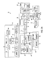
図1は、角膜、水晶体嚢、及び/又は水晶体核に正確な切開創を作るよう動作できる多くの実施形態としてのレーザ眼手術システム2を示している。システム2は、メインユニット4、患者チェア又は椅子6、デュアルファンクションフットスイッチ8、及びレーザフットスイッチ10を含む。
FIG. 1 shows a number of embodiments of a laser
メインユニット4は、システム2の多くの主要サブシステムを含む。例えば、外部から視認できるサブシステムは、タッチスクリーンディスプレイ制御パネル12、患者インターフェース組立体14、患者インターフェース真空接続部16、ドッキング制御キーパッド18、患者インターフェース無線認証(RFID)リーダ20、外部接続部22(例えば、ネットワーク、ビデオ出力、フットスイッチ、USBポート、ドアインターロック、及びAC電力)、レーザエミッション指示器24、非常時レーザ停止ボタン26、キースイッチ28、及び、USBデータポート30を含む。
The
患者チェア6は、ベース32、患者支持ベッド34、ヘッドレスト36、位置決め機構体、及び、ヘッドレスト36上に設けられた患者チェアジョイスティック制御部38、を含む。位置決め制御機構体は、ベース32と患者支持ベッド34とヘッドレスト36との間に結合されている。患者チェア6は、患者チェアジョイスティック制御部38を用いて3つの軸線(x,y,z)に調節され差し向けられるよう構成されている。ヘッドレスト36及び拘束システム(図示していないが、例えば、患者の額に係合する拘束ストラップ)は、手技中、患者の頭を安定化する。ヘッドレスト36は、患者に快適さをもたらすと共に患者の頭の動きを減少させる調節可能な頸部支持体を含む。ヘッドレスト36は、患者に快適さをもたらすと共に患者の頭のサイズのばらつきに対応するために、患者の頭の位置の調節を可能にするよう鉛直方向に調節可能であるように構成されている。
The
患者チェア6は、手動調節を用いて、患者の脚部、胴、及び頭の傾斜関節運動を許容する。患者チェア6は、患者負荷位置、吸引リング捕捉位置、及び患者治療位置に対応している。患者負荷位置では、チェア6は、患者チェアが直立位置に戻った状態で且つ患者フットレストが下降位置にある状態で、メインユニット4の下から回転する。吸引リング捕捉位置では、チェアは、患者チェアがもたれ位置に戻った状態で且つ患者フットレストが持ち上げ位置にある状態で、メインユニット4の下から回転する。患者治療位置では、チェアは、患者チェアがもたれ位置に戻った状態で且つ患者フットレストが持ち上げ位置にある状態で、メインユニット4の下に回転する。
The
患者チェア6は、意図しないチェアの運動を生じさせないようにする「チェアイネーブル(chair enable)」特徴を備えている。患者チェアジョイスティック38は、2つのやり方のうちのいずれにおいても使用可能にすることができる。第1に、患者チェアジョイスティック38は、ジョイスティックの頂部上に配置された「チェアイネーブル」ボタンを有する。「チェアイネーブル」ボタンを連続的に押すことによって、ジョイスティック38による患者チェア6の位置の制御をイネーブルにすることができる。変形例として、デュアルファンクションフットスイッチ8の左側フットスイッチ40を連続的に押すと、ジョイスティック38による患者チェア6の位置の制御をイネーブルにすることができる。
The
多くの実施形態で、患者制御ジョイスティック38は、比例制御器である。例えば、ジョイスティックを僅かな量動かすことにより、チェアがゆっくりと動くようにすることができる。ジョイスティックを多くの量動かすと、チェアは、速く動くことができる。ジョイスティックをその最大移動限度に保持すると、チェアは、最大チェア速度で動くことができる。有効チェア速度は、患者が患者インターフェース組立体14に近づいているときに減少されることができる。
In many embodiments, the
非常時停止ボタン26を押すと、全てのレーザ出力のエミッションを停止させ、患者をシステム2に結合している真空を解除し、そして患者チェア6をディスエーブルにすることができる。停止ボタン26は、キースイッチ28に隣接した状態でシステムフロントパネル上に設けられている。
Pressing the emergency stop button 26 stops all laser power emissions, releases the vacuum coupling the patient to the
キースイッチ28を用いると、システム2をイネーブルにすることができる。待機位置にあるとき、キーを取り外すことができ、するとシステムがディスエーブルになる。動作可能位置にあるとき、キーは、システム2への電力をイネーブルにする。
Using the
デュアルファンクションフットスイッチ8は、左側フットスイッチ40及び右側フットスイッチ42を含むデュアルフットスイッチ組立体である。左側フットスイッチ40は、「チェアイネーブル」フットスイッチである。右側フットスイッチ42は、「真空ON」フットスイッチであり、このフットスイッチは、液体光学系インターフェース吸引リングを患者の眼に固定するよう真空をイネーブルにする。レーザフットスイッチ10は、システムがイネーブルにある状態で押されたときに治療レーザを作動させるシュラウド付きフットスイッチである。
The dual
多くの実施形態で、システム2は、外部通信接続部を含む。例えば、システム2は、当該システム2をネットワークに接続するネットワーク接続部(例えば、RJ45ネットワーク接続部)を含むのが良い。ネットワーク接続部を用いると、治療報告のネットワーク印刷、システム性能ログを見るためのリモートアクセス、及びシステム診断を実施するためのリモートアクセス、をイネーブルにすることができる。システム2は、当該システム2により実施される治療のビデオを出力するために用いることができるビデオ出力ポート(例えばHDMI)を含むのが良い。出力ビデオは、例えば家族が見るため且つ/或いは訓練のため、外部モニタ上に表示するのが良い。出力ビデオは又、例えば永久記録保存目的で記録されるのが良い。システム2は、例えばデータ記憶装置への治療報告のエクスポートをイネーブルにするよう、1つ又は2つ以上のデータ出力ポート(例えば、USB)を含むのが良い。データ記憶装置上に記憶された治療報告は、任意適当な目的で、例えば、ユーザがネットワークを利用した印刷へのアクセス手段を持たない場合に外部コンピュータからの印刷のために、後でアクセスすることができる。
In many embodiments, the
図2は、患者眼43に結合されたシステム2の単純化されたブロック図である。患者眼43は、角膜43C、水晶体43L及び虹彩43Iを有する。虹彩43Iは、眼43とシステム2とのアラインメントを得るために使用できる眼43の瞳孔を定める。システム2は、切断レーザサブシステム44、レンジング(測距)サブシステム46、アラインメント誘導システム48、共用光学系50、患者インターフェース52、制御エレクトロニクス54、制御パネル/GUI56、ユーザインターフェース装置58、及び、通信経路60を含む。制御エレクトロニクス54は、通信経路60を介して、切断レーザサブシステム44、レンジングサブシステム46、アラインメント誘導サブシステム48、共用光学系50、患者インターフェース52、制御パネル/GUI56、及びユーザインターフェース装置58に作動的に結合されている。
FIG. 2 is a simplified block diagram of
多くの実施形態で、切断レーザサブシステム44は、フェムト秒(FS)レーザ技術を利用している。フェムト秒レーザ技術を用いることによって、短い持続時間(例えば、持続時間が約10-13秒)レーザパルス(エネルギーレベルがマイクロジュール範囲にある)を厳密に合焦された箇所に送り出して組織を破壊することができ、それにより、水晶体核の超音波断片化に必要なレベルと比較して且つ長い持続時間を有するレーザパルスと比較して、必要なエネルギーレベルを実質的に減少させることができる。
In many embodiments, the cutting
切断レーザサブシステム44は、システム2の構成に適した波長を有するレーザパルスを生じさせることができる。非限定的な例を挙げると、システム2は、1020nm〜1050nmの波長を有するレーザパルスを提供する切断レーザサブシステム44を使用するよう構成されているのが良い。例えば、切断レーザサブシステム44は、1030(±5)nm中心波長をもつダイオード励起固体形態を有するのが良い。
The cutting
切断レーザサブシステム44は、制御及び状態調節コンポーネントを含むのが良い。例えば、かかる制御コンポーネントは、例えばレーザパルスのエネルギー及びパルス列の平均電力を制御するためのビーム減衰器、レーザパルスを含むビームの断面空間広がりを制御するための固定アパーチュア、ビーム列のフラックス及び繰り返し率及びかくしてレーザパルスのエネルギーをモニタするための1つ又は2つ以上の電力モニタ、及びレーザパルスの伝送を可能にしたり遮断したりするためのシャッタ、のようなコンポーネントを含むのが良い。かかる状態調節コンポーネントは、レーザパルスを含むビームをシステム2の特性に適合させる調節可能なズーム組立体、及び、レーザパルスビームの位置及び/又は方向に関する変動性を許容してそれによりコンポーネントのばらつきのための裕度(tolerance)を増大させながらレーザパルスを或る距離にわたって伝えるための固定光学リレー、を含むのが良い。
The cutting
レンジングサブシステム46は、眼構造の空間配置状態を3つの寸法方向で測定するよう構成されている。測定される眼構造としては、角膜の前面及び後面や、水晶体嚢、虹彩及び角膜縁の前方部分及び後方部分、が挙げられる。多くの実施形態で、レンジングサブシステム46は、光干渉トモグラフィー(OCT)画像化を利用している。非限定的な例を挙げると、システム2は、780nm〜970nmの波長を用いたOCT画像化システムを使用するよう構成されるのが良い。例えば、レンジングサブシステム46は、810nm〜850nmの波長の広域スペクトルを採用したOCT画像化システムを含むのが良い。かかるOCT画像化システムは、眼内におけるOCT測定の有効深さを調節し、それにより深さが角膜の前面から水晶体嚢の後方部分までの範囲そしてこれを超える範囲にわたる眼の角膜及び眼の構造、の前方に位置する患者インターフェースの特徴を含むシステムコンポーネントの測定を可能にする、というように調節可能な基準経路長を採用するのが良い。
The ranging subsystem 46 is configured to measure the spatial arrangement of the eye structure in three dimensional directions. Eye structures measured include the anterior and posterior surfaces of the cornea and the anterior and posterior portions of the lens capsule, iris and corneal margin. In many embodiments, the ranging subsystem 46 utilizes optical interference tomography (OCT) imaging. As a non-limiting example,
アラインメント誘導サブシステム48は、システム2の光学コンポーネントを整列させるために用いられるレーザビームを生じさせるレーザダイオード又はガスレーザを含むのが良い。アラインメント誘導サブシステム48は、ドッキング及び治療中、患者の眼を位置合わせすると共に安定化するのを助けるための固視光を生じさせるLED又はレーザを含むのが良い。アラインメント誘導サブシステム48は、レーザ又はLED光源、及び、ビームをX,Y,及びZ方向に位置決めするために用いられるアクチュエータのアラインメント及び安定性をモニタするための検出器、を含むのが良い。アラインメント誘導サブシステム48は、患者の眼の画像化を可能にして患者インターフェース52への患者の眼43のドッキングを容易にするために使用できるビデオシステムを含むのが良い。ビデオシステムにより提供される画像化システムは又、GUIを介して切れ目の所在位置を方向付けるために使用できる。ビデオシステムにより提供される画像化は、更に、手技の進捗状況をモニタし、手技中における患者の眼43の運動(眼球運動)を追跡し、眼の構造、例えば瞳孔及び/又は角膜縁、の所在位置及びサイズを測定するために、レーザ眼手術手技中に使用可能である。
Alignment guidance subsystem 48 may include a laser diode or gas laser that produces a laser beam that is used to align the optical components of
共用光学系50は、患者インターフェース52と、切断レーザサブシステム44、レンジングサブシステム46、及びアラインメント誘導サブシステム48の各々と、の間に設けられた共通伝搬経路を提供する。多くの実施形態で、共用光学系50は、それぞれのサブシステム(例えば、切断レーザサブシステム44及びアラインメント誘導サブシステム48)からの放出光を受け取って放出光の向きを共通伝搬経路に沿って患者インターフェースに向けるためのビームコンバイナを含む。多くの実施形態で、共用光学系50は、各レーザパルスを焦点に集束させ又は合焦させる対物レンズ組立体を含む。多くの実施形態で、共用光学系50は、それぞれの放出光を3つの寸法方向に走査するよう動作可能な走査機構体を含む。例えば、共用光学系は、XY‐走査機構体及びZ‐走査機構体を含むのが良い。XY‐走査機構体を用いると、それぞれの放出光を、当該それぞれの放出光の伝搬方向を横切る2つの寸法方向に走査することができる。Z‐走査機構体を用いると、眼43内の焦点の深さを変化させることができる。多くの実施形態で、走査機構体は、レーザダイオードと対物レンズとの間に設けられ、その結果、走査機構体は、レーザダイオードによって生じたアラインメントレーザビームを走査するために用いられるようになっている。これとは対照的に、多くの実施形態で、ビデオシステムは、走査機構体がビデオシステムにより得られた像に影響を及ぼすことがないよう走査機構体と対物レンズとの間に配置されている。
Shared
患者インターフェース52は、患者の眼43の位置をシステム2に対して拘束するために用いられる。多くの実施形態で、患者インターフェース52は、真空の作用で患者の眼43に取り付けられる吸引リングを採用している。吸引リングは、例えば真空を用いて当該吸引リングを患者インターフェース52に固定することで、患者インターフェース52に結合される。多くの実施形態で、患者インターフェース52は、患者の角膜の前面から鉛直に位置がずらされた後面を有する光学的に透過性の構造を含み、適当な液体(例えば、滅菌緩衝生理的食塩水(BSS)、例えばAlcon BSS(アルコン(Alcon )部品番号(351‐55005‐1)又は均等物)の領域が患者インターフェースレンズ後面及び患者の角膜に接触した状態でこれらの間に配置されており、かかる適当な液体領域は、共用光学系50と患者の眼43との間の伝送経路の一部をなしている。光学的に透過性の構造は、1つ又は2つ以上の湾曲した表面を有するレンズ96を含むのが良い。変形例として、患者インターフェース52は、1つ又は2つ以上の実質的に平坦な表面、例えば平行なプレート又はウェッジ、を有する光学的に透過性の構造を含んでも良い。多くの実施形態で、患者のインターフェースレンズは、使い捨てであり、これを任意適当な間隔で、例えば各眼治療前に、交換するのが良い。
The
制御エレクトロニクス54は、切断レーザサブシステム44、レンジングサブシステム46、アラインメント誘導サブシステム48、患者インターフェース52、制御パネル/GUI56及びユーザインターフェース装置58の動作を制御すると共に通信経路60を介してこれらからの入力を受け取ることができる。通信経路60は、任意適当な形態で具体化でき、かかる形態としては、制御エレクトロニクス54とそれぞれのシステムコンポーネントとの間の任意適当な共用又は専用の通信経路が挙げられる。制御エレクトロニクス54は、任意適当なコンポーネント、例えば1つ又は2つ以上のプロセッサ、1つ又は2つ以上の書き換え可能ゲートアレイ(FPGA)、及び1つ又は2つ以上のメモリ記憶装置、を含むのが良い。多くの実施形態で、制御エレクトロニクス54は、ユーザ指定の治療パラメータに従って術前計画を提供すると共にレーザ眼手術手技に対するユーザ管理を提供するよう、制御パネル/GUI56を制御する。
The
ユーザインターフェース装置58は、ユーザ入力を制御エレクトロニクス54に提供するのに適した任意適当なユーザ入力装置を含むことができる。例えば、ユーザインターフェース装置58は、例えばデュアルファンクションフットスイッチ8、レーザフットスイッチ10、ドッキング制御キーパッド18、患者インターフェース無線認証(RFID)リーダ20、非常時レーザ停止ボタン26、キースイッチ28、及び患者チェアジョイスティック制御部38、のような装置を含むのが良い。
User interface device 58 may include any suitable user input device suitable for providing user input to control
図3Aは、システム2に含めることができる多くの実施形態としての組立体62を示す単純化されたブロック図である。組立体62は、切断レーザサブシステム44、レンジングサブシステム46、アラインメント誘導サブシステム48、共用光学系50、及び患者インターフェース52の好適な形態の非限定的な実施例であると共にこれらの統合例である。切断レーザサブシステム44、レンジングサブシステム46、アラインメント誘導サブシステム48、共用光学系50、及び患者インターフェース52の他の形態及び統合例が可能であり、これらは、当業者には明らかである。
FIG. 3A is a simplified block diagram illustrating an exemplary assembly 62 that can be included in the
組立体62は、光学ビームを患者の眼43中に投射して走査するよう動作可能である。切断レーザサブシステム44は、超高速(UF)レーザ64(例えば、フェムト秒レーザ)を含む。組立体62を用いて、患者の眼43内で、3つの寸法方向X、Y、及びZにおいて光学ビームを走査するのが良い。例えば、UFレーザ64によって生じる短パルスレーザ光を眼組織中に合焦させて誘電破壊を生じさせ、それにより光切断を焦点(焦点ゾーン)周りに生じさせるのが良く、それにより、光誘起プラズマの付近の組織が断裂する。組立体62では、レーザ光の波長は、800nmから1200nmまで様々であって良く、レーザ光のパルス幅は、10fsから10000fsまで様々であって良い。パルス繰り返し周波数も又、10kHzから500kHzまで様々であって良い。非標的組織に対する意図しない損傷に関する安全限度は、繰り返し率及びパルスエネルギーに関して上限を定める。しきい値エネルギー、手技を終了させるまでの時間、及び安定性は、パルスエネルギー及び繰り返し率に関して下限を定める場合がある。眼43内、具体的には眼の水晶体及び水晶体嚢内の、合焦スポットのピーク電力は、光学破壊を生じさせると共にプラズマ媒介アブレーションプロセスを開始させるのに十分である。レーザ光については近赤外波長が好ましく、その理由は、生物学的組織中の線形光吸収及び散乱が近赤外波長について減少するからである。一例として、レーザ64は、120kHz(±5%)の繰り返し率及び1〜20マイクロジュール範囲の個々のパルスエネルギーで600fs未満の持続時間を有するパルスを生じさせる、繰り返しパルス化1031nm装置であるのが良い。
The assembly 62 is operable to project and scan the optical beam into the patient's
切断レーザサブシステム44は、制御エレクトロニクス54及びユーザにより、制御パネル/GUI56及びユーザインターフェース装置58を介して制御され、それによりレーザパルスビーム66が生じる。制御パネル/GUI56は、システム動作パラメータを設定し、ユーザ入力を処理し、集められた情報、例えば眼組織の像、を表示すると共に患者の眼43内に形成されるべき切開創の描写を表示するために用いられる。
The cutting
生じたレーザパルスビーム66は、ズーム組立体68を通って進む。レーザパルスビーム66は、ユニットごとに、特にUFレーザ64が異なるレーザ製造業者から得られる場合、様々であって良い。例えば、レーザパルスビーム66のビーム直径は、ユニットごとに様々であって良い(例えば、±20%だけ)。ビームは又、ビーム品質、ビーム発散度、ビーム空間真円度、及び収差に関して、様々であって良い。多くの実施形態で、ズーム組立体68は、当該ズーム組立体68から出たレーザパルスビーム66がユニットごとに一貫したビーム直径及び発散度を有する、というように調整可能である。 The resulting laser pulse beam 66 travels through the zoom assembly 68. The laser pulse beam 66 may vary from unit to unit, especially if the UF laser 64 is obtained from a different laser manufacturer. For example, the beam diameter of the laser pulse beam 66 may vary from unit to unit (eg, only ± 20%). The beam can also vary in terms of beam quality, beam divergence, beam space roundness, and aberrations. In many embodiments, the zoom assembly 68 is adjustable such that the laser pulse beam 66 exiting the zoom assembly 68 has a consistent beam diameter and divergence from unit to unit.
ズーム組立体68を出た後、レーザパルスビーム66は、減衰器70を通って進む。減衰器70は、レーザビームの透過率及びかくしてレーザパルスビーム66中のレーザパルスのエネルギーレベルを調整するために用いられる。減衰器70は、制御エレクトロニクス54を介して制御される。
After exiting the zoom assembly 68, the laser pulse beam 66 travels through the
減衰器70を出た後、レーザパルスビーム66は、アパーチュア72を通って進む。アパーチュア72は、レーザパルスビーム66の外側の有効直径を設定する。次に、ズームは、アパーチュア存在場所のところでのビームのサイズ及びかくして透過される光の量を定める。透過光の量は、高と低の両方が定められる。上限は、眼内で達成できる最も高い開口数(NA)を達成するための要件によって定められる。高NAは、非標的組織についての低いしきい値エネルギー及び大きな安全マージンを促進する。下限は、高い光学スループットに関する要件によって定められる。システム内の透過損失が多すぎると、これによりシステムの寿命が短くなる。というのは、レーザ出力及びシステムが経時的に劣化するからである。加うるに、このアパーチュアを通る透過量が一貫していることが、各手技に関する最適セッティングの決定(及び共用)における安定性を促進する。典型的には、最適性能を達成するためには、このアパーチュアを通る透過量は、88%〜92%に設定される。
After exiting the
アパーチュア72を出た後、レーザパルスビーム66は、2つの出力ピックオフ74を通って進む。各出力ピックオフ74は、各レーザパルスの一部分をそれぞれの出力モニタ76にそらすための部分反射ミラーを含むのが良い。2つの出力ピックオフ74(例えば、主要及び補助)及びそれぞれの主要及び補助出力モニタ76は、主要出力モニタ76の誤動作の場合に冗長性を提供するために用いられる。
After exiting
出力ピックオフ74を出た後、レーザパルスビーム66は、システム制御シャッタ78を通って進む。システム制御シャッタ78は、手技上及び安全上の理由でレーザパルスビーム66のオン/オフ制御を保証する。2つの出力ピックオフは、シャッタに先行して、ビームパワー、エネルギー及び繰り返し率のモニタリングをシャッタの開放のための前提条件として考慮する。
After exiting
システム制御シャッタ78を出た後、光ビームは、光学系リレーテレスコープ80を通って進む。光学系リレーテレスコープ80は、レーザパルスビーム66を或る距離にわたって伝搬させる一方でレーザパルスビーム66の位置的及び方向的変動性を許容し、それによりコンポーネントのばらつきに関する裕度を増大させる。一例として、光学リレーは、アパーチュア位置の像をxyガルボミラー位置の近くの共役位置に中継するケプラー型無焦点(アフォーカル)望遠鏡であるのが良い。この態様では、XYガルボ配置場所のところでのビームの位置は、アパーチュア位置のところでのビーム角度の変化に対して不変(無関係)である。同様に、シャッタは、リレーに先立つ必要はなく、リレーの後に続いても良く又はリレー内に含まれても良い。 After exiting the system control shutter 78, the light beam travels through the optical relay telescope 80. The optical relay telescope 80 allows the positional and directional variability of the laser pulse beam 66 while propagating the laser pulse beam 66 over a distance, thereby increasing the tolerance for component variations. As an example, the optical relay may be a Kepler type afocal telescope that relays an image of the aperture position to a conjugate position near the xy galvo mirror position. In this aspect, the position of the beam at the XY galvo placement location is invariant (irrelevant) to changes in the beam angle at the aperture location. Similarly, the shutter need not precede the relay and may follow the relay or be included within the relay.
光学系リレーテレスコープ80を出た後、レーザパルスビーム66は、共用光学系50に送られ、共用光学系50は、レーザパルスビーム66を患者インターフェース52まで伝搬させる。レーザパルスビーム66は、ビームコンバイナ82に入射し、ビームコンバイナ82は、レーザパルスビーム66を反射する一方でレンジングサブシステム46及びアラインメント誘導サブシステム(AIM)48からの光ビームを透過させる。
After exiting the optical relay telescope 80, the laser pulse beam 66 is sent to the shared
ビームコンバイナ82の次に、レーザパルスビーム66は、Z‐テレスコープ84を通って進み続ける。Z‐テレスコープ84は、Z軸に沿って患者の眼43内でレーザパルス66の合焦位置を走査するよう動作可能である。例えば、Z‐テレスコープ84は、2つのレンズ群(各レンズ群は、1つ又は2つ以上のレンズを含む)を有するガリレイ望遠鏡を含むのが良い。レンズ群のうちの一方は、Z‐テレスコープ84のコリメーション位置周りでZ軸に沿って動く。この態様では、患者の眼43内のスポットの焦点位置は、Z軸に沿って動く。一般に、レンズ群の動きと焦点の動きとの間には或る関係が存在する。例えば、Z‐テレスコープは、約2倍のビーム拡大比と、レンズ群の動きと焦点の動きとの間の1:1に近い関係と、を有するのが良い。眼座標系のZ軸におけるレンズの動きと焦点の動きとの間に成り立つ正確な関係は、一定の線形(比例)関係である必要はない。この動きは、非線形であっても良く、モデル又は測定からの較正を介して、或いは、これら両方の組み合わせを介して、定められても良い。変形例として、焦点の位置をZ軸に沿って調節するために他方のレンズ群をZ軸に沿って動かしても良い。Z‐テレスコープ84は、患者の眼43内でレーザパルスビーム66の焦点を走査するためのZ‐走査装置として機能する。Z‐テレスコープ84は、制御エレクトロニクス54によって自動的に且つ動的に制御されるのが良く、そして次に説明するX及びY走査装置とは別個独立であり又はこれと相互作用するよう選択可能である。
Following the
Z‐テレスコープ84を通過した後、レーザパルスビーム66は、X‐走査装置86に入射し、このX‐走査装置は、レーザパルスビーム66をX方向に走査するよう動作可能であり、X方向は、主としてZ軸を横切る方向であり且つレーザパルスビーム66の伝搬方向を横切る方向である。X‐走査装置86は、制御エレクトロニクス54によって制御され、このX‐走査装置は、適当なコンポーネント、例えば、モータ、ガルバノメータ(検流計)、又は任意の他の周知の光学可動装置、を含むのが良い。Xアクチュエータの動作の関数としてのビームの動きの関係は、一定又は線形である必要はない。この関係のモデル化若しくは較正測定又はこれら両方の組み合わせが決定され得て、これを用いてビームの所在位置を定める(方向付ける)ことができる。
After passing through the Z-telescope 84, the laser pulse beam 66 is incident on the X-scan device 86, which is operable to scan the laser pulse beam 66 in the X direction, and in the X direction. Is a direction that mainly crosses the Z-axis and a direction that crosses the propagation direction of the laser pulse beam 66. The X-scan device 86 is controlled by the
X‐走査装置86によって定められた後、レーザパルスビーム66は、Y‐走査装置88に入射し、このY‐走査装置は、レーザパルスビーム66をY方向に走査するよう動作可能であり、Y方向は、主としてX軸及びZ軸を横切る方向である。Y‐走査装置88は、制御エレクトロニクス54によって制御され、このY‐走査装置は、適当なコンポーネント、例えば、モータ、ガルバノメータ(検流計)、又は任意の他の周知の光学可動装置、を含むのが良い。Yアクチュエータの動作の関数としてのビームの動きの関係は、一定又は線形である必要はない。この関係のモデル化若しくは較正測定又はこれら両方の組み合わせが決定され得て、そしてこれを用いてビームの所在位置を定めることができる。変形例として、X‐走査装置86及びY‐走査装置88の機能は、Z軸及びレーザパルスビーム66の伝搬方向を横切る方向の2つの寸法方向にレーザパルスビーム66を走査するよう構成されたXY‐走査装置によって提供されても良い。X‐走査装置86及びY‐走査装置88は、レーザパルスビーム66の結果としての方向を変化させ、それにより患者の眼43内に位置するUF焦点の側方変位を生じさせる。
After being defined by the X-scan device 86, the laser pulse beam 66 is incident on the Y-scan device 88, which is operable to scan the laser pulse beam 66 in the Y direction, Y The direction is mainly a direction crossing the X axis and the Z axis. The Y-scan device 88 is controlled by the
Y‐走査装置88によって定められた後、レーザパルスビーム66は、ビームコンバイナ90を通過する。ビームコンバイナ90は、レーザパルスビーム66を透過させる一方で、光ビームをアラインメント誘導サブシステム48のビデオサブシステム92に反射したりこのビデオサブシステム92からの光ビームを反射したりするよう構成されている。
After being defined by Y-scan device 88, laser pulse beam 66 passes through
ビームコンバイナ90を通過した後、レーザパルスビーム66は、対物レンズ組立体94を通過する。対物レンズ組立体94は、1つ又は2つ以上のレンズを含むのが良い。多くの実施形態で、対物レンズ組立体94は、多数のレンズを含む。対物レンズ組立体94の複雑さは、走査フィールドサイズ、合焦スポットサイズ、テレセントリシティ度、対物レンズ組立体94の近位側及び遠位側の両方の有効作業距離、並びに、収差制御量によって、高められる場合がある。
After passing through the
対物レンズ組立体94を通過した後、レーザパルスビーム66は、患者インターフェース52を通過する。上述したように、多くの実施形態で、患者インターフェース52は、患者の角膜の前面から鉛直に位置がずらされた後面を有する患者インターフェースレンズ96を含み、適当な液体(例えば、滅菌緩衝生理的食塩水(BSS)、例えばAlcon BSS (アルコン(Alcon )部品番号(351‐55005‐1)又は均等物)の領域が患者インターフェースレンズ96の後面及び患者の角膜に接触した状態でこれらの間に配置されており、かかる適当な液体領域は、共用光学系50と患者の眼43との間の伝送経路の一部をなしている。
After passing through the objective lens assembly 94, the laser pulse beam 66 passes through the
制御エレクトロニクス54の制御下にある共用光学系50は、照準、レンジング、及び治療走査パターンを自動的に生成することができる。かかるパターンは、光の単一スポット、光の多数のスポット、光の連続パターン、光の多数の連続パターン、及び/又はこれらの任意の組み合わせ、で構成されるのが良い。加うるに、照準パターン(以下に説明する照準ビーム108を用いる)は、治療パターン(レーザパルスビーム66を用いる)と同一である必要はないが、オプションとして、レーザパルスビーム66が患者の安全のために所望の標的範囲内にのみ送り出されるという確認をもたらすべく治療パターンの限界を指示する、というように用いられるのが良い。これは、例えば、照準パターンが意図した治療パターンの輪郭を提供するようにさせることによって行われるのが良い。このように、治療パターンの空間広がりは、個々のスポット自体の正確な所在位置が分からない場合であってもユーザに知られるようにすることができ、かくして、走査は、速度、効率、及び/又は精度に関して最適化される。この照準パターンは又、ユーザに対するその視認性を更に高めるために、明滅として知覚されるよう形成できる。同様に、レンジングビーム102は、治療ビーム又はパターンと同一である必要はない。レンジングビームは、標的表面を識別(特定)するのに足るほど十分でありさえすれば良い。これら表面は、角膜及び水晶体の前面並びに後面を含むのが良く、これら表面は、単一の曲率半径を有する球とみなされ得る。また、光学系は、アラインメント誘導によって共用され、ビデオサブシステムは、治療ビームによって共用されるビデオサブシステムと同一である必要はない。レーザパルスビーム66の位置決め及び性質及び/又はレーザパルスビーム66が眼43上に形成する走査パターンは、更に、患者及び/又は光学システムを位置決めするための入力装置、例えばジョイスティック又は任意他の適当なユーザ入力装置(例えば、制御パネル/GUI56)、の使用によって制御できる。
The shared
制御エレクトロニクス54は、眼43内の標的構造を標的にすると共にレーザパルスビーム66が適当な場所に合焦されて意図しない状態で非標的組織を損傷させることがないことを保証するようにするように構成されるのが良い。本明細書において説明する画像化モダリティ及び技術、例えば上述の画像化モダリティ及び技術、又は超音波は、水晶体及び水晶体嚢の所在位置を突き止めると共にその厚さを測定するために用いられるのが良く、それによりレーザ合焦方法に高い精度をもたらすことができ、かかる方法としては、2Dパターニング及び3Dパターニングが挙げられる。レーザ合焦は又、1つ又は2つ以上の方法を用いることによって達成でき、かかる方法としては、照準ビームの直接観察、又は他の公知のオフサルミック又は医用画像化モダリティ、例えば上述の画像化モダリティ、及び/又はこれらの組み合わせが挙げられる。加うるに、レンジングサブシステム、例えばOCTは、患者インターフェースと関与する特徴又は観点を検出するために使用できる。特徴としては、ドッキング構造体及び使い捨てレンズの光学構造体上の基準場所、例えば、前面及び後面の所在位置が挙げられる。
The
図3の実施形態で、レンジングサブシステム46は、OCT画像化装置を含む。追加的に又は代替的に、OCT画像化以外の画像化モダリティを用いることができる。眼のOCT走査は、患者の眼43内の関心のある構造の空間配置状態(例えば、境界部上の箇所の3次元座標、例えばX、Y、及びZ)を測定するために使用できる。関心のあるかかる構造としては、例えば、角膜の前面、角膜の後面、水晶体嚢の前方部分、水晶体嚢の後方部分、水晶体の前面、水晶体の後面、虹彩、瞳孔、及び/又は角膜縁が挙げられる。制御エレクトロニクス54によって、関心のある構造及び/又は適当にマッチングする幾何学的モデル化、例えば表面及び曲線、の空間配置状態を生じさせることができ及び/或いは用いることができ、それにより次のレーザ補助手術手技をプログラムすると共に制御することができる。関心のある構造及び/又は適当にマッチングする幾何学的モデル化の空間配置状態は又、手技に関連付けられた多様なパラメータ、例えば、とりわけ、水晶体嚢を切断するために用いられる焦平面の軸方向上限及び軸方向下限、水晶体皮質及び核の断片化、及び水晶体嚢の厚さ、を求めるために使用できる。
In the embodiment of FIG. 3, the ranging subsystem 46 includes an OCT imaging device. Additionally or alternatively, imaging modalities other than OCT imaging can be used. The OCT scan of the eye can be used to measure the spatial arrangement of the structure of interest within the patient's eye 43 (eg, three-dimensional coordinates of locations on the boundary, eg, X, Y, and Z). Such structures of interest include, for example, the anterior surface of the cornea, the posterior surface of the cornea, the anterior portion of the capsular bag, the posterior portion of the capsular bag, the anterior surface of the lens, the posterior surface of the lens, the iris, the pupil, and / or the limbus. . The
図3のレンジングサブシステム46は、OCT光源及び検出装置98を含む。OCT光源及び検出装置98は、適当な広域スペクトルを持つ光を生成して放出する光源を含む。例えば、多くの実施形態で、OCT光源及び検出装置98は、810nm〜850nmの波長の広域スペクトルを持つ光を生成して放出する。生成されて放出された光は、シングルモード光ファイバ接続部によって装置98に結合される。 The ranging subsystem 46 of FIG. 3 includes an OCT light source and detector 98. The OCT light source and detector 98 includes a light source that generates and emits light having an appropriate broad spectrum. For example, in many embodiments, the OCT light source and detection device 98 generates and emits light having a broad spectrum with a wavelength of 810 nm to 850 nm. The generated and emitted light is coupled to device 98 by a single mode optical fiber connection.
OCT光源及び検出装置98から放出された光は、ビームコンバイナ100に通され、ビームコンバイナ100は、この光をサンプル部分102と基準部分104に分割する。サンプル部分102の大部分は、共用光学系50を通って透過される。サンプル部分の比較的僅かな部分が、患者インターフェース52及び/又は患者の眼43から反射されて共用光学系50を通って戻り、ビームコンバイナ100を通って戻り、そしてOCT光源及び検出装置98に入る。基準部分104は、調整可能な経路長を有する基準経路106に沿って伝えられる。基準経路106は、ビームコンバイナ100からの基準部分104を受け取り、この基準部分104を調節可能な経路長にわたって伝搬させ、そして基準部分104をビームコンバイナ100に戻すよう構成されており、ビームコンバイナ100は、次に、戻された基準部分104をOCT光源及び検出装置98に向けて戻す。次に、OCT光源及び検出装置98は、サンプル部分102の戻っている僅かな部分及び戻っている基準部分104を検出組立体中に差し向ける。検出組立体は、時間領域検出技術、周波数検出技術、又は単一点検出技術を採用する。例えば、周波数領域技術は、波長が830nmであり且つ帯域幅が10nmのOCTで用いることができる。
The light emitted from the OCT light source and detection device 98 is passed through the
ビームコンバイナ82の次にUFレーザパルスビーム66といったん組み合わされると、OCTサンプル部分ビーム102は、共用光学系50及び患者インターフェース52を通る当該UFレーザパルスビーム66と一緒に共用経路を辿る。このように、OCTサンプル部分ビーム102は、一般に、UFレーザパルスビーム66の所在位置を表している。UFレーザビームと同様、OCTサンプル部分ビーム102は、Z‐テレスコープ84を通過し、そしてX‐走査装置86及びY‐走査装置88によって変向され、対物レンズ組立体94及び患者インターフェース52を通り、そして眼43内に入る。眼内における構造の反射及び散乱により、戻りビームが生じ、かかる戻りビームは、患者インターフェース52を通って戻り、共用光学系50を通って戻り、ビームコンバイナ100を通って戻り、そしてOCT光源及び検出装置98中に戻る。サンプル部分102の戻り反射光は、戻り基準部分104と組み合わされてOCT光源及び検出装置98の検出器部分中に差し向けられ、かかる検出器部分は、組み合わされた戻りビームに応じてOCT信号を生じさせる。生じたOCT信号は、制御エレクトロニクスによって解釈され、それにより患者の眼43内の関心のある構造の空間配置状態が判定される。生じたOCT信号は又、患者インターフェース52の位置及び向きを測定すると共に患者インターフェースレンズ96の後面と患者の眼43との間に液体が存在しているか否かを判定するために、制御エレクトロニクスによって解釈されるのが良い。
Once combined with the UF laser pulse beam 66 following the
OCT光源及び検出装置98は、基準経路106とサンプル経路との間の光路長の差を測定する原理で働く。したがって、UFレーザビームの焦点を変更するためのZ‐テレスコープ84の異なるセッティングは、眼内における患者インターフェース体積部の軸方向静止表面のためのサンプル経路の長さに影響を及ぼさない。というのは、この光路長は、Z‐テレスコープ84の異なるセッティングの関数として変化しないからである。レンジングサブシステム46は、光源及び検出方式に関連付けられた固有のZ範囲を有し、周波数領域検出方式の場合、Z範囲は、具体的には、分光計、波長、帯域幅、及び基準経路106の長さに関連付けられる。図3で用いられているレンジングサブシステム46の場合、Z範囲は、水性環境内において約4〜5mmである。この範囲を少なくとも20〜25mmに広げるには、レンジングサブシステム46内のステージZEDを介しての基準経路106の経路長の調節が必要である。サンプル経路長に影響を及ぼさないでOCTサンプル部分ビーム102をZ‐テレスコープ84中に通すことにより、OCT信号強度の最適化が考慮される。これは、OCTサンプル部分ビーム102を標的構造上に合焦させることによって達成される。合焦ビームは、シングルモード光ファイバを通って伝送可能な戻り反射ないし散乱信号を増大させると共に、当該合焦ビームの広がりの減少に起因して空間分解能を高める。サンプルOCTビームの焦点の変更は、基準経路106の経路長の変更とは無関係に達成できる。
The OCT light source and detector 98 works on the principle of measuring the optical path length difference between the
サンプル部分102(例えば、810nm〜850nmの波長)及びUFレーザパルスビーム66(例えば、1020nm〜1050nm波長)が共用光学系50及び患者インターフェース52を通ってどのように伝搬するかにおける、例えば浸漬インデックス、屈折、収差(有色と単色の両方)のような影響に起因する基本的な差のために、OCT信号をUFレーザパルスビーム66の焦点場所に対して分析する際に注意が払われなければならない。OCT信号情報をUFレーザパルスビーム焦点場所に、そして更に相対的ないし絶対的な寸法上の量にマッチングさせるべく、X、Y、及びZの関数としての較正又は登録手順が実施され得る。
For example, the immersion index in how the sample portion 102 (eg, 810 nm to 850 nm wavelength) and the UF laser pulse beam 66 (eg, 1020 nm to 1050 nm wavelength) propagates through the shared
OCT干渉計の構成については、多くの好適な可能性が存在する。例えば、別の好適な構成としては、時間及び周波数領域方式、シングル及びデュアルビーム方法、被掃引源等が、米国特許第5,748,898号明細書、同第5,748,352号明細書、同第5,459,570号明細書、同第6,111,645号明細書、及び同第6,053,613号明細書に記載されている。 There are many suitable possibilities for the configuration of the OCT interferometer. For example, other suitable configurations include time and frequency domain systems, single and dual beam methods, swept sources, etc., US Pat. Nos. 5,748,898, 5,748,352. No. 5,459,570, No. 6,111,645, and No. 6,053,613.
システム2は、水晶体嚢及び角膜の前面及び後面の存在場所を突き止めてUFレーザパルスビーム66が所望の開口部のあらゆる箇所のところで水晶体嚢及び角膜上に合焦されることを保証するよう、設定されるのが良い。本明細書において説明する画像化モダリティ及び技術、例えば光干渉トモグラフィー(OCT)及び例えばプルキンエ画像化、シャインプルーク画像化、共焦点又は非線形光学顕微鏡、蛍光画像化、超音波、構造化光、立体画像化、又は他の公知のオフサルミック又は医用画像化モダリティ及び/又はこれらの組み合わせを用いると、水晶体、水晶体嚢及び角膜の、形状、幾何学的形状、周長、境界、及び/又は3次元存在場所を求めることができ、それにより2D及び3Dパターニングを含むレーザ合焦方法により高い精度を与えられる。レーザ合焦部は又、1つ又は2つ以上の方法を用いて達成でき、かかる方法としては、照準ビームの直接観察又は他の公知のオフサルミック又は医用画像化モダリティ及びこれらの組み合わせ、例えば上述したモダリティ及び組み合わせ(これらには限定されない)、が挙げられる。
角膜、前眼房及び水晶体の光学画像化は、切断のためのパターンを作るために用いられるのと同一のレーザ及び/又は同一のスキャナを用いて達成できる。光学画像化を用いると、前及び後水晶体嚢の軸方向存在場所及び形状(及び厚さ)、白内障の水晶体核の境界、並びに、前眼房及び角膜の特徴の深さ、に関する情報を提供することができる。次に、この情報をレーザ3D走査システムにロードすることができ、又は、これを用いて眼の角膜、前眼房、及び水晶体の3次元モデル/表示/画像を生成することができると共に、かかる情報を用いると、手術手技で用いられる切断パターンを定めることができる。 Optical imaging of the cornea, anterior chamber and lens can be accomplished using the same laser and / or the same scanner that is used to create the pattern for cutting. Optical imaging provides information about the axial location and shape (and thickness) of the anterior and posterior lens capsule, the boundary of the cataractous lens nucleus, and the depth of anterior chamber and corneal features be able to. This information can then be loaded into a laser 3D scanning system or can be used to generate a 3D model / display / image of the cornea, anterior chamber, and lens of the eye, and so on Using the information, the cutting pattern used in the surgical procedure can be defined.
照準ビームの観察は又、UFレーザパルスビーム66の焦点を位置決めするのを助けるために使用できる。加うるに、赤外OCTサンプル部分ビーム102及びUFレーザパルスビーム66に代わる裸眼で見える照準ビームは、当該照準ビームが赤外ビームパラメータを正確に表示していることを条件として、アラインメントに役立ちうる。アラインメント誘導サブシステム48は、図3に示されている組立体62に含まれる。照準ビーム108は、照準ビーム光源110、例えば630〜650nm範囲のレーザダイオード、により生じる。
The aiming beam observation can also be used to help position the focus of the UF laser pulse beam 66. In addition, the aiming beam visible to the naked eye instead of the infrared OCT sample
照準ビーム光源110が照準ビーム108を生じさせると、照準ビーム108は、照準経路112に沿って共用光学系50に伝えられ、ここで、当該照準ビームの向きがビームコンバイナ114によって変えられる。ビームコンバイナ114によって偏向された後、照準ビーム108は、共用光学系50及び患者インターフェース52を通るUFレーザパルスビーム66と一緒に共用経路を辿る。このように、照準ビーム108は、UFレーザパルスビーム66の存在場所を表す。照準ビーム108は、Z‐テレスコープ84を通り、X‐走査装置86及びY‐走査装置88によって偏向され、ビームコンバイナ90を通り、対物レンズ組立体94及び患者インターフェース52を通り、そして患者の眼43中に入る。
When the aiming beam source 110 generates the aiming
ビデオサブシステム92は、患者インターフェース及び患者の眼の像を得るよう動作可能である。ビデオサブシステム92は、カメラ116、照明光源118、及びビームコンバイナ120を含む。ビデオサブシステム92は、既定の構造周り又はその内部におけるパターン心合わせを提供するために制御エレクトロニクス54によって使用できる像を集める。照明光源118は、一般に、広帯域且つ非干渉性であるのが良い。例えば、光源118は、多数のLEDを含むのが良い。照明光源118の波長は、好ましくは、700nm〜750nmであるが、照明光源118からの光をUFレーザパルスビーム66、OCTサンプルビーム102、及び照準ビーム108のためのビーム経路と組み合わせるビームコンバイナ90によって許容される波長範囲であればどのような波長範囲であっても良い(ビームコンバイナ90は、当該ビデオ波長を反射する一方でOCT及びUF波長を透過させる)。ビームコンバイナ90は、照準ビーム108の波長を部分的に透過させることができ、その結果、照準ビーム108は、カメラ116で見えるようになる。オプションとしての偏光素子が照明光源118の前に配置されるのが良く、かかるオプションとしての偏光素子は、信号を最適化するために用いられる。オプションとしての偏光素子は、例えば、直線偏光子、四分の一波長板、半波長板又は任意の組み合わせであるのが良い。追加のオプションとしての検光子がカメラの前に配置されるのが良い。偏光子と検光子の組み合わせは、交差直線偏光子であるのが良く、それにより、望まれていない表面、例えば対物レンズ表面、からのスペクトル反射光がなくなる一方で、標的表面、例えば眼の意図した構造、からの散乱光の通過が可能である。照明は又、照明源がビデオシステムの画像化部分の捕捉開口数の外部に位置する独立した表面に差し向けられるよう、暗視野形態内に位置するのが良い。変形例として、照明は又、明視野形態内に位置しても良い。暗視野形態と明視野形態との両方において、照明光源は、患者のための固定ビームとして使用されるのが良い。照明は又、患者の瞳孔を照明して瞳孔と虹彩との境界を強調して虹彩検出及び眼追跡を容易にするために使用できる。近赤外波長又はその帯域幅によって生じる疑似色画像は、許容可能であると言える。
照明光源118からの照明光は、ビームコンバイナ120を通ってビームコンバイナ90に送られる。ビームコンバイナ90から、照明光は、対物レンズ組立体94及び患者インターフェース52を通って患者の眼43の方へ差し向けられる。眼43の種々の構造及び患者インターフェースから反射されて散乱された照明光は、患者インターフェース52を通って戻り、対物レンズ組立体94を通って戻り、そしてビームコンバイナ90に戻る。ビームコンバイナ90のところで、戻っている光は、ビームコンバイナ120に差し向けられて戻され、ここで、戻っている光の向きは、カメラ116の方へ変えられる。ビームコンバイナは、立方体であっても良く、板状であっても良く、又は薄膜状の要素であって良い。ビームコンバイナは又、スパイダーミラーの形態をしていても良く、それにより、照明光は、ミラーの外部広がりを超えて伝わり、一方で、像経路は、ミラーの内側反射面で反射する。変形例として、ビームコンバイナは、スクレーパミラーの形態をしていても良く、この場合、照明光は、穴を通って伝えられ、これに対し、像経路は、穴の外側に位置するミラーの反射面で反射する。カメラ116は、適当な画像化装置であって良く、例えば、適当なサイズのフォーマットのシリコンを利用した検出器アレイ(これには限定されない)であって良い。ビデオレンズは、カメラの検出器アレイ上に像を結び、他方、光学素子は、それぞれ偏光制御及び波長フィルタリングを可能にする。アパーチュア又は虹彩は、画像化NAの制御及びかくして焦点深度並びに被写界深度及び分解能を制御する。小さなアパーチュアは、患者ドッキング手順を助ける大きな被写界深度という利点を提供する。変形例として、照明経路とカメラ経路を切り替えることができる。さらに、照準光源110は、直接的には目に見えないが、ビデオサブシステム92を用いて捕捉されて表示できる赤外光を放出するよう構成され得る。
The illumination light from the
図3Bは、眼のマッピングされた治療領域を示しており、当該治療領域は、角膜、後水晶体嚢、及び角膜縁を含む。当該治療領域は、例えばレーザビーム品質、パルス幅、システム透過率、開口数、偏光、収差補正、及びアラインメントのような要因を組み込むために、コンピュータモデル化、例えば光線追跡及びフェーズド利用光学モデル化、によりマッピングされるのが良い。治療体積部は、患者インターフェースの光学的に透過性の構造体の前面からZ軸に沿って15mmを超える距離にわたって延びているものとして示されており、治療体積部は、角膜及び水晶体を含み、当該水晶体の治療体積部は、前水晶体嚢、後水晶体嚢、水晶体核及び皮質を含む。治療体積部は、角膜の中心から角膜縁を超えるところまで側方に延びている。体積部の側方寸法は、角膜縁の前方に位置するY輪郭及び角膜縁の後方に位置するX輪郭によって定められる。図示の治療体積部は、本明細書において説明する教示に基づいて当業者によって決定可能である。30mmに固定されたZL及び20mmに固定されたZLについての予想光学破壊の側方位置が示されている。Z方向寸法に沿う軸線99に対して横方向に延びるこれら表面は、軸線99から離れた側方の場所のところで光学破壊をもたらすようXガルボ及びYガルボの光学走査の場所に対応している。ZL‐30mm及びZL‐20mmについて光学破壊の走査経路の湾曲した非平面状の形状は、本明細書において説明するマッピング及びルックアップテーブルにより補正することができる。焦点の湾曲形状を光学破壊深度のワーピング(狂い)と呼ぶ場合があり、ルックアップテーブルは、例えば治療深度のワーピングを補償するよう、逆にワーピングされるが、又は違ったやり方で調節されるのが良い。加うるに、モデルからの予想に特有のワーピングは、汎用ルックアップテーブル内に組み込まれるのが良く、この予想形態からの任意の更なる誤差は、当該誤差を相殺するための補正要素の測定及び適用によって示されていて、ルックアップテーブルのワーピングと呼ばれる場合がある。 FIG. 3B shows the mapped treatment area of the eye, which includes the cornea, posterior lens capsule, and corneal border. The treatment area is computer modeled to incorporate factors such as laser beam quality, pulse width, system transmittance, numerical aperture, polarization, aberration correction, and alignment, eg, ray tracing and phased-based optical modeling, It is better to be mapped by. The treatment volume is shown as extending over a distance of more than 15 mm along the Z axis from the front surface of the optically transparent structure of the patient interface, the treatment volume comprising the cornea and the lens; The lens treatment volume includes the anterior lens capsule, the posterior lens capsule, the lens nucleus and the cortex. The treatment volume extends laterally from the center of the cornea to a location beyond the corneal margin. The lateral dimension of the volume is defined by the Y contour located in front of the corneal border and the X contour located behind the corneal border. The illustrated treatment volume can be determined by one of ordinary skill in the art based on the teachings described herein. The expected optical breakdown lateral positions for ZL fixed at 30 mm and ZL fixed at 20 mm are shown. These surfaces extending transverse to the axis 99 along the Z dimension correspond to the optical scanning locations of the X galvo and Y galvo to cause optical breakdown at a lateral location away from the axis 99. The curved non-planar shape of the optical failure scan path for ZL-30 mm and ZL-20 mm can be corrected by the mapping and lookup tables described herein. The curved shape of the focus may be referred to as optical breakdown depth warping, and the look-up table is warped in reverse, for example to compensate for treatment depth warping, or adjusted in a different way. Is good. In addition, the warping specific to the prediction from the model may be incorporated into a general look-up table, and any further error from this prediction form will be measured by a correction factor to offset the error and It is indicated by application and is sometimes referred to as lookup table warping.
治療領域は、システムの角膜縁の近くのビームについて実験的に求められる光学破壊についてのしきい量の約4倍のレーザビームエネルギーを設定するために示されている。上述の増大したエネルギー又はマージンは、ビーム系が寄与要因の所与の変動性を取り扱うことを保証する。これら寄与要因としては、エネルギー、ビーム品質、システムの透過率、及びアラインメントに関する、レーザの寿命全体にわたる劣化が挙げられる。 The treatment area is shown to set a laser beam energy about four times the threshold for optical destruction that is experimentally determined for a beam near the corneal edge of the system. The increased energy or margin described above ensures that the beam system handles a given variability of contributing factors. These contributing factors include degradation over the lifetime of the laser in terms of energy, beam quality, system transmission, and alignment.
角膜の表面から離れて位置する患者インターフェースの光学的に透過性の構造体の後面の配置により、図示のような治療範囲の拡大を提供することができ、多くの実施形態で、光学的に透過性の構造体は、レンズを含む。変形実施形態で、光学的に透過性の構造体の後面は、例えば角膜上に配置されるのが良く、本明細書において説明するマッピング及びルックアップテーブルを用いると、患者治療に精度の向上をもたらすことができる。 Arrangement of the rear surface of the optically transmissive structure of the patient interface located away from the surface of the cornea can provide an extended treatment range as shown, and in many embodiments optically transmissive. The sex structure includes a lens. In an alternative embodiment, the rear surface of the optically transmissive structure may be located, for example, on the cornea, and using the mapping and lookup tables described herein can improve accuracy for patient treatment. Can bring.
患者インターフェースの光学的に透過性の構造体は、レンズ、プレート及びウェッジを製造するために用いられる多くの公知の光学的に透過性の材料のうちの1つ又は2つ以上、例えば、ガラス、BK‐7、プラスチック、アクリル樹脂、シリカ又は溶解石英のうちの1つ又は2つ以上、を有するのが良い。 The optically transparent structure of the patient interface can be one or more of many known optically transparent materials used to make lenses, plates and wedges, such as glass, One or more of BK-7, plastic, acrylic resin, silica or fused quartz may be included.
治療体積部のコンピュータマッピングは、オプションとして、本明細書において説明する構成システムの測定値を利用するマッピングにより調節できる。 The computer mapping of the treatment volume can optionally be adjusted by mapping utilizing the measurement values of the configuration system described herein.
図4Aは、レーザ送り出しシステム2の可動及びセンサコンポーネント相互間の対応関係を示している。可動コンポーネントは、本明細書において説明するレーザ送り出しシステム2の1つ又は2つ以上のコンポーネントを含むのが良い。レーザ送り出しシステムの可動コンポーネントは、距離ZL動くことができるズームレンズ、角度量Xm動くことができるXガルボミラー96、及び角度量Ym動くことができるYガルボミラー88、を含むのが良い。OCTシステムの可動コンポーネントは、距離ZEDにわたり基準経路106を動くことができるよう構成された可動OCT基準アームを含むのが良い。レーザ送り出しシステムのセンサコンポーネントは、X画素及びY画素、それぞれPixX及びPixY、を有するビデオカメラ、及びOCTシステムのセンサコンポーネント、例えば、本明細書において説明するスペクトル領域検出手段、を含むのが良い。ベッドを有するのが良い患者支持体は、患者Pの眼43をシステムのレーザシステム2及びシステムの軸線99に整列させるよう、3つの寸法方向において(3次元において)動くことができる。患者インターフェース組立体は、例えばシステム2及び眼43の軸線と整列するよう構成されたインターフェースレンズ96を有するのが良い光学的に透過性の構造体を含むのが良い。患者インターフェースレンズは、手術のために患者の眼43上に配置されるのが良く、光学的に透過性の構造体は、対物レンズ94から距離162を置いたところに配置されるのが良い。多くの実施形態で、光学的に透過性の構造体は、コンタクトレンズ光学距離162(以下“CLopt”)を置いたところに配置されるレンズ96を含む。光学的に透過性の構造体は、厚さ164を有し、この厚さ164は、例えばコンタクトレンズ96の厚さを含むのが良い。コンタクトレンズ96を有する光学的に透過性の構造体は、眼43に接触することができるが、多くの実施形態で、コンタクトレンズ168は、隙間168が水晶体と角膜の頂の間に延びた状態で角膜から離隔され、その結果、コンタクトレンズ168の後面は、例えば生理的食塩水又は粘弾性溶液を含む溶液に接触するようになる。
FIG. 4A shows the correspondence between the movable and sensor components of the
図4Bは、器械コンポーネントを眼の物理的所在位置と協調させるための、眼空間座標基準系150から器械座標基準系151までの座標基準系のマッピングの状態を示している。レーザシステム2は、眼43の物理的座標を本明細書において説明するようにコンポーネントの器械座標にマッピングすることができる。眼空間座標基準系150は、第1のX寸法方向152、例えばX軸、第2のY寸法方向154、例えばY軸、及び第3のZ寸法方向156、例えばZ軸を有し、眼の座標基準系は、多くの公知の座標系、例えば極座標、円柱座標又はデカルト座標、のうちの1つ又は2つ以上を含むのが良い。多くの実施形態で、基準系150は、X軸が患者上の鼻‐側頭方向に差し向けられ、Y軸が患者上の上方に差し向けられ、Z軸が患者上の後方に差し向けられた、右手系トリプル(三つ組)を含む。多くの実施形態で、対応の器械座標基準系151は、一般に器械アクチュエータに対応した第1のX′寸法方向153、第2のY′寸法方向155、及び第3のZ′寸法方向157を含み、器械の座標基準系は、多くの公知の座標系、例えば極座標、円柱座標又はデカルト座標、及びこれらの組み合わせ、のうちの1つ又は2つ以上を含むのが良い。
FIG. 4B shows the state of the coordinate reference system mapping from the eye space coordinate
器械座標基準系151は、システム2の1つ又は2つ以上のコンポーネントの所在位置又は存在場所に対応するのが良い。器械座標基準系151は、複数の器械座標基準系を含むのが良い。複数の器械座標基準系は、例えば各サブシステムについての座標基準系を含むのが良い。例えば、寸法方向157は、距離ZL動くことができるZ‐テレスコープレンズの運動に対応するのが良い。寸法方向153は、角度量Xm動くことができるXガルボミラー86の運動に対応するのが良く、寸法方向153は、角度量Ym動くことができるYガルボミラー88の運動に対応するのが良い。変形例として又は組み合わせ例として、寸法方向157は、OCTビームについてZ‐テレスコープの運動に対応すると共に、基準経路106を距離ZEDにわたり動くよう構成された可動OCT基準アームに対応しても良く、寸法方向153及び寸法方向155は、OCTビームについてそれぞれXガルボミラー86及びYガルボミラー88の運動に対応しても良い。寸法方向151は、ビデオカメラのX画素に対応するのが良く、寸法方向153は、ビデオカメラのY画素に対応するのが良い。器械座標基準系の軸は、多くのやり方のうちの1つ又は2つ以上のやり方で互いに組み合わせ可能であり、例えば、基準経路106の距離ZEDにわたるOCT基準アームの運動は、例えば距離ZL動くことができるZ‐テレスコープレンズの運動と組み合わせることができる。多くの実施形態で、レーザシステム2のコンポーネントの所在位置が、複数の器械座標基準系を眼43の座標基準系150にマッピングするために組み合わされる。
The instrument coordinate
多くの実施形態で、眼座標基準系は、光路長座標系から眼の組織の屈折率に基づく眼の物理的座標にマッピングされる。一例は、測定が光学厚さに基づくOCTレンジングシステムである。光路長を光ビームが通過する材料の屈折率で除算することによって、物理的距離を得ることができる。群屈折率が、用いられ得て、ビーム列の中心波長並びに帯域幅及び分散特性を有する光の群速度を考慮に入れることができる。ビームが2種類以上の物体を通過する時、例えば各物質を通る光路長に基づいて、物理的距離を求めることができる。眼の組織構造及び対応の屈折率が特定され得て、光路に沿う組織構造の物理的所在位置は、光路長及び屈折率に基づいて求めることができる。光路長が2つ以上の組織に沿って延びている場合、各組織に関する光路長を求めることができ、そして対応の屈折率で除算されて、各組織を通る物理的距離を求めることができる。そして光路に沿う距離を例えば追加の距離と組み合わせることができ、それにより光路長に沿う組織構造の物理的所在位置を求めることができる。加うるに、光学縦列特性を考慮に入れることができる。OCTビームがX及びY方向に走査されてテレセントリック条件からの逸脱がガルボミラーの軸方向所在位置に起因して起こる時、光路長のディストーションが現実化する。これは、ファンエラー(fan error)と通称されており、モデル化か測定のいずれかにより補正することができる。 In many embodiments, the eye coordinate reference system is mapped from the optical path length coordinate system to the physical coordinates of the eye based on the refractive index of the eye tissue. One example is an OCT ranging system whose measurements are based on optical thickness. By dividing the optical path length by the refractive index of the material through which the light beam passes, the physical distance can be obtained. The group index can be used to take into account the center wavelength of the beam train as well as the group velocity of light with bandwidth and dispersion characteristics. When the beam passes through two or more objects, the physical distance can be determined based on, for example, the optical path length through each substance. The tissue structure of the eye and the corresponding refractive index can be identified, and the physical location of the tissue structure along the optical path can be determined based on the optical path length and refractive index. If the optical path length extends along more than one tissue, the optical path length for each tissue can be determined and divided by the corresponding refractive index to determine the physical distance through each tissue. The distance along the optical path can then be combined with, for example, an additional distance, whereby the physical location of the tissue structure along the optical path length can be determined. In addition, optical column characteristics can be taken into account. When the OCT beam is scanned in the X and Y directions and the deviation from the telecentric condition occurs due to the axial location of the galvo mirror, optical path length distortion is realized. This is commonly referred to as a fan error and can be corrected by either modeling or measurement.
本明細書において説明する1つ又は2つ以上の光学コンポーネント及び光源は、異なる経路長、波長、及びスペクトル帯域幅を有する場合があるので、多くの実施形態で、用いられる群屈折率は、材料並びに光ビームの波長及びスペクトル帯域幅で決まる。多くの実施形態で、光路に沿う屈折率は、材料につれて変わる場合がある。例えば、生理的食塩水は、第1の屈折率を有し、角膜は、第2の屈折率を有し、眼の前眼房は、第3の屈折率を有し、眼は、複数の屈折率を有する勾配型屈折率レンズを有している。これらの材料を通る光路長は、群屈折率によって支配されるが、ビームの屈折ないし曲げは、材料のフェーズ(phase )屈折率によって支配される。フェーズ屈折率と群屈折率との両方を考慮に入れると、構造体のX、Y、及びZ所在位置を正確に求めることができる。組織例えば眼43の屈折率は、本明細書において説明するように波長につれて変化する場合があるが、近似値としては、眼房水は、1.33であり、角膜は、1.38であり、硝子体液は、1.34であり、水晶体は、1.36〜1.41である。この場合、水晶体の屈折率は、例えば、水晶体嚢、水晶体皮質及び水晶体核については互いに異なる場合がある。水及び生理的食塩水のフェーズ屈折率は、1030nmの超高速レーザについては約1.325であり、830nmのOCTシステムについては約1.328である場合がある。1.339という群屈折率は、OCTビーム波長及びスペクトル帯域幅については1%のオーダで異なる。本明細書に記載される多くの実施形態は、本明細書において説明する測定及び治療システムの波長について眼の組織の屈折率及び群屈折率を算定する方法を提供する。システムの他のコンポーネントの屈折率は、本明細書において説明する教示に基づいて当業者であれば容易に求めることができる。
Since one or more optical components and light sources described herein may have different path lengths, wavelengths, and spectral bandwidths, in many embodiments, the group index used is the material As well as the wavelength and spectral bandwidth of the light beam. In many embodiments, the refractive index along the optical path may vary with the material. For example, physiological saline has a first refractive index, the cornea has a second refractive index, the anterior chamber of the eye has a third refractive index, and the eye has a plurality of refractive indices. It has a gradient type refractive index lens having a refractive index. The optical path length through these materials is governed by the group index, but the refraction or bending of the beam is governed by the phase index of the material. If both the phase refractive index and the group refractive index are taken into consideration, the X, Y, and Z location of the structure can be accurately obtained. The refractive index of the tissue, for example the
図5Aは、レンジングサブシステム46によって方向付けられ眼43の水晶体LE上に集束された共用光学系50からの光を示している。共用光学系50からのビーム500は、水晶体LE内の標的焦点510上に集束され得る。しかしながら、これに代えて、ビーム500は、眼43内の他の解剖学的場所、例えば涙液膜、角膜CO、眼防水AH、前水晶体嚢、水晶体皮質、水晶体皮質の前方部分、水晶体皮質の後方部分、水晶体核、後水晶体嚢、及び、硝子体液VH、の異なる標的焦点上に集束されても良い。図5Aは、眼43の虹彩IR及び毛様体筋CIを示している。
FIG. 5A shows light from the shared
多くの実施形態によれば、システム2のレンジングサブシステム46は、眼43の組織の屈折率を算定するために使用できる。図5Aに示されているように、眼43は、患者インターフェース52に結合されており、患者インターフェース52は、適当な液体52a(例えば、滅菌緩衝生理的食塩水(BSS)、例えばアルコン(Alcon )BSS(アルコン部品番号351‐55005‐1)又はその均等物)を有し、この液体は、患者インターフェースの水晶体後面と患者の角膜COとの間に配置された状態でこれらと接触関係をなし、そして共用光学系50と患者の眼43との間の伝送経路の一部を形成している。
According to many embodiments, the ranging subsystem 46 of the
多くの実施形態では、レンジングサブシステム46は、眼の解剖学的構造体の所定の屈折率に応じて、標的焦点510の所在位置を突き止める。レンジングサブシステム46又は共用光学系50のうちの1つ又は2つ以上は、共用光学系50の構成を定めてビーム500を標的焦点510上に正しく位置決めして集束させるように、共用光学系50と標的焦点510との間の構造体の屈折率を考慮に入れるのが良い。例えば、共用光学系50のXY‐スキャン機構体及びZ‐スキャン機構体のうちの1つ又は2つ以上を、共用光学系50と標的焦点510との間の構造体の屈折率に応じて、調節するのが良い。図5Aに示されているように、ビーム500を水晶体LE内の焦点510上に集束させるため、考慮に入れる必要がある解剖学的構造体及び物体としては、適当な液体52a、角膜CO、眼防水AH、及び水晶体LEが挙げられる。適当な液体52aの屈折率は、既知であっても良く、或いはあらかじめ定められても良い。角膜CO及び眼防水AHの屈折率は、典型的には、個人相互間でそれほどばらつきがない。しかしながら、水晶体LEの屈折率は、個人相互間で著しいばらつきを示す場合がある。さらに、屈折率は、(同一の)水晶体LE内であってもばらつきを示す場合がある。レンジングサブシステム46は、最初に、例えば患者集団についての水晶体の平均屈折率に応じて水晶体LEについての屈折率を仮定する場合がある。図5Aに示されているように、標的焦点510は、実際には、実際の焦点520とは異なる場合がある。かくして、水晶体LEの屈折率を算定することができ、更にレンジングサブシステム46は、算定した屈折率を考慮に入れるよう構成されているのが良い。本明細書において説明するように、標的焦点510と実際の焦点520との間の位置的差を用いると、水晶体LEの少なくとも一部分の屈折率を求めることができる。
In many embodiments, the ranging subsystem 46 locates the
図5Bは、当該種々の解剖学的構造体の屈折率を算定するための、眼EYの解剖学的構造体中の種々の標的焦点510A,510B,510C,510D,510E,510F,510G,510H,510I,510J,510K,510Lを示している。本明細書において説明するように、レンジングサブシステム46及び共用光学系50のうちの1つ又は2つ以上を用いて、これら標的焦点の各々とこれらの対応の実際の焦点の各々との間の位置的差を求めて、眼の対応の組織構造体について屈折率を算定することができる。図5Bに示されているように、標的焦点510A,510Bは、角膜CO内に位置するのが良く、標的焦点510C,510Dは、眼防水AH内又はこの縁のところに位置するのが良く、標的焦点510E,510F,510Gは、水晶体LE内又はこの縁のところに位置するのが良く、標的焦点510H,510I,510J,510K,510Lは、硝子体液VH内に位置するのが良い。
FIG. 5B shows the various target
図5Cは、例えば共用光学系50を調節することによって、標的焦点が垂直軸線又はZ‐軸156に沿って変化している状態を示している。図5Cに示されているように、標的焦点511は、水平軸線、例えばX‐軸152及びY‐軸154、に沿って変化する場合がある。例えば、標的焦点を三次元まで、即ち、X‐軸152、Y‐軸154、又はZ‐軸156のうちの1本又は2本以上に亘って、変化させることによって、眼EYの解剖学的構造、例えば水晶体LE、の三次元までの勾配屈折率プロフィールを生成することができる。本明細書において説明するレーザ眼手術システム2は、水晶体LEの屈折率プロフィールを適用して、標的焦点を眼の解剖学的構造体内により正確に配置することができ、それにより、より正確なレーザ切開創を得ることができる。
FIG. 5C shows the target focus changing along the vertical axis or the Z-
図5Dは、眼43の例示の屈折率プロフィール550を示している。図5Dは、プロフィール550を二次元として示し、すなわち、プロフィール550は、Y‐軸154及びZ‐軸156内の位置に応じた水晶体LEの屈折率情報を含む。プロフィール550は、多くの実施形態では、三次元であるのが良く、このプロフィールは更に、X‐軸152の位置に応じた水晶体LEの屈折率情報を含む。少なくとも幾つかの場合、水晶体LEの屈折率は、水晶体LE内でばらつきを示す場合がある。図5Dに示されているように、第1の水晶体領域561、第2の水晶体領域563、第3の水晶体領域565、第4の水晶体領域567、及び第5の水晶体領域569の屈折率は、互いに異なっている場合がある。
FIG. 5D shows an exemplary
図6は、多くの実施形態に従って標的物体の屈折率を算定する方法600を示すフローチャートである。
FIG. 6 is a flowchart illustrating a
ステップ610では、光が標的物体内の第1の標的所在位置に集束される。本明細書において説明するように、集束光は、ビーム500を有するのが良く、第1の標的所在位置は、標的焦点510を有するのが良く、標的物体は、被験者の眼43の解剖学的構造体、例えば水晶体LEを有するのが良い。
In
ステップ620では、標的物体の表面と第1の標的所在位置との間の距離が求められる。例えば、標的物体は、水晶体LEを有するのが良く、標的物体の表面は、水晶体LEの前方面を有するのが良い。ユーザは、レーザ眼手術システム2を方向付けてビーム500を標的焦点510上に集束させ得る。これに応じて、レーザ眼手術システム2は、標的焦点510の存在位置を本明細書において説明する所定の屈折率データに応じて突き止めることができる。
In
多くの実施形態では、標的焦点510の位置を計算するためにレーザ眼手術システム2により用いられる仮定の屈折率がnassumedと称される場合がある。標的物体の表面、例えば水晶体LEの前方面、と第1の標的所在位置、例えば標的焦点510、との間の距離はDCOMMANDと称される場合がある。本明細書において説明するように、標的焦点510は、レーザ眼手術システム2及びレンジングサブシステム46が考慮に入れていない屈折のために、実際の焦点520と同一の位置に位置しない場合がある。標的物体の表面、即ち、水晶体LEの前方面と実際の焦点520との間の距離は、DACTUALと称される場合がある。表面、例えば水晶体LEの前方面と第1の標的所在位置、例えば標的焦点510との間の標的物体の実際の屈折率は、nactualと称される場合がある。多くの実施形態では、DACTUALは、次の方程式、即ち、DACTUAL=DCOMMAND×(nactual/nassumed)に従って、DCOMMANDに関連している。
In many embodiments, the assumed refractive index used by the laser
ステップ630では、ビーム経路のピーク強度所在位置が光学干渉信号により突き止められる。例えば、レンジングサブシステム46は、軸線、例えば垂直軸線又はZ‐軸に沿って標的焦点510を通るビーム経路の強度を測定することができ、この経路に沿うピーク強度の所在位置を求めることができる。このピーク強度所在位置は、実際の焦点520の所在位置に一致している場合がある。
In
ステップ640では、標的物体の表面と突き止められたビーム経路ピーク強度所在位置との間の距離が求められる。多くの実施形態では、光学コヒーレンストモグラフィー(OCT)システムを用いて、ビーム経路の強度が求められる。標的物体の表面、例えば水晶体LEの前方面と突き止められたビーム経路ピーク強度所在位置との間の距離が、DOCTと称される場合がある。光は、これが標的物体を通って伝わってOCTシステムにより読み取られるときに屈折する場合があるので、OCTシステムは、nassumedと呼ばれる場合がある仮定の屈折率を用いて、当該屈折を考慮に入れるのが良い。多くの実施形態では、DOCTは、次の方程式、即ち、DOCT=DACTUAL×(nactual/nassumed)に従って、DACTUALに関連している。
In
ステップ650では、標的物体表面と第1の標的所在位置との間の標的物体の屈折率がステップ620及びステップ640からの求められた距離に応じて算定される。多くの実施形態では、この屈折率は、標的物体表面と第1の標的所在位置との間の物体の平均屈折率を含む。当該屈折率を求めるため、次の関係式又は方程式、即ち、DACTUAL=DCOMMAND×(nactual/nassumed)、及びDOCT=DACTUAL×(nactual/nassumed)が適用される。後ろの方程式のDACTUALを前の方程式の均等値で置き換えると、次の方程式、即ち、DOCT=DCOMMAND×(nactual/nassumed)2が得られる。次に、nactual、即ち標的物体表面と第1の標的所在位置との間の標的物体の屈折率が、書き換えられた方程式、即ち、nactual=nassumed×sqrt(DOCT/DCOMMAND)の使用により計算され得る。算定された屈折率は、眼の水晶体の領域にマッピングされるのが良い。
In
ステップ660では、上述のステップ610〜650が第2の標的所在位置について繰り返し実施されるのが良い。第2の標的所在位置は、同一の標的物体内に位置しても良く、異なる標的物体内に位置しても良い。また、ステップ620及びステップ640のための基準位置として標的物体の表面を用いるのではなく、ステップ620及びステップ640のための基準点として第1の標的所在位置を用いても良い。本明細書において開示するように、標的物体例えば水晶体LE内の複数の場所の屈折率を測定すると、例えば図5Dに示されているように、標的物体の屈折率プロフィールを求めることができる。
In
当業者であれば理解するように、方法600の上記ステップは、例示である。これらステップの順序を変えても良く、1つ又は2つ以上のステップを変更しても良く、追加しても良く、或いは省いても良く、これらのことは、本発明の範囲から逸脱することを意味しない。レーザ眼手術システム2のプロセッサシステムは、方法600の1つ又は2つ以上のステップを実施する命令を具体化する有体的媒体を含むのが良い。方法600に続き、種々の外科的処置のうちの1つ又は2つ以上を眼に対して実施するのが良い。かかる眼外科的処置としては、1つ又は複数の測定屈折率に応じた白内障手術、1つ又は複数の測定屈折率に応じた網膜手術、1つ又は複数の測定屈折率に応じた硝子体網膜手術、1つ又は複数の測定屈折率に応じた緑内障手術、1つ又は複数の測定屈折率に応じた屈折異常眼手術、1つ又は複数の測定屈折率に応じた角膜手術、及び1つ又は複数の測定屈折率に応じた多くの他の眼手術手技、が挙げられる。
As those skilled in the art will appreciate, the above steps of
次に、眼の解剖学的構造体の屈折率測定の一例が提供される。 Next, an example of refractive index measurement of an eye anatomy is provided.
図7は、種々の所望の焦点のための眼の種々の解剖学的構造体を通る種々のビーム経路の強度グラフ700である。ビーム経路強度プロフィールは、レンジングサブシステム46から測定することができ、レンジングサブシステム46は、光学コヒーレンストモグラフィー(OCT)システムを含むのが良い。強度グラフ700は、第1のビーム経路強度プロフィール701、第2のビーム経路強度プロフィール702、第3のビーム経路強度プロフィール703、第4のビーム経路強度プロフィール704、第5のビーム経路強度プロフィール705、第6のビーム経路強度プロフィール706、第7のビーム経路強度プロフィール707、第8のビーム経路強度プロフィール708、第9のビーム経路強度プロフィール709、及び第10のビーム経路強度プロフィール710を示している。各ビーム経路強度プロフィールは、眼の水晶体内の1つの標的焦点に対応し得て、より大きな番号がつけられたビーム経路強度プロフィールは、眼の水晶体内のより深い標的焦点に対応している。例えば、第10のビームプロフィール710に対応した標的焦点は、第9のビームプロフィール709に対応した標的焦点よりも深いのが良く、この標的焦点は、第8のビームプロフィール708に対応した標的焦点よりも深いのが良く、この標的焦点は、第7のビームプロフィール707に対応した標的焦点よりも深いのが良く、この標的焦点は、第6のビームプロフィール706に対応した標的焦点よりも深いのが良く、この標的焦点は、第5のビームプロフィール705に対応した標的焦点よりも深いのが良く、この標的焦点は、第4のビームプロフィール704に対応した標的焦点よりも深いのが良く、この標的焦点は、第3のビームプロフィール703に対応した標的焦点よりも深いのが良く、この標的焦点は、第2のビームプロフィール702に対応した標的焦点よりも深いのが良く、この標的焦点は、第1のビームプロフィール701に対応した標的焦点よりも深いのが良い。これらビーム経路強度プロフィールの各々は、第1の高強度帯750及び第2の高強度帯755を含み得る。多くの実施形態では、第1及び第2の高強度帯750,755は、眼の1つ又は2つ以上の解剖学的構造体の表面からの反射を含む。例えば、第1の高強度帯750は、角膜の前方面からの反射を含み得て、第2の高強度帯755は、角膜の後方面からの反射を含み得る。
FIG. 7 is an
第1のビーム経路強度プロフィール701は、ピーク強度帯711を含み得て、このピーク強度帯は、第1の標的焦点上に集束されたビームの焦点に対応し得る。第2のビーム経路強度プロフィール702は、ピーク強度帯712を含み得て、このピーク強度帯は、第2の標的焦点上に集束されたビームの焦点に対応し得る。第3のビーム経路強度プロフィール703は、ピーク強度帯713を含み得て、このピーク強度帯は、第3の標的焦点上に集束されたビームの焦点に対応し得る。第4のビーム経路強度プロフィール704は、ピーク強度帯714を含み得て、このピーク強度帯は、第4の標的焦点上に集束されたビームの焦点に対応し得る。第5のビーム経路強度プロフィール705は、ピーク強度帯715を含み得て、このピーク強度帯は、第5の標的焦点上に集束されたビームの焦点に対応し得る。第6のビーム経路強度プロフィール706は、ピーク強度帯716を含み得て、このピーク強度帯は、第6の標的焦点上に集束されたビームの焦点に対応し得る。第7のビーム経路強度プロフィール707は、ピーク強度帯717を含み得て、このピーク強度帯は、第7の標的焦点上に集束されたビームの焦点に対応し得る。第8のビーム経路強度プロフィール708は、ピーク強度帯718を含み得て、このピーク強度帯は、第8の標的焦点上に集束されたビームの焦点に対応し得る。第9のビーム経路強度プロフィール709は、第9の標的焦点上に集束されたビームの焦点に対応し得るピーク強度帯(図示せず)を含み得る。第10のビーム経路強度プロフィール710は、第10の標的焦点上に集束されたビームの焦点に対応し得るピーク強度帯を含み得る。
The first beam
以下の実施例では、2つの箇所相互間の眼の水晶体LEの平均屈折率を強度グラフ700に応じて計算することができる。第2のビーム経路強度プロフィール702のピーク強度帯712は、8.8mmの距離のところに位置している。第8のビームプロフィール708のピーク強度帯718は、12.25mmの距離のところに位置している。2つのピーク強度帯712,718相互間の距離又は差は、従って、3.45mmである。本明細書において説明するように、3.45mmというこの距離が、DOCTとみなされる。第2のビーム経路強度プロフィール702の標的焦点と第8のビーム経路強度プロフィール708の標的焦点との間の距離、即ちDCOMMANDは、3mmである。すなわち、レーザ眼手術システム2が2つの焦点を3mmだけ変化させるよう指令された場合、レーザ眼手術システム2のレンジングサブシステム46は、この距離を3.45mmとして検出する。本明細書において説明するように、眼の水晶体の屈折率を仮定するのが良い。この実施例では、仮定の屈折率、即ちnassumedは、1.3388であるとみなされる。本明細書において説明するように、実際の平均屈折率は、方程式nactual=nassumed×sqrt(DOCT/DCOMMAND)を用いて、上述の変数に応じて計算することができる。この実施例では、nactual、即ち第2のビーム経路強度プロフィール702及び第8のビーム経路強度プロフィール708の標的焦点相互間の平均屈折率は、1.3388×sqrt(3.45/3)、即ち1.4357である。本明細書において説明するように、眼の水晶体LE及び眼の他の構造体の屈折率は、ばらつきを示す場合があり、眼の水晶体LE及び眼の他の構造体の屈折率プロフィールを生成することによって、レーザ眼手術システム2は、切開創をより一層正確に配置するために、レーザビーム焦点を眼内により一層正確に配置することができる。
In the following example, the average refractive index of the eye lens LE between the two locations can be calculated according to the
本発明の好ましい実施形態を図示すると共に本明細書において説明したが、かかる実施形態は、例示として提供されているに過ぎないことは当業者には明らかであろう。本発明の範囲から逸脱することなく、当業者には多くの変形、変更、及び置換が明らかである。理解されるべきこととして、本明細書において説明した本発明の実施形態の種々の変形例を本発明の範囲から逸脱することなく採用することができる。したがって、本発明の範囲は、特許請求の範囲の記載及びその均等範囲にのみ基づいて定められる。 While preferred embodiments of the present invention have been illustrated and described herein, it will be apparent to those skilled in the art that such embodiments are provided by way of example only. Many variations, modifications and substitutions will be apparent to those skilled in the art without departing from the scope of the invention. It should be understood that various modifications of the embodiments of the invention described herein can be employed without departing from the scope of the invention. Therefore, the scope of the present invention is defined only based on the description of the scope of claims and the equivalents thereof.
Claims (20)
光のビームを発生させる光源を含むトモグラフィーシステムと、
画像化システムに結合されると共に前記トモグラフィーシステムからデータを受け取るように構成された有形媒体を含むプロセッサと、
前記物体を切開するためにパルス化レーザビームを発生させるパルスレーザと、
を備え、
前記物体は、眼の光学的に透過性の組織構造体であり、
前記有形媒体は、
前記ビームの焦点の所在位置に応じて、前記眼の標的にされた組織構造体までの光路に沿う前記眼の複数の組織構造体の複数の屈折率を算定し、
前記光路に沿う前記複数の屈折率に応じて、前記パルス化レーザビームの焦点位置を求め、
求められた前記パルス化レーザビームの前記焦点位置に基づいて、前記パルス化レーザビームにより前記物体を切開する、
という命令を具体化する
ことを特徴とする装置。 An apparatus for calculating the refractive index of an object,
A tomography system including a light source for generating a beam of light;
A processor including a tangible medium coupled to the imaging system and configured to receive data from the tomography system;
A pulsed laser that generates a pulsed laser beam to incise the object;
With
The object is an optically transparent tissue structure of the eye;
The tangible medium is
Calculating a plurality of refractive indices of the plurality of tissue structures of the eye along an optical path to the targeted tissue structure of the eye according to the location of the focal point of the beam ;
According to the plurality of refractive indexes along the optical path, the focal position of the pulsed laser beam is obtained,
Cutting the object with the pulsed laser beam based on the determined focal position of the pulsed laser beam;
A device characterized by embodying the command.
前記物体中で意図した所在位置を有する意図した焦点に前記ビームを集束させ、
集束させた前記ビームの干渉信号の所在位置を識別し、
意図した前記焦点の所在位置及び識別された前記干渉信号の所在位置に応じて前記物体の屈折率を算定し、
算定された前記屈折率を前記物体の前記所在位置にマッピングする、
という命令を具体化する
ことを特徴とする請求項1記載の装置。 The tangible medium is
Focuses the pre millet over beam to the intended focal having the intended location in said object,
Identifying the location of the interference signal of the focused beam ;
And calculating the refractive index of the previous SL product body according to location of the front Kihi Wataru signal location and identification of the intended pre Kiase point,
Mapping the calculated been pre Ki屈 Oriritsu the location of the object,
The apparatus according to claim 1, wherein the command is embodied.
前記有形媒体は、前記屈折率に応じて治療プロフィールを決定するという命令を含む
ことを特徴とする請求項1記載の装置。 Before SL laser beam, the tomography system, and further comprising an optical delivery system coupled to the processor,
The tangible medium, apparatus according to claim 1, comprising the instruction to determine the therapeutic profile in accordance with the refractive index.
第2のレーザは、前記第1の1つ又は2つ以上の波長とは異なる第2の1つ又は2つ以上の波長を有しており、
前記プロセッサは、前記第1の1つ又は2つ以上の波長の前記屈折率に応じて、前記第2の1つ又は2つ以上の波長を有する前記パルス化レーザビームの複数の焦点位置を求めるという命令を含む
ことを特徴とする請求項3記載の装置。 The pulsed laser has a first one or more wavelengths;
The second laser has a second one or more wavelengths different from the first one or more wavelengths;
The processor determines a plurality of focal positions of the pulsed laser beam having the second one or more wavelengths in response to the refractive index of the first one or more wavelengths. the apparatus of claim 3, characterized in that it comprises instructions that.
ことを特徴とする請求項2記載の装置。 The tangible medium of claim 2, wherein the further embodying instructions that incising the object by the laser according to the profile of the object seeking profile of the object in accordance with the mapping apparatus.
ことを特徴とする請求項3記載の装置。 Wherein the processor in response to the refractive index of the object, according to claim 3, characterized in that embody the instruction to determine an instruction of the incision profile of the second structure located to the rear of the object apparatus.
ことを特徴とする請求項1記載の装置。 Before SL multiple tissue structures, the eye of the tear film, cornea, aqueous humor, crystalline lens, before the lens capsule, before lens cortex, lens nucleus, posterior lens cortex, posterior lens capsule, and vitreous humor, of The apparatus of claim 1, comprising one or more of:
前記焦点の前記所在位置は、当該トモグラフィーシステムにより決定される
ことを特徴とする請求項1記載の装置。 The tomography system is one or two of an optical coherence tomography system, a spectral optical coherence tomography system, a time domain optical coherence tomography system, a Shine-Pluke imaging tomography system, a confocal tomography system, and a low coherence reflected light measurement system. Including more than one,
The apparatus of claim 1, wherein the location of the focal point is determined by the tomography system.
標的にされた前記物体の第1の屈折率は、前記第2の屈折率とは異なっており、
前記ビームの経路は、前記表面から前記焦点までの距離にわたって延びており、
前記第1の屈折率は、前記表面から前記焦点までの前記距離に応じて算定される
ことを特徴とする請求項1記載の装置。 The targeted object has a surface located adjacent to a second object having a second refractive index;
The first refractive index of the targeted object is different from the second refractive index;
Path of the beam extends over a distance from the surface to the focal point,
It said first refractive index, according to claim 1, wherein a is calculated according to the distance from the surface to the focal point.
前記ビームの経路の前記所在位置は、前記干渉信号のピーク強度の所在位置に応じて求められる
ことを特徴とする請求項9記載の装置。 The tangible medium, the location of the path of the beam, embodying instructions that computed using the interference signal of the beam is focused,
The location of the path of the beam The apparatus of claim 9, wherein the determined in accordance with the location of the peak intensity before Kihi Wataru signal.
第2の組織構造体が、前記第2の物体を有しており、
前記第2の組織構造体は、標的にされた光学的に透過性の前記組織構造体の前方に位置しており、
前記表面は、両者の間に配置されている
ことを特徴とする請求項10記載の装置。 Light biological permeable front SL organization structures of the eye that was targeted, the tear film, cornea, aqueous humor, crystalline lens, before the lens capsule, lens cortex, anterior portion of the lens cortex, of the lens cortex Including one or more of a posterior portion, a lens nucleus, a posterior lens capsule, and a vitreous humor,
A second tissue structure has the second object;
It said second tissue structure is positioned in front of the target to have been optically transparent front SL organization structure,
The apparatus of claim 10 , wherein the surface is disposed between the two.
ことを特徴とする請求項10記載の装置。 The tangible medium, specifically in order to calculate the refractive index of the optically transmissive of the tissue structures that are targeted, the instruction to determine a plurality of location of the plurality of focus along the path of the beam Turn into
The apparatus of claim 10, wherein the this.
前記屈折率は、前記第1の焦点と前記第2の焦点との間の前記物体の平均屈折率に対応している
ことを特徴とする請求項12記載の装置。 The plurality of locations include a first location of a first focus and a second location of a second focus;
The apparatus of claim 12 , wherein the refractive index corresponds to an average refractive index of the object between the first focus and the second focus.
前記第2の所在位置は、前記眼の前記水晶体の後方部分の後方所在位置を有しており、
前記屈折率は、前記水晶体の前記前方部分と前記水晶体の前記後方部分との間の平均屈折率に対応している、請求項13記載の装置。 The first location has a front location of a front portion of the lens of the eye;
The second location has a rearward location of the rear portion of the lens of the eye,
The apparatus of claim 13 , wherein the refractive index corresponds to an average refractive index between the front portion of the lens and the rear portion of the lens.
ことを特徴とする請求項14記載の装置。 The tangible medium embodying instructions that incising the posterior portion of the lens direct the plurality of focused pulsed laser beam to said rear portion of said lens
The apparatus of claim 14, wherein the this.
集束された前記ビームは、集束された前記パルス化レーザビームとは異なる1つ又は2つ以上の光の波長を有する、請求項14記載の装置。 The tangible medium embodies instructions to direct a plurality of focused pulsed laser beams to the posterior lens capsule of the lens to dissect the posterior lens capsule of the lens according to the average refractive index ;
It focused before millet over beam has a wavelength different one or more light and focused the pulsed laser beam, according to claim 14, wherein.
前記組織構造体の前記屈折率を前記ビームの経路に沿う複数の前記焦点の複数の前記所在位置に応じてマッピングし、
複数の前記所在位置の各々について標的にされた前記物体の前記屈折率を算定する
という命令を具体化する
ことを特徴とする請求項12記載の装置。 The tangible medium is
Mapping in accordance with the refractive index of the tissue structure to a plurality of the location of a plurality of pre Kiase points along the path of the beam,
Calculating the refractive index of the target to have been pre-SL was member for each of a plurality of pre Kisho standing position
The apparatus of claim 12 , wherein the instruction is embodied .
前記眼の前記水晶体の屈折率プロフィールが、前記眼の前記水晶体内の複数の前記焦点の複数の前記所在位置に応じて求められる
ことを特徴とする請求項17記載の装置。 A plurality of said location comprises a plurality of location of water Akirakarada of the eye,
Refractive Oriritsu profile of the lens of the eye, according to claim 17, wherein the determined according to the location of several of the focus of several of the crystal body of the eye.
前記所定の屈折率は、患者インターフェース光学部品、水、生理的食塩水、角膜、及び、眼房水、のうちの1つ又は2つ以上の屈折率を有する
ことを特徴とする請求項10記載の装置。 The refractive index of the previous SL product body that is targeted is calculated in accordance with the predetermined refractive index,
The predetermined refractive index has one or more refractive indices of patient interface optical components, water, physiological saline, cornea, and aqueous humor. The apparatus of claim 10 .
ことを特徴とする請求項19記載の装置。 Wherein the calculating the index of refraction, said predetermined refractive index, before SL that is targeted to the distance between the location of the surface before and millet over beam path before SL product body being targeted the apparatus of claim 19, characterized in that it comprises a multiplying the square root of the value obtained by dividing the distance between the surface and the intended focal point of the object body.
Applications Claiming Priority (3)
| Application Number | Priority Date | Filing Date | Title |
|---|---|---|---|
| US201361858445P | 2013-07-25 | 2013-07-25 | |
| US61/858,445 | 2013-07-25 | ||
| PCT/US2014/046113 WO2015013044A1 (en) | 2013-07-25 | 2014-07-10 | In situ determination of refractive index of materials |
Publications (3)
| Publication Number | Publication Date |
|---|---|
| JP2016533235A JP2016533235A (en) | 2016-10-27 |
| JP2016533235A5 JP2016533235A5 (en) | 2017-08-17 |
| JP6434015B2 true JP6434015B2 (en) | 2018-12-05 |
Family
ID=51228498
Family Applications (1)
| Application Number | Title | Priority Date | Filing Date |
|---|---|---|---|
| JP2016529781A Active JP6434015B2 (en) | 2013-07-25 | 2014-07-10 | In situ calculation of the refractive index of an object |
Country Status (7)
| Country | Link |
|---|---|
| US (4) | US10646116B2 (en) |
| EP (2) | EP3024376B1 (en) |
| JP (1) | JP6434015B2 (en) |
| CN (1) | CN105530853B (en) |
| AU (2) | AU2014293542B2 (en) |
| CA (1) | CA2935721A1 (en) |
| WO (1) | WO2015013044A1 (en) |
Families Citing this family (37)
| Publication number | Priority date | Publication date | Assignee | Title |
|---|---|---|---|---|
| US8394084B2 (en) * | 2005-01-10 | 2013-03-12 | Optimedica Corporation | Apparatus for patterned plasma-mediated laser trephination of the lens capsule and three dimensional phaco-segmentation |
| US11771596B2 (en) | 2010-05-10 | 2023-10-03 | Ramot At Tel-Aviv University Ltd. | System and method for treating an eye |
| WO2011151812A1 (en) | 2010-05-10 | 2011-12-08 | Ramot At Tel-Aviv University Ltd. | System for treating glaucoma by directing electromagnetic energy to the limbal area of an eye |
| WO2014071221A2 (en) * | 2012-11-02 | 2014-05-08 | Optimedica Corporation | Optical surface identification for laser surgery |
| CN105530853B (en) | 2013-07-25 | 2018-12-04 | 光学医疗公司 | The original position of the refractive index of substance is determined |
| AU359863S (en) * | 2014-05-19 | 2015-01-14 | Olympus Beijing Sales & Service Co | Endoscope system workstation |
| WO2016061511A1 (en) * | 2014-10-17 | 2016-04-21 | Optimedica Corporation | Laser eye surgery lens fragmentation |
| DE102015119258A1 (en) | 2015-11-09 | 2017-05-11 | Carl Zeiss Microscopy Gmbh | Light microscope and method for determining a wavelength-dependent refractive index of a sample medium |
| ES2924486T3 (en) * | 2015-11-18 | 2022-10-07 | Univ Louisville Res Found Inc | Automated procedures for objective quantification of retinal characteristics by retinal region and diagnosis of retinal pathology |
| US10042181B2 (en) * | 2016-01-27 | 2018-08-07 | Johnson & Johnson Vision Care, Inc. | Ametropia treatment tracking methods and system |
| EP3465143A4 (en) * | 2016-05-24 | 2020-01-29 | Reichert, Inc. | Mapping lensmeter |
| US10832051B1 (en) * | 2016-06-13 | 2020-11-10 | Facebook Technologies, Llc | Eye tracking using optical coherence methods |
| AU2016423184B2 (en) * | 2016-09-19 | 2022-05-26 | Amo Development, Llc | Systems for opthalmic measurements and laser surgery and systems for surgical planning based thereon |
| CA3041404A1 (en) * | 2016-10-25 | 2018-05-03 | Amo Groningen B.V. | Realistic eye models to design and evaluate intraocular lenses for a large field of view |
| JP7042029B2 (en) * | 2017-03-07 | 2022-03-25 | 株式会社トプコン | Ophthalmic observation device and its operation method |
| US10739227B2 (en) | 2017-03-23 | 2020-08-11 | Johnson & Johnson Surgical Vision, Inc. | Methods and systems for measuring image quality |
| CN107095643B (en) * | 2017-04-11 | 2019-01-25 | 佛山科学技术学院 | Non-contact tonometer detection system and its detection method based on low-coherent light interference |
| CN110944571B (en) * | 2017-08-11 | 2023-09-29 | 卡尔蔡司医疗技术公司 | System and method for improving ophthalmic imaging |
| ES2941994T3 (en) * | 2017-10-17 | 2023-05-29 | Alcon Inc | Custom ophthalmic surgical profiles |
| WO2019106067A1 (en) | 2017-11-30 | 2019-06-06 | Amo Groningen B.V. | Intraocular lenses that improve post-surgical spectacle independent and methods of manufacturing thereof |
| US10768431B2 (en) | 2017-12-20 | 2020-09-08 | Aperture In Motion, LLC | Light control devices and methods for regional variation of visual information and sampling |
| US10175490B1 (en) * | 2017-12-20 | 2019-01-08 | Aperture In Motion, LLC | Light control devices and methods for regional variation of visual information and sampling |
| CA3089482A1 (en) * | 2018-01-26 | 2019-08-01 | University Of Rochester | Refractive index shaping laser writing process control |
| JP7187777B2 (en) * | 2018-02-05 | 2022-12-13 | 株式会社ニデック | OCT device and OCT control program |
| RU2683932C1 (en) * | 2018-04-13 | 2019-04-02 | федеральное государственное автономное учреждение "Национальный медицинский исследовательский центр "Межотраслевой научно-технический комплекс "Микрохирургия глаза" имени академика С.Н. Федорова" Министерства здравоохранения Российской Федерации | Method for intraocular lens position determination |
| US10963046B1 (en) | 2018-05-17 | 2021-03-30 | Facebook Technologies, Llc | Drift corrected eye tracking |
| JP7372940B2 (en) * | 2018-06-05 | 2023-11-01 | シライト プロプライエタリー リミテッド | Apparatus and method for in-vivo measurement of corneal biomechanical response |
| US11033185B2 (en) | 2018-06-08 | 2021-06-15 | Alcon Inc. | System and method for automatic torsion correction in diagnostic ophthalmic measurements |
| IL308110A (en) | 2018-07-02 | 2023-12-01 | Belkin Vision Ltd | Direct selective laser trabeculoplasty |
| DE102019105756B4 (en) * | 2019-03-07 | 2021-05-27 | Oculus Optikgeräte GmbH | Procedure and vision testing system for examining eyes |
| CN109994195B (en) * | 2019-03-22 | 2020-12-29 | 清华大学深圳研究生院 | Artificial intelligence guide system for corneal crosslinking |
| CN113660896A (en) * | 2019-03-27 | 2021-11-16 | 爱尔康公司 | System and method for utilizing one or more images of an eye in a medical procedure |
| RU2712301C1 (en) * | 2019-05-16 | 2020-01-28 | федеральное государственное автономное учреждение "Национальный медицинский исследовательский центр "Межотраслевой научно-технический комплекс "Микрохирургия глаза" имени академика С.Н. Федорова" Министерства здравоохранения Российской Федерации | Method for evaluating an angle of inclination of an intraocular lens using optical coherence tomography |
| US11931297B2 (en) | 2019-06-14 | 2024-03-19 | Alcon Inc. | Glare reduction endoilluminators |
| WO2021070188A1 (en) | 2019-10-11 | 2021-04-15 | Beyeonics Surgical Ltd. | System and method for improved electronic assisted medical procedures |
| CN111638594A (en) * | 2020-05-27 | 2020-09-08 | 南方科技大学 | Optical system |
| EP4262651A1 (en) * | 2020-12-16 | 2023-10-25 | Alcon Inc. | Compensating for distortion of images of an eye for a surgical procedure |
Family Cites Families (63)
| Publication number | Priority date | Publication date | Assignee | Title |
|---|---|---|---|---|
| US6111645A (en) | 1991-04-29 | 2000-08-29 | Massachusetts Institute Of Technology | Grating based phase control optical delay line |
| JP3479069B2 (en) | 1991-04-29 | 2003-12-15 | マサチューセッツ・インステチュート・オブ・テクノロジー | Method and apparatus for optical imaging and measurement |
| US5984916A (en) | 1993-04-20 | 1999-11-16 | Lai; Shui T. | Ophthalmic surgical laser and method |
| JP3261244B2 (en) | 1993-12-17 | 2002-02-25 | ブラザー工業株式会社 | Scanning optical device |
| US5743902A (en) | 1995-01-23 | 1998-04-28 | Coherent, Inc. | Hand-held laser scanner |
| US6454761B1 (en) | 1995-01-30 | 2002-09-24 | Philip D. Freedman | Laser surgery device and method |
| JPH0955843A (en) | 1995-08-10 | 1997-02-25 | Nec Corp | Picture data transmission/reception system |
| US5720894A (en) | 1996-01-11 | 1998-02-24 | The Regents Of The University Of California | Ultrashort pulse high repetition rate laser system for biological tissue processing |
| US7655002B2 (en) | 1996-03-21 | 2010-02-02 | Second Sight Laser Technologies, Inc. | Lenticular refractive surgery of presbyopia, other refractive errors, and cataract retardation |
| JP3459327B2 (en) | 1996-06-17 | 2003-10-20 | 理化学研究所 | Method and apparatus for measuring layer thickness and refractive index of laminated structure |
| US6019472A (en) | 1997-05-12 | 2000-02-01 | Koester; Charles J. | Contact lens element for examination or treatment of ocular tissues |
| US6053613A (en) | 1998-05-15 | 2000-04-25 | Carl Zeiss, Inc. | Optical coherence tomography with new interferometer |
| US6508960B1 (en) * | 1999-07-26 | 2003-01-21 | The United States Of America As Represented By The Secretary Of The Air Force | Telluride quaternary nonlinear optic materials |
| US7217375B2 (en) * | 2001-06-04 | 2007-05-15 | Ophthonix, Inc. | Apparatus and method of fabricating a compensating element for wavefront correction using spatially localized curing of resin mixtures |
| JP4846938B2 (en) * | 2001-08-14 | 2011-12-28 | 株式会社トプコン | Eye characteristics measuring device |
| US7133137B2 (en) | 2002-06-27 | 2006-11-07 | Visx, Incorporated | Integrated scanning and ocular tomography system and method |
| GB2409033B (en) | 2003-12-12 | 2006-05-24 | Lein Applied Diagnostics Ltd | Extended focal region measuring apparatus and method |
| WO2005077256A1 (en) * | 2004-02-06 | 2005-08-25 | Optovue, Inc. | Optical apparatus and methods for performing eye examinations |
| CN1258084C (en) * | 2004-05-19 | 2006-05-31 | 北京交通大学 | Biological tissue refractivity space distribution function detecting method |
| US8394084B2 (en) | 2005-01-10 | 2013-03-12 | Optimedica Corporation | Apparatus for patterned plasma-mediated laser trephination of the lens capsule and three dimensional phaco-segmentation |
| US10213340B2 (en) * | 2006-01-20 | 2019-02-26 | Lensar, Inc. | Methods and systems to provide excluded defined zones for increasing accommodative amplitude |
| US8262646B2 (en) | 2006-01-20 | 2012-09-11 | Lensar, Inc. | System and method for providing the shaped structural weakening of the human lens with a laser |
| US10729585B2 (en) * | 2006-07-19 | 2020-08-04 | Alcon Inc. | Computer program for ophthalmological surgery |
| US9955867B2 (en) * | 2006-07-26 | 2018-05-01 | Shui T. Lai | Intrastromal surgery correcting low order and high order aberrations of the eye |
| US20110319875A1 (en) | 2007-01-19 | 2011-12-29 | Frieder Loesel | Apparatus and Method for Morphing a Three-Dimensional Target Surface into a Two-Dimensional Image for Use in Guiding a Laser Beam in Ocular Surgery |
| EP2617398B1 (en) | 2007-03-13 | 2017-11-15 | Optimedica Corporation | Intraocular lens for improved placement |
| CN100536761C (en) * | 2007-03-14 | 2009-09-09 | 温州医学院 | Method of measuring eye axis length and live tissue structure thickness of animal |
| DE102007028042B3 (en) | 2007-06-14 | 2008-08-07 | Universität Zu Lübeck | Using laser to make bubbles or cavities in transparent materials by focused, non-linear pulse absorption, operates at specified wavelength and pulse duration with controlled, uniform intensity |
| US8377047B2 (en) * | 2007-08-01 | 2013-02-19 | Amo Development, Llc. | Systems and methods for fine-tuning refractive surgery |
| JP2011502585A (en) | 2007-11-02 | 2011-01-27 | アルコン レンゼックス, インコーポレーテッド | Methods and apparatus for improving post-operative eye optical performance |
| US8218152B1 (en) | 2007-12-04 | 2012-07-10 | The Board Of Trustees Of The University Of Illinois | Group refractive index reconstruction with broadband interferometric confocal microscopy |
| US7717907B2 (en) | 2007-12-17 | 2010-05-18 | Technolas Perfect Vision Gmbh | Method for intrastromal refractive surgery |
| US20090242021A1 (en) * | 2008-03-31 | 2009-10-01 | Noribachi Llc | Solar cell with colorization layer |
| CN101290291B (en) * | 2008-06-18 | 2010-06-23 | 南开大学 | Biological tissue refractometry method based on frequency domain OCT |
| JP2010161180A (en) * | 2009-01-07 | 2010-07-22 | Sony Corp | Solid-state image-taking apparatus, manufacturing method thereof, and camera |
| BRPI1016052A2 (en) * | 2009-03-26 | 2020-07-28 | National Digital Research Centre Limited | methods for shaping an eye lens, and for determining an optimal position for an intraocular lens, apparatus for shaping an eye lens, and for determining an optimal position for an intraocular lens, and, computer-readable storage medium |
| WO2010117386A1 (en) | 2009-04-10 | 2010-10-14 | Doheny Eye Institute | Ophthalmic testing methods, devices and systems |
| JP5626687B2 (en) | 2009-06-11 | 2014-11-19 | 国立大学法人 筑波大学 | 2-beam optical coherence tomography system |
| US8382745B2 (en) | 2009-07-24 | 2013-02-26 | Lensar, Inc. | Laser system and method for astigmatic corrections in association with cataract treatment |
| US8267925B2 (en) * | 2009-07-29 | 2012-09-18 | Alcon Lensx, Inc. | Optical system for ophthalmic surgical laser |
| WO2011044322A1 (en) * | 2009-10-07 | 2011-04-14 | The University Of Toledo | Non-invasive ocular analyte sensing system |
| US10085886B2 (en) | 2010-01-08 | 2018-10-02 | Optimedica Corporation | Method and system for modifying eye tissue and intraocular lenses |
| CN102811684B (en) | 2010-01-22 | 2015-09-09 | 眼科医疗公司 | For automatically placing the device of scanning laser capsulorhexis otch |
| US8414564B2 (en) | 2010-02-18 | 2013-04-09 | Alcon Lensx, Inc. | Optical coherence tomographic system for ophthalmic surgery |
| US8845624B2 (en) | 2010-06-25 | 2014-09-30 | Alcon LexSx, Inc. | Adaptive patient interface |
| GB2488802B (en) | 2011-03-09 | 2013-09-18 | Iol Innovations Aps | Methods and uses |
| US9044304B2 (en) * | 2011-12-23 | 2015-06-02 | Alcon Lensx, Inc. | Patient interface with variable applanation |
| DE202012002375U1 (en) * | 2012-03-08 | 2012-04-23 | Wavelight Gmbh | Device for optical coherence tomography |
| DK2872030T3 (en) | 2012-07-10 | 2017-03-06 | Wavelight Gmbh | METHOD AND APPARATUS FOR DETERMINING THE OPTICAL ABERRATIONS OF AN EYE |
| AU2013312349A1 (en) * | 2012-09-07 | 2015-03-26 | Optimedica Corporation | Methods and systems for performing a posterior capsulotomy and for laser eye surgery with a penetrated cornea |
| US10314746B2 (en) * | 2012-11-02 | 2019-06-11 | Optimedica Corporation | Laser eye surgery system calibration |
| US10369053B2 (en) * | 2013-04-17 | 2019-08-06 | Optimedica Corporation | Corneal topography measurements and fiducial mark incisions in laser surgical procedures |
| EP3505145B1 (en) | 2013-04-17 | 2020-08-19 | Optimedica Corporation | Laser fiducials for axis alignment in cataract surgery |
| CN105517514B (en) | 2013-04-18 | 2018-09-21 | 光学医疗公司 | The corneal topographic of operation on cornea program measures and alignment |
| CN105530853B (en) | 2013-07-25 | 2018-12-04 | 光学医疗公司 | The original position of the refractive index of substance is determined |
| CA2916057A1 (en) * | 2013-10-08 | 2015-04-16 | Optimedica Corporation | Laser eye surgery system calibration |
| JP6620293B2 (en) | 2013-10-10 | 2019-12-18 | ノバルティス アーゲー | Correction value for estimating IOL frequency |
| AU2015320309B2 (en) | 2014-09-25 | 2020-07-23 | Amo Development, Llc | Methods and systems for corneal topography, blink detection and laser eye surgery |
| EP3206644A1 (en) | 2014-10-17 | 2017-08-23 | Optimedica Corporation | Corneal topography measurements and fiducial mark incisions in laser surgical procedures |
| WO2017019117A1 (en) * | 2015-07-27 | 2017-02-02 | Amo Wavefront Sciences, Llc | Optical imaging and measurement systems and methods for cataract surgery and treatment planning |
| US9782064B1 (en) | 2016-04-08 | 2017-10-10 | Clarity Medical Systems, Inc. | Obtaining and displaying histogram and/or confidence of intra-operative refraction and/or IOL power recommendation |
| US10190977B2 (en) * | 2017-05-03 | 2019-01-29 | Lumetrics, Inc. | Method of measurement of multilayer structures |
| DE102019105756B4 (en) | 2019-03-07 | 2021-05-27 | Oculus Optikgeräte GmbH | Procedure and vision testing system for examining eyes |
-
2014
- 2014-07-10 CN CN201480037582.9A patent/CN105530853B/en not_active Expired - Fee Related
- 2014-07-10 CA CA2935721A patent/CA2935721A1/en active Pending
- 2014-07-10 AU AU2014293542A patent/AU2014293542B2/en not_active Ceased
- 2014-07-10 EP EP14744411.1A patent/EP3024376B1/en active Active
- 2014-07-10 EP EP19160812.4A patent/EP3646774A1/en active Pending
- 2014-07-10 JP JP2016529781A patent/JP6434015B2/en active Active
- 2014-07-10 US US14/327,839 patent/US10646116B2/en active Active
- 2014-07-10 WO PCT/US2014/046113 patent/WO2015013044A1/en active Application Filing
-
2016
- 2016-09-19 US US15/269,781 patent/US10849789B2/en active Active
-
2019
- 2019-06-03 AU AU2019203837A patent/AU2019203837B2/en not_active Ceased
-
2020
- 2020-05-08 US US16/870,808 patent/US11911104B2/en active Active
- 2020-11-24 US US17/103,907 patent/US11672419B2/en active Active
Also Published As
| Publication number | Publication date |
|---|---|
| AU2014293542B2 (en) | 2019-03-14 |
| AU2014293542A1 (en) | 2015-12-24 |
| AU2019203837B2 (en) | 2021-06-17 |
| CA2935721A1 (en) | 2015-01-29 |
| WO2015013044A1 (en) | 2015-01-29 |
| AU2019203837A1 (en) | 2019-06-20 |
| JP2016533235A (en) | 2016-10-27 |
| EP3646774A1 (en) | 2020-05-06 |
| US20210077300A1 (en) | 2021-03-18 |
| US20200268245A1 (en) | 2020-08-27 |
| EP3024376A1 (en) | 2016-06-01 |
| US20150032090A1 (en) | 2015-01-29 |
| CN105530853A (en) | 2016-04-27 |
| US10849789B2 (en) | 2020-12-01 |
| US11911104B2 (en) | 2024-02-27 |
| EP3024376B1 (en) | 2019-03-20 |
| US10646116B2 (en) | 2020-05-12 |
| US20170189233A1 (en) | 2017-07-06 |
| US11672419B2 (en) | 2023-06-13 |
| CN105530853B (en) | 2018-12-04 |
Similar Documents
| Publication | Publication Date | Title |
|---|---|---|
| JP6434015B2 (en) | In situ calculation of the refractive index of an object | |
| US11963908B2 (en) | Laser eye surgery system calibration | |
| US11051983B2 (en) | Laser eye surgery system calibration | |
| US10080684B2 (en) | System and method for laser corneal incisions for keratoplasty procedures | |
| US20220287882A1 (en) | System and method for laser corneal incisions for keratoplasty procedures | |
| JP6621816B2 (en) | Lens fragmentation by laser eye surgery | |
| JP6580679B2 (en) | Method and system for corneal topography, blink detection, and laser eye surgery system | |
| US20230172755A1 (en) | Monitoring laser pulse energy in a laser eye surgery system |
Legal Events
| Date | Code | Title | Description |
|---|---|---|---|
| RD04 | Notification of resignation of power of attorney |
Free format text: JAPANESE INTERMEDIATE CODE: A7424 Effective date: 20170421 |
|
| A521 | Request for written amendment filed |
Free format text: JAPANESE INTERMEDIATE CODE: A523 Effective date: 20170704 |
|
| A621 | Written request for application examination |
Free format text: JAPANESE INTERMEDIATE CODE: A621 Effective date: 20170704 |
|
| A977 | Report on retrieval |
Free format text: JAPANESE INTERMEDIATE CODE: A971007 Effective date: 20180322 |
|
| A521 | Request for written amendment filed |
Free format text: JAPANESE INTERMEDIATE CODE: A821 Effective date: 20180330 |
|
| RD02 | Notification of acceptance of power of attorney |
Free format text: JAPANESE INTERMEDIATE CODE: A7422 Effective date: 20180330 |
|
| A131 | Notification of reasons for refusal |
Free format text: JAPANESE INTERMEDIATE CODE: A131 Effective date: 20180402 |
|
| RD04 | Notification of resignation of power of attorney |
Free format text: JAPANESE INTERMEDIATE CODE: A7424 Effective date: 20180405 |
|
| A521 | Request for written amendment filed |
Free format text: JAPANESE INTERMEDIATE CODE: A523 Effective date: 20180625 |
|
| TRDD | Decision of grant or rejection written | ||
| A01 | Written decision to grant a patent or to grant a registration (utility model) |
Free format text: JAPANESE INTERMEDIATE CODE: A01 Effective date: 20181009 |
|
| A61 | First payment of annual fees (during grant procedure) |
Free format text: JAPANESE INTERMEDIATE CODE: A61 Effective date: 20181107 |
|
| R150 | Certificate of patent or registration of utility model |
Ref document number: 6434015 Country of ref document: JP Free format text: JAPANESE INTERMEDIATE CODE: R150 |
|
| R250 | Receipt of annual fees |
Free format text: JAPANESE INTERMEDIATE CODE: R250 |
|
| R250 | Receipt of annual fees |
Free format text: JAPANESE INTERMEDIATE CODE: R250 |
|
| R250 | Receipt of annual fees |
Free format text: JAPANESE INTERMEDIATE CODE: R250 |