JP6433914B2 - Autostereoscopic augmented reality display - Google Patents
Autostereoscopic augmented reality display Download PDFInfo
- Publication number
- JP6433914B2 JP6433914B2 JP2015549765A JP2015549765A JP6433914B2 JP 6433914 B2 JP6433914 B2 JP 6433914B2 JP 2015549765 A JP2015549765 A JP 2015549765A JP 2015549765 A JP2015549765 A JP 2015549765A JP 6433914 B2 JP6433914 B2 JP 6433914B2
- Authority
- JP
- Japan
- Prior art keywords
- display
- environment
- display device
- see
- virtual image
- Prior art date
- Legal status (The legal status is an assumption and is not a legal conclusion. Google has not performed a legal analysis and makes no representation as to the accuracy of the status listed.)
- Active
Links
- 230000003190 augmentative effect Effects 0.000 title claims description 42
- 238000003384 imaging method Methods 0.000 claims description 51
- 238000000034 method Methods 0.000 claims description 19
- 238000012545 processing Methods 0.000 claims description 10
- 210000001747 pupil Anatomy 0.000 claims description 10
- 230000004913 activation Effects 0.000 claims description 8
- 238000004891 communication Methods 0.000 description 8
- 230000015654 memory Effects 0.000 description 6
- 239000011521 glass Substances 0.000 description 4
- 230000033001 locomotion Effects 0.000 description 4
- 238000013500 data storage Methods 0.000 description 3
- 230000003287 optical effect Effects 0.000 description 3
- 230000008447 perception Effects 0.000 description 3
- 230000000007 visual effect Effects 0.000 description 3
- 241000282412 Homo Species 0.000 description 2
- 230000001133 acceleration Effects 0.000 description 2
- 238000012937 correction Methods 0.000 description 2
- 230000007613 environmental effect Effects 0.000 description 2
- 230000004424 eye movement Effects 0.000 description 2
- 230000006870 function Effects 0.000 description 2
- 239000004973 liquid crystal related substance Substances 0.000 description 2
- 230000002093 peripheral effect Effects 0.000 description 2
- 230000002085 persistent effect Effects 0.000 description 2
- 229920000642 polymer Polymers 0.000 description 2
- IYLGZMTXKJYONK-ACLXAEORSA-N (12s,15r)-15-hydroxy-11,16-dioxo-15,20-dihydrosenecionan-12-yl acetate Chemical compound O1C(=O)[C@](CC)(O)C[C@@H](C)[C@](C)(OC(C)=O)C(=O)OCC2=CCN3[C@H]2[C@H]1CC3 IYLGZMTXKJYONK-ACLXAEORSA-N 0.000 description 1
- 230000003213 activating effect Effects 0.000 description 1
- 230000005540 biological transmission Effects 0.000 description 1
- 230000001413 cellular effect Effects 0.000 description 1
- 238000006243 chemical reaction Methods 0.000 description 1
- 230000003247 decreasing effect Effects 0.000 description 1
- 238000013461 design Methods 0.000 description 1
- 238000005516 engineering process Methods 0.000 description 1
- 210000003128 head Anatomy 0.000 description 1
- 239000005276 holographic polymer dispersed liquid crystals (HPDLCs) Substances 0.000 description 1
- IYLGZMTXKJYONK-UHFFFAOYSA-N ruwenine Natural products O1C(=O)C(CC)(O)CC(C)C(C)(OC(C)=O)C(=O)OCC2=CCN3C2C1CC3 IYLGZMTXKJYONK-UHFFFAOYSA-N 0.000 description 1
- 239000004065 semiconductor Substances 0.000 description 1
- 230000008054 signal transmission Effects 0.000 description 1
- 229910052710 silicon Inorganic materials 0.000 description 1
- 239000010703 silicon Substances 0.000 description 1
- 230000001360 synchronised effect Effects 0.000 description 1
- 238000012546 transfer Methods 0.000 description 1
Images


Classifications
-
- G—PHYSICS
- G02—OPTICS
- G02B—OPTICAL ELEMENTS, SYSTEMS OR APPARATUS
- G02B27/00—Optical systems or apparatus not provided for by any of the groups G02B1/00 - G02B26/00, G02B30/00
- G02B27/0093—Optical systems or apparatus not provided for by any of the groups G02B1/00 - G02B26/00, G02B30/00 with means for monitoring data relating to the user, e.g. head-tracking, eye-tracking
-
- G—PHYSICS
- G02—OPTICS
- G02B—OPTICAL ELEMENTS, SYSTEMS OR APPARATUS
- G02B27/00—Optical systems or apparatus not provided for by any of the groups G02B1/00 - G02B26/00, G02B30/00
- G02B27/01—Head-up displays
- G02B27/0101—Head-up displays characterised by optical features
- G02B27/0103—Head-up displays characterised by optical features comprising holographic elements
-
- G—PHYSICS
- G02—OPTICS
- G02B—OPTICAL ELEMENTS, SYSTEMS OR APPARATUS
- G02B30/00—Optical systems or apparatus for producing three-dimensional [3D] effects, e.g. stereoscopic images
- G02B30/20—Optical systems or apparatus for producing three-dimensional [3D] effects, e.g. stereoscopic images by providing first and second parallax images to an observer's left and right eyes
- G02B30/26—Optical systems or apparatus for producing three-dimensional [3D] effects, e.g. stereoscopic images by providing first and second parallax images to an observer's left and right eyes of the autostereoscopic type
-
- G—PHYSICS
- G06—COMPUTING; CALCULATING OR COUNTING
- G06T—IMAGE DATA PROCESSING OR GENERATION, IN GENERAL
- G06T19/00—Manipulating 3D models or images for computer graphics
- G06T19/006—Mixed reality
-
- H—ELECTRICITY
- H04—ELECTRIC COMMUNICATION TECHNIQUE
- H04N—PICTORIAL COMMUNICATION, e.g. TELEVISION
- H04N13/00—Stereoscopic video systems; Multi-view video systems; Details thereof
- H04N13/30—Image reproducers
- H04N13/302—Image reproducers for viewing without the aid of special glasses, i.e. using autostereoscopic displays
-
- H—ELECTRICITY
- H04—ELECTRIC COMMUNICATION TECHNIQUE
- H04N—PICTORIAL COMMUNICATION, e.g. TELEVISION
- H04N13/00—Stereoscopic video systems; Multi-view video systems; Details thereof
- H04N13/30—Image reproducers
- H04N13/366—Image reproducers using viewer tracking
- H04N13/371—Image reproducers using viewer tracking for tracking viewers with different interocular distances; for tracking rotational head movements around the vertical axis
-
- H—ELECTRICITY
- H04—ELECTRIC COMMUNICATION TECHNIQUE
- H04N—PICTORIAL COMMUNICATION, e.g. TELEVISION
- H04N13/00—Stereoscopic video systems; Multi-view video systems; Details thereof
- H04N13/30—Image reproducers
- H04N13/366—Image reproducers using viewer tracking
- H04N13/376—Image reproducers using viewer tracking for tracking left-right translational head movements, i.e. lateral movements
-
- H—ELECTRICITY
- H04—ELECTRIC COMMUNICATION TECHNIQUE
- H04N—PICTORIAL COMMUNICATION, e.g. TELEVISION
- H04N13/00—Stereoscopic video systems; Multi-view video systems; Details thereof
- H04N13/30—Image reproducers
- H04N13/366—Image reproducers using viewer tracking
- H04N13/383—Image reproducers using viewer tracking for tracking with gaze detection, i.e. detecting the lines of sight of the viewer's eyes
-
- G—PHYSICS
- G02—OPTICS
- G02B—OPTICAL ELEMENTS, SYSTEMS OR APPARATUS
- G02B27/00—Optical systems or apparatus not provided for by any of the groups G02B1/00 - G02B26/00, G02B30/00
- G02B27/01—Head-up displays
- G02B27/0101—Head-up displays characterised by optical features
- G02B2027/0132—Head-up displays characterised by optical features comprising binocular systems
- G02B2027/0134—Head-up displays characterised by optical features comprising binocular systems of stereoscopic type
-
- G—PHYSICS
- G02—OPTICS
- G02B—OPTICAL ELEMENTS, SYSTEMS OR APPARATUS
- G02B27/00—Optical systems or apparatus not provided for by any of the groups G02B1/00 - G02B26/00, G02B30/00
- G02B27/01—Head-up displays
- G02B27/017—Head mounted
- G02B27/0172—Head mounted characterised by optical features
- G02B2027/0174—Head mounted characterised by optical features holographic
-
- G—PHYSICS
- G02—OPTICS
- G02B—OPTICAL ELEMENTS, SYSTEMS OR APPARATUS
- G02B5/00—Optical elements other than lenses
- G02B5/18—Diffraction gratings
- G02B5/1828—Diffraction gratings having means for producing variable diffraction
Landscapes
- Physics & Mathematics (AREA)
- Engineering & Computer Science (AREA)
- General Physics & Mathematics (AREA)
- Signal Processing (AREA)
- Multimedia (AREA)
- Optics & Photonics (AREA)
- Theoretical Computer Science (AREA)
- Software Systems (AREA)
- General Engineering & Computer Science (AREA)
- Computer Hardware Design (AREA)
- Computer Graphics (AREA)
- Controls And Circuits For Display Device (AREA)
- User Interface Of Digital Computer (AREA)
- Testing, Inspecting, Measuring Of Stereoscopic Televisions And Televisions (AREA)
- Processing Or Creating Images (AREA)
- Studio Devices (AREA)
Description
[0001] タブレットや携帯電話のような種々のタイプのコンピューティング、エンターテイメント、および/またはモバイルデバイスが、デバイスのユーザがディスプレイを通して周囲環境を見ることが可能な透明または半透明ディスプレイを用いて実装することができる。さらに、拡張現実により、ユーザは、デバイスの透明または半透明ディスプレイを通して周囲環境を見るとともに、環境の一部として見えるように表示するために生成される仮想オブジェクトのイメージを見ることができるようになる。拡張現実は、オーディオおよび触覚入力など任意のタイプの入力、ならびに、ユーザが体験する環境を強化または拡張する仮想イメージ、グラフィックス、および映像を含むことができる。エマージングテクノロジーとして、拡張現実、特に、実環境で現実的に見えるように仮想オブジェクトおよびイメージをモバイルデバイスのディスプレイに表示することには、課題および設計制約がある。 [0001] Various types of computing, entertainment, and / or mobile devices, such as tablets and mobile phones, implement with transparent or translucent displays that allow the user of the device to see the surrounding environment through the display be able to. In addition, augmented reality allows the user to see the surrounding environment through the device's transparent or translucent display, as well as see the image of the virtual object that is generated for display as part of the environment. . Augmented reality can include any type of input, such as audio and haptic input, as well as virtual images, graphics, and video that enhance or extend the environment experienced by the user. As an emerging technology, there are challenges and design constraints in displaying augmented reality, especially virtual objects and images on mobile device displays so that they appear realistic in the real environment.
[0002] 立体視は、人間が通常の両眼視により環境を見るときの奥行きの知覚である。人間の左眼および右眼に対する環境内のオブジェクトの角度が異なるので、通常、人間はそれぞれの眼で少し異なる環境のイメージを見ており、この違いが、奥行き知覚を決定する手がかりを与える。これは、視差とも呼ばれ、環境内でオブジェクトを見るときに人間の左眼および右眼からのように2つの異なる視線に沿って見られるオブジェクトの視位置(apparent position)の角度差である。遠視野オブジェクトに関しては、左眼および右眼により見られる表示デバイスと遠視野オブジェクトとの間は、通常はゼロ視差である。しかしながら、オブジェクトがより近いときは、左眼と右眼の間に視差がある。 Stereo vision is the perception of depth when a human sees the environment through normal binocular vision. Since the angles of objects in the environment relative to the human left and right eyes are different, humans typically see slightly different environmental images in their eyes, and this difference provides a clue to determining depth perception. This is also called parallax and is the angular difference between the object's apparent positions seen along two different lines of sight, such as from the human left and right eyes when viewing the object in the environment. For far-field objects, there is usually zero parallax between the display device seen by the left and right eyes and the far-field object. However, when the object is closer, there is parallax between the left eye and the right eye.
[0003] 導波路ディスプレイは、拡張現実環境内の仮想イメージを表示するためのレンズとしてニアアイ(near-eye)ディスプレイパネルを有するヘッドマウントディスプレイ(HMD)眼鏡または他のウェラブル表示デバイスのような、シースルー型拡張現実表示デバイスのために利用することができる。ヘッドマウントディスプレイでは、近視野仮想オブジェクトを見るときに、適正な立体視の手がかりを与えるために、左眼および右眼に対する別個のディスプレイパネルを個別に調整することができる。しかしながら、立体視補正は、LCDシャッター眼鏡または偏光眼鏡のようなアイウェアの使用なしには、単一の一体型導波路ディスプレイを有するモバイルハンドヘルドデバイスで利用することができない。拡張現実ディスプレイを有するモバイルハンドヘルドデバイスを使用するときに、両眼視の補正のためにアイウェアを利用する必要があると、実用的なユーザ体験が与えられない。 [0003] Waveguide displays are see-through, such as head-mounted display (HMD) glasses or other wearable display devices that have a near-eye display panel as a lens for displaying virtual images in an augmented reality environment. Can be used for type augmented reality display devices. In a head mounted display, separate display panels for the left and right eyes can be individually adjusted to give proper stereoscopic cues when viewing near-field virtual objects. However, stereoscopic correction cannot be utilized in mobile handheld devices with a single integrated waveguide display without the use of eyewear such as LCD shutter glasses or polarized glasses. When using mobile handheld devices with augmented reality displays, the need for utilizing eyewear for binocular vision correction does not provide a practical user experience.
[0004] この発明の概要では、裸眼立体拡張現実ディスプレイの特徴および概念を導入するが、それらは、さらに下記発明を実施するための形態で説明され、および/または図面で示される。この発明の概要は、特許請求された主題の本質的特徴を説明するものとみなされるべきでなく、特許請求された主題の範囲を決めるまたは限定するために使用されるものとみなされるべきでもない。 [0004] This summary of the invention introduces features and concepts of autostereoscopic augmented reality displays that are further described in the following detailed description and / or shown in the drawings. This Summary should not be construed as illustrating the essential features of the claimed subject matter, nor should it be considered as used to determine or limit the scope of the claimed subject matter. .
[0005] 裸眼立体拡張現実ディスプレイを説明する。実施形態において、表示デバイスが、環境の透視のための導波路を含むイメージング構造を用いて実装される。また、導波路は、環境において距離を置いて見える近表示オブジェクト(near-display object)として生成される仮想イメージの光を伝送する。イメージング構造は、導波路に組み込まれ表示領域に構成される切替え可能回折素子を含む。切替え可能回折素子は、環境において距離を置いて見える仮想イメージの正確な立体視ビューを補正するために有効に表示領域を個別にアクティブにするように切替え可能である。 [0005] An autostereoscopic augmented reality display will be described. In an embodiment, a display device is implemented with an imaging structure that includes a waveguide for environmental perspective. The waveguide also transmits light of a virtual image generated as a near-display object that is visible at a distance in the environment. The imaging structure includes a switchable diffractive element built into the waveguide and configured in the display area. The switchable diffractive element can be switched to effectively activate the display area individually to correct an accurate stereoscopic view of the virtual image viewed at a distance in the environment.
[0006] 実施形態において、携帯電話またはタブレットデバイスのようなコンピューティングデバイスは、裸眼立体拡張現実ディスプレイを用いて実装され、また、コンピューティングデバイスは、表示デバイスの表示領域における切替え可能回折素子のアクティブ化を個別に制御するためのイメージングコントローラを含む。表示デバイスの導波路に組み込まれた切替え可能回折素子は、仮想イメージを表示するために投射するようにオンに切り替えられる切替え可能ブラッグ格子(Switchable Bragg Gratings)として実装することができる。たとえば、仮想イメージの表現を、ユーザが右眼で見るための第1の表示領域に表示することができ、仮想イメージの異なる表現を、ユーザが左眼で見るための第2の表示領域に表示することができる。また、コンピューティングデバイスは、イメージングコントローラ入力に基づいて、表示デバイスの表示領域内の切替え可能回折素子を選択的にアクティブにするための素子駆動回路を含む。 [0006] In an embodiment, a computing device such as a mobile phone or tablet device is implemented using an autostereoscopic augmented reality display, and the computing device is active in a switchable diffractive element in a display area of the display device. An imaging controller for individually controlling the conversion. Switchable diffractive elements incorporated into the waveguide of the display device can be implemented as Switchable Bragg Gratings that are switched on to project to display a virtual image. For example, a representation of a virtual image can be displayed in a first display area for the user to see with the right eye, and a different representation of the virtual image can be displayed in a second display area for the user to see with the left eye. can do. The computing device also includes an element drive circuit for selectively activating the switchable diffractive element in the display area of the display device based on the imaging controller input.
[0007] 実施形態において、切替え可能回折素子は、表示デバイスに組み込まれた積層素子のセット内に構成することができる。積層素子のセット内の各切替え可能回折素子は、異なる視野で仮想イメージの光を回折させ、異なる視野は、アクティブにされた表示領域にわたる連続的視野として組み合わさる。また、コンピューティングデバイスは、コンピューティングデバイスのユーザの左眼および右眼のデジタルイメージを捕捉するためのカメラを含み、眼追跡システムが、デジタルイメージに基づいて、左眼および右眼の瞳位置を追跡する。眼追跡システムはまた、左眼および右眼から表示デバイスまでの距離を決定し、表示デバイスの中心に対する左眼および右眼の視野角を決定することができる。イメージングコントローラは、左眼および右眼の瞳位置、左眼および右眼から表示デバイスまでの距離、ならびに表示デバイスの中心に対する左眼および右眼の視野角に基づいて、表示領域における切替え可能回折素子のアクティブ化を制御するように実装される。 [0007] In an embodiment, the switchable diffractive element may be configured in a set of stacked elements incorporated in a display device. Each switchable diffractive element in the set of stacked elements diffracts the light of the virtual image with a different field of view, which combines as a continuous field of view over the activated display area. The computing device also includes a camera for capturing digital images of the left and right eyes of the user of the computing device, and the eye tracking system determines the left and right eye pupil positions based on the digital images. Chase. The eye tracking system can also determine the distances from the left and right eyes to the display device and determine the viewing angle of the left and right eyes relative to the center of the display device. The imaging controller includes a switchable diffractive element in a display region based on a left eye and right eye pupil position, a distance from the left eye and right eye to a display device, and a viewing angle of the left eye and right eye with respect to the center of the display device Implemented to control activation of.
[0008] 以下の図面を参照して、裸眼立体拡張現実ディスプレイの実施形態を説明する。図面に示される同様の特徴および構成要素を参照するために、全体を通して同じ番号が使用され得る。 [0008] An embodiment of an autostereoscopic augmented reality display will be described with reference to the following drawings. The same numbers may be used throughout to refer to similar features and components shown in the drawings.
[0009] 裸眼立体拡張現実ディスプレイの実施形態を説明する。表示デバイスは、切替え可能ブラッグ格子(SBG)などの組み込まれた切替え可能回折素子を含むシースルー導波路を用いて実装することができる。表示デバイスは、携帯電話、タブレット、または他のタイプのコンピューティングデバイスに実装することができ、拡張現実環境において距離を置いて見える近表示オブジェクトとして生成される仮想イメージの真の裸眼立体表示表現を提供する。仮想イメージの正確な立体視ビューは、追加のアイウェアを必要としない立体視のためにデバイスのユーザの左眼および右眼に提供される。ユーザの左眼および右眼へ投射される仮想イメージは、表示デバイスの個別に制御される表示領域に表示されるように異なっている。左眼および右眼に対する別個の表示が、単一のハンドヘルドデバイスディスプレイから生成される。 [0009] An embodiment of an autostereoscopic augmented reality display will be described. The display device can be implemented using a see-through waveguide that includes an integrated switchable diffractive element such as a switchable Bragg grating (SBG). The display device can be implemented on a mobile phone, tablet, or other type of computing device and provides a true autostereoscopic representation of a virtual image that is generated as a near display object that is viewed at a distance in an augmented reality environment. provide. An accurate stereoscopic view of the virtual image is provided to the left and right eyes of the user of the device for stereoscopic viewing that does not require additional eyewear. The virtual images projected to the user's left eye and right eye are different so as to be displayed in individually controlled display areas of the display device. Separate displays for the left and right eyes are generated from a single handheld device display.
[0010] ハンドヘルドモバイルデバイスを参照して概略的に説明しているが、裸眼立体拡張現実ディスプレイの実施形態は、車両ヘッドアップディスプレイのようなより大きいフォーマットのディスプレイ、もしくはより大きいアーキテクチャのディスプレイ、ならびに、任意のサイズの非シースルー型ディスプレイ、および/または見るために表示される仮想イメージの正確な立体視ビューのための構成のために実装され得る。 [0010] Although outlined with reference to a handheld mobile device, embodiments of autostereoscopic augmented reality displays include larger format displays, such as vehicle head-up displays, or larger architecture displays, and Can be implemented for any size non-see-through display and / or configuration for an accurate stereoscopic view of a virtual image displayed for viewing.
[0011] 裸眼立体拡張現実ディスプレイの特徴および概念は、いくつもの異なるデバイス、システム、環境、および/または構成で実装できるが、以下の例示的デバイス、システム、および方法の文脈で、裸眼立体拡張現実ディスプレイの実施形態を説明する。 [0011] The features and concepts of an autostereoscopic augmented reality display can be implemented in a number of different devices, systems, environments, and / or configurations, but in the context of the following exemplary devices, systems, and methods, autostereoscopic augmented reality An embodiment of a display will be described.
[0012] 図1は表示デバイス104として参照される裸眼立体拡張現実ディスプレイの実施形態を実装するコンピューティングデバイス102の例100を示す。例示的コンピューティングデバイスは、携帯電話、タブレット、コンピューティング、通信、エンターテイメント、ゲーム、メディア再生、および/または他のタイプのデバイスなど、有線または無線デバイスの任意の1つまたは組み合わせとすることができる。いずれのデバイスも、処理システムおよびメモリなど種々の構成要素、デジタルイメージを捕捉するための前方および後方の内蔵デジタルカメラ106、ならびに図3および図6に示される例示的デバイスを参照してさらに説明されるような任意の数および組み合わせの異なる構成要素を用いて実装することができる。
FIG. 1 illustrates an example 100 of a
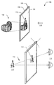
[0013] この例では、表示デバイス104は、視点110から表示デバイスを通して環境108を見るときにユーザに知覚されるように、透明または半透明である。仮想イメージ112は、拡張現実ビューで環境において距離を置いて見えるように表示デバイス104によって表示される近表示オブジェクトとして、コンピューティングデバイス102によって生成することができる。たとえば、ワインボトルおよびグラスの仮想イメージが、環境の物理的に一部であるワイン樽の上に配置されているかのように見えるように生成され得る。
[0013] In this example, the
[0014] 環境108の一部として見えるように投射されている仮想イメージのような近表示オブジェクトに関して、コンピューティングデバイス102のユーザの左眼および右眼114に対する視野角116は異なる。前述のように、視差は、環境内で仮想イメージを見るときに人間の左眼および右眼からのように2つの異なる視線に沿って見られる仮想イメージの視位置の角度差である。しかしながら、奥行きの立体視知覚はユーザによって決定可能ではなく、その理由は、仮想イメージが実際には表示デバイス104上に表示される近表示オブジェクトであるからであり、これは、仮想イメージが投射された位置118で実際に環境の物理的に一部であるとした場合よりもユーザの左眼および右眼114に近い。
[0014] For near-display objects such as virtual images that are projected to appear as part of the
[0015] 図2を参照して説明すると、表示デバイス104は、裸眼立体視の拡張現実ディスプレイのためのイメージング構造を用いて実装することができ、追加のアイウェアを必要としない立体視のためにユーザの左眼および右眼114に提供される仮想イメージの正確な立体視ビューのために、仮想イメージ112を生成することができる。加えて、コンピューティングデバイス102は、環境108ならびに左眼および右眼114のデジタルイメージを捕捉するために利用できる内蔵デジタルカメラ106を含む。環境のデジタルイメージは、環境における仮想イメージと他の近表示オブジェクトとの適正な関係を決定するために利用することができる。ユーザの左眼および右眼のデジタルイメージは、仮想イメージ112などの近表示オブジェクトの表示位置との相互関係において眼の位置を追跡するために利用することができる。
[0015] Referring to FIG. 2, the
[0016] 図2は、本明細書に記載の実施形態による、図1を参照して説明した表示デバイス104などの裸眼立体拡張現実ディスプレイを実装するために利用することができる例示的イメージング構造200を示す。例示的イメージング構造200は、切替え可能ブラッグ格子(SBG)を用いて実装されるような切替え可能回折素子204を含む、シースルー反射導波路202を用いて実装される。切替え可能ブラッグ格子は、SBG Labsにより製造されており、アクティブにされたときに高い回折効率を示し、また非アクティブにされたときに光透過性を示す、サブミリ秒の切替え速度を有するものとして説明される。SBGは、ホログラフィック高分子分散液晶を利用しており、オフに切り替えられると、液晶の屈折率が導波路の周囲のポリマーの屈折率とほぼ一致し、その結果SBGが表示光に実質的に透過的になる。SBGがオンに切り替えられると、液晶は導波管のポリマーと異なる屈折率を有し、仮想イメージの光が回折されて表示デバイスに表示される。
[0016] FIG. 2 illustrates an
[0017] シースルー反射導波路202は、コンピューティングデバイス102のイメージングユニットにより生成され(図1を参照して説明したように)ユーザに見られるように投射される仮想イメージ112の可視光206の内部反射のために実装される表示光学部品である。導波路はまた、ユーザが見るための周囲環境からの光を通す。208に示すように、表示デバイス104が、左眼212と右眼124の瞳の間の瞳孔間距離(IPD)210より広い場合、左眼用の表示領域218におけるα°〜θ°の視野216は、右眼用の表示領域222におけるα°〜θ°の視野220と同じである。これは、一般に両眼オーバーラップと呼ばれ、表示サイズ、および視距離の減少とともに(すなわちユーザへの表示が近づくほど)、増大する。左眼と右眼の間の光線追跡垂直二等分線224も示されており、垂直二等分線は、表示領域218を含む、左眼212により見られるディスプレイの左エリアを確定し、表示領域222を含む、右眼214により見られるディスプレイの右エリアを確定する。
[0017] The see-through
[0018] 導波路222に組み込まれた切替え可能回折素子204(たとえばSBG)は、素子層間に電位を印加することによりオンに切り替えられ、電位を除去することによりオフに切り替えられる。イメージング構造200は、切替え可能回折素子204を選択的にアクティブにするように制御可能な素子駆動回路226(部分的にのみ図示する)を含むことができる。素子駆動回路226は、表示デバイス104の表示領域として、個別の切替え可能回折素子および/またはグループの切替え可能回折素子を制御するように実装することができる。イメージング構造200の導電層は、左眼表示領域218および右眼表示領域222のような表示領域において、切替え可能回折素子を制御するために選択的にアクティブにされる区画に分割され得る。
[0018] The switchable diffractive element 204 (eg, SBG) incorporated in the
[0019] 実施形態において、イメージング構造200の導波路202に組み込まれた切替え可能回折素子204は、230で複数の重なったSBGの例で示されるように、積層素子228のセット内に構成されてよい。さらに232で示されるように、積層素子228のセット内の切替え可能回折素子204の各々が、異なる視野で仮想イメージの光を回折させる。積層素子のセット内の切替え可能回折素子の各々により投射される異なる視野は、表示デバイス104のアクティブにされた表示領域にわたる連続的視野全体として組み合わさることができる。イメージング構造200の切替え可能回折素子204としてSBGを含む実装形態では、各SBGが、表示デバイスと同期された小さな視野を投射し、連続的視野は、(たとえば、積層素子のセット内の)各SBGを連続的にオンに切り替えることによって生成される。切替え可能回折素子204は、人間が検知できるより速く切り替わり、視野が、別々の表示ではなく1つの連続する表示として知覚される。
[0019] In an embodiment, the switchable
[0020] 図3は、図1および2を参照して示し説明したコンピューティングデバイス102の例を示す。コンピューティングデバイスは、図2を参照して説明したように、イメージング構造200を用いて実装される裸眼立体拡張現実ディスプレイ(たとえば、表示デバイス104)を含む。表示デバイス104は、イメージング構造の導波路202に組み込まれた切替え可能回折素子204の構成に基づいて、表示領域300に区分される。表示デバイスの表示領域は、図1に示されるように、環境108において距離を置いて見える仮想イメージ112の正確な立体視ビューを補正するために有効に表示デバイスの表示領域を個別に制御可能である。表示デバイスのイメージング構造は、仮想イメージの表現を、ユーザが右眼で見るための第1の表示領域に表示し、仮想イメージの異なる表現を、ユーザが左眼で見るための第2の表示領域に表示するように制御され得る。
[0020] FIG. 3 shows an example of a
[0021] コンピューティングデバイス102は、イメージングシステム302を含み、イメージングシステム302は、表示デバイスを通して可視である、環境108において距離を置いて見える近表示オブジェクトとして、表示デバイス104上に表示するための仮想イメージ112を生成する。イメージングシステム302は、仮想イメージ112の光206を表示デバイスのイメージング構造200のシースルーおよび反射導波路202へ表示および投射するための、任意のタイプの光学要素、レンズ、マイクロ表示パネル、および/または反射素子を用いて実装することができる。
[0021] The
[0022] また、コンピューティングデバイス102は、デバイスのユーザの左眼および右眼のデジタルイメージを捕捉するためのデジタルカメラ106を含む。図1を参照して示し説明したように、コンピューティングデバイス102は、前方と後方の両方の内蔵デジタルカメラ106を含むことができ、それらは、環境108のデジタルイメージ(たとえば、ビデオおよび/または静止イメージ)ならびにデバイスのユーザの左眼および右眼114のデジタルイメ−ジを捕捉するために利用できる。
[0022] The
[0023] コンピューティングデバイス102は、デジタルイメージに基づいてユーザの左眼および右眼114の瞳位置を追跡するための眼追跡システム304を実装する。また、眼追跡システムは、左眼および右眼から表示デバイス104までの距離を決定し、表示デバイスの中心に対する左眼および右眼の視野角を決定するように実装される。眼追跡システムは、左眼および右眼が表示デバイスに対する異なる視平面上にあるかどうかを含めて、表示デバイスに対する左眼および右眼の位置を決定することができ、次いで、表示領域が、相対的な眼の位置に基づいてオンおよび/またはオフに切り替えられる。表示領域の切替えの例については、図4を参照してさらに説明する。
[0023] The
[0024] また、コンピューティングデバイス102は、(たとえば、デジタルカメラで捕捉されたデジタルイメージに加えて、)環境内の実物のオブジェクトと表示デバイス104の位置合わせを可能にするための追加の参照データを提供する、種々のセンサ306を含むことができる。これらのセンサは、GPS受信機および磁気センサ(たとえばコンパス)などの慣性ベースの追跡用の構成要素および/または測位システム構成要素を含み得る。種々のセンサは、さらに、温度センサ、ならびに、コンピューティングデバイスの位置、向き、および加速度を感知するためのMEMSジャイロおよび加速度センサを含む、慣性センサおよび/または姿勢センサの任意の1つまたは組み合わせを含んでよい。加えて、これらのセンサは、周囲環境からのオーディオデータを記録するためのマイクロホン、および拡張現実体験の一部としてのオーディオフィードバックのための出力を含んでよい。
[0024] The
[0025] コンピューティングデバイス102は、イメージングコントローラ308を有し、イメージングコントローラ308は、ソフトウェアアプリケーションとして実装することができ、任意の適切なメモリデバイスまたは電子データストレージなどのコンピュータ可読記憶媒体に記憶される実行可能命令としてコンピューティングデバイス102で維持することができる。加えて、イメージングコントローラは、裸眼立体拡張現実ディスプレイの実施形態を実装するために、コンピューティングデバイスの処理システムによって実行することができる。さらに、コンピューティングデバイスは、処理システムおよびメモリなど種々の構成要素、ならびに図6に示される例示的デバイスを参照してさらに説明されるような任意の数および組み合わせの異なる構成要素を用いて実装され得る。
[0025] The
[0026] また、イメージングコントローラ308が素子駆動回路226を制御し、素子駆動回路226は、イメージングコントローラの入力に基づいて、表示デバイス104のそれぞれの表示領域300における切替え可能回折素子204を選択的にアクティブにする。表示領域は、眼追跡システム304により決定されるような左眼および右眼の位置および動きに基づいて、交互のフレームでオンおよびオフに切り替えることができる。実装形態において、表示デバイスのそれぞれの表示領域内の切替え可能回折素子のアクティブ化は、左眼および右眼の瞳位置、左眼および右眼から表示デバイスまでの距離、ならびに表示デバイスの中心に対する左眼および右眼の視野角に基づいて、制御される(たとえば、オンおよびオフに切り替えられる)。
Further, the imaging controller 308 controls the
[0027] イメージングコントローラ308は、眼追跡システム304が表示デバイスに対する左眼および右眼の位置および動きを決定するにつれて、動的に表示デバイス104の左眼および右眼表示領域300を決定するように実装される。表示領域は、同時に投射されないように能動的に切り替えられ、左眼および右眼に投射される交互の表示領域は、環境における近表示オブジェクトの適正な視野角に対応して配置される近表示オブジェクト(たとえば仮想イメージ112)を促進するための適切なベクトル調整を含む。
[0027] The imaging controller 308 dynamically determines the left eye and right
[0028] イメージングコントローラ308は、図2を参照して示し説明したように、イメージング構造200における切替え可能回折素子204から投射された視野ごとにユーザの左眼と右眼の間の光線追跡垂直二等分線224(単眼位置とも称される)を決定することができる。表示デバイス104は、切替え可能回折素子を用いて実装されるようにタイル状にされるため、各タイルは、新しい視野を表し、左眼および右眼に対する表示領域は、現在の二等分線の眼の位置に対するタイルごとに光線追跡二等分線224を計算することによって決定される。たとえば、切替え可能回折素子204が10°の視野を有する場合、−5°〜+5°の間の光線追跡二等分線が切替え可能回折素子ごとに0°であり、これが、左眼と右眼の間の単眼位置から表示デバイスの表示領域へプロットされる。各切替え可能回折素子の決定された視野に関して、左の表示領域セグメントは左眼について切替え可能であり、右の表示領域セグメントは右眼について切替え可能である。
[0028] The imaging controller 308, as shown and described with reference to FIG. 2, for ray tracing between the user's left eye and right eye for each field of view projected from the switchable
[0029] 同様に、左眼および右眼のための表示領域300は、切替え可能回折素子の他の視野に基づいて決定され得る。たとえば、−15°〜−5°の左および右表示領域セグメントは、10°の光線追跡二等分線に中心化され、これが、左眼と右眼の間の単眼位置から表示デバイスの表示領域へプロットされる。表示領域セグメントは、単眼位置からの光線追跡二等分線に応じて左および/または右にシフトすることができる。これらの表示領域セグメントは、眼追跡システム304により決定されるような左眼および右眼の位置および動きに応じて横にシフトすることができる。実装形態において、表示領域セグメントのサイズは、視距離に応じて変更することができる。より長い視距離では、特にユーザの眼の動きが速い場合、表示デバイスのイメージング構造から投射された光が右眼から左眼に交差する可能性が高い。加えて、速い左眼および右眼の動きが検出される場合、表示領域セグメントをより広く設定して、視野の損失の機会を減らすことができる。
[0029] Similarly, the
[0030] 図4は、図1〜3を参照して説明した表示デバイス104のような裸眼立体拡張現実ディスプレイの例示的実装形態400を示す。この例では、表示デバイス104は、図2を参照して説明したように、素子駆動回路226のそれぞれの電位V1〜V5により能動的に制御される5つの表示領域401〜405に区分される。コンピューティングデバイス102の眼追跡システム304が、ユーザの眼が位置406に位置付けられると決定すると、表示領域401、402、および404の切替え可能回折素子204がオンに切り替えられ、表示領域403および405がオフに切り替えられる。表示領域401および402はともに、表示領域の両方に近い位置のため、左眼のためにオンに切り替えられる。したがって、表示デバイスの約60パーセント(60%)のみが照明され、そうでなければディスプレイ全体を照明するために利用される電力のうちのおよそ40パーセント(40%)が節約される。
FIG. 4 illustrates an
[0031] 同様に、眼追跡システム304が、ユーザの眼が位置408に位置付けられると決定すると、表示領域402、404、および405の切替え可能回折素子204がオンに切り替えられ、表示領域401および403がオフに切り替えられる。表示領域404および405はともに、表示領域の両方に近い位置のため、右眼のためにオンに切り替えられる。加えて、眼追跡システム304が、ユーザの眼が位置410に位置付けられると決定すると、表示領域402、403、および405の切替え可能回折素子204がオンに切り替えられ、表示領域401および404がオフに切り替えられる。表示領域402および403はともに、表示領域の両方に近い位置のため、左眼のためにオンに切り替えられる。
[0031] Similarly, when the
[0032] 裸眼立体拡張現実ディスプレイの1つまたは複数の実施形態による例示的方法500について図5を参照して説明する。一般に、本明細書に記載のサービス、構成要素、モジュール、方法、および動作のいずれも、ソフトウェア、ファームウェア、ハードウェア(たとえば固定論理回路)、手動処理、またはこれらの任意の組み合わせを使用して実装されてよい。例示的方法は、コンピュータ処理システムに対してローカルおよび/またはリモートのコンピュータ可読記憶媒体に記憶された実行可能命令の一般的文脈で説明され得、実装形態はソフトウェアアプリケーション、プログラム、機能等を含んでよい。
[0032] An
[0033] 図5は、裸眼立体拡張現実ディスプレイの例示的方法500を示す。方法が説明される順序は、限定として解釈されるものではなく、方法の動作の任意の数および組み合わせが、方法または代替方法を実装するために任意の順序で組み合わせられてよい。
[0033] FIG. 5 shows an
[0034] 502で、仮想イメージが、表示デバイスに表示するために生成される。たとえば、コンピューティングデバイス102で実装されたイメージングシステム302(図3)が、コンピューティングデバイス102で実装された裸眼立体拡張現実ディスプレイ(たとえば表示デバイス104)(図1)などでの表示のために、仮想イメージ112を生成する。仮想イメージは、拡張現実イメージングのための表示デバイスを通して可視である環境108において距離を置いて見える近表示オブジェクトとして生成される。
[0034] At 502, a virtual image is generated for display on a display device. For example, an imaging system 302 (FIG. 3) implemented with
[0035] 504で、ユーザの眼の位置を捕捉するデジタルイメージに基づいて、ユーザの左眼および右眼の瞳位置が追跡される。たとえば、コンピューティングデバイス102と一体化されたデジタルカメラ106が、コンピューティングデバイスのユーザの左眼および右眼114のデジタルイメージを捕捉し、眼追跡システム304が、デジタルイメージに基づいて左眼および右眼の瞳位置を追跡する。
[0035] At 504, the pupil positions of the user's left eye and right eye are tracked based on the digital image that captures the position of the user's eye. For example, a
[0036] 506で、左眼および右眼から表示デバイスまでの距離が決定される。たとえば、コンピューティングデバイス102の眼追跡システム304が、デジタルカメラ106により捕捉されたデジタルイメージに基づいて、コンピューティングデバイスのユーザの左眼および右眼114から表示デバイス104までの距離を決定する。508で、表示デバイスの中心に対する左眼および右眼の視野角が決定される。たとえば、コンピューティングデバイス102の眼追跡システム304は、デジタルカメラにより捕捉されたデジタルイメージに基づいて、表示デバイス104の中心に対するユーザの左眼および右眼114の視野角116も決定する。
[0036] At 506, distances from the left and right eyes to the display device are determined. For example, the
[0037] 510で、表示デバイスの表示領域内に構成された切替え可能回折素子のアクティブ化が制御される。たとえば、コンピューティングデバイス102のイメージングコントローラ308が、表示デバイス104の表示領域300内に構成された切替え可能回折素子204のアクティブ化を制御する。表示デバイスの表示領域は、環境108において距離を置いて見える仮想イメージ112の正確な立体視ビューを補正するために有効に個別に制御可能である。表示デバイスの表示領域内の切替え可能回折素子は、表示する仮想イメージを投射するために、イメージングコントローラ308からのイメージングコントローラ入力に基づいて選択的にアクティブにされる。さらに、表示ゾーン内の切替え可能回折素子のアクティブ化は、(504で決定された)左眼および右眼114の瞳位置、(506で決定された)左眼および右眼から表示デバイスまでの距離、ならびに(508で決定された)表示デバイスの中心に対する左眼および右眼の視野角116に基づいて制御される。
[0037] At 510, activation of a switchable diffractive element configured in the display area of the display device is controlled. For example, the imaging controller 308 of the
[0038] 512で、アクティブにされた表示領域にわたる連続的視野が生成される。たとえば、コンピューティングデバイス102のイメージングコントローラ308は、素子駆動回路226を制御して積層素子228のセット内の切替え可能回折素子204を選択的にアクティブにし、積層素子のセット内の各切替え可能回折素子204が、異なる視野で仮想イメージ112の光を回折させる(図2の230および232で示されるように)。積層素子のセット内の切替え可能回折素子の各々により投射される異なる視野は、表示デバイスのアクティブにされた表示領域にわたる連続的視野を生成するように組み合わさる。
[0038] At 512, a continuous field of view over the activated display area is generated. For example, the imaging controller 308 of the
[0039] 514で、仮想イメージは、表示デバイスを通して可視である環境において距離を置いて見える近表示オブジェクトとして表示される。たとえば、表示デバイス102で実装された裸眼立体拡張現実ディスプレイ(たとえば表示デバイス104)が、表示デバイスを通して可視である環境108において距離を置いて見える近表示オブジェクトとして、連続的視野上の仮想イメージ112を表示する。仮想イメージ112の表現を、ユーザが右眼214で見るための右眼表示領域222に表示することができ、仮想イメージの異なる表現を、ユーザが左眼212で見るための左眼表示領域218に表示することができる。
[0039] At 514, the virtual image is displayed as a near display object that appears at a distance in an environment that is visible through the display device. For example, an autostereoscopic augmented reality display (eg, display device 104) implemented with
[0040] 図6は、裸眼立体拡張現実ディスプレイ104を実装するコンピューティングデバイス102のような、先の図1〜5を参照して説明したデバイスのいずれかとして実装され得る、例示的デバイス600の種々の構成要素を示す。実施形態において、デバイス600は、任意のタイプのクライアントデバイス、携帯電話、タブレット、コンピューティング、通信、エンターテイメント、ゲーム、メディア再生、および/または他のタイプのデバイスとして実装することができる。
[0040] FIG. 6 illustrates an
[0041] デバイス600は、デバイスに記憶された仮想イメージデータ、ビデオおよびイメージデータ、および他のメディアコンテンツなどのデバイスデータ604の有線および/または無線通信を可能にする、通信デバイス602を含む。デバイスデータは、任意のタイプのオーディオ、ビデオ、および/またはイメージデータを含むことができる。また、通信デバイス602は、セルラー電話通信および/またはネットワークデータ通信のためのトランシーバを含むことができる。
[0041] The
[0042] デバイス600は、デバイス、データネットワーク、および他のデバイスの間の接続および/または通信リンクを提供する、データネットワークインターフェースのような入出力(I/O)インターフェース606も含む。I/Oインターフェースは、デバイス600と一体化され得るデジタルカメラ608のような任意のタイプの構成要素、周辺機器、および/またはアクセサリデバイスにデバイスを結合するために使用することができる。I/Oインターフェースはデータ入力ポートも含み、データ入力ポートを介して、デバイスへのユーザ入力、ならびに任意のコンテンツおよび/またはデータソースから受信される任意のタイプのオーディオ、ビデオ、および/またはイメージデータなど、任意のタイプのデータ、メディアコンテンツ、および/または入力を受信することができる。
[0042] The
[0043] I/Oインターフェース606は、ユーザがマウス、キーボード、リモートコントロールなどの入力デバイスによって課される人工的な制約から解放されて「自然な」方法でデバイスと対話することを可能にする任意のインターフェース技術のような、デバイス600に対するナチュラルユーザインターフェース(NUI)入力もサポートする。ナチュラルユーザインターフェース入力の例は、音声認識、タッチおよびスタイラス認識、オンスクリーンのジェスチャ認識、デバイスに近接するモーションジェスチャ認識、頭、目および環境の認識および追跡、拡張現実および仮想現実システム、ならびにユーザ入力の意図を決定できる任意の他のタイプの可聴、視覚、タッチ、ジェスチャ、および/またはマシンインテリジェンスに依拠し得る。
[0043] The I /
[0044] デバイス600は、実行可能命令を処理する任意のタイプのマイクロプロセッサおよびコントローラなどのハードウェアで少なくとも部分的に実装され得る、処理システム610を含む。処理システムは、集積回路、プログラマブル論理デバイス、1つまたは複数の半導体を使用して形成される論理デバイス、ならびに、システムオンチップ(SoC)として実装されるプロセッサおよびメモリシステムのような他のシリコンおよび/またはハードウェアの実装形態の構成要素を含むことができる。代替または追加として、デバイスは、ソフトウェア、ハードウェア、ファームウェア、または処理および制御回路を用いて実装され得る固定論理回路の任意の1つまたは組み合わせで実装することができる。デバイス600はさらに、デバイス内の種々の構成要素を結合する任意のタイプのシステムバスまたは他のデータおよびコマンド転送システムを含むことができる。システムバスは、異なるバス構造およびアーキテクチャならびに制御およびデータラインの任意の1つまたは組み合わせを含むことができる。
[0044] The
[0045] デバイス600は、コンピューティングデバイスによってアクセス可能で、データおよび実行可能命令(たとえば、ソフトウェアアプリケーション、プログラム、関数など)の持続的な記憶を実現するデータ記憶デバイスのようなコンピュータ可読記憶媒体612も含む。コンピュータ可読記憶媒体の例には、揮発性メモリおよび不揮発性メモリ、固定メディアデバイスおよび取外し可能メディアデバイス、ならびにコンピューティングデバイスのアクセスのためのデータを保持する任意の適切なメモリデバイスまたは電子データストレージが含まれる。コンピュータ読取可能記憶媒体は、種々の実装形態のランダムアクセスメモリ(RAM)、読取り専用メモリ(ROM)、フラッシュメモリ、および種々のメモリデバイス構成の他のタイプの記憶媒体を含むことができる。
[0045] The
[0046] 一般に、コンピュータ可読記憶媒体は、単なる信号伝送、搬送波、または信号それ自体と対照的に、データの持続的および/または非一時的な記憶を可能にする媒体および/またはデバイスを表す。コンピュータ可読信号媒体は、ネットワークを介するなどして命令を送信する信号担持媒体を指すことがある。信号媒体は、コンピュータ読取可能命令を、搬送波や他の伝送機構のような変調データ信号内のデータとして具現化することができる。 [0046] In general, computer-readable storage media refers to media and / or devices that permit persistent and / or non-transitory storage of data, as opposed to merely signal transmission, carrier waves, or the signals themselves. A computer-readable signal medium may refer to a signal-bearing medium that transmits instructions, such as over a network. A signal medium may embody computer readable instructions as data in a modulated data signal such as a carrier wave or other transmission mechanism.
[0047] コンピュータ可読記憶媒体612は、デバイスデータ604、デジタルカメラ608から捕捉されたイメージデータ614、および、コンピュータ可読記憶媒体によりソフトウェアアプリケーションとして保持され処理システム610により実行されるオペレーティングシステムなどの種々のデバイスアプリケーション616のストレージを提供する。この例では、デバイスアプリケーションは、例示的デバイス600がコンピューティングデバイス102として実装されるときなどに、裸眼立体拡張現実ディスプレイの実施形態を実装するイメージングコントローラ618も含む。イメージングコントローラ618の例には、図3を参照して説明したようなコンピューティングデバイス102で実装されるイメージングコントローラ308が含まれる。デバイス600は、GPSトランシーバなどの測位システム620、またはデバイスの全地球的またはナビゲーション位置を決定するために利用できる類似の測位システム構成要素を含むこともできる。
[0047] The computer
[0048] デバイス600は、オーディオデバイス624のためのオーディオデータ、および/または表示デバイス626のための表示データを生成するオーディオおよび/またはビデオシステム622も含む。実施形態において、表示デバイス626は、裸眼立体拡張現実ディスプレイとして実装することができる。オーディオデバイスおよび/または表示デバイスは、見るために表示される仮想イメージなどのオーディオ、ビデオ、表示、および/またはイメージデータを、処理、表示、および/または他の方法でレンダリングする任意のデバイスを含む。実装形態において、オーディオおよび/または表示デバイスは、例示的デバイス600の一体化された構成要素である。あるいは、オーディオデバイスおよび/または表示デバイスは、例示的デバイスの外部の周辺構成要素である。
[0048] The
[0049] 裸眼立体拡張現実ディスプレイの実施形態は、特徴および/または方法に特有の言葉で説明されているが、添付の特許請求の範囲は、説明された具体的な特徴または方法に必ずしも限定されない。むしろ、それらの具体的な特徴および方法は、裸眼立体拡張現実ディスプレイの例示的実装形態として開示されている。 [0049] Although embodiments of autostereoscopic augmented reality displays are described in language specific to the features and / or methods, the appended claims are not necessarily limited to the specific features or methods described. . Rather, their specific features and methods are disclosed as exemplary implementations of autostereoscopic augmented reality displays.
Claims (11)
環境の透視のために構成された導波路であって、前記環境が前記導波路を通して表示されるとき、前記環境において距離を置いて見える近表示オブジェクトとして生成される仮想イメージの光を伝送するようにさらに構成された導波路と、
前記環境の実物のオブジェクトに対して、前記環境内の前記イメージング構造の少なくとも位置および向きに関係する参照データを提供するように構成された、1つ又は複数のセンサと、
前記導波路に組み込まれ、かつ、表示領域内に構成された切替え可能回折素子と
を備え、
前記表示領域はベクトル調整されるものであって、前記ベクトル調整は、前記参照データの一部に基づいて、前記イメージング構造の前記位置および前記向きを構成し、かつ、前記環境において前記距離を置いて見える前記仮想イメージが、前記環境の前記実物のオブジェクトの視野角に関連する正確な視野角で生成されることを可能にし、
切替え可能回折素子は、前記環境において前記距離を置いて見える前記仮想イメージの正確な立体視ビューを補正するために有効に前記表示領域の各部分を個別にアクティブにするように切替え可能である、イメージング構造。 An imaging structure,
A waveguide configured for perspective of an environment so that when the environment is displayed through the waveguide, it transmits light of a virtual image generated as a near display object that is visible at a distance in the environment. A waveguide further configured to:
One or more sensors configured to provide, to a real object of the environment, reference data related to at least the position and orientation of the imaging structure within the environment;
A switchable diffractive element incorporated in the waveguide and configured in a display region;
The display area is an intended to be vector adjustment, the vector adjustment is based on a portion of the reference data, constitute the position and the orientation of the Imaging structure, and the distance in the environment Allowing the virtual image to be viewed to be generated with an accurate viewing angle related to the viewing angle of the real object of the environment;
A switchable diffractive element is switchable to individually activate each portion of the display area effectively to correct an accurate stereoscopic view of the virtual image that appears at the distance in the environment. Imaging structure.
される、請求項1に記載のイメージング構造。 The switchable diffractive element is configured in a set of stacked elements, and each switchable diffractive element in the set of stacked elements is configured to diffract the light of the virtual image with a different field of view. The imaging structure described in 1.
シースルー型表示デバイスであって、裸眼立体拡張現実ディスプレイとして、前記シースルー型表示デバイスを通して可視である環境において距離を置いて見える近表示オブジェクトとして、前記仮想イメージを表示する、シースルー型表示デバイスと、
前記環境の実物のオブジェクトに対して、前記環境内の前記シースルー型表示デバイスの少なくとも位置および向きに関係する参照データを提供するように構成された、1つ又は複数のセンサと、
前記シースルー型表示デバイスの表示領域内に構成された切替え可能回折素子のアクティブ化を制御するように構成されたイメージングコントローラを実装する処理システムとを備え、
前記シースルー型表示デバイスの表示領域はベクトル調整されるものであって、前記ベクトル調整は、前記参照データの一部に基づいて、前記シースルー型表示デバイスの前記位置および前記向きを構成し、かつ、前記環境において前記距離を置いて見える前記仮想イメージが、前記環境の前記実物のオブジェクトの視野角に関連する正確な視野角で生成されることを可能にし、
前記表示領域の各部分が、前記環境において前記距離を置いて見える前記仮想イメージの正確な立体視ビューを補正するために有効に個別に制御可能であるコンピューティングデバイス。 An imaging system configured to generate a virtual image for display;
A see-through type Display devices, as autostereoscopic augmented reality display, the distance as near the display object visible at a in the environment is visible through the see-through Display device for displaying the virtual image, a see-through display device ,
One or more sensors configured to provide reference data related to at least the position and orientation of the see-through display device within the environment for real objects of the environment;
A processing system that implements an imaging controller configured to control activation of a switchable diffractive element configured in a display area of the see-through display device;
The display area of the see-through display device be one that is vector adjustment, the vector adjustment is based on a portion of the reference data, constitute the position and the orientation of the see-through display device, and, Allowing the virtual image that appears at a distance in the environment to be generated with an accurate viewing angle related to the viewing angle of the real object in the environment;
A computing device wherein each portion of the display area is effectively individually controllable to correct an accurate stereoscopic view of the virtual image viewed at a distance in the environment.
前記シースルー型表示デバイスを通して可視である環境において距離を置いて見える近表示オブジェクトとして、前記仮想イメージを表示すること、
前記環境の実物のオブジェクトに対して、前記環境内の前記シースルー型表示デバイスの少なくとも位置および向きに関係する参照データを受け取ること、
前記シースルー型表示デバイスの表示領域内に構成された切替え可能回折素子のアクティブ化を制御すること
を含み、
前記シースルー型表示デバイスの前記表示領域はベクトル調整されるものであって、前記ベクトル調整は、前記参照データの一部に基づいて、前記シースルー型表示デバイスの前記位置および前記向きを構成し、かつ、前記環境において前記距離を置いて見える前記仮想イメージが、前記環境の前記実物のオブジェクトの視野角に関連する正確な視野角で生成されることを可能にし、
前記表示領域の各部分が、前記環境において前記距離を置いて見える前記仮想イメージの正確な立体視ビューを補正するために有効に個別に制御可能である、
方法。 Generating a virtual image for display on a see-through display device;
Displaying the virtual image as a near display object visible at a distance in an environment that is visible through the see-through display device;
Receiving reference data relating to at least a position and an orientation of the see-through display device in the environment for a real object of the environment;
Controlling activation of a switchable diffractive element configured within a display area of the see-through display device;
Wherein the display area of the see-through display device be one that is vector adjustment, the vector adjustment is based on a portion of the reference data, constitute the position and the orientation of the see-through display device, and Allowing the virtual image that appears at a distance in the environment to be generated with an accurate viewing angle related to the viewing angle of the real object in the environment;
Each portion of the display area can be effectively and individually controlled to correct an accurate stereoscopic view of the virtual image that appears at a distance in the environment;
Method.
前記左眼および前記右眼から前記シースルー型表示デバイスまでの距離を決定すること、および、
前記シースルー型表示デバイスの中心に対する前記左眼および前記右眼の視野角を決定すること
をさらに含む、請求項9に記載の方法。 Tracking the pupil position of the user's left eye and right eye based on a digital image that captures the position of the user's eye;
Determining a distance from the left eye and the right eye to the see-through display device; and
The method of claim 9, further comprising determining a viewing angle of the left eye and the right eye relative to a center of the see-through display device.
Applications Claiming Priority (3)
| Application Number | Priority Date | Filing Date | Title |
|---|---|---|---|
| US13/722,917 | 2012-12-20 | ||
| US13/722,917 US10192358B2 (en) | 2012-12-20 | 2012-12-20 | Auto-stereoscopic augmented reality display |
| PCT/US2013/076832 WO2014100549A1 (en) | 2012-12-20 | 2013-12-20 | Auto-stereoscopic augmented reality display |
Publications (3)
| Publication Number | Publication Date |
|---|---|
| JP2016512607A JP2016512607A (en) | 2016-04-28 |
| JP2016512607A5 JP2016512607A5 (en) | 2017-01-05 |
| JP6433914B2 true JP6433914B2 (en) | 2018-12-05 |
Family
ID=49958700
Family Applications (1)
| Application Number | Title | Priority Date | Filing Date |
|---|---|---|---|
| JP2015549765A Active JP6433914B2 (en) | 2012-12-20 | 2013-12-20 | Autostereoscopic augmented reality display |
Country Status (11)
| Country | Link |
|---|---|
| US (1) | US10192358B2 (en) |
| EP (1) | EP2936237A1 (en) |
| JP (1) | JP6433914B2 (en) |
| KR (1) | KR102139842B1 (en) |
| CN (1) | CN104871068B (en) |
| AU (1) | AU2013361148B2 (en) |
| BR (1) | BR112015012047A8 (en) |
| CA (1) | CA2889727C (en) |
| MX (1) | MX362589B (en) |
| RU (1) | RU2651611C2 (en) |
| WO (1) | WO2014100549A1 (en) |
Families Citing this family (131)
| Publication number | Priority date | Publication date | Assignee | Title |
|---|---|---|---|---|
| GB0522968D0 (en) | 2005-11-11 | 2005-12-21 | Popovich Milan M | Holographic illumination device |
| GB0718706D0 (en) | 2007-09-25 | 2007-11-07 | Creative Physics Ltd | Method and apparatus for reducing laser speckle |
| US11726332B2 (en) | 2009-04-27 | 2023-08-15 | Digilens Inc. | Diffractive projection apparatus |
| US9335604B2 (en) | 2013-12-11 | 2016-05-10 | Milan Momcilo Popovich | Holographic waveguide display |
| US11300795B1 (en) | 2009-09-30 | 2022-04-12 | Digilens Inc. | Systems for and methods of using fold gratings coordinated with output couplers for dual axis expansion |
| US8233204B1 (en) | 2009-09-30 | 2012-07-31 | Rockwell Collins, Inc. | Optical displays |
| US11320571B2 (en) | 2012-11-16 | 2022-05-03 | Rockwell Collins, Inc. | Transparent waveguide display providing upper and lower fields of view with uniform light extraction |
| US10795160B1 (en) | 2014-09-25 | 2020-10-06 | Rockwell Collins, Inc. | Systems for and methods of using fold gratings for dual axis expansion |
| US8659826B1 (en) | 2010-02-04 | 2014-02-25 | Rockwell Collins, Inc. | Worn display system and method without requiring real time tracking for boresight precision |
| WO2012136970A1 (en) | 2011-04-07 | 2012-10-11 | Milan Momcilo Popovich | Laser despeckler based on angular diversity |
| US10670876B2 (en) | 2011-08-24 | 2020-06-02 | Digilens Inc. | Waveguide laser illuminator incorporating a despeckler |
| WO2016020630A2 (en) | 2014-08-08 | 2016-02-11 | Milan Momcilo Popovich | Waveguide laser illuminator incorporating a despeckler |
| EP2995986B1 (en) | 2011-08-24 | 2017-04-12 | Rockwell Collins, Inc. | Data display |
| US9599813B1 (en) | 2011-09-30 | 2017-03-21 | Rockwell Collins, Inc. | Waveguide combiner system and method with less susceptibility to glare |
| US9366864B1 (en) | 2011-09-30 | 2016-06-14 | Rockwell Collins, Inc. | System for and method of displaying information without need for a combiner alignment detector |
| US9715067B1 (en) | 2011-09-30 | 2017-07-25 | Rockwell Collins, Inc. | Ultra-compact HUD utilizing waveguide pupil expander with surface relief gratings in high refractive index materials |
| US8634139B1 (en) | 2011-09-30 | 2014-01-21 | Rockwell Collins, Inc. | System for and method of catadioptric collimation in a compact head up display (HUD) |
| US9223138B2 (en) | 2011-12-23 | 2015-12-29 | Microsoft Technology Licensing, Llc | Pixel opacity for augmented reality |
| WO2013102759A2 (en) | 2012-01-06 | 2013-07-11 | Milan Momcilo Popovich | Contact image sensor using switchable bragg gratings |
| US9297996B2 (en) | 2012-02-15 | 2016-03-29 | Microsoft Technology Licensing, Llc | Laser illumination scanning |
| US9779643B2 (en) | 2012-02-15 | 2017-10-03 | Microsoft Technology Licensing, Llc | Imaging structure emitter configurations |
| US9726887B2 (en) | 2012-02-15 | 2017-08-08 | Microsoft Technology Licensing, Llc | Imaging structure color conversion |
| US9368546B2 (en) | 2012-02-15 | 2016-06-14 | Microsoft Technology Licensing, Llc | Imaging structure with embedded light sources |
| US9093012B2 (en) * | 2012-02-29 | 2015-07-28 | Lenovo (Beijing) Co., Ltd. | Operation mode switching method and electronic device |
| US9578318B2 (en) | 2012-03-14 | 2017-02-21 | Microsoft Technology Licensing, Llc | Imaging structure emitter calibration |
| US11068049B2 (en) | 2012-03-23 | 2021-07-20 | Microsoft Technology Licensing, Llc | Light guide display and field of view |
| US9523852B1 (en) | 2012-03-28 | 2016-12-20 | Rockwell Collins, Inc. | Micro collimator system and method for a head up display (HUD) |
| US10191515B2 (en) | 2012-03-28 | 2019-01-29 | Microsoft Technology Licensing, Llc | Mobile device light guide display |
| US9558590B2 (en) | 2012-03-28 | 2017-01-31 | Microsoft Technology Licensing, Llc | Augmented reality light guide display |
| US9717981B2 (en) | 2012-04-05 | 2017-08-01 | Microsoft Technology Licensing, Llc | Augmented reality and physical games |
| CN106125308B (en) | 2012-04-25 | 2019-10-25 | 罗克韦尔柯林斯公司 | Device and method for displaying images |
| WO2013167864A1 (en) | 2012-05-11 | 2013-11-14 | Milan Momcilo Popovich | Apparatus for eye tracking |
| US10502876B2 (en) | 2012-05-22 | 2019-12-10 | Microsoft Technology Licensing, Llc | Waveguide optics focus elements |
| US8989535B2 (en) | 2012-06-04 | 2015-03-24 | Microsoft Technology Licensing, Llc | Multiple waveguide imaging structure |
| KR20140045801A (en) * | 2012-10-09 | 2014-04-17 | 삼성전자주식회사 | Transparent display apparatus and controlling method thereof |
| US9933684B2 (en) | 2012-11-16 | 2018-04-03 | Rockwell Collins, Inc. | Transparent waveguide display providing upper and lower fields of view having a specific light output aperture configuration |
| US9573277B2 (en) * | 2013-04-15 | 2017-02-21 | Alan Rosen | Intelligent visual humanoid robot and computer vision system programmed to perform visual artificial intelligence processes |
| US9674413B1 (en) | 2013-04-17 | 2017-06-06 | Rockwell Collins, Inc. | Vision system and method having improved performance and solar mitigation |
| US10209517B2 (en) | 2013-05-20 | 2019-02-19 | Digilens, Inc. | Holographic waveguide eye tracker |
| US9727772B2 (en) | 2013-07-31 | 2017-08-08 | Digilens, Inc. | Method and apparatus for contact image sensing |
| US9244281B1 (en) | 2013-09-26 | 2016-01-26 | Rockwell Collins, Inc. | Display system and method using a detached combiner |
| US10732407B1 (en) | 2014-01-10 | 2020-08-04 | Rockwell Collins, Inc. | Near eye head up display system and method with fixed combiner |
| US9519089B1 (en) | 2014-01-30 | 2016-12-13 | Rockwell Collins, Inc. | High performance volume phase gratings |
| US9244280B1 (en) | 2014-03-25 | 2016-01-26 | Rockwell Collins, Inc. | Near eye display system and method for display enhancement or redundancy |
| JP6329792B2 (en) * | 2014-03-26 | 2018-05-23 | オリンパス株式会社 | Display device |
| CA3124368C (en) * | 2014-05-30 | 2023-04-25 | Magic Leap, Inc. | Methods and systems for generating virtual content display with a virtual or augmented reality apparatus |
| US9304235B2 (en) | 2014-07-30 | 2016-04-05 | Microsoft Technology Licensing, Llc | Microfabrication |
| US10592080B2 (en) | 2014-07-31 | 2020-03-17 | Microsoft Technology Licensing, Llc | Assisted presentation of application windows |
| US10254942B2 (en) | 2014-07-31 | 2019-04-09 | Microsoft Technology Licensing, Llc | Adaptive sizing and positioning of application windows |
| US10678412B2 (en) | 2014-07-31 | 2020-06-09 | Microsoft Technology Licensing, Llc | Dynamic joint dividers for application windows |
| WO2016020632A1 (en) | 2014-08-08 | 2016-02-11 | Milan Momcilo Popovich | Method for holographic mastering and replication |
| WO2016042283A1 (en) | 2014-09-19 | 2016-03-24 | Milan Momcilo Popovich | Method and apparatus for generating input images for holographic waveguide displays |
| US9494799B2 (en) * | 2014-09-24 | 2016-11-15 | Microsoft Technology Licensing, Llc | Waveguide eye tracking employing switchable diffraction gratings |
| US9715110B1 (en) | 2014-09-25 | 2017-07-25 | Rockwell Collins, Inc. | Automotive head up display (HUD) |
| US10088675B1 (en) | 2015-05-18 | 2018-10-02 | Rockwell Collins, Inc. | Turning light pipe for a pupil expansion system and method |
| WO2016046514A1 (en) | 2014-09-26 | 2016-03-31 | LOKOVIC, Kimberly, Sun | Holographic waveguide opticaltracker |
| CN104601974A (en) * | 2014-12-30 | 2015-05-06 | 深圳市亿思达科技集团有限公司 | Eye-tracking-based holographic display and holographic display device |
| CN111323867A (en) | 2015-01-12 | 2020-06-23 | 迪吉伦斯公司 | Environmentally isolated waveguide display |
| EP3245551B1 (en) | 2015-01-12 | 2019-09-18 | DigiLens Inc. | Waveguide light field displays |
| US10039975B2 (en) * | 2015-01-13 | 2018-08-07 | Disney Enterprises, Inc. | Techniques for representing imaginary participants in an immersive play environment |
| CN107533137A (en) | 2015-01-20 | 2018-01-02 | 迪吉伦斯公司 | Holographical wave guide laser radar |
| US9970631B2 (en) * | 2015-01-20 | 2018-05-15 | Benq Materials Corporation | One-way vision window system |
| US10782453B2 (en) * | 2015-01-21 | 2020-09-22 | Tesseland, Llc | Display devices with reflectors |
| US9429692B1 (en) | 2015-02-09 | 2016-08-30 | Microsoft Technology Licensing, Llc | Optical components |
| US9372347B1 (en) | 2015-02-09 | 2016-06-21 | Microsoft Technology Licensing, Llc | Display system |
| US10018844B2 (en) | 2015-02-09 | 2018-07-10 | Microsoft Technology Licensing, Llc | Wearable image display system |
| US9513480B2 (en) | 2015-02-09 | 2016-12-06 | Microsoft Technology Licensing, Llc | Waveguide |
| US11086216B2 (en) | 2015-02-09 | 2021-08-10 | Microsoft Technology Licensing, Llc | Generating electronic components |
| US9423360B1 (en) | 2015-02-09 | 2016-08-23 | Microsoft Technology Licensing, Llc | Optical components |
| US9535253B2 (en) | 2015-02-09 | 2017-01-03 | Microsoft Technology Licensing, Llc | Display system |
| US10317677B2 (en) | 2015-02-09 | 2019-06-11 | Microsoft Technology Licensing, Llc | Display system |
| US9827209B2 (en) | 2015-02-09 | 2017-11-28 | Microsoft Technology Licensing, Llc | Display system |
| US9632226B2 (en) | 2015-02-12 | 2017-04-25 | Digilens Inc. | Waveguide grating device |
| WO2016146963A1 (en) | 2015-03-16 | 2016-09-22 | Popovich, Milan, Momcilo | Waveguide device incorporating a light pipe |
| WO2016156776A1 (en) | 2015-03-31 | 2016-10-06 | Milan Momcilo Popovich | Method and apparatus for contact image sensing |
| US11366316B2 (en) | 2015-05-18 | 2022-06-21 | Rockwell Collins, Inc. | Head up display (HUD) using a light pipe |
| US10247943B1 (en) | 2015-05-18 | 2019-04-02 | Rockwell Collins, Inc. | Head up display (HUD) using a light pipe |
| US10126552B2 (en) | 2015-05-18 | 2018-11-13 | Rockwell Collins, Inc. | Micro collimator system and method for a head up display (HUD) |
| US10108010B2 (en) | 2015-06-29 | 2018-10-23 | Rockwell Collins, Inc. | System for and method of integrating head up displays and head down displays |
| EP3359999A1 (en) | 2015-10-05 | 2018-08-15 | Popovich, Milan Momcilo | Waveguide display |
| RU2610620C1 (en) * | 2015-10-16 | 2017-02-14 | Владимир Петрович Куклев | Stereoscopic indicator displaying three-dimensional information through windscreen of aircraft |
| US20170161949A1 (en) * | 2015-12-08 | 2017-06-08 | GM Global Technology Operations LLC | Holographic waveguide hud side view display |
| US10598932B1 (en) | 2016-01-06 | 2020-03-24 | Rockwell Collins, Inc. | Head up display for integrating views of conformally mapped symbols and a fixed image source |
| EP3398007A1 (en) | 2016-02-04 | 2018-11-07 | DigiLens, Inc. | Holographic waveguide optical tracker |
| JP6895451B2 (en) | 2016-03-24 | 2021-06-30 | ディジレンズ インコーポレイテッド | Methods and Devices for Providing Polarized Selective Holography Waveguide Devices |
| JP6734933B2 (en) | 2016-04-11 | 2020-08-05 | ディジレンズ インコーポレイテッド | Holographic Waveguide Device for Structured Light Projection |
| CN109153355B (en) * | 2016-05-26 | 2022-03-22 | 金泰克斯公司 | Waveguide mirror display system |
| US10353202B2 (en) | 2016-06-09 | 2019-07-16 | Microsoft Technology Licensing, Llc | Wrapped waveguide with large field of view |
| KR102582841B1 (en) * | 2016-07-07 | 2023-09-27 | 삼성디스플레이 주식회사 | Display device |
| US11006090B2 (en) * | 2016-08-05 | 2021-05-11 | University Of Rochester | Virtual window |
| JP6813666B2 (en) | 2016-08-22 | 2021-01-13 | マジック リープ, インコーポレイテッドMagic Leap,Inc. | Multi-layer diffraction eyepiece |
| US10108144B2 (en) * | 2016-09-16 | 2018-10-23 | Microsoft Technology Licensing, Llc | Holographic wide field of view display |
| US20180089854A1 (en) * | 2016-09-26 | 2018-03-29 | Korea Electronics Technology Institute | 3d transparent display device and operating method thereof |
| US10311615B2 (en) * | 2016-09-27 | 2019-06-04 | Samsung Electronics Co., Ltd. | Method and device for providing augmented reality image and recording medium storing program to execute the method |
| WO2018071395A1 (en) | 2016-10-13 | 2018-04-19 | Gentex Corporation | Waveguide mirror display system |
| CN106445167B (en) * | 2016-10-20 | 2019-09-20 | 网易(杭州)网络有限公司 | Simple eye visual field is adaptive to match method of adjustment and device, wear-type visual device |
| EP3548939A4 (en) | 2016-12-02 | 2020-11-25 | DigiLens Inc. | Waveguide device with uniform output illumination |
| US10545346B2 (en) | 2017-01-05 | 2020-01-28 | Digilens Inc. | Wearable heads up displays |
| EP4250242A3 (en) | 2017-01-23 | 2023-11-29 | Magic Leap, Inc. | Eyepiece for virtual, augmented, or mixed reality systems |
| US10295824B2 (en) | 2017-01-26 | 2019-05-21 | Rockwell Collins, Inc. | Head up display with an angled light pipe |
| IL269085B2 (en) | 2017-03-21 | 2023-12-01 | Magic Leap Inc | Stacked waveguides having different diffraction gratings for combined field of view |
| TW201902412A (en) * | 2017-06-06 | 2019-01-16 | 沈荷芳 | Virtual reality eye detection system and eye detection method thereof |
| CN110809884B (en) * | 2017-06-22 | 2021-09-24 | 林巴克4Pi有限公司 | Visual display utilizing temporal multiplexing for stereoscopic views |
| CN107092097B (en) * | 2017-06-22 | 2019-04-05 | 京东方科技集团股份有限公司 | Naked eye 3D display method, apparatus and terminal device |
| US10338400B2 (en) | 2017-07-03 | 2019-07-02 | Holovisions LLC | Augmented reality eyewear with VAPE or wear technology |
| US10859834B2 (en) | 2017-07-03 | 2020-12-08 | Holovisions | Space-efficient optical structures for wide field-of-view augmented reality (AR) eyewear |
| CN116149058A (en) | 2017-10-16 | 2023-05-23 | 迪吉伦斯公司 | System and method for multiplying image resolution of pixellated display |
| WO2019136476A1 (en) | 2018-01-08 | 2019-07-11 | Digilens, Inc. | Waveguide architectures and related methods of manufacturing |
| JP7404243B2 (en) | 2018-01-08 | 2023-12-25 | ディジレンズ インコーポレイテッド | Systems and methods for high-throughput recording of holographic gratings in waveguide cells |
| US10459237B2 (en) * | 2018-02-01 | 2019-10-29 | Dell Products L.P. | System, head mounted device (HMD) and method for adjusting a position of an HMD worn by a user |
| CN112088332A (en) | 2018-03-16 | 2020-12-15 | 迪吉伦斯公司 | Holographic waveguides including birefringence control and methods for their manufacture |
| US10761256B2 (en) | 2018-04-16 | 2020-09-01 | Samsung Electronics Co., Ltd. | Backlight unit providing uniform light and display apparatus including the same |
| CN108600742B (en) * | 2018-05-17 | 2020-03-20 | 苏州科技大学 | Central eye testing system and method based on three-dimensional display |
| CN108648223A (en) * | 2018-05-17 | 2018-10-12 | 苏州科技大学 | Scene reconstruction method based on median eye and reconfiguration system |
| EP3807708A1 (en) * | 2018-06-15 | 2021-04-21 | Continental Automotive GmbH | Apparatus for generating a virtual image having a variable projection distance |
| WO2020023779A1 (en) | 2018-07-25 | 2020-01-30 | Digilens Inc. | Systems and methods for fabricating a multilayer optical structure |
| US11036048B2 (en) * | 2018-10-03 | 2021-06-15 | Project Whitecard Digital Inc. | Virtual reality system and method for displaying on a real-world display a viewable portion of a source file projected on an inverse spherical virtual screen |
| KR102172612B1 (en) * | 2018-11-22 | 2020-11-02 | 한국전자기술연구원 | Method for Generating Eye-Boxes with Wide Vertical Field of View in Lightguide based Image Providing Apparatus |
| US11357593B2 (en) | 2019-01-10 | 2022-06-14 | Covidien Lp | Endoscopic imaging with augmented parallax |
| CN109785445B (en) * | 2019-01-22 | 2024-03-08 | 京东方科技集团股份有限公司 | Interaction method, device, system and computer readable storage medium |
| WO2020168348A1 (en) | 2019-02-15 | 2020-08-20 | Digilens Inc. | Methods and apparatuses for providing a holographic waveguide display using integrated gratings |
| CN113728258A (en) | 2019-03-12 | 2021-11-30 | 迪吉伦斯公司 | Holographic waveguide backlight and related methods of manufacture |
| EP3933490A4 (en) * | 2019-03-13 | 2022-05-04 | Lg Chem, Ltd. | Diffractive light guide plate |
| KR20220016990A (en) | 2019-06-07 | 2022-02-10 | 디지렌즈 인코포레이티드. | Waveguides incorporating transmission and reflection gratings and related manufacturing methods |
| CN114341729A (en) | 2019-07-29 | 2022-04-12 | 迪吉伦斯公司 | Method and apparatus for multiplying image resolution and field of view of a pixelated display |
| WO2021040083A1 (en) * | 2019-08-28 | 2021-03-04 | 엘지전자 주식회사 | Head-wearable electronic device |
| WO2021041949A1 (en) | 2019-08-29 | 2021-03-04 | Digilens Inc. | Evacuating bragg gratings and methods of manufacturing |
| KR20210137340A (en) * | 2020-05-08 | 2021-11-17 | 삼성디스플레이 주식회사 | Display device |
| CN116075882A (en) * | 2020-07-13 | 2023-05-05 | 英商邦腾科技有限公司 | System and method for real-time LED viewing angle correction |
| US11586286B1 (en) | 2022-05-18 | 2023-02-21 | Bank Of America Corporation | System and method for navigating on an augmented reality display |
| US11720380B1 (en) | 2022-05-18 | 2023-08-08 | Bank Of America Corporation | System and method for updating augmented reality navigation instructions based on a detected error |
Family Cites Families (464)
| Publication number | Priority date | Publication date | Assignee | Title |
|---|---|---|---|---|
| US3410774A (en) | 1965-10-23 | 1968-11-12 | Ibm | Method and apparatus for reverse sputtering selected electrically exposed areas of a cathodically biased workpiece |
| US3906528A (en) | 1970-06-29 | 1975-09-16 | Polaroid Corp | Photographic composing aid enclosed within a camera handle |
| US3836258A (en) | 1972-12-15 | 1974-09-17 | Grumman Aerospace Corp | Angular orientation measuring apparatus |
| US3971065A (en) | 1975-03-05 | 1976-07-20 | Eastman Kodak Company | Color imaging array |
| US4711512A (en) | 1985-07-12 | 1987-12-08 | Environmental Research Institute Of Michigan | Compact head-up display |
| US4822145A (en) | 1986-05-14 | 1989-04-18 | Massachusetts Institute Of Technology | Method and apparatus utilizing waveguide and polarized light for display of dynamic images |
| US4799050A (en) | 1986-10-23 | 1989-01-17 | Litton Systems Canada Limited | Full color liquid crystal display |
| US5146355A (en) | 1986-10-23 | 1992-09-08 | Litton Systems Canada Limited | Transflective mode liquid crystal display with phosphor illumination |
| JPS6442599U (en) | 1987-09-02 | 1989-03-14 | ||
| JPH07101259B2 (en) | 1988-05-10 | 1995-11-01 | シャープ株式会社 | 3D image display device |
| DE68909553T2 (en) | 1988-10-21 | 1994-01-27 | Thomson Csf | Optical collimation system for a helmet view indicator. |
| JPH02227340A (en) | 1989-03-01 | 1990-09-10 | Hitachi Ltd | Terminal unit |
| JP3000621B2 (en) | 1990-05-17 | 2000-01-17 | ソニー株式会社 | Visual aid |
| US5252950A (en) | 1991-12-20 | 1993-10-12 | Apple Computer, Inc. | Display with rangefinder |
| US5543588A (en) | 1992-06-08 | 1996-08-06 | Synaptics, Incorporated | Touch pad driven handheld computing device |
| US6008781A (en) | 1992-10-22 | 1999-12-28 | Board Of Regents Of The University Of Washington | Virtual retinal display |
| US5491580A (en) | 1992-12-17 | 1996-02-13 | The United States Of America As Represented By The Secretary Of The Air Force | High power multilayer stack quarter wave plate |
| US5359444A (en) | 1992-12-24 | 1994-10-25 | Motorola, Inc. | Auto-focusing optical apparatus |
| US5309169A (en) | 1993-02-01 | 1994-05-03 | Honeywell Inc. | Visor display with fiber optic faceplate correction |
| JPH06308918A (en) | 1993-04-21 | 1994-11-04 | Fujitsu Ltd | Control method for displaying screen and control device for displaying screen |
| US5583609A (en) | 1993-04-23 | 1996-12-10 | Nikon Corporation | Projection exposure apparatus |
| US5457574A (en) | 1993-05-06 | 1995-10-10 | Dimension Technologies Inc. | Autostereoscopic display with high power efficiency |
| US5455458A (en) | 1993-08-09 | 1995-10-03 | Hughes Aircraft Company | Phase change cooling of semiconductor power modules |
| US5459611A (en) | 1993-08-18 | 1995-10-17 | Hewlett-Packard Company | Beam splitter/combiner with path length compensator and method for making the same |
| JP3396062B2 (en) | 1993-08-26 | 2003-04-14 | オリンパス光学工業株式会社 | Image display device |
| US5455882A (en) | 1993-09-29 | 1995-10-03 | Associated Universities, Inc. | Interactive optical panel |
| EP0724758A4 (en) | 1993-10-07 | 1998-03-04 | Virtual Vision Inc | Binocular head mounted display system |
| US5991087A (en) | 1993-11-12 | 1999-11-23 | I-O Display System Llc | Non-orthogonal plate in a virtual reality or heads up display |
| US5614941A (en) | 1993-11-24 | 1997-03-25 | Hines; Stephen P. | Multi-image autostereoscopic imaging system |
| JP3020790B2 (en) | 1993-12-28 | 2000-03-15 | 株式会社日立製作所 | Heat pipe type cooling device and vehicle control device using the same |
| JPH07311303A (en) | 1994-05-16 | 1995-11-28 | Asahi Optical Co Ltd | Luminous flux splitting element |
| US5714967A (en) | 1994-05-16 | 1998-02-03 | Olympus Optical Co., Ltd. | Head-mounted or face-mounted image display apparatus with an increased exit pupil |
| US5673146A (en) | 1994-08-09 | 1997-09-30 | Kelly; Shawn L. | Binocular imaging system |
| US5483307A (en) | 1994-09-29 | 1996-01-09 | Texas Instruments, Inc. | Wide field of view head-mounted display |
| JP3235762B2 (en) | 1994-12-06 | 2001-12-04 | 日本電信電話株式会社 | 3D display device |
| GB2296617A (en) | 1994-12-29 | 1996-07-03 | Sharp Kk | Observer tracking autosteroscopic display |
| JPH08190640A (en) | 1995-01-12 | 1996-07-23 | Hitachi Ltd | Information display method and information provision system |
| JP3433558B2 (en) | 1995-02-28 | 2003-08-04 | ソニー株式会社 | Display device |
| US5648643A (en) | 1995-06-16 | 1997-07-15 | Knowles; Terence J. | Acoustic wave touch panel with inlayed, etched arrays and method of making the panel |
| US6481851B1 (en) | 1995-09-20 | 2002-11-19 | Videotronic Systems | Adjustable contrast reflected display system |
| GB2306231A (en) | 1995-10-13 | 1997-04-30 | Sharp Kk | Patterned optical polarising element |
| US5579830A (en) | 1995-11-28 | 1996-12-03 | Hudson Products Corporation | Passive cooling of enclosures using heat pipes |
| US5771320A (en) | 1996-04-30 | 1998-06-23 | Wavefront Research, Inc. | Optical switching and routing system |
| US5737171A (en) | 1996-07-15 | 1998-04-07 | International Business Machines Corporation | Switched management of thermal impedence to reduce temperature excursions |
| US5856842A (en) | 1996-08-26 | 1999-01-05 | Kaiser Optical Systems Corporation | Apparatus facilitating eye-contact video communications |
| US5886822A (en) | 1996-10-08 | 1999-03-23 | The Microoptical Corporation | Image combining system for eyeglasses and face masks |
| CA2270247C (en) | 1996-11-12 | 2007-04-10 | Yair David | Optical system for alternative or simultaneous direction of light originating from two scenes to the eye of a viewer |
| US5777715A (en) | 1997-01-21 | 1998-07-07 | Allen Vision Systems, Inc. | Low vision rehabilitation system |
| JPH10232626A (en) * | 1997-02-20 | 1998-09-02 | Canon Inc | Stereoscopic image display device |
| US5982553A (en) | 1997-03-20 | 1999-11-09 | Silicon Light Machines | Display device incorporating one-dimensional grating light-valve array |
| US6188427B1 (en) | 1997-04-23 | 2001-02-13 | Texas Instruments Incorporated | Illumination system having an intensity calibration system |
| US5925261A (en) | 1997-05-21 | 1999-07-20 | Seagate Technology, Inc. | Method for fabricating a taper on a recording head slider |
| US6144439A (en) | 1997-07-29 | 2000-11-07 | Kaiser Electro-Optics, Inc. | Method and apparatus for reducing ghost images with a tilted cholesteric liquid crystal panel |
| EP1004052A4 (en) | 1997-08-11 | 2000-11-08 | Telcordia Tech Inc | Apparatus and method for creating and displaying planar virtual images |
| US5940149A (en) | 1997-12-11 | 1999-08-17 | Minnesota Mining And Manufacturing Company | Planar polarizer for LCD projectors |
| AU3052499A (en) | 1998-04-02 | 1999-10-25 | Elop Electro-Optics Industries Ltd. | Holographic optical devices |
| US20040108971A1 (en) | 1998-04-09 | 2004-06-10 | Digilens, Inc. | Method of and apparatus for viewing an image |
| US6734838B1 (en) | 1998-05-18 | 2004-05-11 | Dimension Technologies Inc. | Enhanced resolution for image generation |
| JPH11326827A (en) | 1998-05-20 | 1999-11-26 | Sony Corp | Method and device for reducing coherence of light and method and device for illumination |
| US7015876B1 (en) | 1998-06-03 | 2006-03-21 | Lear Corporation | Heads-up display with improved contrast |
| US6271808B1 (en) | 1998-06-05 | 2001-08-07 | Silicon Light Machines | Stereo head mounted display using a single display device |
| JP2000013818A (en) | 1998-06-23 | 2000-01-14 | Nec Corp | Stereoscopic display device and stereoscopic display method |
| US6741788B2 (en) | 1999-07-01 | 2004-05-25 | Honeywell International Inc | Efficient light distribution system |
| US6366460B1 (en) | 1998-07-27 | 2002-04-02 | Compaq Computer Corporation | Heat dissipation structure for electronic apparatus component |
| CA2278356C (en) | 1998-07-31 | 2005-03-22 | David B. Hall | Optical waveguide sensor system for remote detection |
| AU4976099A (en) * | 1998-10-16 | 2000-05-08 | Digilens Inc. | Autostereoscopic display based on electrically switchable holograms |
| US6964731B1 (en) | 1998-12-21 | 2005-11-15 | Cardinal Cg Company | Soil-resistant coating for glass surfaces |
| JP2000276613A (en) | 1999-03-29 | 2000-10-06 | Sony Corp | Device and method for processing information |
| US6906901B1 (en) | 1999-04-26 | 2005-06-14 | Twinhead International Corp. | Cooling apparatus for integrated circuit |
| US6411512B1 (en) | 1999-06-29 | 2002-06-25 | Delta Engineers | High performance cold plate |
| GB9917591D0 (en) | 1999-07-28 | 1999-09-29 | Marconi Electronic Syst Ltd | Head tracker system |
| US6470289B1 (en) | 1999-08-05 | 2002-10-22 | Compaq Information Technologies Group, L.P. | Independently controlling passive and active cooling in a computer system |
| JP3492251B2 (en) | 1999-09-07 | 2004-02-03 | キヤノン株式会社 | Image input device and image display device |
| US7069975B1 (en) | 1999-09-16 | 2006-07-04 | Raytheon Company | Method and apparatus for cooling with a phase change material and heat pipes |
| US6323970B1 (en) | 1999-09-29 | 2001-11-27 | Digilents, Inc. | Method of producing switchable holograms |
| US6446442B1 (en) | 1999-10-07 | 2002-09-10 | Hydrocool Pty Limited | Heat exchanger for an electronic heat pump |
| US6226178B1 (en) | 1999-10-12 | 2001-05-01 | Dell Usa, L.P. | Apparatus for cooling a heat generating component in a computer |
| US6567101B1 (en) | 1999-10-13 | 2003-05-20 | Gateway, Inc. | System and method utilizing motion input for manipulating a display of data |
| US6909826B2 (en) | 1999-10-28 | 2005-06-21 | Princeton Lightwave, Inc. | Multiple grating optical waveguide monitor |
| KR100703930B1 (en) | 1999-10-29 | 2007-04-05 | 마이크로비젼, 인코퍼레이티드 | Personal display with vision tracking |
| US6466198B1 (en) | 1999-11-05 | 2002-10-15 | Innoventions, Inc. | View navigation and magnification of a hand-held device with a display |
| US6239502B1 (en) | 1999-11-22 | 2001-05-29 | Bae Systems Controls | Phase change assisted heat sink |
| HUP0000532A2 (en) | 2000-02-07 | 2002-03-28 | Optilink Ab | Method and system for recording information on a holographic card |
| US6307142B1 (en) | 2000-04-13 | 2001-10-23 | Hi-Z Technology, Inc. | Combustion heat powered portable electronic device |
| ES2348532T3 (en) | 2000-06-05 | 2010-12-09 | Lumus Ltd | OPTICAL BEAM DILATOR GUIDED BY A SUBSTRATE. |
| JP4701479B2 (en) | 2000-07-05 | 2011-06-15 | ソニー株式会社 | Link information display device and display method thereof |
| US7274383B1 (en) | 2000-07-28 | 2007-09-25 | Clairvoyante, Inc | Arrangement of color pixels for full color imaging devices with simplified addressing |
| US6429930B1 (en) | 2000-09-06 | 2002-08-06 | Accent Optical Technologies, Inc. | Determination of center of focus by diffraction signature analysis |
| US6554428B2 (en) | 2000-09-07 | 2003-04-29 | I-O Display Systems Llc | Method and apparatus for adjusting optical device to correspond to eye positions |
| US6753828B2 (en) | 2000-09-25 | 2004-06-22 | Siemens Corporated Research, Inc. | System and method for calibrating a stereo optical see-through head-mounted display system for augmented reality |
| US20020044152A1 (en) | 2000-10-16 | 2002-04-18 | Abbott Kenneth H. | Dynamic integration of computer generated and real world images |
| TW556002B (en) | 2000-10-17 | 2003-10-01 | Koninkl Philips Electronics Nv | Light valve and device provided with a light valve |
| US6542307B2 (en) | 2000-10-20 | 2003-04-01 | Three-Five Systems, Inc. | Compact near-eye illumination system |
| US6547416B2 (en) | 2000-12-21 | 2003-04-15 | Koninklijke Philips Electronics N.V. | Faceted multi-chip package to provide a beam of uniform white light from multiple monochrome LEDs |
| US6997241B2 (en) | 2001-01-13 | 2006-02-14 | Enertron, Inc. | Phase-change heat reservoir device for transient thermal management |
| US7191820B2 (en) | 2001-01-26 | 2007-03-20 | Enertron, Inc. | Phase-change heat reservoir device for transient thermal management |
| KR100406945B1 (en) | 2001-02-19 | 2003-11-28 | 삼성전자주식회사 | Wearable display apparatus |
| FR2821439A1 (en) | 2001-02-28 | 2002-08-30 | Koninkl Philips Electronics Nv | APPARATUS COMPRISING A VIEWING UNIT AND VIEWING UNIT SUITABLE FOR SUCH AN APPARATUS |
| JP3769200B2 (en) | 2001-03-06 | 2006-04-19 | インターナショナル・ビジネス・マシーンズ・コーポレーション | Cooling fan control method and apparatus |
| US6919867B2 (en) | 2001-03-29 | 2005-07-19 | Siemens Corporate Research, Inc. | Method and apparatus for augmented reality visualization |
| US6798429B2 (en) | 2001-03-29 | 2004-09-28 | Intel Corporation | Intuitive mobile device interface to virtual spaces |
| US6529331B2 (en) | 2001-04-20 | 2003-03-04 | Johns Hopkins University | Head mounted display with full field of view and high resolution |
| KR20020083737A (en) | 2001-04-30 | 2002-11-04 | 삼성전자 주식회사 | Wearable display system |
| FI117488B (en) | 2001-05-16 | 2006-10-31 | Myorigo Sarl | Browsing information on screen |
| US7053865B2 (en) | 2001-05-31 | 2006-05-30 | Olympus Corporation | 3-D display device |
| US8035612B2 (en) | 2002-05-28 | 2011-10-11 | Intellectual Ventures Holding 67 Llc | Self-contained interactive video display system |
| JP2002365589A (en) | 2001-06-06 | 2002-12-18 | Olympus Optical Co Ltd | Three-dimensional display device |
| US6635999B2 (en) | 2001-06-08 | 2003-10-21 | Richard S. Belliveau | Method and apparatus for controlling the temperature of a multiparameter light and/or a component thereof using orientation and/or parameter information |
| JP3789321B2 (en) | 2001-06-20 | 2006-06-21 | 日本電信電話株式会社 | Display method and display device |
| US7009163B2 (en) | 2001-06-22 | 2006-03-07 | Orbotech Ltd. | High-sensitivity optical scanning using memory integration |
| US20030023889A1 (en) | 2001-07-26 | 2003-01-30 | Hofstee Harm Peter | Apparatus and method for controlling power dissipation and convective cooling to reduce temperature excursion rates in a processing system |
| US7365734B2 (en) | 2002-08-06 | 2008-04-29 | Rembrandt Ip Management, Llc | Control of display content by movement on a fixed spherical space |
| US6744502B2 (en) | 2001-09-28 | 2004-06-01 | Pe Corporation (Ny) | Shaped illumination geometry and intensity using a diffractive optical element |
| US8674966B2 (en) | 2001-11-02 | 2014-03-18 | Neonode Inc. | ASIC controller for light-based touch screen |
| US6639201B2 (en) | 2001-11-07 | 2003-10-28 | Applied Materials, Inc. | Spot grid array imaging system |
| IL147394A0 (en) | 2001-12-30 | 2002-08-14 | Active Cool Ltd | Thermoelectric active cooling system for a computer processor with reduced audible noise and emi noise audio noise |
| US6621702B2 (en) | 2002-01-25 | 2003-09-16 | Lockheed Martin Corporation | Method and apparatus for absorbing thermal energy |
| US7196391B2 (en) | 2002-02-05 | 2007-03-27 | E-Phocus, Inc. | MOS or CMOS sensor with micro-lens array |
| US20040135209A1 (en) | 2002-02-05 | 2004-07-15 | Tzu-Chiang Hsieh | Camera with MOS or CMOS sensor array |
| US6888613B2 (en) | 2002-03-01 | 2005-05-03 | Hewlett-Packard Development Company, L.P. | Diffractive focusing using multiple selectively light opaque elements |
| US7428001B2 (en) | 2002-03-15 | 2008-09-23 | University Of Washington | Materials and methods for simulating focal shifts in viewers using large depth of focus displays |
| IL148804A (en) | 2002-03-21 | 2007-02-11 | Yaacov Amitai | Optical device |
| US6930053B2 (en) | 2002-03-25 | 2005-08-16 | Sanyo Electric Co., Ltd. | Method of forming grating microstructures by anodic oxidation |
| EP1499230A4 (en) | 2002-04-25 | 2006-02-08 | E Vision Llc | Electro-active multi-focal spectacle lens |
| US6947020B2 (en) | 2002-05-23 | 2005-09-20 | Oregonlabs, Llc | Multi-array spatial light modulating devices and methods of fabrication |
| US20110025605A1 (en) | 2002-06-14 | 2011-02-03 | Kwitek Benjamin J | Phase change material hand pads for laptop computers and other electronic devices |
| JP4170033B2 (en) | 2002-07-15 | 2008-10-22 | 株式会社 日立ディスプレイズ | Liquid crystal display |
| ITTO20020625A1 (en) | 2002-07-17 | 2004-01-19 | Fiat Ricerche | LIGHT GUIDE FOR "HEAD-MOUNTED" OR "HEAD-UP" TYPE DISPLAY DEVICES |
| US6631755B1 (en) | 2002-07-17 | 2003-10-14 | Compal Electronics, Inc. | Thermal module with temporary heat storage |
| US6836076B2 (en) | 2002-07-18 | 2004-12-28 | Fuji Photo Film Co., Ltd. | Exposure device |
| US20060152646A1 (en) | 2002-08-21 | 2006-07-13 | Martin Schrader | Switchable lens display |
| FI114945B (en) | 2002-09-19 | 2005-01-31 | Nokia Corp | Electrically adjustable diffractive gate element |
| US6867753B2 (en) | 2002-10-28 | 2005-03-15 | University Of Washington | Virtual image registration in augmented display field |
| DE10255507A1 (en) | 2002-11-27 | 2004-06-17 | Karl-Heinz Wendt | Coated glasses and process for their manufacture |
| TW545104B (en) | 2002-11-28 | 2003-08-01 | Quanta Comp Inc | Cooling apparatus |
| US9389730B2 (en) | 2002-12-10 | 2016-07-12 | Neonode Inc. | Light-based touch screen using elongated light guides |
| JP4898121B2 (en) | 2003-01-08 | 2012-03-14 | エクスプレイ エルティーディー | Image projection device |
| JP2004219664A (en) | 2003-01-14 | 2004-08-05 | Sumitomo Electric Ind Ltd | Information display system and information display method |
| US6809925B2 (en) | 2003-01-31 | 2004-10-26 | Hewlett-Packard Development Company, L.P. | Dual-purpose computer having gravity-actuated fan speed control |
| GB2398130A (en) | 2003-02-05 | 2004-08-11 | Ocuity Ltd | Switchable active lens for display apparatus |
| US7250930B2 (en) | 2003-02-07 | 2007-07-31 | Hewlett-Packard Development Company, L.P. | Transparent active-matrix display |
| US6889755B2 (en) | 2003-02-18 | 2005-05-10 | Thermal Corp. | Heat pipe having a wick structure containing phase change materials |
| US7301587B2 (en) | 2003-02-28 | 2007-11-27 | Nec Corporation | Image display device and portable terminal device using the same |
| US7039200B2 (en) | 2003-03-31 | 2006-05-02 | Microsoft Corporation | System and process for time delay estimation in the presence of correlated noise and reverberation |
| KR100490322B1 (en) | 2003-04-07 | 2005-05-17 | 삼성전자주식회사 | Organic electro-luminescent display |
| US7518804B2 (en) | 2003-04-24 | 2009-04-14 | Bae Systems Information And Electronic Systems Integration Inc. | Singlet telescopes with controllable ghosts for laser beam forming |
| WO2004102226A2 (en) | 2003-05-09 | 2004-11-25 | Sbg Labs, Inc. | Switchable viewfinder display |
| US7188484B2 (en) | 2003-06-09 | 2007-03-13 | Lg Electronics Inc. | Heat dissipating structure for mobile device |
| WO2004109349A2 (en) | 2003-06-10 | 2004-12-16 | Elop Electro-Optics Industries Ltd. | Method and system for displaying an informative image against a background image |
| US7369101B2 (en) | 2003-06-12 | 2008-05-06 | Siemens Medical Solutions Usa, Inc. | Calibrating real and virtual views |
| TW591362B (en) | 2003-06-24 | 2004-06-11 | Quanta Comp Inc | Low noise notebook computer and its system operating status control method |
| US7337018B2 (en) | 2003-07-31 | 2008-02-26 | Hewlett-Packard Development Company, L.P. | Heat sink fan management based on performance requirements |
| IL157837A (en) | 2003-09-10 | 2012-12-31 | Yaakov Amitai | Substrate-guided optical device particularly for three-dimensional displays |
| US7376852B2 (en) | 2003-11-04 | 2008-05-20 | International Business Machines Corporation | Method for controlling power change for a semiconductor module |
| IL165376A0 (en) | 2003-12-02 | 2006-01-15 | Electro Optics Ind Ltd | Vehicle display system |
| US7430355B2 (en) | 2003-12-08 | 2008-09-30 | University Of Cincinnati | Light emissive signage devices based on lightwave coupling |
| US7116555B2 (en) | 2003-12-29 | 2006-10-03 | International Business Machines Corporation | Acoustic and thermal energy management system |
| US7274044B2 (en) | 2004-01-26 | 2007-09-25 | Semiconductor Energy Laboratory Co., Ltd. | Light emitting device |
| US20050193742A1 (en) | 2004-02-10 | 2005-09-08 | Its Kool, Llc | Personal heat control devicee and method |
| US7430349B2 (en) | 2004-02-13 | 2008-09-30 | Lockheed Martin Corporation | Method for increasing daylight display brightness for helmet mounted displays |
| GB2411735A (en) | 2004-03-06 | 2005-09-07 | Sharp Kk | Control of liquid crystal alignment in an optical device |
| JP4024769B2 (en) | 2004-03-11 | 2007-12-19 | シャープ株式会社 | Liquid crystal display panel and liquid crystal display device |
| TW200532422A (en) | 2004-03-16 | 2005-10-01 | Ind Tech Res Inst | Thermal module with heat reservoir and method of applying the same on electronic products |
| EP1731943B1 (en) | 2004-03-29 | 2019-02-13 | Sony Corporation | Optical device and virtual image display device |
| US7057339B2 (en) | 2004-04-08 | 2006-06-06 | Eastman Kodak Company | OLED with color change media |
| JP2005309638A (en) | 2004-04-20 | 2005-11-04 | Sony Corp | Server device, display device, display system, display method and its program |
| US7411589B2 (en) | 2004-04-30 | 2008-08-12 | Honeywell International Inc. | Liquid crystal color display system and method |
| CN100520490C (en) | 2004-05-17 | 2009-07-29 | 奥林巴斯株式会社 | Head-mounted type image display apparatus |
| US20050285878A1 (en) | 2004-05-28 | 2005-12-29 | Siddharth Singh | Mobile platform |
| US7997771B2 (en) | 2004-06-01 | 2011-08-16 | 3M Innovative Properties Company | LED array systems |
| US7048385B2 (en) | 2004-06-16 | 2006-05-23 | Goldeneye, Inc. | Projection display systems utilizing color scrolling and light emitting diodes |
| US8300043B2 (en) | 2004-06-24 | 2012-10-30 | Sony Ericsson Mobile Communications AG | Proximity assisted 3D rendering |
| KR100542370B1 (en) | 2004-07-30 | 2006-01-11 | 한양대학교 산학협력단 | Vision-based augmented reality system using invisible marker |
| US20060032616A1 (en) | 2004-08-11 | 2006-02-16 | Giga-Byte Technology Co., Ltd. | Compound heat-dissipating device |
| US9030532B2 (en) * | 2004-08-19 | 2015-05-12 | Microsoft Technology Licensing, Llc | Stereoscopic image display |
| CN101427372B (en) | 2004-08-25 | 2012-12-12 | 普罗塔里斯菲洛有限责任公司 | Apparatus for multiple camera devices and method of operating same |
| US20060044399A1 (en) | 2004-09-01 | 2006-03-02 | Eastman Kodak Company | Control system for an image capture device |
| US7956972B2 (en) | 2004-09-14 | 2011-06-07 | Himax Technologies Limited | Liquid crystal on silicon display panel with reducing fringe effect |
| JP4965800B2 (en) | 2004-10-01 | 2012-07-04 | キヤノン株式会社 | Image display system |
| US9083781B2 (en) | 2004-11-15 | 2015-07-14 | Bascule Development Ag Llc | Portable image-capturing device with embedded projector |
| GB0425215D0 (en) | 2004-11-16 | 2004-12-15 | Cambridge Flat Projection | Flat projection diffuser |
| TWI251656B (en) | 2004-12-03 | 2006-03-21 | Hon Hai Prec Ind Co Ltd | Boiling chamber cooling device |
| US7396133B2 (en) | 2004-12-06 | 2008-07-08 | N-Lighten Technologies | System and method for self-aligning collapsible display |
| US20060139447A1 (en) * | 2004-12-23 | 2006-06-29 | Unkrich Mark A | Eye detection system and method for control of a three-dimensional display |
| US7499608B1 (en) | 2004-12-23 | 2009-03-03 | Coadna Photonics, Inc. | Apparatus and method for optical switching with liquid crystals and birefringent wedges |
| US7277282B2 (en) | 2004-12-27 | 2007-10-02 | Intel Corporation | Integrated circuit cooling system including heat pipes and external heat sink |
| US20060146012A1 (en) | 2005-01-04 | 2006-07-06 | Arneson Theodore R | System and method for automatic display switching |
| US7412306B2 (en) | 2005-01-11 | 2008-08-12 | Lenovo (Singapore) Pte. Ltd. | Thermal management of a personal computing apparatus |
| JP4857563B2 (en) | 2005-01-17 | 2012-01-18 | 日産自動車株式会社 | In-vehicle information provider |
| US7261453B2 (en) | 2005-01-25 | 2007-08-28 | Morejon Israel J | LED polarizing optics for color illumination system and method of using same |
| US20060164382A1 (en) | 2005-01-25 | 2006-07-27 | Technology Licensing Company, Inc. | Image manipulation in response to a movement of a display |
| JP2006242479A (en) | 2005-03-03 | 2006-09-14 | Toshiba Corp | Cooling system and electronic equipment |
| JP2006267887A (en) | 2005-03-25 | 2006-10-05 | Konica Minolta Photo Imaging Inc | Head mount display equipped with video recognition means |
| EP1869526B1 (en) | 2005-03-30 | 2019-11-06 | Necsel Intellectual Property, Inc. | Manufacturable vertical extended cavity surface emitting laser arrays |
| US7573640B2 (en) | 2005-04-04 | 2009-08-11 | Mirage Innovations Ltd. | Multi-plane optical apparatus |
| US8040361B2 (en) | 2005-04-11 | 2011-10-18 | Systems Technology, Inc. | Systems and methods for combining virtual and real-time physical environments |
| KR101110071B1 (en) | 2005-04-29 | 2012-02-24 | 삼성전자주식회사 | Photo-Luminescenct Liquid Crystal Display |
| JP2006349921A (en) | 2005-06-15 | 2006-12-28 | Mitsubishi Electric Corp | Image display device |
| US20070002412A1 (en) | 2005-07-01 | 2007-01-04 | Masami Aihara | Head-up display apparatus |
| US8164622B2 (en) | 2005-07-01 | 2012-04-24 | Aperio Technologies, Inc. | System and method for single optical axis multi-detector microscope slide scanner |
| JP2007043078A (en) | 2005-07-04 | 2007-02-15 | Nuflare Technology Inc | Writing apparatus and writing method |
| GB2428303A (en) | 2005-07-08 | 2007-01-24 | Sharp Kk | An illumination system for switching a display between a public and private viewing mode |
| IL169934A (en) | 2005-07-27 | 2013-02-28 | Rafael Advanced Defense Sys | Real-time geographic information system and method |
| US7693292B1 (en) | 2005-08-16 | 2010-04-06 | Sun Microsystems, Inc. | Method and apparatus for canceling fan noise in a computer system |
| WO2007030781A2 (en) | 2005-09-09 | 2007-03-15 | Wms Gaming Inc. | Wagering game system with waveguide projection display |
| US7868300B2 (en) | 2005-09-15 | 2011-01-11 | Mapper Lithography Ip B.V. | Lithography system, sensor and measuring method |
| GB2431728A (en) | 2005-10-31 | 2007-05-02 | Sharp Kk | Multi-depth displays |
| JP5245195B2 (en) | 2005-11-14 | 2013-07-24 | ソニー株式会社 | Pixel circuit |
| WO2007062098A2 (en) | 2005-11-21 | 2007-05-31 | Microvision, Inc. | Display with image-guiding substrate |
| US7455102B2 (en) | 2005-12-22 | 2008-11-25 | Golden Sun News Techniques Co., Ltd. | Method for manufacturing heat pipe cooling device |
| DE102005061952B4 (en) | 2005-12-23 | 2008-09-11 | Metaio Gmbh | Method and system for determining inaccuracy information in an augmented reality system |
| ATE434200T1 (en) | 2005-12-29 | 2009-07-15 | Fiat Ricerche | OPTICAL SYSTEM FOR IMAGE TRANSMISSION, ESPECIALLY FOR HEAD-MOUNTED PROJECTION DEVICES |
| US7513627B2 (en) | 2005-12-30 | 2009-04-07 | Honeywell International Inc. | Image projection system with vibration compensation |
| KR101309176B1 (en) | 2006-01-18 | 2013-09-23 | 삼성전자주식회사 | Apparatus and method for augmented reality |
| TWI331008B (en) | 2006-01-24 | 2010-09-21 | Delta Electronics Inc | Heat exchanger |
| US7551814B1 (en) | 2006-02-21 | 2009-06-23 | National Semiconductor Corporation | Optical detection of user interaction based on external light source |
| US7542665B2 (en) | 2006-02-24 | 2009-06-02 | Tianmo Lei | Fully automatic, head mounted, hand and eye free camera system and photography |
| US7515143B2 (en) | 2006-02-28 | 2009-04-07 | Microsoft Corporation | Uniform illumination of interactive display panel |
| IL174170A (en) | 2006-03-08 | 2015-02-26 | Abraham Aharoni | Device and method for binocular alignment |
| TW200734762A (en) | 2006-03-15 | 2007-09-16 | Au Optronics Corp | Light guide plate, and backlight module and liquid crystal display comprising the same |
| BRPI0709257A2 (en) | 2006-03-31 | 2011-06-28 | Koninkl Philips Electronics Nv | display system, diffuser system, and method for broadcasting ambient light around a unit |
| US7679641B2 (en) | 2006-04-07 | 2010-03-16 | Real D | Vertical surround parallax correction |
| US7762702B2 (en) | 2006-04-11 | 2010-07-27 | Sony Ericsson Mobile Communications Ab | Light guide display systems and related methods, systems, and computer program products |
| US7894613B1 (en) | 2006-05-10 | 2011-02-22 | Oracle America, Inc. | Active noise control rack enclosures |
| US7665511B2 (en) | 2006-05-25 | 2010-02-23 | Delphi Technologies, Inc. | Orientation insensitive thermosiphon capable of operation in upside down position |
| TWI334958B (en) | 2006-06-08 | 2010-12-21 | Delta Electronics Inc | Projection screen |
| JP2008015125A (en) | 2006-07-05 | 2008-01-24 | Nikon Corp | Display element, display device and camera |
| JP4169053B2 (en) | 2006-07-05 | 2008-10-22 | ブラザー工業株式会社 | Image processing apparatus and image processing method |
| JP5006587B2 (en) * | 2006-07-05 | 2012-08-22 | 株式会社エヌ・ティ・ティ・ドコモ | Image presenting apparatus and image presenting method |
| US8947619B2 (en) | 2006-07-06 | 2015-02-03 | Intematix Corporation | Photoluminescence color display comprising quantum dots material and a wavelength selective filter that allows passage of excitation radiation and prevents passage of light generated by photoluminescence materials |
| US8228371B2 (en) | 2006-07-31 | 2012-07-24 | Hewlett-Packard Development Company, L.P. | Projection screen and camera array |
| JP4827654B2 (en) | 2006-08-11 | 2011-11-30 | キヤノン株式会社 | Scanning image display device |
| US20080043425A1 (en) | 2006-08-17 | 2008-02-21 | Justin Richard Hebert | Methods and systems for cooling a computing device |
| US7880739B2 (en) | 2006-10-11 | 2011-02-01 | International Business Machines Corporation | Virtual window with simulated parallax and field of view change |
| US9063617B2 (en) | 2006-10-16 | 2015-06-23 | Flatfrog Laboratories Ab | Interactive display system, tool for use with the system, and tool management apparatus |
| US20080106677A1 (en) | 2006-11-03 | 2008-05-08 | United Microdisplay Optronics Corp. | Electrode structure capable of reflecting color light and lcos panel |
| US8139103B2 (en) | 2006-11-11 | 2012-03-20 | Vuzix Corporation | Traveling lens for video display |
| WO2008066159A1 (en) | 2006-12-01 | 2008-06-05 | Nec Corporation | Polarization rotator and method for manufacturing the same |
| US8160411B2 (en) | 2006-12-28 | 2012-04-17 | Nokia Corporation | Device for expanding an exit pupil in two dimensions |
| US20080174735A1 (en) | 2007-01-23 | 2008-07-24 | Emiscape, Inc. | Projection Display with Holographic Screen |
| US8085948B2 (en) | 2007-01-25 | 2011-12-27 | Hewlett-Packard Development Company, L.P. | Noise reduction in a system |
| US7808708B2 (en) | 2007-02-01 | 2010-10-05 | Reald Inc. | Aperture correction for lenticular screens |
| US8092064B2 (en) | 2007-02-23 | 2012-01-10 | Rambus International Ltd. | Tiled illumination assembly and related methods |
| DE102007009530A1 (en) | 2007-02-27 | 2008-08-28 | Osram Opto Semiconductors Gmbh | Organic light-emitting diode for lighting purposes predominantly emitting white light mixed with colors and composite video signal conversation, comprises substrate layer structure, anode, cathode and intermediate arranged functional layer |
| US8077964B2 (en) | 2007-03-19 | 2011-12-13 | Sony Corporation | Two dimensional/three dimensional digital information acquisition and display device |
| CN101029968A (en) | 2007-04-06 | 2007-09-05 | 北京理工大学 | Optical perspective helmet display device of addressing light-ray shielding mechanism |
| US7733439B2 (en) | 2007-04-30 | 2010-06-08 | Qualcomm Mems Technologies, Inc. | Dual film light guide for illuminating displays |
| DE102007021036A1 (en) | 2007-05-04 | 2008-11-06 | Carl Zeiss Ag | Display device and display method for binocular display of a multicolor image |
| US20080280682A1 (en) | 2007-05-08 | 2008-11-13 | Brunner Kevin P | Gaming system having a set of modular game units |
| TW200846700A (en) | 2007-05-22 | 2008-12-01 | Himax Displayinc | Head-mounted display with adjusting intensity of ambient light |
| US7660500B2 (en) | 2007-05-22 | 2010-02-09 | Epicrystals Oy | Light emitting array |
| US20080297535A1 (en) | 2007-05-30 | 2008-12-04 | Touch Of Life Technologies | Terminal device for presenting an improved virtual environment to a user |
| US20080303918A1 (en) | 2007-06-11 | 2008-12-11 | Micron Technology, Inc. | Color correcting for ambient light |
| US20090002939A1 (en) | 2007-06-29 | 2009-01-01 | Eric Baugh | Systems and methods for fan speed optimization |
| US7903409B2 (en) | 2007-07-18 | 2011-03-08 | Hewlett-Packard Development Company, L.P. | System and method for cooling an electronic device |
| US8441018B2 (en) | 2007-08-16 | 2013-05-14 | The Trustees Of Columbia University In The City Of New York | Direct bandgap substrates and methods of making and using |
| AU2008288212B2 (en) | 2007-08-16 | 2013-10-10 | Bae Systems Plc | Imaging device |
| US7859188B2 (en) | 2007-08-21 | 2010-12-28 | Global Oled Technology Llc | LED device having improved contrast |
| US8909384B1 (en) | 2007-08-27 | 2014-12-09 | Hewlett-Packard Development Company, L.P. | Computing apparatus operable under multiple operational policies |
| JP5216761B2 (en) | 2007-09-26 | 2013-06-19 | パナソニック株式会社 | Beam scanning display device |
| US9074825B2 (en) | 2007-09-28 | 2015-07-07 | Panasonic Intellectual Property Management Co., Ltd. | Heatsink apparatus and electronic device having the same |
| US20090084757A1 (en) | 2007-09-28 | 2009-04-02 | Yuri Erokhin | Uniformity control for ion beam assisted etching |
| US8837139B2 (en) | 2007-09-29 | 2014-09-16 | Biao Qin | Flat heat pipe radiator and application thereof |
| US8515095B2 (en) | 2007-10-04 | 2013-08-20 | Apple Inc. | Reducing annoyance by managing the acoustic noise produced by a device |
| US8491121B2 (en) | 2007-10-09 | 2013-07-23 | Elbit Systems Of America, Llc | Pupil scan apparatus |
| US7505269B1 (en) | 2007-10-11 | 2009-03-17 | Valere Power Inc. | Thermal energy storage transfer system |
| WO2009050294A2 (en) | 2007-10-19 | 2009-04-23 | Seereal Technologies S.A. | Light modulating device |
| US8102334B2 (en) | 2007-11-15 | 2012-01-24 | International Businesss Machines Corporation | Augmenting reality for a user |
| US8246170B2 (en) | 2007-11-21 | 2012-08-21 | Panasonic Corporation | Display apparatus |
| US8418083B1 (en) | 2007-11-26 | 2013-04-09 | Sprint Communications Company L.P. | Applying a navigational mode to a device |
| JP4395802B2 (en) | 2007-11-29 | 2010-01-13 | ソニー株式会社 | Image display device |
| FR2925254B1 (en) | 2007-12-18 | 2009-12-04 | Thales Sa | DEVICE FOR COOLING AN ELECTRONIC CARD BY CONDUCTION USING CALODUCES, AND METHOD OF MANUFACTURING THE SAME. |
| US8125579B2 (en) | 2007-12-19 | 2012-02-28 | Texas Instruments Incorporated | Polarized light emitting diode and use thereof |
| US7941231B1 (en) | 2007-12-27 | 2011-05-10 | Motion Computing, Inc. | Ambient noise level sampling system for cooling an electronic device |
| KR100943392B1 (en) | 2008-01-09 | 2010-02-18 | 에스케이 텔레콤주식회사 | Apparatus for displaying three-dimensional image and method for controlling location of display in the apparatus |
| DE102008004053A1 (en) | 2008-01-11 | 2009-07-23 | Airbus Deutschland Gmbh | Peak load cooling of electronic components through phase change materials |
| US8786675B2 (en) | 2008-01-23 | 2014-07-22 | Michael F. Deering | Systems using eye mounted displays |
| US8195220B2 (en) | 2008-02-01 | 2012-06-05 | Lg Electronics Inc. | User interface for mobile devices |
| EP2085858A1 (en) | 2008-02-01 | 2009-08-05 | Telefonaktiebolaget LM Ericsson (publ) | Techniques for cooling portable devices |
| US7914152B2 (en) | 2008-02-01 | 2011-03-29 | Fu Zhun Precision Industry (Shen Zhen) Co., Ltd. | Portable projector using an LED and related heat dissipation system |
| US7832885B2 (en) | 2008-02-05 | 2010-11-16 | Kismart Corporation | Patterned wavelength converting structure |
| JP2009187290A (en) | 2008-02-06 | 2009-08-20 | Yamaha Corp | Controller with touch panel and program |
| JP5029428B2 (en) | 2008-02-29 | 2012-09-19 | 富士通株式会社 | Temperature control device, temperature control program, and information processing device |
| US7981591B2 (en) | 2008-03-27 | 2011-07-19 | Corning Incorporated | Semiconductor buried grating fabrication method |
| JP2009237878A (en) | 2008-03-27 | 2009-10-15 | Dainippon Printing Co Ltd | Composite image generating system, overlaying condition determining method, image processing apparatus, and image processing program |
| US8054391B2 (en) | 2008-03-28 | 2011-11-08 | Motorola Mobility, Inc. | Semi-transparent display apparatus |
| US20100149073A1 (en) * | 2008-11-02 | 2010-06-17 | David Chaum | Near to Eye Display System and Appliance |
| US8089479B2 (en) | 2008-04-11 | 2012-01-03 | Apple Inc. | Directing camera behavior in 3-D imaging system |
| JP4725595B2 (en) | 2008-04-24 | 2011-07-13 | ソニー株式会社 | Video processing apparatus, video processing method, program, and recording medium |
| US7646606B2 (en) | 2008-05-13 | 2010-01-12 | Honeywell International Inc. | IGBT packaging and cooling using PCM and liquid |
| US9849369B2 (en) | 2008-06-03 | 2017-12-26 | Tweedletech, Llc | Board game with dynamic characteristic tracking |
| US7619895B1 (en) | 2008-06-09 | 2009-11-17 | Hon Hai Precision Ind. Co., Ltd. | Socket connector with flexible orientation heat pipe |
| US7701716B2 (en) | 2008-06-18 | 2010-04-20 | Apple Inc. | Heat-transfer mechanism including a liquid-metal thermal coupling |
| KR100966177B1 (en) | 2008-07-22 | 2010-06-25 | 한국전자통신연구원 | Optical Waveguide and Optical Transmitting/Receiving Module Apparatus for Optical Path Conversion |
| JP4591570B2 (en) | 2008-07-28 | 2010-12-01 | 株式会社村田製作所 | Frequency adjustment device |
| US20100053151A1 (en) | 2008-09-02 | 2010-03-04 | Samsung Electronics Co., Ltd | In-line mediation for manipulating three-dimensional content on a display device |
| US8456092B2 (en) | 2008-09-05 | 2013-06-04 | Ketra, Inc. | Broad spectrum light source calibration systems and related methods |
| JP5376874B2 (en) | 2008-09-05 | 2013-12-25 | 任天堂株式会社 | Image processing program and image processing apparatus |
| KR20100030470A (en) | 2008-09-10 | 2010-03-18 | 삼성전자주식회사 | Light emitting device and system providing white light with various color temperatures |
| EP2370985A1 (en) | 2008-10-17 | 2011-10-05 | Bloominescence LLC | Transparent polarized light-emitting device |
| JP4636164B2 (en) | 2008-10-23 | 2011-02-23 | ソニー株式会社 | Head-mounted display |
| CN101730451B (en) | 2008-10-24 | 2013-02-20 | 富准精密工业(深圳)有限公司 | Heat radiation device |
| US8730266B2 (en) | 2008-11-13 | 2014-05-20 | Queen's University At Kingston | System and method for integrating gaze tracking with virtual reality or augmented reality |
| US8645871B2 (en) | 2008-11-21 | 2014-02-04 | Microsoft Corporation | Tiltable user interface |
| WO2010060211A1 (en) | 2008-11-28 | 2010-06-03 | Nortel Networks Limited | Method and apparatus for controling a camera view into a three dimensional computer-generated virtual environment |
| WO2010065820A1 (en) | 2008-12-05 | 2010-06-10 | Vuzix Corporation | Controllable light array for projection image display |
| JP2010139589A (en) * | 2008-12-10 | 2010-06-24 | Konica Minolta Opto Inc | Video image display apparatus and head mounted display |
| WO2010068211A1 (en) | 2008-12-11 | 2010-06-17 | Hewlett-Packard Development Company, L.P. | Laptop computer user thermal isolation apparatus |
| US20100229853A1 (en) | 2009-01-13 | 2010-09-16 | Vandal Robert A | Mounting brackets for mirrors, and associated methods |
| GB0901084D0 (en) | 2009-01-22 | 2009-03-11 | Trayner David J | Autostereoscopic display |
| KR101544364B1 (en) | 2009-01-23 | 2015-08-17 | 삼성전자주식회사 | Mobile terminal having dual touch screen and method for controlling contents thereof |
| JP4781440B2 (en) | 2009-02-05 | 2011-09-28 | ソニー エリクソン モバイル コミュニケーションズ, エービー | Image capturing apparatus, control method and control program for image capturing apparatus |
| US20100238270A1 (en) * | 2009-03-20 | 2010-09-23 | Intrepid Management Group, Inc. | Endoscopic apparatus and method for producing via a holographic optical element an autostereoscopic 3-d image |
| TWI375146B (en) | 2009-04-08 | 2012-10-21 | Wistron Corp | Electronic device |
| AU2010238336B2 (en) | 2009-04-14 | 2014-02-06 | Bae Systems Plc | Optical waveguide and display device |
| WO2010125337A2 (en) | 2009-04-27 | 2010-11-04 | Milan Momcilo Popovich | Compact holographic edge illuminated wearable display |
| US8416289B2 (en) | 2009-04-28 | 2013-04-09 | Microsoft Corporation | Light-field display |
| US20100277421A1 (en) | 2009-04-30 | 2010-11-04 | Motorola, Inc. | Device with a Transparent Display Module and Method of Incorporating the Display Module into the Device |
| US8493364B2 (en) | 2009-04-30 | 2013-07-23 | Motorola Mobility Llc | Dual sided transparent display module and portable electronic device incorporating the same |
| US8649554B2 (en) | 2009-05-01 | 2014-02-11 | Microsoft Corporation | Method to control perspective for a camera-controlled computer |
| US8839121B2 (en) | 2009-05-06 | 2014-09-16 | Joseph Bertolami | Systems and methods for unifying coordinate systems in augmented reality applications |
| KR101870690B1 (en) | 2009-05-12 | 2018-06-25 | 더 보드 오브 트러스티즈 오브 더 유니버시티 오브 일리노이 | Printed assemblies of ultrathin, microscale inorganic light emitting diodes for deformable and semitransparent displays |
| US20100300654A1 (en) | 2009-05-29 | 2010-12-02 | Darvin Renne Edwards | Modified heat pipe for phase change cooling of electronic devices |
| EP2270413A1 (en) | 2009-06-10 | 2011-01-05 | ABB Research Ltd. | Anti-gravity thermosyphon heat exchanger and a power module |
| US8248554B2 (en) | 2009-06-19 | 2012-08-21 | Apple Inc. | Edge-lit backlight unit with thin profile |
| WO2010149027A1 (en) | 2009-06-22 | 2010-12-29 | Industrial Technology Research Institute | Light-emitting unit array, method for fabricating the same and projection apparatus |
| CN201491069U (en) | 2009-06-25 | 2010-05-26 | 宇龙计算机通信科技(深圳)有限公司 | Mobile communication terminal |
| US8466934B2 (en) | 2009-06-29 | 2013-06-18 | Min Liang Tan | Touchscreen interface |
| JP2012532356A (en) | 2009-07-06 | 2012-12-13 | コンティ テミック マイクロエレクトロニック ゲゼルシャフト ミット ベシュレンクテル ハフツング | Optical module for focusing simultaneously on two visible ranges |
| JP5131254B2 (en) | 2009-07-15 | 2013-01-30 | ブラザー工業株式会社 | Attachment device for HMD |
| US20110021251A1 (en) | 2009-07-22 | 2011-01-27 | Sony Ericsson Mobile Communications Ab | Electronic device with touch-sensitive control |
| FR2948775B1 (en) | 2009-07-31 | 2011-12-02 | Horiba Jobin Yvon Sas | PLANAR OPTICAL POLYCHROMATIC IMAGING SYSTEM WITH BROAD FIELD OF VISION |
| WO2011017485A2 (en) | 2009-08-07 | 2011-02-10 | Light Prescriptions Innovators, Llc | 3d autostereoscopic display with true depth perception |
| JP5333067B2 (en) | 2009-08-31 | 2013-11-06 | ソニー株式会社 | Image display device and head-mounted display |
| JP5316391B2 (en) | 2009-08-31 | 2013-10-16 | ソニー株式会社 | Image display device and head-mounted display |
| CN201569944U (en) | 2009-09-11 | 2010-09-01 | 鸿富锦精密工业(深圳)有限公司 | Low-noise computer mainframe |
| US20110084983A1 (en) | 2009-09-29 | 2011-04-14 | Wavelength & Resonance LLC | Systems and Methods for Interaction With a Virtual Environment |
| CN102035909B (en) | 2009-09-30 | 2013-06-12 | 国基电子(上海)有限公司 | Portable electronic equipment |
| US8233204B1 (en) | 2009-09-30 | 2012-07-31 | Rockwell Collins, Inc. | Optical displays |
| US11320571B2 (en) | 2012-11-16 | 2022-05-03 | Rockwell Collins, Inc. | Transparent waveguide display providing upper and lower fields of view with uniform light extraction |
| KR101695809B1 (en) | 2009-10-09 | 2017-01-13 | 엘지전자 주식회사 | Mobile terminal and method for controlling thereof |
| CN102640502B (en) * | 2009-10-14 | 2015-09-23 | 诺基亚公司 | Automatic stereo is played up and display unit |
| US9102563B2 (en) | 2009-10-15 | 2015-08-11 | Greg S. Laughlin | Environmentally rugged free-space fiber waveguide connector and method of manufacture thereof |
| US20110149201A1 (en) | 2009-10-16 | 2011-06-23 | Karlton David Powell | Lightguide illuminator embedded display |
| US8885112B2 (en) | 2009-10-27 | 2014-11-11 | Sbg Labs, Inc. | Compact holographic edge illuminated eyeglass display |
| US8698705B2 (en) | 2009-12-04 | 2014-04-15 | Vuzix Corporation | Compact near eye display with scanned image generation |
| US8557616B2 (en) | 2009-12-09 | 2013-10-15 | Nano And Advanced Materials Institute Limited | Method for manufacturing a monolithic LED micro-display on an active matrix panel using flip-chip technology and display apparatus having the monolithic LED micro-display |
| KR101338997B1 (en) | 2009-12-10 | 2013-12-09 | 엘지디스플레이 주식회사 | Transparent display device and electronic apparatus having thereor |
| KR101311304B1 (en) | 2009-12-15 | 2013-09-25 | 엘지디스플레이 주식회사 | Transparent display device |
| KR101651430B1 (en) | 2009-12-18 | 2016-08-26 | 삼성전자주식회사 | Apparatus and method for controlling size of display data in portable terminal |
| KR20110081040A (en) | 2010-01-06 | 2011-07-13 | 삼성전자주식회사 | Method and apparatus for operating content in a portable terminal having transparent display panel |
| GB2489613B (en) | 2010-01-25 | 2016-02-17 | Hewlett Packard Development Co | Automatic shutter in a multiple exhaust port device |
| US8665177B2 (en) | 2010-02-05 | 2014-03-04 | Kopin Corporation | Touch sensor for controlling eyewear |
| US8123389B2 (en) | 2010-02-12 | 2012-02-28 | Lumenetix, Inc. | LED lamp assembly with thermal management system |
| US20110205251A1 (en) | 2010-02-22 | 2011-08-25 | David Auld | Passive eyewear stereoscopic viewing system with frequency selective emitter |
| US20120249797A1 (en) | 2010-02-28 | 2012-10-04 | Osterhout Group, Inc. | Head-worn adaptive display |
| JP2013521576A (en) | 2010-02-28 | 2013-06-10 | オスターハウト グループ インコーポレイテッド | Local advertising content on interactive head-mounted eyepieces |
| US9097890B2 (en) | 2010-02-28 | 2015-08-04 | Microsoft Technology Licensing, Llc | Grating in a light transmissive illumination system for see-through near-eye display glasses |
| US20110214082A1 (en) | 2010-02-28 | 2011-09-01 | Osterhout Group, Inc. | Projection triggering through an external marker in an augmented reality eyepiece |
| US8467133B2 (en) | 2010-02-28 | 2013-06-18 | Osterhout Group, Inc. | See-through display with an optical assembly including a wedge-shaped illumination system |
| US8913004B1 (en) * | 2010-03-05 | 2014-12-16 | Amazon Technologies, Inc. | Action based device control |
| US9766381B2 (en) | 2010-03-12 | 2017-09-19 | Nokia Technologies Oy | Light-guiding structures |
| CN101770267B (en) | 2010-03-12 | 2013-04-24 | 鸿富锦精密工业(深圳)有限公司 | Heat radiator of notebook computer |
| JP2011209489A (en) | 2010-03-30 | 2011-10-20 | Renesas Electronics Corp | Display device, differential amplifier circuit, and data line drive method for display device |
| JP5499854B2 (en) | 2010-04-08 | 2014-05-21 | ソニー株式会社 | Optical position adjustment method for head mounted display |
| US20110248958A1 (en) | 2010-04-08 | 2011-10-13 | Qualcomm Mems Technologies, Inc. | Holographic based optical touchscreen |
| US9311724B2 (en) | 2010-04-23 | 2016-04-12 | Handscape Inc. | Method for user input from alternative touchpads of a handheld computerized device |
| ES2738499T5 (en) | 2010-04-23 | 2023-02-16 | Bae Systems Plc | Optical waveguide and display device |
| US9582166B2 (en) | 2010-05-16 | 2017-02-28 | Nokia Technologies Oy | Method and apparatus for rendering user interface for location-based service having main view portion and preview portion |
| KR101039994B1 (en) | 2010-05-24 | 2011-06-09 | 엘지이노텍 주식회사 | Light emitting device and light unit having thereof |
| CN101881936B (en) | 2010-06-04 | 2013-12-25 | 江苏慧光电子科技有限公司 | Holographical wave guide display and generation method of holographical image thereof |
| JP4757948B1 (en) | 2010-06-11 | 2011-08-24 | 任天堂株式会社 | Information processing program, information processing apparatus, information processing system, and information processing method |
| JP4843724B1 (en) | 2010-06-18 | 2011-12-21 | 株式会社東芝 | Electronics |
| US10089937B2 (en) | 2010-06-21 | 2018-10-02 | Microsoft Technology Licensing, Llc | Spatial and temporal multiplexing display |
| US8362992B2 (en) | 2010-07-21 | 2013-01-29 | Delphi Technologies, Inc. | Dual view display system using a transparent display |
| US20120026161A1 (en) | 2010-07-30 | 2012-02-02 | Industrial Technology Research Institute | Stereoscopic display |
| US8793104B2 (en) | 2010-08-12 | 2014-07-29 | Kuan Wen Chen | Flat panel display device |
| JP5434848B2 (en) | 2010-08-18 | 2014-03-05 | ソニー株式会社 | Display device |
| US20120050144A1 (en) | 2010-08-26 | 2012-03-01 | Clayton Richard Morlock | Wearable augmented reality computing apparatus |
| KR101688942B1 (en) | 2010-09-03 | 2016-12-22 | 엘지전자 주식회사 | Method for providing user interface based on multiple display and mobile terminal using this method |
| US8649099B2 (en) | 2010-09-13 | 2014-02-11 | Vuzix Corporation | Prismatic multiple waveguide for near-eye display |
| US8376548B2 (en) | 2010-09-22 | 2013-02-19 | Vuzix Corporation | Near-eye display with on-axis symmetry |
| US8506377B2 (en) | 2010-09-30 | 2013-08-13 | Disney Enterprises, Inc. | Systems and methods to provide augmented reality for a board game |
| US8922644B2 (en) | 2010-10-07 | 2014-12-30 | Sony Computer Entertainment Inc. | Tracking head position and orientation |
| WO2012054063A1 (en) * | 2010-10-22 | 2012-04-26 | Hewlett-Packard Development Company L.P. | An augmented reality display system and method of display |
| US20120102438A1 (en) * | 2010-10-22 | 2012-04-26 | Robinson Ian N | Display system and method of displaying based on device interactions |
| US8854802B2 (en) | 2010-10-22 | 2014-10-07 | Hewlett-Packard Development Company, L.P. | Display with rotatable display screen |
| US9057583B2 (en) | 2010-10-28 | 2015-06-16 | Surefire, Llc | Sight system |
| US8941683B2 (en) | 2010-11-01 | 2015-01-27 | Microsoft Corporation | Transparent display interaction |
| US20130215081A1 (en) | 2010-11-04 | 2013-08-22 | Grippity Ltd. | Method of illuminating semi transparent and transparent input device and a device having a back illuminated man machine interface |
| US9292973B2 (en) | 2010-11-08 | 2016-03-22 | Microsoft Technology Licensing, Llc | Automatic variable virtual focus for augmented reality displays |
| US9131060B2 (en) | 2010-12-16 | 2015-09-08 | Google Technology Holdings LLC | System and method for adapting an attribute magnification for a mobile communication device |
| US8576143B1 (en) | 2010-12-20 | 2013-11-05 | Google Inc. | Head mounted display with deformation sensors |
| US8770813B2 (en) | 2010-12-23 | 2014-07-08 | Microsoft Corporation | Transparent display backlight assembly |
| JP2012138654A (en) | 2010-12-24 | 2012-07-19 | Sony Corp | Head-mounted display |
| US8953022B2 (en) | 2011-01-10 | 2015-02-10 | Aria Glassworks, Inc. | System and method for sharing virtual and augmented reality scenes between users and viewers |
| US20120176474A1 (en) | 2011-01-10 | 2012-07-12 | John Norvold Border | Rotational adjustment for stereo viewing |
| US8712598B2 (en) | 2011-01-14 | 2014-04-29 | Microsoft Corporation | Adaptive flow for thermal cooling of devices |
| US20120206880A1 (en) | 2011-02-14 | 2012-08-16 | Hamilton Sundstrand Corporation | Thermal spreader with phase change thermal capacitor for electrical cooling |
| JP5848012B2 (en) | 2011-03-03 | 2016-01-27 | 三菱重工業株式会社 | Machine Tools |
| US8799803B2 (en) | 2011-03-03 | 2014-08-05 | Apple Inc. | Configurable input device |
| CN102156555A (en) | 2011-03-08 | 2011-08-17 | 惠州Tcl移动通信有限公司 | Page browsing method and electronic equipment using same |
| US8395898B1 (en) | 2011-03-14 | 2013-03-12 | Dell Products, Lp | System, apparatus and method for cooling electronic components |
| JP5698578B2 (en) | 2011-03-24 | 2015-04-08 | オリンパス株式会社 | Head-mounted display device |
| JP5716503B2 (en) | 2011-04-06 | 2015-05-13 | ソニー株式会社 | Information processing apparatus, information processing method, and computer program |
| JP5716502B2 (en) | 2011-04-06 | 2015-05-13 | ソニー株式会社 | Information processing apparatus, information processing method, and computer program |
| US8823531B1 (en) | 2011-04-14 | 2014-09-02 | Adtran, Inc. | Systems and methods for sensing and indicating orientation of electrical equipment with active cooling |
| US8666212B1 (en) | 2011-04-28 | 2014-03-04 | Google Inc. | Head mounted display using a fused fiber bundle |
| KR101864164B1 (en) | 2011-05-18 | 2018-06-04 | 삼성전자주식회사 | Exposure system, and photo masks and wafers manufactured thereby |
| WO2012172295A1 (en) | 2011-06-16 | 2012-12-20 | Milan Momcilo Popovich | Holographic beam deflector for autostereoscopic displays |
| US20130000871A1 (en) | 2011-06-30 | 2013-01-03 | Ian Olson | Systems and Methods for Extending Operating Temperatures of Electronic Components |
| AU2011204946C1 (en) | 2011-07-22 | 2012-07-26 | Microsoft Technology Licensing, Llc | Automatic text scrolling on a head-mounted display |
| US20130027772A1 (en) | 2011-07-27 | 2013-01-31 | Microsoft Corporation | Variable-depth stereoscopic display |
| US8754831B2 (en) | 2011-08-02 | 2014-06-17 | Microsoft Corporation | Changing between display device viewing modes |
| US8629815B2 (en) | 2011-08-09 | 2014-01-14 | Google Inc. | Laser alignment of binocular head mounted display |
| US8472119B1 (en) | 2011-08-12 | 2013-06-25 | Google Inc. | Image waveguide having a bend |
| EP2995986B1 (en) | 2011-08-24 | 2017-04-12 | Rockwell Collins, Inc. | Data display |
| KR20140069124A (en) | 2011-09-19 | 2014-06-09 | 아이사이트 모빌 테크놀로지 엘티디 | Touch free interface for augmented reality systems |
| TWI467354B (en) | 2011-09-30 | 2015-01-01 | Quanta Comp Inc | Electronic device and temperature modulation method |
| JP2013088510A (en) | 2011-10-14 | 2013-05-13 | Japan Display East Co Ltd | Display unit and driving method thereof |
| US8970452B2 (en) | 2011-11-02 | 2015-03-03 | Google Inc. | Imaging method |
| US8917453B2 (en) | 2011-12-23 | 2014-12-23 | Microsoft Corporation | Reflective array waveguide |
| US9223138B2 (en) | 2011-12-23 | 2015-12-29 | Microsoft Technology Licensing, Llc | Pixel opacity for augmented reality |
| US8638498B2 (en) | 2012-01-04 | 2014-01-28 | David D. Bohn | Eyebox adjustment for interpupillary distance |
| US8384999B1 (en) | 2012-01-09 | 2013-02-26 | Cerr Limited | Optical modules |
| US9606586B2 (en) | 2012-01-23 | 2017-03-28 | Microsoft Technology Licensing, Llc | Heat transfer device |
| US8934235B2 (en) | 2012-01-23 | 2015-01-13 | Microsoft Corporation | Heat transfer device with phase change material |
| US8810600B2 (en) | 2012-01-23 | 2014-08-19 | Microsoft Corporation | Wearable display device calibration |
| US9052414B2 (en) | 2012-02-07 | 2015-06-09 | Microsoft Technology Licensing, Llc | Virtual image device |
| EP2813069A4 (en) | 2012-02-08 | 2016-12-07 | Intel Corp | Augmented reality creation using a real scene |
| US9779643B2 (en) | 2012-02-15 | 2017-10-03 | Microsoft Technology Licensing, Llc | Imaging structure emitter configurations |
| US9297996B2 (en) | 2012-02-15 | 2016-03-29 | Microsoft Technology Licensing, Llc | Laser illumination scanning |
| US9726887B2 (en) | 2012-02-15 | 2017-08-08 | Microsoft Technology Licensing, Llc | Imaging structure color conversion |
| US9368546B2 (en) | 2012-02-15 | 2016-06-14 | Microsoft Technology Licensing, Llc | Imaging structure with embedded light sources |
| US9578318B2 (en) | 2012-03-14 | 2017-02-21 | Microsoft Technology Licensing, Llc | Imaging structure emitter calibration |
| JP6035793B2 (en) | 2012-03-14 | 2016-11-30 | ソニー株式会社 | Image display device and image generation device |
| US8736963B2 (en) | 2012-03-21 | 2014-05-27 | Microsoft Corporation | Two-dimensional exit-pupil expansion |
| US8781494B2 (en) | 2012-03-23 | 2014-07-15 | Microsoft Corporation | Crowd sourcing with robust device position determination |
| US9558590B2 (en) | 2012-03-28 | 2017-01-31 | Microsoft Technology Licensing, Llc | Augmented reality light guide display |
| US10191515B2 (en) | 2012-03-28 | 2019-01-29 | Microsoft Technology Licensing, Llc | Mobile device light guide display |
| US9717981B2 (en) | 2012-04-05 | 2017-08-01 | Microsoft Technology Licensing, Llc | Augmented reality and physical games |
| CN106125308B (en) | 2012-04-25 | 2019-10-25 | 罗克韦尔柯林斯公司 | Device and method for displaying images |
| CN104471463B (en) | 2012-05-03 | 2018-02-13 | 诺基亚技术有限公司 | Image providing device, method and computer program |
| TWI476575B (en) | 2012-05-04 | 2015-03-11 | Inventec Corp | Electronic device and heat dissipation structure |
| US10502876B2 (en) | 2012-05-22 | 2019-12-10 | Microsoft Technology Licensing, Llc | Waveguide optics focus elements |
| US8989535B2 (en) | 2012-06-04 | 2015-03-24 | Microsoft Technology Licensing, Llc | Multiple waveguide imaging structure |
| US20130332159A1 (en) | 2012-06-08 | 2013-12-12 | Apple Inc. | Using fan throttling to enhance dictation accuracy |
| US9151984B2 (en) | 2012-06-18 | 2015-10-06 | Microsoft Technology Licensing, Llc | Active reflective surfaces |
| US9575304B2 (en) | 2012-06-25 | 2017-02-21 | Huron Technologies International Inc. | Pathology slide scanners for fluorescence and brightfield imaging and method of operation |
| US9310277B2 (en) | 2012-07-06 | 2016-04-12 | Ta-Min Peng | Tire temperature and tire pressure wireless sensing device |
| US20140041827A1 (en) | 2012-08-08 | 2014-02-13 | Edward C. Giaimo, III | Heat Transfer Device Management |
| US9946134B2 (en) | 2012-08-24 | 2018-04-17 | Lumentum Operations Llc | Variable optical retarder |
| US9311909B2 (en) | 2012-09-28 | 2016-04-12 | Microsoft Technology Licensing, Llc | Sensed sound level based fan speed adjustment |
| JP6510160B2 (en) | 2012-10-22 | 2019-05-08 | セイコーエプソン株式会社 | Optical device and image display device |
| US9933684B2 (en) | 2012-11-16 | 2018-04-03 | Rockwell Collins, Inc. | Transparent waveguide display providing upper and lower fields of view having a specific light output aperture configuration |
| JP6163753B2 (en) | 2012-12-27 | 2017-07-19 | セイコーエプソン株式会社 | Liquid chamber forming body and liquid ejecting apparatus |
| US20140240842A1 (en) | 2013-02-22 | 2014-08-28 | Ian Nguyen | Alignment-insensitive image input coupling |
| KR20140130321A (en) | 2013-04-30 | 2014-11-10 | (주)세이엔 | Wearable electronic device and method for controlling the same |
| US10302946B2 (en) | 2013-07-04 | 2019-05-28 | Sony Corporation | Display apparatus |
| US20150227231A1 (en) | 2014-02-12 | 2015-08-13 | Microsoft Corporation | Virtual Transparent Display |
| US20160035539A1 (en) | 2014-07-30 | 2016-02-04 | Lauri SAINIEMI | Microfabrication |
| US9304235B2 (en) | 2014-07-30 | 2016-04-05 | Microsoft Technology Licensing, Llc | Microfabrication |
| US20160234485A1 (en) | 2015-02-09 | 2016-08-11 | Steven John Robbins | Display System |
| US10018844B2 (en) | 2015-02-09 | 2018-07-10 | Microsoft Technology Licensing, Llc | Wearable image display system |
-
2012
- 2012-12-20 US US13/722,917 patent/US10192358B2/en active Active
-
2013
- 2013-12-20 WO PCT/US2013/076832 patent/WO2014100549A1/en active Application Filing
- 2013-12-20 AU AU2013361148A patent/AU2013361148B2/en active Active
- 2013-12-20 CA CA2889727A patent/CA2889727C/en active Active
- 2013-12-20 JP JP2015549765A patent/JP6433914B2/en active Active
- 2013-12-20 KR KR1020157018885A patent/KR102139842B1/en active IP Right Grant
- 2013-12-20 BR BR112015012047A patent/BR112015012047A8/en not_active Application Discontinuation
- 2013-12-20 RU RU2015124081A patent/RU2651611C2/en not_active IP Right Cessation
- 2013-12-20 MX MX2015008123A patent/MX362589B/en active IP Right Grant
- 2013-12-20 CN CN201380067523.1A patent/CN104871068B/en active Active
- 2013-12-20 EP EP13821581.9A patent/EP2936237A1/en active Pending
Also Published As
| Publication number | Publication date |
|---|---|
| CN104871068A (en) | 2015-08-26 |
| US20140176528A1 (en) | 2014-06-26 |
| MX2015008123A (en) | 2016-01-20 |
| AU2013361148A1 (en) | 2015-05-14 |
| KR20150097634A (en) | 2015-08-26 |
| WO2014100549A1 (en) | 2014-06-26 |
| JP2016512607A (en) | 2016-04-28 |
| RU2015124081A (en) | 2017-01-10 |
| BR112015012047A2 (en) | 2017-07-11 |
| KR102139842B1 (en) | 2020-07-30 |
| CN104871068B (en) | 2017-09-15 |
| RU2651611C2 (en) | 2018-04-23 |
| CA2889727C (en) | 2019-11-26 |
| CA2889727A1 (en) | 2014-06-26 |
| BR112015012047A8 (en) | 2019-10-01 |
| EP2936237A1 (en) | 2015-10-28 |
| US10192358B2 (en) | 2019-01-29 |
| MX362589B (en) | 2019-01-25 |
| AU2013361148B2 (en) | 2017-07-27 |
Similar Documents
| Publication | Publication Date | Title |
|---|---|---|
| JP6433914B2 (en) | Autostereoscopic augmented reality display | |
| US9298012B2 (en) | Eyebox adjustment for interpupillary distance | |
| EP3398008B1 (en) | Augmented reality display system with variable focus | |
| US10114466B2 (en) | Methods and systems for hands-free browsing in a wearable computing device | |
| US10063846B2 (en) | Selective illumination of a region within a field of view | |
| US10502876B2 (en) | Waveguide optics focus elements | |
| EP3714318B1 (en) | Position tracking system for head-mounted displays that includes sensor integrated circuits | |
| US11378802B2 (en) | Smart eyeglasses | |
| US20130335546A1 (en) | Selective imaging | |
| US11762197B2 (en) | Display systems with geometrical phase lenses | |
| EP3874320A1 (en) | Display system with time interleaving | |
| KR102269833B1 (en) | Smart glasses | |
| US11822083B2 (en) | Display system with time interleaving | |
| US20220350149A1 (en) | Waveguide configurations in a head-mounted display (hmd) for improved field of view (fov) | |
| US11733446B2 (en) | Polarization-based multiplexing of diffractive elements for illumination optics | |
| US20230103091A1 (en) | Combined birefringent material and reflective waveguide for multiple focal planes in a mixed-reality head-mounted display device | |
| WO2020137088A1 (en) | Head-mounted display, display method, and display system |
Legal Events
| Date | Code | Title | Description |
|---|---|---|---|
| A521 | Request for written amendment filed |
Free format text: JAPANESE INTERMEDIATE CODE: A523 Effective date: 20161116 |
|
| A621 | Written request for application examination |
Free format text: JAPANESE INTERMEDIATE CODE: A621 Effective date: 20161116 |
|
| A977 | Report on retrieval |
Free format text: JAPANESE INTERMEDIATE CODE: A971007 Effective date: 20170919 |
|
| A131 | Notification of reasons for refusal |
Free format text: JAPANESE INTERMEDIATE CODE: A131 Effective date: 20171101 |
|
| A521 | Request for written amendment filed |
Free format text: JAPANESE INTERMEDIATE CODE: A523 Effective date: 20180130 |
|
| A131 | Notification of reasons for refusal |
Free format text: JAPANESE INTERMEDIATE CODE: A131 Effective date: 20180702 |
|
| A521 | Request for written amendment filed |
Free format text: JAPANESE INTERMEDIATE CODE: A523 Effective date: 20180928 |
|
| TRDD | Decision of grant or rejection written | ||
| A01 | Written decision to grant a patent or to grant a registration (utility model) |
Free format text: JAPANESE INTERMEDIATE CODE: A01 Effective date: 20181011 |
|
| A61 | First payment of annual fees (during grant procedure) |
Free format text: JAPANESE INTERMEDIATE CODE: A61 Effective date: 20181107 |
|
| R150 | Certificate of patent or registration of utility model |
Ref document number: 6433914 Country of ref document: JP Free format text: JAPANESE INTERMEDIATE CODE: R150 |
|
| R250 | Receipt of annual fees |
Free format text: JAPANESE INTERMEDIATE CODE: R250 |
|
| R250 | Receipt of annual fees |
Free format text: JAPANESE INTERMEDIATE CODE: R250 |
|
| R250 | Receipt of annual fees |
Free format text: JAPANESE INTERMEDIATE CODE: R250 |