JP6432387B2 - Vehicle display device - Google Patents
Vehicle display device Download PDFInfo
- Publication number
- JP6432387B2 JP6432387B2 JP2015034461A JP2015034461A JP6432387B2 JP 6432387 B2 JP6432387 B2 JP 6432387B2 JP 2015034461 A JP2015034461 A JP 2015034461A JP 2015034461 A JP2015034461 A JP 2015034461A JP 6432387 B2 JP6432387 B2 JP 6432387B2
- Authority
- JP
- Japan
- Prior art keywords
- display unit
- display
- posture
- vehicle
- overlapping
- Prior art date
- Legal status (The legal status is an assumption and is not a legal conclusion. Google has not performed a legal analysis and makes no representation as to the accuracy of the status listed.)
- Expired - Fee Related
Links
- 230000036544 posture Effects 0.000 claims description 84
- 230000007246 mechanism Effects 0.000 claims description 20
- 238000006073 displacement reaction Methods 0.000 claims description 3
- 239000004973 liquid crystal related substance Substances 0.000 description 9
- 230000004048 modification Effects 0.000 description 7
- 238000012986 modification Methods 0.000 description 7
- 230000000007 visual effect Effects 0.000 description 6
- 230000008859 change Effects 0.000 description 5
- 239000000446 fuel Substances 0.000 description 5
- 230000007423 decrease Effects 0.000 description 4
- 230000000694 effects Effects 0.000 description 4
- 239000000463 material Substances 0.000 description 4
- 238000000034 method Methods 0.000 description 4
- 230000008569 process Effects 0.000 description 4
- 238000010586 diagram Methods 0.000 description 3
- 238000002834 transmittance Methods 0.000 description 3
- 238000004590 computer program Methods 0.000 description 2
- 239000002826 coolant Substances 0.000 description 2
- 239000000498 cooling water Substances 0.000 description 2
- 230000006870 function Effects 0.000 description 2
- 230000005484 gravity Effects 0.000 description 2
- 230000009471 action Effects 0.000 description 1
- 239000000428 dust Substances 0.000 description 1
- 239000010985 leather Substances 0.000 description 1
- 239000011159 matrix material Substances 0.000 description 1
- 230000035699 permeability Effects 0.000 description 1
- 239000012466 permeate Substances 0.000 description 1
- 229920005989 resin Polymers 0.000 description 1
- 239000011347 resin Substances 0.000 description 1
- 229920003002 synthetic resin Polymers 0.000 description 1
- 239000000057 synthetic resin Substances 0.000 description 1
- 239000010409 thin film Substances 0.000 description 1
- XLYOFNOQVPJJNP-UHFFFAOYSA-N water Substances O XLYOFNOQVPJJNP-UHFFFAOYSA-N 0.000 description 1
Images


Description
本発明は、車両に搭載される車両用表示装置に関する。 The present invention relates to a vehicle display device mounted on a vehicle.
従来、車両に搭載される車両用表示装置が知られている。特許文献1の車両用表示装置は、視認側に対して表示を行なう第1表示部として、指針による表示を行なうようになっている。そして、第1表示部とは重ならずにずれた位置の液晶表示部が視認側に対して表示を行なう。 Conventionally, a vehicular display device mounted on a vehicle is known. The vehicle display device disclosed in Patent Document 1 is configured to display with a pointer as a first display unit that performs display on the viewing side. And the liquid crystal display part of the position shifted without overlapping with the first display part displays on the viewer side.
さて、本発明者は、鋭意研究の結果、車両に搭載される車両用表示装置において、その表示面積が大きい程、多くの情報を視認者に表示できる反面、視認者の視線移動負荷が増大するとの知見を得た。 Now, as a result of earnest research, the present inventor can display a lot of information to the viewer as the display area of the vehicle display device mounted on the vehicle increases, but the viewer's line-of-sight movement load increases. I got the knowledge.
しかしながら、特許文献1の車両用表示装置では、第1表示部及び液晶表示部からなる表示面積を変化させることができない。このため、視認者の好みや状況等に応じて、情報量と視線移動負荷とのバランスを変えることができず、視認性を十分に高めることができなかった。 However, in the vehicle display device disclosed in Patent Document 1, the display area including the first display unit and the liquid crystal display unit cannot be changed. For this reason, the balance between the amount of information and the line-of-sight movement load cannot be changed according to the viewer's preference or situation, and the visibility cannot be sufficiently improved.
本発明は、以上説明した問題に鑑みてなされたものであって、その目的は、視認性の高い車両用表示装置を提供することにある。 The present invention has been made in view of the above-described problems, and an object thereof is to provide a vehicle display device with high visibility.
開示される発明のひとつは、車両に搭載され、
車両のインストルメントパネル(2)の内部に位置し、視認側に対して表示を行なう第1表示部(10)と、
第1表示部よりも視認側に位置し、視認側に対して表示を行なう第2表示部(20)と、
第2表示部をスライドさせることにより、第1表示部と第2表示部との重なり面積(SL)を変化させるスライド機構(30)とを備え、
第2表示部は、重なり面積が最小となるずれ姿勢(P2)をとる場合に、インストルメントパネルよりも車両上方に張り出すように構成されることを特徴とする。
また、開示される発明の他のひとつは、車両に搭載され、
視認側に対して表示を行なう第1表示部(10)と、
第1表示部よりも視認側に位置し、視認側に対して表示を行なう第2表示部(20)と、
第2表示部をスライドさせることにより、第1表示部と第2表示部との重なり面積(SL)を変化させるスライド機構(30)とを備え、
第2表示部は、
重なり面積が最大となる重複姿勢(P1)と、
重なり面積が最小となるずれ姿勢(P2)と、
重なり面積が重複姿勢とずれ姿勢との間となる中間姿勢(P3)とをとり、
第1表示部は、回動する指針(16a〜b)が表示板(12)の指標(12a〜d)を指示することにより表示を行なうものであり、
第2表示部が中間姿勢をとる場合の指針は、表示板のうち、第2表示部と重なっておらず視認側に露出する箇所(PB)を、指示するように制御されることを特徴とする。
One of the disclosed invention is mounted on a vehicle,
A first display unit (10) that is located inside the instrument panel (2) of the vehicle and that displays on the viewing side;
A second display unit (20) which is located on the viewer side of the first display unit and performs display on the viewer side;
A slide mechanism (30) that changes an overlapping area (SL) of the first display unit and the second display unit by sliding the second display unit ;
The second display unit, when taking the displacement position (P2) of the overlapping area is minimum, than the instrument panel is configured to protrude upward of the vehicle, characterized in Rukoto.
Another aspect of the disclosed invention is mounted on a vehicle,
A first display (10) for displaying on the viewer side;
A second display unit (20) which is located on the viewer side of the first display unit and performs display on the viewer side;
A slide mechanism (30) that changes an overlapping area (SL) of the first display unit and the second display unit by sliding the second display unit;
The second display section
Overlapping posture (P1) that maximizes the overlapping area;
A displacement posture (P2) that minimizes the overlapping area;
Take an intermediate posture (P3) where the overlapping area is between the overlapping posture and the shifted posture,
The first display unit performs display when the rotating pointers (16a-b) indicate the indicators (12a-d) of the display board (12),
When the second display unit takes an intermediate position, the pointer is controlled so as to indicate a part (PB) of the display board that does not overlap the second display unit and is exposed to the viewer side. To do.
このような発明によると、スライド機構が第2表示部をスライドさせる。これにより、第1表示部と、第1表示部よりも視認側に位置する第2表示部との重なり面積が変化する。重なり面積の変化によれば、第1表示部及び第2表示部が視認側に対して行う表示面積を変化させることができる。例えば、重なり面積が大きくなる結果、表示面積が小さくなっている状態では、表示できる情報量は限られるが、当該表示面積内での視線移動負荷は軽減される。また例えば、重なり面積が小さくなる結果、表示面積が大きくなっている状態では、当該表示面積内での視線移動負荷は増大するが、表示できる情報量は多くなる。このため、視認者の好みや状況等に応じて、情報量と視線移動負荷とのバランスを変えることができるようになるので、視認性の高い車両用表示装置を提供することができる。 According to such an invention, the slide mechanism slides the second display unit. Thereby, the overlapping area of the 1st display part and the 2nd display part located in the visual recognition side rather than the 1st display part changes. According to the change of the overlapping area, the display area that the first display unit and the second display unit perform on the viewer side can be changed. For example, when the display area is reduced as a result of the increased overlap area, the amount of information that can be displayed is limited, but the line-of-sight movement load within the display area is reduced. For example, when the display area is increased as a result of the overlap area being reduced, the line-of-sight movement load within the display area is increased, but the amount of information that can be displayed is increased. For this reason, since it becomes possible to change the balance between the information amount and the line-of-sight movement load according to the viewer's preference and situation, it is possible to provide a vehicle display device with high visibility.
なお、括弧内の符号は、記載内容の理解を容易にすべく、後述する実施形態において対応する構成を例示するものに留まり、発明の内容を限定することを意図したものではない。 In addition, the code | symbol in a parenthesis is not what was intended to limit the content of invention, only to illustrate the structure which respond | corresponds in embodiment mentioned later in order to make an understanding of description content easy.
以下、本発明の一実施形態を図面に基づいて説明する。 Hereinafter, an embodiment of the present invention will be described with reference to the drawings.
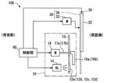
本発明の一実施形態における車両用表示装置は、図1に示すように、車両のインストルメントパネル2に搭載され、第1表示部10及び第2表示部20が協働して、視認側に対して表示を行なう。表示される情報としては、例えば車両の速度、エンジン回転数、燃料残量、エンジン冷却水の水温、あるいは電動モータの電流値等の車両の状態量、若しくは、例えば警報、道路情報、視界補助情報、電子メール等の各種情報が挙げられる。
As shown in FIG. 1, the display device for a vehicle in one embodiment of the present invention is mounted on an
車両用表示装置100が搭載されるインストルメントパネル2よりも車両上方には、車両のフロントウインドシールド3が設置されている。車両用表示装置100の視認者(例えば運転者)は、フロントウインドシールド3を通して道路及び道路標識等を含む前景を視認すると共に、前景からの視線移動によって車両用表示装置100を視認することとなる。
A vehicle front windshield 3 is installed above the
なお、本実施形態において車両上方とは、車両が平地を走行するとき又は平地に停止するときに、重力が生ずる方向とは反対側を示す。また、車両下方とは、重力が生ずる方向となる側を示す。 In the present embodiment, “above the vehicle” refers to the side opposite to the direction in which gravity occurs when the vehicle travels on a flat ground or stops on a flat ground. Further, the vehicle lower side indicates a side in which gravity is generated.
このような車両用表示装置100の構成を、図1〜6を用いて、以下に詳細に説明する。車両用表示装置100は、第1表示部10、第2表示部20、スライド機構30、通し窓40、遮光板50、及び制御部60を備えている。
The configuration of such a
第1表示部10は、図1,2に示すように、インストルメントパネル2中に位置し、表示板12、及び指針16a,16bを有している。表示板12は、一般的に文字板とも呼ばれており、例えば透光性樹脂の板状基材に透光性の印刷層又は遮光性の印刷層が形成された平板状を呈している。そして、透光性の印刷層が目盛及び文字の形状をなすことで、各指標12a,12b,12c,12dが形成されている。各指標12a〜dは、視認側とは反対側である背面側から指標用バックライト部14を用いて照明されることで、点灯表示されるようになっている。指標として、指針16aの周囲に、円周状の円周指標12a、及び部分円周状の部分指標12cが形成されている(図5も参照)。また、指針16bの周囲に、円周状の円周指標12b、及び部分円周状の部分指標12dが形成されている。そして各指標12a〜dは、制御部60より指標用バックライト部14を制御されて、それぞれ個別に点灯又は消灯の切り換えが可能となっている。
As shown in FIGS. 1 and 2, the
各指針16a〜bは、表示板12よりも視認側において配置される針状部材である。本実施形態の指針16a〜bは、互いに左右に並んで配置されている。表示板12より背面側に設けられ、制御部60により制御される指針用ステッピングモータ18の駆動により、各指針16a〜bは、表示板12を貫通して設けられる回転軸17a,17bの周りに回動するようになっている。各指針16a〜bの先端が点灯表示された指標12a〜dを指示することにより、第1表示部10は、視認側に対して表示を行なうことが可能となっている。
Each of the
特に本実施形態では、指針16aが点灯する円周指標12aを指示することで車両の速度が表示され、指針16aが点灯する部分指標12cを指示することで燃料残量が表示されるようになっている。また、指針16bが点灯する円周指標12bを指示することでエンジン回転数が表示され、指針16bが点灯する部分指標12dを指示することでエンジン冷却水の水温が表示されるようになっている。
In particular, in this embodiment, the speed of the vehicle is displayed by instructing the
第2表示部20は、第1表示部10よりも視認側に位置している。第2表示部20は、表示面22に画像を表示させる画像表示パネルとしての液晶パネルを主体に形成されている。特に本実施形態では、第2表示部20として、薄膜トランジスタ(Thin Film Transistor、TFT)を用い、2次元方向に配列された複数の液晶画素から形成されるアクティブマトリクス型の液晶パネルが採用されている。制御部60からの信号により、内臓バックライトからの光の透過率が液晶画素毎に制御されることで、第2表示部20は、視認側を向く表示面22に画像を形成可能となっている。このようにして形成された画像の光が視認側に透過することで、第2表示部20は、視認側に対して表示を行なうことが可能となっている。
The
スライド機構30は、第2表示部20をスライドさせる機構である。一例として図2に示すスライド機構30は、スライド用ステッピングモータ32、及び第2表示部20の側面ないしは背面に目立たないように取り付けられたレール部36を主体として構成されている。そして、制御部60により制御されたスライド用ステッピングモータ32の駆動により、レール部36の延伸方向に第2表示部20が相対移動する。このようにして、第2表示部20は、スライドするようになっている。なお、スライド機構30としては、本実施形態の構成に限らず、同様の作用が得られる様々な形態の機構を採用可能である。
The
なお、図2は、概略的な構成を示すものであり、各要素の形状及び位置関係を厳密に示すものではない。 Note that FIG. 2 shows a schematic configuration and does not strictly show the shape and positional relationship of each element.
スライド機構30が第2表示部20をスライドさせると、図3に示すように、第2表示部20の姿勢の変化に応じて、第1表示部10と第2表示部20との重なり面積SLが変化するようになっている。これにより、第1表示部10と第2表示部20とが共同で形成する表示面積SDは、重なり面積SLが大きい程小さくなり、また、重なり面積SLが小さい程大きくなる。より詳細には、第1表示部10に対して、第2表示部20が車両上方にスライドすると重なり面積SLが減少すると共に、表示面積SDが増大する。第2表示部20が車両下方にスライドすると重なり面積SLが増大すると共に、表示面積SDが減少する。
When the
本実施形態の第2表示部20は、制御部60によるスライド機構30の制御により、重複姿勢P1、ずれ姿勢P2、及び中間姿勢P3をとることが可能となっている。図4に示す重複姿勢P1は、第1表示部10との重なり面積SLが最大となる姿勢である。特に本実施形態では、重複姿勢P1における第2表示部20は、第1表示部10の全体と重なることで、第1表示部10を視認側から覆い隠す状態となる。したがって、第2表示部20が重複姿勢P1をとる場合では、第1表示部10は隠れて視認されず、第2表示部20の表示のみが透明板70を通じて視認可能となる。
The
図5に示すずれ姿勢P2は、第1表示部10との重なり面積SLが最小となる姿勢である。特に本実施形態では、ずれ姿勢P2における第2表示部20は、その下端部を第1表示部10の上端部と僅かに重ねる程度である。したがって、第2表示部20がずれ姿勢P2をとる場合では、第1表示部10は第2表示部20に隠されることなく露出した状態で、透明板70を通じて視認側から視認可能となる。これと共に第2表示部20は、第1表示部10よりも車両上方、すなわちインストルメントパネル2からフロントウインドシールド3側に張り出した位置において、視認側から視認可能となる。
5 is a posture in which the overlapping area SL with the
図1に示す中間姿勢P3は、第1表示部10との重なり面積SLが重複姿勢P1とずれ姿勢P2との間となる姿勢である。特に本実施形態では、中間姿勢P3における第2表示部20は、第1表示部10の面積の半分程度と重なることで、第1表示部10の上半分を視認側から覆い隠す状態となる。したがって、第2表示部20が中間姿勢P3をとる場合では、第1表示部10の上半分は隠れて視認されず、部分指標12c〜dが形成されている下半分は露出した状態で、透明板70を通じて視認側から視認可能となる。これと共に第2表示部20は、第1表示部10の露出する箇所PBよりも車両上方となる位置において、視認側から視認可能となる。
The intermediate posture P3 shown in FIG. 1 is a posture in which the overlapping area SL with the
通し窓40は、図1,4,5に示すように、第1表示部10の上端部の高さにおいて、第1表示部10よりも視認側に隣接して形成されている。通し窓40は、第2表示部20の形状に合わせた細長い形状であり、スライドする第2表示部20を通すことが可能となっている。
As shown in FIGS. 1, 4, and 5, the through
遮光板50は、通し窓40から視認側に向かって延伸する板状に形成されており、車両の外部からフロントウインドシールド3等を通じて入射する外光を遮光するようになっている。本実施形態の遮光板50は、インストルメントパネル2と質感を合わせるため、例えば合成樹脂からなる板状基材にレザーを貼り合わせて形成されている。
The
このような遮光板50により、中間姿勢P3をとる第2表示部20では、遮光板50を挟んで2分割されたような表示演出が可能となっている。
With such a
図2に示す制御部60は、CPU及びメモリ等からなる電子回路を主体として構成されている。CPUは、メモリに記憶されているコンピュータプログラムを実行することで、各種処理を実施可能となっている。
The
制御部60は、車両のECUと通信可能となっており、表示すべき情報が当該ECUから信号として入力される。あるいは、制御部60が各種センサと通信し、各種センサから信号として入力される情報を、制御部60にて表示すべきか否か選り分けるようにしてもよい。
The
また、制御部60は、第1表示部10、第2表示部20、及びスライド機構30と電気的に接続されており、上述のように、第1表示部10に表示される情報、第2表示部20に表示される情報、及び第2表示部20の姿勢を制御するようになっている。なお本実施形態では、車両のエンジンスイッチがオフされた状態では、制御部60は、第2表示部20が重複姿勢P1をとるように制御する。
The
次に、本実施形態における車両用表示装置100の制御部60が、コンピュータプログラムの実行により実施するフローチャートを、図6を用いて以下に説明する。本フローチャートの処理は、例えば設定時間毎に実施される。
Next, a flowchart executed by the
まず、ステップS10では、車両の速度が設定速度以上であるか否かを判定する。設定速度は、例えば80km/hに設定される。ステップS10にて肯定判定を下すと、ステップS34に移る。ステップS10にて否定判定を下すと、ステップS20に移る。 First, in step S10, it is determined whether or not the vehicle speed is equal to or higher than a set speed. The set speed is set to 80 km / h, for example. If an affirmation judging is made at Step S10, it will move to Step S34. If a negative determination is made in step S10, the process proceeds to step S20.
ステップS20では、表示すべき情報が設定情報量以上であるか否かを判定する。情報量は、例えば、表示すべき情報をビット換算したものであってもよく、表示すべき車両の状態量の種数であってもよく、あるいは、これらに情報の重要性又は表示に必要な面積等を重み付けして算出されたものであってもよい。ステップS20にて肯定判定を下すと、ステップS32に移る。ステップS20にて否定判定を下すと、ステップS30に移る。 In step S20, it is determined whether or not the information to be displayed is greater than or equal to the set information amount. The information amount may be, for example, a bit-converted amount of information to be displayed, may be a genus of state quantities of the vehicle to be displayed, or may be necessary for the importance or display of information. It may be calculated by weighting the area or the like. If an affirmation judging is made at Step S20, it will move to Step S32. If a negative judging is made at Step S20, it will move to Step S30.
車両の速度が設定速度未満の場合であって、表示すべき情報が設定情報量未満の場合のステップS30では、重複姿勢P1をとるように、第2表示部20をスライドする。ステップS30を以って一連の処理を終了する。
In step S30 when the vehicle speed is less than the set speed and the information to be displayed is less than the set information amount, the
車両の速度が設定速度未満の場合であって、表示すべき情報が設定情報量以上の場合のステップS32では、ずれ姿勢P2をとるように、第2表示部20をスライドする。ステップS32を以って一連の処理を終了する。
In the case where the speed of the vehicle is less than the set speed and the information to be displayed is equal to or larger than the set information amount, the
車両の速度が設定速度以上の場合のステップS34では、中間姿勢P3をとるように、第2表示部20をスライドする。ステップS34を以って一連の処理を終了する。
In step S34 when the speed of the vehicle is equal to or higher than the set speed, the
ここで、第2表示部20が各姿勢P1,P2,P3をとる場合の表示に関してそれぞれ詳細に説明する。
Here, the display when the
第2表示部20が重複姿勢P1をとる場合の第1表示部10は、前述のとおり、第2表示部20に覆い隠されているので、全ての指標12a〜dを消灯し、視認側への表示を行なわない。
Since the
第2表示部20が重複姿勢P1をとる場合の第2表示部20は、図4に示すように、表示すべき情報として、車両の速度及び燃料残量等を表示する。
As shown in FIG. 4, the
第2表示部20がずれ姿勢P2をとる場合の第1表示部10では、表示板12において部分指標12c〜dは消灯し、円周指標12a〜bは点灯した状態となる。円周指標12a〜bを各指針16a〜bがそれぞれ指示することで、第1表示部10は、情報としての車両の速度及びエンジン回転数を表示する。
In the
第2表示部20がずれ姿勢P2をとる場合の第2表示部20は、図5に示すように、表示すべき情報として、車両の速度及び道路のナビゲーション情報を表示する。
As shown in FIG. 5, the
第2表示部20が中間姿勢P3をとる場合の第1表示部10では、表示板12において円周指標12a〜bは消灯し、部分指標12c〜dは点灯した状態となる。そして各指針16a〜bは、表示板12のうち、第2表示部20と重なっておらず露出する箇所PBを、指示するように制御される。すわなち、露出する箇所PBにおいて点灯している部分指標12c〜dを各指針16a〜bがそれぞれ指示することで、第1表示部10は、情報としての燃料残量及びエンジン冷却水の水温を表示するようになっている。
In the
第2表示部20が中間姿勢P3をとる場合の第2表示部20は、図1に示すように、遮光板50を挟んで分割された箇所のうち、インストルメントパネル2からフロントウインドシールド3側に張り出す箇所POにおいて、高速運転中に最も重要となる情報として車両の速度を表示する。また第2表示部20は、分割された箇所のうち、第1表示部10と重なった箇所において、表示すべき情報のうち、張り出す箇所POにも第1表示部10の露出する箇所PBにも表示しきれなかった情報を表示する。換言すると、表示すべき情報の情報量が少なく、張り出す箇所PO及び第1表示部10の露出する箇所PBを以って全て表示できた場合は、図1のように、第1表示部と重なる箇所PLに何も表示する必要はない。
As shown in FIG. 1, the
(作用効果)
以上説明した本実施形態の作用効果を以下に説明する。
(Function and effect)
The operational effects of the present embodiment described above will be described below.
本実施形態によると、スライド機構30が第2表示部20をスライドさせる。これにより、第1表示部10と、第1表示部10よりも視認側に位置する第2表示部20との重なり面積SLが変化する。重なり面積SLの変化によれば、第1表示部10及び第2表示部20が視認側に対して行う表示面積SDを変化させることができる。例えば、重なり面積SLが大きくなる結果、表示面積SDが小さくなっている状態では、表示できる情報量は限られるが、当該表示面積SD内での視線移動負荷は軽減される。また例えば、重なり面積SLが小さくなる結果、表示面積SDが大きくなっている状態では、当該表示面積SD内での視線移動負荷は増大するが、表示できる情報量は多くなる。このため、視認者の好みや状況等に応じて、情報量と視線移動負荷とのバランスを変えることができるようになるので、視認性の高い車両用表示装置100を提供することができる。
According to the present embodiment, the
また、本実施形態によると、第1表示部10は、車両のインストルメントパネル2に位置し、スライド機構30は、車両上方に第1表示部10に対して第2表示部20をスライドさせることにより、重なり面積SLを減少させる。第2表示部20が車両上方にスライドすることにより、車両運転中に前景と第2表示部20との間の視線移動負荷を軽減することが可能となるので、視認性を高めることができる。
Moreover, according to this embodiment, the
また、本実施形態によると、第2表示部20は、重なり面積SLが最大となる重複姿勢P1と、重なり面積SLが最小となるずれ姿勢P2と、重なり面積SLが重複姿勢P1とずれ姿勢P2との間となる中間姿勢P3とをとる。このような中間姿勢P3により、視認者の好みや状況等に応じて、情報量と視線移動負荷とのバランスを多段階に変えることができるようになるので、視認性を高めることができる。
Further, according to the present embodiment, the
また、車両の速度が速い場合では、前景から視線を離し難くなるため、一見すると第2表示部20がずれ姿勢P2をとるのが良いと思われるが、第1表示部10及び第2表示部20の表示面積SDが最大となってしまうため、当該表示面積SD内での視線移動負荷が過大となってしまう。そこで本実施形態では、車両の速度が設定速度以上の場合、各姿勢P1,P2,P3のうち、中間姿勢P3をとる。このようにすることで、表示面積SD内での視線移動負荷を抑制しつつ、前景と第2表示部20との間の視線移動負荷を軽減することが可能となるので、視認性を高めることができる。
In addition, when the vehicle speed is high, it is difficult to separate the line of sight from the foreground. Therefore, the
また、本実施形態によると、第2表示部20は、車両の速度が設定速度未満の場合であって、表示すべき情報が所定情報量以上である場合、各姿勢P1,P2,P3のうち、ずれ姿勢P2をとる。ずれ姿勢P2をとることにより、所定情報量以上の表示すべき情報を大きな表示面積SDを生かして表示することが可能となるので、視認性を高めることができる。
Further, according to the present embodiment, the
また、本実施形態によると、第2表示部20は、車両の速度が設定速度未満の場合であって、表示すべき情報が所定情報量未満である場合、各姿勢P1,P2,P3のうち、重複姿勢P1をとる。重複姿勢P1をとることにより、所定情報量未満の表示すべき情報を小さな表示面積SDに集約して表示することが可能となるので、視認性を高めることができる。
In addition, according to the present embodiment, the
また、第1表示部10は、回動する指針16a〜bが表示板12の指標12a〜bを指示することにより表示を行なうものである場合、第1表示部10よりも視認側に位置する第2表示部20との重なりによって、第1表示部10の表示が機能しなくなることが懸念される。そこで本実施形態では、第2表示部20が中間姿勢P3をとる場合の指針16a〜bは、第2表示部20と重なっておらず視認側に露出する箇所PBを指示する。このような指針16a〜bの指示により、第1表示部10が第2表示部20と一部重なっていても、露出する箇所PBを有効活用して表示を行なうことができるので、情報量と視線移動負荷とのバランスを多段階に変えながら、視認性の高い車両用表示装置100を提供することができる。
The
(他の実施形態)
以上、本発明の一実施形態について説明したが、本発明は、当該実施形態に限定して解釈されるものではなく、本発明の要旨を逸脱しない範囲内において種々の実施形態に適用することができる。
(Other embodiments)
Although one embodiment of the present invention has been described above, the present invention is not construed as being limited to the embodiment, and can be applied to various embodiments without departing from the gist of the present invention. it can.
具体的に、変形例1としては、車両用表示装置100は、第2表示部20が重複姿勢P1をとる場合に、通し窓40を塞ぐ蓋942を備えていてもよい。図7の例では、第2表示部20が重複姿勢P1から中間姿勢P3又はずれ姿勢P2にスライドするときに、スライド機構30と連動して、蓋942が遮光板50と重なる位置に移動するようになっている。これによれば、通し窓40を通して装置100の内部に埃等の異物が侵入し、当該異物が表示の視認を阻害することを抑制できる。したがって、視認性が向上する。その他、異物対策として、異物を吸引する機構を設けてもよい。
Specifically, as a first modification, the
変形例2としては、第2表示部20が各姿勢P1,P2,P3をとる場合に、第1表示部10及び第2表示部20が表示する情報は、前述の内容に限られない。例えば、中間姿勢P3をとる場合、第2表示部20において燃料残量等の表示が行なわれ、第1表示部10において車両の速度等の表示が行われてもよい。
As a second modification, the information displayed by the
変形例3としては、第2表示部20の姿勢は、視認者の操作によって手動で切り替わるようにしてもよい。
As a third modification, the posture of the
変形例4としては、第2表示部20は、重複姿勢P1及びずれ姿勢P2の2つの姿勢をとるようにしてもよい。あるいは、第2表示部20は、複数の中間姿勢P3を含む4つ以上の姿勢をとるようにしてもよい。
As a fourth modification, the
変形例5としては、遮光板50は、設けられていなくてもよい。
As a fifth modification, the
変形例6としては、第1表示部10として、第2表示部20と同様に、画像表示パネルとしての液晶パネルが採用されていてもよい。
As a sixth modification, a liquid crystal panel as an image display panel may be employed as the
変形例7としては、第2表示部20の画像表示パネルとして、重なる箇所PLにおいて第1表示部10の表示やフロントウインドシールド3を通して見える前景を視認側に透過可能な、透過型有機ELパネルが採用されていてもよい。
As a modified example 7, as the image display panel of the
変形例8としては、第1表示部10の表示板12の位置に、表示板12の代わりにバックライトを設置する。加えて、第2表示部20は、当該バックライトの光を視認側に透過率を制御しつつ透過可能な複数の液晶画素を備えた構成としてもよい。これによれば、第2表示部20は、第1表示部10と重なる箇所の液晶画素の透過率を高くすることで、第1表示部10の指針16a〜bの影を、第2表示部20に映し出す表示演出が可能となる。
As a modified example 8, instead of the
100 車両用表示装置、2 インストルメントパネル、10 第1表示部、12 表示板、12a〜d 指標、16a〜b 指針、20 第2表示部、30 スライド機構、SD 表示面積、P1 重複姿勢、P2 ずれ姿勢、P3 中間姿勢、PB 露出する箇所
DESCRIPTION OF
Claims (8)
前記車両のインストルメントパネル(2)の内部に位置し、視認側に対して表示を行なう第1表示部(10)と、
前記第1表示部よりも視認側に位置し、視認側に対して表示を行なう第2表示部(20)と、
前記第2表示部をスライドさせることにより、前記第1表示部と前記第2表示部との重なり面積(SL)を変化させるスライド機構(30)とを備え、
前記第2表示部は、前記重なり面積が最小となるずれ姿勢(P2)をとる場合に、前記インストルメントパネルよりも車両上方に張り出すように構成されることを特徴とする車両用表示装置。 Mounted on the vehicle,
A first display section (10) that is located inside the instrument panel (2) of the vehicle and that displays on the viewing side;
A second display unit (20) that is positioned on the viewer side of the first display unit and displays on the viewer side;
A slide mechanism (30) that changes an overlapping area (SL) between the first display unit and the second display unit by sliding the second display unit ;
The second display portion, the overlap when the area takes a shift position (P2) that minimizes than said instrument panel is configured to protrude upward of the vehicle display device for a vehicle according to claim Rukoto.
前記重なり面積が最大となる重複姿勢(P1)と、
前記ずれ姿勢と、
前記重なり面積が前記重複姿勢と前記ずれ姿勢との間となる中間姿勢(P3)とをとることを特徴とする請求項1又は2に記載の車両用表示装置。 The second display unit
An overlapping posture (P1) that maximizes the overlapping area;
And the attitude Re not a pre-Symbol,
The vehicle display device according to claim 1 or 2, wherein the overlapping area takes an intermediate posture (P3) between the overlapping posture and the shifted posture.
前記重なり面積が最大となる重複姿勢と、
前記ずれ姿勢と、
前記重なり面積が前記重複姿勢と前記ずれ姿勢との間となる中間姿勢とをとり、
前記車両の速度が設定速度以上の場合、前記各姿勢のうち、前記中間姿勢をとることを特徴とする請求項2に記載の車両用表示装置。 The second display unit
An overlapping posture in which the overlapping area is maximized;
And the attitude Re not a pre-Symbol,
Taking an intermediate posture where the overlapping area is between the overlapping posture and the shifted posture,
The vehicle display device according to claim 2, wherein, when the speed of the vehicle is equal to or higher than a set speed, the intermediate posture is taken out of the postures.
前記第2表示部が前記中間姿勢をとる場合の前記指針は、前記表示板のうち、前記第2表示部と重なっておらず視認側に露出する箇所(PB)を、指示するように制御されることを特徴とする請求項3から6のいずれか1項に記載の車両用表示装置。 The first display unit performs display when a rotating pointer (16a-b) indicates an indicator (12a-d) of the display board (12),
The pointer when the second display unit assumes the intermediate posture is controlled to indicate a position (PB) of the display plate that does not overlap the second display unit and is exposed to the viewer side. The vehicular display device according to any one of claims 3 to 6, wherein
視認側に対して表示を行なう第1表示部(10)と、
前記第1表示部よりも視認側に位置し、視認側に対して表示を行なう第2表示部(20)と、
前記第2表示部をスライドさせることにより、前記第1表示部と前記第2表示部との重なり面積(SL)を変化させるスライド機構(30)とを備え、
前記第2表示部は、
前記重なり面積が最大となる重複姿勢(P1)と、
前記重なり面積が最小となるずれ姿勢(P2)と、
前記重なり面積が前記重複姿勢と前記ずれ姿勢との間となる中間姿勢(P3)とをとり、
前記第1表示部は、回動する指針(16a〜b)が表示板(12)の指標(12a〜d)を指示することにより表示を行なうものであり、
前記第2表示部が前記中間姿勢をとる場合の前記指針は、前記表示板のうち、前記第2表示部と重なっておらず視認側に露出する箇所(PB)を、指示するように制御されることを特徴とする車両用表示装置。 Mounted on the vehicle,
A first display (10) for displaying on the viewer side;
A second display unit (20) that is positioned on the viewer side of the first display unit and displays on the viewer side;
A slide mechanism (30) that changes an overlapping area (SL) between the first display unit and the second display unit by sliding the second display unit ;
The second display unit
An overlapping posture (P1) that maximizes the overlapping area;
A displacement posture (P2) that minimizes the overlapping area;
An intermediate posture (P3) in which the overlapping area is between the overlapping posture and the displaced posture;
The first display unit performs display when a rotating pointer (16a-b) indicates an indicator (12a-d) of the display board (12),
The pointer when the second display unit assumes the intermediate posture is controlled to indicate a position (PB) of the display plate that does not overlap the second display unit and is exposed to the viewer side. A vehicle display device.
Priority Applications (1)
| Application Number | Priority Date | Filing Date | Title |
|---|---|---|---|
| JP2015034461A JP6432387B2 (en) | 2015-02-24 | 2015-02-24 | Vehicle display device |
Applications Claiming Priority (1)
| Application Number | Priority Date | Filing Date | Title |
|---|---|---|---|
| JP2015034461A JP6432387B2 (en) | 2015-02-24 | 2015-02-24 | Vehicle display device |
Publications (2)
| Publication Number | Publication Date |
|---|---|
| JP2016155458A JP2016155458A (en) | 2016-09-01 |
| JP6432387B2 true JP6432387B2 (en) | 2018-12-05 |
Family
ID=56824789
Family Applications (1)
| Application Number | Title | Priority Date | Filing Date |
|---|---|---|---|
| JP2015034461A Expired - Fee Related JP6432387B2 (en) | 2015-02-24 | 2015-02-24 | Vehicle display device |
Country Status (1)
| Country | Link |
|---|---|
| JP (1) | JP6432387B2 (en) |
Families Citing this family (1)
| Publication number | Priority date | Publication date | Assignee | Title |
|---|---|---|---|---|
| WO2018037605A1 (en) * | 2016-08-24 | 2018-03-01 | パイオニア株式会社 | Display device |
Family Cites Families (9)
| Publication number | Priority date | Publication date | Assignee | Title |
|---|---|---|---|---|
| DE10331131A1 (en) * | 2003-07-09 | 2005-01-27 | Borg Instruments Ag | instrument cluster |
| JP4418296B2 (en) * | 2004-05-19 | 2010-02-17 | 矢崎総業株式会社 | Compound display device |
| JP4244937B2 (en) * | 2005-01-24 | 2009-03-25 | 株式会社デンソー | Display device |
| JP2009204560A (en) * | 2008-02-29 | 2009-09-10 | Nippon Seiki Co Ltd | Vehicular display device |
| JP5127063B2 (en) * | 2009-02-16 | 2013-01-23 | 矢崎総業株式会社 | Display unit drive method for movable meter |
| JP5269643B2 (en) * | 2009-02-24 | 2013-08-21 | 矢崎総業株式会社 | Combination meter |
| JP5219893B2 (en) * | 2009-03-09 | 2013-06-26 | 矢崎総業株式会社 | Combination meter |
| JP5441252B2 (en) * | 2009-09-25 | 2014-03-12 | 矢崎総業株式会社 | Movable meter and display control method thereof |
| WO2014129197A1 (en) * | 2013-02-22 | 2014-08-28 | パナソニック株式会社 | Display control device and display control program |
-
2015
- 2015-02-24 JP JP2015034461A patent/JP6432387B2/en not_active Expired - Fee Related
Also Published As
| Publication number | Publication date |
|---|---|
| JP2016155458A (en) | 2016-09-01 |
Similar Documents
| Publication | Publication Date | Title |
|---|---|---|
| JP5323132B2 (en) | Vehicle instrument | |
| JP5336330B2 (en) | Display device | |
| US10953748B2 (en) | Multi-layer display for vehicle dash | |
| JP4761551B2 (en) | In-vehicle meter display device | |
| KR20060127213A (en) | Vehicle information display device and vehicle information display method | |
| JP5605155B2 (en) | Combined instrument for vehicles | |
| JP2012228973A (en) | Display device for vehicle | |
| JP5202861B2 (en) | Display device | |
| JP5160665B2 (en) | In-vehicle meter display device | |
| JP6432387B2 (en) | Vehicle display device | |
| JP5187575B2 (en) | Vehicle display device | |
| US10513182B2 (en) | Vehicle display apparatus | |
| JP5105312B2 (en) | Vehicle display device | |
| JP4244937B2 (en) | Display device | |
| JP2015215322A (en) | Vehicle-mounted meter | |
| JP4438538B2 (en) | Vehicle display device | |
| JP5995056B2 (en) | Vehicle display device | |
| JP2012113069A (en) | Display device | |
| JP6733182B2 (en) | Vehicle display device and display panel control method | |
| JP2016133422A (en) | Display device for vehicle | |
| JP2020083192A (en) | Vehicular meter unit | |
| JP6428431B2 (en) | Vehicle display device | |
| JP7283478B2 (en) | VEHICLE DISPLAY DEVICE, VEHICLE DISPLAY CONTROL METHOD, AND VEHICLE DISPLAY CONTROL PROGRAM | |
| JP6361548B2 (en) | Vehicle display device | |
| JP6394294B2 (en) | Vehicle display device |
Legal Events
| Date | Code | Title | Description |
|---|---|---|---|
| A621 | Written request for application examination |
Free format text: JAPANESE INTERMEDIATE CODE: A621 Effective date: 20170627 |
|
| A977 | Report on retrieval |
Free format text: JAPANESE INTERMEDIATE CODE: A971007 Effective date: 20180511 |
|
| A131 | Notification of reasons for refusal |
Free format text: JAPANESE INTERMEDIATE CODE: A131 Effective date: 20180522 |
|
| A521 | Request for written amendment filed |
Free format text: JAPANESE INTERMEDIATE CODE: A523 Effective date: 20180711 |
|
| TRDD | Decision of grant or rejection written | ||
| A01 | Written decision to grant a patent or to grant a registration (utility model) |
Free format text: JAPANESE INTERMEDIATE CODE: A01 Effective date: 20181009 |
|
| A61 | First payment of annual fees (during grant procedure) |
Free format text: JAPANESE INTERMEDIATE CODE: A61 Effective date: 20181022 |
|
| R151 | Written notification of patent or utility model registration |
Ref document number: 6432387 Country of ref document: JP Free format text: JAPANESE INTERMEDIATE CODE: R151 |
|
| R250 | Receipt of annual fees |
Free format text: JAPANESE INTERMEDIATE CODE: R250 |
|
| LAPS | Cancellation because of no payment of annual fees |