JP4244937B2 - Display device - Google Patents
Display device Download PDFInfo
- Publication number
- JP4244937B2 JP4244937B2 JP2005016062A JP2005016062A JP4244937B2 JP 4244937 B2 JP4244937 B2 JP 4244937B2 JP 2005016062 A JP2005016062 A JP 2005016062A JP 2005016062 A JP2005016062 A JP 2005016062A JP 4244937 B2 JP4244937 B2 JP 4244937B2
- Authority
- JP
- Japan
- Prior art keywords
- liquid crystal
- display
- crystal display
- unit
- display unit
- Prior art date
- Legal status (The legal status is an assumption and is not a legal conclusion. Google has not performed a legal analysis and makes no representation as to the accuracy of the status listed.)
- Expired - Fee Related
Links
- 239000004973 liquid crystal related substance Substances 0.000 claims description 100
- 230000033001 locomotion Effects 0.000 claims description 25
- 238000006243 chemical reaction Methods 0.000 claims description 8
- 230000005540 biological transmission Effects 0.000 description 8
- 230000000694 effects Effects 0.000 description 8
- 230000002542 deteriorative effect Effects 0.000 description 2
- 238000010586 diagram Methods 0.000 description 2
- 238000009792 diffusion process Methods 0.000 description 2
- 239000000446 fuel Substances 0.000 description 2
- 239000000853 adhesive Substances 0.000 description 1
- 230000001070 adhesive effect Effects 0.000 description 1
- 239000000498 cooling water Substances 0.000 description 1
- 238000001514 detection method Methods 0.000 description 1
- 230000007613 environmental effect Effects 0.000 description 1
- 239000000463 material Substances 0.000 description 1
- 239000011347 resin Substances 0.000 description 1
- 229920005989 resin Polymers 0.000 description 1
- 239000000758 substrate Substances 0.000 description 1
- 239000010409 thin film Substances 0.000 description 1
Images


Description
本発明は、表示領域の大きさが切り替わる表示手段を含め複数の表示手段を備える表示装置に関するものである。 The present invention relates to a display device including a plurality of display means including display means for switching the size of a display area.
近年、自動車を取り巻く環境変化に応じて、運転者へ提供される運転操作を補助する各種情報の種類及び量が急激に増加している。例えば、走行速度,走行距離及び任意区間距離,燃料残量,冷却水温度等の車両情報に加えて、現在位置や目的地点を地図上に表示するナビゲーション情報あるいは電波信号により送信される道路交通情報等である。 2. Description of the Related Art In recent years, the types and amounts of various types of information that assist driving operations provided to drivers are rapidly increasing in accordance with environmental changes surrounding automobiles. For example, in addition to vehicle information such as travel speed, travel distance and arbitrary section distance, fuel remaining amount, cooling water temperature, etc., road information transmitted by navigation information or radio signals that display the current position and destination point on a map Etc.
これらの多くの情報を当該自動車へ効率良く伝えることを目的として、例えば、液晶パネル等の画像表示可能な液晶表示ユニットと共にこの両側に文字板上を指針が回動して値を指示する指針駆動ユニットを一体に組み込んだ車両用計器が提案されている(特許文献1を参照)。
この種の車両用計器において、液晶表示ユニットが複数の情報を同時に表示する場合、液晶表示ユニットが大きくなり、この両側に指針駆動ユニットを設けるスペースが小さくなり、この車両用計器の見映えを悪化させる。 In this type of vehicle instrument, when the liquid crystal display unit displays a plurality of information at the same time, the liquid crystal display unit becomes larger, and the space for providing the pointer drive units on both sides of the liquid crystal display unit becomes smaller, which deteriorates the appearance of the vehicle instrument. Let
このため、液晶表示ユニットが複数の情報を切り替えて表示することが考えられるが、液晶表示ユニットが表示する情報の表示が小さい時、液晶表示ユニットの表示部にデッドスペースが生ずる。 For this reason, it is conceivable that the liquid crystal display unit switches and displays a plurality of information. However, when the information displayed by the liquid crystal display unit is small, a dead space occurs in the display unit of the liquid crystal display unit.
例えば、液晶表示ユニットがその表示部の全域で地図情報を表示する場合は、表示部にデッドスペースが生じないが、ギヤシフト情報(PRND2L)を表示する場合は、その表示が小さいため表示部にデッドスペースが生じる。 For example, when the liquid crystal display unit displays map information over the entire display unit, no dead space is generated in the display unit. However, when the gear shift information (PRND2L) is displayed, the display unit is dead because the display is small. Space is created.
このため、液晶表示ユニットが表示する情報の表示が小さい場合、両側の指針駆動ユニットに対して、この表示が間延びして見え、この車両用計器の見映えを悪化させる。 For this reason, when the display of the information displayed on the liquid crystal display unit is small, this display appears to be extended with respect to the pointer drive units on both sides, which deteriorates the appearance of the vehicle instrument.
このことは、車両用計器装置に限らず、表示領域の大きさが切り替わる表示手段を含め複数の表示手段を備える表示装置に共通する問題である。ここで、表示領域の大きさが切り替わるものには、上述の表示領域の大きさが異なる複数の情報を切り替えて表示するものに限らず、同一の情報を、その表示領域を大小で切り替えて表示するもの等も含む。 This is a problem common to not only the vehicle instrument device but also a display device including a plurality of display means including a display means in which the size of the display area is switched. Here, the display area size is not limited to the information displayed by switching a plurality of information having different display area sizes, and the same information is displayed with the display area switched between large and small. It includes those that do.
本発明は、上記点に鑑みてなされたものであり、表示領域の大きさが切り替わる表示手段を含め複数の表示手段を備える表示装置の見映えを向上させることを目的とする。 The present invention has been made in view of the above points, and an object of the present invention is to improve the appearance of a display device including a plurality of display means including a display means in which the size of a display area is switched.
本発明は上記目的を達成するため、以下の技術的手段を採用する。 In order to achieve the above object, the present invention employs the following technical means.
請求項1に記載の表示装置は、表示領域の大きさを切り替えることができる第1表示手段として、情報を表示する液晶パネルと液晶パネルを透過照明する光源とを有する液晶表示ユニットと、液晶表示ユニットの前面側に配設され、所望の情報を表示する第2表示手段として、文字盤と文字盤の前面に沿って回動する指針とを備える2つの指針駆動ユニットと、液晶表示ユニットと2つの指針駆動ユニットとを収容する計器筐体部と、計器筐体部に対して、2つの指針駆動ユニットを液晶表示ユニットの前面に沿って移動可能に取り付ける位置可変手段とを備え、
2つの指針駆動ユニットは、間に液晶表示ユニット配置させて隣接関係に配置されており、位置可変手段は、2つの指針駆動ユニットにより液晶表示ユニットが情報を表示しない領域の少なくとも一部が遮蔽され、かつ液晶表示ユニットの表示領域が遮蔽されないように、2つの指針駆動ユニットを移動させ、2つの指針駆動ユニットが互いに近寄ったり離れたりして連動することにより、液晶表示ユニットの表示領域が拡大、縮小するように設定されており、液晶表示ユニットの表示領域が拡大、縮小時において異なる表示を表示領域に表示する構成とする。
The display device according to
The two pointer driving units are arranged adjacent to each other with a liquid crystal display unit disposed therebetween, and the position variable means is configured to shield at least a part of the area where the liquid crystal display unit does not display information by the two pointer driving units. and so as not to be shielded display area of the liquid crystal display unit, moves the two hand drive unit, by two hands drive unit interlocked with and away from closer to each other, the display area of the liquid crystal display unit is enlarged, It is set so as to reduce the display area of the liquid crystal display unit is enlarged, a structure that displays a different display during reduction in the display area.
この構成では、指針駆動ユニットにより液晶表示ユニットの情報を表示しない領域の少なくとも一部を遮蔽させ、かつ液晶表示ユニットの表示を遮蔽させないように指針駆動ユニットを移動させる。これにより、液晶表示ユニットの表示が小さい場合、指針駆動ユニットに対して、この表示が間延びして見えることがなく、液晶表示ユニットの表示が大きい場合、この表示が指針駆動ユニットによって邪魔されることがない。 In this configuration, to shield at least a part of the region that does not display the information of the liquid crystal display unit by hand driving unit, and moves the pointer driving unit so as not to shield the display of the liquid crystal display unit. As a result, when the display of the liquid crystal display unit is small, the display does not appear to be extended to the pointer driving unit , and when the display of the liquid crystal display unit is large, the display is obstructed by the pointer driving unit . There is no.
即ち、液晶表示ユニットの大小様々な表示を、その見映えを悪化させることがなく、その見映えを向上させて行うことができる。その結果、表示領域の大きさを切り替えることができる液晶表示ユニットと指針駆動ユニットとを備える表示装置の見映えを向上させることできる。 That is, various sizes of the liquid crystal display unit can be displayed with improved appearance without deteriorating the appearance. As a result, it is possible to improve the appearance of a display device that includes a liquid crystal display unit that can switch the size of the display area and a pointer drive unit .
請求項2に記載の表示装置は、液晶表示ユニットが表示する情報に応じてその表示領域の大きさが切り替わるように構成される。 The display device according to claim 2 is configured such that the size of the display area is switched according to information displayed by the liquid crystal display unit .
この構成では、液晶表示ユニットが表示する情報に応じてその表示領域の大きさが切り替えるため、この構成においても、上述の効果を得ることができる。 In this configuration, the size of the display area is switched according to the information displayed on the liquid crystal display unit , and thus the above-described effect can be obtained even in this configuration.
請求項3に記載の表示装置は、指針駆動ユニットを液晶表示ユニットの表示領域の大きさの切り替えに連動させて移動させる制御手段を備える構成とする。 According to a third aspect of the present invention, the display device includes a control unit that moves the pointer driving unit in conjunction with the switching of the size of the display area of the liquid crystal display unit .
この構成では、指針駆動ユニットを液晶表示ユニットの表示領域の大きさの切り替えに連動させて移動させるため、上述の効果を自動制御として得ることができる。 In this configuration, since the pointer driving unit is moved in conjunction with the switching of the display area size of the liquid crystal display unit , the above-described effect can be obtained as automatic control.
請求項4に記載の表示装置は、位置可変手段が回転運動を直線運動に変換する動力変換手段と動力変換手段を回動させる駆動部とを有し、動力変換手段が駆動部の回動に応じて指針駆動ユニットを液晶表示ユニットの前面に沿って移動させる構成とする。 According to a fourth aspect of the present invention, there is provided a display device comprising: a power converting means for converting the rotational motion into a linear motion, and a driving section for rotating the power converting means; and the power converting means for rotating the driving section. Accordingly, the pointer driving unit is configured to move along the front surface of the liquid crystal display unit .
この構成では、位置可変手段が回転運動を直線運動に変換するものであるため、簡易な構成で上述の効果を得ることができる。 In this configuration, since the position variable means converts the rotational motion into a linear motion, the above-described effects can be obtained with a simple configuration.
請求項5に記載の表示装置は、外部からの指示信号を受けて、液晶表示ユニット、指針駆動ユニット、および位置可変手段を作動させ、指針駆動ユニットにより液晶表示ユニットが情報を表示しない領域の少なくとも一部が遮蔽され、かつ液晶表示ユニットの表示領域が遮蔽されないように、指針駆動ユニットを移動させる制御手段を備える構成とする。 The display device according to claim 5 receives an instruction signal from the outside, and operates the liquid crystal display unit, the pointer driving unit, and the position changing unit, and at least an area in which the liquid crystal display unit does not display information by the pointer driving unit. some are shielded, and as the display area of the liquid crystal display unit is not shielded, a configuration that Ru comprising a control means for moving the pointer driving unit.
この構成では、外部からの指示信号を受けて、制御手段が、指針駆動ユニットにより液晶表示ユニットの情報を表示しない領域の少なくとも一部を遮蔽させ、かつ液晶表示ユニットの表示を遮蔽させないように指針駆動ユニットを移動させる。これにより、外部からの指示信号をトリガーとして、請求項1の効果を得ることができる。
In this configuration, upon receiving an instruction signal from the external control means, guidance as the hand drive unit is shielded at least part of a region that does not display the information of the liquid crystal display unit, and does not shield the display of the liquid crystal display unit Move the drive unit . As a result, the effect of
請求項6に記載の表示装置は、制御手段が指示信号に応じて液晶表示ユニットが表示する情報を切り替えると共に情報に応じた表示領域の大きさに切り替える構成とする。 The display device according to claim 6 is configured such that the control unit switches information displayed on the liquid crystal display unit in accordance with the instruction signal and switches the display area to a size corresponding to the information.
この構成では、制御手段が液晶表示ユニットの表示する情報に応じてその表示領域の大きさを切り替える。これにより、この構成においても、請求項5の効果を得ることができる。 In this configuration, the control means switches the size of the display area according to the information displayed on the liquid crystal display unit . Thereby, also in this structure, the effect of Claim 5 can be acquired.
請求項7に記載の表示装置は、指示信号を発生する切替指示手段を備える構成とする。 According to a seventh aspect of the present invention, there is provided a display device comprising a switching instruction means for generating an instruction signal.
この構成では、指示信号を発生する切替指示手段を備え、これにより上述の効果を得ることができる。 In this configuration, switching instruction means for generating an instruction signal is provided, and thereby the above-described effects can be obtained.
請求項8に記載の表示装置は、切替指示手段が車両の走行状態に応じて変化する指示信号を発生する構成とする。 The display device according to claim 8 is configured such that the switching instruction means generates an instruction signal that changes in accordance with the traveling state of the vehicle.
この構成では、切替指示手段が車両の走行状態に応じて変化する指示信号を発生するため、指針駆動ユニットを車両の走行状態の切り替えに連動させて移動させることができる。この結果、上述の効果を車両の走行状態を切り替える際に自動的に得ることができる。 In this configuration, since the switching instruction means generates an instruction signal that changes according to the traveling state of the vehicle, the pointer drive unit can be moved in conjunction with the switching of the traveling state of the vehicle. As a result, the above-described effect can be automatically obtained when the traveling state of the vehicle is switched.
請求項9に記載の表示装置は、切替指示手段が表示領域の大きさの切替操作に連動して変化する指示信号を発生する構成とする。 The display device according to claim 9 is configured such that the switching instruction means generates an instruction signal that changes in conjunction with a switching operation of the size of the display area.
この構成では、切替指示手段が表示領域の大きさの切替操作に連動して変化する指示信号を発生するため、指針駆動ユニットを液晶表示ユニットの表示領域の大きさの切替えに連動させて移動させることができる。この結果、上述の効果を表示領域の大きさの切替操作を行う際に自動的に得ることができる。 In this configuration, since the switching instruction means generates an instruction signal that changes in conjunction with the switching operation of the display area size, the pointer drive unit is moved in conjunction with the switching of the display area size of the liquid crystal display unit . be able to. As a result, the above-described effects can be automatically obtained when the display area size switching operation is performed.
以下、本発明による表示装置を、自動車に搭載されるコンビネーションメータ1に適用した場合を例に図面に基づいて説明する。
Hereinafter, a case where the display device according to the present invention is applied to a
(構成)
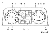
図1は、本発明の一実施形態による表示装置であるコンビネーションメータ1の正面図である。図1の矢印が示す上下方向が自動車の上下方向と同じである。
(Constitution)
FIG. 1 is a front view of a
図2は、図1中のII−II線断面図である。 2 is a cross-sectional view taken along line II-II in FIG.
図3は、図1中のIII−III線断面図である。 3 is a cross-sectional view taken along line III-III in FIG.
図4は、第2表示手段である車速計10と回転計20とが最も離れた状態を示す図1に示すコンビネーションメータ1の正面図である。
FIG. 4 is a front view of the
図5は、車速計10と回転計20とが最も近づいた状態を示す図1に示すコンビネーションメータ1の正面図である。
FIG. 5 is a front view of the
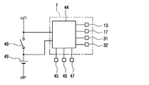
図6は、図1に示すコンビネーションメータ1の電気回路構成を説明する回路構成図である。
FIG. 6 is a circuit configuration diagram illustrating an electrical circuit configuration of the
表示装置であるコンビネーションメータ1は、自動車の運転席前方に配置されて当該自動車に関する各種車両情報を表示する。本実施形態によるコンビネーションメータ1は、図1に示すように、図中の矢印が示す左側に第2表示手段である速度計10と、図中の矢印が示す右側に第2表示手段である回転計20と、それらの間に第1表示手段である液晶表示器30とを備える。
The
速度計10は、自動車の走行速度を表示するもので、回転計20は、エンジン回転数を表示するもので、液晶表示器30は、ナビゲーション情報や道路交通情報等を表示するものである。
The
速度計10と回転計20は、それぞれ、文字盤11、21と、指針12、22と、可動筐体15、25とを備える。文字盤11、21は、それぞれ、可動筐体15、25に対して固定され、指針12、22は、それぞれ、文字盤11、21の前面(図2の矢印が示す上側の面)に沿って回動する。可動筐体15、25は、それぞれ、計器筐体部の一部を構成する意匠板41に対して図1の矢印が示す左右方向に移動可能に取り付けられる。
The
各文字盤11,21の表面(図2の矢印が示す上側の面)あるいは裏面(図2の矢印が示す下側の面)には、目盛や文字等が、印刷あるいはホットスタンプ等を施すことにより形成される。
Scales, letters, etc. are printed or hot stamped on the front surface (upper surface indicated by the arrow in FIG. 2) or back surface (lower surface indicated by the arrow in FIG. 2) of each
以下、速度計10の構成について詳細に説明する。文字盤11には、図2に示すように、後述するムーブメント13のシャフト13aを挿通させるための貫通孔が設けられ、文字盤2の背後(図2の矢印が示す下側)には、プリント基板14が配置される。プリント基板14は、速度計10の電気回路部を構成するものであり、可動筐体15に固定される。ムーブメント13は、プリント基板14に実装される。
Hereinafter, the configuration of the
ムーブメント13は、例えば交差コイル式アクチュエータ、あるいはステッピングモータ等から構成され、外部からの電気信号(本実施形態においては車速に関する信号)に対応した角度だけシャフト13aを回動させるものである。シャフト13aは、文字盤2の貫通孔を通して表面側(図2の矢印が示す上側)へ延出し、その先端に指針12が固定される。
The
位置可変手段の一部を構成する駆動部材16は、可動筐体15を、左右方向(図1と図2の矢印が示す左右方向)に、移動させるのものであり、取付部16aとガイド部16bと動力変換手段の一部を構成するスライドギア部16cとから構成される。
The
可動筐体15には取付穴15aが設けられ、意匠板41にはスライド穴41aが設けられる。スライド穴41aは、図2と図3で示すように、略長方形を有する。駆動部材16の取付部16aを、意匠板41にはスライド穴41aを通して、図3に示すように可動筐体15の底面と駆動部材16のガイド部16bとで意匠板41を挟むようにして、可動筐体15に対して取付穴15aの位置で固定する。
The
尚、可動筐体15と駆動部材16と意匠板41は、それぞれ、樹脂材料で形成され、駆動部材16の取付部16aは、可動筐体15に対して取付穴15aの位置で接着剤等により固定される。これにより、可動筐体15は、意匠板41に対して、図3の矢印が示す左右方向に拘束され、かつ図2の矢印が示す左右方向に移動可能に取り付けられる。
The
具体的には、駆動部材16の取付部16aとガイド部16bとの間の部分が、意匠板41のスライド穴41aに配置され、この部分が、意匠板41に対して、スライド穴41aの長手方向(図2の矢印が示す左右方向)に移動可能に構成される。
Specifically, a portion between the mounting
尚、駆動部材16のスライドギア部16cは、可動筐体15が意匠板41に対して図2の矢印が示す左方向へ最大限移動した場合に、後述する液晶表示器30の液晶パネル31や図示しない光拡散板と干渉しない位置に形成される。
Note that the
駆動部材16の図2と図3の矢印が示す下側には、駆動部の一部を構成するシャフト17aを、その長手方向を回転軸として回動させる駆動部の一部を構成するムーブメント17が配置される。ムーブメント17は、プリント基板18に実装固定される。シャフト17aは、プリント基板18の貫通孔を通して図中の矢印が示す上側へ延出し、その先端には動力変換手段の一部を構成する回転ギア17bが固定される。
2 and 3 below the
ムーブメント17は、ムーブメント13に比較して大型(高トルク対応タイプ)である点以外は、同じである。プリント基板18は、計器筐体部の一部を構成するケース42に固定される。回転ギア17bと駆動部材16のスライドギア部16cは、それぞれ図示しない歯を備え、図2と図3に示すようにかみ合うように配設される。
The
即ち、本実施形態では、位置可変手段は、駆動部材16とムーブメント17とシャフト17aと回転ギア17bとから構成され、動力変換手段は、回転ギア17bと駆動部材16のスライドギア部16cとから構成される。また、駆動部は、ムーブメント17とシャフト17aとから構成される。
That is, in this embodiment, the position variable means is constituted by the
図2において、プリント基板14とプリント基板18とは、可撓性を有するフレキシブル配線14aによって、接続される。
In FIG. 2, the printed
尚、意匠板41のスライド穴41aは、可動筐体15が図2の右側へ最大限移動した場合に、フレキシブル配線14aが駆動部材16と意匠板41とにより挟まることがないように、形成される。具体的には、スライド穴41aは、長手方向(図2の矢印が示す左右方向)の右側で右方向へ大きく設けられている。
The
プリント基板18には、マイクロコンピュータ等から構成された制御手段である制御装置44(図6)が実装される。制御装置44は、入力される外部からの電気信号に応じてムーブメント13、ムーブメント17、液晶パネル31、発光ダイオード32等を制御するものである。
On the printed
回転計20の構成は、速度計10の構成と同様なため、その説明を省略する。
Since the configuration of the
液晶表示器30は、意匠板41の背後(図2の矢印が示す下側)に配設された液晶パネル31と、液晶パネル31の背後(図2の矢印が示す下側)に配設された光源である発光ダイオード32と、これらの間に配設された図示しない光拡散板とを備える。発光ダイオード32は、液晶パネル31を透過照明するものであり、光拡散板は、発光ダイオード32の光を均一に液晶パネル31の裏面(図2の矢印が示す下側の面)導くものである。
The
液晶パネル31は、TFT(Thin Film Transistor)型液晶パネルであり、その表示が意匠板41に設けられた開口部41bを通して目視側(図2の矢印が示す上側)より視認されるように、配設される。即ち、液晶パネル31は、速度計10の可動筐体15と回転計20の可動筐体25との背後(図2と図3との矢印が示す下側)に配設される。
The
液晶パネル31は、図4において、意匠板41の開口部41bを通しその略全域を表示領域31aとし、地図情報を表示する。マーク31bは、表示領域31a内で表示される地図情報において当該自動車の位置を示すものである。この時、速度計10と回転計20とは、それぞれ、図中の矢印が示す左方向と右方向とへ移動し、互いに最も離れた状態に制御されるように構成される。
In FIG. 4, the
また、液晶パネル31は、図5においては、意匠板41の開口部41bを通して、その一部の領域を表示領域31aとし、ギアシフト情報(トランスミッションのギアポジション)を表示する。マーク31bは、表示領域31a内においてトランスミッションのギアが切り替えられたポジションを示すものである。
In FIG. 5, the
図5において、マーク31bは、トランスミッションのギアがパーキングポジションに切り替えられていることを示す。この場合、マーク31bは、例えば、赤色を背景に黒色の文字「P」で表示され、他の文字「R、N、D、2、L」は、白色を背景に黒色で表示される。この時、速度計10と回転計20とは、それぞれ、図中の矢印が示す右方向と左方向とへ移動し、互いに最も近づいた状態に制御されるように構成される。
In FIG. 5, the
以上説明した本実施形態によるコンビネーションメータ1の電気回路構成について、図6に基づいて説明する。
The electric circuit configuration of the
制御装置44には、常時バッテリ49から電力が供給され、切替指示手段でもあるイグニッションスイッチ48がその操作ポジション(オフポジション、オンポジション)を検出可能に接続され、当該自動車の車速を検出する車速センサ45、当該自動車のエンジン回転数を検出する回転センサ46、トランスミッションのギアポジションを検出する切替指示手段であるギアポジションセンサ47、図示しないセンサやスイッチ等がそれらの信号を入力可能に接続される。
The
また、これらの各種センサ45,46,47からの検出信号に応じて制御装置44により駆動されるデバイスが接続されている。すなわち、ムーブメント13、17、液晶パネル31、発光ダイオード32等が、制御装置44に接続されている。
In addition, devices driven by the
尚、図1は、速度計10と回転計20とが図4と図5との中間位置である状態を示す。この時、イグニッションスイッチ48は、オンされる前、即ち、イグニッションスイッチ48がオフされている状態であり、液晶パネル31は、表示を停止した状態にある。
FIG. 1 shows a state in which the
以上説明した速度計10、回転計20、液晶表示器30は、図2と図3に示すように、意匠板41とケース42と透明カバー43とから構成される計器筐体部内に収容、保持されている。
The
(作動)
イグニッションスイッチ48がオフされている時、液晶パネル31は、表示を停止した状態にあり、速度計10と回転計20とは、図4と図5とがそれぞれ示す位置の中間位置である図1が示す状態にある。
(Operation)
When the
運転者によってイグニッションスイッチ48がオンされると、制御装置44は、それを検出して作動を開始し、発光ダイオード32を点灯すると共に、液晶パネル31に、図5に示す表示をさせる。これに連動させて、即ち、制御装置44は、指示信号であるイグニッションスイッチ48のオン信号を受けて、速度計10と回転計20とを、それぞれ、図中の矢印が示す右方向と左方向とへ移動させ、互いに最も近づいた状態に制御する。
When the
このトランスミッションのギアポジションの表示は、意匠板41の開口部41bよりはるかに小さいためデッドスペースが生じる。しかし、速度計10と回転計20とが互いに最も近づいた状態に制御されるため、開口部41bに生じたデッドスペースが、速度計10と回転計20とによって覆い隠される。
Since the display of the gear position of this transmission is much smaller than the
これにより、両側の速度計10と回転計20とに対して、液晶パネル31の表示が間延びして見えることを防止でき、このコンビネーションメータ1の見映えを向上させることができる。
Thereby, it is possible to prevent the display of the
当該自動車が走行を始め、トランスミッションのギアが走行ポジションの「D、2、L」のいずれかに切り替えられて所定時間(例えば10秒)が経過した時、制御装置44は、指示信号であるギアポジションセンサ47からの信号を受けることにより、それを検出する。それを検出して、制御装置44は、液晶パネル31の表示を、自動的に図5に示す表示から図4に示す表示に切り替える。これに連動させて、速度計10と回転計20とを、それぞれ、図中の矢印が示す左方向と右方向とへ移動させ、互いに最も離れた状態に制御する。
When the vehicle starts running and the gear of the transmission is switched to one of the driving positions “D, 2, L” and a predetermined time (for example, 10 seconds) has elapsed, the
この地図情報の表示は、意匠板41の開口部41bと略等しいためデッドスペースが生じない。しかし、速度計10と回転計20とが互いに最も離れた状態に制御されるため、開口部41bと略等しい地図情報の表示が、速度計10と回転計20とによって覆い隠されることがない。
Since the display of this map information is substantially equal to the
尚、当該自動車の走行中に、運転者がトランスミッションのギアを走行ポジションの「D、2、L」の間で切り替えると、制御装置44は、ギアポジションセンサ47からの信号を受けることによりそれを検出して、液晶パネル31の表示を、図4に示す表示から図5に示す表示(但し、マーク31bは、「D、2、L」のいずれか)へ切り替える。これに連動させて、速度計10と回転計20とを、それぞれ、図中の矢印が示す右方向と左方向とへ移動させ、互いに最も近づいた状態に制御する。
When the driver switches the gear of the transmission between the driving positions “D, 2, L” while the vehicle is running, the
当該自動車が目的地へ到達して、これを駐車させる時、運転者は、トランスミッションのギアをパーキングポジションの「P」へ切り替える。この時、制御装置44は、ギアポジションセンサ47からの信号を受けることによりそれを検出して、液晶パネル31の表示を図4に示す表示から図5に示す表示へ切り替える。これに連動させて、速度計10と回転計20とを、それぞれ、図中の矢印が示す右方向と左方向とへ移動させ、互いに最も近づいた状態に制御する。
When the car reaches the destination and parks it, the driver switches the transmission gear to the parking position “P”. At this time, the
その後、イグニッションスイッチ48がオフされ、制御装置44は、指示信号であるイグニッションスイッチ48のオフ信号を受けることによりそれを検出して、液晶パネル31の表示を停止し、速度計10と回転計20とを図1に示す状態へ移動させる。
Thereafter, the
以上説明した本発明の一実施形態による表示装置であるコンビネーションメータ1は、表示領域の大きさを切り替えることができる第1表示手段である液晶表示器30と、その前面側に配設された第2表示手段である速度計10と回転計20と、これらを収容する計器筐体部である意匠板41とケース42と透明カバー43とを備える。
The
さらに、計器筐体部(意匠板41)に対して、速度計10と回転計20とを液晶表示器30の前面に沿って移動可能に取り付ける位置可変手段である駆動部材16とムーブメント17とシャフト17aと回転ギア17bとを備える。
Further, a
駆動部材16とムーブメント17とシャフト17aと回転ギア17bとは、速度計10と回転計20とにより液晶表示器30が表示しない領域が遮蔽されかつその表示が遮蔽されないように、速度計10と回転計20とを移動させる。
The
これにより、液晶表示器30の表示が小さい時は、その表示されない領域(デッドスペース)が速度計10と回転計20とにより遮蔽されるように制御され、液晶表示器30の表示が大きい時は、その表示が速度計10と回転計20とにより遮蔽されないように制御される。
Thereby, when the display of the
このため、液晶表示器30の表示が小さい場合、両側の速度計10と回転計20とに対して、液晶表示器30の表示が間延びして見えることがない。一方、液晶表示器30の表示が大きい場合、この表示が両側の速度計10と回転計20とによって邪魔されることがない。即ち、液晶表示器30は、大小様々な表示を、その見映えを悪化させることがなく、その見映えを向上させて行うことができる。
For this reason, when the display of the
しかも、液晶表示器30の表示領域の大きさを変える毎に、それに連動させて両側の速度計10と回転計20とを移動させるため、上述の効果を自動的に得ることができると共に、視認者に驚きと楽しみを与えることもできる。
In addition, every time the size of the display area of the
尚、上述の実施形態では、液晶表示器30の表示の切り替えに連動させて、速度計10と回転計20とを移動させたが、この移動を手動スイッチで行うようにすることもできる。
In the above-described embodiment, the
また、液晶表示器30の表示の切り替えではなくて、同一の情報を、その表示領域を大小で切り替えて表示する場合に、この表示領域の大きさの切り替えに連動させて、速度計10と回転計20とを移動させることができる。
Further, when the same information is displayed by switching the size of the display area, instead of switching the display of the
例えば、図4において、切替指示手段であるパネルタッチスイッチのタッチ操作等により、液晶表示器30の表示を縮小表示することにより小さい表示に切り替えたり、当該自動車の位置を示すマーク31bの周辺のみ表示する小さい表示に切り替えたり、さらに、この小さい表示を拡大表示することにより大きい表示に切り替えたりする等である。
For example, in FIG. 4, the display of the
また、液晶パネル31の代わりに、有機ELパネルやプラズマパネル等のフラットパネルを適用することができる。
Further, instead of the
また、図1において、回転計20を廃止する構成とすることもできる。この場合は、速度計10の移動範囲(図2において、スライド穴41aの図中の矢印が示す左右方向の長さ)を大きく設定する必要があり、図5において、スライド穴41aが見える場合がある。
Moreover, it can also be set as the structure which abolishes the
このため、例えば、図2において、意匠板41を黒色にし、伸縮自在であって黒色の蛇腹ゴムを駆動部材16と意匠板41とに固定する。具体的には、スライド穴41aの図中の矢印が示す右側で、蛇腹ゴムの一方を駆動部材16に固定し、その他方を意匠板41に固定して、スライド穴41aが図中の矢印が示す上側から見えにくいようにする。
For this reason, for example, in FIG. 2, the
この場合、フレキシブル配線14aは、図示しない蛇腹ゴムに穴を設け、この穴を通して、プリント基板14、18を接続するようにすればよい。
In this case, the
また、図1において、速度計10と回転計20とを、液晶表示器30の図中の矢印が示す上下方向に配設する構成とすることもできる。この場合は、速度計10と回転計20とを、左右方向でなくて上下方向に移動させる構成とする。
In FIG. 1, the
即ち、本発明による表示装置では、表示領域の大きさを切り替えることができる第1表示手段の表示しない領域を、第2表示手段により遮蔽できるようにこれを移動させることを特徴とする。このため、第1表示手段と第2表示手段との位置関係、第2表示手段の個数、第2表示手段の移動方向等は、上述の場合に限らず、種々の構成が考えられる。 That is, the display device according to the present invention is characterized in that the area not displayed by the first display means that can switch the size of the display area is moved so that it can be shielded by the second display means. For this reason, the positional relationship between the first display means and the second display means, the number of the second display means, the moving direction of the second display means, and the like are not limited to those described above, and various configurations are conceivable.
また、上述の実施形態では、位置可変手段を、駆動部材16とムーブメント17とシャフト17aと回転ギア17bとから構成したが、これに限るものではない。
Further, in the above-described embodiment, the position variable means is configured by the
また、第2表示手段として速度計10と回転計20とを形成しているが、これらに限る必要は無く、他の計器、例えば燃料計等と置き換える、あるいは追加しても良い。
Moreover, although the
1 コンビネーションメータ(表示装置)
10 速度計(第2表示手段、指針駆動ユニット)
11 文字盤
12 指針
13 ムーブメント
13a シャフト
14 プリント基板
14a フレキシブル配線
15 可動筐体
15a 取付穴
16 駆動部材(位置可変手段)
16a 取付部
16b ガイド部
16c スライドギア部(動力変換手段)
17 ムーブメント(駆動部)
17a シャフト(駆動部)
17b 回転ギア(動力変換手段)
18 プリント基板
20 回転計(第2表示手段、指針駆動ユニット)
21 文字盤
22 指針
25 可動筐体
30 液晶表示器(第1表示手段、液晶表示ユニット)
31 液晶パネル
32 発光ダイオード(光源)
41 意匠板(計器筐体部)
41a スライド穴
41b 開口部
42 ケース(計器筐体部)
43 透明カバー(計器筐体部)
44 制御装置(制御手段)
45 車速センサ
46 回転センサ
47 ギアポジションセンサ(切替指示手段)
48 イグニッションスイッチ(切替指示手段)
49 バッテリ
1 Combination meter (display device)
10 Speedometer (second display means, pointer drive unit)
11
17 Movement (drive unit)
17a Shaft (drive unit)
17b Rotating gear (power conversion means)
18 Printed
21
31
41 Design board (instrument housing)
43 Transparent cover (instrument housing)
44 Control device (control means)
45
48 Ignition switch (switching instruction means)
49 battery
Claims (9)
前記液晶表示ユニットの前面側に配設され、所望の情報を表示する第2表示手段として、文字盤と該文字盤の前面に沿って回動する指針とを備える2つの指針駆動ユニットと、
前記液晶表示ユニットと前記2つの指針駆動ユニットとを収容する計器筐体部と、
前記計器筐体部に対して、前記2つの指針駆動ユニットを前記液晶表示ユニットの前面に沿って移動可能に取り付ける位置可変手段とを備え、
前記2つの指針駆動ユニットは、間に前記液晶表示ユニット配置させて隣接関係に配置されており、
前記位置可変手段は、前記2つの指針駆動ユニットにより前記液晶表示ユニットが情報を表示しない領域の少なくとも一部が遮蔽され、かつ前記液晶表示ユニットの前記表示領域が遮蔽されないように、前記2つの指針駆動ユニットを移動させ、
前記2つの指針駆動ユニットが互いに近寄ったり離れたりして連動することにより、前記液晶表示ユニットの表示領域が拡大、縮小するように設定されており、前記液晶表示ユニットの前記表示領域が拡大、縮小時において異なる表示を前記表示領域に表示することを特徴とする表示装置。 As a first display means capable of switching the size of the display area, a liquid crystal display unit having a liquid crystal panel for displaying information and a light source for transmitting and illuminating the liquid crystal panel ;
Two pointer drive units provided on the front side of the liquid crystal display unit , each having a dial and a pointer that rotates along the front of the dial as second display means for displaying desired information;
An instrument housing that houses the liquid crystal display unit and the two pointer drive units ;
Position variable means for attaching the two pointer drive units to the instrument housing part movably along the front surface of the liquid crystal display unit ;
The two pointer drive units are arranged adjacent to each other with the liquid crystal display unit arranged therebetween,
Wherein the position varying means, at least part of a region where the liquid crystal display unit does not display the information by two pointer driving unit is blocked, and as the display area of the liquid crystal display unit is not blocked, the two hands Move the drive unit ,
The display area of the liquid crystal display unit is set to be enlarged or reduced by the two pointer drive units moving closer to or away from each other, and the display area of the liquid crystal display unit is enlarged or reduced. display device comprising you to view in the display region different display during.
前記動力変換手段は、前記駆動部の回動に応じて、前記指針駆動ユニットを前記液晶表示ユニットの前記前面に沿って移動させることを特徴とする請求項1ないし請求項3のいずれか一項に記載の表示装置。 The position variable means has power conversion means for converting rotational motion into linear motion, and a drive unit for rotating the power conversion means,
The said power conversion means moves the said pointer drive unit along the said front surface of the said liquid crystal display unit according to rotation of the said drive part, The any one of Claim 1 thru | or 3 characterized by the above-mentioned. The display device described in 1.
Priority Applications (1)
| Application Number | Priority Date | Filing Date | Title |
|---|---|---|---|
| JP2005016062A JP4244937B2 (en) | 2005-01-24 | 2005-01-24 | Display device |
Applications Claiming Priority (1)
| Application Number | Priority Date | Filing Date | Title |
|---|---|---|---|
| JP2005016062A JP4244937B2 (en) | 2005-01-24 | 2005-01-24 | Display device |
Publications (2)
| Publication Number | Publication Date |
|---|---|
| JP2006201140A JP2006201140A (en) | 2006-08-03 |
| JP4244937B2 true JP4244937B2 (en) | 2009-03-25 |
Family
ID=36959256
Family Applications (1)
| Application Number | Title | Priority Date | Filing Date |
|---|---|---|---|
| JP2005016062A Expired - Fee Related JP4244937B2 (en) | 2005-01-24 | 2005-01-24 | Display device |
Country Status (1)
| Country | Link |
|---|---|
| JP (1) | JP4244937B2 (en) |
Families Citing this family (5)
| Publication number | Priority date | Publication date | Assignee | Title |
|---|---|---|---|---|
| JP5127063B2 (en) * | 2009-02-16 | 2013-01-23 | 矢崎総業株式会社 | Display unit drive method for movable meter |
| JP5146923B2 (en) * | 2009-03-13 | 2013-02-20 | 日本精機株式会社 | Instrument device |
| JP5423987B2 (en) * | 2010-08-05 | 2014-02-19 | 日本精機株式会社 | Instrument device |
| US9573469B2 (en) * | 2014-09-25 | 2017-02-21 | Visteon Global Technologies, Inc. | Mechanically reconfigurable instrument cluster |
| JP6432387B2 (en) * | 2015-02-24 | 2018-12-05 | 株式会社デンソー | Vehicle display device |
-
2005
- 2005-01-24 JP JP2005016062A patent/JP4244937B2/en not_active Expired - Fee Related
Also Published As
| Publication number | Publication date |
|---|---|
| JP2006201140A (en) | 2006-08-03 |
Similar Documents
| Publication | Publication Date | Title |
|---|---|---|
| JP4648681B2 (en) | Vehicle display device | |
| JP4805630B2 (en) | Display device | |
| JP4569395B2 (en) | Display device | |
| JP2008014931A (en) | Pointer gauge | |
| WO2005085768A1 (en) | Display device for vehicle | |
| JP4244937B2 (en) | Display device | |
| JP4234040B2 (en) | Vehicle display device | |
| JP4275564B2 (en) | Vehicle display device | |
| JP5218194B2 (en) | Mobile instrument | |
| JP2009107482A (en) | Vehicular display device | |
| JP2006284460A (en) | Driving mechanism for instrument, and instrument having it | |
| JP2011017723A (en) | Display device for vehicle | |
| JP4492505B2 (en) | Vehicle display device | |
| JP4784282B2 (en) | Pointer instrument | |
| JP3774424B2 (en) | Vehicle display device | |
| JP2006284461A (en) | Display device | |
| JP2016133422A (en) | Display device for vehicle | |
| JP4652787B2 (en) | Display device | |
| JP6179380B2 (en) | Vehicle display device | |
| JP2009107463A (en) | Vehicular display device | |
| JP2009068858A (en) | Display apparatus | |
| JP2009042120A (en) | Composite measuring meter | |
| JP2006213272A (en) | Vehicular speedometer, and combination meter having the speedometer | |
| JP2004069514A (en) | Display for vehicle | |
| JP6451684B2 (en) | Display device |
Legal Events
| Date | Code | Title | Description |
|---|---|---|---|
| A621 | Written request for application examination |
Free format text: JAPANESE INTERMEDIATE CODE: A621 Effective date: 20070528 |
|
| A131 | Notification of reasons for refusal |
Free format text: JAPANESE INTERMEDIATE CODE: A131 Effective date: 20080930 |
|
| A521 | Request for written amendment filed |
Free format text: JAPANESE INTERMEDIATE CODE: A523 Effective date: 20081125 |
|
| TRDD | Decision of grant or rejection written | ||
| A01 | Written decision to grant a patent or to grant a registration (utility model) |
Free format text: JAPANESE INTERMEDIATE CODE: A01 Effective date: 20081216 |
|
| A01 | Written decision to grant a patent or to grant a registration (utility model) |
Free format text: JAPANESE INTERMEDIATE CODE: A01 |
|
| A61 | First payment of annual fees (during grant procedure) |
Free format text: JAPANESE INTERMEDIATE CODE: A61 Effective date: 20081229 |
|
| R150 | Certificate of patent or registration of utility model |
Free format text: JAPANESE INTERMEDIATE CODE: R150 Ref document number: 4244937 Country of ref document: JP Free format text: JAPANESE INTERMEDIATE CODE: R150 |
|
| FPAY | Renewal fee payment (event date is renewal date of database) |
Free format text: PAYMENT UNTIL: 20120116 Year of fee payment: 3 |
|
| FPAY | Renewal fee payment (event date is renewal date of database) |
Free format text: PAYMENT UNTIL: 20130116 Year of fee payment: 4 |
|
| FPAY | Renewal fee payment (event date is renewal date of database) |
Free format text: PAYMENT UNTIL: 20140116 Year of fee payment: 5 |
|
| R250 | Receipt of annual fees |
Free format text: JAPANESE INTERMEDIATE CODE: R250 |
|
| R250 | Receipt of annual fees |
Free format text: JAPANESE INTERMEDIATE CODE: R250 |
|
| R250 | Receipt of annual fees |
Free format text: JAPANESE INTERMEDIATE CODE: R250 |
|
| R250 | Receipt of annual fees |
Free format text: JAPANESE INTERMEDIATE CODE: R250 |
|
| R250 | Receipt of annual fees |
Free format text: JAPANESE INTERMEDIATE CODE: R250 |
|
| R250 | Receipt of annual fees |
Free format text: JAPANESE INTERMEDIATE CODE: R250 |
|
| R250 | Receipt of annual fees |
Free format text: JAPANESE INTERMEDIATE CODE: R250 |
|
| LAPS | Cancellation because of no payment of annual fees |