JP6427937B2 - Display device and display system - Google Patents

Display device and display system Download PDF

Info

Publication number
JP6427937B2
JP6427937B2 JP2014088994A JP2014088994A JP6427937B2 JP 6427937 B2 JP6427937 B2 JP 6427937B2 JP 2014088994 A JP2014088994 A JP 2014088994A JP 2014088994 A JP2014088994 A JP 2014088994A JP 6427937 B2 JP6427937 B2 JP 6427937B2
Authority
JP
Japan
Prior art keywords
unit
communication terminal
terminal
data
display device
Prior art date
Legal status (The legal status is an assumption and is not a legal conclusion. Google has not performed a legal analysis and makes no representation as to the accuracy of the status listed.)
Active
Application number
JP2014088994A
Other languages
Japanese (ja)
Other versions
JP2015072446A (en
JP2015072446A5 (en
Inventor
大村 克之
克之 大村
笠谷 潔
潔 笠谷
Current Assignee (The listed assignees may be inaccurate. Google has not performed a legal analysis and makes no representation or warranty as to the accuracy of the list.)
Ricoh Co Ltd
Original Assignee
Ricoh Co Ltd
Priority date (The priority date is an assumption and is not a legal conclusion. Google has not performed a legal analysis and makes no representation as to the accuracy of the date listed.)
Filing date
Publication date
Application filed by Ricoh Co Ltd filed Critical Ricoh Co Ltd
Priority to JP2014088994A priority Critical patent/JP6427937B2/en
Priority to EP14182541.4A priority patent/EP2846254B1/en
Priority to US14/477,086 priority patent/US9866611B2/en
Priority to CN201410848803.2A priority patent/CN104660675B/en
Publication of JP2015072446A publication Critical patent/JP2015072446A/en
Publication of JP2015072446A5 publication Critical patent/JP2015072446A5/ja
Application granted granted Critical
Publication of JP6427937B2 publication Critical patent/JP6427937B2/en
Active legal-status Critical Current
Anticipated expiration legal-status Critical

Links

Images

Classifications

    • HELECTRICITY
    • H04ELECTRIC COMMUNICATION TECHNIQUE
    • H04LTRANSMISSION OF DIGITAL INFORMATION, e.g. TELEGRAPHIC COMMUNICATION
    • H04L67/00Network arrangements or protocols for supporting network services or applications
    • H04L67/01Protocols
    • H04L67/02Protocols based on web technology, e.g. hypertext transfer protocol [HTTP]
    • GPHYSICS
    • G06COMPUTING; CALCULATING OR COUNTING
    • G06FELECTRIC DIGITAL DATA PROCESSING
    • G06F3/00Input arrangements for transferring data to be processed into a form capable of being handled by the computer; Output arrangements for transferring data from processing unit to output unit, e.g. interface arrangements
    • G06F3/14Digital output to display device ; Cooperation and interconnection of the display device with other functional units
    • G06F3/1423Digital output to display device ; Cooperation and interconnection of the display device with other functional units controlling a plurality of local displays, e.g. CRT and flat panel display
    • G06F3/1431Digital output to display device ; Cooperation and interconnection of the display device with other functional units controlling a plurality of local displays, e.g. CRT and flat panel display using a single graphics controller
    • GPHYSICS
    • G06COMPUTING; CALCULATING OR COUNTING
    • G06FELECTRIC DIGITAL DATA PROCESSING
    • G06F1/00Details not covered by groups G06F3/00 - G06F13/00 and G06F21/00
    • G06F1/16Constructional details or arrangements
    • G06F1/1601Constructional details related to the housing of computer displays, e.g. of CRT monitors, of flat displays
    • G06F1/1605Multimedia displays, e.g. with integrated or attached speakers, cameras, microphones
    • GPHYSICS
    • G06COMPUTING; CALCULATING OR COUNTING
    • G06FELECTRIC DIGITAL DATA PROCESSING
    • G06F3/00Input arrangements for transferring data to be processed into a form capable of being handled by the computer; Output arrangements for transferring data from processing unit to output unit, e.g. interface arrangements
    • G06F3/14Digital output to display device ; Cooperation and interconnection of the display device with other functional units
    • G06F3/1423Digital output to display device ; Cooperation and interconnection of the display device with other functional units controlling a plurality of local displays, e.g. CRT and flat panel display
    • G06F3/1446Digital output to display device ; Cooperation and interconnection of the display device with other functional units controlling a plurality of local displays, e.g. CRT and flat panel display display composed of modules, e.g. video walls
    • GPHYSICS
    • G09EDUCATION; CRYPTOGRAPHY; DISPLAY; ADVERTISING; SEALS
    • G09GARRANGEMENTS OR CIRCUITS FOR CONTROL OF INDICATING DEVICES USING STATIC MEANS TO PRESENT VARIABLE INFORMATION
    • G09G2300/00Aspects of the constitution of display devices
    • G09G2300/02Composition of display devices
    • G09G2300/026Video wall, i.e. juxtaposition of a plurality of screens to create a display screen of bigger dimensions

Landscapes

  • Engineering & Computer Science (AREA)
  • Theoretical Computer Science (AREA)
  • General Engineering & Computer Science (AREA)
  • Human Computer Interaction (AREA)
  • Physics & Mathematics (AREA)
  • General Physics & Mathematics (AREA)
  • Multimedia (AREA)
  • Computer Hardware Design (AREA)
  • Computer Graphics (AREA)
  • Computer Networks & Wireless Communication (AREA)
  • Signal Processing (AREA)
  • Information Transfer Between Computers (AREA)
  • Digital Computer Display Output (AREA)
  • Two-Way Televisions, Distribution Of Moving Picture Or The Like (AREA)
  • Controls And Circuits For Display Device (AREA)
  • User Interface Of Digital Computer (AREA)

Description

本発明は、表示装置及び表示システムに関する。   The present invention relates to a display device and a display system.

近年、インターネットの普及に伴い、様々な分野でクラウドコンピューティングが利用されてきている。クラウドコンピューティングは、ユーザが、インターネットに接続した通信端末を用いてインターネット上のサーバが提供する各種サービス(クラウドサービス)を利用するシステムである。   In recent years, with the spread of the Internet, cloud computing has been used in various fields. Cloud computing is a system in which a user uses various services (cloud services) provided by a server on the Internet using a communication terminal connected to the Internet.

また、クラウドコンピューティングの一例として、企業等の社内システムの情報を画像形式で外部に送信し、ユーザが外出先等からその情報を閲覧できるようにする技術が知られている(例えば、特許文献1参照)。   In addition, as an example of cloud computing, a technique is known in which information of an in-house system such as a company is transmitted to the outside in an image format so that the user can view the information from a place where the user is out (for example, patent document). 1).

例えば、クラウドコンピューティングにおいて、ユーザが複数の表示装置を有している場合等、複数の表示装置を用いて、所定の画像を表示させることができれば、複数の表示装置の表示能力をより有効に利用することができる。例えば、複数のタブレット端末を縦、及び/又は横に隣接配置させ、より大きな画像、又はより解像度の高い画像を表示させることが可能となる。   For example, in cloud computing, when a user has a plurality of display devices, if a predetermined image can be displayed using a plurality of display devices, the display capability of the plurality of display devices becomes more effective. Can be used. For example, a plurality of tablet terminals can be arranged vertically and / or horizontally so that a larger image or a higher resolution image can be displayed.

しかし、従来の表示システムでは、複数の表示装置を用いて所定の画像を表示させるためには、例えば、予め表示装置の配置を登録しておく、或いはユーザが表示装置の位置関係をマニュアルで設定する等の面倒な操作を伴っていた。   However, in the conventional display system, in order to display a predetermined image using a plurality of display devices, for example, the arrangement of the display devices is registered in advance, or the user sets the positional relationship of the display devices manually. It was accompanied by troublesome operations such as.

本発明の実施の形態は、上記問題点を鑑みてなされたものであって、複数の表示装置を用いて所定の画像を表示させることを容易化する表示装置を提供することを目的とする。   Embodiments of the present invention have been made in view of the above problems, and an object thereof is to provide a display device that facilitates displaying a predetermined image using a plurality of display devices.

上記課題を解決するため、一実施の形態に係る表示装置は、所定の画像を表示する表示装置であって、当該表示装置に対する他の表示装置の位置を識別する情報、及び前記他の表示装置の識別情報を含む端末位置情報を検知する検知部と、前記検知した端末位置情報に基づいて前記所定の画像の一部を表示する表示部と、を有し、前記検知部は、当該表示装置の左、右、上、下の各辺に対応して設けられ、隣接する送信素子及び受信素子を備えたセンサ部を有し、前記センサ部の各々は、当該表示装置の各辺に対応して設けられ、当該表示装置の識別情報を送信する発光素子と、前記発光素子に隣接して配置され、前記他の表示装置のうちの一の表示装置の識別情報を受信する受光素子、を有し、
当該表示装置の左辺に対応して設けられた前記センサ部の前記送信素子及び前記受信素子は、それぞれ、当該センサ部の上側及び下側に配置され、当該表示装置の右辺に対応して設けられた前記センサ部の前記送信素子及び前記受信素子は、それぞれ、当該センサ部の下側及び上側に配置され、当該表示装置の下辺に対応して設けられた前記センサ部の前記送信素子及び前記受信素子は、それぞれ、当該センサ部の左側及び右側に配置され、当該表示装置の上辺に対応して設けられた前記センサ部の前記送信素子及び前記受信素子は、それぞれ、当該センサ部の右側及び左側に配置され、前記センサ部の送受信面は、当該表示装置を設置した床面の法線、又は前記センサ部が設けられた辺に対して所定の角度の傾きを有する
In order to solve the above-described problem, a display device according to an embodiment is a display device that displays a predetermined image, information for identifying a position of another display device with respect to the display device, and the other display device And a display unit that displays a part of the predetermined image based on the detected terminal position information, and the detection unit includes the display device. left, right, top, provided corresponding to the respective sides of the bottom, has a sensor unit having a transmitting element and a receiving element adjacent each of said sensor section, corresponding to the respective sides of those said display device A light emitting element that transmits the identification information of the display device, and a light receiving element that is arranged adjacent to the light emitting element and receives the identification information of one of the other display devices. Have
The transmitting element and the receiving element of the sensor unit provided corresponding to the left side of the display device are respectively disposed on the upper side and the lower side of the sensor unit, and provided corresponding to the right side of the display device. Further, the transmitting element and the receiving element of the sensor unit are respectively disposed on the lower side and the upper side of the sensor unit, and the transmitting element and the receiving unit of the sensor unit provided corresponding to the lower side of the display device, respectively. The elements are respectively arranged on the left and right sides of the sensor unit, and the transmitting element and the receiving element of the sensor unit provided corresponding to the upper side of the display device are the right side and the left side of the sensor unit, respectively. The transmission / reception surface of the sensor unit has an inclination of a predetermined angle with respect to a normal line of a floor surface on which the display device is installed or a side on which the sensor unit is provided .

本実施の形態によれば、複数の表示装置を用いて所定の画像を表示させることを容易化する表示装置を提供することができる。   According to the present embodiment, it is possible to provide a display device that facilitates displaying a predetermined image using a plurality of display devices.

本実施形態に係る配信システムの概略図である。It is a schematic diagram of a distribution system concerning this embodiment. 通信端末にドングルを取り付ける際のイメージ図である。It is an image figure at the time of attaching a dongle to a communication terminal. 基本的な配信処理を示した概念図である。It is the conceptual diagram which showed the basic delivery process. マルチキャストの概念図である。It is a conceptual diagram of multicast. マルチディスプレイの概念図である。It is a conceptual diagram of a multi display. マルチブラウザの概念図である。It is a conceptual diagram of a multi-browser. 配信制御システムを介して複数の通信端末を使った通信の概念図である。It is a conceptual diagram of communication using a some communication terminal via a delivery control system. 一実施形態に係る通信端末のハードウェア構成図である。It is a hardware block diagram of the communication terminal which concerns on one Embodiment. 一実施形態に係る配信制御システム、端末管理システム、及びウェブサーバのハードウェア構成図である。It is a hardware block diagram of the delivery control system, terminal management system, and web server which concern on one Embodiment. 一実施形態に係るドングルのハードウェア構成図である。It is a hardware block diagram of the dongle which concerns on one Embodiment. 一実施形態に係る表示システムの機能構成の概要を示す図である。It is a figure which shows the outline | summary of the function structure of the display system which concerns on one Embodiment. 一実施形態に係る主に配信制御システムの機能ブロック図である。It is a functional block diagram mainly of a distribution control system according to an embodiment. 一実施形態に係るエンコーダブロックの詳細図である。It is a detailed view of an encoder block according to an embodiment. 一実施形態に係る変換部の各機能を示す機能ブロック図である。It is a functional block diagram which shows each function of the conversion part which concerns on one Embodiment. 一実施形態に係る通信端末の機能ブロック図である。It is a functional block diagram of the communication terminal which concerns on one Embodiment. 一実施形態に係る位置検知部のブロック図である。It is a block diagram of the position detection part which concerns on one Embodiment. 一実施形態に係る通信端末の配置の一例を示す図である。It is a figure which shows an example of arrangement | positioning of the communication terminal which concerns on one Embodiment. 一実施形態に係る端末位置情報の一例を示す図である。It is a figure which shows an example of the terminal location information which concerns on one Embodiment. 一実施形態に係る端末管理システムの機能ブロック図である。It is a functional block diagram of the terminal management system concerning one embodiment. 配信先選択メニュー画面の概念図である。It is a conceptual diagram of a delivery destination selection menu screen. 端末管理テーブルの概念図である。It is a conceptual diagram of a terminal management table. 利用可能端末管理テーブルの概念図である。It is a conceptual diagram of an available terminal management table. 端末配置管理テーブルの一例を示す図である。It is a figure which shows an example of a terminal arrangement | positioning management table. 第1の実施形態に係るセンサ部の構成例を示す図である。It is a figure which shows the structural example of the sensor part which concerns on 1st Embodiment. 第2の実施形態に係るセンサ部の構成例を示す図である。It is a figure which shows the structural example of the sensor part which concerns on 2nd Embodiment. 一実施形態に係る複数の通信端末の配置の一例を示す図である。It is a figure which shows an example of arrangement | positioning of the some communication terminal which concerns on one Embodiment. 第3の実施形態に係るセンサ部の構成例を示す図である。It is a figure which shows the structural example of the sensor part which concerns on 3rd Embodiment. 第4の実施形態に係るセンサ部の構成例を示す図である。It is a figure which shows the structural example of the sensor part which concerns on 4th Embodiment. 第4の実施形態に係るセンサ部の配置例を示す図である。It is a figure which shows the example of arrangement | positioning of the sensor part which concerns on 4th Embodiment. 第5の実施形態に係るセンサ部の構成例を示す図である。It is a figure which shows the structural example of the sensor part which concerns on 5th Embodiment. 第6の実施形態に係るセンサ部の構成例を示す図である。It is a figure which shows the structural example of the sensor part which concerns on 6th Embodiment. その他の実施形態に係るセンサ部の構成例を示す図である。It is a figure which shows the structural example of the sensor part which concerns on other embodiment. 一実施形態に係る通信端末の端末位置情報の通知処理の一例を示すフローチャートである。It is a flowchart which shows an example of the notification process of the terminal location information of the communication terminal which concerns on one Embodiment. 一実施形態に係る通信端末の端末位置情報の通知処理の別の一例を示すフローチャートである。It is a flowchart which shows another example of the notification process of the terminal location information of the communication terminal which concerns on one Embodiment. 一実施形態に係る端末位置情報の変化に応じた通知処理の流れを示すフローチャートである。It is a flowchart which shows the flow of the notification process according to the change of the terminal location information which concerns on one Embodiment. マルチディスプレイの処理を示すシーケンス図(1)である。It is a sequence diagram (1) which shows the process of a multi display. マルチディスプレイの処理を示すシーケンス図(2)である。It is a sequence diagram (2) which shows the process of a multi display. マルチディスプレイの処理を示すシーケンス図(3)である。It is a sequence diagram (3) which shows the process of a multi display.

以下に図面を用いて、本実施形態に係る配信システム1を詳細に説明する。なお、以下に示す実施形態は、クラウドコンピューティングを利用してウェブコンテンツを映像データ、音データ、又は映像データと音データに変換してパソコンや電子黒板等の通信端末に配信する配信システムとしての適用例である。なお、以下、映像及び音のうち少なくとも一方を示す場合には、「映像(音)」と示す。   Hereinafter, the distribution system 1 according to the present embodiment will be described in detail with reference to the drawings. The embodiment described below is a distribution system that uses cloud computing to convert web content into video data, sound data, or video data and sound data, and distribute them to a communication terminal such as a personal computer or an electronic blackboard. This is an application example. Hereinafter, when at least one of video and sound is indicated, it is indicated as “video (sound)”.

[実施形態の概略]
図1を用いて、本発明の一実施形態の概略を説明する。なお、図1は、本実施形態に係る配信システムの概略図である。
[Outline of Embodiment]
An outline of an embodiment of the present invention will be described with reference to FIG. FIG. 1 is a schematic diagram of a distribution system according to the present embodiment.

<システム構成の概略>
まず、配信システム1の構成の概略について説明する。
図1に示されているように、本実施形態の配信システム1は、配信制御システム2、複数の通信端末(5a〜5f)、端末管理システム7、及びウェブサーバ8によって構築されている。なお、以下では、複数の通信端末(5a〜5f)のうち、任意の通信端末を「通信端末5」として表す。また、配信制御システム2、端末管理システム7、及びウェブサーバ8は、いずれもサーバコンピュータによって構築されている。
<Outline of system configuration>
First, an outline of the configuration of the distribution system 1 will be described.
As shown in FIG. 1, the distribution system 1 of this embodiment is constructed by a distribution control system 2, a plurality of communication terminals (5 a to 5 f), a terminal management system 7, and a web server 8. In the following, an arbitrary communication terminal among the plurality of communication terminals (5a to 5f) is represented as “communication terminal 5”. The distribution control system 2, the terminal management system 7, and the web server 8 are all constructed by a server computer.

通信端末5は、配信システム1のサービスを受けるユーザが使用する端末である。このうち、通信端末5aは、ノートPC(Personal Computer)である。通信端末5bは、スマートフォンやタブレット端末等のモバイル端末である。通信端末5cは、コピー、スキャン、プリント、及びファックスの各機能が複合されたMFP(Multifunction Peripheral/Printer/Product)である。通信端末5dは、プロジェクタである。通信端末5eは、カメラ、マイク及びスピーカを備えたテレビ(ビデオ)会議端末である。通信端末5fは、ユーザ等によって描かれた内容を電子的に変換することが可能な電子黒板(ホワイトボード)である。   The communication terminal 5 is a terminal used by a user who receives the service of the distribution system 1. Among these, the communication terminal 5a is a notebook PC (Personal Computer). The communication terminal 5b is a mobile terminal such as a smartphone or a tablet terminal. The communication terminal 5c is an MFP (Multifunction Peripheral / Printer / Product) in which copy, scan, print, and fax functions are combined. The communication terminal 5d is a projector. The communication terminal 5e is a television (video) conference terminal provided with a camera, a microphone, and a speaker. The communication terminal 5f is an electronic blackboard (whiteboard) capable of electronically converting content drawn by a user or the like.

なお、通信端末5は、図1に示されているような端末だけでなく、腕時計、自動販売機、ガスメータ、カーナビゲーション装置、ゲーム機、エアコン、照明器具、カメラ単体、マイク単体、スピーカ単体等であって、インターネット等の通信ネットワークを介して通信可能な装置であってもよい。   The communication terminal 5 is not only a terminal as shown in FIG. 1, but also a wristwatch, a vending machine, a gas meter, a car navigation device, a game machine, an air conditioner, a lighting fixture, a camera alone, a microphone alone, a speaker alone, etc. However, it may be a device capable of communicating via a communication network such as the Internet.

また、配信制御システム2、通信端末5、端末管理システム7、及びウェブサーバ8は、インターネットやLAN(Local Area Network)等の通信ネットワーク9によって通信することができる。この通信ネットワーク9には、3G(3rd Generation)、WiMAX(Worldwide Interoperability for Microwave Access)、LTE(Long Term Evolution)等の無線通信によるネットワークも含まれる。   The distribution control system 2, the communication terminal 5, the terminal management system 7, and the web server 8 can communicate with each other via a communication network 9 such as the Internet or a LAN (Local Area Network). The communication network 9 includes a network by wireless communication such as 3G (3rd Generation), WiMAX (Worldwide Interoperability for Microwave Access), and LTE (Long Term Evolution).

なお、通信端末5によっては、通信端末5d等のように、通信ネットワーク9を介して他の端末やシステムと通信する機能を有していないものがある。しかし、図2に示されているように、ユーザが通信端末6dのUSB(Universal Serial Bus)やHDMI(登録商標)(High-Definition Multimedia Interface)のインターフェース部にドングル99を差し込むことで、通信端末5は通信ネットワーク9を介して他の端末やシステムと通信可能となる。なお、図2は、通信端末にドングルを取り付ける際のイメージ図である。   Some communication terminals 5, such as the communication terminal 5d, do not have a function of communicating with other terminals or systems via the communication network 9. However, as shown in FIG. 2, the user inserts the dongle 99 into the USB (Universal Serial Bus) or HDMI (registered trademark) (High-Definition Multimedia Interface) interface portion of the communication terminal 6d. 5 can communicate with other terminals and systems via the communication network 9. FIG. 2 is an image diagram when a dongle is attached to the communication terminal.

また、配信制御システム2は、クラウド上でブラウザ20を有し、ブラウザ20におけるレンダラ(Renderer)の機能が、所定の記述言語で示された単一又は複数のコンテンツデータを取得して、レンダリングすることにより、RGB(Red、Green、Blue)によるビットマップデータ等の静止画データやPCM(Pulse Code Modulation)データ等の音データ(即ち、静止画(音)データ)としてのフレームデータを生成することができる。なお、コンテンツデータは、ウェブサーバ8や任意の通信端末等から取得されたデータであって、HTML(Hypertext Markup Language)やCSS(Cascading Style Sheets)による画像(音)データ、MP4(MPEG-4)による画像(音)データ、AAC(Advanced Audio Coding)による音データ等が含まれる。   Further, the distribution control system 2 has a browser 20 on the cloud, and a renderer function in the browser 20 acquires single or plural content data indicated in a predetermined description language and renders it. By doing this, frame data as still image data such as bitmap data in RGB (Red, Green, Blue) or sound data such as PCM (Pulse Code Modulation) data (that is, still image (sound) data) is generated. Can do. The content data is data acquired from the web server 8, an arbitrary communication terminal, etc., and is image (sound) data by HTML (Hypertext Markup Language) or CSS (Cascading Style Sheets), MP4 (MPEG-4). Image (sound) data, sound data by AAC (Advanced Audio Coding), and the like.

更に、配信制御システム2は、クラウド上でエンコード部19を有し、エンコード部19がエンコーダとしての役割を果たすことにより、静止画(音)データとしての各フレームデータを、H.264(MPEG-4 AVC)、H.265、Motion JPEG等の圧縮符号化方式の映像(音)データに変換する。   Further, the distribution control system 2 includes an encoding unit 19 on the cloud, and the encoding unit 19 plays a role as an encoder, whereby each frame data as still image (sound) data is converted into H.264 format. H.264 (MPEG-4 AVC), H.264. 265, converted into video (sound) data of a compression encoding method such as Motion JPEG.

一方、端末管理システム7は、通信端末5のログイン認証を行ったり、通信端末5の契約情報等の管理を行ったりする。また、端末管理システム7は、電子メールを送信するためのSMTP(Simple Mail Transfer Protocol)サーバの機能を有している。端末管理システム7は、例えば、クラウドのサービス(IaaS:Infrastructure as a Service)上に展開される仮想マシンとして実現することができる。端末管理システム7は、不測の事態に対応して継続的なサービス提供を行うために、多重化して運用することが望ましい。   On the other hand, the terminal management system 7 performs login authentication of the communication terminal 5 and manages contract information and the like of the communication terminal 5. Further, the terminal management system 7 has a function of an SMTP (Simple Mail Transfer Protocol) server for transmitting electronic mail. The terminal management system 7 can be realized, for example, as a virtual machine deployed on a cloud service (IaaS: Infrastructure as a Service). The terminal management system 7 is desirably operated in a multiplexed manner in order to provide a continuous service in response to an unexpected situation.

また、ブラウザ20は、リアルタイムコミュニケーション(RTC:Real-time communication/collaboration)を可能にしている。更に、配信制御システム2は後述の図14におけるエンコード部19を有しており、このエンコード部19は、ブラウザ20によって出力されたフレームデータに対して、リアルタイムのエンコードを行い、H.264の規格等に基づく変換により生成された映像(音)データを出力することができる。そのため、配信制御システム2の処理は、DVDプレーヤによって、DVDに記録されているリアルタイム性のない映像(音)データを読み出して配信する場合等とは異なる。   Moreover, the browser 20 enables real-time communication (RTC: Real-time communication / collaboration). Further, the distribution control system 2 has an encoding unit 19 in FIG. 14 to be described later. The encoding unit 19 performs real-time encoding on the frame data output by the browser 20, Video (sound) data generated by conversion based on the H.264 standard or the like can be output. Therefore, the processing of the distribution control system 2 is different from the case of reading and distributing video (sound) data having no real-time property recorded on a DVD by a DVD player.

なお、配信制御システム2だけでなく、通信端末5もブラウザを有してもよい。この場合、配信制御システム2のブラウザ20を最新化することで、各通信端末5のブラウザを起動させる必要はなくなる。   Note that not only the distribution control system 2 but also the communication terminal 5 may have a browser. In this case, it is not necessary to activate the browser of each communication terminal 5 by updating the browser 20 of the distribution control system 2.

<各種配信方法の概略>
続いて、各種配信方法の概略について説明する。
<Outline of various delivery methods>
Next, an outline of various delivery methods will be described.

(基本配信)
図3は、基本的な配信方法を示した概念図である。配信システム1では、図3に示されているように、配信制御システム2のブラウザ20が、ウェブサーバ8から画像(音)データとしてのウェブコンテンツデータ〔A〕を取得してレンダリングすることにより、静止画(音)データとしての各フレームデータ〔A〕を生成する。そして、エンコード部19を含むエンコーダブリッジ部30が、各フレームデータ〔A〕をエンコード等することによりH.264等の圧縮符号化方式の映像(音)データ〔A〕(送信データの一例)に変換する。配信制御システム2は、変換された後の映像(音)データ〔A〕を通信端末5に配信する。
(Basic delivery)
FIG. 3 is a conceptual diagram showing a basic distribution method. In the distribution system 1, as shown in FIG. 3, the browser 20 of the distribution control system 2 acquires and renders web content data [A] as image (sound) data from the web server 8, thereby rendering Each frame data [A] as still image (sound) data is generated. Then, the encoder bridge unit 30 including the encoding unit 19 encodes each frame data [A], etc. It is converted into video (sound) data [A] (an example of transmission data) of a compression coding system such as H.264. The distribution control system 2 distributes the converted video (sound) data [A] to the communication terminal 5.

以上により、たとえリッチなウェブコンテンツデータであっても、配信制御システム2が、クラウド上で、HTML等によるウェブコンテンツデータからH.264等による圧縮した映像(音)データにした状態で、通信端末5に配信することができる。よって、通信端末5側では、自端末のブラウザを最新化したり、CPU(Central Processing Unit)、OS(Operating System)、及びRAM(Random Access Memory)等のスペックを上げる手間や費用を掛けなくても、スムーズにウェブコンテンツを再生することができる。   As described above, even if the web content data is rich, the distribution control system 2 can generate H.264 from the web content data by HTML or the like on the cloud. It can be delivered to the communication terminal 5 in a state of being compressed video (sound) data by H.264 or the like. Therefore, on the communication terminal 5 side, there is no need to update the browser of its own terminal or to increase the specifications and costs of the CPU (Central Processing Unit), OS (Operating System), RAM (Random Access Memory), etc. Web content can be played smoothly.

また、今後、ウェブコンテンツのリッチ化が進んでも、クラウド上の配信制御システム2におけるブラウザ20やCPU等のスペックを上げればよいため、通信端末5のスペックは上げる必要がない。   In addition, even if Web content is becoming richer in the future, it is only necessary to increase the specifications of the browser 20 and the CPU in the distribution control system 2 on the cloud, so that it is not necessary to increase the specifications of the communication terminal 5.

更に、配信システム1は、上述の配信方法を応用し、図4乃至図6に示されているように、ウェブコンテンツデータを複数の拠点に映像(音)データとして配信することも可能である。ここで、図4乃至図6に示されている配信方法について説明する。   Furthermore, the distribution system 1 can also apply the above-described distribution method to distribute web content data as video (sound) data to a plurality of sites as shown in FIGS. Here, the distribution method shown in FIGS. 4 to 6 will be described.

(マルチキャスト)
図4は、マルチキャストの概念図である。図4に示されているように、配信制御システム2の単一のブラウザ20は、ウェブサーバ8から画像(音)データとしてのウェブコンテンツデータ〔A〕を取得してレンダリングすることにより、静止画(音)データとしての各フレームデータ〔A〕を生成する。そして、エンコーダブリッジ部30が、各フレームデータ〔A〕をエンコードして、映像(音)データに変換する。その後、配信制御システム2は、映像(音)データ〔A〕(送信データの一例)を複数の通信端末(5f1,5f2,5f3)に配信する。
以上により、複数の拠点では、同じ映像(音)が再生される。なお、この場合、通信端末(5f1,5f2,5f3)は同じ表示再生能力(解像度が同じ等)を有する必要はない。このような配信方法は、例えば「マルチキャスト」と呼ぶ。
(Multicast)
FIG. 4 is a conceptual diagram of multicast. As shown in FIG. 4, the single browser 20 of the distribution control system 2 acquires the web content data [A] as image (sound) data from the web server 8 and renders it. Each frame data [A] as (sound) data is generated. Then, the encoder bridge unit 30 encodes each frame data [A] and converts it into video (sound) data. Thereafter, the distribution control system 2 distributes the video (sound) data [A] (an example of transmission data) to a plurality of communication terminals (5f1, 5f2, 5f3).
As described above, the same video (sound) is reproduced at a plurality of locations. In this case, the communication terminals (5f1, 5f2, 5f3) do not need to have the same display reproduction capability (same resolution, etc.). Such a distribution method is called, for example, “multicast”.

(マルチディスプレイ)
図5は、マルチディスプレイの概念図である。図5に示されているように、配信制御システム2の単一のブラウザ20は、ウェブサーバ8から画像(音)データとしてのウェブコンテンツデータ〔XYZ〕を取得してレンダリングすることにより、静止画(音)データとしての各フレームデータ〔XYZ〕を生成する。そして、エンコーダブリッジ部30が、フレームデータ〔XYZ〕毎に、複数のフレームデータ(〔X〕,〔Y〕,〔Z〕)に分割した後にエンコードすることで、複数の映像(音)データ(〔X〕,〔Y〕,〔Z〕)に変換する。その後、配信制御システム2は、映像(音)データ〔X〕(送信データの一例)を通信端末5f1に配信する。また、同じように、配信制御システム2は、映像(音)データ〔Y〕(送信データの一例)を通信端末5f2に配信し、映像(音)データ〔Z〕(送信データの一例)を通信端末5f3に配信する。
以上により、例えば、横長のウェブコンテンツ〔XYZ〕であっても、複数の通信端末5で分割して映像(音)が再生されるため、通信端末(5f1,5f2,5f3)を一列に並べて設置すれば、1つの大きな映像を再生させることと同様の効果を得ることができる。なお、この場合、通信端末(5f1,5f2,5f3)は同じ表示再生能力(解像度が同じ等)を有することが望ましい。このような配信方法は、例えば「マルチディスプレイ」と呼ぶ。
(Multi-display)
FIG. 5 is a conceptual diagram of a multi-display. As shown in FIG. 5, the single browser 20 of the distribution control system 2 acquires and renders web content data [XYZ] as image (sound) data from the web server 8, thereby rendering a still image. Each frame data [XYZ] as (sound) data is generated. Then, the encoder bridge unit 30 divides the frame data [XYZ] into a plurality of frame data ([X], [Y], [Z]), and then encodes them to thereby generate a plurality of video (sound) data ( [X], [Y], [Z]). Thereafter, the distribution control system 2 distributes the video (sound) data [X] (an example of transmission data) to the communication terminal 5f1. Similarly, the distribution control system 2 distributes video (sound) data [Y] (an example of transmission data) to the communication terminal 5f2 and communicates video (sound) data [Z] (an example of transmission data). Delivered to the terminal 5f3.
As described above, for example, even in the case of horizontally long web content [XYZ], video (sound) is reproduced by being divided by a plurality of communication terminals 5, so the communication terminals (5f1, 5f2, 5f3) are arranged in a line. Then, the same effect as that of reproducing one large video can be obtained. In this case, it is desirable that the communication terminals (5f1, 5f2, 5f3) have the same display reproduction capability (same resolution, etc.). Such a distribution method is called “multi-display”, for example.

(マルチブラウザ)
図6は、マルチブラウザの概念図である。図6に示されているように、配信制御システム2において、複数のブラウザ(20a,20b,20c)が起動している。複数のブラウザ(20a,20b,20c)のそれぞれは、各ウェブサーバ(8a,8b,8c)からウェブコンテンツ(〔A〕,〔B〕,〔C〕)を取得してレンダリングすることで、それぞれ映像(音)データ(〔A〕,〔B〕,〔C〕)を生成し、後述のエンコード部19を有するエンコーダブリッジ部30に出力する。エンコーダブリッジ部30は、各映像(音)データ(〔A〕,〔B〕,〔C〕)を連動した表示が可能な1つの映像(音)データ〔ABC〕に変換する。その後、エンコーダブリッジ部30は、1つの映像(音)データ〔ABC〕の連動性を維持したまま分割する。そして、配信制御システム2は、1つの映像(音)データの一部である映像(音)データ〔A〕を通信端末5f1に配信する。
(Multi-browser)
FIG. 6 is a conceptual diagram of a multi-browser. As shown in FIG. 6, in the distribution control system 2, a plurality of browsers (20a, 20b, 20c) are activated. Each of the plurality of browsers (20a, 20b, 20c) obtains and renders web contents ([A], [B], [C]) from the web servers (8a, 8b, 8c), respectively. Video (sound) data ([A], [B], [C]) is generated and output to an encoder bridge unit 30 having an encoding unit 19 described later. The encoder bridge unit 30 converts each video (sound) data ([A], [B], [C]) into one video (sound) data [ABC] that can be displayed in an interlocked manner. Thereafter, the encoder bridge unit 30 divides one video (sound) data [ABC] while maintaining the interlocking property. The distribution control system 2 distributes video (sound) data [A], which is a part of one video (sound) data, to the communication terminal 5f1.

また、同じように、配信制御システム2は、1つの映像(音)データの一部である映像(音)データ〔B〕を通信端末5f2に配信し、1つの映像(音)データの一部である映像(音)データ〔C〕を通信端末5f3に配信する。これにより、ある拠点では、それぞれ異なる映像(音)が出力されるが、例えば、通信端末5f1に表示されている画像を変更する場合には、この変更に連動して、他の通信端末(5f2,5f3)に表示される画像も変更することができる。なお、この場合、通信端末(5f1、5f2、5f3)が同じ表示再生能力(解像度が同じ等)を有することが望ましい。このような配信方法は、例えば「マルチブラウザ」と呼ぶ。   Similarly, the distribution control system 2 distributes video (sound) data [B], which is a part of one video (sound) data, to the communication terminal 5f2, and a part of one video (sound) data. The video (sound) data [C] is distributed to the communication terminal 5f3. As a result, different images (sounds) are output at a certain base. For example, when an image displayed on the communication terminal 5f1 is changed, another communication terminal (5f2) is linked to this change. , 5f3) can also be changed. In this case, it is desirable that the communication terminals (5f1, 5f2, 5f3) have the same display reproduction capability (same resolution, etc.). Such a distribution method is called, for example, “multi-browser”.

なお、ウェブコンテンツデータ〔B〕が音声の場合もある。この場合、ウェブサーバ8bのウェブコンテンツデータ〔B〕は、ブラウザ23b及びエンコーダブリッジ部30を介して、通信端末5f2に配信される。   The web content data [B] may be audio. In this case, the web content data [B] of the web server 8b is distributed to the communication terminal 5f2 via the browser 23b and the encoder bridge unit 30.

(複合配信)
図7は、配信制御システムを介して複数の通信端末を使った複合配信の概念図である。図7に示されているように、第1の拠点(図7の右側)では、電子黒板としての通信端末5f1及びテレビ会議端末としての通信端末5e1が利用され、第2の拠点(図7の左側)では、同じく電子黒板としての通信端末5f2、及びテレビ会議端末としての通信端末5e2が利用されている。また、第1の拠点では、通信端末5f1にストロークによる文字等を描画させるための電子ペンP1が利用され、第2の拠点では、通信端末5f2にストロークによる文字等を描画させるための電子ペンP2が利用されている。
(Composite delivery)
FIG. 7 is a conceptual diagram of composite distribution using a plurality of communication terminals via the distribution control system. As shown in FIG. 7, at the first base (right side in FIG. 7), the communication terminal 5f1 as an electronic blackboard and the communication terminal 5e1 as a video conference terminal are used, and the second base (in FIG. 7). On the left side, a communication terminal 5f2 as an electronic blackboard and a communication terminal 5e2 as a video conference terminal are also used. In the first base, an electronic pen P1 is used for causing the communication terminal 5f1 to draw characters and the like by stroke. In the second base, the electronic pen P2 for causing the communication terminal 5f2 to draw characters and the like by stroke. Is being used.

そして、第1の拠点において、通信端末5e1によって取得された映像(音)データは、エンコード部60でエンコードされた後に、配信制御システム2に送信される。その後、配信制御システム2のデコード部40でデコードされて、ブラウザ20に入力される。また、電子ペンP1によって通信端末5f1に描かれたストロークを示す操作データ(この場合、通信端末5f1のディスプレイ上における座標データ等)は、配信制御システム2に送信され、ブラウザ20に入力される。一方、第2の拠点においても、通信端末5e2によって取得された映像(音)データは、エンコード部60でエンコードされた後に、配信制御システム2に送信される。その後、配信制御システム2のデコード部40でデコードされて、ブラウザ20に入力される。また、電子ペンP2によって通信端末5f2に描かれたストロークを示す操作データ(この場合、通信端末5f2のディスプレイ上における座標データ等)は、配信制御システム2に送信され、ブラウザ20に入力される。   The video (sound) data acquired by the communication terminal 5e1 at the first base is encoded by the encoding unit 60 and then transmitted to the distribution control system 2. Thereafter, the data is decoded by the decoding unit 40 of the distribution control system 2 and input to the browser 20. In addition, operation data indicating a stroke drawn on the communication terminal 5f1 by the electronic pen P1 (in this case, coordinate data on the display of the communication terminal 5f1) is transmitted to the distribution control system 2 and input to the browser 20. On the other hand, also at the second site, the video (sound) data acquired by the communication terminal 5e2 is encoded by the encoding unit 60 and then transmitted to the distribution control system 2. Thereafter, the data is decoded by the decoding unit 40 of the distribution control system 2 and input to the browser 20. Further, operation data indicating a stroke drawn on the communication terminal 5f2 by the electronic pen P2 (in this case, coordinate data on the display of the communication terminal 5f2, etc.) is transmitted to the distribution control system 2 and input to the browser 20.

一方、ブラウザ20は、例えば、ウェブサーバ8から通信端末(5f1,5f2)のぞれぞれのディスプレイに表示される背景画像であるウェブコンテンツデータ〔A〕を取得する。そして、ブラウザ20は、ウェブコンテンツデータ〔A〕、操作データ(〔p1〕,〔p2〕)及び映像(音)コンテンツデータ(〔E1〕,〔E2〕)を結合してレンダリングすることで、各コンテンツ(〔A〕,〔p1〕,〔p2〕,〔E1〕,〔E2〕)が所望のレイアウトに設置された静止画(音)データとしてのフレームデータを生成する。そして、エンコーダブリッジ部30は、各フレームデータをエンコードし、配信制御システム2が各拠点に同じコンテンツ(〔A〕,〔p1〕,〔p2〕,〔E1〕,〔E2〕)を示す映像(音)データ(送信データの一例)を配信する。これにより、第1の拠点では、通信端末5f1のディスプレイ上に、映像(〔A〕、〔p1〕、〔p2〕、〔E1(映像部分)〕及び〔E2(映像部分)〕)が表示されると共に、通信端末5e1のスピーカから音〔E2(音部分)〕が出力される。一方、第2の拠点でも、通信端末5f2のディスプレイ上に、映像(〔A〕、〔p1〕、〔p2〕、〔E1(映像部分)〕及び〔E2(映像部分)〕)が表示されると共に、通信端末5e2のスピーカから音〔E1(音部分)〕が出力される。なお、第1の拠点では、通信端末5f1のエコーキャンセル機能により、自拠点の音〔E1(音部分)〕は出力されない。一方、第2の拠点では、通信端末5f2のエコーキャンセル機能により、自拠点の音〔E2(音部分)〕は出力されない。   On the other hand, the browser 20 acquires, for example, the web content data [A], which is a background image displayed on each display of the communication terminals (5f1, 5f2), from the web server 8. Then, the browser 20 combines the web content data [A], the operation data ([p1], [p2]) and the video (sound) content data ([E1], [E2]) to render each Frame data as still image (sound) data in which contents ([A], [p1], [p2], [E1], [E2]) are set in a desired layout is generated. The encoder bridge unit 30 encodes each frame data, and the distribution control system 2 displays the same content ([A], [p1], [p2], [E1], [E2]) at each site ( Sound) data (an example of transmission data) is distributed. As a result, at the first location, the video ([A], [p1], [p2], [E1 (video part)] and [E2 (video part)]) is displayed on the display of the communication terminal 5f1. In addition, a sound [E2 (sound part)] is output from the speaker of the communication terminal 5e1. On the other hand, at the second site, the video ([A], [p1], [p2], [E1 (video part)] and [E2 (video part)]) is displayed on the display of the communication terminal 5f2. At the same time, sound [E1 (sound part)] is output from the speaker of the communication terminal 5e2. At the first site, the sound [E1 (sound part)] of the site is not output by the echo cancellation function of the communication terminal 5f1. On the other hand, at the second site, the sound [E2 (sound part)] of the local site is not output by the echo cancellation function of the communication terminal 5f2.

以上により、第1の拠点と第2の拠点とでは、遠隔地間においてリアルタイムで同じ情報を共有する遠隔共有処理を行うことができるため、本実施形態の配信システム1は遠隔会議等に有効である。   As described above, since the first base and the second base can perform remote sharing processing for sharing the same information in real time between remote locations, the distribution system 1 of the present embodiment is effective for remote conferences and the like. is there.

[実施形態の詳細な説明]
続いて、図8乃至図38を用いて、実施形態の詳細な説明を行う。
[Detailed Description of Embodiment]
Subsequently, the embodiment will be described in detail with reference to FIGS.

<ハードウェア構成>
まずは、図8、図9及び図10を用いて、本実施形態のハードウェア構成を説明する。
<Hardware configuration>
First, the hardware configuration of this embodiment will be described with reference to FIGS. 8, 9, and 10.

(通信端末)
図8は、一実施の形態に係る通信端末5f1のハードウェア構成図である。また、通信端末5f2、5f3も同様の構成を有している。尚、通信端末5f1、5f2、5f3は、本発明に係る表示装置の一例である。
(Communication terminal)
FIG. 8 is a hardware configuration diagram of the communication terminal 5f1 according to the embodiment. Further, the communication terminals 5f2 and 5f3 have the same configuration. The communication terminals 5f1, 5f2, and 5f3 are examples of the display device according to the present invention.

通信端末5f1は、一般的なコンピュータの構成を含んでおり、例えば、CPU(Central Processing Unit)801、ROM(Read Only Memory)802、RAM(Random Access Memory)803、表示部804、操作部805、ストレージ部806、メディアドライブ808、GPU(Graphic Processing Unit)809、通信I/F(Interface)部810、外部I/F部811、マイク部812、スピーカ部813、位置検知部814、RTC(Real Time Clock)部815、及びバスライン816等を有している。   The communication terminal 5f1 includes a general computer configuration. For example, a CPU (Central Processing Unit) 801, a ROM (Read Only Memory) 802, a RAM (Random Access Memory) 803, a display unit 804, an operation unit 805, Storage unit 806, media drive 808, GPU (Graphic Processing Unit) 809, communication I / F (Interface) unit 810, external I / F unit 811, microphone unit 812, speaker unit 813, position detection unit 814, RTC (Real Time) Clock) portion 815, bus line 816, and the like.

CPU801は、ROM802、及びストレージ部806等から、通信端末5f1のプログラムやデータを読出し、処理を実行することで通信端末5f1が備える各機能を実現する演算装置である。ROM802は、通信端末5f1を制御するプログラムやデータ等を記憶する、例えば、フラッシュROM等の不揮発性のメモリである。RAM803は、CPU801のワークエリア等として使用される揮発性のメモリである。   The CPU 801 is an arithmetic device that implements each function of the communication terminal 5f1 by reading the program and data of the communication terminal 5f1 from the ROM 802, the storage unit 806, and the like and executing the processing. The ROM 802 is a non-volatile memory such as a flash ROM that stores programs, data, and the like that control the communication terminal 5f1. A RAM 803 is a volatile memory used as a work area for the CPU 801.

表示部804は、各種情報を表示するブロックで、例えば、液晶ディスプレイ、有機EL(Electro-Luminescence)ディスプレイ等の表示デバイスと、その表示制御回路等を含む。操作部805は、ユーザが各種データを入力、選択、操作等を行うためのブロックで、例えば、キーボード、マウス、タッチパッド、操作パネル等、を含む。尚、表示部804及び操作部805は、例えば、タッチパネルディスプレイ等のように、一体化された表示操作部817等であっても良い。   The display unit 804 is a block that displays various types of information, and includes, for example, a display device such as a liquid crystal display or an organic EL (Electro-Luminescence) display, and a display control circuit thereof. The operation unit 805 is a block for a user to input, select, and operate various data, and includes, for example, a keyboard, a mouse, a touch pad, an operation panel, and the like. The display unit 804 and the operation unit 805 may be an integrated display operation unit 817 such as a touch panel display, for example.

ストレージ部806は、例えば、OS(Operating System)、及び各種アプリケーション等のプログラムや、各種データ等を記憶する。ストレージ部806は、例えば、HDD(Hard Disk Drive)、SSD(Solid State Drive)、フラッシュROM等のストレージデバイス及びその制御回路を含む。メディアドライブ808は、フラッシュメモリ等の記録メディア807に対するデータの読出し又は書き込み(記憶)を制御する。GPU809は、画像処理を行うプロセッサである。   The storage unit 806 stores, for example, an OS (Operating System), programs such as various applications, various data, and the like. The storage unit 806 includes, for example, a storage device such as a hard disk drive (HDD), a solid state drive (SSD), and a flash ROM, and a control circuit thereof. The media drive 808 controls reading or writing (storage) of data with respect to a recording medium 807 such as a flash memory. The GPU 809 is a processor that performs image processing.

通信I/F部810は、例えば、有線/無線LAN、又は前述した、3G、LTE,WiMAX等の無線通信網等の通信ネットワーク9を利用して、データの送受信を行うためのインターフェースである。外部I/F部811は、例えば、USB等のデータインタフェースである。   The communication I / F unit 810 is an interface for transmitting and receiving data using a communication network 9 such as a wired / wireless LAN or a wireless communication network such as 3G, LTE, or WiMAX described above. The external I / F unit 811 is a data interface such as USB.

マイク部812は、周囲の音声を集音するマイク、及び集音した音声信号を所定の音声データに変換する入力回路等を含む。スピーカ部813は、出力する音声データを音声信号に変換する出力回路、及び変換された音声信号を出力するスピーカ等を含む。尚、マイク部812及びスピーカ部813は、その少なくとも一部が通信端末5fの外部に設けられていても良い。   The microphone unit 812 includes a microphone that collects ambient sound, an input circuit that converts the collected sound signal into predetermined sound data, and the like. The speaker unit 813 includes an output circuit that converts audio data to be output into an audio signal, a speaker that outputs the converted audio signal, and the like. Note that at least part of the microphone unit 812 and the speaker unit 813 may be provided outside the communication terminal 5f.

位置検知部814は、通信端末5等が近接して配置されたとき等に、他の通信端末の相対的な位置を検知する。尚、位置検知部814の詳細については、後述する。   The position detection unit 814 detects the relative positions of other communication terminals when the communication terminal 5 and the like are arranged close to each other. Details of the position detection unit 814 will be described later.

RTC部815は、通信端末5fの電源が切られているときも動作を続ける時計機能を有し、CPU801等の要求に応じて、現在の時刻、日付等の時刻情報を出力する。また、RTC部815は、設定に応じて、所定の時刻、又は所定の時間間隔等で所定の信号(例えば割り込み信号等)を出力することができる。バスライン816は、上記各構成要素に共通に結合され、アドレス信号、データ信号、及び各種制御信号等を伝達する。   The RTC unit 815 has a clock function that continues to operate even when the power of the communication terminal 5f is turned off, and outputs time information such as the current time and date in response to a request from the CPU 801 or the like. Further, the RTC unit 815 can output a predetermined signal (for example, an interrupt signal) at a predetermined time or a predetermined time interval according to the setting. The bus line 816 is commonly coupled to the above components and transmits an address signal, a data signal, various control signals, and the like.

(配信制御システム、端末管理システム、及びウェブサーバ)
図9は、一実施形態に係る配信制御システム2、端末管理システム7、及びウェブサーバ8のハードウェア構成図である。配信制御システム2、端末管理システム7、及ぶウェブサーバ8は、一般的なコンピュータの構成を有しており、その構成は同様であるため、ここでは、配信制御システム2について説明を行い、端末管理システム7、及びウェブサーバ8の説明は省略する。
(Distribution control system, terminal management system, and web server)
FIG. 9 is a hardware configuration diagram of the distribution control system 2, the terminal management system 7, and the web server 8 according to an embodiment. Since the distribution control system 2, the terminal management system 7, and the web server 8 have a general computer configuration, and the configuration is the same, here, the distribution control system 2 will be described and the terminal management will be described. Description of the system 7 and the web server 8 is omitted.

図9に示されているように配信制御システム2は、配信制御システム2全体の動作を制御するCPU201、IPL等のCPU201の駆動に用いられるプログラムを記憶したROM202、CPU201のワークエリアとして使用されるRAM203、プログラム等の各種データを記憶するHDD204、CPU201の制御にしたがってHDD204に対する各種データの読み出し又は書き込みを制御するHDC(Hard Disk Controller)205、フラッシュメモリ等の記録メディア206に対するデータの読み出し又は書き込み(記憶)を制御するメディアドライブ207、各種情報を表示するディスプレイ208、通信ネットワーク9を利用してデータ送信したりドングル99を接続したりするためのI/F209、時計機能を有し、日付、時刻等に係る情報を出力するRTC210、キーボード211、マウス212、マイク213、スピーカ214、GPU(Graphics Processing Unit)215、上記各構成要素を図9に示されているように電気的に接続するためのアドレスバスやデータバス等のバスライン220を備えている。なお、プロジェクタとしての通信端末5dのように、GPUが備えられていない場合もある。また、端末管理システム7、及びウェブサーバ8のハードウェア構成は、配信制御システム2のハードウェア構成と同様であるため、それらの説明を省略する。   As shown in FIG. 9, the distribution control system 2 is used as a work area for the CPU 201 that controls the overall operation of the distribution control system 2, a ROM 202 that stores programs used to drive the CPU 201 such as an IPL, and the CPU 201. RAM 203, HDD 204 that stores various data such as programs, HDC (Hard Disk Controller) 205 that controls reading or writing of various data to the HDD 204 according to the control of the CPU 201, and data reading or writing to a recording medium 206 such as a flash memory ( Media drive 207 for controlling (memory), display 208 for displaying various information, I / F 209 for transmitting data or connecting dongle 99 using communication network 9, clock function, date, time RTC 210 that outputs information related to time, keyboard 211, mouse 212, microphone 213, speaker 214, GPU (Graphics Processing Unit) 215, and the above components are electrically connected as shown in FIG. A bus line 220 such as an address bus or a data bus is provided. There may be a case where no GPU is provided as in the communication terminal 5d as a projector. Moreover, since the hardware configuration of the terminal management system 7 and the web server 8 is the same as the hardware configuration of the distribution control system 2, the description thereof is omitted.

(ドングル)
次に、図10を用いて、図2に示されているドングルのハードウェア構成について説明する。図10に示されているように、ドングル99は、ドングル99全体の動作を制御するCPU91、基本入出力プログラムを記憶したROM92、CPU91のワークエリアとして使用されるRAM93、CPU91の制御にしたがってデータの読み出し又は書き込みを行うEEPROM(Electrically Erasable and Programmable ROM)94、GPU95、通信端末5のインターフェースI/F209に接続するためのインターフェースI/F96、アンテナ97a、このアンテナ97aを利用して短距離無線技術により通信を行う通信部97、及び、上記各部を電気的に接続するためのアドレスバスやデータバス等のバスライン90を備えている。なお、短距離無線技術として、例えば、NFC(Near Field Communication)規格、BlueTooth(登録商標)、WiFi(登録商標)(Wireless Fidelity)、ZigBee(登録商標)等が挙げられる。また、ドングル99にはGPU95が備えられているため、通信端末5dのようにGPUが備えられていない場合であっても、図2に示されているようにドングル99が取り付けられることで、通信端末5dはグラフィクス表示に必要な計算処理を実行することができる。
(Dongle)
Next, the hardware configuration of the dongle shown in FIG. 2 will be described with reference to FIG. As shown in FIG. 10, the dongle 99 includes a CPU 91 that controls the operation of the dongle 99 as a whole, a ROM 92 that stores basic input / output programs, a RAM 93 that is used as a work area for the CPU 91, and data that is controlled according to the control of the CPU 91. An EEPROM (Electrically Erasable and Programmable ROM) 94 for reading or writing, a GPU 95, an interface I / F 96 for connecting to the interface I / F 209 of the communication terminal 5, an antenna 97a, and a short-range wireless technology using the antenna 97a A communication unit 97 that performs communication, and a bus line 90 such as an address bus and a data bus for electrically connecting the respective units are provided. Examples of the short-range wireless technology include NFC (Near Field Communication) standard, BlueTooth (registered trademark), WiFi (registered trademark) (Wireless Fidelity), and ZigBee (registered trademark). In addition, since the dongle 99 is equipped with the GPU 95, even if the GPU is not equipped like the communication terminal 5d, the dongle 99 is attached as shown in FIG. The terminal 5d can execute calculation processing necessary for graphics display.

<機能構成>
次に、本実施形態の機能構成について説明する。
<Functional configuration>
Next, the functional configuration of this embodiment will be described.

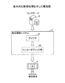
図11は、一実施形態に係る表示システム1100の機能構成の概要を示す図である。表示システム1100は、通信ネットワーク9に接続された、複数の通信端末5f1、5f2、5f3、配信制御システム2、及び端末管理システム7を有する。尚、図11の通信端末の数は一例であって、他の数であっても良い。また、通信端末5f2、5f3は、通信端末5f1と同様の構成を有している。   FIG. 11 is a diagram illustrating an outline of a functional configuration of the display system 1100 according to an embodiment. The display system 1100 includes a plurality of communication terminals 5 f 1, 5 f 2, 5 f 3, a distribution control system 2, and a terminal management system 7 connected to the communication network 9. Note that the number of communication terminals in FIG. 11 is an example, and other numbers may be used. Further, the communication terminals 5f2 and 5f3 have the same configuration as that of the communication terminal 5f1.

(通信端末)
通信端末5f1は、検知手段1101、送信手段1102、受信手段1104、及び表示手段1103を有している。検知手段1101は、他の通信端末5f2、5f3等が並べて設置されたとき等に、他の通信端末5f2、5f3等の相対的な位置を検知する。検知手段1101は、例えば、図8の位置検知部814等を含む。
(Communication terminal)
The communication terminal 5f1 includes a detection unit 1101, a transmission unit 1102, a reception unit 1104, and a display unit 1103. The detecting unit 1101 detects the relative positions of the other communication terminals 5f2, 5f3, etc. when the other communication terminals 5f2, 5f3, etc. are installed side by side. The detection unit 1101 includes, for example, the position detection unit 814 in FIG.

通信端末5f1の検知手段1101は、例えば、3つの通信端末5f1、5f2、5f3が、左から順に横並びで設置された場合、通信端末5f1の右側に通信端末5f2が設置されていることを検知する。また、通信端末5f2の検知手段1101は、通信端末5f2の左側に通信端末5f1が設置され、通信端末5f2の右側に通信端末5f3が設置されたことを検知する。さらに、通信端末5f3の検知手段1101は、通信端末5f3の左側に通信端末5f2が設置されていることを検知する。   For example, when three communication terminals 5f1, 5f2, and 5f3 are installed side by side in order from the left, the detection unit 1101 of the communication terminal 5f1 detects that the communication terminal 5f2 is installed on the right side of the communication terminal 5f1. . The detecting unit 1101 of the communication terminal 5f2 detects that the communication terminal 5f1 is installed on the left side of the communication terminal 5f2 and the communication terminal 5f3 is installed on the right side of the communication terminal 5f2. Furthermore, the detection means 1101 of the communication terminal 5f3 detects that the communication terminal 5f2 is installed on the left side of the communication terminal 5f3.

同様にして、通信端末5f1の検知手段1101は、3つの通信端末5f1、5f2、5f3が、上から順に縦並びで設置された場合、通信端末5f1の下側に通信端末5f2が設置されていることを検知する。また、通信端末5f2の検知手段1101は、通信端末5f2の上側に通信端末5f1が設置され、通信端末5f2の下側に通信端末5f3が設置されたことを検知する。さらに、通信端末5f3の検知手段1101は、通信端末5f3の上側に通信端末5f2が設置されていることを検知する。   Similarly, the detection unit 1101 of the communication terminal 5f1 has the communication terminal 5f2 below the communication terminal 5f1 when the three communication terminals 5f1, 5f2, and 5f3 are installed in the vertical order from the top. Detect that. The detecting unit 1101 of the communication terminal 5f2 detects that the communication terminal 5f1 is installed above the communication terminal 5f2 and the communication terminal 5f3 is installed below the communication terminal 5f2. Furthermore, the detection means 1101 of the communication terminal 5f3 detects that the communication terminal 5f2 is installed above the communication terminal 5f3.

通信端末5f1は、検知手段1101によって検知された通信端末5f2の相対的な位置を示す情報を含む端末位置情報を、送信手段1102を介して、端末管理システム7へ送信する。   The communication terminal 5f1 transmits terminal position information including information indicating the relative position of the communication terminal 5f2 detected by the detection unit 1101 to the terminal management system 7 via the transmission unit 1102.

通信端末5f1の表示手段1103は、端末管理システム7に送信した通信端末5f1の端末位置情報に基づいて、配信制御システム2が配信した画像データを、受信手段1104を介して取得し、例えば、図8の表示部804等に表示する。尚、図11の送信手段1102、及び受信手段1104は、1つの手段(送受信手段1105)であっても良いことは言うまでもない。   The display unit 1103 of the communication terminal 5f1 acquires the image data distributed by the distribution control system 2 through the reception unit 1104 based on the terminal position information of the communication terminal 5f1 transmitted to the terminal management system 7, for example, FIG. 8 on the display unit 804 or the like. Needless to say, the transmission unit 1102 and the reception unit 1104 in FIG. 11 may be a single unit (transmission / reception unit 1105).

(端末管理システム)
端末管理システム7は、通信手段1107、位置情報管理手段1108、及び記憶手段1109を有する。位置情報管理手段1108は、複数の通信端末5f1〜5f3から、通信手段1107を介して取得した複数の通信端末5f1〜5f3の端末位置情報を記憶手段1109に記憶する。また、位置情報管理手段1108は、取得した複数の通信端末5f1〜5f3の端末位置情報に基づいて、複数の通信端末5f1〜5f3の位置関係を特定する。
(Terminal management system)
The terminal management system 7 includes a communication unit 1107, a location information management unit 1108, and a storage unit 1109. The location information management unit 1108 stores the terminal location information of the plurality of communication terminals 5f1 to 5f3 acquired from the plurality of communication terminals 5f1 to 5f3 via the communication unit 1107 in the storage unit 1109. Further, the position information management unit 1108 specifies the positional relationship between the plurality of communication terminals 5f1 to 5f3 based on the acquired terminal position information of the plurality of communication terminals 5f1 to 5f3.

例えば、表示システム1100が3つの通信端末5f1〜5f3を有し、3つの通信端末5f1、5f2、5f3が、左から順に横並びで設置されているものとする。この場合、前述したように、通信端末5f1からは、右側に通信端末5f2が設置されていることを示す端末位置情報が通知される。同様に、通信端末5f2からは、左側に通信端末5f1が設置され、右側に通信端末5f3が設置されていることを示す端末位置情報が通知される。さらに、通信端末5f3からは、左側に通信端末5f2が設置されていることを示す端末位置情報が通知される。   For example, it is assumed that the display system 1100 includes three communication terminals 5f1 to 5f3, and the three communication terminals 5f1, 5f2, and 5f3 are installed side by side in order from the left. In this case, as described above, the terminal position information indicating that the communication terminal 5f2 is installed on the right side is notified from the communication terminal 5f1. Similarly, terminal location information indicating that the communication terminal 5f1 is installed on the left side and the communication terminal 5f3 is installed on the right side is notified from the communication terminal 5f2. Further, terminal position information indicating that the communication terminal 5f2 is installed on the left side is notified from the communication terminal 5f3.

位置情報管理手段1108は、上記3つの通信端末5f1〜5f3からの端末位置情報を用いて、3つの通信端末5f1〜5f3が、左から順に横並びで配置されていることを特定する。また、位置情報管理手段1108は、必要に応じて複数の通信端末5f1〜5f3に位置情報の検出及び送信を要求する機能を有していても良い。   The location information management means 1108 uses the terminal location information from the three communication terminals 5f1 to 5f3 to specify that the three communication terminals 5f1 to 5f3 are arranged side by side in order from the left. Further, the location information management unit 1108 may have a function of requesting detection and transmission of location information from the plurality of communication terminals 5f1 to 5f3 as necessary.

(配信制御システム)
配信制御システム2は、通信手段1110、データ提供手段1111、及び表示制御手段1106を有する。データ提供手段1111は、例えば、図5のブラウザ20等に相当し、通信端末5f1〜5f3に表示させる所定の画像データを提供する。
(Distribution control system)
The distribution control system 2 includes a communication unit 1110, a data providing unit 1111, and a display control unit 1106. The data providing unit 1111 corresponds to, for example, the browser 20 in FIG. 5 and provides predetermined image data to be displayed on the communication terminals 5f1 to 5f3.

表示制御手段1106は、端末管理システム7等から、複数の通信端末5f1〜5f3の位置関係を示す情報を取得し、取得した位置関係に基づいて、複数の通信端末5f1〜5f3に表示させる画像データを特定し、生成する。例えば、図5で説明したマルチディスプレイの構成により、複数の通信端末5f1〜5f3が協働して所定の画像を表示するように、所定の画像を3分割して、各通信端末が表示する画像を生成する。表示制御手段1106が生成した画像データは、通信手段1110を介して、通信端末5f1〜5f3にそれぞれ送信される。   The display control unit 1106 acquires information indicating the positional relationship between the plurality of communication terminals 5f1 to 5f3 from the terminal management system 7 and the like, and image data to be displayed on the plurality of communication terminals 5f1 to 5f3 based on the acquired positional relationship. Identify and generate For example, with the multi-display configuration described with reference to FIG. 5, an image displayed by each communication terminal by dividing the predetermined image into three so that the plurality of communication terminals 5f1 to 5f3 cooperate to display the predetermined image. Is generated. The image data generated by the display control unit 1106 is transmitted to the communication terminals 5f1 to 5f3 via the communication unit 1110.

上記構成により、表示システム1100では、複数の通信端末5f1〜5f3は、それぞれ隣接する通信端末に関する位置情報を検知して、端末管理システム7へ送信する。   With the above configuration, in the display system 1100, the plurality of communication terminals 5 f 1 to 5 f 3 detect position information related to adjacent communication terminals and transmit the position information to the terminal management system 7.

端末管理システム7は、複数の通信端末5f1〜5f3から受信した位置情報に基づいて、複数の通信端末5f1〜5f3の位置関係を特定する。また、端末管理システム7は、配信制御システム2が、複数の通信端末5f1〜5f3の各々に表示させる画像データを特定するための情報(複数の通信端末5f1〜5f3の位置関係を示す情報)を決定する。   The terminal management system 7 specifies the positional relationship between the plurality of communication terminals 5f1 to 5f3 based on the position information received from the plurality of communication terminals 5f1 to 5f3. The terminal management system 7 also has information (information indicating the positional relationship between the plurality of communication terminals 5f1 to 5f3) for specifying the image data that the distribution control system 2 displays on each of the plurality of communication terminals 5f1 to 5f3. decide.

配信制御システム2は、端末管理システム7が決定した、複数の通信端末5f1〜5f3の位置関係を示す情報に基づいて、複数の通信端末5f1〜5f3が表示する画像データを生成し、配信する。   The distribution control system 2 generates and distributes image data displayed by the plurality of communication terminals 5f1 to 5f3 based on information indicating the positional relationship between the plurality of communication terminals 5f1 to 5f3 determined by the terminal management system 7.

これにより、表示システム1100は、複数の通信端末5f1〜5f3の位置関係を特定して、複数の通信端末5f1〜5f3に所定の画像を表示させることを容易化することができる。例えば、表示システム1100は、複数の通信端末を新たに隣接配置した場合、隣接配置を解除した場合、又は通信端末5f1〜5f3の配置を変更した場合等、配置の変更に応じて、複数の通信端末が表示する画像を自動的に生成し、表示する。   Thereby, the display system 1100 can specify the positional relationship of the plurality of communication terminals 5f1 to 5f3, and can easily display a predetermined image on the plurality of communication terminals 5f1 to 5f3. For example, the display system 1100 has a plurality of communication terminals in response to a change in arrangement such as when a plurality of communication terminals are newly arranged adjacently, when the adjacent arrangement is canceled, or when the arrangement of the communication terminals 5f1 to 5f3 is changed. Automatically generate and display the image that the terminal displays.

次に、配信制御システム2、通信端末5、及び端末管理システム7について、さらに詳しく説明する。   Next, the distribution control system 2, the communication terminal 5, and the terminal management system 7 will be described in more detail.

(機能ブロック図)
図12は、主に配信制御システム2の各機能を示す機能ブロック図である。図12では、配信制御システム2が通信端末5f1に対して映像(音)データを配信する場合の機能構成が示されているが、配信先が通信端末5f1以外の場合も、同じ機能構成を有する。なお、配信制御システム2は、複数の配信エンジンサーバを備えているが、説明を簡単にするために、以下では、単一の配信エンジンサーバを備えている場合について説明する。
(Function block diagram)
FIG. 12 is a functional block diagram mainly showing each function of the distribution control system 2. Although FIG. 12 shows a functional configuration when the distribution control system 2 distributes video (sound) data to the communication terminal 5f1, the same functional configuration is provided even when the distribution destination is other than the communication terminal 5f1. . The distribution control system 2 includes a plurality of distribution engine servers. However, in order to simplify the description, a case where a single distribution engine server is included will be described below.

(配信制御システムの機能構成)
図12に示されているように、配信制御システム2は、図9に示されているCPU201等のハードウェア構成及びプログラムによって、図12に示されている各機能構成を有する。
(Functional configuration of distribution control system)
As shown in FIG. 12, the distribution control system 2 has each functional configuration shown in FIG. 12 by a hardware configuration and a program such as the CPU 201 shown in FIG.

具体的に、配信制御システム2は、ブラウザ20、送受信部21、ブラウザ管理部22、送信用FIFO24、時刻管理部25、時刻取得部26、回線適応制御部27、エンコーダブリッジ部30、送受信部31、受信用FIFO34、認識部35、遅延情報取得部37a、回線適応制御部37b、及びデコード部40を有している。更に、配信制御システム2は、図9に示されているHDD204によって構築される記憶部2000を有している。この記憶部2000には、認識部35から出力されブラウザ管理部22を介して送られた後述の認識情報が記憶される。なお、ブラウザ20が取得したコンテンツデータは、キャッシュとして、記憶部2000に一時的に記憶しておくこともできる。   Specifically, the distribution control system 2 includes a browser 20, a transmission / reception unit 21, a browser management unit 22, a transmission FIFO 24, a time management unit 25, a time acquisition unit 26, a line adaptive control unit 27, an encoder bridge unit 30, and a transmission / reception unit 31. A receiving FIFO 34, a recognizing unit 35, a delay information acquiring unit 37a, a line adaptive control unit 37b, and a decoding unit 40. Further, the distribution control system 2 has a storage unit 2000 constructed by the HDD 204 shown in FIG. The storage unit 2000 stores later-described recognition information output from the recognition unit 35 and sent via the browser management unit 22. The content data acquired by the browser 20 can be temporarily stored in the storage unit 2000 as a cache.

上述の各機能構成のうち、ブラウザ20は、配信制御システム2内で動作するウェブブラウザである。ブラウザ20は、ウェブコンテンツのリッチ化に対応させて常に最新化されている。ブラウザ20は、例えば、Media Player、Flash Player、JavaScript(登録商標)、CSS及びHTMLレンダラを有する。なお、JavaScriptには、標準規格のものと配信システム1独自のものが含まれる。   Among the functional configurations described above, the browser 20 is a web browser that operates within the distribution control system 2. The browser 20 is constantly updated in response to the richness of web content. The browser 20 includes, for example, Media Player, Flash Player, JavaScript (registered trademark), CSS, and HTML renderer. Note that JavaScript includes standards and standards unique to the distribution system 1.

ここで、Media Playerは、映像(音)ファイルなどのマルチメディアファイルをブラウザ20内で再生するためのブラウザプラグインである。Flash Playerは、Flashコンテンツをブラウザ20内で再生するためのブラウザプラグインである。独自のJavaScriptは、配信システム1に固有のサービスのAPI(Application Programming Interface)を提供するJavaScript群である。CSSは、HTMLで記述されたウェブページの見栄えやスタイルを効率的に定義するための技術である。HTMLレンダラは、HTMLレンダリングエンジンである。   Here, Media Player is a browser plug-in for reproducing multimedia files such as video (sound) files in the browser 20. Flash Player is a browser plug-in for reproducing Flash content in the browser 20. The unique JavaScript is a JavaScript group that provides an API (Application Programming Interface) of a service unique to the distribution system 1. CSS is a technology for efficiently defining the appearance and style of a web page described in HTML. The HTML renderer is an HTML rendering engine.

レンダラは、画像(音)データとしてのウェブコンテンツデータ等のコンテンツデータをレンダリングすることにより、静止画(音)データとしての各フレームデータを生成する。また、レンダラは、図7に示されているように、複数種類のコンテンツ(〔A〕,〔p1〕,〔p2〕,〔E1〕,〔E2〕)のレイアウトを行うレイアウトエンジン(Layout Engine)でもある。   The renderer renders content data such as web content data as image (sound) data, thereby generating each frame data as still image (sound) data. Also, as shown in FIG. 7, the renderer is a layout engine (Layout Engine) that performs layout of a plurality of types of content ([A], [p1], [p2], [E1], [E2]). But there is.

また、本実施形態の配信システム1では、配信制御システム2内に複数のブラウザ20を用意しており、これら複数のブラウザ20の中からユーザセッションに使用するクラウドブラウザが選択される。なお、ここでは、説明を簡略化するため、単一のブラウザ20が用意されている場合について、以下続けて説明する。   Further, in the distribution system 1 of the present embodiment, a plurality of browsers 20 are prepared in the distribution control system 2, and a cloud browser to be used for a user session is selected from the plurality of browsers 20. Here, in order to simplify the description, the case where a single browser 20 is prepared will be described below.

送受信部21は、端末管理システム7やウェブサーバ8との間で、各種データ、各種要求、各種指示等の送受信を行う。例えば、送受信部21は、ウェブサーバ8のコンテンツサイトからウェブコンテンツデータを取得する。また、送受信部21は、端末管理システム7から取得した各種データを配信制御システム2内の各機能構成に出力したり、端末管理システム7から取得した各種データ、各種要求、又は各種指示等に基づいて配信制御システム2内の各機能構成を制御したりする。例えば、ブラウザ20が複数ある場合、送受信部21は、端末管理システム7からの配信のパターンの切替え要求をブラウザ管理部22に出力し、ブラウザ管理部22が、複数のブラウザ20における一のブラウザから他のブラウザへの切替えを制御する。また、送受信部21は、端末管理システム7からの配信の切替え要求に基づいて、図13及び図14に示されているエンコーダブリッジ部30内の各構成の組み合わせの切替えを行う。   The transmission / reception unit 21 transmits / receives various data, various requests, various instructions, and the like to / from the terminal management system 7 and the web server 8. For example, the transmission / reception unit 21 acquires web content data from the content site of the web server 8. Further, the transmission / reception unit 21 outputs various data acquired from the terminal management system 7 to each functional configuration in the distribution control system 2, or based on various data acquired from the terminal management system 7, various requests, or various instructions. Thus, each functional configuration in the distribution control system 2 is controlled. For example, when there are a plurality of browsers 20, the transmission / reception unit 21 outputs a distribution pattern switching request from the terminal management system 7 to the browser management unit 22, and the browser management unit 22 starts from one browser among the plurality of browsers 20. Controls switching to another browser. Further, the transmission / reception unit 21 switches the combination of the components in the encoder bridge unit 30 shown in FIGS. 13 and 14 based on the distribution switching request from the terminal management system 7.

ブラウザ管理部22は、ブラウザ20の管理を行う。例えば、ブラウザ管理部22は、ブラウザ20に、起動又は終了を指示したり、起動又は終了時にエンコーダIDを採番したりする。ここで、エンコーダIDは、ブラウザ管理部22がエンコーダブリッジ部30のプロセスを管理するために採番する識別情報である。   The browser management unit 22 manages the browser 20. For example, the browser management unit 22 instructs the browser 20 to start or end, or assigns an encoder ID at the time of start or end. Here, the encoder ID is identification information that is assigned by the browser management unit 22 to manage the process of the encoder bridge unit 30.

また、ブラウザ管理部22は、ブラウザ20が起動されるたびに、ブラウザIDを採番して管理する。ここで、ブラウザIDは、ブラウザ管理部22がブラウザ20のプロセスを管理するために採番し、ブラウザ20を識別するための識別情報である。   The browser management unit 22 assigns and manages a browser ID every time the browser 20 is activated. Here, the browser ID is identification information for identifying the browser 20 by the browser management unit 22 in order to manage the process of the browser 20.

さらに、ブラウザ管理部22は、送受信部21を介して、端末管理システム7から、複数の通信端末5f1〜5f3の位置関係を示す情報である端末位置情報を取得する。ブラウザ管理部22は、取得した端末位置情報に応じて、ブラウザ20に読込まれた情報を、予め定められたルールや指示によって、変形、分割、又は合成など処理を行う指示を、エンコーダブリッジ部30に送信する。尚、ブラウザ管理部22及びエンコーダブリッジ部30は、例えば、図11の表示制御手段1106に含まれる。   Furthermore, the browser management unit 22 acquires terminal position information, which is information indicating the positional relationship between the plurality of communication terminals 5f1 to 5f3, from the terminal management system 7 via the transmission / reception unit 21. The browser management unit 22 gives an instruction to perform processing such as transformation, division, or composition on information read into the browser 20 according to predetermined rules and instructions according to the acquired terminal position information. Send to. The browser management unit 22 and the encoder bridge unit 30 are included in, for example, the display control unit 1106 in FIG.

また、ブラウザ管理部22は、送受信部31を介して通信端末5から、各種操作データを取得し、ブラウザ20に出力する。なお、操作データは、通信端末5での操作イベント(キーボード211やマウス212等による操作や電子ペンPによるストローク等)によって生じたデータである。通信端末5に、温度センサ、湿度センサ、及び加速度センサ等の各種センサが設けられている場合には、ブラウザ管理部22は、通信端末5から各センサの出力信号であるセンサ情報を取得し、ブラウザ20に出力する。更に、ブラウザ管理部22は、認識部35から画像(音)データを取得してブラウザ20に出力したり、認識部35から後述の認識情報を取得して記憶部2000に記憶したりする。また、ブラウザ管理部22は、受信用FIFO34から映像(音)データを取得してブラウザ20に出力する。   Further, the browser management unit 22 acquires various operation data from the communication terminal 5 via the transmission / reception unit 31 and outputs the operation data to the browser 20. The operation data is data generated by an operation event (such as an operation with the keyboard 211 or the mouse 212 or a stroke with the electronic pen P) in the communication terminal 5. When the communication terminal 5 is provided with various sensors such as a temperature sensor, a humidity sensor, and an acceleration sensor, the browser management unit 22 acquires sensor information that is an output signal of each sensor from the communication terminal 5, Output to the browser 20. Further, the browser management unit 22 acquires image (sound) data from the recognition unit 35 and outputs the image (sound) data to the browser 20, or acquires recognition information described later from the recognition unit 35 and stores it in the storage unit 2000. In addition, the browser management unit 22 acquires video (sound) data from the reception FIFO 34 and outputs it to the browser 20.

送信用FIFO24は、ブラウザ20で生成された静止画(音)データとしての各フレームデータを格納するバッファである。   The transmission FIFO 24 is a buffer for storing each frame data as still image (sound) data generated by the browser 20.

時刻管理部25は、配信制御システム2独自の時刻Tを管理している。   The time management unit 25 manages the time T unique to the distribution control system 2.

時刻取得部26は、後述の通信端末5における時刻制御部56と連携して、時刻調整の処理を行う。具体的には、時刻取得部26は、時刻管理部25から配信制御システム2における時刻Tを示す時刻情報(T)を取得したり、送受信部31及び送受信部51を介して、後述の時刻制御部56から通信端末5における時刻tを示す時刻情報(t)を受信したり、時刻制御部56に時刻情報(t)及び時刻情報(T)を送信する。   The time acquisition unit 26 performs time adjustment processing in cooperation with a time control unit 56 in the communication terminal 5 described later. Specifically, the time acquisition unit 26 acquires time information (T) indicating the time T in the distribution control system 2 from the time management unit 25, or time control described later via the transmission / reception unit 31 and the transmission / reception unit 51. The time information (t) indicating the time t in the communication terminal 5 is received from the unit 56, or the time information (t) and the time information (T) are transmitted to the time control unit 56.

回線適応制御部27は、送信遅延時間情報(D)に基づいて、再生遅延時間Uを計算したり、エンコーダブリッジ部30における変換部10のフレームレートやデータの解像度等の動作条件を計算したりする。この再生遅延時間は、再生までにデータがバッファリングされることで、再生を遅延させるための時間である。   The line adaptation control unit 27 calculates the reproduction delay time U based on the transmission delay time information (D), and calculates the operating conditions such as the frame rate and data resolution of the conversion unit 10 in the encoder bridge unit 30. To do. This reproduction delay time is a time for delaying reproduction by buffering data before reproduction.

エンコーダブリッジ部30は、ブラウザ20が生成した静止画(音)データとしての各フレームデータを、エンコーダブリッジ部30における後述の変換部10に出力する。エンコーダブリッジ部30については、図13及び図14を用いて、更に詳細に説明する。   The encoder bridge unit 30 outputs each frame data as still image (sound) data generated by the browser 20 to the conversion unit 10 described later in the encoder bridge unit 30. The encoder bridge unit 30 will be described in more detail with reference to FIGS. 13 and 14.

図13は、エンコーダブリッジ部の詳細図である。また、図14は、変換部の各機能を示す機能ブロック図である。   FIG. 13 is a detailed view of the encoder bridge unit. FIG. 14 is a functional block diagram showing each function of the conversion unit.

図13に示されているように、エンコーダブリッジ部30は、作成・選択部310、及び選択部320と、これらの間に複数の変換部(10a,10b,10c)が構築されている。ここでは、3つの変換部を示したが、いくつであってもよい。なお、以下、任意の変換部を「変換部10」として表す。   As shown in FIG. 13, the encoder bridge unit 30 includes a creation / selection unit 310, a selection unit 320, and a plurality of conversion units (10a, 10b, 10c) between them. Here, three conversion units are shown, but any number may be used. Hereinafter, an arbitrary conversion unit is expressed as “conversion unit 10”.

更に、変換部10は、ブラウザ20によって生成された静止画(音)データとしての各フレームデータのデータ形式を、通信ネットワーク9を介して通信端末5に配信できるH.264等のデータ形式に変換する。そのため、変換部10は、図14に示されているように、トリミング部11、リサイズ部12、分割部13、及びエンコード部19を有する。トリミング部11、リサイズ部12、及び分割部13は、音データの場合は、処理を行わない。   Further, the conversion unit 10 can distribute the data format of each frame data as still image (sound) data generated by the browser 20 to the communication terminal 5 via the communication network 9. It is converted into a data format such as H.264. Therefore, the conversion unit 10 includes a trimming unit 11, a resizing unit 12, a dividing unit 13, and an encoding unit 19, as shown in FIG. The trimming unit 11, the resizing unit 12, and the dividing unit 13 do not perform processing in the case of sound data.

このうち、トリミング部11は、静止画の一部だけを切り出す処理を行う。リサイズ部12は、静止画の縮尺を変更する。分割部13は、図5に示されているように、静止画を分割する。   Among these, the trimming unit 11 performs a process of cutting out only a part of the still image. The resizing unit 12 changes the scale of the still image. The dividing unit 13 divides the still image as shown in FIG.

また、エンコード部19は、ブラウザ20で生成された、静止画(音)データとしての各フレームデータをエンコードすることにより、通信ネットワーク9介して通信端末5に映像(音)データを配信できるように変換する。また、エンコード部19は、映像が動かなければ(フレーム間で変化がなければ)、以降、映像が動くまでスキップフレームを挿入することで帯域をセーブする。   In addition, the encoding unit 19 can distribute video (sound) data to the communication terminal 5 via the communication network 9 by encoding each frame data as still image (sound) data generated by the browser 20. Convert. In addition, if the video does not move (if there is no change between frames), the encoding unit 19 subsequently saves the bandwidth by inserting skip frames until the video moves.

なお、レンダリングにより静止画データと共に音データが生成される場合には、これら両方のデータがエンコードされるが、音データだけが生成される場合には、トリミングやリサイズ、分割は行われることはなく、エンコードだけが行われてデータ圧縮される。   When sound data is generated together with still image data by rendering, both of these data are encoded. However, when only sound data is generated, trimming, resizing, and division are not performed. Only the encoding is performed and the data is compressed.

また、作成・選択部310は、新たに変換部10を作成したり、既に作成されている変換部10に対して入力させる静止画(音)データとしてのフレームデータを選択したりする。作成する場合としては、作成・選択部310は、通信端末5おける映像(音)データの再生能力に応じた変換が可能な変換部10を作成する。また、選択する場合としては、既に作成されている変換部10を選択する。例えば、通信端末5aへの配信に加えて通信端末5bへの配信を開始するにあたって、通信端末5aへ配信している映像(音)データと同じ映像(音)データを通信端末5bへ配信する場合がある。このような場合で、更に、通信端末5bが通信端末5aにおける映像(音)データの再生能力と同じ再生能力を有する場合には、作成・選択部310は通信端末5b用に新たな変換部10bを作成せずに、通信端末5a用に既に作成している変換部10aを利用する。   In addition, the creation / selection unit 310 creates a new conversion unit 10 or selects frame data as still image (sound) data to be input to the conversion unit 10 that has already been created. In the case of creation, the creation / selection unit 310 creates the conversion unit 10 that can perform conversion according to the reproduction capability of video (sound) data in the communication terminal 5. Moreover, as a case of selection, the conversion unit 10 that has already been created is selected. For example, when starting distribution to the communication terminal 5b in addition to distribution to the communication terminal 5a, the same video (sound) data as the video (sound) data distributed to the communication terminal 5a is distributed to the communication terminal 5b. There is. In such a case, when the communication terminal 5b has the same reproduction capability as the reproduction capability of the video (sound) data in the communication terminal 5a, the creation / selection unit 310 adds a new conversion unit 10b for the communication terminal 5b. Without using the conversion unit 10a already created for the communication terminal 5a.

一方、選択部320は、既に作成されている変換部10から所望のものを選択する。これら作成・選択部310と選択部320による選択によって、図7に示したような様々なパターンの配信を行うことができる。   On the other hand, the selection unit 320 selects a desired one from the conversion units 10 that have already been created. By the selection by the creation / selection unit 310 and the selection unit 320, various patterns as shown in FIG. 7 can be distributed.

図12に戻って、配信制御システム2の機能構成の説明を続ける。送受信部31は、通信端末5との間で、各種データや要求等の送受信を行う。この送受信部31が、クラウド上から通信ネットワーク9を介して通信端末5に各種データや要求等の送信を行うことで、配信制御システム2は通信端末5に対して、各種データや要求等を配信することができる。例えば、送受信部31は、通信端末5のログイン処理において、通信端末5の送受信部51に対し、ユーザにログイン要求を促すための認証画面データを送信する。その他に、送受信部31は、HTTPS(Hypertext Transfer Protocol over Secure Socket Layer)サーバを介して配信システム1独自のプロトコルにより、通信端末5のユーザアプリや通信端末6のデバイスアプリへのデータ送信およびデータ受信を行う。この独自のプロトコルは、配信制御システム2と通信端末との間でリアルタイムに途切れることなくデータを送受信するためのHTTPSベースのアプリケーション層プロトコルである。また、送受信部31は、送信レスポンス制御、リアルタイムのデータ作成、コマンド送信、受信レスポンス制御、受信データ分析、及びジェスチャ変換を行う。   Returning to FIG. 12, the description of the functional configuration of the distribution control system 2 will be continued. The transmission / reception unit 31 transmits / receives various data and requests to / from the communication terminal 5. The transmission / reception unit 31 transmits various data and requests to the communication terminal 5 from the cloud via the communication network 9, so that the distribution control system 2 distributes various data and requests to the communication terminal 5. can do. For example, the transmission / reception unit 31 transmits authentication screen data for prompting the user to log in to the transmission / reception unit 51 of the communication terminal 5 in the login process of the communication terminal 5. In addition, the transmission / reception unit 31 transmits and receives data to the user application of the communication terminal 5 and the device application of the communication terminal 6 using a protocol unique to the distribution system 1 via an HTTPS (Hypertext Transfer Protocol over Secure Socket Layer) server. I do. This unique protocol is an HTTPS-based application layer protocol for transmitting and receiving data between the distribution control system 2 and the communication terminal in real time without interruption. The transmission / reception unit 31 performs transmission response control, real-time data creation, command transmission, reception response control, reception data analysis, and gesture conversion.

このうち、送信レスポンス制御は、配信制御システム2から通信端末5にデータを送信するために、通信端末5からリクエスト(要求)されたダウンロード用のHTTPSセッションを管理する処理である。このダウンロード用のHTTPSセッションのレスポンスはすぐに終了せず、一定時間(1〜数分)保持する。送受信部31は、通信端末5に送るデータを動的にレスポンスのBody部に書き込む。また、再接続のコストをなくすため、通信端末からは前のセッションが終了しないうちに別のリクエストが届くようにする。送受信部31を、前のリクエストが完了するまで待機させておくようにすることで、再接続を行っても、オーバヘッドを削除することができる。   Among these, the transmission response control is a process for managing a download HTTPS session requested (requested) from the communication terminal 5 in order to transmit data from the distribution control system 2 to the communication terminal 5. The response of the download HTTPS session does not end immediately, but is held for a certain time (1 to several minutes). The transmission / reception unit 31 dynamically writes the data to be transmitted to the communication terminal 5 in the body part of the response. In order to eliminate the cost of reconnection, another request is received from the communication terminal before the previous session ends. By making the transmission / reception unit 31 wait until the previous request is completed, the overhead can be deleted even if reconnection is performed.

リアルタイムのデータ作成は、図14におけるエンコード部19で生成された圧縮映像(および圧縮音)のデータに独自のヘッダを付与して、HTTPSのBody部に書き込む処理である。   The real-time data creation is a process of adding a unique header to the compressed video (and compressed sound) data generated by the encoding unit 19 in FIG. 14 and writing it in the body part of HTTPS.

コマンド送信は、通信端末5に送信するコマンドデータを生成し、通信端末5へのHTTPSのBody部に書き込む処理である。   The command transmission is a process for generating command data to be transmitted to the communication terminal 5 and writing it in the Body part of HTTPS to the communication terminal 5.

受信レスポンス制御は、配信制御システム2が通信端末5からデータを受信するために、通信端末5からリクエストされたHTTPSセッションを管理する処理である。このHTTPSセッションのレスポンスはすぐに終了せず、一定時間(1〜数分)保持される。通信端末5は、配信制御システム2の送受信部31に送るデータを動的にリクエストのBody部に書き込む。   The reception response control is a process for managing an HTTPS session requested from the communication terminal 5 in order for the distribution control system 2 to receive data from the communication terminal 5. The response of this HTTPS session does not end immediately, but is held for a certain time (1 to several minutes). The communication terminal 5 dynamically writes the data to be sent to the transmission / reception unit 31 of the distribution control system 2 in the Body part of the request.

受信データ分析は、通信端末5から送られてきたデータを種別ごとに分析し、必要なプロセスにデータを渡す処理である。   The received data analysis is a process of analyzing data sent from the communication terminal 5 for each type and passing the data to a necessary process.

ジェスチャ変換は、ユーザが電子黒板としての通信端末5fに電子ペンや手書きにより入力したジェスチャイベントを、ブラウザ20が受け取れる形式のデータに変換する処理である。   Gesture conversion is a process of converting a gesture event input by the user into the communication terminal 5f as an electronic blackboard with an electronic pen or handwriting into data in a format that the browser 20 can receive.

また、受信用FIFO34は、デコード部40でデコードされた後の映像(音)データを格納するバッファである。   The reception FIFO 34 is a buffer for storing video (sound) data after being decoded by the decoding unit 40.

認識部35は、通信端末5から受信する画像(音)データに対しての処理を行う。具体的には、認識部35は、例えば、サイネージ向けにカメラ62で撮影された画像から人や動物の顔、年齢、及び性別などを認識する。また、認識部35は、オフィス向けに、カメラ62で撮影された画像から顔認識による名前タグ付けや背景画像の差し替え処理などを行う。認識部35は、認識した内容を示す認識情報を記憶部2000に記憶させる。この認識部35は、認識拡張ボードで処理を行うことで高速化が実現される。   The recognition unit 35 performs processing on image (sound) data received from the communication terminal 5. Specifically, the recognition unit 35 recognizes, for example, the face, age, and sex of a person or animal from an image taken by the camera 62 for signage. Further, the recognition unit 35 performs name tagging by face recognition, background image replacement processing, and the like from the image taken by the camera 62 for the office. The recognition unit 35 causes the storage unit 2000 to store recognition information indicating the recognized content. The recognition unit 35 is speeded up by performing processing with a recognition expansion board.

遅延情報取得部37aは、上り用の回線適応制御の処理に用いられる遅延情報取得部57に対応して、下り用の回線適応制御の処理に用いられる。具体的には、遅延情報取得部37aは、デコード部40から送信遅延時間d1を示す送信遅延時間情報(d1)を取得して一定時間保持しておき、複数の送信遅延時間情報(d1)を取得したところで、回線適応制御部37bに、複数の送信遅延時間d1による度数分布情報を示す送信遅延時間情報(d)を出力する。   The delay information acquisition unit 37a is used for downlink channel adaptive control processing corresponding to the delay information acquisition unit 57 used for uplink channel adaptive control processing. Specifically, the delay information acquisition unit 37a acquires transmission delay time information (d1) indicating the transmission delay time d1 from the decoding unit 40, holds the transmission delay time information (d1) for a predetermined time, and stores a plurality of transmission delay time information (d1). Once acquired, transmission delay time information (d) indicating frequency distribution information based on a plurality of transmission delay times d1 is output to the line adaptive control unit 37b.

回線適応制御部37bは、上り用の回線適応制御の処理に用いられる回線適応制御部27に対応して、下り用の回線適応制御の処理に用いられる。具体的には、回線適応制御部37bは、送信遅延時間情報(d)に基づいて、エンコード部60の動作条件を計算する。また、回線適応制御部37bは、送受信部31及び送受信部51を介して通信端末5のエンコード部60に、フレームレートやデータの解像度等の動作条件を示す回線適応制御信号を送信する。   The channel adaptation control unit 37b is used for downlink channel adaptation control processing corresponding to the channel adaptation control unit 27 used for uplink channel adaptation control processing. Specifically, the line adaptive control unit 37b calculates the operating condition of the encoding unit 60 based on the transmission delay time information (d). Also, the line adaptation control unit 37b transmits a line adaptation control signal indicating operation conditions such as a frame rate and data resolution to the encoding unit 60 of the communication terminal 5 via the transmission / reception unit 31 and the transmission / reception unit 51.

デコード部40は、通信端末5から送信されて来た画像(音)データをデコードする。   The decoding unit 40 decodes image (sound) data transmitted from the communication terminal 5.

(通信端末の機能構成)
続いて、通信端末5の機能構成について説明する。通信端末5は、ユーザが配信システム1へのログインや映像(音)データの配信の開始又は停止などを行うためのインターフェースとなる端末である。尚、通信端末5は、本発明に係る表示装置の一例である。
(Functional configuration of communication terminal)
Next, the functional configuration of the communication terminal 5 will be described. The communication terminal 5 is a terminal that serves as an interface for a user to log in to the distribution system 1 or start or stop distribution of video (sound) data. The communication terminal 5 is an example of a display device according to the present invention.

図15は、一実施形態に係る通信端末5の機能ブロック図である。通信端末5は、デコード部50、送受信部51、操作部805、再生制御部53、レンダリング部55、時刻制御部56、遅延情報取得部57、表示部804、エンコード部60、及び位置検知部814を有している。更に、通信端末5は、図8に示されているRAM803によって構築される記憶部5000を有している。この記憶部5000には、後述の時刻差Δを示す時刻差情報(Δ)、及び通信端末5における時刻tを示す時刻情報(t)等が記憶される。   FIG. 15 is a functional block diagram of the communication terminal 5 according to an embodiment. The communication terminal 5 includes a decoding unit 50, a transmission / reception unit 51, an operation unit 805, a reproduction control unit 53, a rendering unit 55, a time control unit 56, a delay information acquisition unit 57, a display unit 804, an encoding unit 60, and a position detection unit 814. have. Further, the communication terminal 5 has a storage unit 5000 constructed by the RAM 803 shown in FIG. The storage unit 5000 stores time difference information (Δ) indicating a time difference Δ described later, time information (t) indicating a time t in the communication terminal 5, and the like.

このうち、デコード部50は、配信制御システム2から配信され、再生制御部53から出力された映像(音)データをデコードする。   Among these, the decoding unit 50 decodes the video (sound) data distributed from the distribution control system 2 and output from the reproduction control unit 53.

送受信部51は、配信制御システム2の送受信部31、及び後述の端末管理システム7の送受信部71aとの間で、各種データや要求等の送受信を行う。例えば、送受信部51は、通信端末5のログイン処理において、操作部52による通信端末5の起動に基づき、端末管理システム7の送受信部71にログイン要求を行う。   The transmission / reception unit 51 transmits and receives various data and requests between the transmission / reception unit 31 of the distribution control system 2 and the transmission / reception unit 71a of the terminal management system 7 described later. For example, in the login process of the communication terminal 5, the transmission / reception unit 51 makes a login request to the transmission / reception unit 71 of the terminal management system 7 based on the activation of the communication terminal 5 by the operation unit 52.

操作部52は、ユーザの操作入力を受け付ける処理を行い、例えば、電源スイッチ、キーボード、マウス、電子ペンP等による入力や選択等を受け付け、操作データとして配信制御システム2のブラウザ管理部22に送信する。   The operation unit 52 performs a process of accepting a user's operation input. For example, the operation unit 52 accepts input or selection using a power switch, a keyboard, a mouse, an electronic pen P, and the like, and transmits the operation data to the browser management unit 22 of the distribution control system 2. To do.

再生制御部53は、送受信部51から受けた映像(音)データ(リアルタイムデータのパケット)をバッファリングし、再生遅延時間Uを考慮してデコード部50に出力する。   The reproduction control unit 53 buffers the video (sound) data (real-time data packet) received from the transmission / reception unit 51 and outputs it to the decoding unit 50 in consideration of the reproduction delay time U.

レンダリング部55は、デコード部50によってデコードされたデータをレンダリングする。   The rendering unit 55 renders the data decoded by the decoding unit 50.

時刻制御部56は、配信制御システム2の時刻取得部26と連携して、時刻調整の処理を行う。具体的には、時刻制御部56は、記憶部5000から通信端末5における時刻tを示す時刻情報(t)を取得する。また、時刻制御部56は、送受信部51及び送受信部31を介して、配信制御システム2の時刻取得部26に、配信制御システム2における時刻Tを示す時刻情報(T)を要求する。この場合、時刻情報(T)の要求と共に、時刻情報(t)が送信される。   The time control unit 56 performs time adjustment processing in cooperation with the time acquisition unit 26 of the distribution control system 2. Specifically, the time control unit 56 acquires time information (t) indicating the time t in the communication terminal 5 from the storage unit 5000. The time control unit 56 requests time information (T) indicating the time T in the distribution control system 2 from the time acquisition unit 26 of the distribution control system 2 via the transmission / reception unit 51 and the transmission / reception unit 31. In this case, time information (t) is transmitted together with a request for time information (T).

遅延情報取得部57は、再生制御部53から送信遅延時間D1を示す送信遅延時間情報(D1)を取得して一定時間保持しておき、複数の送信遅延時間情報(D1)を取得したところで、送受信部51及び送受信部31を介して回線適応制御部27に、複数の送信遅延時間D1による度数分布情報を示す送信遅延時間情報(D)を送信する。なお、送信遅延時間情報(D)は、例えば、100フレームに1回送信される。   The delay information acquisition unit 57 acquires the transmission delay time information (D1) indicating the transmission delay time D1 from the reproduction control unit 53, holds the transmission delay time information for a certain time, and acquires the plurality of transmission delay time information (D1). Transmission delay time information (D) indicating frequency distribution information based on a plurality of transmission delay times D1 is transmitted to the line adaptation control unit 27 via the transmission / reception unit 51 and the transmission / reception unit 31. The transmission delay time information (D) is transmitted once every 100 frames, for example.

表示部58は、レンダリング部55によってレンダリングされたデータを再生する。   The display unit 58 plays back the data rendered by the rendering unit 55.

エンコード部60は、内蔵されたマイク部812や、外付けのカメラ62及びマイク63から取得してエンコードした映像(音)データ〔E〕と、記憶部5000から取得した現時点の通信端末5における時刻tを示す時刻情報(t)と、同じく記憶部5000から取得した時間差Δを示す時間差情報(Δ)を、送受信部51及び送受信部31を介して、配信制御システム2のデコード部40に送信する。また、エンコード部60は、回線適応制御部37bから受信した回線適応制御信号で示される動作条件に基づいて、エンコード部60の動作条件を変更する。更に、エンコード部60は、新たな動作条件に従って、カメラ62及びマイク63から取得してエンコードした映像(音)データ〔E〕と、記憶部5000から取得した現時点の通信端末5における時刻tを示す時刻情報(t)と、記憶部5000から取得した時間差Δを示す時間差情報(Δ)とを、送受信部51及び送受信部31を介して、配信制御システム2のデコード部40に送信する。 The encoding unit 60 includes video (sound) data [E] acquired and encoded from the built-in microphone unit 812, the external camera 62 and the microphone 63, and the current time in the communication terminal 5 acquired from the storage unit 5000. and time information indicating the t 0 (t 0), also the obtained time difference information indicating a time difference delta from the storage unit 5000 (delta), via the transceiver 51 and the transceiver 31, the decoding unit 40 of the distribution control system 2 Send. In addition, the encoding unit 60 changes the operation condition of the encoding unit 60 based on the operation condition indicated by the channel adaptation control signal received from the channel adaptation control unit 37b. Furthermore, the encoding unit 60 uses the video (sound) data [E] acquired and encoded from the camera 62 and the microphone 63 according to the new operation condition, and the current time t 0 in the communication terminal 5 acquired from the storage unit 5000. The time information (t 0 ) indicated and the time difference information (Δ) indicating the time difference Δ acquired from the storage unit 5000 are transmitted to the decoding unit 40 of the distribution control system 2 via the transmission / reception unit 51 and the transmission / reception unit 31.

なお、内蔵されたマイク部812、外付けのカメラ62及びマイク63等は、入力手段の一例であり、エンコードやデコードが必要な各種デバイスである。入力手段は、映像(音)データの他に、触覚(touch)データや嗅覚(smell)データを出力することができてもよい。   The built-in microphone unit 812, the external camera 62, the microphone 63, and the like are examples of input means, and are various devices that require encoding and decoding. The input means may be capable of outputting touch data and smell data in addition to video (sound) data.

入力手段には、温度センサ、方位センサ、加速度センサ等の各種センサも含まれる。   The input means includes various sensors such as a temperature sensor, a direction sensor, and an acceleration sensor.

位置検知部814は、他の表示装置に対する位置を示す情報を含む端末位置情報を取得する。また、位置検知部814は、取得した位置情報(端末位置情報1201)を、送受信部51を介して端末管理システム7へ送信する。   The position detection unit 814 acquires terminal position information including information indicating a position with respect to another display device. Further, the position detection unit 814 transmits the acquired position information (terminal position information 1201) to the terminal management system 7 via the transmission / reception unit 51.

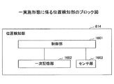
図16は、一実施形態に係る位置検知部814のブロック図である。位置検知部814は、制御部1601、一次記憶部1602、センサ部1603を有する。制御部1601は、位置検知部814の制御を行うブロックで、例えば、図8のCPU801で動作するプログラム等により実現される。一次記憶部1602は、センサ部1603から取得した情報を記憶する手段で、例えば、図8のRAM803や、ストレージ部806等に含まれる。センサ部1603は、例えば、図8の表示部804の複数の辺(例えば4辺)に設けられ、隣接して配置された、他の通信端末5f2の位置情報を検知する。   FIG. 16 is a block diagram of the position detection unit 814 according to an embodiment. The position detection unit 814 includes a control unit 1601, a primary storage unit 1602, and a sensor unit 1603. The control unit 1601 is a block that controls the position detection unit 814, and is realized by, for example, a program that operates on the CPU 801 in FIG. The primary storage unit 1602 is means for storing information acquired from the sensor unit 1603, and is included in, for example, the RAM 803 and the storage unit 806 in FIG. For example, the sensor unit 1603 is provided on a plurality of sides (for example, four sides) of the display unit 804 in FIG. 8 and detects position information of other communication terminals 5f2 arranged adjacent to each other.

上記構成により、制御部1601は、例えば、所定の時間間隔(例えば1秒間隔)で、センサ部1603から、他の通信端末の位置情報を取得し、一次記憶部1602に記憶する。さらに、制御部1601は、例えば、端末管理システム7からの要求に応じて、或いは、所定の時間間隔で、一次記憶部1602に記憶した位置情報を、端末管理システム7へ、送受信部51を介して送信する。尚、センサ部1603の具体的な構成については後述する。   With the above-described configuration, the control unit 1601 acquires the position information of other communication terminals from the sensor unit 1603 at a predetermined time interval (for example, 1 second interval) and stores it in the primary storage unit 1602. Further, for example, the control unit 1601 transmits the location information stored in the primary storage unit 1602 to the terminal management system 7 via the transmission / reception unit 51 in response to a request from the terminal management system 7 or at predetermined time intervals. To send. A specific configuration of the sensor unit 1603 will be described later.

(端末位置情報の構成)
ここで、位置検知部814が検知する端末位置情報の構成について説明する。一例として、3つの通信端末5f1、5f2、5f3が、図17のように、横並びで設置されている場合について説明する。また、通信端末5f1、5f2、5f3には、それぞれ固有のID(識別情報)「1000」、「1001」、「1002」が付与されているものとする。固有のIDは、例えば、図8の通信I/F部810のMAC(Media Access Control)アドレス等の、通信端末毎に固有のIDであって、電子的に通信端末の内部に記録され、読み出しが可能であるものとする。通信端末5f1の位置検知部814は、後述する機構によって、通信端末5f1の左右、及び/又は上下に配置された他の通信端末5f2、5f3の位置、距離、及びID等を端末位置情報として検知する。
(Configuration of terminal location information)
Here, the configuration of the terminal position information detected by the position detection unit 814 will be described. As an example, a case where three communication terminals 5f1, 5f2, and 5f3 are installed side by side as shown in FIG. 17 will be described. Further, it is assumed that unique IDs (identification information) “1000”, “1001”, and “1002” are assigned to the communication terminals 5f1, 5f2, and 5f3, respectively. The unique ID is, for example, a unique ID for each communication terminal such as a MAC (Media Access Control) address of the communication I / F unit 810 in FIG. 8, and is electronically recorded and read out inside the communication terminal. Is possible. The position detection unit 814 of the communication terminal 5f1 detects the position, distance, ID, and the like of other communication terminals 5f2, 5f3 arranged on the left and right and / or the top and bottom of the communication terminal 5f1 as terminal position information by a mechanism described later. To do.

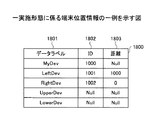
図18は、一実施形態に係る端末位置情報1800の一例を示す図である。図18は、図17の通信端末5f1で検知される位置情報の一例である。   FIG. 18 is a diagram showing an example of terminal location information 1800 according to an embodiment. FIG. 18 is an example of position information detected by the communication terminal 5f1 in FIG.

図18において、データラベル1801の列の「MyDev」は、自装置、すなわち、通信端末5f1を示す。データラベルの列の「LeftDev」は、自装置の左方向に位置する通信端末5f2を示す。データラベル1801の列の「RightDev」は、自装置の右方向に位置する通信端末5f3を示す。同様に、「UpperDev」、「LowerDev」は、それぞれ、図17では配置されていないが、上方向の通信端末、下方向の通信端末を示す。   In FIG. 18, “MyDev” in the column of the data label 1801 indicates the own device, that is, the communication terminal 5f1. “LeftDev” in the data label column indicates the communication terminal 5f2 located in the left direction of the own device. “RightDev” in the column of the data label 1801 indicates the communication terminal 5f3 located in the right direction of the own device. Similarly, “UpperDev” and “LowerDev” are not arranged in FIG. 17, but indicate an upward communication terminal and a downward communication terminal, respectively.

図18のID1802の列は、それぞれデータラベル1801に対応する通信端末のIDを示す。図17に示す配置の例では、通信端末5f1の左側に、端末IDが「1001」である通信端末5f2が配置されているので、LeftDevのID1802の行には、「1001」が挿入される。同様にして、RightDevのID1802の行には、通信端末5f3の端末ID「1002」が挿入される。また、図17の配置の例では、通信端末5f1の上方向及び下方向には、通信端末が配置されていない。この場合、UpperDev、LowerDevのID1802の行には、通信端末が配置されていないことを示す「Null」が挿入される。このように、図18のデータラベル1801の列、及びID1802の列の情報は、通信端末5f1(MyDrv)に対する他の通信端末5f2、5f3等の位置(方向)を示す。   Each column of ID 1802 in FIG. 18 indicates the ID of a communication terminal corresponding to the data label 1801. In the example of the arrangement illustrated in FIG. 17, the communication terminal 5f2 having the terminal ID “1001” is arranged on the left side of the communication terminal 5f1, and therefore “1001” is inserted in the row of the Left Dev ID 1802. Similarly, the terminal ID “1002” of the communication terminal 5f3 is inserted into the line of ID 1802 of RightDev. Moreover, in the example of arrangement | positioning of FIG. 17, the communication terminal is not arrange | positioned in the upward direction and downward direction of the communication terminal 5f1. In this case, “Null” indicating that no communication terminal is arranged is inserted in the row of ID 1802 of UpperDev and LowerDev. As described above, the information in the column of the data label 1801 and the column of the ID 1802 in FIG. 18 indicates the positions (directions) of the other communication terminals 5f2, 5f3, etc. with respect to the communication terminal 5f1 (MyDrv).

図18の距離1803の列は、自装置(MyDev)とデータラベル1801のそれぞれに対応する通信端末との距離を示す。図18の例では、「1000」のID1802を有する通信端末5f1(MyDev)と、通信端末5f1の左方向に隣接した「1001」のID1802を有する通信端末5f2(LeftDev)との距離が「1000」であることを示す。同様に、通信端末5f1と、通信端末5f1の右方向に隣接し、「1002」のID1802を有する通信端末5f2(RightDev)との距離が「0」であることを示す。尚、距離の単位は、システムの要求等に応じて、任意の単位を用いることができる。   The column of distance 1803 in FIG. 18 indicates the distance between the own device (MyDev) and the communication terminal corresponding to each of the data labels 1801. In the example of FIG. 18, the distance between the communication terminal 5f1 (MyDev) having the ID 1802 of “1000” and the communication terminal 5f2 (LeftDev) having the ID 1802 of “1001” adjacent to the left of the communication terminal 5f1 is “1000”. Indicates that Similarly, the distance between the communication terminal 5f1 and the communication terminal 5f2 (RightDev) adjacent to the communication terminal 5f1 in the right direction and having the ID 1802 of “1002” is “0”. It should be noted that any unit can be used as the unit of distance according to the requirements of the system.

また、通信端末5f1の上方向及び下方向には、通信端末が配置されていないので、UpperDev、LowerDevの距離1803の行には、通信端末が配置されていないことを示す「Null」が挿入される。このように、図18のID1802の列の情報は、通信端末5f1(MyDev)に対する他の通信端末の位置(距離)を示す。   In addition, since no communication terminal is arranged above and below the communication terminal 5f1, “Null” indicating that no communication terminal is arranged is inserted in the row of the distance 1803 of UpperDev and LowerDev. The Thus, the information in the column of ID 1802 in FIG. 18 indicates the position (distance) of another communication terminal with respect to the communication terminal 5f1 (MyDev).

このように、各通信端末5f1〜5f3は、自装置の上下左右に配置された、他の通信端末のID(識別情報)、及び他の通信端末と自装置との距離に関する情報を、例えば、図18に示す表構造のデータ(端末位置情報)として記憶する。また、各通信端末5f1〜5f3は、記憶した端末位置情報を、予め定められた端末管理システム7へ、送受信部51を介して送信する。   In this way, each communication terminal 5f1 to 5f3, for example, IDs (identification information) of other communication terminals arranged on the top, bottom, left, and right of the own device, and information on the distance between the other communication terminal and the own device, for example, It is stored as data (terminal position information) having a table structure shown in FIG. Further, each of the communication terminals 5f1 to 5f3 transmits the stored terminal position information to the predetermined terminal management system 7 via the transmission / reception unit 51.

(端末管理システムの機能構成)
続いて、図19を用いて、端末管理システム7の機能構成について説明する。図19は、端末管理システムの各機能を示す機能ブロック図である。
(Functional configuration of terminal management system)
Next, the functional configuration of the terminal management system 7 will be described with reference to FIG. FIG. 19 is a functional block diagram showing each function of the terminal management system.

図12に示されているように、端末管理システム7は、送受信部71a、送受信部71b、認証部75、及び位置情報管理部1901を有している。更に、端末管理システム7は、図9に示されているHDD204によって構築される記憶部7000を有している。この記憶部7000には、配信先選択メニューデータ、端末管理テーブル7010、利用可能端末管理テーブル7020、及び端末配置管理テーブル1902が記憶される。   As illustrated in FIG. 12, the terminal management system 7 includes a transmission / reception unit 71a, a transmission / reception unit 71b, an authentication unit 75, and a location information management unit 1901. Further, the terminal management system 7 has a storage unit 7000 constructed by the HDD 204 shown in FIG. The storage unit 7000 stores distribution destination selection menu data, a terminal management table 7010, an available terminal management table 7020, and a terminal arrangement management table 1902.

このうち、配信先選択メニューは、図20に示されているような配信先選択メニュー画面を示すデータである。   Among these, the delivery destination selection menu is data indicating a delivery destination selection menu screen as shown in FIG.

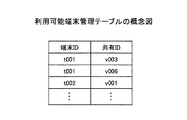
端末管理テーブル7010では、図21に示されているように、通信端末5の端末ID、ユーザ証明書、ユーザが配信システム1のサービスを利用する際の契約情報、通信端末5の端末種別、各通信端末5のホームURL(Uniform Resource Locator)を示す設定情報、各通信端末5の実行環境情報、共有ID、設置位置情報、及び表示名情報が関連付けて管理されている。このうち、実行環境情報には、各通信端末5の「お気に入り」、「前回のCookie情報」、及び「キャッシュファイル」が含まれており、各通信端末5のログイン後に、設定情報と共に配信制御システム2に送信され、各通信端末5に対して個別のサービスを行うために利用される。   In the terminal management table 7010, as shown in FIG. 21, the terminal ID of the communication terminal 5, the user certificate, the contract information when the user uses the service of the distribution system 1, the terminal type of the communication terminal 5, The setting information indicating the home URL (Uniform Resource Locator) of the communication terminal 5, the execution environment information, the shared ID, the installation position information, and the display name information of each communication terminal 5 are managed in association with each other. Among these, the execution environment information includes “favorites”, “previous cookie information”, and “cache file” of each communication terminal 5, and a distribution control system together with setting information after each communication terminal 5 logs in. 2 and used to provide individual services to each communication terminal 5.

また、共有IDは、各ユーザが、自己の通信端末5に配信されている映像(音)データと同じ内容の映像(音)データを他の通信端末5にも配信させることで、遠隔共有処理を行う場合に利用されるIDであり、他の通信端末又は他の通信端末群を識別する識別情報である。例えば、端末ID「t006」の共有IDは「v006」であり、端末ID「t007」の共有IDは「v006」であり、また、端末ID「t008」の共有IDは「v006」である。更に、端末ID「t001」の通信端末5aから、共有ID「v006」の通信端末(5f1,5f2,5f3)との遠隔共有処理の要求があった場合には、配信制御システム2は、通信端末(5f1,5f2,5f3)に対して、通信端末5aに配信中の映像(音)データと同じ映像(音)データを配信する。但し、通信端末5aと通信端末(5f1,5f2,5f3)の表示部58の解像度が異なる場合には、これに応じて、配信制御システム2が映像(音)データを配信する。   In addition, the sharing ID allows each user to distribute video (sound) data having the same content as the video (sound) data distributed to his / her communication terminal 5 to other communication terminals 5, thereby enabling remote sharing processing. This ID is used when performing the above, and is identification information for identifying another communication terminal or another communication terminal group. For example, the shared ID of the terminal ID “t006” is “v006”, the shared ID of the terminal ID “t007” is “v006”, and the shared ID of the terminal ID “t008” is “v006”. Furthermore, when there is a request for remote sharing processing from the communication terminal 5a with the terminal ID “t001” to the communication terminals (5f1, 5f2, 5f3) with the share ID “v006”, the distribution control system 2 For (5f1, 5f2, 5f3), the same video (sound) data as the video (sound) data being distributed is distributed to the communication terminal 5a. However, when the resolutions of the display units 58 of the communication terminal 5a and the communication terminals (5f1, 5f2, 5f3) are different, the distribution control system 2 distributes video (sound) data accordingly.

更に、設置位置情報は、例えば、図5に示されているように、通信端末(5f1,5f2,5f3)が並んで設置される場合の設置位置を示している。表示名情報は、図20に示されている配信先選択メニュー画面の表示名の内容を表す情報である。
一方、利用可能端末管理テーブル7020では、端末ID毎に、この端末IDによって示される通信端末5が遠隔共有処理することが可能な通信端末又は通信端末群を示す共有IDが関連付けて管理されている。
Furthermore, the installation position information indicates the installation position when the communication terminals (5f1, 5f2, 5f3) are installed side by side, for example, as shown in FIG. The display name information is information representing the contents of the display name on the distribution destination selection menu screen shown in FIG.
On the other hand, in the available terminal management table 7020, for each terminal ID, a shared ID indicating a communication terminal or a communication terminal group that can be remotely shared by the communication terminal 5 indicated by the terminal ID is managed in association with each other. .

図23は、一実施の形態に係る端末配置管理テーブル1902の一例を示す図である。端末配置管理テーブル1902には、端末ID2301、データラベル2302、ID2303、距離2304、及び配置位置2305等が記録されている。   FIG. 23 is a diagram showing an example of the terminal arrangement management table 1902 according to the embodiment. In the terminal arrangement management table 1902, a terminal ID 2301, a data label 2302, an ID 2303, a distance 2304, an arrangement position 2305, and the like are recorded.

次に、各機能構成について説明する。送受信部71aは、通信端末5との間で、各種データや要求等の送受信を行う。例えば、送受信部71aは、通信端末5の送受信部51からログイン要求を受信したり、送受信部51に対してログイン要求の認証結果を送信する。   Next, each functional configuration will be described. The transmission / reception unit 71 a transmits and receives various data and requests to and from the communication terminal 5. For example, the transmission / reception unit 71 a receives a login request from the transmission / reception unit 51 of the communication terminal 5 or transmits an authentication result of the login request to the transmission / reception unit 51.

送受信部71bは、配信制御システム2との間で、各種データや要求等の送受信を行う。例えば、送受信部71bは、配信制御システム2の送受信部21から配信先選択メニューのデータの要求を受信したり、送受信部21に対して、配信先選択メニューのデータを送信する。   The transmission / reception unit 71b transmits / receives various data and requests to / from the distribution control system 2. For example, the transmission / reception unit 71 b receives a request for data of a distribution destination selection menu from the transmission / reception unit 21 of the distribution control system 2 or transmits data of the distribution destination selection menu to the transmission / reception unit 21.

認証部75は、受信した端末ID及びユーザ証明書に基づいて、端末管理テーブル7010を検索することにより、同じ組み合わせの端末ID及びユーザ証明書があるか否かを判断することで、通信端末5aの認証を行う。   The authentication unit 75 searches the terminal management table 7010 based on the received terminal ID and user certificate, and determines whether there is a terminal ID and user certificate of the same combination, thereby determining the communication terminal 5a. Authenticate.

位置情報管理部1901は、各通信端末5から、端末位置情報を受信すると、送信元の通信端末5の端末ID2301に対応付けて、データラベル2302、ID2303、距離2304を端末配置管理テーブル1902に記録する。また、位置情報管理部1901は、受信した端末位置情報に基づいて、複数の通信端末5f1〜5f3の位置関係を特定し、配置位置2305に記録する。   Upon receiving the terminal location information from each communication terminal 5, the location information management unit 1901 records the data label 2302, ID 2303, and distance 2304 in the terminal arrangement management table 1902 in association with the terminal ID 2301 of the transmission source communication terminal 5. To do. In addition, the position information management unit 1901 specifies the positional relationship between the plurality of communication terminals 5f1 to 5f3 based on the received terminal position information, and records it in the arrangement position 2305.

例えば、図23に示す端末配置管理テーブル1902より、端末ID「1000」の通信端末(5f1)の左側に端末ID「1001」の通信端末(5f2)が配置されていることを読み取ることができる、また、端末ID「1000」の通信端末(5f1)の右側に端末ID「1002」の通信端末(5f3)が配置されていることを読取ることができる。さらに、端末ID「1000」の通信端末の上下方向には、通信端末が配置されていないことも判る。   For example, it can be read from the terminal arrangement management table 1902 shown in FIG. 23 that the communication terminal (5f2) with the terminal ID “1001” is arranged on the left side of the communication terminal (5f1) with the terminal ID “1000”. Further, it can be read that the communication terminal (5f3) with the terminal ID “1002” is arranged on the right side of the communication terminal (5f1) with the terminal ID “1000”. Further, it can also be seen that no communication terminal is arranged in the vertical direction of the communication terminal with the terminal ID “1000”.

同様にして、端末ID「1001」の通信端末の右側には、端末ID「1000」の通信端末が配置され、他の方向には、通信端末が配置されていないことを読取ることができる。さらに、端末ID「1002」の通信端末の左側には、端末ID「1000」の通信端末が配置され、他の方向には、通信端末が配置されていないことを読取ることができる。   Similarly, it can be read that the communication terminal with the terminal ID “1000” is arranged on the right side of the communication terminal with the terminal ID “1001” and no communication terminal is arranged in the other direction. Further, it can be read that the communication terminal with the terminal ID “1000” is arranged on the left side of the communication terminal with the terminal ID “1002” and no communication terminal is arranged in the other direction.

従って、位置情報管理部1901は、端末配置管理テーブル1902に記録された情報により、端末ID「1001」、「1000」、「1002」の通信端末が左から順番に横に並んでいることを特定することができる。   Therefore, the location information management unit 1901 specifies that the communication terminals with the terminal IDs “1001”, “1000”, and “1002” are arranged horizontally in order from the left based on the information recorded in the terminal arrangement management table 1902. can do.

<センサ部の構成>
ここで、通信端末5のセンサ部1603の具体的な構成について説明する。
<Configuration of sensor unit>
Here, a specific configuration of the sensor unit 1603 of the communication terminal 5 will be described.

[第1の実施の形態]
図24は、第1の実施形態に係るセンサ部1603の構成例を示す図である。図24(a)において、通信端末5の右側及び左側の辺には、カメラとバーコードが一体となったセンサ部1603A及び1603Bが、略同じ高さとなるように装着されている。センサ部1603Aのカメラ2401の対物レンズ、及びバーコード2402は、通信端末5の端面から外側を向いて設置されている。また、センサ部1603B、カメラ2404の対物レンズ、及びバーコード2403は、通信端末5の端面から外側を向いて設置されている。
[First Embodiment]
FIG. 24 is a diagram illustrating a configuration example of the sensor unit 1603 according to the first embodiment. In FIG. 24A, sensor units 1603A and 1603B, in which the camera and the barcode are integrated, are mounted on the right and left sides of the communication terminal 5 so as to have substantially the same height. The objective lens of the camera 2401 of the sensor unit 1603 </ b> A and the barcode 2402 are installed facing outward from the end face of the communication terminal 5. In addition, the sensor unit 1603 </ b> B, the objective lens of the camera 2404, and the barcode 2403 are installed facing outward from the end face of the communication terminal 5.

図24(b)は、センサ部1603Aを、図24(a)の矢印2405の方向から見た図である。センサ部1603Aは、上側にカメラ2401が、下側にバーコード2402が配置されている。また、バーコード2402には、通信端末5の端末ID等の識別情報がバーコード化されて印刷されている。尚、バーコード2402は、通信端末5の識別情報を示す識別コードの一例である。バーコード2402は、例えば、QRコード(登録商標)等の他の識別コードであっても良い。   FIG. 24B is a diagram of the sensor unit 1603A viewed from the direction of the arrow 2405 in FIG. In the sensor unit 1603A, a camera 2401 is disposed on the upper side and a barcode 2402 is disposed on the lower side. In the barcode 2402, identification information such as the terminal ID of the communication terminal 5 is printed as a barcode. The bar code 2402 is an example of an identification code indicating identification information of the communication terminal 5. The barcode 2402 may be another identification code such as a QR code (registered trademark), for example.

図24(c)は、センサ部1603Bを、図24の矢印2406の方向から見た図である。センサ部1603Bは、上側にバーコード2403が、下側にカメラ2404が配置されている。また、バーコード2403には、通信端末5の端末ID等の識別情報がコード化されて印刷されている。このように、センサ部1603Aとセンサ部1603Bは、カメラとバーコードが対称な配置となっている。これにより、例えば、通信端末5の右側、又は左側に他の通信端末5を、上下方向の位置を合わせて隣接配置した場合、通信端末5のカメラと、隣接配置した他の通信端末5のバーコードとが対向するように構成されている。   FIG. 24C is a diagram of the sensor unit 1603B viewed from the direction of the arrow 2406 in FIG. In the sensor unit 1603B, a barcode 2403 is disposed on the upper side, and a camera 2404 is disposed on the lower side. In the bar code 2403, identification information such as the terminal ID of the communication terminal 5 is encoded and printed. Thus, the sensor unit 1603A and the sensor unit 1603B are arranged so that the camera and the barcode are symmetrical. Thereby, for example, when another communication terminal 5 is arranged adjacent to the right or left side of the communication terminal 5 with the vertical position aligned, the camera of the communication terminal 5 and the bar of the other communication terminal 5 arranged adjacent to each other are arranged. The cord is configured to face the cord.

同様にして、図24(a)に示すように、通信端末5の上側の辺及び下側の辺には、それぞれセンサ部1603C及びセンサ部1603Dが、それぞれ左右方向で同じ位置になうように設置されている。さらに、センサ部1603Cとセンサ部1603Dは、カメラとバーコードの位置が対称な配置となっている。これにより、例えば、通信端末5の上側、又は下側に他の通信端末5を、左右方向の位置を合わせて隣接配置した場合、通信端末5のカメラと隣接配置した他の通信端末5のバーコードとが対向するように構成されている。   Similarly, as shown in FIG. 24A, the sensor unit 1603C and the sensor unit 1603D are respectively located in the same position in the left-right direction on the upper side and the lower side of the communication terminal 5, respectively. is set up. Furthermore, the sensor unit 1603C and the sensor unit 1603D are arranged so that the positions of the camera and the barcode are symmetrical. Thereby, for example, when another communication terminal 5 is arranged adjacent to the upper side or the lower side of the communication terminal 5 in the left-right direction, the bar of the other communication terminal 5 arranged adjacent to the camera of the communication terminal 5 is arranged. The cord is configured to face the cord.

また、好ましくは、図24(a)のセンサ部1603A〜Dの各カメラ(撮像手段)は、オートフォーカス機能を搭載し、合焦したとき(焦点が合ったとき)の距離情報を図16の制御部1601へ出力する。出力された距離情報は、制御部1601により、図18の端末位置情報1800の距離1803の列の情報として、図16の一次記憶部1602に記憶される。尚、距離情報は、各カメラから出力されたデータ又は情報に基づいて、制御部1601が算出するものであっても良い。   Preferably, each camera (imaging means) of the sensor units 1603A to 1603D in FIG. 24A is equipped with an autofocus function, and distance information when focused (when focused) is shown in FIG. The data is output to the control unit 1601. The output distance information is stored in the primary storage unit 1602 of FIG. 16 by the control unit 1601 as information in the column of the distance 1803 of the terminal position information 1800 of FIG. The distance information may be calculated by the control unit 1601 based on data or information output from each camera.

上記構成により、他の通信端末の端末IDと、他の通信端末との距離とを同時に検知する仕組みを安価に構成することができる。また、近接時の混信の恐れが少ないので、信頼性を高めることができる。   With the above configuration, a mechanism for simultaneously detecting the terminal ID of another communication terminal and the distance from the other communication terminal can be configured at low cost. In addition, since there is little risk of interference when approaching, reliability can be improved.

尚、カメラとバーコードが一体となったセンサ部1603は一例であって、カメラとバーコードは、別々に設けられていても良い。   Note that the sensor unit 1603 in which the camera and the barcode are integrated is an example, and the camera and the barcode may be provided separately.

[第2の実施形態]
図25は、第2の実施形態に係るセンサ部1603の構成例を示す図である。図25(a)において、通信端末5の右側及び左側の辺には、ICカードリーダとICカードが一体となったセンサ部1603A及び1603Bが、略同じ高さとなるように設けられている。センサ部1603AのICカードリーダ(ICタグリーダ)2501の読み取り面、及びICカード(ICタグ)2502は、通信端末5の端面から外側を向いて設置されている。また、センサ部1603BのICカードリーダ2504の読み取り面、及びICカード2503は、通信端末5の端面から外側を向いて設置されている。
[Second Embodiment]
FIG. 25 is a diagram illustrating a configuration example of the sensor unit 1603 according to the second embodiment. In FIG. 25A, sensor units 1603A and 1603B in which an IC card reader and an IC card are integrated are provided on the right and left sides of the communication terminal 5 so as to have substantially the same height. The reading surface of the IC card reader (IC tag reader) 2501 of the sensor unit 1603A and the IC card (IC tag) 2502 are installed facing outward from the end surface of the communication terminal 5. Further, the reading surface of the IC card reader 2504 of the sensor unit 1603B and the IC card 2503 are installed facing outward from the end surface of the communication terminal 5.

図25(b)は、センサ部1603Aを、図25(a)の矢印2505の方向から見た図である。センサ部1603Aは、上側にICカードリーダ2501が、下側にICカード2502が配置されている。また、ICカード2502には、通信端末5の端末ID等の識別情報がコード化されて格納されている。   FIG. 25B is a diagram of the sensor unit 1603A viewed from the direction of the arrow 2505 in FIG. The sensor unit 1603A has an IC card reader 2501 on the upper side and an IC card 2502 on the lower side. Further, identification information such as a terminal ID of the communication terminal 5 is encoded and stored in the IC card 2502.

図24(c)は、センサ部1603Bを、図25の矢印2506の方向から見た図である。センサ部1603Bは、上側にICカード2503が、下側にICカードリーダ2504が配置されている。また、ICカード2503には、通信端末5の端末ID等の識別情報がコード化されて格納されている。このように、センサ部1603Aとセンサ部1603Bは、ICカードとICカードリーダが対称な配置となっている。これにより、例えば、通信端末5の右側、又は左側に他の通信端末5を上下方向の位置を合わせて隣接配置した場合、通信端末5のICカードリーダと、隣接配置させた他の通信端末5のICカードとが対向するように構成されている。   FIG. 24C is a diagram of the sensor unit 1603B viewed from the direction of the arrow 2506 in FIG. The sensor unit 1603B has an IC card 2503 on the upper side and an IC card reader 2504 on the lower side. Further, identification information such as the terminal ID of the communication terminal 5 is encoded and stored in the IC card 2503. As described above, the sensor unit 1603A and the sensor unit 1603B are arranged so that the IC card and the IC card reader are symmetrical. Thereby, for example, when another communication terminal 5 is arranged adjacent to the right side or the left side of the communication terminal 5 in the vertical direction, the IC card reader of the communication terminal 5 and the other communication terminal 5 arranged adjacent to each other. The IC card is configured to face the IC card.

同様にして、図25(a)に示すように、通信端末5の上側の辺及び下側の辺には、それぞれセンサ部1603C及びセンサ部1603Dが、それぞれ左右方向で同じ位置になうように設置されている。さらに、センサ部1603Cとセンサ部1603Dは、ICカードとICカードリーダの位置が対称な配置となっている。これにより、例えば、通信端末5の上側、又は下側に他の通信端末5を、左右方向の位置を合わせて隣接配置させた場合、通信端末5のICカードリーダと隣接配置させた他の通信端末5のICカードとが対向するように構成されている。   Similarly, as shown in FIG. 25A, the sensor unit 1603C and the sensor unit 1603D are respectively located at the same position in the left-right direction on the upper side and the lower side of the communication terminal 5, respectively. is set up. Further, the sensor unit 1603C and the sensor unit 1603D are arranged so that the positions of the IC card and the IC card reader are symmetrical. Thereby, for example, when another communication terminal 5 is arranged adjacent to the upper side or the lower side of the communication terminal 5 in the left-right direction, the other communication arranged adjacent to the IC card reader of the communication terminal 5 The terminal 5 is configured to face the IC card.

本実施の形態に係る通信端末5f1のICカードリーダは、隣接配置された通信端末5f2のICカードから、通信端末5f2の端末IDを非接触で読み取り可能である。例えば、ICカードリーダは、所定の到達距離の磁界を発生しており、ICカードがこの磁界を通過するとICカード内部のコイルが磁界を受けて電流を発生する。そして、ICカードに埋め込まれたIC(集積回路)がこの電流を利用してICカードリーダと通信を行う。   The IC card reader of the communication terminal 5f1 according to the present embodiment can read the terminal ID of the communication terminal 5f2 in a non-contact manner from the IC card of the communication terminal 5f2 arranged adjacently. For example, an IC card reader generates a magnetic field of a predetermined reach distance, and when the IC card passes this magnetic field, a coil inside the IC card receives the magnetic field and generates a current. Then, an IC (integrated circuit) embedded in the IC card uses this current to communicate with the IC card reader.

ICカードの具体的な例として、例えば、Felica(登録商標)、NFC(Near Field Communication)、密着型のRFID(Radio Frequency Identification)タグ等がある。また、ICカードは、他の近距離無線通信方式等により識別情報を通信するものであっても良い。尚、ICカードは、ICタグの一例である。ICタグは、例えば、半導体チップや、モジュール等、カード以外の形状であっても良い。   Specific examples of the IC card include, for example, Felica (registered trademark), NFC (Near Field Communication), and a close-contact RFID (Radio Frequency Identification) tag. Further, the IC card may communicate identification information by another short-range wireless communication method or the like. The IC card is an example of an IC tag. The IC tag may have a shape other than a card, such as a semiconductor chip or a module.

また、本実施の形態では、通信端末5f1と隣接配置された他の通信端末5f2、5f3等の外装カバー同士が接触する程度(例えば、5mm以下)で互いを検知できるように、ICカード及び/又はICカードリーダのアンテナ感度等が調整されている。従って、本実施の形態に係る通信端末5f1は、隣接して配置された他の通信端末5f2、5f3等との距離が所定の範囲内(例えば、5mm以下)である場合に、端末位置情報を検知する。   In the present embodiment, the IC card and / or the communication terminal 5f1 can be detected so that the exterior covers of the other communication terminals 5f2, 5f3, etc. arranged adjacent to each other are in contact with each other (for example, 5 mm or less). Alternatively, the antenna sensitivity of the IC card reader is adjusted. Therefore, the communication terminal 5f1 according to the present embodiment displays the terminal position information when the distance from the other communication terminals 5f2, 5f3, etc. arranged adjacent to each other is within a predetermined range (for example, 5 mm or less). Detect.

上記構成によれば、近接設置された他の通信端末の端末IDを取得する仕組みを、従来からある技術を利用して、安価に構成することができる。また、接触する程度まで近づけたときに端末IDを検出するので、自由度は低いが信頼性が高い。   According to the said structure, the mechanism which acquires terminal ID of the other communication terminal installed in proximity | contact can be comprised cheaply using a conventional technique. Further, since the terminal ID is detected when the contact is brought close to the contact level, the degree of freedom is low but the reliability is high.

尚、本構成では、通信端末5f1は隣接して配置された他の通信端末5f2との間の距離を特定することが困難である。そのため、通信端末5f1の制御部1601は、センサ部1603が、隣接して配置された他の通信端末5f2を検知すると、図18の端末位置情報1800の距離1803を、例えば、「0」として、記憶する。また、通信端末5f1の制御部1601は、センサ部1603が、隣接して配置された他の通信端末5f2を検知できない場合、図18の端末位置情報1800の距離1803を、例えば、「NULL」として記憶する。これにより、通信端末5f1は、所定の位置に近接配置された他の通信端末5f2、5f3等の有無、位置(上下左右)、及び識別情報(端末ID)等を取得することができる。   In this configuration, it is difficult to specify the distance between the communication terminal 5f1 and another communication terminal 5f2 arranged adjacent to the communication terminal 5f1. Therefore, when the sensor unit 1603 detects another communication terminal 5f2 arranged adjacent to the control unit 1601 of the communication terminal 5f1, the distance 1803 of the terminal position information 1800 in FIG. 18 is set to “0”, for example. Remember. In addition, when the sensor unit 1603 cannot detect another communication terminal 5f2 disposed adjacent to the control unit 1601 of the communication terminal 5f1, the distance 1803 of the terminal position information 1800 in FIG. 18 is set to “NULL”, for example. Remember. Thereby, the communication terminal 5f1 can acquire the presence / absence, position (up / down / left / right) of other communication terminals 5f2, 5f3, and the like, which are arranged close to a predetermined position, and identification information (terminal ID).

尚、ICカードリーダ(ICタグリーダ)とICカード(ICタグ)が一体となったセンサ部1603は一例であって、ICカードリーダとICカードは、別々に設けられていても良い。   Note that the sensor unit 1603 in which an IC card reader (IC tag reader) and an IC card (IC tag) are integrated is an example, and the IC card reader and the IC card may be provided separately.

図26は、一実施形態に係る複数の通信端末の配置の一例である。図26の例では、通信端末5f1の左側に通信端末5f2が、右側に通信端末5f3が、上側に通信端末5f4が、下側に通信端末5f5が隣接配置されている。このように、通信端末5f1〜5f5は、並べて配置した場合に、バーコード又はICカード等の端末ID保持部2602と、カメラ又はICカードリーダ等のID読み取り部2601と、の位置が互いに対向するように構成されている。   FIG. 26 is an example of an arrangement of a plurality of communication terminals according to an embodiment. In the example of FIG. 26, the communication terminal 5f2 is arranged on the left side of the communication terminal 5f1, the communication terminal 5f3 on the right side, the communication terminal 5f4 on the upper side, and the communication terminal 5f5 on the lower side. As described above, when the communication terminals 5f1 to 5f5 are arranged side by side, the positions of the terminal ID holding unit 2602 such as a barcode or an IC card and the ID reading unit 2601 such as a camera or an IC card reader face each other. It is configured as follows.

[第3の実施形態]
図27は、第3の実施形態に係るセンサ部1603の構成例を示す図である。図27(a)において、通信端末5の右側の辺及び左側の辺には、赤外線受信素子と、赤外線送信素子が一体となったセンサ部1603A及び1603Bが、略同じ高さとなるように設けられている。また、センサ部1603Aの赤外線受信素子2701、及び赤外線送信素子2702は、通信端末5の端面から外側を向いて設置されている。また、センサ部1603Bの赤外線受信素子2704、及び赤外線送信素子2703は、通信端末5の端面から外側を向いて設置されている。
[Third Embodiment]
FIG. 27 is a diagram illustrating a configuration example of the sensor unit 1603 according to the third embodiment. In FIG. 27A, the right side and the left side of the communication terminal 5 are provided with sensor portions 1603A and 1603B in which the infrared receiving element and the infrared transmitting element are integrated so as to have substantially the same height. ing. Further, the infrared receiving element 2701 and the infrared transmitting element 2702 of the sensor unit 1603 </ b> A are installed facing outward from the end face of the communication terminal 5. Further, the infrared receiving element 2704 and the infrared transmitting element 2703 of the sensor unit 1603B are installed facing outward from the end face of the communication terminal 5.

尚、赤外線受信素子2701、2704は、例えば、フォトダイオード、フォトトランジスタ、又はフォトIC(Integrated Circuit)等の光検出素子を含む。また、赤外線送信素子2702、2703は、例えば、発光ダイオード等の発光素子を含む。   The infrared receiving elements 2701 and 2704 include, for example, light detection elements such as photodiodes, phototransistors, or photo ICs (Integrated Circuits). The infrared transmission elements 2702 and 2703 include, for example, light emitting elements such as light emitting diodes.

赤外線受信素子および赤外線送信素子は、例えば、IrDA(Infrared Data Association)規格のハードウェア、通信モジュール等を好適に利用することができる。また、赤外線は一例であって、例えば、可視光線や紫外線等を含む光を用いるもの等であっても良い。   For example, IrDA (Infrared Data Association) standard hardware, a communication module, and the like can be suitably used for the infrared receiving element and the infrared transmitting element. Infrared rays are examples, and for example, those using light including visible light, ultraviolet rays, and the like may be used.

図27(b)は、センサ部1603Aを、図27(a)の矢印2705の方向から見た図である。センサ部1603Aは、上側に赤外線受信素子2701が、下側に赤外線送信素子2702が配置されている。赤外線送信素子2702からは、例えば、通信端末5の端末ID等の識別情報が送信される。   FIG. 27B is a diagram of the sensor unit 1603A viewed from the direction of the arrow 2705 in FIG. In the sensor unit 1603A, an infrared receiving element 2701 is disposed on the upper side, and an infrared transmitting element 2702 is disposed on the lower side. For example, identification information such as a terminal ID of the communication terminal 5 is transmitted from the infrared transmission element 2702.

図27(c)は、センサ部1603Bを、図25の矢印2706の方向から見た図である。センサ部1603Bは、上側に赤外線送信素子2703が、下側に赤外線受信素子2704が配置されている。赤外線送信素子2703からは、例えば、例えば、通信端末5の端末ID等の識別情報が送信される。   FIG. 27C is a diagram of the sensor unit 1603B viewed from the direction of the arrow 2706 in FIG. In the sensor unit 1603B, an infrared transmission element 2703 is disposed on the upper side, and an infrared reception element 2704 is disposed on the lower side. For example, identification information such as a terminal ID of the communication terminal 5 is transmitted from the infrared transmission element 2703.

このように、センサ部1603Aとセンサ部1603Bは、赤外線送信素子と赤外線受信素子が対称な配置となっている。これにより、例えば、通信端末5の右側、又は左側に他の通信端末5を上下方向の位置を合わせて隣接配置させた場合、通信端末5の赤外線受信素子と、隣接配置させた他の通信端末5の赤外線送信素子とが対向するように構成されている。   As described above, the sensor unit 1603A and the sensor unit 1603B are arranged such that the infrared transmitting element and the infrared receiving element are symmetrical. Thereby, for example, when another communication terminal 5 is arranged adjacent to the right or left side of the communication terminal 5 in the vertical direction, the infrared receiving element of the communication terminal 5 and another communication terminal arranged adjacent to each other are arranged. 5 is configured to face the infrared transmitting element.

同様にして、図27(a)に示すように、通信端末5の上側の辺及び下側の辺には、それぞれ、センサ部1603C及びセンサ部1603Dが、それぞれ左右方向で同じ位置になうように設置されている。さらに、センサ部1603Cとセンサ部1603Dは、赤外線送信素子と赤外線受信素子が対称な配置となっている。これにより、例えば、通信端末5の上側、又は下側に他の通信端末5を、左右方向の位置を合わせて隣接配置させた場合、通信端末5の赤外線受信素子と隣接配置させた他の通信端末5の赤外線送信素子とが対向するように構成されている。   Similarly, as shown in FIG. 27A, the sensor unit 1603C and the sensor unit 1603D are respectively located at the same position in the left-right direction on the upper side and the lower side of the communication terminal 5, respectively. Is installed. Further, in the sensor unit 1603C and the sensor unit 1603D, the infrared transmission element and the infrared reception element are arranged symmetrically. Thereby, for example, when another communication terminal 5 is arranged adjacent to the upper side or the lower side of the communication terminal 5 in the left-right direction, the other communication arranged adjacent to the infrared receiving element of the communication terminal 5 The terminal 5 is configured to face the infrared transmission element.

上記構成によれば、通信端末5と、隣接設置された他の通信端末5との間の距離が所定の距離以下となると、赤外線通信が確立され、互いの識別情報が交換される。また、本構成によれば、カメラやICカードによる構成と比べて、安価かつ堅牢にセンサ部1603を構成することができる。   According to the said structure, when the distance between the communication terminal 5 and the other communication terminal 5 installed adjacently becomes below a predetermined distance, infrared communication will be established and mutual identification information will be exchanged. Further, according to this configuration, the sensor unit 1603 can be configured cheaply and robustly compared to the configuration using a camera or an IC card.

尚、本構成では、通信端末5f1は隣接して配置された他の通信端末5f2との間の距離を特定することが困難である。そのため、通信端末5f1の制御部1601は、センサ部1603が、隣接して配置された他の通信端末5f2を検知すると、図18の端末位置情報1800の距離1803を、例えば、「0」として、記憶する。また、通信端末5f1の制御部1601は、センサ部1603が、隣接して配置された他の通信端末5f2を検知できない場合、図18の端末位置情報1800の距離1803を、例えば、「NULL」として記憶する。これにより、通信端末5f1は、所定の位置に近接配置された他の通信端末5f2、5f3の有無、位置(上下左右)、及び識別情報(端末ID)等を取得することができる。   In this configuration, it is difficult to specify the distance between the communication terminal 5f1 and another communication terminal 5f2 arranged adjacent to the communication terminal 5f1. Therefore, when the sensor unit 1603 detects another communication terminal 5f2 arranged adjacent to the control unit 1601 of the communication terminal 5f1, the distance 1803 of the terminal position information 1800 in FIG. 18 is set to “0”, for example. Remember. In addition, when the sensor unit 1603 cannot detect another communication terminal 5f2 disposed adjacent to the control unit 1601 of the communication terminal 5f1, the distance 1803 of the terminal position information 1800 in FIG. 18 is set to “NULL”, for example. Remember. As a result, the communication terminal 5f1 can acquire the presence / absence, position (up / down / left / right), identification information (terminal ID), and the like of the other communication terminals 5f2, 5f3 arranged close to a predetermined position.

尚、赤外線受信素子と赤外線送信素子が一体となったセンサ部1603は一例であって、赤外線受信素子と赤外線送信素子は、別々に設けられていても良い。   The sensor unit 1603 in which the infrared receiving element and the infrared transmitting element are integrated is an example, and the infrared receiving element and the infrared transmitting element may be provided separately.

[第4の実施形態]
図28は、第4の実施形態に係るセンサ部の構成例を示す図である。本実施形態では、第3の実施形態のセンサ部1603A、及びセンサ部1603Bの送受信面が、通信端末5f1、5f2の設置床面2801の法線、又はセンサ部が設けられた辺等に対して、所定の角度θだけ傾けて設けられている。
[Fourth Embodiment]
FIG. 28 is a diagram illustrating a configuration example of a sensor unit according to the fourth embodiment. In the present embodiment, the transmission / reception surfaces of the sensor unit 1603A and the sensor unit 1603B of the third embodiment are normal to the installation floor 2801 of the communication terminals 5f1 and 5f2, or the side where the sensor unit is provided. Inclined by a predetermined angle θ.

例えば、センサ部1603Aの赤外線受信素子(受光素子)2701の受信(受光)方向、及び/又は赤外線送信素子(発光素子)2702の送信(発光)方向に対応する面を送受信面2805Aとする。この場合、センサ部1603Aの送受信面2805Aは、設置床面2801の法線2802B、又は通信端末5f1のセンサ部1603Aに対応する辺2803に対して、所定の角度θだけ上向きに傾けて設けられている。   For example, a surface corresponding to the reception (light reception) direction of the infrared receiving element (light receiving element) 2701 and / or the transmission (light emitting) direction of the infrared transmission element (light emitting element) 2702 of the sensor unit 1603A is defined as a transmission / reception surface 2805A. In this case, the transmission / reception surface 2805A of the sensor unit 1603A is provided to be inclined upward by a predetermined angle θ with respect to the normal 2802B of the installation floor 2801 or the side 2803 corresponding to the sensor unit 1603A of the communication terminal 5f1. Yes.

また、センサ部1603Bの赤外線受信素子2704の受信方向、及び/又は赤外線送信素子2703の送信方向に対応する面を送受信面2805Bとする。この場合、センサ部1603Bの送受信面2805Bは、設置床面2801の法線2802A、又は通信端末5f1のセンサ部1603Bに対応する辺2804に対して、所定の角度θだけ下向きに傾けて設けられている。尚、通信端末5f2(他の通信端末)は、通信端末5f1と同様の構成を有しているものとする。   In addition, a surface corresponding to the reception direction of the infrared reception element 2704 and / or the transmission direction of the infrared transmission element 2703 of the sensor unit 1603B is referred to as a transmission / reception surface 2805B. In this case, the transmission / reception surface 2805B of the sensor unit 1603B is provided to be inclined downward by a predetermined angle θ with respect to the normal 2802A of the installation floor 2801 or the side 2804 corresponding to the sensor unit 1603B of the communication terminal 5f1. Yes. Note that the communication terminal 5f2 (another communication terminal) has the same configuration as the communication terminal 5f1.

さらに、通信端末5f1は、図8に示すように、設置床面2801に通信端末5f2と同じ向きで横に隣接配置したときに、通信端末5f1のセンサ部1603Aの送受信方向と、通信端末5f2のセンサ部1603Bの送受信方向が略一致するように構成されている。つまり、通信端末5f1のセンサ部1603Aの送受信面2805Aと、通信端末5f2のセンサ部1603Bの送受信面2805Bとが対向するように構成されている。   Further, as shown in FIG. 8, when the communication terminal 5f1 is disposed horizontally adjacent to the installation floor 2801 in the same direction as the communication terminal 5f2, the transmission / reception direction of the sensor unit 1603A of the communication terminal 5f1 and the communication terminal 5f2 The transmission / reception directions of the sensor unit 1603B are configured to substantially match. That is, the transmission / reception surface 2805A of the sensor unit 1603A of the communication terminal 5f1 and the transmission / reception surface 2805B of the sensor unit 1603B of the communication terminal 5f2 are configured to face each other.

図29は、第4の実施形態に係るセンサ部の配置例を示す図である。図29に示すように、各通信端末5f1〜5f3のセンサ部1603Aと、センサ部1603Bは、横に隣接して配置したときに、センサ部1603Aと、センサ部1603Bの送受信方向が略一致するように、縦方向に所定の距離dだけずらして配置されている。   FIG. 29 is a diagram illustrating an arrangement example of the sensor units according to the fourth embodiment. As shown in FIG. 29, when the sensor unit 1603A and the sensor unit 1603B of each of the communication terminals 5f1 to 5f3 are arranged adjacent to each other, the transmission / reception directions of the sensor unit 1603A and the sensor unit 1603B are substantially the same. Further, they are shifted in the vertical direction by a predetermined distance d.

この所定の距離dと、所定の角度θとにより、図29のように3台の通信端末5f1〜5f3を横に並べて配置したとき、通信端末5f1のセンサ部1603Aは、通信端末5f2のセンサ部1603Bと対向し、通信が可能である。一方、通信端末5f1のセンサ部1603Aは、通信端末5f3のセンサ部1603Bと対向せず、通信が困難である。   When the three communication terminals 5f1 to 5f3 are arranged side by side by the predetermined distance d and the predetermined angle θ, the sensor unit 1603A of the communication terminal 5f1 is the sensor unit of the communication terminal 5f2. Opposite to 1603B, communication is possible. On the other hand, the sensor unit 1603A of the communication terminal 5f1 does not face the sensor unit 1603B of the communication terminal 5f3, and communication is difficult.

このように、通信端末5f1〜5f3は、この所定の距離dと、所定の角度θの値により、隣接する通信端末を認識できる距離を調整することができる。   As described above, the communication terminals 5f1 to 5f3 can adjust the distance at which adjacent communication terminals can be recognized by the predetermined distance d and the value of the predetermined angle θ.

尚、図28及び29の構成はあくまで一例である。例えば、通信端末5f1〜5f3のセンサ部1603Aが所定の角度θだけ下向きに、また、センサ部1603Bが所定の角度θだけ上向きに設けられているものであっても良い。この場合、各通信端末5f1〜5f3のセンサ部1603Aと、センサ部1603Bは、横に隣接して配置したときに、センサ部1603Aと、センサ部1603Bの送受信方向が略一致するように、縦方向に所定の距離dだけ逆にずらして配置する。   28 and 29 are merely examples. For example, the sensor unit 1603A of the communication terminals 5f1 to 5f3 may be provided downward by a predetermined angle θ, and the sensor unit 1603B may be provided upward by a predetermined angle θ. In this case, the sensor unit 1603A and the sensor unit 1603B of each of the communication terminals 5f1 to 5f3 are arranged in the vertical direction so that the transmission / reception directions of the sensor unit 1603A and the sensor unit 1603B substantially coincide with each other when arranged adjacent to each other. Are shifted by a predetermined distance d.

尚、所定の角度θの値は、例えば、センサ部1603の赤外線送信素子の送信可能な角度である発光範囲、及び/又は赤外線受信素子の受信可能な角度である受光範囲等に応じて適切な値を設定する。或いは、所定の角度θに合わせて、後述する遮光板や、集光レンズを用いて、上記発光範囲、及び/又は受光範囲を設定するものであっても良い。   Note that the value of the predetermined angle θ is appropriate depending on, for example, the light emission range that is the transmittable angle of the infrared transmitting element of the sensor unit 1603 and / or the light receiving range that is the receivable angle of the infrared receiving element. Set the value. Alternatively, the light emitting range and / or the light receiving range may be set using a light shielding plate or a condenser lens, which will be described later, in accordance with a predetermined angle θ.

いずれの場合でも、所定の角度θの値が±90°を超えると赤外通信が困難となるので、所定の角度θは、0°<θ<±90°の範囲内で設定することが望ましい。   In any case, if the value of the predetermined angle θ exceeds ± 90 °, infrared communication becomes difficult. Therefore, it is desirable to set the predetermined angle θ within a range of 0 ° <θ <± 90 °. .

[第5の実施形態]
図30は、第5の実施形態に係るセンサ部の構成例を示す図である。本実施形態に係る通信端末5f1は、第4の実施形態に係るセンサ部1603A、1603Bの送信方向及び/又は受信方向に、光(赤外線)の指向性を制限する(狭める)ための遮光板を有している。
[Fifth Embodiment]
FIG. 30 is a diagram illustrating a configuration example of a sensor unit according to the fifth embodiment. The communication terminal 5f1 according to the present embodiment includes a light shielding plate for limiting (narrowing) the directivity of light (infrared rays) in the transmission direction and / or the reception direction of the sensor units 1603A and 1603B according to the fourth embodiment. Have.

例えば、図30において、センサ部1603Aの赤外線受信素子(受光素子)2701の受信方向には、遮光板3001A、3001Bが設けられている。この遮光板3001A、3001Bにより、赤外線受信素子2701が光を受信可能な角度である受光範囲が制限されている。また、赤外線送信素子2702の送信方向には、遮光板3001C、3001Dが設けられている。この遮光板3001C、3001Dにより、赤外線送信素子(発光素子)2703が光を送信可能な角度である発光範囲が制限されている。   For example, in FIG. 30, light shielding plates 3001A and 3001B are provided in the receiving direction of the infrared receiving element (light receiving element) 2701 of the sensor unit 1603A. The light receiving range that is an angle at which the infrared receiving element 2701 can receive light is limited by the light shielding plates 3001A and 3001B. Further, light shielding plates 3001C and 3001D are provided in the transmission direction of the infrared transmission element 2702. The light-shielding plates 3001 </ b> C and 3001 </ b> D limit a light emission range that is an angle at which the infrared transmission element (light-emitting element) 2703 can transmit light.

同様に、センサ部1603Bの赤外線送信素子2703の送信方向には、遮光板3001E、3001Fが設けられており、赤外線受信素子2704の受信方向には、遮光板3001G、3001Hが設けられている。   Similarly, light shielding plates 3001E and 3001F are provided in the transmission direction of the infrared transmission element 2703 of the sensor unit 1603B, and light shielding plates 3001G and 3001H are provided in the reception direction of the infrared reception element 2704.

上記構成により、通信端末5f1が、横方向に隣接して配置された他の通信端末5f2、5f3を検知できる距離の幅を制限することや、誤動作を低減させること等が可能となる。   With the above configuration, the communication terminal 5f1 can limit the distance width in which the other communication terminals 5f2 and 5f3 arranged adjacent to each other in the lateral direction can be limited, reduce malfunctions, and the like.

尚、図30の構成は一例であって、本発明の範囲を限定するものではない。例えば、赤外線受信素子2701の受信方向に設けられた遮光板3001Aと遮光板3001Bは、必ずしも対称でなくても良い。例えば、システムの要求や用途等に応じて、遮光板3001Aと遮光板3001Bの長さ、角度等が異なっていても良い。他の遮光板3001C〜3001Hについても同様である。   30 is merely an example, and does not limit the scope of the present invention. For example, the light shielding plate 3001A and the light shielding plate 3001B provided in the receiving direction of the infrared receiving element 2701 do not necessarily have to be symmetrical. For example, the length, angle, and the like of the light shielding plate 3001A and the light shielding plate 3001B may be different depending on the requirements and applications of the system. The same applies to the other light shielding plates 3001C to 3001H.

また、遮光板3001C、3001D、3001E、3001Fは、送信する光(赤外線)の指向性を制限するための遮光面の一例である。また、遮光板3001A、3001B、3001G、3001Hは、受信する光(赤外線)の指向性を制限するための遮光面の一例である。例えば、遮光板3001A〜3001Dは、送信する光、及び受信する光の指向性を制限する遮光面を有していれば、他の形状であっても良い。   The light shielding plates 3001C, 3001D, 3001E, and 3001F are examples of light shielding surfaces for limiting the directivity of light (infrared rays) to be transmitted. The light shielding plates 3001A, 3001B, 3001G, and 3001H are examples of light shielding surfaces for limiting the directivity of received light (infrared rays). For example, the light shielding plates 3001A to 3001D may have other shapes as long as they have a light shielding surface that restricts the directivity of light to be transmitted and light to be received.

[第6の実施形態]
図31は、第6の実施形態に係るセンサ部の構成例を示す図である。本実施形態に係る通信端末5f1は、第4の実施形態に係るセンサ部1603A、1603Bの送信方向及び/又は受信方向に、光(赤外線)の指向性を制限する(狭める)ための集光レンズを有している。
[Sixth Embodiment]
FIG. 31 is a diagram illustrating a configuration example of a sensor unit according to the sixth embodiment. The communication terminal 5f1 according to the present embodiment is a condensing lens for limiting (narrowing) the directivity of light (infrared rays) in the transmission direction and / or reception direction of the sensor units 1603A and 1603B according to the fourth embodiment. have.

例えば、図31において、センサ部1603Aの赤外線受信素子(受光素子)2701の受信方向には、集光レンズ3101Aが設けられている。この集光レンズ3101Aにより、赤外線受信素子2701が光を受信可能な角度である受光範囲が制限されている。また、赤外線送信素子2702の送信方向には、集光レンズ3101Bが設けられている。この集光レンズ3101Bにより、赤外線送信素子(発光素子)2703が光を送信可能な角度である発光範囲が制限されている。   For example, in FIG. 31, a condensing lens 3101A is provided in the receiving direction of the infrared receiving element (light receiving element) 2701 of the sensor unit 1603A. The condensing lens 3101A limits a light receiving range that is an angle at which the infrared receiving element 2701 can receive light. In addition, a condensing lens 3101B is provided in the transmission direction of the infrared transmission element 2702. The light emitting range that is an angle at which the infrared transmitting element (light emitting element) 2703 can transmit light is limited by the condensing lens 3101B.

上記構成により、通信端末5f1が、横方向に隣接して配置された他の通信端末5f2、5f3を検知できる距離の幅を制限することや、誤動作を低減させること等が可能となる。   With the above configuration, the communication terminal 5f1 can limit the distance width in which the other communication terminals 5f2 and 5f3 arranged adjacent to each other in the lateral direction can be limited, reduce malfunctions, and the like.

また、センサ部1603A、1603Bが集光レンズを有している場合、通信端末5f1は、センサ部1603A、1603Bの集光レンズとは別に、集光レンズ3101A〜3101Dを有していることが望ましい。これにより、汎用のセンサ部、例えば、IrDA通信モジュール等を用いた場合でも、通信端末5f1が、横方向に隣接して配置された他の通信端末5f2、5f3を検知できる距離の幅を制限することや、誤動作を低減させること等が可能となる。   Further, when the sensor units 1603A and 1603B have a condensing lens, it is desirable that the communication terminal 5f1 has condensing lenses 3101A to 3101D separately from the condensing lenses of the sensor units 1603A and 1603B. . Accordingly, even when a general-purpose sensor unit, for example, an IrDA communication module or the like is used, the communication terminal 5f1 limits the width of the distance that can detect other communication terminals 5f2 and 5f3 arranged adjacent to each other in the horizontal direction. It is possible to reduce malfunctions and the like.

[その他の実施の形態]
第4〜第6の実施形態では、通信端末5f1のセンサ部1603A、1603Bについて説明を行ったが、センサ部1603C、1603Dについても同様の構成が可能である。
[Other embodiments]
In the fourth to sixth embodiments, the sensor units 1603A and 1603B of the communication terminal 5f1 have been described. However, the sensor units 1603C and 1603D can have the same configuration.

図32は、その他の実施形態に係るセンサ部の構成例を示す図である。通信端末5f1のセンサ部1603Cは、センサ部1603Cが設置される辺3205の方向に対して、所定の角度θ1だけ左向きに傾けて設けられている。また、センサ部1603Dは、センサ部1063Dが設置される辺3206の方向に対して所定の角度θ1だけ左側に傾けて設置されている。尚、通信端末5f2のセンサ部1603C、1603Dについても、同様に所定の角度θ1の傾きを有しているものとする。   FIG. 32 is a diagram illustrating a configuration example of a sensor unit according to another embodiment. The sensor unit 1603C of the communication terminal 5f1 is provided to be inclined leftward by a predetermined angle θ1 with respect to the direction of the side 3205 where the sensor unit 1603C is installed. Also, the sensor unit 1603D is installed to be tilted to the left side by a predetermined angle θ1 with respect to the direction of the side 3206 where the sensor unit 1063D is installed. It is assumed that the sensor units 1603C and 1603D of the communication terminal 5f2 similarly have a predetermined angle θ1.

また、通信端末5f1の上側に、他の通信端末5f2を横方向の位置を合わせて隣接配置した場合、通信端末5f1のセンサ部1603Cと、通信端末5f2のセンサ部1603Dは、送受信面が対向するように、横方向に所定の距離Dだけずらして配置されている。上記構成により、通信端末5f1、5f2は、この所定の距離Dと、所定の角度θ1の値により、上下に隣接する通信端末を認識できる距離を調整することができるようになる。   In addition, when another communication terminal 5f2 is disposed adjacent to the upper side of the communication terminal 5f1 with the horizontal position aligned, the transmission / reception surface of the sensor unit 1603C of the communication terminal 5f1 and the sensor unit 1603D of the communication terminal 5f2 face each other. In this way, they are shifted by a predetermined distance D in the lateral direction. With the above configuration, the communication terminals 5f1 and 5f2 can adjust the distance at which communication terminals adjacent in the vertical direction can be recognized based on the predetermined distance D and the value of the predetermined angle θ1.

さらに、通信端末5f1、5f2のセンサ部1603C、1603Dは、第5の実施形態に示した遮光板や、第6の実施形態に示した集光レンズ等を有していても良い
尚、センサ部1603A、1603Bの所定の傾きθ2と、センサ部1603C、1603Dの所定の傾きθ2は、同じ値であっても良いし、異なる値であっても良い。
Further, the sensor units 1603C and 1603D of the communication terminals 5f1 and 5f2 may include the light shielding plate shown in the fifth embodiment, the condensing lens shown in the sixth embodiment, or the like. The predetermined inclination θ2 of 1603A and 1603B and the predetermined inclination θ2 of the sensor units 1603C and 1603D may be the same value or different values.

<位置情報の検出処理>
次に、通信端末5f1における、端末位置情報の検出処理の流れについて、具体的な例をいくつかあげて説明する。
<Position information detection process>
Next, the flow of terminal position information detection processing in the communication terminal 5f1 will be described with some specific examples.

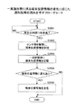
図33は、一実施形態に係る通信端末5f1の端末位置情報の通知処理の一例を示すフローチャートである。端末管理システム7は、所定の時間間隔(例えば1秒間隔)で通信端末5f1に端末位置情報取得要求を送信する。また、通信端末5f1は、予め定められたタイミングで、センサ部1603を駆動し、他の通信端末に対する位置を含む端末位置情報を検知し、検知した位置情報を一次記憶部1602に記憶しているものとする。   FIG. 33 is a flowchart illustrating an example of notification processing of terminal location information of the communication terminal 5f1 according to an embodiment. The terminal management system 7 transmits a terminal location information acquisition request to the communication terminal 5f1 at a predetermined time interval (for example, every 1 second). In addition, the communication terminal 5f1 drives the sensor unit 1603 at a predetermined timing, detects terminal position information including a position with respect to another communication terminal, and stores the detected position information in the primary storage unit 1602. Shall.

図33において、通信端末5f1の制御部1601は、端末位置情報取得要求を受信したか否かを判断し(ステップS3301)、端末位置情報取得要求を受信すると、一次記憶部1602に記憶された端末位置情報を読出す(ステップS3302)。さらに、制御部1601は、読み出した端末位置情報を、送信手段1102を介して、端末管理システム7へ送信する(ステップS3303)。   33, the control unit 1601 of the communication terminal 5f1 determines whether or not a terminal location information acquisition request has been received (step S3301). When the terminal location information acquisition request is received, the terminal stored in the primary storage unit 1602 The position information is read (step S3302). Further, the control unit 1601 transmits the read terminal location information to the terminal management system 7 via the transmission unit 1102 (step S3303).

通信端末5f1は、図33の処理を繰り返すことにより、端末管理システム7からの端末位置情報取得要求に応じて端末位置情報を送信する。   The communication terminal 5f1 transmits the terminal position information in response to the terminal position information acquisition request from the terminal management system 7 by repeating the process of FIG.

また、図34は、一実施形態に係る通信端末5f1の端末位置情報の通知処理の別の一例を示す図である。図34において、通信端末5f1の制御部1601は、所定の時間T1(例えば1秒)を経過すると(ステップS3401)、一次記憶部1602に記憶された端末位置情報を読出す(ステップS3402)。さらに、制御部1601は、読み出した端末位置情報を、送信手段1102を介して、端末管理システム7へ送信する(ステップS3403)。   FIG. 34 is a diagram illustrating another example of the terminal position information notification process of the communication terminal 5f1 according to the embodiment. 34, when a predetermined time T1 (for example, 1 second) elapses (step S3401), the control unit 1601 of the communication terminal 5f1 reads the terminal location information stored in the primary storage unit 1602 (step S3402). Furthermore, the control unit 1601 transmits the read terminal location information to the terminal management system 7 via the transmission unit 1102 (step S3403).

通信端末5f1は、図34の処理を繰り返すことにより、所定時間毎に端末位置情報を端末管理システム7に送信する。   The communication terminal 5f1 transmits the terminal location information to the terminal management system 7 every predetermined time by repeating the process of FIG.

尚、上記図33、34に示した端末位置情報の検出処理は一例であって、例えば、通信端末5f1は、端末位置情報の変化に応じて、端末管理システム7に端末位置情報を送信するものであっても良い。   Note that the terminal position information detection process shown in FIGS. 33 and 34 is an example. For example, the communication terminal 5f1 transmits terminal position information to the terminal management system 7 in accordance with a change in the terminal position information. It may be.

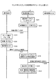
図35は、一実施形態に係る端末位置情報の変化に応じた通知処理の流れを示すフローチャートである。通信端末5f1の制御部1601は、図35に示すように、所定の時間T2(例えば500ms)を経過すると(ステップS3501)、センサ部1603を駆動し端末位置情報を検知する(ステップS3502)。また、通信端末5f1の制御部1601は、検知した端末位置情報を一次記憶部1602に記憶する(ステップS3503)。そして、制御部1601は、一次記憶部1602に記憶されている前回の端末位置情報の検知結果と、ステップS3502で検知した今回の端末位置情報の検知結果を比較し、端末位置情報が変化したか否かを判断する(ステップS3504)。   FIG. 35 is a flowchart illustrating a flow of notification processing according to a change in terminal location information according to an embodiment. As shown in FIG. 35, the control unit 1601 of the communication terminal 5f1 drives the sensor unit 1603 to detect terminal position information when a predetermined time T2 (for example, 500 ms) has elapsed (step S3501) (step S3502). Further, the control unit 1601 of the communication terminal 5f1 stores the detected terminal position information in the primary storage unit 1602 (step S3503). Then, the control unit 1601 compares the previous detection result of the terminal location information stored in the primary storage unit 1602 with the detection result of the current terminal location information detected in step S3502, and whether the terminal location information has changed. It is determined whether or not (step S3504).

ステップS3504において、端末位置情報に変化がある場合、制御部1601は、ステップS3502で検知した今回の端末位置情報を端末管理システム7に送信する。一方、ステップS3504において、端末位置情報に変化が無い場合は、制御部1601は、端末位置情報の送信を行わなくても良い。   If there is a change in the terminal location information in step S3504, the control unit 1601 transmits the current terminal location information detected in step S3502 to the terminal management system 7. On the other hand, if there is no change in the terminal location information in step S3504, the control unit 1601 may not transmit the terminal location information.

通信端末5f1は、上記処理を繰り返すことにより、端末位置情報が変化を検知したとき、すなわち、通信端末5f1と他の通信端末との位置関係が変化したときに、端末位置情報を端末管理システム7に送信することができる。また、図35の処理は、図33又は図34の処理等と組み合わせて実施しても良い。   The communication terminal 5f1 repeats the above processing to detect the terminal position information when the terminal position information detects a change, that is, when the positional relationship between the communication terminal 5f1 and another communication terminal changes. Can be sent to. Also, the process of FIG. 35 may be implemented in combination with the process of FIG. 33 or FIG.

端末管理システム7は、例えば、図33〜35の処理等により、通信端末5f1から端末位置情報を受信すると、図23の端末配置管理テーブル2300のデータラベル2302、ID2303、距離2304の情報を更新する。また、端末管理システム7は、更新されたデータラベル2302、ID2303、距離2304等の情報に基づいて、複数の通信端末の位置関係を特定し、配置位置2305の情報を更新する。さらに、端末管理システム7は、端末配置管理テーブル2300の配置位置2305の情報に基づいて、図21に示した端末管理テーブルの「配置位置」の情報を更新する。   For example, when the terminal management system 7 receives the terminal location information from the communication terminal 5f1 by the processes of FIGS. 33 to 35, the terminal management system 7 updates the information of the data label 2302, ID 2303, and distance 2304 of the terminal arrangement management table 2300 of FIG. . Further, the terminal management system 7 identifies the positional relationship of the plurality of communication terminals based on the updated data label 2302, ID 2303, distance 2304, and the like, and updates the information on the arrangement position 2305. Further, the terminal management system 7 updates the “arrangement position” information of the terminal management table shown in FIG. 21 based on the information of the arrangement position 2305 of the terminal arrangement management table 2300.

<マルチディスプレイの処理>
続いて、マルチディスプレイの処理について説明する。なお、図36乃至図38は、図5に示されているマルチディスプレイの処理を示したシーケンス図である。
<Multi-display processing>
Next, multi-display processing will be described. 36 to 38 are sequence diagrams showing the multi-display process shown in FIG.

ここでは、通信端末5aで再生されている映像(音)〔XYZ〕を、各通信端末(5f1,5f2,5f3)にも分割して再生させる例である。   In this example, the video (sound) [XYZ] reproduced on the communication terminal 5a is also divided and reproduced on each communication terminal (5f1, 5f2, 5f3).

また、ここでは、ウェブコンテンツを表示させるためのブラウザ20を「ブラウザ20a」と示し、ユーザへの設定画面を表示させるためのブラウザ20を「ブラウザ20b」と示す。   Further, here, the browser 20 for displaying web content is indicated as “browser 20a”, and the browser 20 for displaying a setting screen for the user is indicated as “browser 20b”.

まず、配信制御システム2のブラウザ20aは、ウェブサーバ8から取得したウェブコンテンツデータ〔XYZ〕をレンダリングすることにより、静止画(音)データとしての各フレームデータを生成し、送信用FIFO24に出力する(ステップS201)。そして、変換部10が、送信用FIFO24に格納された各フレームデータをエンコードすることで、通信端末5aに配信可能なデータ形式の映像(音)データ〔XYZ〕に変換する(ステップS202)。   First, the browser 20a of the distribution control system 2 generates each frame data as still image (sound) data by rendering the web content data [XYZ] acquired from the web server 8, and outputs the frame data to the transmission FIFO 24. (Step S201). Then, the converter 10 encodes each frame data stored in the transmission FIFO 24 to convert it into video (sound) data [XYZ] in a data format that can be distributed to the communication terminal 5a (step S202).

次に、送受信部31は、通信端末5aの送受信部51に、上記変換部10によって変換された後の映像(音)データ〔XYZ〕を送信する(ステップS203)。これにより、通信端末5aの送受信部51は、映像(音)データ〔XYZ〕を受信して、再生制御部53に出力する。   Next, the transmission / reception unit 31 transmits the video (sound) data [XYZ] converted by the conversion unit 10 to the transmission / reception unit 51 of the communication terminal 5a (step S203). Thereby, the transmission / reception unit 51 of the communication terminal 5 a receives the video (sound) data [XYZ] and outputs it to the reproduction control unit 53.

次に、通信端末5aでは、デコード部50が再生制御部53から映像(音)データ〔XYZ〕を取得してデコードする(ステップS204)。その後、スピーカ61は、デコードされた音データ〔XYZ〕に基づいて音を再生すると共に、表示部58は、レンダリング部55によってデコード部50から取得されてレンダリングされた映像データ〔XYZ〕に基づいて映像を再生する(ステップS205)。   Next, in the communication terminal 5a, the decoding unit 50 acquires the video (sound) data [XYZ] from the reproduction control unit 53 and decodes it (step S204). Thereafter, the speaker 61 reproduces a sound based on the decoded sound data [XYZ], and the display unit 58 is based on the video data [XYZ] obtained and rendered by the rendering unit 55 from the decoding unit 50. The video is reproduced (step S205).

次に、通信端末5aのユーザによって、表示部58上に表示されている画面が不図示のメニュー要求画面に切り替えられ、操作部52が、メニュー要求画面中の不図示の「配信先選択メニュー」ボタンの押下を受け付ける(ステップS206)。これにより、送受信部51が、端末管理システム7の送受信部71aに、配信先選択メニューへの切り替え要求を送信する(ステップS207)。これにより、端末管理システム7の送受信部71aは、配信先選択メニューへの切り替え要求を受信する。この要求には、通信端末5aの端末IDが含まれている。   Next, the user of the communication terminal 5a switches the screen displayed on the display unit 58 to a menu request screen (not shown), and the operation unit 52 displays a “delivery destination selection menu” (not shown) in the menu request screen. A button press is accepted (step S206). Thereby, the transmission / reception part 51 transmits the switch request | requirement to a delivery destination selection menu to the transmission / reception part 71a of the terminal management system 7 (step S207). Thereby, the transmission / reception unit 71a of the terminal management system 7 receives the request for switching to the distribution destination selection menu. This request includes the terminal ID of the communication terminal 5a.

次に、送受信部71bは、配信制御システム2の送受信部21に、ブラウザ20bの起動要求を送信する(ステップS208)。これにより、配信制御システム2の送受信部21は、ブラウザ20bの起動要求を受信し、ブラウザ管理部22に対して、ブラウザ20bの起動要求を行う。   Next, the transmission / reception unit 71b transmits an activation request for the browser 20b to the transmission / reception unit 21 of the distribution control system 2 (step S208). As a result, the transmission / reception unit 21 of the distribution control system 2 receives the activation request for the browser 20b and makes an activation request for the browser 20b to the browser management unit 22.

次に、ブラウザ管理部22は、ブラウザ20bを起動させる(ステップS209)。そして、エンコーダブリッジ部30の作成・選択部310は、ブラウザ20aから変換部10(例えば、変換部10a)への出力を、ブラウザ20bから変換部10(例えば、変換部10b)への出力に切り替える(ステップS210)。但し、通信端末5aが他の通信端末5(例えば、通信端末5b)と変換部10(例えば、変換部10a)を共有して上記ステップS203による映像(音)データを受信していた場合には、他の通信端末5(例えば、通信端末5b)はブラウザ20a用に変換部10(例えば、変換部10a)を利用中であるため、エンコーダブリッジ部30の作成・選択部310は、新たに変換部10(例えば、変換部10b)を作成する。   Next, the browser management unit 22 activates the browser 20b (step S209). Then, the creation / selection unit 310 of the encoder bridge unit 30 switches the output from the browser 20a to the conversion unit 10 (for example, the conversion unit 10a) to the output from the browser 20b to the conversion unit 10 (for example, the conversion unit 10b). (Step S210). However, when the communication terminal 5a shares the conversion unit 10 (for example, the conversion unit 10a) with another communication terminal 5 (for example, the communication terminal 5b) and receives the video (sound) data in the above step S203. Since the other communication terminal 5 (for example, the communication terminal 5b) is using the conversion unit 10 (for example, the conversion unit 10a) for the browser 20a, the creation / selection unit 310 of the encoder bridge unit 30 performs a new conversion. The unit 10 (for example, the conversion unit 10b) is created.

そして、送受信部21は、ブラウザ20bの命令に従って、端末管理システム7の送受信部71bに、配信先選択メニュー要求を送信する(ステップS211)。この際に、通信端末5aの端末IDも送信される。これにより、端末管理システム7の送受信部71bは、配信先選択メニュー要求を受信し、記憶部7000に通信端末5aの端末IDを出力する。   And the transmission / reception part 21 transmits a delivery destination selection menu request | requirement to the transmission / reception part 71b of the terminal management system 7 according to the instruction | indication of the browser 20b (step S211). At this time, the terminal ID of the communication terminal 5a is also transmitted. Thereby, the transmission / reception unit 71b of the terminal management system 7 receives the distribution destination selection menu request and outputs the terminal ID of the communication terminal 5a to the storage unit 7000.

これに対して、端末管理システム7の記憶部7000は、この端末IDに基づいて利用可能端末管理テーブル7020を検索することにより、対応する共有IDを抽出する(ステップS212)。この共有IDは、通信端末5aが遠隔共通処理をするために利用可能な通信端末5を示している。ここでは、図21に示されているように、通信端末5aの端末IDが「t001」であるため、抽出される共有IDは「v003」、「v006」である。   In response to this, the storage unit 7000 of the terminal management system 7 searches the available terminal management table 7020 based on this terminal ID to extract the corresponding shared ID (step S212). This shared ID indicates the communication terminal 5 that can be used by the communication terminal 5a for remote common processing. Here, as shown in FIG. 21, since the terminal ID of the communication terminal 5a is “t001”, the extracted shared IDs are “v003” and “v006”.

更に、記憶部7000は、抽出した共有IDに基づいて端末管理テーブル7010を検索することにより、対応する表示名を示す表示名情報を抽出する(ステップS213)。ここでは、図20に示されているように、抽出された共有ID「v003」、「v006」に対応する表示名は、それぞれ「東京本社10F MFP」、「大阪展示場1F マルチディスプレイ」である。   Further, the storage unit 7000 searches the terminal management table 7010 based on the extracted shared ID, thereby extracting display name information indicating the corresponding display name (step S213). Here, as shown in FIG. 20, the display names corresponding to the extracted shared IDs “v003” and “v006” are “Tokyo head office 10F MFP” and “Osaka exhibition hall 1F multi-display”, respectively. .

そして、送受信部71bは、配信制御システム2の送受信部21に、コンテンツデータとしての配信先選択メニューデータ〔M〕を送信する(ステップS214)。これにより、配信制御システム2の送受信部21は、配信先選択メニューデータ〔M〕を受信し、ブラウザ20bに出力する。この配信先選択メニュー〔M〕は、図20に示されているように、チェックボックス、共有ID、及び表示名が含まれている。   Then, the transmission / reception unit 71b transmits distribution destination selection menu data [M] as content data to the transmission / reception unit 21 of the distribution control system 2 (step S214). Thereby, the transmission / reception unit 21 of the distribution control system 2 receives the distribution destination selection menu data [M] and outputs it to the browser 20b. As shown in FIG. 20, the distribution destination selection menu [M] includes a check box, a shared ID, and a display name.

次に、図37に示されているように、ブラウザ20bが、端末管理システム7から取得した配信先選択メニュー〔M〕を示すコンテンツデータをレンダリングして画像(音)データを生成し、送信用FIFO24に出力する(ステップS221)。そして、変換部10が、送信用FIFO24に格納された画像(音)データ〔M〕をエンコードすることで、通信端末5aに配信すべき映像(音)データ〔M〕に変換する(ステップS222)。   Next, as shown in FIG. 37, the browser 20b renders the content data indicating the distribution destination selection menu [M] acquired from the terminal management system 7 to generate image (sound) data, and transmits it. The data is output to the FIFO 24 (step S221). Then, the conversion unit 10 encodes the image (sound) data [M] stored in the transmission FIFO 24 to convert it into video (sound) data [M] to be distributed to the communication terminal 5a (step S222). .

次に、送受信部31は、通信端末5aの送受信部51に、上記変換部10によって変換された後の映像(音)データ〔M〕を送信する(ステップS223)。これにより、通信端末5aの送受信部51は、映像(音)データ〔M〕を受信して、再生制御部53に出力する。   Next, the transmission / reception unit 31 transmits the video (sound) data [M] after being converted by the conversion unit 10 to the transmission / reception unit 51 of the communication terminal 5a (step S223). Thereby, the transmission / reception unit 51 of the communication terminal 5 a receives the video (sound) data [M] and outputs it to the reproduction control unit 53.

次に、通信端末5aでは、デコード部50が再生制御部53から映像(音)データ〔M〕を取得してデコードする(ステップS224)。その後、表示部58は、レンダリング部55によってデコード部50から取得されてレンダリングされた映像データ〔XYZ〕に基づいて、図20に示されているような映像を再生する(ステップS225)。   Next, in the communication terminal 5a, the decoding unit 50 acquires the video (sound) data [M] from the reproduction control unit 53 and decodes it (step S224). After that, the display unit 58 reproduces the video as shown in FIG. 20 based on the video data [XYZ] obtained and rendered by the rendering unit 55 from the decoding unit 50 (step S225).

次に、図20に示されている配信先選択メニューにおいて、ユーザにより共有ID「v006」のチェックボックスにチェックが入れられ、「OK」ボタンが押下されると、操作部52が、ユーザの操作入力を受け付ける(ステップS226)。   Next, in the distribution destination selection menu shown in FIG. 20, when the user checks the check box of the shared ID “v006” and presses the “OK” button, the operation unit 52 causes the user operation to be performed. An input is accepted (step S226).

次に、送受信部51は、配信制御システム2の送受信部31に、操作データとしてチェック結果を送信する(ステップS227)。これにより、配信制御システム2の送受信部31は、操作データとしてチェック結果を受信し、ブラウザ20bに出力する。   Next, the transmission / reception unit 51 transmits the check result as operation data to the transmission / reception unit 31 of the distribution control system 2 (step S227). Thereby, the transmission / reception unit 31 of the distribution control system 2 receives the check result as operation data and outputs it to the browser 20b.

次に、ブラウザ20bは、チェック結果から共有IDを選択する(ステップS228)。   Next, the browser 20b selects a shared ID from the check result (step S228).

そして、送受信部21は、ブラウザ20bの命令に従って、端末管理システム7の送受信部71bに、配信先追加要求を送信する(ステップS229)。この配信先追加要求には、上記ステップS227によって選択された共有IDが含まれている。これにより、端末管理システム7の送受信部71bは、配信先追加要求を受信し、記憶部7000に共有IDを出力する。そして、ブラウザ20bは、役目を終えて終了する(ステップS230)。これにより、エンコーダブリッジ部30の作成・選択部310は、ブラウザ20bから変換部10への出力を、ブラウザ20aから変換部10への出力に戻すよう切り替える(ステップS231)。   Then, the transmission / reception unit 21 transmits a distribution destination addition request to the transmission / reception unit 71b of the terminal management system 7 according to the instruction of the browser 20b (step S229). This distribution destination addition request includes the shared ID selected in step S227. Thereby, the transmission / reception unit 71b of the terminal management system 7 receives the distribution destination addition request and outputs the shared ID to the storage unit 7000. Then, the browser 20b finishes its role and ends (step S230). Thereby, the creation / selection unit 310 of the encoder bridge unit 30 switches the output from the browser 20b to the conversion unit 10 so as to return to the output from the browser 20a to the conversion unit 10 (step S231).

次に、図38に示されているように、端末管理システム7の記憶部7000では、上記ステップS229によって送られて来た共有IDに基づいて、端末管理テーブル7010を検索することにより、対応する端末ID及び設置位置情報を抽出する(ステップS241)。そして、送受信部71bは、配信制御システム2の送受信部21に、配信先の追加指示を送信する(ステップS242)。この配信先の追加指示には、上記ステップS241によって抽出された端末ID及び設置位置情報が含まれている。これにより、配信制御システム2の送受信部21は、配信先の追加指示を受信し、ブラウザ管理部22に配信先の追加指示を出力する。ここでは、端末ID及び設置位置情報が「t006」、「左」と、端末ID及び設置位置情報が「t007」、「中」と、端末ID及び設置位置情報が「t008」、「右」との3組の端末ID及び設置位置情報が含まれている。   Next, as shown in FIG. 38, the storage unit 7000 of the terminal management system 7 responds by searching the terminal management table 7010 based on the shared ID sent in step S229. Terminal ID and installation position information are extracted (step S241). Then, the transmission / reception unit 71b transmits a distribution destination addition instruction to the transmission / reception unit 21 of the distribution control system 2 (step S242). This distribution destination addition instruction includes the terminal ID and installation position information extracted in step S241. As a result, the transmission / reception unit 21 of the distribution control system 2 receives the distribution destination addition instruction and outputs the distribution destination addition instruction to the browser management unit 22. Here, the terminal ID and installation position information are “t006” and “left”, the terminal ID and installation position information are “t007” and “middle”, and the terminal ID and installation position information are “t008” and “right”. The three sets of terminal IDs and installation position information are included.

次に、エンコーダブリッジ部30の作成・選択部310は、マルチディスプレイ用の変換部10を作成する(ステップS243)。なお、この場合、エンコーダブリッジ部30の作成・選択部310は、ブラウザ管理部22から、端末ID及び設置位置情報を取得する。   Next, the creation / selection unit 310 of the encoder bridge unit 30 creates the conversion unit 10 for multi-display (step S243). In this case, the creation / selection unit 310 of the encoder bridge unit 30 acquires the terminal ID and the installation position information from the browser management unit 22.

そして、上記ステップS243によって作成された変換部10の分割部13が、送信用FIFO24に格納されている静止画(音)データとしての各フレームデータ〔XYZ〕を分割し、エンコード部19が、分割された各フレームデータをエンコードする(ステップS244)。   Then, the dividing unit 13 of the converting unit 10 created in step S243 divides each frame data [XYZ] as still image (sound) data stored in the transmission FIFO 24, and the encoding unit 19 Each frame data thus encoded is encoded (step S244).

そして、送受信部31は、エンコーダブリッジ部30によってエンコードされた映像(音)データ〔X〕を、端末ID(「t006」)及び設置位置情報(「左」)に基づいて、通信端末5f1の送受信部51に送信する(ステップS245−1)。これにより、通信端末5f1の送受信部51は、映像(音)データ〔X〕を受信して、再生制御部53に出力する。   Then, the transmission / reception unit 31 transmits / receives the video (sound) data [X] encoded by the encoder bridge unit 30 based on the terminal ID (“t006”) and the installation position information (“left”). It transmits to the part 51 (step S245-1). Thereby, the transmission / reception unit 51 of the communication terminal 5f1 receives the video (sound) data [X] and outputs it to the reproduction control unit 53.

次に、通信端末5f1では、デコード部50が再生制御部53から映像(音)データ〔X〕を取得してデコードする(ステップS246−1)。その後、スピーカ61は、デコードされた音データ〔X〕に基づいて音を再生すると共に、表示部58は、レンダリング部55によってデコード部50から取得されてレンダリングされた映像データ〔X〕に基づいて映像を再生する(ステップS247−1)。   Next, in the communication terminal 5f1, the decoding unit 50 acquires the video (sound) data [X] from the reproduction control unit 53 and decodes it (step S246-1). Thereafter, the speaker 61 reproduces a sound based on the decoded sound data [X], and the display unit 58 is based on the video data [X] obtained by the rendering unit 55 from the decoding unit 50 and rendered. The video is reproduced (step S247-1).

また、同様にして、送受信部31は、エンコーダブリッジ部30によってエンコードされた映像(音)データ〔Y〕を、端末ID(「t007」)及び設置位置情報(「中」)に基づいて、通信端末5f2の送受信部51に送信する(ステップS245−2)。これにより、通信端末5f2の送受信部51は、映像(音)データ〔Y〕を受信して、再生制御部53に出力する。   Similarly, the transmission / reception unit 31 communicates the video (sound) data [Y] encoded by the encoder bridge unit 30 based on the terminal ID (“t007”) and the installation position information (“middle”). It transmits to the transmission / reception part 51 of the terminal 5f2 (step S245-2). Thereby, the transmission / reception unit 51 of the communication terminal 5 f 2 receives the video (sound) data [Y] and outputs it to the reproduction control unit 53.

次に、通信端末5f2では、デコード部50が再生制御部53から映像(音)データ〔Y〕を取得してデコードする(ステップS246−2)。その後、スピーカ61は、デコードされた音データ〔Y〕に基づいて音を再生すると共に、表示部58は、レンダリング部55によってデコード部50から取得されてレンダリングされた映像データ〔Y〕に基づいて映像を再生する(ステップS247−2)。   Next, in the communication terminal 5f2, the decoding unit 50 acquires the video (sound) data [Y] from the reproduction control unit 53 and decodes it (step S246-2). Thereafter, the speaker 61 reproduces sound based on the decoded sound data [Y], and the display unit 58 is based on the video data [Y] acquired and rendered from the decoding unit 50 by the rendering unit 55. The video is reproduced (step S247-2).

更に、同様にして、送受信部31は、エンコーダブリッジ部30によってエンコードされた映像(音)データ「Z」を、端末ID(「t008」)及び設置位置情報(「右」)に基づいて、通信端末5f3の送受信部51に送信する(ステップS235−3)。これにより、通信端末5f3の送受信部51は、映像(音)データ〔Z〕を受信して、再生制御部53に出力する。
次に、通信端末5f3では、デコード部50が再生制御部53から映像(音)データ〔Z〕を取得してデコードする(ステップS246−3)。その後、スピーカ61は、デコードされた音データ〔Z〕に基づいて音を再生すると共に、表示部58は、レンダリング部55によってデコード部50から取得されてレンダリングされた映像データ〔Z〕に基づいて映像を再生する(ステップS247−3)。
Further, similarly, the transmission / reception unit 31 communicates the video (sound) data “Z” encoded by the encoder bridge unit 30 based on the terminal ID (“t008”) and the installation position information (“right”). It transmits to the transmission / reception part 51 of the terminal 5f3 (step S235-3). As a result, the transmission / reception unit 51 of the communication terminal 5f3 receives the video (sound) data [Z] and outputs it to the reproduction control unit 53.
Next, in the communication terminal 5f3, the decoding unit 50 acquires the video (sound) data [Z] from the reproduction control unit 53 and decodes it (step S246-3). Thereafter, the speaker 61 reproduces sound based on the decoded sound data [Z], and the display unit 58 is based on the video data [Z] obtained and rendered by the rendering unit 55 from the decoding unit 50. The video is reproduced (step S247-3).

[実施形態の主な効果]
以上、本実施の形態によれば、ユーザが複数の表示装置(通信端末)を並べて配置して、複数の表示装置で所定の画像を表示することを容易化することができる。このとき、本実施の形態に係る表示装置は、自律的に他の表示装置との位置関係を検知するので、予め表示装置の配置等をシステムに登録する、又は、ユーザが手動で設定を行う等の面倒な操作によらずに所定の画像を表示することができる。
[Main effects of the embodiment]
As described above, according to the present embodiment, a user can easily arrange a plurality of display devices (communication terminals) side by side and display a predetermined image on the plurality of display devices. At this time, since the display device according to the present embodiment autonomously detects the positional relationship with other display devices, the arrangement of the display device or the like is registered in the system in advance, or the user manually sets the display device. A predetermined image can be displayed without troublesome operations such as the above.

さらに、複数の表示装置で画像を表示中に、表示装置の配置を変えた場合、又は表示装置の数を変えた場合等でも、表示コンテンツを正しく表示することができる。また、他の表示装置の識別情報(端末ID)と距離を利用することにより、コンテンツの多様な表示状態を制御することができ、ユーザビリティが向上する。   Furthermore, display content can be correctly displayed even when the arrangement of display devices is changed or the number of display devices is changed while images are displayed on a plurality of display devices. In addition, by using the identification information (terminal ID) and distance of other display devices, various display states of content can be controlled, and usability is improved.

[補足説明]
上記実施の形態は本発明に係る表示装置及び表示システムの一例であって、目的や用途に応じて様々な応用が可能であることは言うまでもない。
[Supplemental explanation]
The above embodiment is an example of the display device and the display system according to the present invention, and it goes without saying that various applications are possible according to the purpose and application.

例えば、上記実施の形態では、図5に示したマルチディスプレイの場合について説明を行ったが、図4のマルチキャストの場合への応用も可能である。例えば、図4において、通信端末5f1、5f2、5f3には、それぞれ同一の画像「A」が配信されている。この状態で、通信端末5f1の右側に5f2を近接配置させると、通信端末5f1の検知手段1101は、通信端末5f1の右側に通信端末5f2が配置されたことを検知する。   For example, in the above embodiment, the case of the multi-display shown in FIG. 5 has been described, but application to the multicast case of FIG. 4 is also possible. For example, in FIG. 4, the same image “A” is distributed to each of the communication terminals 5f1, 5f2, and 5f3. In this state, when 5f2 is placed close to the right side of the communication terminal 5f1, the detection unit 1101 of the communication terminal 5f1 detects that the communication terminal 5f2 is placed on the right side of the communication terminal 5f1.

このとき、通信端末5f1の表示手段1103は、例えば、配信されている画像「A」の左半分を表示するように制御を行う。また、同様にして、通信端末5f2は、左側に通信端末5f1が配置されたことを検知すると、配信されている画像「A」の右半分を表示する。例えば、このような方法によっても、上記実施の形態と同様の効果を奏することができる。尚、この場合、上記画像「A」は、必ずしもサーバから配信された画像でなくても良い。例えば、外部記録媒体等から取得した共通の画像等であっても良い。   At this time, the display unit 1103 of the communication terminal 5f1 performs control to display the left half of the distributed image “A”, for example. Similarly, when the communication terminal 5f2 detects that the communication terminal 5f1 is arranged on the left side, the communication terminal 5f2 displays the right half of the distributed image “A”. For example, even by such a method, the same effect as that of the above embodiment can be obtained. In this case, the image “A” is not necessarily an image distributed from the server. For example, a common image acquired from an external recording medium or the like may be used.

さらに、本実施形態の配信システム1では、端末管理システム7と配信制御システム2とを互いに別個の装置として構成しているが、例えば、配信制御システム2に端末管理システム7の機能を持たせるなどにより、端末管理システム7と配信制御システム2とを一体の装置として構成するようにしてもよい。   Furthermore, in the distribution system 1 of the present embodiment, the terminal management system 7 and the distribution control system 2 are configured as separate devices. For example, the distribution control system 2 has the function of the terminal management system 7. Thus, the terminal management system 7 and the distribution control system 2 may be configured as an integrated device.

また、上記実施形態における配信制御システム2、及び端末管理システム7は、単一のコンピュータによって構築されてもよいし、各部(機能、手段、又は記憶部)を分割して任意に割り当てられた複数のコンピュータによって構築されていてもよい。   Further, the distribution control system 2 and the terminal management system 7 in the above embodiment may be constructed by a single computer, or a plurality of units arbitrarily assigned by dividing each unit (function, means, or storage unit). It may be constructed by a computer.

更に、上記実施形態の各プログラムが記憶されたCD−ROM等の記録媒体、並びに、これらプログラムが記憶されたHDD204は、いずれもプログラム製品(Program Product)として、国内又は国外へ提供されることができる。   Further, a recording medium such as a CD-ROM in which the programs of the above-described embodiments are stored, and the HDD 204 in which these programs are stored can be provided domestically or abroad as a program product. it can.

1100 表示システム
1101 検知手段
1102 送信手段
1103 表示手段
1104 受信手段
1106 表示制御手段
1108 位置情報管理手段
1603、1603A〜1603D センサ部
2401、2404 カメラ(撮像手段)
2402、2403 バーコード(識別コード)
2501、2504 ICカードリーダ(ICタグリーダ)
2502、2503 ICカード(ICタグ)
2701、2704 赤外線受信素子(受光素子)
2702、2703 赤外線送信素子(発光素子)
2805A、2805B 送受信面
3001A〜3001H 遮光板
3101A〜3101D 集光レンズ
5f1、5f2、5f3 通信端末(表示装置)
DESCRIPTION OF SYMBOLS 1100 Display system 1101 Detection means 1102 Transmission means 1103 Display means 1104 Reception means 1106 Display control means 1108 Position information management means 1603, 1603A-1603D Sensor part 2401, 2404 Camera (imaging means)
2402, 2403 Barcode (identification code)
2501, 2504 IC card reader (IC tag reader)
2502, 2503 IC card (IC tag)
2701, 2704 Infrared light receiving element (light receiving element)
2702, 2703 Infrared transmitting element (light emitting element)
2805A, 2805B Transmission / reception surfaces 3001A to 3001H Light shielding plates 3101A to 3101D Condensing lenses 5f1, 5f2, 5f3 Communication terminals (display devices)

特許第51522881号公報Japanese Patent No. 51522881

Claims (9)

所定の画像を表示する表示装置であって、
当該表示装置に対する他の表示装置の位置を識別する情報、及び前記他の表示装置の識別情報を含む端末位置情報を検知する検知部と、
前記検知した端末位置情報に基づいて前記所定の画像の一部を表示する表示部と、
を有し、
前記検知部は、当該表示装置の左、右、上、下の各辺に対応して設けられ、隣接する送信素子及び受信素子を備えたセンサ部を有し、
前記センサ部の各々は
該表示装置の各辺に対応して設けられ、当該表示装置の識別情報を送信する発光素子と、前記発光素子に隣接して配置され、前記他の表示装置のうちの一の表示装置の識別情報を受信する受光素子、
を有し、
当該表示装置の左辺に対応して設けられた前記センサ部の前記送信素子及び前記受信素子は、それぞれ、当該センサ部の上側及び下側に配置され、
当該表示装置の右辺に対応して設けられた前記センサ部の前記送信素子及び前記受信素子は、それぞれ、当該センサ部の下側及び上側に配置され、
当該表示装置の下辺に対応して設けられた前記センサ部の前記送信素子及び前記受信素子は、それぞれ、当該センサ部の右側及び左側に配置され、
当該表示装置の上辺に対応して設けられた前記センサ部の前記送信素子及び前記受信素子は、それぞれ、当該センサ部の左側及び右側に配置され
前記センサ部の送受信面は、当該表示装置を設置した床面の法線、又は前記センサ部が設けられた辺に対して所定の角度の傾きを有する
表示装置。
A display device for displaying a predetermined image,
A detection unit for detecting terminal position information including information for identifying a position of another display device relative to the display device, and identification information for the other display device;
A display unit for displaying a part of the predetermined image based on the detected terminal position information;
Have
The detection unit is provided corresponding to each of the left, right, upper, and lower sides of the display device, and has a sensor unit including an adjacent transmission element and reception element,
Each of the sensor units is
Provided corresponding to respective sides of those said display device, a light emitting element for transmitting the identification information of the display device, disposed adjacent to the light emitting element, one of the display device of said other display devices A light receiving element for receiving identification information;
Have
The transmitting element and the receiving element of the sensor unit provided corresponding to the left side of the display device are respectively disposed on the upper side and the lower side of the sensor unit,
The transmitting element and the receiving element of the sensor unit provided corresponding to the right side of the display device are respectively disposed on the lower side and the upper side of the sensor unit,
The transmitting element and the receiving element of the sensor unit provided corresponding to the lower side of the display device are respectively disposed on the right side and the left side of the sensor unit,
The transmitting element and the receiving element of the sensor unit provided corresponding to the upper side of the display device are respectively disposed on the left side and the right side of the sensor unit ,
The transmission / reception surface of the sensor unit has an inclination of a predetermined angle with respect to the normal of the floor surface on which the display device is installed, or the side on which the sensor unit is provided .
Display device.
当該表示装置は、前記他の表示装置と同じ向きで隣接配置された場合、
当該表示装置のセンサ部の送受信面と、前記他の表示装置のセンサ部の送受信面とが対向する請求項に記載の表示装置。
When the display device is adjacently arranged in the same direction as the other display device,
And receiving surface of the sensor portion of the display device, the display device according to claim 1, wherein the transmission and reception surface of the sensor portion of the other display devices facing.
前記センサ部は、前記発光素子の発光範囲又は前記受光素子の受光範囲を制限する遮光板又は遮光面を有する請求項1又は2に記載の表示装置。 The sensor unit includes a display device according to claim 1 or 2 having a light shielding plate or the light shielding surface to limit the emission range or receiving range of the light receiving element of the light emitting element. 前記発光素子の発光範囲又は前記受光素子の受光範囲を制限する集光レンズを有する請求項乃至のいずれか一項に記載の表示装置。 Display device according to any one of claims 1 to 3 having a condenser lens to restrict the emission range or receiving range of the light receiving element of the light emitting element. 前記検知部は、隣接して配置された前記他の表示装置との距離が所定の範囲内である場合に、前記端末位置情報を検知する請求項1乃至のいずれか一項に記載の表示装置。 The display according to any one of claims 1 to 4 , wherein the detection unit detects the terminal position information when a distance from the other display device arranged adjacently is within a predetermined range. apparatus. 前記他の表示装置と協働して前記所定の画像を表示する請求項1乃至のいずれか一項に記載の表示装置。 The other display devices in cooperation with the display device according to any one of claims 1 to 5 for displaying the predetermined image. 前記検知部によって検知された前記端末位置情報を所定の装置に送信する送信部を有する請求項1に記載の表示装置。   The display device according to claim 1, further comprising: a transmission unit configured to transmit the terminal position information detected by the detection unit to a predetermined device. 前記所定の装置は、前記画像の一部を特定するための情報を決定する請求項に記載の表示装置。 The display device according to claim 7 , wherein the predetermined device determines information for specifying a part of the image. 請求項1乃至のいずれか一項に記載の表示装置を複数有し、複数の前記表示装置を用いて所定の画像を表示する表示システムであって、
複数の前記表示装置の位置関係を検知する第1の装置と、
前記第1の装置によって検知された位置関係に基づいて、前記表示装置のそれぞれに前記所定の画像の一部を表示させる第2の装置と、
を有する表示システム。
It has a plurality of display device according to any one of claims 1 to 8, a display system for displaying a predetermined image by using a plurality of said display device,
A first device for detecting a positional relationship among a plurality of the display devices;
A second device that displays a part of the predetermined image on each of the display devices based on the positional relationship detected by the first device;
Display system.
JP2014088994A 2013-09-05 2014-04-23 Display device and display system Active JP6427937B2 (en)

Priority Applications (4)

Application Number Priority Date Filing Date Title
JP2014088994A JP6427937B2 (en) 2013-09-05 2014-04-23 Display device and display system
EP14182541.4A EP2846254B1 (en) 2013-09-05 2014-08-27 Display apparatus and display system
US14/477,086 US9866611B2 (en) 2013-09-05 2014-09-04 Display apparatus and display system
CN201410848803.2A CN104660675B (en) 2013-09-05 2014-09-05 Display device and display system

Applications Claiming Priority (3)

Application Number Priority Date Filing Date Title
JP2013183717 2013-09-05
JP2014088994A JP6427937B2 (en) 2013-09-05 2014-04-23 Display device and display system

Publications (3)

Publication Number Publication Date
JP2015072446A JP2015072446A (en) 2015-04-16
JP2015072446A5 JP2015072446A5 (en) 2017-06-08
JP6427937B2 true JP6427937B2 (en) 2018-11-28

Family

ID=51483223

Family Applications (1)

Application Number Title Priority Date Filing Date
JP2014088994A Active JP6427937B2 (en) 2013-09-05 2014-04-23 Display device and display system

Country Status (4)

Country Link
US (1) US9866611B2 (en)
EP (1) EP2846254B1 (en)
JP (1) JP6427937B2 (en)
CN (1) CN104660675B (en)

Families Citing this family (11)

* Cited by examiner, † Cited by third party
Publication number Priority date Publication date Assignee Title
JP6459545B2 (en) * 2015-01-21 2019-01-30 株式会社リコー Image processing apparatus, image processing system, and image processing method
JP6451846B2 (en) 2015-06-23 2019-01-16 株式会社リコー COMMUNICATION SYSTEM, COMMUNICATION SYSTEM CONTROL METHOD, AND PROGRAM
US9736531B2 (en) 2015-09-08 2017-08-15 Google Inc. Video media streaming device
US10277275B2 (en) 2015-09-08 2019-04-30 Google Llc Audio media streaming device
KR102383913B1 (en) * 2015-10-16 2022-04-07 삼성전자 주식회사 Method and apparatus for transmitting and receiving information by electronic device
JP2017111589A (en) 2015-12-16 2017-06-22 株式会社リコー Coordinate detection device, display system, projection system and coordinate detection method
KR20180023664A (en) * 2016-08-26 2018-03-07 삼성전자주식회사 A display apparatus, a multi-display system and a method for controlling the same
JP2018036292A (en) * 2016-08-29 2018-03-08 セイコーエプソン株式会社 Display device, controller, display method and program
WO2018142159A1 (en) 2017-02-03 2018-08-09 Tv One Limited Method of video transmission and display
GB2561812A (en) * 2017-02-03 2018-10-31 Tv One Ltd Method of video transmission and display
CN107066074A (en) * 2017-04-12 2017-08-18 广东南方新视界传媒科技有限公司 A kind of many environment-friendly and energy-saving control methods of LED display and system

Family Cites Families (36)

* Cited by examiner, † Cited by third party
Publication number Priority date Publication date Assignee Title
US4713534A (en) 1986-02-18 1987-12-15 Carroll Touch Inc. Phototransistor apparatus with current injection ambient compensation
KR100229603B1 (en) * 1997-04-15 1999-11-15 윤종용 A computer system provided with infrared communication cable
JPH11259235A (en) 1998-03-12 1999-09-24 Ricoh Co Ltd Coordinate inputting device
JP4627781B2 (en) 1998-05-11 2011-02-09 株式会社リコー Coordinate input / detection device and electronic blackboard system
JP2000105671A (en) 1998-05-11 2000-04-11 Ricoh Co Ltd Coordinate input and detecting device, and electronic blackboard system
JP4033582B2 (en) 1998-06-09 2008-01-16 株式会社リコー Coordinate input / detection device and electronic blackboard system
JP2000043484A (en) 1998-07-30 2000-02-15 Ricoh Co Ltd Electronic whiteboard system
JP3393817B2 (en) * 1998-10-16 2003-04-07 株式会社堀場製作所 Particle size distribution measuring device
JP4057200B2 (en) 1999-09-10 2008-03-05 株式会社リコー Coordinate input device and recording medium for coordinate input device
JP3905670B2 (en) 1999-09-10 2007-04-18 株式会社リコー Coordinate input detection apparatus, information storage medium, and coordinate input detection method
JP4059620B2 (en) 2000-09-20 2008-03-12 株式会社リコー Coordinate detection method, coordinate input / detection device, and storage medium
JP4655439B2 (en) * 2001-09-13 2011-03-23 ソニー株式会社 Information processing apparatus and method, and program
JP4261145B2 (en) 2001-09-19 2009-04-30 株式会社リコー Information processing apparatus, information processing apparatus control method, and program for causing computer to execute the method
JP3797915B2 (en) * 2001-10-25 2006-07-19 シチズン電子株式会社 Bi-directional optical transmission device
JP3711973B2 (en) * 2002-10-09 2005-11-02 株式会社日立製作所 Projection display
BRPI0417656A (en) 2003-12-19 2007-04-03 Speechgear Inc method, computer readable medium, and system
JP4677733B2 (en) * 2004-04-15 2011-04-27 ソニー株式会社 Server device, display device, and display method
JP4210240B2 (en) * 2004-06-03 2009-01-14 ローム株式会社 Optical communication module
JP4736363B2 (en) * 2004-07-15 2011-07-27 富士ゼロックス株式会社 Image browsing system
JP4843428B2 (en) 2005-09-16 2011-12-21 株式会社リコー Information processing apparatus, information processing method, and information processing system
JP5672830B2 (en) 2010-08-06 2015-02-18 株式会社リコー Image display control device, image display system, image display method, program, and recording medium
JP2012070360A (en) 2010-08-26 2012-04-05 Ricoh Co Ltd Control device, image forming device, and control method
JP2012084122A (en) 2010-09-15 2012-04-26 Ricoh Co Ltd Image display device, image display system, image display method, program and recording medium
JP2012185798A (en) 2011-02-16 2012-09-27 Ricoh Co Ltd Coordinate detection system, information processor, method, program and recording medium
JP5589909B2 (en) 2011-03-14 2014-09-17 株式会社リコー Display device, display device event switching control method, and program
CN102915218A (en) * 2011-08-01 2013-02-06 富泰华工业(深圳)有限公司 Image displaying method and electronic devices
JP5152881B1 (en) 2011-10-18 2013-02-27 浩一 三島 Image upload system and image browsing system
JP6069898B2 (en) 2011-11-25 2017-02-01 株式会社リコー Image processing apparatus, image processing system, method, and program
JP6106983B2 (en) 2011-11-30 2017-04-05 株式会社リコー Image display device, image display system, method and program
US20130222266A1 (en) * 2012-02-24 2013-08-29 Dan Zacharias GÄRDENFORS Method and apparatus for interconnected devices
JP2013210956A (en) 2012-03-30 2013-10-10 Ricoh Co Ltd Display device
JP6015452B2 (en) 2013-01-07 2016-10-26 株式会社リコー Image processing apparatus, method, and program
JP2014200076A (en) 2013-03-15 2014-10-23 株式会社リコー Distribution control system, distribution control method, and program
JP2014200075A (en) 2013-03-15 2014-10-23 株式会社リコー Computer system, distribution control system, distribution control method, and program
JP2014200074A (en) 2013-03-15 2014-10-23 株式会社リコー Distribution control system, distribution control method, and program
EP2974327A4 (en) 2013-03-15 2016-03-09 Ricoh Co Ltd Distribution control system and distribution system

Also Published As

Publication number Publication date
CN104660675A (en) 2015-05-27
US9866611B2 (en) 2018-01-09
US20150067532A1 (en) 2015-03-05
EP2846254A3 (en) 2015-06-24
JP2015072446A (en) 2015-04-16
EP2846254A2 (en) 2015-03-11
EP2846254B1 (en) 2017-04-12
CN104660675B (en) 2018-04-27

Similar Documents

Publication Publication Date Title
JP6427937B2 (en) Display device and display system
JP6354764B2 (en) Distribution management apparatus, distribution method, and program
CN104052798B (en) Dcs and distributed control method
JP6326855B2 (en) Delivery control system, delivery system, delivery control method, and program
JP6337499B2 (en) Delivery control system, delivery system, delivery control method, and program
JP6398215B2 (en) Delivery control system, delivery system, delivery control method, and program
JP6323048B2 (en) Distribution system, distribution method, and program
JP6354195B2 (en) Distribution system, distribution method, and program
JP2014200074A (en) Distribution control system, distribution control method, and program
JP2015056855A (en) Distribution management device and distribution management system
JP2014200075A (en) Computer system, distribution control system, distribution control method, and program
JP2016143236A (en) Distribution control device, distribution control method, and program
WO2015045787A1 (en) Distribution management device, terminal, and distribution management method
JP6589261B2 (en) Delivery control system, delivery control method, and program
JP2015069244A (en) Distribution system, distribution method, and program
JP2016063247A (en) Distribution system and distribution method
JP2015056046A (en) Distribution management system, distribution system, distribution management method, and program
JP2016004352A (en) Terminal management system, terminal management method, and program
JP6442832B2 (en) Delivery control system, delivery system, delivery control method, and program
JP6387623B2 (en) Distribution control system
JP6375638B2 (en) Delivery control system, delivery system, delivery control method, and program
JP6248492B2 (en) Distribution management device, distribution management system, and distribution management method
JP2016058812A (en) Distribution control system, distribution system, distribution control system control method, and program
JP2015061107A (en) Distribution management device and distribution system
JP2015053613A (en) Video distribution device and video distribution system

Legal Events

Date Code Title Description
A521 Request for written amendment filed

Free format text: JAPANESE INTERMEDIATE CODE: A523

Effective date: 20170424

A621 Written request for application examination

Free format text: JAPANESE INTERMEDIATE CODE: A621

Effective date: 20170424

A977 Report on retrieval

Free format text: JAPANESE INTERMEDIATE CODE: A971007

Effective date: 20180221

A131 Notification of reasons for refusal

Free format text: JAPANESE INTERMEDIATE CODE: A131

Effective date: 20180306

A521 Request for written amendment filed

Free format text: JAPANESE INTERMEDIATE CODE: A523

Effective date: 20180427

TRDD Decision of grant or rejection written
A01 Written decision to grant a patent or to grant a registration (utility model)

Free format text: JAPANESE INTERMEDIATE CODE: A01

Effective date: 20181002

A61 First payment of annual fees (during grant procedure)

Free format text: JAPANESE INTERMEDIATE CODE: A61

Effective date: 20181015

R151 Written notification of patent or utility model registration

Ref document number: 6427937

Country of ref document: JP

Free format text: JAPANESE INTERMEDIATE CODE: R151