JP6422741B2 - Smartphone stand for vehicles - Google Patents
Smartphone stand for vehicles Download PDFInfo
- Publication number
- JP6422741B2 JP6422741B2 JP2014225114A JP2014225114A JP6422741B2 JP 6422741 B2 JP6422741 B2 JP 6422741B2 JP 2014225114 A JP2014225114 A JP 2014225114A JP 2014225114 A JP2014225114 A JP 2014225114A JP 6422741 B2 JP6422741 B2 JP 6422741B2
- Authority
- JP
- Japan
- Prior art keywords
- cradle
- smartphone
- slider
- charging
- vehicle
- Prior art date
- Legal status (The legal status is an assumption and is not a legal conclusion. Google has not performed a legal analysis and makes no representation as to the accuracy of the status listed.)
- Active
Links
Images


Classifications
-
- B—PERFORMING OPERATIONS; TRANSPORTING
- B60—VEHICLES IN GENERAL
- B60R—VEHICLES, VEHICLE FITTINGS, OR VEHICLE PARTS, NOT OTHERWISE PROVIDED FOR
- B60R11/00—Arrangements for holding or mounting articles, not otherwise provided for
- B60R11/02—Arrangements for holding or mounting articles, not otherwise provided for for radio sets, television sets, telephones, or the like; Arrangement of controls thereof
-
- H—ELECTRICITY
- H04—ELECTRIC COMMUNICATION TECHNIQUE
- H04B—TRANSMISSION
- H04B1/00—Details of transmission systems, not covered by a single one of groups H04B3/00 - H04B13/00; Details of transmission systems not characterised by the medium used for transmission
- H04B1/38—Transceivers, i.e. devices in which transmitter and receiver form a structural unit and in which at least one part is used for functions of transmitting and receiving
- H04B1/3827—Portable transceivers
- H04B1/3877—Arrangements for enabling portable transceivers to be used in a fixed position, e.g. cradles or boosters
-
- B—PERFORMING OPERATIONS; TRANSPORTING
- B60—VEHICLES IN GENERAL
- B60R—VEHICLES, VEHICLE FITTINGS, OR VEHICLE PARTS, NOT OTHERWISE PROVIDED FOR
- B60R11/00—Arrangements for holding or mounting articles, not otherwise provided for
- B60R11/02—Arrangements for holding or mounting articles, not otherwise provided for for radio sets, television sets, telephones, or the like; Arrangement of controls thereof
- B60R11/0241—Arrangements for holding or mounting articles, not otherwise provided for for radio sets, television sets, telephones, or the like; Arrangement of controls thereof for telephones
-
- F—MECHANICAL ENGINEERING; LIGHTING; HEATING; WEAPONS; BLASTING
- F16—ENGINEERING ELEMENTS AND UNITS; GENERAL MEASURES FOR PRODUCING AND MAINTAINING EFFECTIVE FUNCTIONING OF MACHINES OR INSTALLATIONS; THERMAL INSULATION IN GENERAL
- F16M—FRAMES, CASINGS OR BEDS OF ENGINES, MACHINES OR APPARATUS, NOT SPECIFIC TO ENGINES, MACHINES OR APPARATUS PROVIDED FOR ELSEWHERE; STANDS; SUPPORTS
- F16M11/00—Stands or trestles as supports for apparatus or articles placed thereon Stands for scientific apparatus such as gravitational force meters
- F16M11/02—Heads
- F16M11/04—Means for attachment of apparatus; Means allowing adjustment of the apparatus relatively to the stand
- F16M11/041—Allowing quick release of the apparatus
-
- F—MECHANICAL ENGINEERING; LIGHTING; HEATING; WEAPONS; BLASTING
- F16—ENGINEERING ELEMENTS AND UNITS; GENERAL MEASURES FOR PRODUCING AND MAINTAINING EFFECTIVE FUNCTIONING OF MACHINES OR INSTALLATIONS; THERMAL INSULATION IN GENERAL
- F16M—FRAMES, CASINGS OR BEDS OF ENGINES, MACHINES OR APPARATUS, NOT SPECIFIC TO ENGINES, MACHINES OR APPARATUS PROVIDED FOR ELSEWHERE; STANDS; SUPPORTS
- F16M13/00—Other supports for positioning apparatus or articles; Means for steadying hand-held apparatus or articles
- F16M13/02—Other supports for positioning apparatus or articles; Means for steadying hand-held apparatus or articles for supporting on, or attaching to, an object, e.g. tree, gate, window-frame, cycle
- F16M13/022—Other supports for positioning apparatus or articles; Means for steadying hand-held apparatus or articles for supporting on, or attaching to, an object, e.g. tree, gate, window-frame, cycle repositionable
-
- H—ELECTRICITY
- H04—ELECTRIC COMMUNICATION TECHNIQUE
- H04B—TRANSMISSION
- H04B1/00—Details of transmission systems, not covered by a single one of groups H04B3/00 - H04B13/00; Details of transmission systems not characterised by the medium used for transmission
- H04B1/38—Transceivers, i.e. devices in which transmitter and receiver form a structural unit and in which at least one part is used for functions of transmitting and receiving
- H04B1/3822—Transceivers, i.e. devices in which transmitter and receiver form a structural unit and in which at least one part is used for functions of transmitting and receiving specially adapted for use in vehicles
-
- H—ELECTRICITY
- H04—ELECTRIC COMMUNICATION TECHNIQUE
- H04M—TELEPHONIC COMMUNICATION
- H04M1/00—Substation equipment, e.g. for use by subscribers
- H04M1/02—Constructional features of telephone sets
- H04M1/04—Supports for telephone transmitters or receivers
-
- B—PERFORMING OPERATIONS; TRANSPORTING
- B60—VEHICLES IN GENERAL
- B60R—VEHICLES, VEHICLE FITTINGS, OR VEHICLE PARTS, NOT OTHERWISE PROVIDED FOR
- B60R11/00—Arrangements for holding or mounting articles, not otherwise provided for
- B60R2011/0001—Arrangements for holding or mounting articles, not otherwise provided for characterised by position
- B60R2011/0003—Arrangements for holding or mounting articles, not otherwise provided for characterised by position inside the vehicle
- B60R2011/0005—Dashboard
-
- B—PERFORMING OPERATIONS; TRANSPORTING
- B60—VEHICLES IN GENERAL
- B60R—VEHICLES, VEHICLE FITTINGS, OR VEHICLE PARTS, NOT OTHERWISE PROVIDED FOR
- B60R11/00—Arrangements for holding or mounting articles, not otherwise provided for
- B60R2011/0042—Arrangements for holding or mounting articles, not otherwise provided for characterised by mounting means
- B60R2011/0049—Arrangements for holding or mounting articles, not otherwise provided for characterised by mounting means for non integrated articles
- B60R2011/0064—Connection with the article
- B60R2011/0075—Connection with the article using a containment or docking space
Description
本発明は、車両用スマートフォン据置台に関するものであって、より詳細には、多様なスマートフォンの充電端子に対応して充電コネクタの変更が可能であり、保護カバーの適用時、保護カバーの厚さによって発生するギャップに関係なく共用でスマートフォンを据え置くことのできる車両用スマートフォン据置台に関するものである。 The present invention relates to a smartphone mounting table for a vehicle, and more specifically, the charging connector can be changed in correspondence with charging terminals of various smartphones, and the thickness of the protective cover is applied when the protective cover is applied. It is related with the smart phone stand for vehicles which can be used in common regardless of the gap which occurs by.
一般に、スマートフォンは、現代人にはなくてはならない電子製品であって、車両の運転中にも使用しなければならない場合が発生する。このために、車両用スマートフォン据置台が生産および販売されている。 In general, a smartphone is an electronic product that is indispensable for a modern person, and there are cases where the smartphone must be used even while the vehicle is in operation. For this reason, vehicle smartphone cradles are produced and sold.
このようなスマートフォン据置台は、運転者がハンドルを手で握って運転をしている間にも、容易に通話またはスマートフォンを操作できるようにするために設けられるものである。 Such a smartphone cradle is provided so that the driver can easily make a call or operate the smartphone while the driver is driving with the handle held by hand.
従来のスマートフォン据置台は、ダッシュボードのようなパネルに接着剤を用いて付着させたり、吸着板を用いて前面ガラスに付着させて使用されている。 A conventional smartphone mounting table is used by being attached to a panel such as a dashboard using an adhesive, or attached to a front glass using an adsorption plate.
しかし、接着剤を用いてスマートフォン据置台を車両に付着させる場合には、時間の経過によって接着性能が低下したり、使用者が接着剤を除去すれば、接着剤成分が車両のパネルに残留して美観上良くなく、残留接着剤を除去する間に車両のパネルも破損する場合が発生することがある。 However, when attaching a smartphone stand to a vehicle using an adhesive, if the adhesive performance deteriorates over time or the user removes the adhesive, the adhesive component remains on the vehicle panel. It may not be aesthetically pleasing and the vehicle panel may be damaged while the residual adhesive is removed.
また、スマートフォン据置台を吸着板を用いて前面ガラスに着脱する場合には、吸着板の効力が減少する時、スマートフォン据置台が前面ガラスから取り外されてしまう。これにより、スマートフォン据置台に固定されたスマートフォンが衝撃を受けて故障を起こしたり、運行中の場合には、運転者の運転を妨げる要因として作用する。またスマートフォン据置台に据え置かれたスマートフォンの充電のために、別の電源ジャックを電力ラインに連結して使用しなければならない煩雑さがある。 In addition, when the smartphone base is attached to and detached from the front glass using the suction plate, the smartphone base is removed from the front glass when the effectiveness of the suction plate is reduced. Thereby, when the smart phone fixed to the smart phone stand receives a shock and causes a failure or in operation, it acts as a factor that hinders the driving of the driver. In addition, there is a need to connect a separate power jack to the power line to charge the smartphone placed on the smartphone stand.
一方、最近は、スマートフォンのディスプレイ画面が大型化されるにつれ、ナビゲーションおよびインターネット基盤APPの使用時に視認性が向上してその活用度が増加している。これにより、車両にスマートフォンを据え置くためのスマートフォン据置台の必要性が台頭している。 On the other hand, recently, as a display screen of a smartphone is enlarged, visibility is improved when navigation and Internet-based APP are used, and the degree of utilization is increasing. Thereby, the necessity of the smart phone mounting base for mounting a smart phone in a vehicle has risen.
しかし、従来の車両には、スマートフォン据置台を装着するための別の装着部が設けられないことにより、接着剤を用いたり吸着板を用いてスマートフォン据置台を車両のダッシュボードまたは前面ガラスに装着しなければならなかった。これにより、スマートフォン据置台を車両に装着しにくく、製造会社ごとに多様な形状および大きさを有するスマートフォンを車両に据え置きにくい問題がある。 However, the conventional vehicle is not provided with a separate mounting part for mounting the smartphone cradle, so the smartphone cradle is mounted on the vehicle dashboard or front glass using adhesives or suction plates Had to do. Accordingly, there is a problem that it is difficult to mount the smartphone mounting table on the vehicle, and it is difficult to mount smartphones having various shapes and sizes for each manufacturer.
さらに、スマートフォンを充電するために、別の電源ラインを用いて電源ジャックを連結し、これをスマートフォンに連結しなければならない煩雑さが発生すると同時に、電源ラインが外部に露出して車両室内の美観が低下する問題もある。 Furthermore, in order to charge the smartphone, the power jack is connected using a separate power line, and there is a need to connect the power jack to the smartphone. There is also a problem of lowering.
また、製造会社ごとに多様な大きさおよび形状に形成される充電端子に対応しにくく、スマートフォンの機種によってそれぞれ別の充電コネクタを有するように製作しなければならないので製作費用が増加し、製造会社ごとのスマートフォンに共用で適用しにくい不都合もある。 In addition, it is difficult to handle charging terminals that are formed in various sizes and shapes for each manufacturing company, and manufacturing costs increase because it is necessary to manufacture each smartphone with a different charging connector depending on the model of the smartphone. There are also inconveniences that are difficult to apply to each smartphone.
そして、スマートフォンに保護カバーを装着した場合には、充電端子に充電コネクタがきちんと挿入されない現象によって、スマートフォンから保護カバーを分離した後、居置台に装着しなければならない煩雑さもあった。 When the protective cover is attached to the smartphone, the charging connector is not properly inserted into the charging terminal, so that the protective cover is separated from the smartphone and then has to be attached to the table.
この背景技術の部分に記載された事項は、発明の背景に対する理解を増進するために作成されたものであって、この技術の属する分野における通常の知識を有する者にすでに知られている従来技術でない事項を含むことができる。 The matters described in this background art section are made to promote understanding of the background of the invention, and are already known to those having ordinary knowledge in the field to which this technology belongs. Can contain matters that are not.
そこで、本発明は、上記の問題を解決するためになされたものであって、センターフェイシアパネルに設けられたドッキング部を介して装着し、製造会社ごとに多様な大きさおよび形状に形成されたスマートフォンと充電端子に対応して充電コネクタの切替が可能であり、保護カバーの厚さによって充電端子との間で発生するギャップに関係なく共用でスマートフォンを据え置くことのできる車両用スマートフォン据置台を提供する。 Therefore, the present invention has been made to solve the above-described problem, and is mounted through a docking portion provided in the center fascia panel, and is formed in various sizes and shapes for each manufacturing company. Provides a smartphone mounting base for vehicles that can switch between charging connectors corresponding to smartphones and charging terminals, and can be used in common regardless of the gap that occurs between the charging terminals and the thickness of the protective cover. To do.
上記の目的を達成するための、本発明の実施形態にかかる車両用スマートフォン据置台は、車両内部パネルに形成され、電源端子が備えられたドッキング部と、前記ドッキング部に着脱可能に装着され、前記電源端子に対応して下面に電源ピンが備えられた支持台と、前記支持台の正面に装着される後面が備えられたクレードルと、前記クレードルの一端に配置され、スマートフォンの一端を支持可能な支持クレードルと、前記クレードルの内部に設けられ、前記スマートフォンの大きさに対応して、前記支持クレードルを前記クレードルの一端から選択的にスライド移動させる移動ユニットと、前記クレードルの前面に向かって回転可能に前記クレードルの他端内部に装着され、前記スマートフォンの他端に備えられた充電端子に挿入される充電コネクタが備えられた充電ユニットとを含むことができる。 In order to achieve the above object, a smartphone mounting table for a vehicle according to an embodiment of the present invention is formed on a vehicle inner panel, and is detachably attached to a docking unit provided with a power terminal, and the docking unit, Corresponding to the power terminal, a support base provided with power pins on the lower surface, a cradle provided with a rear surface mounted on the front surface of the support base, and one end of the cradle arranged to support one end of the smartphone A support cradle, a moving unit that is provided inside the cradle and that selectively slides the support cradle from one end of the cradle according to the size of the smartphone, and rotates toward the front of the cradle It is mounted inside the other end of the cradle and is inserted into a charging terminal provided at the other end of the smartphone. It may include a charging unit for charging connector is provided.
前記移動ユニットは、前記クレードルの内部で相互離隔した位置に長さ方向に形成されたレール溝に沿ってスライド移動可能に装着され、前記支持クレードルに連結される一端とガイドロッドが一体に形成された他端とを備える第1スライダおよび第2スライダと、前記第1スライダおよび前記第2スライダの各ガイドロッドを囲んだ状態で、前記第1スライダおよび前記第2スライダと前記クレードルとの間に介在して前記第1スライダおよび前記第2スライダに弾性力を提供する第1弾性部材と、前記クレードルの内部で前記第1スライダの他側部に装着され、前記第1スライダの移動速度を制御するダンパと、前記クレードルの内部中央に上下部にスライド移動可能に装着され、前記クレードルの外部に突出した端部を備え、前記端部が前記スマートフォンの下面を支持する上下移動手段とを含むことができる。 The moving unit is slidably mounted along a rail groove formed in a longitudinal direction at positions separated from each other inside the cradle, and one end connected to the support cradle and a guide rod are integrally formed. A first slider, a second slider, and a guide rod of the first slider, the second slider, and the cradle in a state of surrounding the guide rods of the first slider and the second slider. A first elastic member that provides an elastic force to the first slider and the second slider through an interposition and is attached to the other side of the first slider inside the cradle, and controls the moving speed of the first slider And a damper that is slidably mounted in the upper and lower parts at the center of the cradle, and that protrudes to the outside of the cradle. It may include a vertical movement means for supporting the lower surface of the smart phone.
前記第1スライダおよび前記第2スライダのそれぞれは、前記クレードルの中央内部で前記レール溝に対応して形成されるガイダによって前記レール溝から離脱が防止され、レール溝に沿ってスライド移動できる。 Each of the first slider and the second slider is prevented from being detached from the rail groove by a guider formed corresponding to the rail groove inside the center of the cradle, and can slide along the rail groove.
前記第1スライダは、前記ダンパに対応する他側部に長さ方向に沿ってギヤ列が形成されてよい。 In the first slider, a gear train may be formed along the length direction on the other side corresponding to the damper.
前記ダンパには、前記ギヤ列に対応して回転ギヤが回転可能に装着され、前記回転ギヤが前記ギヤ列に噛み合うことができる。 A rotating gear is rotatably attached to the damper corresponding to the gear train, and the rotating gear can mesh with the gear train.
前記第2スライダの他側部には、長さ方向に沿って一定間隔で複数の第1切欠が形成されてよい。 A plurality of first cutouts may be formed on the other side of the second slider at regular intervals along the length direction.
前記クレードルには、前記第1切欠に対応する位置に前記クレードルの上部外側に向かって突出し、上下部にスライド移動可能に装着され、前記第1切欠に係止されて前記第2スライダの移動を制限する第1ロッカがさらに備えられてよい。 The cradle protrudes toward the outer side of the upper part of the cradle at a position corresponding to the first notch, and is slidably mounted on the upper and lower parts. The cradle is engaged with the first notch to move the second slider. A first rocker for limiting may further be provided.
前記第1ロッカは、前記第1切欠に対応する一側部に複数の第1係止突起が形成され、前記第1ロッカは、前記第1係止突起が前記第1切欠に挿入されてロッキングされ、使用者が外部に突出した他端部を押す場合、前記第1切欠からアンロッキングされてよい。 The first rocker has a plurality of first locking protrusions formed on one side corresponding to the first notch, and the first rocker is locked with the first locking protrusions inserted into the first notch. When the user pushes the other end protruding outside, the user may be unlocked from the first cutout.
前記第1ロッカの前記第1スライダに向かう一端と、前記クレードルの内部に形成された支持ブロックとの間には、第2弾性部材が介在できる。 A second elastic member may be interposed between one end of the first rocker facing the first slider and a support block formed inside the cradle.
前記上下移動手段は、前記クレードルの内部で前方に配置され、上下方向にスライド移動可能に装着される上下スライダと、前記クレードルの内部後方に装着され、前記上下スライダに弾性力を提供する第3弾性部材と、前記上下スライダの一側に長さ方向に沿って形成される第2切欠と、前記第2切欠に対応する位置において前記クレードルの長さ方向に沿ってスライド移動可能に設けられ、前記第2切欠に対応する一側に複数の第2係止突起が形成され、第2切欠に選択的に挿入される前記第2係止突起を介して前記上下スライダの移動を制限する第2ロッカと、前記クレードルと前記第2ロッカとの間に介在して前記第2ロッカに弾性力を提供する第4弾性部材とを含むことができる。 The vertical movement means is disposed forward in the cradle and is mounted on the upper and lower sliders so as to be slidable in the vertical direction. The vertical movement means is mounted on the rear side of the cradle and provides elastic force to the vertical slider. An elastic member, a second notch formed along the length direction on one side of the upper and lower sliders, and provided slidably along the length direction of the cradle at a position corresponding to the second notch, A plurality of second locking projections are formed on one side corresponding to the second notch, and a second that restricts the movement of the upper and lower sliders through the second locking projection selectively inserted into the second notch. A rocker, and a fourth elastic member interposed between the cradle and the second rocker and providing an elastic force to the second rocker may be included.
前記上下スライダは、前記スマートフォンの下面に対応する下部上面に滑り止め部材が装着されてよい。 The upper and lower sliders may be provided with a non-slip member on a lower upper surface corresponding to the lower surface of the smartphone.
前記支持台は、前記ドッキング部に対応する下面に前記電源ピンが備えられるボディ部と、前記ボディ部の上面に備えられるリリースボタンと、前記リリースボタンの作動により、前記ボディ部の下面でスライド移動可能に構成され、前記ドッキング部に形成されるフック溝に挿入され、前記ボディ部の下面を前記ドッキング部に固定させる少なくとも1つ以上の固定フックとを含むことができる。 The support base is slid on the lower surface of the body portion by the operation of the body portion provided with the power pin on the lower surface corresponding to the docking portion, the release button provided on the upper surface of the body portion, and the release button. It may be configured to include at least one fixing hook that is inserted into a hook groove formed in the docking portion and fixes the lower surface of the body portion to the docking portion.
前記電源ピンは、前記ボディ部の内部を通過して前記クレードルの内側に形成された連結端子と電線を介して電気的に連結されてよい。 The power supply pin may be electrically connected to a connection terminal formed inside the cradle through an electric wire through the inside of the body portion.
前記支持クレードルは、前記スマートフォンに対応する内側面に滑り止め部材が装着されてよい。 The support cradle may be provided with an anti-slip member on an inner surface corresponding to the smartphone.
前記充電ユニットは、前記クレードルの他端内部にその両端がヒンジ結合され、前記クレードルに回転可能に挿入されるハウジングと、前記ハウジングの内部で前記スマートフォンの充電端子に向かって移動可能に装着される前記充電コネクタに弾性力を提供する第5弾性部材と、前記ハウジングの外部で前記充電コネクタと電線を介して連結され、前記クレードルの内部に備えられ、前記電源ピンと電線を介して連結された連結端子に結合される連結コネクタとを含むことができる。 The charging unit is hinged at both ends to the inside of the other end of the cradle, and is rotatably attached to the charging terminal of the smartphone inside the housing, which is rotatably inserted into the cradle. A fifth elastic member that provides elastic force to the charging connector, a connection that is connected to the charging connector and an electric wire outside the housing, is provided inside the cradle, and is connected to the power pin and the electric wire And a connecting connector coupled to the terminal.
前記充電コネクタは、前記ハウジングの内部でクレードルの長さ方向に沿ってスライド移動可能に装着されてよい。 The charging connector may be slidably mounted along the length of the cradle inside the housing.
前記クレードルは、前記充電ユニットが装着される他端部の後方に後方カバーが分離可能に装着されてよい。 The cradle may be detachably attached to a rear cover behind the other end where the charging unit is attached.
前記後方カバーは、前記充電コネクタの後端に対応する内側にストッパが一体に突出して形成され、前記充電ユニットが前記クレードルの前方に向かって回転する場合、前記ストッパに前記充電コネクタの後端が係止されて前記ハウジングの回転範囲を制限することができる。 The rear cover is formed so that a stopper is integrally formed on the inner side corresponding to the rear end of the charging connector, and when the charging unit rotates toward the front of the cradle, the rear end of the charging connector is placed on the stopper. It can be locked to limit the rotation range of the housing.
前記充電コネクタは、前記ハウジングから切替可能に装着されてよい。 The charging connector may be switchably mounted from the housing.
前記ドッキング部には、前記支持台の代わりにカバーが着脱可能に装着されてよい。 A cover may be detachably attached to the docking portion instead of the support base.
本発明の実施形態にかかる車両用スマートフォン据置台によれば、センターフェイシアパネルに設けられたドッキング部を介してスマートフォン据置台を車両に装着することができ、ドッキング部に含まれている電源端子を介して電源が供給されるようにすることにより、別の電源ラインを除去することができて、車両室内の美観を向上させる効果がある。 According to the vehicular smart phone gantry according to the embodiment of the present invention, the smart phone gantry can be attached to the vehicle via the docking unit provided in the center fascia panel, and the power terminal included in the docking unit By supplying the power via the other power line, it is possible to remove another power line and to improve the appearance of the vehicle interior.
また、スマートフォンの長さ方向に沿って移動可能な移動ユニットを介して、スマートフォンの大きさに合わせて支持クレードルを選択的に移動させるように構成することにより、多様な形状および大きさを有するスマートフォンに共用で使用することができる。 In addition, the smartphone having various shapes and sizes can be configured by selectively moving the support cradle according to the size of the smartphone through the moving unit that is movable along the length direction of the smartphone. Can be used in common.
さらに、製造会社ごとに多様な大きさおよび形状に形成された充電端子を有するスマートフォンに対応して、多様な大きさおよび形状に形成された充電コネクタを切替可能に構成することにより、充電端子の形状に応じてスマートフォンごとにスマートフォン据置台を購入する場合に発生し得る費用を低減する効果がある。 In addition, it is possible to switch charging connectors formed in various sizes and shapes in correspondence with smartphones having charging terminals formed in various sizes and shapes for each manufacturing company. There is an effect of reducing the cost that may occur when purchasing a smartphone base for each smartphone according to the shape.
なおさらに、スマートフォンに保護カバーが装着されていても、移動可能に装着された充電コネクタを介してスマートフォンを充電ユニットに安定的に連結することができる。また、充電ユニットがクレードルに回転可能に装着され、スマートフォンをより円滑で便利に据え置くことができる。したがって、使用性および便宜性を向上させる効果もある。 Furthermore, even if a protective cover is attached to the smartphone, the smartphone can be stably connected to the charging unit via the charging connector that is movably attached. In addition, the charging unit is rotatably mounted on the cradle so that the smartphone can be placed more smoothly and conveniently. Therefore, there is an effect of improving usability and convenience.
以下、本発明の好ましい実施形態を、添付した図面に基づいて詳細に説明する。 Hereinafter, preferred embodiments of the present invention will be described in detail with reference to the accompanying drawings.
これに先立ち、本明細書に記載された実施形態と図面に示された構成は、本発明の最も好ましい一実施形態に過ぎず、本発明の技術的な思想をすべて代弁するものではないので、本出願時点においてこれらを代替可能な多様な均等物および変形例があり得ることを理解しなければならない。 Prior to this, the embodiment described in the present specification and the configuration shown in the drawings are only the most preferred embodiment of the present invention, and do not represent all the technical ideas of the present invention. It should be understood that there are various equivalents and variations that can be substituted at the time of this application.
本発明を明確に説明するために説明上不必要な部分は省略し、明細書全体にわたって同一または類似の構成要素については同一の参照符号を付す。 In order to clearly describe the present invention, unnecessary portions in the description are omitted, and the same reference numerals are given to the same or similar components throughout the specification.
図面に示された各構成の大きさおよび厚さは、説明の便宜のために任意に示したので、本発明が必ずしも図面に示されたものに限定されず、様々な部分および領域を明確に表現するために厚さを拡大して示した。 Since the size and thickness of each component illustrated in the drawings are arbitrarily illustrated for convenience of description, the present invention is not necessarily limited to that illustrated in the drawings, and various parts and regions are clearly illustrated. The thickness is shown enlarged for the sake of expression.
そして、明細書全体において、ある部分がある構成要素を「含む」とする時、これは、特に反対となる記載がない限り、他の構成要素を除くのではなく、他の構成要素をさらに包含できることを意味する。 In the entire specification, when a certain component “includes” a certain component, this does not exclude other components but includes other components unless otherwise stated to the contrary. Means you can.
また、明細書に記載された「…ユニット」、「…手段」、「…部」、「…部材」などの用語は、少なくとも1つの機能や動作をする包括的な構成の単位を意味する。 Further, terms such as “... Unit”, “... Means”, “... Part”, “.. member” described in the specification mean a comprehensive unit that performs at least one function or operation.
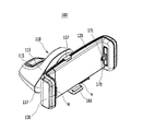
図1は、本発明の実施形態にかかる車両用スマートフォン据置台が車両に付着した状態を示す概略図であり、図2は、本発明の実施形態にかかる車両用スマートフォン据置台の斜視図であり、図3は、本発明の実施形態にかかる車両用スマートフォン据置台に適用される移動ユニットの構成図であり、図4は、本発明の実施形態にかかる車両用スマートフォン据置台に適用される充電ユニットの斜視図であり、図5は、図1のA−A線に沿った部分断面図である。 FIG. 1 is a schematic view showing a state in which a vehicle smartphone gantry according to an embodiment of the present invention is attached to a vehicle, and FIG. 2 is a perspective view of the vehicle smartphone gantry according to an embodiment of the present invention. FIG. 3 is a configuration diagram of a moving unit applied to the vehicle smartphone gantry according to the embodiment of the present invention, and FIG. 4 illustrates charging applied to the vehicle smartphone gantry according to the embodiment of the present invention. 5 is a perspective view of the unit, and FIG. 5 is a partial cross-sectional view taken along line AA in FIG.
図面を参照すれば、本発明の実施形態にかかる車両用スマートフォン据置台100は、センターフェイシアパネル3に設けられたドッキング部5を介して直接車両に装着され、製造会社ごとに多様な大きさおよび形状に形成されたスマートフォン10と多様な形状を有する充電端子に対応して充電コネクタ171を切り替えることができ、保護カバー11の厚さによって充電端子との間で発生するギャップに関係なく共用でスマートフォンを据え置くことができるようにする。
Referring to the drawings, a vehicular smartphone stationary table 100 according to an embodiment of the present invention is directly mounted on a vehicle via a
このために、本発明の実施形態にかかる車両用スマートフォン据置台100は、図1〜図3に示しているように、車両の室内において、センターフェイシアパネル3に形成され、電源端子4が備えられたドッキング部5に装着される。前記スマートフォン据置台100は、支持台110と、クレードル120と、支持クレードル130と、移動ユニット140と、充電ユニット170とを含む。
For this purpose, the smartphone mounting table 100 according to the embodiment of the present invention is formed on the
ここで、前記ドッキング部5には、支持台110を分離する場合、埃や異物などが電源端子4に流入するのを防止し、かつセンターフェイシアパネル3で外部に露出するのを防止するように、カバー7が着脱可能に装着されてよい。
Here, when the
つまり、使用者は、ドッキング部5にスマートフォン据置台100を装着する場合、カバー7をドッキング部5から分離し、スマートフォン据置台100を装着しない場合には、ドッキング部5にカバー7を装着する。
That is, the user separates the
本実施形態において、前記支持台110は、前記ドッキング部5に着脱可能に装着され、前記電源端子4に対応して下面に電源ピン111が備えられる。
In the present embodiment, the
本明細書において、支持台110の「下面」とは、ドッキング部5に対応する一面を意味し、支持台110の「上面」とは、前記「下面」の反対面を意味し、支持台110の「正面」とは、クレードル120の装着される面を意味する。
In this specification, the “lower surface” of the support table 110 means one surface corresponding to the
このような支持台110は、ボディ部113と、リリースボタン115と、固定フック117とを含んで構成される。
Such a
まず、前記ボディ部113は、前記ドッキング部5に対応する下面に前記電源ピン111が備えられる。
First, the
ここで、電源ピン111は、前記ボディ部113の内部を通過して前記クレードル120の内側に形成された連結端子121と電線を介して電気的に連結されてよい。
Here, the
前記リリースボタン115は、ボディ部113の上面に備えられ、前記固定フック117は、少なくとも1つ以上が備えられており、前記リリースボタン115の作動により、前記ボディ部113の下面でスライド移動可能に構成される。
The
このような固定フック117は、前記ドッキング部5に形成されるフック溝9に挿入され、前記ボディ部113の下面を前記ドッキング部5に固定させる。
Such a fixing
例えば、3つの固定フック117は、前記電源ピン111を囲む、設定された三角形状に配置されてよい。本明細書では、3つの固定フック117が備えられたことを例示したが、これに限定されない。設計者は、設計意図に合わせて固定フック117の個数および配置を選択することができる。
For example, the three fixing
本実施形態において、前記クレードル120は、前記支持台110の正面に、左右方向および上下方向に一定角度だけチルティング回転が可能となるように、その後面が装着される。
In this embodiment, the rear surface of the
つまり、前記クレードル120の後面中央は、半球形状に形成され、前記支持台110のボディ部113の正面に装着されている。したがって、運転者または使用者が支持台110を中心として前記クレードル120を選択的に回転させ、スマートフォンの角度を視野に合わせて変更することができる。
That is, the center of the rear surface of the
前記支持クレードル130は、前記クレードル120の一端に配置され、スマートフォン10の一端を支持する。
The
ここで、前記支持クレードル130は、前記スマートフォン10に対応する内側面に滑り止め部材Hが装着されてよい。
Here, the
前記滑り止め部材Hは、ゴム素材で製作されてよいし、スマートフォン10の一端を前記支持クレードル130に安定的にホールディングさせると同時に、車両の走行時に発生する振動や衝撃力を吸収してスマートフォン10が支持クレードル130から離脱するのを防止する機能を果たす。
The anti-slip member H may be made of a rubber material, and one end of the
図3に示されているように、前記移動ユニット140は、前記クレードル120の内部に設けられ、前記スマートフォン10の大きさに対応して、前記支持クレードル130を前記クレードル120の一端から選択的にスライド移動させる。
As shown in FIG. 3, the moving
ここで、前記移動ユニット140は、第1および第2スライダ141、143と、第1弾性部材145と、ダンパ147と、上下移動手段160とを含んで構成される。
Here, the moving
まず、前記第1および第2スライダ141、143のそれぞれは、前記クレードル120の内部で相互離隔した位置に長さ方向に形成されたレール溝142に沿ってスライド移動可能に装着され、その一端は前記支持クレードル130に連結され、その他端にはガイドロッド144が一体に形成される。
First, each of the first and
このような第1および第2スライダ141、143のそれぞれは、前記クレードル120の内部中央で前記レール溝142に対応して形成されるガイダ149によって前記レール溝142から離脱が防止され、レール溝142に沿ってスライド移動できる。
Each of the first and
本実施形態において、前記第1弾性部材145は、前記第1および第2スライダ141、143の各ガイドロッド144を囲んだ状態で、前記第1および第2スライダ141、143と前記クレードル120との間に介在して前記第1および第2スライダ141、143に弾性力を提供する。
In the present embodiment, the first
ここで、前記第1弾性部材145は、前記第1および第2スライダ141、143の各ガイドロッド144を囲んだ状態で、その一端が前記第1および第2スライダ141、143にそれぞれ支持され、その他端は前記クレードル120の内部によって支持されるコイルスプリングからなってよい。
Here, the first
このような第1弾性部材145は、前記第1および第2スライダ141、143に弾性力を提供することにより、前記クレードル120の内部でレール溝142に沿って第1および第2スライダ141、143をスライド移動させる。つまり、第1弾性部材145は、前記支持クレードル130をクレードル120から遠ざかるようにする弾性力を第1および第2スライダ141、143に提供する。
The first
前記ダンパ147は、前記クレードル120の内部で前記第1スライダ141の他側部に装着され、前記第1スライダ141の移動速度を制御する。
The
ここで、前記第1スライダ141は、前記ダンパ147に対応する他側部に長さ方向に沿ってギヤ列151が形成されてよい。
Here, the
また、前記ダンパ147には、前記ギヤ列151に対応して回転ギヤ153が回転可能に装着され、前記回転ギヤ153が前記ギヤ列151に噛み合うことができる。
A
これにより、前記第1スライダ141は、第1弾性部材145の弾性力によって、スライド移動時、回転ギヤ153を介してギヤ列151に噛み合ったダンパ147によって、レール溝142上でスムーズにスライド移動できる。
Accordingly, the
本実施形態において、前記第2スライダ143の他側部には、長さ方向に沿って一定間隔で複数の第1切欠155が形成できる。
In the present embodiment, a plurality of
そして、前記クレードル120には、第1切欠155に対応する位置に前記クレードル120の上部外側に向かって突出した状態で、上下部にスライド移動可能に装着され、前記第1切欠155に係止されて前記第2スライダ143の移動を制限する第1ロッカ157がさらに備えられてよい。
The
前記第1ロッカ157は、前記第1切欠155に対応する一側部に複数の第1係止突起158が形成される。これにより、前記第1ロッカ157は、前記第1係止突起158が前記第1切欠155に挿入されてロッキングされ、使用者が外部に突出した他端部を押す場合、前記第1切欠155からアンロッキングされてよい。
The
このような第1ロッカ157の前記第1スライダ141に向かう一端と、前記クレードル120の内部に形成された支持ブロック156との間には、第2弾性部材159が介在できる。前記第2弾性部材159は、前記第1ロッカ157を上部に押す弾性力を第1ロッカ157に提供する。
A second
前記第2弾性部材159は、支持ブロック156にその一端が支持された状態で、前記第1ロッカ157をクレードル120の外部に常に突出させる弾性力を提供することにより、複数の第1係止突起158が第1切欠155に係止された状態を維持できるようにする。
The second
使用者が前記第1ロッカ157を押すと、クレードル120の内部で第1弾性部材145によって第1および第2スライダ141、143が一側に押されることにより、クレードル120から支持クレードル130が遠ざかるように移動する。
When the user pushes the
この状態で、スマートフォン10の一端に支持クレードル130が接触するように、使用者は支持クレードル130を他側に押すことになる。
In this state, the user pushes the
この場合、支持クレードル130は、滑り止め部材Hを介してスマートフォン10に接触した状態で、第1ロッカ157の第1係止突起158が第2弾性部材159の弾性力によって第1切欠155に係止された状態となる。これにより、支持クレードル130は、クレードル120に固定される。
In this case, in the state where the
このような作動により、スマートフォン10は、クレードル120の前方でその一端部が支持クレードル130に固定できる。
By such an operation, the
そして、前記上下移動手段160は、前記第1および第2スライダ141、143とは関係なく上下部にスライド移動可能にクレードル120の内部中央に装着され、クレードル120の外部に突出した上下移動手段160の端部が前記スマートフォン10の下面を支持する。
The vertical movement means 160 is mounted at the center of the
このような上下移動手段160は、上下スライダ161と、第3弾性部材163と、第2切欠165と、第2ロッカ167と、第4弾性部材169とを含む。
Such vertical movement means 160 includes a
まず、前記上下スライダ161は、前記クレードル120の内部で前方中央に配置され、その下端がクレードル120の下部外側に突出した状態で、上下方向にスライド移動可能に装着される。
First, the up / down
ここで、前記上下スライダ161は、スマートフォン10の下面に対応する下部上面に滑り止め部材Hが装着されてよい。
Here, the upper and
前記滑り止め部材Hは、ゴム素材で製作されてよいし、スマートフォン10の下面を上下スライダ161に安定的にホールディングさせると同時に、車両の走行時に発生する振動や衝撃力を吸収してスマートフォン10が上下スライダ161から離脱するのを防止する機能を果たす。
The anti-slip member H may be made of a rubber material, and the
本実施形態において、前記第3弾性部材163は、前記クレードル120の内部後方に装着され、前記上下スライダ161に弾性力を提供する。
In the present embodiment, the third
このような第3弾性部材163は、その一端が前記クレードル120の後方によって支持され、その他端が上下スライダ161の上端部によって支持されるコイルスプリングから形成されてよい。
The third
前記第2切欠165は、前記上下スライダ161の一側に長さ方向に沿って形成される。
The
本実施形態において、前記第2ロッカ167は、前記第2切欠165に対応する位置においてクレードル120の長さ方向に沿ってスライド移動可能に設けられ、第2切欠165に対応する第2ロッカ167の一側には複数の第2係止突起168が形成される。
In the present embodiment, the
このような第2ロッカ167は、第2切欠に選択的に挿入される第2係止突起168を介して上下スライダ161の移動を制限する。
Such a
そして、前記第4弾性部材169は、前記クレードル120と前記第2ロッカ167との間に介在して前記第2ロッカ167に弾性力を提供する。
The fourth
このような第4弾性部材169は、その一端が第2ロッカ167に支持され、その他端はクレードル120の内部に支持されるコイルスプリングからなってよい。
The fourth
つまり、前記第2ロッカ167の一側に形成された複数の第2係止突起168が、第4弾性部材169の提供する弾性力によって上下スライダ161に形成された第2切欠165に挿入されると、前記第2ロッカ167は、前記上下スライダ161にロッキングされて上下スライダ161の移動を制限する。
That is, the plurality of second locking
クレードル120を下部に移動させるために、上下スライダ161をアンロッキングする場合には、使用者が第2ロッカ167を第2切欠165の反対側に移動させることにより、第2係止突起168を第2切欠165から離脱させる。この場合、第3弾性部材163の弾性力によって上下スライダ161がクレードル120の下部にスライド移動する。
When unlocking the upper and
クレードル120の下部に移動した上下スライダ161を再び元に位置させる場合には、使用者がクレードル120の下部に突出した上下スライダ161をクレードル120の上部に向かって適切な力で押すことになる。
When the upper and
すると、上下スライダ161は、第2切欠165と第2係止突起168が接触した状態で、上部に移動する。この時、第4弾性部材169は、第2切欠165と第2係止突起168によって発生する第2ロッカ167の移動量を吸収する。
Then, the
つまり、前記第4弾性部材169は、上下スライダ161が元の位置に復帰する時に発生する第2ロッカ167の移動量を吸収すると同時に、元の位置に復帰した上下スライダ161を第2ロッカ167を介して固定させるように弾性力を提供する。したがって、複数の第2係止突起168は、第4弾性部材169を介して第2切欠165に常に係止された状態を維持する。
That is, the fourth
そして、前記充電ユニット170は、クレードル120の前面に向かって回転可能に前記クレードル120の他端内部に装着される。前記充電ユニット170は、前記クレードル120から分離可能である。充電ユニット170は、スマートフォン10の他端に備えられた充電端子に挿入される充電コネクタ171が備えられ、スマートフォン10の他端を前記クレードル120に固定させ、かつ前記電源端子4から供給された電源をスマートフォン10に供給してスマートフォン10内に装着されたバッテリを充電させる。
The charging
このような充電ユニット170は、図4と図5に示しているように、ハウジング173と、第5弾性部材175と、連結コネクタ177とをさらに含んで構成される。
As shown in FIGS. 4 and 5, the charging
まず、前記ハウジング173は、前記クレードル120の他端内部にその両端がヒンジ結合され、前記クレードル120に回転可能に挿入される。
First, the
前記第5弾性部材175は、ハウジング173の内部でスマートフォン10の充電端子に向かって移動可能に装着される前記充電コネクタ171に弾性力を提供する。
The fifth
このような第5弾性部材175は、その一端がハウジング173の内部に支持され、その他端は充電コネクタ171に支持されるコイルスプリングからなってよい。
The fifth
そして、前記連結コネクタ177は、ハウジング173の外部で充電コネクタ171と電線を介して連結され、クレードル120の内部に備えられ、電源ピン111と電線を介して連結された連結端子121に結合される。
The
ここで、前記充電コネクタ171は、充電端子に挿入される部分が、前記ハウジング173の内部でクレードル120の長さ方向に沿ってスライド移動可能に装着されてよい。
Here, the charging
このような充電コネクタ171は、製造会社および機種ごとに多様な形状および大きさを有するスマートフォン10の充電端子に対応して、その形状および大きさがそれぞれ異なって形成されてよい。
Such a charging
つまり、前記充電ユニット170には、前記スマートフォン10の充電端子の形状および大きさによって、それぞれ異なる形状および大きさを有する充電コネクタ171がそれぞれ備えられてよいし、使用者の使用するスマートフォン10の仕様による充電端子に合わせて前記充電ユニット170を切り替えてクレードル120に装着することができる。
That is, the charging
本実施形態において、前記クレードル120は、充電ユニット170の装着される他端部の後方に後方カバー123が分離可能に装着されてよい。
In the present embodiment, the
前記後方カバー123は、充電コネクタ171の後端に対応するその内側にストッパ125が一体に突出して形成される。充電ユニット170がクレードル120の前方に向かって回転する場合、ストッパ125に充電コネクタ171の後端が係止されてハウジング173の回転範囲を制限する。
The
図6は、本発明の実施形態にかかる車両用スマートフォン据置台において充電ユニットの作動を示す概略図である。 FIG. 6 is a schematic view showing the operation of the charging unit in the vehicle smart phone gantry according to the embodiment of the present invention.
スマートフォン10が装着された状態の場合、前記充電ユニット170は、図6の(S1)のように、後方カバー123のストッパ125と平行に配置された状態を維持する。
When the
ここで、スマートフォン10に保護カバー11が装着された場合には、ハウジング173の内部で充電コネクタ171が後方カバー123に向かって押される。この時、充電コネクタ171の後端が後方カバー123の内側に支持されてよい。
Here, when the
スマートフォン10をスマートフォン据置台100に据え置く場合、図6の(S2)のように、使用者がまず、スマートフォン10の充電端子に充電コネクタ171を挿入させる。この時、ハウジング173は、クレードル120の前面に向かって一定角度回転する。
When the
ここで、前記ストッパ125は、ハウジング173によって回転した充電コネクタ171の下端に接触し、充電コネクタ171が設定角度以上回転するのを防止する。したがって、充電ユニット170のハウジング173も設定角度以上に回転することが制限される。
Here, the
これにより、使用者は、クレードル120の前方に一定角度回転した充電コネクタ171にスマートフォン10の充電端子をより円滑に挿入することができる。
Accordingly, the user can more smoothly insert the charging terminal of the
充電コネクタ171にスマートフォン10の充電端子を挿入した後、使用者は、スマートフォン10の一端部を支持クレードル130に向かって回転させることにより、充電ユニット170を再び図6の(S1)のような初期状態に復帰させる。
After inserting the charging terminal of the
つまり、充電ユニット170は、クレードル120の他端内部に回転可能に装着されることにより、使用者がより手軽にスマートフォン10の充電端子を充電コネクタ171に連結できるようにする。また、後方カバー123に備えられたストッパ125を介して充電ユニット170を設定範囲内でのみ回転させることにより、使用者の便宜性を向上させるのである。
That is, the charging
本発明の実施形態にかかる車両用スマートフォン据置台100を用いると、センターフェイシアパネル3に設けられたドッキング部5を介してスマートフォン据置台100を車両に装着することができ、ドッキング部5に含まれている電源端子4を介して電源が供給されるようにすることにより、別の電源ラインを除去することができて、車両室内の美観を向上させることができる。
If the
また、スマートフォン10の長さ方向に沿って移動可能な移動ユニット140を介して、スマートフォン10の大きさに合わせて支持クレードル130を選択的に移動させるように構成することにより、多様な形状および大きさを有するスマートフォン10に共用で使用することができる。
In addition, by configuring the
さらに、製造会社ごとに多様な大きさおよび形状に形成された充電端子を有するスマートフォン10に対応して、多様な大きさおよび形状に形成された充電コネクタ171を切替可能に構成することにより、充電端子の形状に応じてスマートフォン10ごとにスマートフォン据置台100を購入する場合に発生し得る費用を低減することができる。
Further, the charging
なおさらに、スマートフォン10に保護カバー11が装着されていても、移動可能に装着された充電コネクタ171を介してスマートフォン10を充電ユニット170に安定的に連結することができる。また、充電ユニット170がクレードル120に回転可能に装着され、スマートフォン10をより円滑で便利に据え置くことができる。したがって、使用性および便宜性を向上させることができる。
Furthermore, even if the
以上、本発明は、限定された実施形態と図面によって説明されたが、本発明は、これによって限定されず、本発明の属する技術分野における通常の知識を有する者によって本発明の技術思想および以下に記載される特許請求の範囲の均等範囲内で多様な修正および変形が可能であることは当然である。 As described above, the present invention has been described with reference to the limited embodiments and drawings. It goes without saying that various modifications and variations are possible within the scope of the equivalent claims.
3:センターフェイシアパネル
4:電源端子
5:ドッキング部
7:カバー
9:フック溝
10:スマートフォン
11:保護カバー
100:スマートフォン据置台
110:支持台
111:電源ピン
113:ボディ部
115:リリースボタン
117:固定フック
120:クレードル
121:連結端子
123:後方カバー
125:ストッパ
130:支持クレードル
140:移動ユニット
141、143:第1、第2スライダ
142:レール溝
144:ガイドロッド
145:第1弾性部材
147:ダンパ
149:ガイダ
151:ギヤ列
153:回転ギヤ
155:切欠
156:支持ブロック
157:ロッカ
158:係止突起
159:第2弾性部材
160:上下移動手段
161:上下スライダ
163:第3弾性部材
165:第2切欠
167:第2ロッカ
168:第2係止突起
169:第4弾性部材
170:充電ユニット
171:充電コネクタ
173:ハウジング
175:第5弾性部材
177:連結コネクタ
H:滑り止め部材
3: Center fascia panel 4: Power supply terminal 5: Docking part 7: Cover 9: Hook groove 10: Smartphone 11: Protective cover 100: Smartphone stand 110: Support base 111: Power supply pin 113: Body part 115: Release button 117: Fixed hook 120: Cradle 121: Connection terminal 123: Back cover 125: Stopper 130: Support cradle 140: Moving
Claims (19)
前記ドッキング部に着脱可能に装着され、前記電源端子に対応して下面に電源ピンが備えられた支持台と、
前記支持台の正面に装着される後面が備えられたクレードルと、
前記クレードルの一端に配置され、スマートフォンの一端を支持可能な支持クレードルと、
前記クレードルの内部に設けられ、前記スマートフォンの大きさに対応して、前記支持クレードルを前記クレードルの一端から選択的にスライド移動させる移動ユニットと、
前記クレードルの前面に向かって回転可能に前記クレードルの他端内部に装着され、前記スマートフォンの他端に備えられた充電端子に挿入される充電コネクタが備えられた充電ユニットとを含み、
前記移動ユニットは、前記クレードルの内部で相互離隔した位置に長さ方向に形成されたレール溝に沿ってスライド移動可能に装着され、前記支持クレードルに連結される一端とガイドロッドが一体に形成された他端とを備える第1スライダおよび第2スライダを含み、
前記第1スライダおよび前記第2スライダのそれぞれは、前記クレードルの中央内部で前記レール溝に対応して形成されるガイダによって前記レール溝から離脱が防止され、レール溝に沿ってスライド移動することを特徴とする、車両用スマートフォン据置台。 A docking portion formed on the vehicle inner panel and provided with a power terminal;
A support base that is detachably attached to the docking portion and has a power pin on the lower surface corresponding to the power terminal;
A cradle with a rear surface mounted on the front surface of the support base;
A support cradle disposed at one end of the cradle and capable of supporting one end of the smartphone;
A moving unit that is provided inside the cradle and selectively slides the support cradle from one end of the cradle according to the size of the smartphone;
Wherein toward the front of the cradle is mounted on the other end inside the rotatably the cradle, seen including a charging unit for charging connector is provided to be inserted into the charging terminal provided to the other end of the smart phone,
The moving unit is slidably mounted along a rail groove formed in a longitudinal direction at positions separated from each other inside the cradle, and one end connected to the support cradle and a guide rod are integrally formed. A first slider and a second slider with the other end,
Each of the first slider and the second slider is prevented from being detached from the rail groove by a guider formed corresponding to the rail groove inside the center of the cradle, and slides along the rail groove. A feature of the smartphone stand for vehicles.
前記第1スライダおよび前記第2スライダの各ガイドロッドを囲んだ状態で、前記第1スライダおよび前記第2スライダと前記クレードルとの間に介在して前記第1スライダおよび前記第2スライダに弾性力を提供する第1弾性部材と、
前記クレードルの内部で前記第1スライダの他側部に装着され、前記第1スライダの移動速度を制御するダンパと、
前記クレードルの内部中央に上下部にスライド移動可能に装着され、前記クレードルの外部に突出した端部を備え、前記端部が前記スマートフォンの下面を支持する上下移動手段とを含むことを特徴とする、請求項1に記載の車両用スマートフォン据置台。 The mobile unit,
Elastic in a state surrounding the respective guide rods before Symbol first slider and the second slider, the first slider and the second slider interposed between the first slider and the second slider and the cradle A first elastic member that provides force;
A damper that is mounted on the other side of the first slider inside the cradle and controls the moving speed of the first slider;
The cradle includes an end portion that is slidably mounted on the upper and lower portions of the cradle, includes an end portion that protrudes to the outside of the cradle, and the end portion includes a vertically moving means that supports a lower surface of the smartphone. The smartphone mounting table for vehicles according to claim 1.
前記クレードルの内部で前方に配置され、上下方向にスライド移動可能に装着される上下スライダと、
前記クレードルの内部後方に装着され、前記上下スライダに弾性力を提供する第3弾性部材と、
前記上下スライダの一側に長さ方向に沿って形成される第2切欠と、
前記第2切欠に対応する位置において前記クレードルの長さ方向に沿ってスライド移動可能に設けられ、前記第2切欠に対応する一側に複数の第2係止突起が形成され、第2切欠に選択的に挿入される前記第2係止突起を介して前記上下スライダの移動を制限する第2ロッカと、
前記クレードルと前記第2ロッカとの間に介在して前記第2ロッカに弾性力を提供する第4弾性部材とを含むことを特徴とする、請求項2に記載の車両用スマートフォン据置台。 The vertical movement means is
An upper and lower slider which is disposed forward in the cradle and is slidably mounted in the vertical direction;
A third elastic member mounted on the inner rear side of the cradle and providing elastic force to the upper and lower sliders;
A second notch formed along a length direction on one side of the upper and lower sliders;
A slidable movement is provided along a length direction of the cradle at a position corresponding to the second notch, and a plurality of second locking protrusions are formed on one side corresponding to the second notch, and the second notch A second rocker that restricts the movement of the upper and lower sliders through the second locking protrusions that are selectively inserted;
The vehicle smartphone mounting table according to claim 2, further comprising a fourth elastic member interposed between the cradle and the second rocker and providing an elastic force to the second rocker.
前記ドッキング部に対応する下面に前記電源ピンが備えられるボディ部と、
前記ボディ部の上面に備えられるリリースボタンと、
前記リリースボタンの作動により、前記ボディ部の下面でスライド移動可能に構成され、前記ドッキング部に形成されるフック溝に挿入され、前記ボディ部の下面を前記ドッキング部に固定させる少なくとも1つ以上の固定フックとを含むことを特徴とする、請求項1に記載の車両用スマートフォン据置台。 The support base is
A body part provided with the power pin on the lower surface corresponding to the docking part;
A release button provided on the upper surface of the body part;
At least one or more at least one of which is configured to be slidable on the lower surface of the body part by operation of the release button, inserted into a hook groove formed in the docking part, and to fix the lower surface of the body part to the docking part The vehicle smart phone cradle according to claim 1, further comprising a fixing hook.
前記クレードルの他端内部にその両端がヒンジ結合され、前記クレードルに回転可能に挿入されるハウジングと、
前記ハウジングの内部で前記スマートフォンの充電端子に向かって移動可能に装着される前記充電コネクタに弾性力を提供する第5弾性部材と、
前記ハウジングの外部で前記充電コネクタと電線を介して連結され、前記クレードルの内部に備えられ、前記電源ピンと電線を介して連結された連結端子に結合される連結コネクタとを含むことを特徴とする、請求項1に記載の車両用スマートフォン据置台。 The charging unit is
A housing that is hinged at both ends inside the other end of the cradle and is rotatably inserted into the cradle;
A fifth elastic member for providing an elastic force to the charging connector movably mounted toward the charging terminal of the smartphone inside the housing;
The charging connector is connected to the charging connector outside the housing via an electric wire, and is provided inside the cradle, and includes a connecting connector coupled to a connecting terminal connected via the power pin and the electric wire. The smartphone mounting table for vehicles according to claim 1.
Applications Claiming Priority (2)
| Application Number | Priority Date | Filing Date | Title |
|---|---|---|---|
| KR1020140057983A KR101601112B1 (en) | 2014-05-14 | 2014-05-14 | Smart phone holder for vehicle |
| KR10-2014-0057983 | 2014-05-14 |
Publications (2)
| Publication Number | Publication Date |
|---|---|
| JP2015217937A JP2015217937A (en) | 2015-12-07 |
| JP6422741B2 true JP6422741B2 (en) | 2018-11-14 |
Family
ID=52023221
Family Applications (1)
| Application Number | Title | Priority Date | Filing Date |
|---|---|---|---|
| JP2014225114A Active JP6422741B2 (en) | 2014-05-14 | 2014-11-05 | Smartphone stand for vehicles |
Country Status (6)
| Country | Link |
|---|---|
| US (1) | US9432071B2 (en) |
| EP (1) | EP2944517B1 (en) |
| JP (1) | JP6422741B2 (en) |
| KR (1) | KR101601112B1 (en) |
| CN (1) | CN105083146B (en) |
| ES (1) | ES2667673T3 (en) |
Families Citing this family (39)
| Publication number | Priority date | Publication date | Assignee | Title |
|---|---|---|---|---|
| US10627706B2 (en) * | 2013-02-25 | 2020-04-21 | iOgrapher, LLC | Apparatus with adjustable chamber for different sized mobile devices that perform image capture |
| WO2016022840A1 (en) * | 2014-08-06 | 2016-02-11 | Johnson Controls Technology Company | Mobile device holder for use in a vehicle |
| KR101714275B1 (en) * | 2015-12-14 | 2017-03-08 | 현대자동차주식회사 | Mobile phone holding device of vehicle |
| JP6112495B1 (en) * | 2016-02-19 | 2017-04-12 | パナソニックIpマネジメント株式会社 | Hand strap for electronic devices |
| CN205579063U (en) * | 2016-04-29 | 2016-09-14 | 汉洋(博罗)电子有限公司 | Clamping device and fixture |
| ES2587285B2 (en) * | 2016-07-07 | 2017-04-12 | Aiklo Technologies, S.L. | Support system for mobile devices |
| USD836646S1 (en) * | 2016-07-14 | 2018-12-25 | Clarion Technologies, Inc. | Device mount for scanner |
| US10705566B2 (en) | 2016-09-09 | 2020-07-07 | Targus International Llc | Systems, methods and devices for native and virtualized video in a hybrid docking station |
| CN106385476B (en) * | 2016-11-30 | 2019-04-16 | 广东庄正电子科技股份有限公司 | A kind of Novel mobilephone support with charge function |
| DE102017107724B4 (en) | 2017-03-16 | 2022-05-25 | Hochschule Osnabrück | Cradle for a mobile device and method of making a cradle |
| CN107415845A (en) * | 2017-05-27 | 2017-12-01 | 重庆长安汽车股份有限公司 | A kind of chargeable support of automotive seat mobile phone or flat board |
| US11231448B2 (en) | 2017-07-20 | 2022-01-25 | Targus International Llc | Systems, methods and devices for remote power management and discovery |
| JP6974061B2 (en) * | 2017-07-31 | 2021-12-01 | 株式会社リットーメガネ | Smartphone mount |
| KR200489154Y1 (en) | 2017-09-01 | 2019-05-09 | 이창석 | Mobile terminal holder for vehicle |
| KR200488939Y1 (en) | 2017-09-11 | 2019-04-08 | 주식회사 엔알 | Portable Smart Device Holder For Vehicle |
| CN107632397B (en) * | 2017-10-16 | 2020-07-10 | 龙岩学院 | VR glasses of adjustable stadia based on thing networking |
| KR102256990B1 (en) * | 2017-11-07 | 2021-05-27 | 현대모비스 주식회사 | Mobile holding apparatus |
| KR20190056224A (en) | 2017-11-16 | 2019-05-24 | 최재운 | Vehicle Only Smartphone Charging cradle and Smart phone case |
| CN107948374A (en) * | 2017-12-11 | 2018-04-20 | 李童 | A kind of office mobile phone holding frame |
| US11292543B2 (en) * | 2017-12-15 | 2022-04-05 | Nite Ize, Inc. | Systems and methods for a mountable multi-positional device holder |
| CN108040157A (en) * | 2017-12-19 | 2018-05-15 | 北京微格互动科技股份有限公司 | Gravity handset bracket |
| KR20190076101A (en) | 2017-12-22 | 2019-07-02 | 이창석 | Holder for portable terminal |
| CN108413229A (en) * | 2018-03-29 | 2018-08-17 | 北京小米移动软件有限公司 | Hand-held holder |
| JP7077747B2 (en) * | 2018-04-26 | 2022-05-31 | トヨタ自動車株式会社 | Display holder |
| CN109484169A (en) * | 2018-11-07 | 2019-03-19 | 徐萍 | For promoting the structure of new-energy automobile safety |
| GB2594173B (en) * | 2018-12-19 | 2023-10-04 | Targus International Llc | Display and docking apparatus for a portable electronic device |
| US11360534B2 (en) | 2019-01-04 | 2022-06-14 | Targus Internatonal Llc | Smart workspace management system |
| US11017334B2 (en) | 2019-01-04 | 2021-05-25 | Targus International Llc | Workspace management system utilizing smart docking station for monitoring power consumption, occupancy, and usage displayed via heat maps |
| WO2020154426A1 (en) * | 2019-01-22 | 2020-07-30 | ACV Auctions Inc. | Vehicle audio capture and diagnostics |
| CN110025257A (en) * | 2019-05-24 | 2019-07-19 | 苏州市伟克斯电器有限公司 | Dust catcher accepting rack and dust suction device assembly |
| CA3148974A1 (en) | 2019-08-22 | 2021-02-25 | Targus International Llc | Systems and methods for participant-controlled video conferencing |
| BR112022004289A2 (en) | 2019-09-09 | 2022-08-09 | Targus International Llc | SYSTEMS AND METHODS FOR REMOVABLELY FIXABLE DOCKING STATIONS TO DISPLAY APPARATUS AND ANCHORING SUPPORT ASSEMBLIES |
| USD943569S1 (en) * | 2020-02-28 | 2022-02-15 | Ugreen Group Limited | Electronic device mount for vehicles |
| KR102226682B1 (en) * | 2020-03-27 | 2021-03-11 | (주)모란카노코리아 | Strip type handle for phone |
| NZ777051A (en) * | 2020-06-27 | 2024-02-23 | Lorenzo Maggiore | Cell phone mount for bug killing guns |
| CN113450837B (en) * | 2021-07-16 | 2022-05-06 | 吕光金 | Safety protection device of external mobile hard disk of computer |
| KR200496841Y1 (en) * | 2021-10-28 | 2023-05-11 | 주식회사 쓰리아이 | Device cradle |
| US11783851B2 (en) | 2021-12-23 | 2023-10-10 | ACV Auctions Inc. | Multi-sensor devices and systems for evaluating vehicle conditions |
| KR102430246B1 (en) * | 2022-03-31 | 2022-08-05 | 최성현 | Smartphone charging cradle with detachable cable charging terminal |
Family Cites Families (22)
| Publication number | Priority date | Publication date | Assignee | Title |
|---|---|---|---|---|
| JPH11310088A (en) * | 1998-04-20 | 1999-11-09 | Ichita Kawashima | Cigar lighter charger attached with portable telephone holder |
| KR20000010145A (en) * | 1998-07-30 | 2000-02-15 | 윤종용 | Pre-engaged recording device of a digital broadcasting system and a pre-engaged recording method thereof |
| JP2000115315A (en) * | 1998-09-30 | 2000-04-21 | Harness Syst Tech Res Ltd | Telephone set holder |
| KR200203677Y1 (en) | 1998-11-17 | 2000-12-01 | 민경훈 | A stand for handy-phone using in a car |
| KR200197071Y1 (en) * | 2000-04-10 | 2000-09-15 | 주식회사캄코 | Automatic turing on and off device for emergency light of vehicle |
| KR200215028Y1 (en) * | 2000-09-18 | 2001-02-15 | 최기범 | a hands free system for car |
| KR200261161Y1 (en) * | 2001-11-01 | 2002-01-19 | 주식회사 자티전자 | a hands free cradle of a phone |
| US20060105819A1 (en) | 2004-11-12 | 2006-05-18 | Bryant Liao | Portable electronic device's docking cradle on vechicle |
| EP1842356B1 (en) | 2005-01-24 | 2013-02-27 | Core Wireless Licensing S.a.r.l. | Cradle for mobile phones |
| KR100625699B1 (en) * | 2005-07-06 | 2006-09-20 | 이호상 | Spin stand for cellular phone case |
| FR2902383A3 (en) | 2006-06-16 | 2007-12-21 | Northstar Systems Corp | Electronic apparatus e.g. cellular phone, locking device for motor vehicle, has spring placed between seat body and locking elements, barrier element with barrier surface coming in contact with contact surface of rotating wheel |
| CN200956487Y (en) * | 2006-09-30 | 2007-10-03 | 番禺得意精密电子工业有限公司 | Electric connector |
| KR100811950B1 (en) * | 2006-12-05 | 2008-03-10 | 현대자동차주식회사 | Upper tray for vehicle |
| CN201115172Y (en) * | 2007-07-27 | 2008-09-10 | 佛山市顺德区顺达电脑厂有限公司 | A supporting rack and its auxiliary instrument board structure |
| JP5242497B2 (en) * | 2009-05-13 | 2013-07-24 | 株式会社ニフコ | Goods holder |
| US8202114B2 (en) * | 2009-12-14 | 2012-06-19 | Mitac International Corp. | Mobile phone cradle with three-point retention of portable electronic device installed in the cradle |
| KR101239024B1 (en) * | 2010-10-12 | 2013-03-04 | 장애인표준사업장비클시스템 주식회사 | Multimedia terminal holding apparatus for vehicle |
| CN201900841U (en) * | 2010-12-23 | 2011-07-20 | 周丹涛 | Name card case and bracket for taking pictures of name cards by using mobile phone |
| KR20130012746A (en) | 2011-07-26 | 2013-02-05 | 주식회사대성엘텍 | Portable terminal cradle of car multi media aii in one type |
| JP2013091334A (en) * | 2011-10-24 | 2013-05-16 | Sony Corp | Connection device |
| US8926349B2 (en) | 2012-02-23 | 2015-01-06 | Jeffrey D. Carnevali | Universal adaptor mount for a docking station |
| US9468122B2 (en) | 2013-03-13 | 2016-10-11 | Ford Global Technologies, Llc | Portable device holding apparatus |
-
2014
- 2014-05-14 KR KR1020140057983A patent/KR101601112B1/en active IP Right Grant
- 2014-11-05 JP JP2014225114A patent/JP6422741B2/en active Active
- 2014-12-01 US US14/557,274 patent/US9432071B2/en active Active
- 2014-12-03 ES ES14196041.9T patent/ES2667673T3/en active Active
- 2014-12-03 EP EP14196041.9A patent/EP2944517B1/en active Active
- 2014-12-31 CN CN201410851713.9A patent/CN105083146B/en active Active
Also Published As
| Publication number | Publication date |
|---|---|
| KR101601112B1 (en) | 2016-03-08 |
| JP2015217937A (en) | 2015-12-07 |
| ES2667673T3 (en) | 2018-05-14 |
| EP2944517A1 (en) | 2015-11-18 |
| KR20150130842A (en) | 2015-11-24 |
| CN105083146A (en) | 2015-11-25 |
| CN105083146B (en) | 2020-10-20 |
| EP2944517B1 (en) | 2018-02-14 |
| US20150333789A1 (en) | 2015-11-19 |
| US9432071B2 (en) | 2016-08-30 |
Similar Documents
| Publication | Publication Date | Title |
|---|---|---|
| JP6422741B2 (en) | Smartphone stand for vehicles | |
| KR101500380B1 (en) | Smart phone holder for vehicle | |
| US9008736B2 (en) | Protective frame for mobile communication device | |
| US9296325B2 (en) | Vehicle USB port | |
| EP2209289B1 (en) | Universal holder for handheld electronic device | |
| KR101000038B1 (en) | A support for electronic equipment in car | |
| KR101236895B1 (en) | Holder for mobile phone | |
| KR101219760B1 (en) | Fixing device for portable instrument | |
| KR200477762Y1 (en) | Cradle of smart phone | |
| KR20160001328A (en) | Device for holding a portable phone having wireless charging function | |
| KR101097520B1 (en) | Deposit Unit for Cell phone and Automobile including the same | |
| KR20140069684A (en) | A mobile phone mount for vehicles | |
| KR200488939Y1 (en) | Portable Smart Device Holder For Vehicle | |
| JP2013043626A (en) | Vehicular portable device holder | |
| US11661015B2 (en) | Holding mechanism and holding device | |
| KR101704295B1 (en) | Cell phone supporter for wireless rechargable of vehicle | |
| JP2012224237A (en) | Fitting structure of smartphone | |
| KR20140002951U (en) | Mobile phone case with a stand | |
| KR200398399Y1 (en) | Cellular phone charging holder for a car | |
| KR200474320Y1 (en) | Holder for portable electronic equipment | |
| KR101987153B1 (en) | Smart phone holder for vehicle | |
| CN220518152U (en) | Vehicle-mounted storage device | |
| CN220639719U (en) | Duplex screen structure integrating wireless charging function of mobile phone | |
| CN220615682U (en) | Fixed bolster, well accuse platform assembly and vehicle | |
| KR101550266B1 (en) | Folder type holder for vehicle with adjustable length |
Legal Events
| Date | Code | Title | Description |
|---|---|---|---|
| RD03 | Notification of appointment of power of attorney |
Free format text: JAPANESE INTERMEDIATE CODE: A7423 Effective date: 20161124 |
|
| A621 | Written request for application examination |
Free format text: JAPANESE INTERMEDIATE CODE: A621 Effective date: 20170613 |
|
| A131 | Notification of reasons for refusal |
Free format text: JAPANESE INTERMEDIATE CODE: A131 Effective date: 20180522 |
|
| A521 | Request for written amendment filed |
Free format text: JAPANESE INTERMEDIATE CODE: A523 Effective date: 20180815 |
|
| TRDD | Decision of grant or rejection written | ||
| A01 | Written decision to grant a patent or to grant a registration (utility model) |
Free format text: JAPANESE INTERMEDIATE CODE: A01 Effective date: 20180921 |
|
| A61 | First payment of annual fees (during grant procedure) |
Free format text: JAPANESE INTERMEDIATE CODE: A61 Effective date: 20181017 |
|
| R150 | Certificate of patent or registration of utility model |
Ref document number: 6422741 Country of ref document: JP Free format text: JAPANESE INTERMEDIATE CODE: R150 |
|
| R250 | Receipt of annual fees |
Free format text: JAPANESE INTERMEDIATE CODE: R250 |
|
| R250 | Receipt of annual fees |
Free format text: JAPANESE INTERMEDIATE CODE: R250 |
|
| R250 | Receipt of annual fees |
Free format text: JAPANESE INTERMEDIATE CODE: R250 |