JP6410062B2 - Imaging device and display method of captured image - Google Patents
Imaging device and display method of captured image Download PDFInfo
- Publication number
- JP6410062B2 JP6410062B2 JP2017040423A JP2017040423A JP6410062B2 JP 6410062 B2 JP6410062 B2 JP 6410062B2 JP 2017040423 A JP2017040423 A JP 2017040423A JP 2017040423 A JP2017040423 A JP 2017040423A JP 6410062 B2 JP6410062 B2 JP 6410062B2
- Authority
- JP
- Japan
- Prior art keywords
- image
- shake
- screen
- correction
- amount
- Prior art date
- Legal status (The legal status is an assumption and is not a legal conclusion. Google has not performed a legal analysis and makes no representation as to the accuracy of the status listed.)
- Active
Links
Images


Classifications
-
- H—ELECTRICITY
- H04—ELECTRIC COMMUNICATION TECHNIQUE
- H04N—PICTORIAL COMMUNICATION, e.g. TELEVISION
- H04N23/00—Cameras or camera modules comprising electronic image sensors; Control thereof
- H04N23/60—Control of cameras or camera modules
- H04N23/68—Control of cameras or camera modules for stable pick-up of the scene, e.g. compensating for camera body vibrations
- H04N23/682—Vibration or motion blur correction
- H04N23/683—Vibration or motion blur correction performed by a processor, e.g. controlling the readout of an image memory
-
- G—PHYSICS
- G03—PHOTOGRAPHY; CINEMATOGRAPHY; ANALOGOUS TECHNIQUES USING WAVES OTHER THAN OPTICAL WAVES; ELECTROGRAPHY; HOLOGRAPHY
- G03B—APPARATUS OR ARRANGEMENTS FOR TAKING PHOTOGRAPHS OR FOR PROJECTING OR VIEWING THEM; APPARATUS OR ARRANGEMENTS EMPLOYING ANALOGOUS TECHNIQUES USING WAVES OTHER THAN OPTICAL WAVES; ACCESSORIES THEREFOR
- G03B17/00—Details of cameras or camera bodies; Accessories therefor
- G03B17/18—Signals indicating condition of a camera member or suitability of light
-
- G—PHYSICS
- G03—PHOTOGRAPHY; CINEMATOGRAPHY; ANALOGOUS TECHNIQUES USING WAVES OTHER THAN OPTICAL WAVES; ELECTROGRAPHY; HOLOGRAPHY
- G03B—APPARATUS OR ARRANGEMENTS FOR TAKING PHOTOGRAPHS OR FOR PROJECTING OR VIEWING THEM; APPARATUS OR ARRANGEMENTS EMPLOYING ANALOGOUS TECHNIQUES USING WAVES OTHER THAN OPTICAL WAVES; ACCESSORIES THEREFOR
- G03B5/00—Adjustment of optical system relative to image or object surface other than for focusing
-
- H—ELECTRICITY
- H04—ELECTRIC COMMUNICATION TECHNIQUE
- H04N—PICTORIAL COMMUNICATION, e.g. TELEVISION
- H04N23/00—Cameras or camera modules comprising electronic image sensors; Control thereof
- H04N23/60—Control of cameras or camera modules
- H04N23/63—Control of cameras or camera modules by using electronic viewfinders
- H04N23/631—Graphical user interfaces [GUI] specially adapted for controlling image capture or setting capture parameters
- H04N23/632—Graphical user interfaces [GUI] specially adapted for controlling image capture or setting capture parameters for displaying or modifying preview images prior to image capturing, e.g. variety of image resolutions or capturing parameters
-
- H—ELECTRICITY
- H04—ELECTRIC COMMUNICATION TECHNIQUE
- H04N—PICTORIAL COMMUNICATION, e.g. TELEVISION
- H04N23/00—Cameras or camera modules comprising electronic image sensors; Control thereof
- H04N23/60—Control of cameras or camera modules
- H04N23/68—Control of cameras or camera modules for stable pick-up of the scene, e.g. compensating for camera body vibrations
- H04N23/681—Motion detection
- H04N23/6811—Motion detection based on the image signal
-
- H—ELECTRICITY
- H04—ELECTRIC COMMUNICATION TECHNIQUE
- H04N—PICTORIAL COMMUNICATION, e.g. TELEVISION
- H04N23/00—Cameras or camera modules comprising electronic image sensors; Control thereof
- H04N23/60—Control of cameras or camera modules
- H04N23/68—Control of cameras or camera modules for stable pick-up of the scene, e.g. compensating for camera body vibrations
- H04N23/681—Motion detection
- H04N23/6812—Motion detection based on additional sensors, e.g. acceleration sensors
-
- H—ELECTRICITY
- H04—ELECTRIC COMMUNICATION TECHNIQUE
- H04N—PICTORIAL COMMUNICATION, e.g. TELEVISION
- H04N7/00—Television systems
- H04N7/18—Closed-circuit television [CCTV] systems, i.e. systems in which the video signal is not broadcast
Description
本発明は、撮像装置および撮像画像の表示方法に関し、より詳細には、撮像素子により複数のフレーム画像からなる撮像画像を時系列的に撮像する撮像装置および該撮像装置により撮像された撮像画像の表示方法に関する。 The present invention relates to an imaging device and a method for displaying a captured image. More specifically, the present invention relates to an imaging device that captures a captured image including a plurality of frame images in a time series using an imaging device, and a captured image captured by the imaging device. It relates to the display method.
従来、監視カメラが揺れたときに生じる撮像画像の画像揺れを補正することを目的として、振動検出手段(振動センサ)により監視カメラの揺れを検出し、検出された揺れ成分の解析結果に応じて、撮像画像の揺れ補正を行う揺れ補正手段に対して揺れ補正モードを指示するように構成した技術が知られている(特許文献1)。 Conventionally, for the purpose of correcting the image shake of the captured image that occurs when the surveillance camera shakes, the vibration of the surveillance camera is detected by the vibration detection means (vibration sensor), and according to the analysis result of the detected shake component There is known a technique configured to instruct a shake correction mode to a shake correction unit that performs shake correction of a captured image (Patent Document 1).
監視システムやテレビ放送システム等においては、例えば地震等の災害時には、被写体の揺れの程度を把握するために、画像揺れの補正を行わずに撮像画像をそのまま表示することが一般的に行われている。しかしながら、災害の詳細な状況を把握するためには、撮像画像の画像揺れを補正した揺れ補正画像を表示することが望ましい。これは、地震等の災害時に限らず、風や交通振動等に起因して撮像画像に画像揺れが生じた場合も同様である。 In a surveillance system or a television broadcasting system, for example, in the event of a disaster such as an earthquake, it is generally performed to display a captured image as it is without correcting image shaking in order to grasp the degree of shaking of the subject. Yes. However, in order to grasp the detailed situation of the disaster, it is desirable to display a shake correction image obtained by correcting the shake of the captured image. This is not limited to the case of a disaster such as an earthquake, but is the same when an image shake occurs in a captured image due to wind, traffic vibration, or the like.
本開示は、このような従来技術の課題を鑑みて案出されたものであり、撮像画像とその画像揺れを補正した揺れ補正画像との両方を同一画面上に表示することができる撮像装置および撮像画像の表示方法を提供することを主目的とする。 The present disclosure has been devised in view of the problems of the related art, and an imaging apparatus capable of displaying both a captured image and a shake-corrected image obtained by correcting the image shake on the same screen. The main object is to provide a method for displaying captured images.
本開示の撮像装置は、撮像素子により複数のフレーム画像からなる撮像画像を時系列的に撮像する撮像装置であって、該撮像装置の物理的揺れ量を検出する角速度センサと、前記物理的揺れ量に基づき現フレーム画像の画像揺れを補正するための補正量を算出する補正量算出部と、前記補正量に基づき前記現フレーム画像に対して幾何学的変換を施すことにより、前記画像揺れが補正された揺れ補正画像を生成する揺れ補正画像生成部と、前記現フレーム画像と前記揺れ補正画像とを同一画面上に配置した合成画像を生成する合成画像生成部と、前記補正画像生成部および前記合成画像生成部の各処理を制御する制御部と、を備え、前記制御部は、前記物理的揺れ量が一定値以上検出された場合に、前記合成画像の生成を行うことを特徴とする。 An imaging apparatus according to an embodiment of the present disclosure is an imaging apparatus that captures a captured image including a plurality of frame images in a time series using an imaging element, and includes an angular velocity sensor that detects a physical shake amount of the imaging apparatus, and the physical shake a correction amount calculation unit for calculating a correction amount for correcting the image shake of the current frame image based on the amount by performing geometric conversion on the current frame image based on the correction amount, the image shaking A shake correction image generation unit that generates a corrected shake correction image, a composite image generation unit that generates a composite image in which the current frame image and the shake correction image are arranged on the same screen , the correction image generation unit, and and a control unit for controlling the processing of the composite image generating unit, wherein, when the physical shake amount is detected more than a predetermined value, to and performing the generation of the composite image .
本開示によれば、物理的揺れ量が一定値以上検出された場合に、撮像画像とその画像揺れを補正した揺れ補正画像との両方を同一画面上に表示することが可能となる。 According to the present disclosure, it is possible to display both a captured image and a shake-corrected image obtained by correcting the image shake on the same screen when a physical shake amount is detected to be a certain value or more .
上記課題を解決するためになされた第1の発明は、撮像素子により複数のフレーム画像からなる撮像画像を時系列的に撮像する撮像装置であって、該撮像装置の物理的揺れ量を検出する角速度センサと、前記物理的揺れ量に基づき現フレーム画像の画像揺れを補正するための補正量を算出する補正量算出部と、前記補正量に基づき前記現フレーム画像に対して幾何学的変換を施すことにより、前記画像揺れが補正された揺れ補正画像を生成する揺れ補正画像生成部と、前記現フレーム画像と前記揺れ補正画像とを同一画面上に配置した合成画像を生成する合成画像生成部と、前記補正画像生成部および前記合成画像生成部の各処理を制御する制御部と、を備え、前記制御部は、前記物理的揺れ量が一定値以上検出された場合に、前記合成画像の生成を行うことを特徴とする。 A first invention made to solve the above-described problem is an imaging device that images a captured image composed of a plurality of frame images in a time series using an imaging device, and detects a physical shake amount of the imaging device. An angular velocity sensor; a correction amount calculation unit that calculates a correction amount for correcting image shake of the current frame image based on the physical shake amount; and geometric conversion for the current frame image based on the correction amount. A shake correction image generation unit that generates a shake correction image in which the image shake is corrected, and a composite image generation unit that generates a composite image in which the current frame image and the shake correction image are arranged on the same screen. And a control unit that controls each process of the corrected image generation unit and the composite image generation unit, and the control unit detects the composite image when the physical fluctuation amount is detected to be a predetermined value or more. And performing generation.
この第1の発明に係る撮像装置によれば、物理的揺れ量が一定値以上検出された場合に、現フレーム画像と揺れ補正画像とを同一画面上に配置した合成画像を生成することができるので、撮像画像とその画像揺れを補正した揺れ補正画像との両方を同一画面上に表示することが可能となる。 According to the imaging device of the first aspect of the present invention, when the physical shake amount is detected to be a certain value or more, a composite image in which the current frame image and the shake correction image are arranged on the same screen can be generated. Therefore, both the captured image and the shake correction image obtained by correcting the image shake can be displayed on the same screen.
また、第2の発明は、上記第1の発明において、前記合成画像は、親画面と該親画面上に配置された子画面とから構成されており、前記合成画像生成部は、前記現フレーム画像および前記揺れ補正画像の一方を前記親画面に配置し、他方を前記子画面に配置することを特徴とする。 In a second aspect based on the first aspect, the composite image is composed of a main screen and a sub-screen arranged on the main screen, and the composite image generation unit One of the image and the shake correction image is arranged on the parent screen, and the other is arranged on the child screen.
この第2の発明に係る撮像装置によれば、現フレーム画像および揺れ補正画像を親画面および子画面に配置することができるので、両画像を見やすく表示することが可能となる。 According to the image pickup apparatus of the second invention, the current frame image and the shake correction image can be arranged on the main screen and the sub screen, so that both images can be easily displayed.
また、第3の発明は、上記第1の発明において、前記合成画像生成部は、ユーザから入力される命令に従って、前記親画面および前記子画面の少なくとも一方の画面サイズ、ならびに前記親画面上における前記子画面の配置位置を変更可能であることを特徴とする。 According to a third aspect, in the first aspect, the composite image generation unit is configured to display at least one of the main screen size and the sub-screen size according to a command input from a user, and on the main screen. The arrangement position of the sub-screen can be changed.
この第3の発明に係る撮像装置によれば、親画面および子画面の画面サイズや子画面の配置位置をユーザの所望に応じて自由に変更することができる。 According to the imaging apparatus of the third aspect of the present invention, the screen size of the parent screen and the child screen and the arrangement position of the child screen can be freely changed according to the user's desire.
また、第4の発明は、上記第1の発明において、前記合成画像は、左右方向または上下方向に互いに並んで配置された第1画面および第2画面とから構成されており、前記合成画像生成部は、前記現フレーム画像および前記揺れ補正画像の一方を前記第1画面に配置し、他方を前記第2画面に配置することを特徴とする。 In a fourth aspect based on the first aspect, the composite image is composed of a first screen and a second screen arranged side by side in the horizontal direction or the vertical direction, and the composite image generation The unit arranges one of the current frame image and the shake correction image on the first screen and the other on the second screen.
この第4の発明に係る撮像装置によれば、現フレーム画像および揺れ補正画像を左右方向または上下方向に互いに並んで配置された第1画面および第2画面に配置することができるので、両画像を見やすく表示することが可能となる。 According to the imaging apparatus of the fourth aspect, the current frame image and the shake correction image can be arranged on the first screen and the second screen arranged side by side in the left-right direction or the up-down direction. Can be displayed in an easy-to-see manner.
また、第5の発明は、上記第4の発明において、前記合成画像生成部は、ユーザから入力される命令に従って、前記第1画面および前記第2画面の画面サイズを変更可能であることを特徴とする。 According to a fifth aspect, in the fourth aspect, the composite image generation unit can change a screen size of the first screen and the second screen in accordance with a command input from a user. And
この第5の発明に係る撮像装置によれば、第1画面および第2画面の画面サイズをユーザの所望に応じて自由に変更することができる。 According to the imaging device of the fifth aspect, the screen sizes of the first screen and the second screen can be freely changed according to the user's desire.
また、第6の発明は、撮像素子により複数のフレーム画像からなる撮像画像を時系列的に撮像する撮像装置であって、該撮像装置の物理的揺れ量を検出する角速度センサと、前記物理的揺れ量に基づき現フレーム画像の画像揺れを補正するための補正量を算出する補正量算出部と、前記補正量に基づきイメージセンサの光学系を制御して、前記画像揺れが補正された揺れ補正画像を生成する揺れ補正画像生成部と、前記補正量に基づき前記揺れ補正画像に対して幾何学的変換を施すことにより、前記画像揺れを含む揺れ画像を生成する揺れ画像生成部と、前記揺れ画像と前記揺れ補正画像とを同一画面上に配置した合成画像を生成する合成画像生成部と、を備えたことを特徴とする。 According to a sixth aspect of the present invention, there is provided an image pickup apparatus that picks up a picked-up image composed of a plurality of frame images in a time series using an image pickup element , the angular velocity sensor for detecting a physical fluctuation amount of the image pickup apparatus, and the physical A correction amount calculation unit for calculating a correction amount for correcting image shake of the current frame image based on the shake amount, and a shake correction in which the image shake is corrected by controlling the optical system of the image sensor based on the correction amount. A shake correction image generation unit that generates an image, a shake image generation unit that generates a shake image including the image shake by performing geometric transformation on the shake correction image based on the correction amount, and the shake And a composite image generation unit configured to generate a composite image in which the image and the shake correction image are arranged on the same screen .
この第6の発明に係る撮像装置によれば、補正量算出部で算出された補正量に基づきイメージセンサの光学系を制御して揺れ補正画像を生成すると共に、揺れ補正画像から撮像画像相当の揺れ画像を生成するので、撮像画像とその画像揺れを補正した揺れ補正画像との両方を同一画面上に表示することが可能となる。 According to the imaging apparatus of the sixth aspect of the invention, the shake correction image is generated by controlling the optical system of the image sensor based on the correction amount calculated by the correction amount calculation unit, and the image corresponding to the captured image is generated from the shake correction image. Since the shake image is generated, both the captured image and the shake correction image obtained by correcting the image shake can be displayed on the same screen .
また、第7の発明は、撮像素子により時系列的に撮像した複数のフレーム画像からなる撮像画像の表示方法であって、該撮像装置の物理的揺れ量を検出するステップと、前記物理的揺れ量に基づき現フレーム画像の画像揺れを補正するための補正量を算出するステップと、前記補正量に基づき前記現フレーム画像に対して幾何学的変換を施すことにより、前記画像揺れが補正された揺れ補正画像を生成するステップと、前記現フレーム画像と前記揺れ補正画像とを同一画面上に配置した合成画像を生成するステップと、前記揺れ補正画像の生成および前記合成画像の生成の各処理を制御するステップと、を有し、前記制御するステップは、前記物理的揺れ量が一定値以上検出された場合に、前記合成画像の生成を行うことを特徴とする。 According to a seventh aspect of the present invention, there is provided a method for displaying a picked-up image composed of a plurality of frame images picked up in time series by an image pickup device, the step of detecting a physical shake amount of the image pickup device, and the physical shake calculating a correction amount for correcting the image shake of the current frame image based on the amount by performing geometric conversion on the current frame image based on the correction amount, the image shake is corrected A step of generating a shake correction image, a step of generating a composite image in which the current frame image and the shake correction image are arranged on the same screen, a generation of the shake correction image, and a generation of the composite image And the step of controlling generates the composite image when the physical fluctuation amount is detected to be equal to or greater than a predetermined value .
この第7の発明に係る撮像画像の表示方法によれば、物理的揺れ量が一定値以上検出された場合に、現フレーム画像と揺れ補正画像とを同一画面上に配置した合成画像を生成することができるので、撮像画像とその画像揺れを補正した揺れ補正画像との両方を同一画面上に表示することが可能となる。 According to the method for displaying a captured image according to the seventh aspect of the invention, when a physical shake amount is detected to be equal to or greater than a certain value, a composite image in which the current frame image and the shake correction image are arranged on the same screen is generated. Therefore, both the captured image and the shake correction image obtained by correcting the shake of the image can be displayed on the same screen.
以下、本開示の実施形態について、図面を参照しながら説明する。 Hereinafter, embodiments of the present disclosure will be described with reference to the drawings.
本実施形態では、本開示に係る撮像装置1を監視カメラとして使用する場合について説明する。撮像装置1は、例えば電柱やポール等に取り付けられる。したがって、地震、風、交通振動等により電柱やポールが揺れた場合は、撮像装置1も揺れるため、撮像装置1により撮像された撮像画像に画像揺れが生じることとなる。
In the present embodiment, a case where the
(第1実施形態)
図1は、本開示の第1実施形態に係る撮像装置1の概略構成図である。撮像装置1は、ネットワーク3を介して、監視本部等に設置されたモニタ装置2(監視端末)に接続されている。撮像装置1は、ズームレンズを含むレンズ系11と、イメージセンサ12と、カメラ信号処理部13と、角速度センサ14と、補正量算出部15と、ネットワークインターフェース(I/F)16と、制御部17と、画像合成部18とを備えている。
(First embodiment)
FIG. 1 is a schematic configuration diagram of an
ズームレンズを含むレンズ系11は、被写体からの撮像光を集光し、イメージセンサ12の撮像面に結像させて被写体像を形成する。イメージセンサ12は、CMOS(Complementary Metal Oxide Semiconductor)であり、所定のフレーム周期(撮像周期)で、その撮像面に結像した被写体像を電気信号に変換する。カメラ信号処理部13は、イメージセンサ12で生成された画像信号に対して各種の信号処理を施し、フレーム画像(画像データ)を生成する。
A
撮像装置1が揺れて、撮像画像に画像揺れが生じた場合は、イメージセンサ12で生成されたフレーム画像は、画像揺れを含む揺れ画像となる。この第1実施形態では、イメージセンサ12で生成されたフレーム画像は、揺れ画像であるものとする。したがって、この第1実施形態では、イメージセンサ12は、揺れ画像を生成する揺れ画像生成部21と見なすことができる。
When the
角速度センサ14は、撮像装置1の角度が単位時間当たりどれだけ変化しているか、すなわち、物理的揺れ量を検出する。具体的には、撮像装置1の左右方向(パン方向)の回転角速度と、撮像装置1の上下方向(チルト方向)の回転角速度とをそれぞれ検出する。補正量算出部15は、角速度センサ14で検出された回転角速度に基づいて、現時点のフレーム(以降、「現フレーム」と称する)の画像揺れを補正するための補正量を算出する。
The
図2は、回転角速度と補正量との関係を説明するための図である。補正量算出部15は、現フレーム(フレームN)と前フレーム(フレームN−1)との間での、フレーム画像中の被写体の左右方向(x方向)および上下方向(y方向)の平均移動量(Δx、Δy)を求める。平均移動量(Δx、Δy)は、角速度センサ14の回転角速度を、従来公知の手法を用いて被写体のx方向およびy方向の変位量に換算することにより求めることができる。求められた平均移動量(Δx、Δy)が、現フレーム(フレームN)の補正量「Δx(N)、Δy(N)」となる。補正量算出部15で算出された補正量は画像合成部18に入力される。
FIG. 2 is a diagram for explaining the relationship between the rotational angular velocity and the correction amount. The correction
ネットワークI/F16は、撮像装置1をネットワーク3に接続するためのものである。ネットワークI/F16は、ネットワーク3を介してモニタ装置2から、撮像画像の揺れ補正を指示する命令や、画像合成方式を指示する命令を受信する。ネットワークI/F16がモニタ装置2から受信した命令は制御部17に入力される。また、ネットワークI/F16は、画像合成部18で生成された後述する合成画像33(図3参照)を、ネットワーク3を介してモニタ装置2に送信する。
The network I /
制御部17は、プロセッサで構成することができ、撮像画像の揺れ補正および合成画像の生成を含む撮像装置1の各処理を統括して制御するためのものであり、不図示のROM(Read only memory)に予め記憶された制御プログラムおよびネットワークI/F16から入力された各命令に基づき撮像装置1の各処理を制御する。
The
画像合成部18は、補正量算出部15で算出された補正量に基づき現フレームのフレーム画像に対して幾何学的変換を施すことにより、画像揺れが補正された揺れ補正画像を生成する揺れ補正画像生成部22と、揺れ画像と揺れ補正画像とを同一画面上に配置した合成画像33を生成する合成画像生成部23とを有している。
The
図3は、画像合成部18での処理を示す図であり、図4は、揺れ補正画像生成部22での幾何学的変換処理を説明するための図である。
FIG. 3 is a diagram illustrating processing in the
まず、揺れ補正画像生成部22は、カメラ信号処理部13から現フレーム(フレームN)のフレーム画像(画像データ)を取得する。上述したように、カメラ信号処理部13で生成されたフレーム画像は、画像揺れを含む揺れ画像31である。また、揺れ補正画像生成部22は、補正量算出部15から、現フレーム(フレームN)の補正量「Δx(N)、Δy(N)」を取得する。
First, the shake correction
続いて、揺れ補正画像生成部22は、図4に示すように、補正量「Δx(N)、Δy(N)」に基づき、現フレーム(フレームN)のフレーム画像である揺れ画像31に対して幾何学的変換を施すことにより、画像揺れが補正されたフレーム画像である揺れ補正画像32を生成する。
Subsequently, as shown in FIG. 4, the shake correction
次に、合成画像生成部23は、揺れ画像31と揺れ補正画像32とを、両画像が同一画面上に配置されるように合成した合成画像33を生成する。揺れ画像31および揺れ補正画像32を合成する方式は、不図示のROMに予め記憶された制御プログラム、またはモニタ装置2から受信した画像合成方式を指示する命令に従う。揺れ画像31および揺れ補正画像32は、例えば、ピクチャー・イン・ピクチャー(PinP)方式や画面二分割方式等で合成することができる。なお、揺れ画像31および揺れ補正画像32を合成する方式は、PinP方式や画面二分割方式に限定されるものではなく、他の様々な方式であってよい。
Next, the composite
図5は、揺れ画像31および揺れ補正画像32をPinP方式で合成した例を示す図である。図5の例では、合成画像33は、親画面41と、親画面41上に配置された子画面42とから構成されている。そして、合成画像生成部23は、親画面41に揺れ補正画像32が配置され、子画面42に揺れ画像31が配置されるように、揺れ画像31と揺れ補正画像32とを合成する。揺れ画像31の画面サイズは、子画面42の画面サイズに適合するように縮小させる。
FIG. 5 is a diagram illustrating an example in which the
また、子画面42の画面サイズは、モニタ装置2から入力されるユーザからの命令に基づき変更可能である。すなわち、子画面42の画面サイズは、図5に示した画面サイズよりも大きい画面サイズまたは小さい画面サイズに変更してもよい。また、親画面41上における子画面42の配置位置も、ユーザからの命令に基づき変更可能である。例えば、図5の例では、子画面42は親画面41上の右上の位置に配置されているが、子画面42の配置位置を親画面41上の右下、左上、または左下の位置に変更してもよい。
Further, the screen size of the sub-screen 42 can be changed based on a user command input from the
また、子画面42(揺れ画像31)は、常時表示するようにしてもよいし、角速度センサ14で撮像装置1の揺れが一定値以上検出されたときや、モニタ装置2のユーザ(監視員)が所望したときにのみ表示するようにしてもよい。子画面42(揺れ画像31)を撮像装置1の揺れ時またはユーザの所望時にのみに表示するようにすると、モニタ装置2のユーザが撮像装置1で撮像された撮像画像を監視する際の負担を軽減することができる。
Further, the sub-screen 42 (the shaking image 31) may be displayed at all times, or when the
また、図5の例では、親画面41に揺れ補正画像32が配置され、子画面42に揺れ画像31が配置されるように合成したが、これとは逆に、親画面41に揺れ画像31が配置され、子画面42に揺れ補正画像32が配置されるように合成してもよい。この場合、揺れ補正画像32の画面サイズは、子画面42の画面サイズに適合するように縮小させる。
Further, in the example of FIG. 5, the
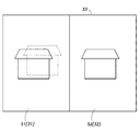
図6は、揺れ画像31および揺れ補正画像32を画面二分割方式で合成した例を示す図である。図6の例では、合成画像33は、左右方向に互いに並んで配置された第1画面51および第2画面52とから構成されている。そして、左側の第1画面51に揺れ画像31が配置され、右側の第2画面52に揺れ補正画像32が配置されるように、揺れ画像31と揺れ補正画像32とを合成している。揺れ画像31および揺れ補正画像32の各画面サイズは、第1画面51および第2画面52の各画面サイズに適合するように縮小させる。
FIG. 6 is a diagram showing an example in which the
また、第1画面51および第2画面52の各画面サイズは、モニタ装置2から入力されるユーザからの命令に基づき変更可能である。図6の例では、第1画面51および第2画面52は互いに同一の画面サイズを有しているが、第1画面51および第2画面52の一方が他方よりも大きいまたは小さい画面サイズを有するように画面サイズを変更してもよい。
Further, the screen sizes of the
また、図6の例では、左側の第1画面51に揺れ画像31が配置され、右側の第2画面52に揺れ補正画像32が配置されるように合成したが、これとは逆に、左側の第1画面51に揺れ補正画像32が配置され、右側の第2画面52に揺れ画像31が配置されるように合成してもよい。
In the example of FIG. 6, the image is synthesized so that the
また、図6の例では、合成画像33を構成する第1画面51および第2画面52は、左右方向に配置されているが、第1画面51および第2画面52は、左右方向ではなく上下方向に配置してもよい。
In the example of FIG. 6, the
(第2実施形態)
図7は、本開示の第2実施形態に係る撮像装置1の概略構成図である。なお、この第2実施形態では、以下で特に言及しない事項については、上述の第1実施形態の場合と同様とする。
(Second Embodiment)
FIG. 7 is a schematic configuration diagram of the
この第2実施形態では、撮像装置1が光学系制御部19をさらに備えており、この光学系制御部19が補正量算出部15で算出された補正量に基づいてイメージセンサ12を水平方向(x方向)および垂直方向(y方向)に変位させることにより画像揺れを補正している。そのため、カメラ信号処理部13で生成されたフレーム画像は、画像揺れが補正された揺れ補正画像となる。したがって、この第2実施形態では、イメージセンサ12は、揺れ補正画像を生成する揺れ補正画像生成部22と見なすことができる。
In the second embodiment, the
この第2実施形態では、画像合成部18は、補正量算出部15で算出された補正量に基づきカメラ信号処理部13から取得した揺れ補正画像に対して幾何学的変換を施すことにより、画像揺れを含む揺れ画像を生成する揺れ画像生成部21と、揺れ画像と揺れ補正画像とを同一画面上に配置した合成画像を生成する合成画像生成部23とを含む。
In the second embodiment, the
図8および図9は、画像合成部18の揺れ画像生成部21および合成画像生成部23での各処理を説明するための図である。
FIGS. 8 and 9 are diagrams for explaining each process in the shake
まず、揺れ画像生成部21は、カメラ信号処理部13から現フレーム(フレームN)のフレーム画像(画像データ)を取得する。上述したように、カメラ信号処理部13で生成されたフレーム画像は、画像揺れが補正された揺れ補正画像32である。また、揺れ画像生成部21は、補正量算出部15から、現フレーム(フレームN)の補正量「Δx(N)、Δy(N)」(図2参照)を取得する。
First, the shaking
続いて、揺れ画像生成部21は、図9に示すように、補正量算出部15から取得した補正量「Δx(N)、Δy(N)」に基づき、現フレーム(フレームN)のフレーム画像である揺れ補正画像32に対して幾何学的変換を施すことにより、画像揺れを含む揺れ画像31を生成する。この揺れ画像31は、画像揺れを補正する前の現フレーム画像に相当する画像と見なされ、合成画像生成部23において、現フレーム画像の代わりに用いられる。
Subsequently, as illustrated in FIG. 9, the shaking
次に、合成画像生成部23は、現フレーム画像の代わりである揺れ画像31と揺れ補正画像32とを、両画像が同一画面上に配置されるように合成した合成画像33を生成する。揺れ画像31および揺れ補正画像32を合成する方式は、上述の第1実施形態と同様であるので説明は省略する。
Next, the composite
以上、本開示を特定の実施形態に基づいて説明したが、これらの実施形態はあくまでも例示であって、本開示はこれらの実施形態によって限定されるものではない。また、上記実施形態に示した本開示に係る撮像装置および撮像画像の表示方法の各構成要素は、必ずしも全てが必須ではなく、少なくとも本開示の範囲を逸脱しない限りにおいて適宜取捨選択することが可能である。 As mentioned above, although this indication was explained based on specific embodiments, these embodiments are illustrations to the last, and this indication is not limited by these embodiments. In addition, all the components of the imaging device and the method for displaying a captured image according to the present disclosure shown in the above embodiment are not necessarily essential, and can be appropriately selected as long as they do not depart from the scope of the present disclosure. It is.
例えば、上記の実施形態では、現フレーム画像の画像揺れを補正するための補正量は、角速度センサにより検出した撮像装置1の揺れ量に基づき算出したが、角速度センサの検出結果ではなく、現フレーム画像とその1つ前のフレーム画像との間での被写体の変位量に基づいて算出するようにしてもよい。
For example, in the above embodiment, the correction amount for correcting the image shake of the current frame image is calculated based on the shake amount of the
本開示に係る撮像装置および撮像画像の表示方法は、撮像画像とその揺れ補正画像とを同一画面上に表示することができる撮像装置および撮像画像の表示方法として有用である。 An imaging apparatus and a captured image display method according to the present disclosure are useful as an imaging apparatus and a captured image display method that can display a captured image and a shake-corrected image on the same screen.
1 撮像装置
2 モニタ装置
3 ネットワーク
11 レンズ系
12 イメージセンサ
13 カメラ信号処理部
14 角速度センサ
15 補正量算出部
16 ネットワークインターフェース(I/F)
17 制御部
18 画像合成部
19 光学系制御部
21 揺れ画像生成部
22 揺れ補正画像生成部
23 合成画像生成部
31 揺れ画像
32 揺れ補正画像
33 合成画像
42 親画面
42 子画面
51 第1画面
52 第2画面
DESCRIPTION OF
DESCRIPTION OF
Claims (7)
該撮像装置の物理的揺れ量を検出する角速度センサと、
前記物理的揺れ量に基づき現フレーム画像の画像揺れを補正するための補正量を算出する補正量算出部と、
前記補正量に基づき前記現フレーム画像に対して幾何学的変換を施すことにより、前記画像揺れが補正された揺れ補正画像を生成する揺れ補正画像生成部と、
前記現フレーム画像と前記揺れ補正画像とを同一画面上に配置した合成画像を生成する合成画像生成部と、
前記補正画像生成部および前記合成画像生成部の各処理を制御する制御部と、を備え、
前記制御部は、前記物理的揺れ量が一定値以上検出された場合に、前記合成画像の生成を行うことを特徴とする撮像装置。 An imaging device that captures a captured image composed of a plurality of frame images in a time series using an imaging element,
An angular velocity sensor for detecting the amount of physical shaking of the imaging device;
A correction amount calculation unit that calculates a correction amount for correcting image shaking of the current frame image based on the physical shaking amount ;
A shake correction image generation unit that generates a shake correction image in which the image shake is corrected by performing geometric transformation on the current frame image based on the correction amount;
And composite image generating unit that generates a composite image positioned above and the shake correction image and the current frame image on the same screen,
A control unit that controls each process of the corrected image generation unit and the composite image generation unit,
The control unit is configured to generate the composite image when the physical shake amount is detected to be a predetermined value or more .
前記合成画像生成部は、前記現フレーム画像および前記揺れ補正画像の一方を前記親画面に配置し、他方を前記子画面に配置することを特徴とする請求項1に記載の撮像装置。 The composite image is composed of a parent screen and a child screen arranged on the parent screen,
The imaging apparatus according to claim 1, wherein the composite image generation unit arranges one of the current frame image and the shake correction image on the parent screen and the other on the child screen.
前記合成画像生成部は、前記現フレーム画像および前記揺れ補正画像の一方を前記第1画面に配置し、他方を前記第2画面に配置することを特徴とする請求項1に記載の撮像装置。 The composite image is composed of a first screen and a second screen arranged side by side in the left-right direction or the vertical direction,
The imaging apparatus according to claim 1, wherein the composite image generation unit arranges one of the current frame image and the shake correction image on the first screen and the other on the second screen.
該撮像装置の物理的揺れ量を検出する角速度センサと、
前記物理的揺れ量に基づき現フレーム画像の画像揺れを補正するための補正量を算出する補正量算出部と、
前記補正量に基づきイメージセンサの光学系を制御して、前記画像揺れが補正された揺れ補正画像を生成する揺れ補正画像生成部と、
前記補正量に基づき前記揺れ補正画像に対して幾何学的変換を施すことにより、前記画像揺れを含む揺れ画像を生成する揺れ画像生成部と、
前記揺れ画像と前記揺れ補正画像とを同一画面上に配置した合成画像を生成する合成画像生成部と、
を備えたことを特徴とする撮像装置。 An imaging device that captures a captured image composed of a plurality of frame images in a time series using an imaging element,
An angular velocity sensor for detecting the amount of physical shaking of the imaging device;
A correction amount calculation unit that calculates a correction amount for correcting image shaking of the current frame image based on the physical shaking amount;
A shake correction image generation unit that controls an optical system of an image sensor based on the correction amount and generates a shake correction image in which the image shake is corrected;
A shake image generation unit that generates a shake image including the image shake by performing geometric transformation on the shake correction image based on the correction amount;
A composite image generation unit that generates a composite image in which the shake image and the shake correction image are arranged on the same screen;
An imaging apparatus comprising:
該撮像装置の物理的揺れ量を検出するステップと、
前記物理的揺れ量に基づき現フレーム画像の画像揺れを補正するための補正量を算出するステップと、
前記補正量に基づき前記現フレーム画像に対して幾何学的変換を施すことにより、前記画像揺れが補正された揺れ補正画像を生成するステップと、
前記現フレーム画像と前記揺れ補正画像とを同一画面上に配置した合成画像を生成するステップと、
前記揺れ補正画像の生成および前記合成画像の生成の各処理を制御するステップと、を有し、
前記制御するステップは、前記物理的揺れ量が一定値以上検出された場合に、前記合成画像の生成を行うことを特徴とする撮像画像の表示方法。 A display method of a captured image composed of a plurality of frame images captured in time series by an image sensor,
Detecting the amount of physical shaking of the imaging device;
Calculating a correction amount for correcting image shake of the current frame image based on the physical shake amount ;
Generating a shake correction image in which the image shake is corrected by performing geometric transformation on the current frame image based on the correction amount; and
Generating a composite image in which the current frame image and the shake correction image are arranged on the same screen;
Controlling each process of generation of the shake correction image and generation of the composite image,
The control step includes generating the composite image when the physical fluctuation amount is detected to be a certain value or more .
Priority Applications (3)
| Application Number | Priority Date | Filing Date | Title |
|---|---|---|---|
| JP2017040423A JP6410062B2 (en) | 2017-03-03 | 2017-03-03 | Imaging device and display method of captured image |
| PCT/JP2018/001495 WO2018159145A1 (en) | 2017-03-03 | 2018-01-19 | Image capturing device and captured image display method |
| US16/489,248 US10986272B2 (en) | 2017-03-03 | 2018-01-19 | Image capturing device and captured image display method |
Applications Claiming Priority (1)
| Application Number | Priority Date | Filing Date | Title |
|---|---|---|---|
| JP2017040423A JP6410062B2 (en) | 2017-03-03 | 2017-03-03 | Imaging device and display method of captured image |
Publications (2)
| Publication Number | Publication Date |
|---|---|
| JP2018148344A JP2018148344A (en) | 2018-09-20 |
| JP6410062B2 true JP6410062B2 (en) | 2018-10-24 |
Family
ID=63371398
Family Applications (1)
| Application Number | Title | Priority Date | Filing Date |
|---|---|---|---|
| JP2017040423A Active JP6410062B2 (en) | 2017-03-03 | 2017-03-03 | Imaging device and display method of captured image |
Country Status (3)
| Country | Link |
|---|---|
| US (1) | US10986272B2 (en) |
| JP (1) | JP6410062B2 (en) |
| WO (1) | WO2018159145A1 (en) |
Families Citing this family (1)
| Publication number | Priority date | Publication date | Assignee | Title |
|---|---|---|---|---|
| JP2022052532A (en) * | 2020-09-23 | 2022-04-04 | キヤノン株式会社 | Image processing apparatus, image capturing apparatus, image capture control device and control method thereof, and program |
Family Cites Families (14)
| Publication number | Priority date | Publication date | Assignee | Title |
|---|---|---|---|---|
| JP4280363B2 (en) | 1999-07-02 | 2009-06-17 | キヤノン株式会社 | Image processing device |
| JP4162333B2 (en) | 1999-07-09 | 2008-10-08 | 株式会社東芝 | Monitoring system |
| JP3697129B2 (en) * | 2000-01-20 | 2005-09-21 | キヤノン株式会社 | Imaging device |
| JP2006100903A (en) | 2004-09-28 | 2006-04-13 | Funai Electric Co Ltd | Video recorder |
| JP4379918B2 (en) | 2004-11-29 | 2009-12-09 | 富士フイルム株式会社 | Imaging apparatus and imaging method |
| JP2006340063A (en) | 2005-06-02 | 2006-12-14 | Canon Inc | Image recording/reproducing apparatus |
| JP2007081685A (en) | 2005-09-13 | 2007-03-29 | Sony Corp | Image signal processor, image signal processing method, and image signal processing system |
| JP2009060154A (en) * | 2005-12-22 | 2009-03-19 | Panasonic Corp | Video content recording method, video content recording apparatus, video content reproducing method, and video content reproducing apparatus |
| KR101488795B1 (en) * | 2008-03-25 | 2015-02-04 | 엘지전자 주식회사 | Mobile terminal and control method thereof |
| JP4742324B2 (en) | 2009-02-17 | 2011-08-10 | カシオ計算機株式会社 | Recording apparatus, recording method, and program for recording moving image |
| JP2010204160A (en) | 2009-02-27 | 2010-09-16 | Panasonic Corp | Image pickup device |
| JP2013066046A (en) * | 2011-09-16 | 2013-04-11 | Hitachi Kokusai Electric Inc | Imaging device |
| JP2015039085A (en) * | 2011-12-14 | 2015-02-26 | パナソニック株式会社 | Image processor and image processing method |
| JP2015095670A (en) * | 2013-11-08 | 2015-05-18 | キヤノン株式会社 | Imaging apparatus, control method thereof and control program |
-
2017
- 2017-03-03 JP JP2017040423A patent/JP6410062B2/en active Active
-
2018
- 2018-01-19 WO PCT/JP2018/001495 patent/WO2018159145A1/en active Application Filing
- 2018-01-19 US US16/489,248 patent/US10986272B2/en active Active
Also Published As
| Publication number | Publication date |
|---|---|
| WO2018159145A1 (en) | 2018-09-07 |
| US20200068130A1 (en) | 2020-02-27 |
| US10986272B2 (en) | 2021-04-20 |
| JP2018148344A (en) | 2018-09-20 |
Similar Documents
| Publication | Publication Date | Title |
|---|---|---|
| JP6587113B2 (en) | Image processing apparatus and image processing method | |
| JP5414405B2 (en) | Image processing apparatus, imaging apparatus, and image processing method | |
| JP4931055B2 (en) | Image processing apparatus and image processing method | |
| JP6525707B2 (en) | Image processing apparatus, control method and program therefor, and imaging apparatus | |
| CN106911889B (en) | Image blur correction apparatus and tilt correction apparatus, and control methods thereof | |
| JP6079031B2 (en) | Imaging device | |
| JP2011029735A5 (en) | ||
| JP6594180B2 (en) | IMAGING DEVICE, IMAGING DEVICE CONTROL METHOD, AND PROGRAM | |
| JP6361931B2 (en) | Image processing apparatus, imaging system including the same, and image processing method | |
| JP6674701B2 (en) | Image processing module and semiconductor system | |
| JP5952782B2 (en) | Image processing apparatus, control method therefor, program, and storage medium | |
| CN110708458B (en) | Image frame compensation method, camera and thermal imaging camera | |
| JP4865587B2 (en) | Stationary imaging device | |
| JP5797003B2 (en) | Imaging apparatus, control method therefor, program, and storage medium | |
| JP2018186514A (en) | Image processing device, imaging system having the same and image processing method | |
| CN110351475B (en) | Image pickup system, information processing apparatus, control method therefor, and storage medium | |
| JP6410062B2 (en) | Imaging device and display method of captured image | |
| JP6421955B2 (en) | Imaging device and method for correcting shake of captured image | |
| WO2019182101A1 (en) | Multi-eye camera system, multi-eye photographing camera head, image processing device, multi-eye photographing program and multi-eye photographing method | |
| JP2009065519A (en) | Image processing apparatus | |
| JP5831492B2 (en) | Imaging apparatus, display control method, and program | |
| JP2009088850A (en) | Moving image distribution system and moving image distributing method | |
| JP2014112796A (en) | Image pick-up device and image pick-up method | |
| US20210409607A1 (en) | Control apparatus, control method, and storage medium | |
| JP4988479B2 (en) | Character information synthesizing apparatus and character information synthesizing method |
Legal Events
| Date | Code | Title | Description |
|---|---|---|---|
| TRDD | Decision of grant or rejection written | ||
| A01 | Written decision to grant a patent or to grant a registration (utility model) |
Free format text: JAPANESE INTERMEDIATE CODE: A01 Effective date: 20180814 |
|
| A61 | First payment of annual fees (during grant procedure) |
Free format text: JAPANESE INTERMEDIATE CODE: A61 Effective date: 20180911 |
|
| R151 | Written notification of patent or utility model registration |
Ref document number: 6410062 Country of ref document: JP Free format text: JAPANESE INTERMEDIATE CODE: R151 |