JP6397018B2 - Medical viewing system with viewing angle optimization function - Google Patents
Medical viewing system with viewing angle optimization function Download PDFInfo
- Publication number
- JP6397018B2 JP6397018B2 JP2016530863A JP2016530863A JP6397018B2 JP 6397018 B2 JP6397018 B2 JP 6397018B2 JP 2016530863 A JP2016530863 A JP 2016530863A JP 2016530863 A JP2016530863 A JP 2016530863A JP 6397018 B2 JP6397018 B2 JP 6397018B2
- Authority
- JP
- Japan
- Prior art keywords
- ray
- processing unit
- live
- markers
- ray image
- Prior art date
- Legal status (The legal status is an assumption and is not a legal conclusion. Google has not performed a legal analysis and makes no representation as to the accuracy of the status listed.)
- Active
Links
- 238000005457 optimization Methods 0.000 title 1
- 238000000034 method Methods 0.000 claims description 47
- 239000000523 sample Substances 0.000 claims description 20
- 238000002604 ultrasonography Methods 0.000 claims description 16
- 238000004590 computer program Methods 0.000 claims description 14
- 210000000056 organ Anatomy 0.000 claims description 14
- 238000002592 echocardiography Methods 0.000 claims description 10
- 239000000284 extract Substances 0.000 claims description 3
- 239000003550 marker Substances 0.000 description 32
- 238000003384 imaging method Methods 0.000 description 18
- 210000001765 aortic valve Anatomy 0.000 description 13
- 210000000709 aorta Anatomy 0.000 description 9
- 239000002872 contrast media Substances 0.000 description 9
- 238000001514 detection method Methods 0.000 description 5
- 230000033001 locomotion Effects 0.000 description 4
- 238000002583 angiography Methods 0.000 description 3
- 238000004422 calculation algorithm Methods 0.000 description 3
- 238000004364 calculation method Methods 0.000 description 3
- 238000002594 fluoroscopy Methods 0.000 description 3
- 230000006870 function Effects 0.000 description 3
- 210000003709 heart valve Anatomy 0.000 description 3
- 238000002584 aortography Methods 0.000 description 2
- 210000004204 blood vessel Anatomy 0.000 description 2
- 230000001419 dependent effect Effects 0.000 description 2
- 238000010586 diagram Methods 0.000 description 2
- 230000004927 fusion Effects 0.000 description 2
- 238000010845 search algorithm Methods 0.000 description 2
- 238000013175 transesophageal echocardiography Methods 0.000 description 2
- 230000003936 working memory Effects 0.000 description 2
- 210000005242 cardiac chamber Anatomy 0.000 description 1
- 230000000747 cardiac effect Effects 0.000 description 1
- 210000003238 esophagus Anatomy 0.000 description 1
- 208000019622 heart disease Diseases 0.000 description 1
- 210000005003 heart tissue Anatomy 0.000 description 1
- 230000004807 localization Effects 0.000 description 1
- 230000015654 memory Effects 0.000 description 1
- 210000004115 mitral valve Anatomy 0.000 description 1
- 230000003287 optical effect Effects 0.000 description 1
- 238000002360 preparation method Methods 0.000 description 1
- 230000005855 radiation Effects 0.000 description 1
- 239000004065 semiconductor Substances 0.000 description 1
- 210000004872 soft tissue Anatomy 0.000 description 1
- 238000011272 standard treatment Methods 0.000 description 1
- 238000011282 treatment Methods 0.000 description 1
- 230000000007 visual effect Effects 0.000 description 1
Images


Classifications
-
- A—HUMAN NECESSITIES
- A61—MEDICAL OR VETERINARY SCIENCE; HYGIENE
- A61B—DIAGNOSIS; SURGERY; IDENTIFICATION
- A61B6/00—Apparatus or devices for radiation diagnosis; Apparatus or devices for radiation diagnosis combined with radiation therapy equipment
- A61B6/52—Devices using data or image processing specially adapted for radiation diagnosis
- A61B6/5211—Devices using data or image processing specially adapted for radiation diagnosis involving processing of medical diagnostic data
- A61B6/5229—Devices using data or image processing specially adapted for radiation diagnosis involving processing of medical diagnostic data combining image data of a patient, e.g. combining a functional image with an anatomical image
- A61B6/5247—Devices using data or image processing specially adapted for radiation diagnosis involving processing of medical diagnostic data combining image data of a patient, e.g. combining a functional image with an anatomical image combining images from an ionising-radiation diagnostic technique and a non-ionising radiation diagnostic technique, e.g. X-ray and ultrasound
-
- A—HUMAN NECESSITIES
- A61—MEDICAL OR VETERINARY SCIENCE; HYGIENE
- A61B—DIAGNOSIS; SURGERY; IDENTIFICATION
- A61B34/00—Computer-aided surgery; Manipulators or robots specially adapted for use in surgery
- A61B34/25—User interfaces for surgical systems
-
- A—HUMAN NECESSITIES
- A61—MEDICAL OR VETERINARY SCIENCE; HYGIENE
- A61B—DIAGNOSIS; SURGERY; IDENTIFICATION
- A61B6/00—Apparatus or devices for radiation diagnosis; Apparatus or devices for radiation diagnosis combined with radiation therapy equipment
- A61B6/12—Arrangements for detecting or locating foreign bodies
-
- A—HUMAN NECESSITIES
- A61—MEDICAL OR VETERINARY SCIENCE; HYGIENE
- A61B—DIAGNOSIS; SURGERY; IDENTIFICATION
- A61B6/00—Apparatus or devices for radiation diagnosis; Apparatus or devices for radiation diagnosis combined with radiation therapy equipment
- A61B6/46—Arrangements for interfacing with the operator or the patient
- A61B6/461—Displaying means of special interest
- A61B6/463—Displaying means of special interest characterised by displaying multiple images or images and diagnostic data on one display
-
- A—HUMAN NECESSITIES
- A61—MEDICAL OR VETERINARY SCIENCE; HYGIENE
- A61B—DIAGNOSIS; SURGERY; IDENTIFICATION
- A61B6/00—Apparatus or devices for radiation diagnosis; Apparatus or devices for radiation diagnosis combined with radiation therapy equipment
- A61B6/46—Arrangements for interfacing with the operator or the patient
- A61B6/467—Arrangements for interfacing with the operator or the patient characterised by special input means
-
- A—HUMAN NECESSITIES
- A61—MEDICAL OR VETERINARY SCIENCE; HYGIENE
- A61B—DIAGNOSIS; SURGERY; IDENTIFICATION
- A61B6/00—Apparatus or devices for radiation diagnosis; Apparatus or devices for radiation diagnosis combined with radiation therapy equipment
- A61B6/48—Diagnostic techniques
- A61B6/486—Diagnostic techniques involving generating temporal series of image data
- A61B6/487—Diagnostic techniques involving generating temporal series of image data involving fluoroscopy
-
- A—HUMAN NECESSITIES
- A61—MEDICAL OR VETERINARY SCIENCE; HYGIENE
- A61B—DIAGNOSIS; SURGERY; IDENTIFICATION
- A61B6/00—Apparatus or devices for radiation diagnosis; Apparatus or devices for radiation diagnosis combined with radiation therapy equipment
- A61B6/50—Apparatus or devices for radiation diagnosis; Apparatus or devices for radiation diagnosis combined with radiation therapy equipment specially adapted for specific body parts; specially adapted for specific clinical applications
- A61B6/503—Apparatus or devices for radiation diagnosis; Apparatus or devices for radiation diagnosis combined with radiation therapy equipment specially adapted for specific body parts; specially adapted for specific clinical applications for diagnosis of the heart
-
- A—HUMAN NECESSITIES
- A61—MEDICAL OR VETERINARY SCIENCE; HYGIENE
- A61B—DIAGNOSIS; SURGERY; IDENTIFICATION
- A61B8/00—Diagnosis using ultrasonic, sonic or infrasonic waves
- A61B8/08—Detecting organic movements or changes, e.g. tumours, cysts, swellings
- A61B8/0883—Detecting organic movements or changes, e.g. tumours, cysts, swellings for diagnosis of the heart
-
- A—HUMAN NECESSITIES
- A61—MEDICAL OR VETERINARY SCIENCE; HYGIENE
- A61B—DIAGNOSIS; SURGERY; IDENTIFICATION
- A61B8/00—Diagnosis using ultrasonic, sonic or infrasonic waves
- A61B8/12—Diagnosis using ultrasonic, sonic or infrasonic waves in body cavities or body tracts, e.g. by using catheters
-
- A—HUMAN NECESSITIES
- A61—MEDICAL OR VETERINARY SCIENCE; HYGIENE
- A61B—DIAGNOSIS; SURGERY; IDENTIFICATION
- A61B8/00—Diagnosis using ultrasonic, sonic or infrasonic waves
- A61B8/46—Ultrasonic, sonic or infrasonic diagnostic devices with special arrangements for interfacing with the operator or the patient
- A61B8/461—Displaying means of special interest
- A61B8/463—Displaying means of special interest characterised by displaying multiple images or images and diagnostic data on one display
-
- A—HUMAN NECESSITIES
- A61—MEDICAL OR VETERINARY SCIENCE; HYGIENE
- A61B—DIAGNOSIS; SURGERY; IDENTIFICATION
- A61B8/00—Diagnosis using ultrasonic, sonic or infrasonic waves
- A61B8/46—Ultrasonic, sonic or infrasonic diagnostic devices with special arrangements for interfacing with the operator or the patient
- A61B8/467—Ultrasonic, sonic or infrasonic diagnostic devices with special arrangements for interfacing with the operator or the patient characterised by special input means
-
- A—HUMAN NECESSITIES
- A61—MEDICAL OR VETERINARY SCIENCE; HYGIENE
- A61B—DIAGNOSIS; SURGERY; IDENTIFICATION
- A61B8/00—Diagnosis using ultrasonic, sonic or infrasonic waves
- A61B8/52—Devices using data or image processing specially adapted for diagnosis using ultrasonic, sonic or infrasonic waves
- A61B8/5215—Devices using data or image processing specially adapted for diagnosis using ultrasonic, sonic or infrasonic waves involving processing of medical diagnostic data
- A61B8/5238—Devices using data or image processing specially adapted for diagnosis using ultrasonic, sonic or infrasonic waves involving processing of medical diagnostic data for combining image data of patient, e.g. merging several images from different acquisition modes into one image
- A61B8/5261—Devices using data or image processing specially adapted for diagnosis using ultrasonic, sonic or infrasonic waves involving processing of medical diagnostic data for combining image data of patient, e.g. merging several images from different acquisition modes into one image combining images from different diagnostic modalities, e.g. ultrasound and X-ray
-
- A—HUMAN NECESSITIES
- A61—MEDICAL OR VETERINARY SCIENCE; HYGIENE
- A61B—DIAGNOSIS; SURGERY; IDENTIFICATION
- A61B90/00—Instruments, implements or accessories specially adapted for surgery or diagnosis and not covered by any of the groups A61B1/00 - A61B50/00, e.g. for luxation treatment or for protecting wound edges
- A61B90/36—Image-producing devices or illumination devices not otherwise provided for
- A61B90/37—Surgical systems with images on a monitor during operation
-
- G—PHYSICS
- G06—COMPUTING; CALCULATING OR COUNTING
- G06T—IMAGE DATA PROCESSING OR GENERATION, IN GENERAL
- G06T7/00—Image analysis
- G06T7/0002—Inspection of images, e.g. flaw detection
- G06T7/0012—Biomedical image inspection
-
- A—HUMAN NECESSITIES
- A61—MEDICAL OR VETERINARY SCIENCE; HYGIENE
- A61B—DIAGNOSIS; SURGERY; IDENTIFICATION
- A61B17/00—Surgical instruments, devices or methods, e.g. tourniquets
- A61B2017/00743—Type of operation; Specification of treatment sites
- A61B2017/00778—Operations on blood vessels
- A61B2017/00783—Valvuloplasty
-
- A—HUMAN NECESSITIES
- A61—MEDICAL OR VETERINARY SCIENCE; HYGIENE
- A61B—DIAGNOSIS; SURGERY; IDENTIFICATION
- A61B90/00—Instruments, implements or accessories specially adapted for surgery or diagnosis and not covered by any of the groups A61B1/00 - A61B50/00, e.g. for luxation treatment or for protecting wound edges
- A61B90/36—Image-producing devices or illumination devices not otherwise provided for
- A61B2090/364—Correlation of different images or relation of image positions in respect to the body
-
- A—HUMAN NECESSITIES
- A61—MEDICAL OR VETERINARY SCIENCE; HYGIENE
- A61B—DIAGNOSIS; SURGERY; IDENTIFICATION
- A61B90/00—Instruments, implements or accessories specially adapted for surgery or diagnosis and not covered by any of the groups A61B1/00 - A61B50/00, e.g. for luxation treatment or for protecting wound edges
- A61B90/36—Image-producing devices or illumination devices not otherwise provided for
- A61B90/37—Surgical systems with images on a monitor during operation
- A61B2090/376—Surgical systems with images on a monitor during operation using X-rays, e.g. fluoroscopy
-
- A—HUMAN NECESSITIES
- A61—MEDICAL OR VETERINARY SCIENCE; HYGIENE
- A61B—DIAGNOSIS; SURGERY; IDENTIFICATION
- A61B90/00—Instruments, implements or accessories specially adapted for surgery or diagnosis and not covered by any of the groups A61B1/00 - A61B50/00, e.g. for luxation treatment or for protecting wound edges
- A61B90/36—Image-producing devices or illumination devices not otherwise provided for
- A61B90/37—Surgical systems with images on a monitor during operation
- A61B2090/378—Surgical systems with images on a monitor during operation using ultrasound
- A61B2090/3782—Surgical systems with images on a monitor during operation using ultrasound transmitter or receiver in catheter or minimal invasive instrument
- A61B2090/3784—Surgical systems with images on a monitor during operation using ultrasound transmitter or receiver in catheter or minimal invasive instrument both receiver and transmitter being in the instrument or receiver being also transmitter
-
- A—HUMAN NECESSITIES
- A61—MEDICAL OR VETERINARY SCIENCE; HYGIENE
- A61B—DIAGNOSIS; SURGERY; IDENTIFICATION
- A61B6/00—Apparatus or devices for radiation diagnosis; Apparatus or devices for radiation diagnosis combined with radiation therapy equipment
- A61B6/44—Constructional features of apparatus for radiation diagnosis
- A61B6/4429—Constructional features of apparatus for radiation diagnosis related to the mounting of source units and detector units
- A61B6/4435—Constructional features of apparatus for radiation diagnosis related to the mounting of source units and detector units the source unit and the detector unit being coupled by a rigid structure
- A61B6/4441—Constructional features of apparatus for radiation diagnosis related to the mounting of source units and detector units the source unit and the detector unit being coupled by a rigid structure the rigid structure being a C-arm or U-arm
-
- A—HUMAN NECESSITIES
- A61—MEDICAL OR VETERINARY SCIENCE; HYGIENE
- A61B—DIAGNOSIS; SURGERY; IDENTIFICATION
- A61B8/00—Diagnosis using ultrasonic, sonic or infrasonic waves
- A61B8/13—Tomography
- A61B8/14—Echo-tomography
Landscapes
- Health & Medical Sciences (AREA)
- Life Sciences & Earth Sciences (AREA)
- Engineering & Computer Science (AREA)
- Medical Informatics (AREA)
- Surgery (AREA)
- Nuclear Medicine, Radiotherapy & Molecular Imaging (AREA)
- General Health & Medical Sciences (AREA)
- Veterinary Medicine (AREA)
- Public Health (AREA)
- Animal Behavior & Ethology (AREA)
- Molecular Biology (AREA)
- Biomedical Technology (AREA)
- Heart & Thoracic Surgery (AREA)
- Radiology & Medical Imaging (AREA)
- Pathology (AREA)
- Physics & Mathematics (AREA)
- Biophysics (AREA)
- Optics & Photonics (AREA)
- High Energy & Nuclear Physics (AREA)
- Computer Vision & Pattern Recognition (AREA)
- Human Computer Interaction (AREA)
- Cardiology (AREA)
- Oral & Maxillofacial Surgery (AREA)
- Dentistry (AREA)
- Gynecology & Obstetrics (AREA)
- Robotics (AREA)
- Quality & Reliability (AREA)
- General Physics & Mathematics (AREA)
- Theoretical Computer Science (AREA)
- Ultra Sonic Daignosis Equipment (AREA)
- Apparatus For Radiation Diagnosis (AREA)
Description
本発明は、医療ビューイングシステム、医療画像を提供する方法、コンピュータプログラム及びコンピュータ可読媒体に関する。 The present invention relates to a medical viewing system, a method for providing medical images, a computer program, and a computer readable medium.
二次元X線撮像は、心臓インターベンションに対する有力な撮像モダリティである。軟組織情報を要求する処置、例えば、器質的心疾患のガイダンスを提供するために、心エコー情報も採用される。例えば、経カテーテル大動脈弁置換処置(TAVR)は、ライブX線(蛍光透視法)及びライブ超音波(心エコー)撮像の両方に依存するインターベンション心臓病学における挑戦的な処置である。安全に大動脈弁の人工弁置換術を展開するために、X線画像取得装置、例えばCアーム撮像装置の位置に対する最適な視野角(viewing angle)が、要求される。人工弁を展開するのに最適な視野角は、自然(又は元の)大動脈弁の3つ全ての弁尖の下部(底、nadirs)が前記X線画像において可視であるX線視野角である。尖底は、互いに整列し、前記最適な視野角において前記X線画像において等間隔で離れているべきである。 Two-dimensional X-ray imaging is a powerful imaging modality for cardiac intervention. Echocardiographic information is also employed to provide guidance for procedures requiring soft tissue information, such as organic heart disease. For example, transcatheter aortic valve replacement procedure (TAVR) is a challenging procedure in interventional cardiology that relies on both live x-ray (fluoroscopy) and live ultrasound (echocardiography) imaging. In order to safely deploy the prosthetic valve replacement of the aortic valve, an optimal viewing angle with respect to the position of the X-ray image acquisition device, for example, the C-arm imaging device is required. The optimal viewing angle for deploying the prosthetic valve is the x-ray viewing angle at which the bottom (bottom, nadirs) of all three leaflets of the natural (or original) aortic valve is visible in the x-ray image. . The apex should be aligned with each other and equally spaced in the x-ray image at the optimal viewing angle.
心臓専門医がライブX線画像及びライブ心エコー(経食道心エコー検査、TEE)画像を一緒に融合することによりTAVR処置中に最適なCアーム視野角を迅速に見つけるのを助ける可能性がある画像ガイダンスシステムが、存在する。前記弁尖のTEE画像上に手動で配置されたマーカは、前記X線画像上の近似の弁尖位置に自動的に表示する。 Images that may help cardiologists quickly find the optimal C-arm viewing angle during a TAVR procedure by fusing live X-ray images and live echocardiograms (transesophageal echocardiography, TEE) images together There is a guidance system. The marker manually placed on the TEE image of the leaflet is automatically displayed at the approximate leaflet position on the X-ray image.
しかしながら、前記X線画像内の尖底に対する前記マーカのアライメント(alignment)は、このアプローチが使用される場合、改良に対する対象でありうる。前記底は、上述のTEE画像において配置するのが難しい。 However, the alignment of the marker with respect to the cusp in the X-ray image can be a subject for improvement when this approach is used. The bottom is difficult to place in the TEE image described above.
結果的に、本発明の目的は、弁展開に対する最適な視野角を決めるのに有用であるように、前記X線画像内の尖底に対するマーカのアライメントが改良されると同時に、ライブ蛍光透視画像及び心エコー画像を融合することができる撮像システムを提供することである。 As a result, the object of the present invention is to improve the alignment of the marker with respect to the cusp in the X-ray image so that it is useful for determining the optimal viewing angle for valve deployment, while at the same time providing a live fluoroscopic image. And an imaging system capable of fusing echocardiographic images.
前記目的は、独立請求項1のフィーチャを持つシステムにより満たされる。有利な実施例及び更なる改良は、下位請求項及び以下の記載から集められうる。 Said object is met by a system having the features of independent claim 1. Advantageous embodiments and further improvements can be gathered from the subclaims and the following description.
可変視野角からライブX線画像を提供するX線画像取得装置と、ライブ超音波画像を提供する超音波プローブを持つ心エコー撮像装置と、前記X線画像取得装置及び前記心エコー撮像装置に接続可能な処理ユニットとを有する医療ビューイングシステムが、提案される。前記医療ビューイングシステムは、2つの異なる視野角において前記超音波プローブのX線蛍光透視画像の第1のセットを取得するように構成される。前記処理ユニットは、
‐前記X線蛍光透視画像の第1のセットに基づいてライブ超音波及びライブX線画像を位置合わせし、
‐後のフレームにおいて特徴的フィーチャのセットの位置を特定し、
‐前記特徴的フィーチャの認識された位置にマッチするようにマーカのセットを確立し、
‐前記X線画像取得装置の最適な視野角を決定し、前記最適な視野角において前記マーカがX線視野において所定の関係を持つ、
ように構成される。
Connected to an X-ray image acquisition device that provides a live X-ray image from a variable viewing angle, an echocardiography device having an ultrasound probe that provides a live ultrasound image, and the X-ray image acquisition device and the echocardiography device A medical viewing system with a possible processing unit is proposed. The medical viewing system is configured to acquire a first set of x-ray fluoroscopic images of the ultrasound probe at two different viewing angles. The processing unit is
-Aligning live ultrasound and live X-ray images based on the first set of X-ray fluoroscopic images;
-Locate the feature set in later frames,
-Establishing a set of markers to match the recognized positions of the characteristic features;
-Determining an optimum viewing angle of the X-ray image acquisition device, wherein the marker has a predetermined relationship in the X-ray field at the optimum viewing angle;
Configured as follows.
前記X線画像取得装置は、好ましくは、X線源及び前記X線源の真向かいに取り付けられたX線検出器を持つCアーム構造、並びに前記Cアーム構造の回転移動に対するモータ付駆動装置を含むCアームアセンブリを有してもよい。前記Cアーム構造は、回転軸の周りで及び可変視野角で複数のX線投影を取得するアイソセンタの周りで回転スキャンを実行するように備えられる。前記X線画像取得装置に接続された前記処理ユニットは、前記Cアーム構造の運動及びX線画像の取得を制御することができる。 The X-ray image acquisition device preferably includes an X-ray source, a C-arm structure having an X-ray detector mounted directly opposite the X-ray source, and a motor-driven drive device for rotational movement of the C-arm structure. You may have a C-arm assembly. The C-arm structure is provided to perform a rotational scan around the rotational axis and around an isocenter that acquires multiple x-ray projections with variable viewing angles. The processing unit connected to the X-ray image acquisition device can control the movement of the C-arm structure and acquisition of X-ray images.
前記心エコー撮像装置は、先端に超音波トランスデューサを含むプローブを持つ撮像装置として理解されるべきであり、前記プローブは、ライブ超音波画像及びドップラ評価を提供するために患者の体内に注入されうる又は体上に配置されうる。前記プローブは、患者の食道内に挿入されるべき経食道心エコー(TEE)プローブ、又は前記患者の胸部上にはいちされるべき経胸壁心エコー(TTE)プローブのような、様々な異なるプローブから選択されうる。特に、TEEは、心臓専門医に心臓組織のリアルタイム三次元撮像を提供する。 The echocardiographic device should be understood as an imaging device with a probe that includes an ultrasound transducer at the tip, which can be injected into the patient's body to provide live ultrasound images and Doppler assessments. Or it can be placed on the body. The probe may be a variety of different probes, such as a transesophageal echocardiogram (TEE) probe to be inserted into the patient's esophagus or a transthoracic echocardiogram (TTE) probe to be placed on the patient's chest. Can be selected. In particular, TEE provides cardiologists with real-time three-dimensional imaging of heart tissue.
前記処理ユニットは、プロセッサと、メモリと、ユーザ入力及び前記X線画像取得装置及び前記心エコー撮像装置からのライブ画像データを受信し、データ及び制御信号を出力するインタフェースとを持つ計算ユニットとして理解されるべきである。更に、前記処理ユニットは、上述の機能を実行する複数のアルゴリズムを実行するように構成される。 The processing unit is understood as a calculation unit having a processor, a memory, an interface for receiving user input and live image data from the X-ray image acquisition device and the echocardiography device and outputting data and control signals. It should be. Further, the processing unit is configured to execute a plurality of algorithms that perform the functions described above.
X線画像データ及び心エコーデータの合理的な融合を可能にする基本的な準備機能は、2つの異なる視野角における前記心エコープローブのX線蛍光透視画像の第1のセットを提供することにある。これは、更なる追跡装置を採用する必要なしに画像ベースの心エコープローブ位置特定を行うことを可能にする。 The basic preparatory function that allows the rational fusion of X-ray image data and echocardiographic data is to provide a first set of X-ray fluoroscopic images of the echocardiogram probe at two different viewing angles. is there. This makes it possible to perform image-based echocardiography localization without having to employ additional tracking devices.
前記プローブ位置特定を行った後に、三次元心エコー画像及び二次元蛍光透視画像の正確なリアルタイム位置合わせが、可能である。これは、周知の位置合わせ技術のいずれによって行われてもよく、保護範囲を限定すべきでない。 After performing the probe location, accurate real-time registration of the 3D echocardiogram and the 2D fluoroscopic image is possible. This may be done by any of the known alignment techniques and should not limit the protection range.
前記処理ユニットは、更に、大動脈弁の尖底のような、検査されるべき体/器官の特徴的フィーチャのセットの位置を特定することができる。これは、自動又は半自動でありうる異なる処理によって達成されうる。例えば、前記処理ユニットは、インターベンション医により入力されうる又は前記処理ユニットにより推定されうるマーカ位置の予備セットを受信するように構成される。このマーカ位置の予備セットは、特に、三次元心エコー画像において作成されてもよい。しかしながら、これらは、前記ライブ二次元X線画像において設定されてもよい。これに対する代替例として、三次元画像データも、前記マーカのセットを確立するように前記画像モダリティの1つから使用されてもよい。 The processing unit can further identify the location of a set of body / organ characteristic features to be examined, such as the base of the aortic valve. This can be achieved by different processes that can be automatic or semi-automatic. For example, the processing unit is configured to receive a preliminary set of marker positions that can be input by an interventionist or estimated by the processing unit. This preliminary set of marker positions may in particular be created in a 3D echocardiogram. However, these may be set in the live two-dimensional X-ray image. As an alternative to this, 3D image data may also be used from one of the image modalities to establish the set of markers.
一度前記特徴的フィーチャのセットの位置の座標が特定されると、これらの位置の座標は、マーカ位置に自動的に割り当てられる。この割り当ては、直接的であり、例えば無冠尖及び左冠尖が、それぞれ、大動脈造影(aortogram)画像の探索エリアの左下領域及び右上領域に配置される。同時に、前記ライブ心エコー画像がライブ大動脈造影画像と同時に前記処理ユニットに送信され、位置合わせされるので、前記マーカ位置は、同様に前記心エコー画像上で自動的に調節される。 Once the coordinates of the positions of the set of characteristic features are identified, the coordinates of these positions are automatically assigned to marker positions. This assignment is straightforward, for example, the non-coronal apex and the left coronal apex are located in the lower left and upper right regions of the search area of the aortogram image, respectively. At the same time, the marker position is automatically adjusted on the echocardiogram as well, since the live echocardiogram is sent to the processing unit and registered simultaneously with the live aortic angiogram.
一度前記マーカが、前記特定された位置に配置されると、前記処理ユニットは、容易に前記X線画像取得装置の視野角を調節することができる。これは、前記マーカ(のセット)が所定の関係を有する場合に、前記X線画像取得装置が最適な視野角まで迅速に回転するように制御されることを意味する。特に、TAVR処置に対して、これらは、X線視野において単一の線上にあり、互いから等間隔である。他の処置に対して、他の関係が可能でありうる。 Once the marker is placed at the specified position, the processing unit can easily adjust the viewing angle of the X-ray image acquisition device. This means that when the marker (set) has a predetermined relationship, the X-ray image acquisition device is controlled to rotate rapidly to an optimal viewing angle. In particular, for TAVR procedures, they are on a single line in the x-ray field and are equally spaced from each other. Other relationships may be possible for other treatments.
したがって、前記医療ビューイングシステムは、前記マーカが尖底に配置されるので、最適な視野角に対するX線ビューイング装置の正確な位置決めを提供する。この技術は、特に前記最適な視野角を決定するのにこの医療ビューイングシステムを使用する場合にTAVR処置に対する臨床ワークフローを明確に単純化及び改良する。 Thus, the medical viewing system provides an accurate positioning of the X-ray viewing device for an optimal viewing angle since the marker is placed at the base of the apex. This technique clearly simplifies and improves the clinical workflow for TAVR procedures, especially when using this medical viewing system to determine the optimal viewing angle.
前記処置が開始する前に前記最適な視野角が何であるかの事前指示なしで、複数の大動脈造影が、この角度を決定するのに要求される。例えば、ライブ心エコー画像内の前記弁尖上にマーカを配置することにより、大動脈造影内の弁尖底に前記マーカをアラインする自動補正が、これらのいくつかの代わりに前記最適な視野角を見つけるのに単一の大動脈造影のみを要求する。 Multiple aortics are required to determine this angle without prior indication of what the optimal viewing angle is before the procedure begins. For example, by placing a marker on the leaflet in a live echocardiogram, automatic correction to align the marker to the leaflet bottom in an aortic angiogram will result in the optimal viewing angle instead of some of these. Require only a single aorta to find.
したがって、本発明による撮像システムは、理想的な角度が見つけられるまでの患者に対する放射線量及び造影剤使用の両方を減少させる大きな可能性を持つ。 Thus, the imaging system according to the present invention has great potential to reduce both radiation dose and contrast agent usage to the patient until the ideal angle is found.
この医療ビューイングシステムにより達成可能な前記方法は、他の心臓弁、例えば、僧房弁の置換に対して適用されることもあり得る。 The method achievable with this medical viewing system may be applied to the replacement of other heart valves, for example mitral valves.
前記医療ビューイングシステムが、前記決定された最適な視野角まで前記X線画像取得装置を移動するように構成されることは、好適である。 It is preferred that the medical viewing system is configured to move the X-ray image acquisition device to the determined optimal viewing angle.
有利な実施例において、前記特徴的フィーチャのセットの位置を特定することは、オペレータにより与えられたマーカの予備セットの周りの心エコー画像又はX線画像、すなわち大動脈造影における前記特徴的フィーチャのセットの位置を認識することを有し、前記処理ユニットは、前記認識された位置によって前記マーカの予備セットを調節するように更に構成される。 In an advantageous embodiment, locating the set of characteristic features is an echocardiogram or X-ray image around a pre-set of markers provided by an operator, i.e. the set of characteristic features in aortaography. And the processing unit is further configured to adjust the preliminary set of markers according to the recognized position.
このマーカの予備セットのマーカ位置の精度を改良するために、典型的には、固定の視野角におけるX線大動脈造影が、取得される。これに関連して、大動脈造影は、特に、前記X線画像取得装置により取られた心臓弁の画像のシーケンスを有する。心臓弁及びその周囲の十分な不透明性及びより良好な改良された視覚的検出可能性を提供するために、これらの画像は、造影剤(CA)が血管又は心腔に注入された後に取得される。前記大動脈造影が、注入された造影剤の下で1つの画像のみを有してもよいことは、言うまでもない。また、表現「大動脈造影」の代わりに、表現「弁造影(valvogram)」も、この処理を記述するのに適していてもよい。 In order to improve the accuracy of the marker position of this pre-set of markers, an x-ray aorta image is typically acquired at a fixed viewing angle. In this context, aortic imaging has in particular a sequence of images of heart valves taken by the X-ray image acquisition device. In order to provide sufficient opacity and better improved visual detectability of the heart valve and its surroundings, these images are acquired after contrast agent (CA) has been injected into the blood vessel or heart chamber. The It goes without saying that the aorta contrast may have only one image under the injected contrast agent. Also, instead of the expression “aortography”, the expression “valvogram” may also be suitable for describing this process.
前記大動脈造影画像は、前記大動脈造影画像シーケンスにおける特に前記弁尖底に対する自動探索を行うことを可能にする。点又はフィーチャ検出探索アルゴリズムは、前記大動脈造影画像シーケンスの後のフレームが前記処理ユニットにより受信及び表示されると当該フレームにおいて尖底を位置特定しようと試みてもよい。尖底は、弁尖湾曲が方向を変える前記弁尖上の場所であるので、これは、前記探索を単純化しうる。 The aortic angiographic image makes it possible to perform an automatic search in the aortic angiographic image sequence, in particular for the valve leaflet bottom. A point or feature detection search algorithm may attempt to locate the leaflet in a frame after the aortic contrast image sequence is received and displayed by the processing unit. This can simplify the search because the leaflet is the location on the leaflet where the leaflet curvature changes direction.
したがって、前記医療ビューイングシステムは、特に自然大動脈弁尖の底を位置特定するようにライブ又は保存された大動脈造影画像シーケンスの1以上の画像フレーム上で点又はフィーチャ検出探索を実行することにより正確な補正を提供する。前記マーカは、この場合、前記大動脈造影内の弁尖底まで自動的に移動及びアラインされる。前記ライブX線及びライブ心エコー画像は、同時に前記処理ユニットに転送され、位置合わせされるので、前記マーカ位置は、前記大動脈造影において更新された後に前記心エコー画像において自動的に補正及び更新される。 Thus, the medical viewing system is particularly accurate by performing a point or feature detection search on one or more image frames of an aortic angiographic image sequence that is live or stored to locate the bottom of a natural aortic leaflet. Correct correction. The marker is in this case automatically moved and aligned to the valve leaflet in the aorta. The live X-ray and live echocardiogram are simultaneously transferred to the processing unit and aligned so that the marker position is automatically corrected and updated in the echocardiogram after being updated in the aorta. The
換言すると、本発明による医療ビューイングシステムは、人工弁位置決め及び展開の前の標準的治療の一部として既に得られているX線大動脈造影画像シーケンスに含まれる情報を使用する補正技術を提供する。弁尖底は、前記心エコー画像より前記大動脈造影において容易に検出されることができる。この技術は、前記大動脈造影画像シーケンス内のフィーチャ情報に基づいて弁尖底まで前記マーカを自動的に移動するのにアルゴリズムを使用する。 In other words, the medical viewing system according to the present invention provides a correction technique that uses information contained in X-ray aortic angiographic image sequences already obtained as part of standard treatment prior to prosthetic valve positioning and deployment. . The leaflet bottom can be easily detected in the aortic angiography from the echocardiogram. This technique uses an algorithm to automatically move the marker to the leaflet base based on feature information in the aortic contrast image sequence.
他の典型的な実施例において、前記処理ユニットは、前記X線画像シーケンスの中心領域において前記特徴的フィーチャのセットの位置を認識するように構成される。前記処理ユニットは、前記X線画像シーケンスの中心領域、特に前記X線画像シーケンスの第1のフレーム上の右冠尖のマーカ位置を中心とする領域において尖底を認識するように構成されてもよい。前記マーカを認識する前記アルゴリズムに対して要求される労力は、これにより、明らかに減少されることができる。 In another exemplary embodiment, the processing unit is configured to recognize the position of the feature set in the central region of the x-ray image sequence. The processing unit may be configured to recognize a cusp in a central region of the X-ray image sequence, particularly a region centered on a marker position of a right coronal cusp on a first frame of the X-ray image sequence. Good. The effort required for the algorithm to recognize the marker can thereby be clearly reduced.
更に他の実施例において、前記処理ユニットは、前記心エコー画像に基づいて前記マーカのセットの運動を繰り返し追跡するように構成される。例えば、前記マーカのセットが確立された後に、大動脈基部が移動するときに、前記マーカが前記底に留まることを保証することは、明らかに有利である。更に、前記X線画像取得装置の視野角は、繰り返し再調整されてもよい。両方の撮像モダリティが、前記マーカ位置を追跡するのに使用されてもよいが、特に尖底の場所を示すように前記X線画像内に造影剤がもはや存在しない場合にマーカ運動追跡が可能ではないので、これは、前記心エコー画像に基づいて行う方がおそらく単純である。 In yet another embodiment, the processing unit is configured to repeatedly track the movement of the set of markers based on the echocardiogram. For example, it is clearly advantageous to ensure that the marker stays at the bottom when the aortic base moves after the set of markers is established. Furthermore, the viewing angle of the X-ray image acquisition apparatus may be readjusted repeatedly. Both imaging modalities may be used to track the marker position, but marker motion tracking is not possible, especially when no contrast agent is present in the X-ray image to indicate the location of the apex. This is probably simpler to do based on the echocardiogram because there is no.
他の有利な実施例において、前記処理ユニットは、前記マーカのセットを形成するために、少なくとも1つの関心器官、例えば大動脈弁の三次元モデルから前記特徴的フィーチャのセットの位置を抽出するように構成される。特に、この実施例は、尖底の場所が前記モデルにおいて既知であり、前記モデル内のこれらの底の場所が前記大動脈造影画像シーケンス内の前記底の位置に容易に適合されうるので、大動脈弁尖の前記心エコー又は大動脈造影画像上に手動でマーカを配置しなくてはならない必要を克服する。前記モデルメッシュは、大動脈弁の前記大動脈造影画像シーケンスに適合及び適応されることだけを必要とし、尖底の場所が前記モデルにおいて既知であるので、この実施例は、前記大動脈造影において尖底を探索する必要性をも取り除く。 In another advantageous embodiment, the processing unit is adapted to extract the position of the set of characteristic features from a three-dimensional model of at least one organ of interest, for example an aortic valve, to form the set of markers. Composed. In particular, this embodiment provides an aortic valve since the location of the apex is known in the model and these base locations in the model can be easily adapted to the location of the base in the aortic angiographic image sequence. It overcomes the need to manually place a marker on the echocardiogram or aortic angiogram of the apex. Since the model mesh only needs to be adapted and adapted to the aortic angiographic image sequence of the aortic valve and the location of the apex is known in the model, this example will show the apex in the aortic angiography. It also eliminates the need to explore.
他の実施例において、前記処理ユニットは、インターベンションに対する準備プロセスとしてこのような三次元モデルを生成するように構成されてもよい。特に、このモデルは、大動脈弁の複数の以前に取得されたCT画像データセットから作成されてもよい。前記モデルは、事前にマークされた前記特徴的フィーチャの場所を持ちえ、前記モデルは、この場合、保存された又はライブの大動脈造影画像が前記処理ユニットにより受信されると当該画像において自然器官を自動的にフィットさせるように構成されることができる。 In other embodiments, the processing unit may be configured to generate such a three-dimensional model as a preparation process for intervention. In particular, this model may be created from a plurality of previously acquired CT image data sets of the aortic valve. The model may have a pre-marked feature feature location, the model in this case a natural organ in the image when a stored or live aortic angiogram is received by the processing unit. Can be configured to fit automatically.
更に他の実施例において、前記処理ユニットは、大動脈造影実行を記録、保存及び再生するように構成されてもよい。これは、前記特徴的フィーチャの位置における前記マーカの第1のセットの配置を容易化する追加オプションとして有用でありうる。例えば、前記底を検出する自動探索アルゴリズムは、前記大動脈造影の保存された画像シーケンス全体又は前記大動脈造影の単一の画像フレームのいずれかに対して試みられることができる。単一画像フレームを使用する場合に対して、ユーザは、尖底を位置特定するのにいずれの画像フレームを使用するかを選択するオプションを持つ。保存された大動脈造影画像シーケンス全体又は単一画像フレームのいずれかにおいて尖底上にマーカを手動で配置することができるオプションは、前記底の自動探索が成功しない場合に非常に有用である。一度前記マーカが前記保存された大動脈造影画像において自動又は手動アプローチのいずれかを使用して前記底に移動されると、前記マーカ位置は、ライブTEE画像上に記録及び更新される。 In yet another embodiment, the processing unit may be configured to record, store and play back aortic imaging runs. This can be useful as an additional option to facilitate placement of the first set of markers at the location of the characteristic features. For example, an automatic search algorithm for detecting the bottom can be attempted for either the entire stored aortic image sequence or a single image frame of the aorta. For the case of using a single image frame, the user has the option to select which image frame to use to locate the leaflet. The option of manually placing a marker on the apical floor, either in the entire stored aortic image sequence or in a single image frame, is very useful when the automatic search for the base is not successful. Once the marker is moved to the bottom using either an automatic or manual approach in the stored aortic angiogram, the marker position is recorded and updated on a live TEE image.
本発明は、医療画像を提供する方法にも関し、前記方法は、X線画像取得装置を用いて2つの異なる視野角において心エコー撮像装置の超音波プローブのX線蛍光透視画像の第1のセットを取得するステップと、処理ユニットを用いて前記X線蛍光透視画像の第1のセットに基づいてライブ心エコー画像及びライブX線画像を位置合わせするステップと、後のX線フレームにおいて特徴的フィーチャのセットの位置を特定するステップと、前記特定された位置にマッチするようにマーカのセットを確立するステップと、前記X線画像取得装置の最適な視野角を決定するステップとを有し、前記最適な視野角において、前記マーカのセットのマーカは、X線視野において所定の関係を有し、例えば、TAVR処置に対して単一の線上にあり、互いから等間隔である。前記決定された最適な視野角まで移動するように前記X線画像取得装置を制御することも有利である。これら及び以下の方法ステップは、前記医療ビューイングシステムの上の記載と同様である。 The present invention also relates to a method for providing a medical image, wherein the method uses a first X-ray fluoroscopic image of an ultrasound probe of an echocardiographic imaging device at two different viewing angles using an X-ray image acquisition device. Obtaining a set; aligning a live echocardiogram image and a live X-ray image based on the first set of X-ray fluoroscopic images using a processing unit; and characteristic in a later X-ray frame Locating a set of features, establishing a set of markers to match the identified position, and determining an optimal viewing angle for the x-ray image acquisition device; At the optimum viewing angle, the markers of the set of markers have a predetermined relationship in the X-ray field of view, eg, on a single line for TAVR procedures, It is equally spaced from. It is also advantageous to control the X-ray image acquisition device to move to the determined optimal viewing angle. These and the following method steps are similar to those described above for the medical viewing system.
有利な実施例において、前記方法は、更に、オペレータにより与えられたマーカの予備セットの周りで心エコー画像又はX線画像における前記特徴的フィーチャの位置を認識するステップと、前記認識された位置によって前記マーカの予備セットを再調節するステップとを有する。 In an advantageous embodiment, the method further comprises recognizing the position of the characteristic feature in an echocardiogram or X-ray image around a pre-set of markers provided by an operator, and according to the recognized position. Re-adjusting the preliminary set of markers.
更に、これらの位置を認識することは、前記X線画像シーケンスの中心領域、特に前記X線画像シーケンスの第1のフレームにおける右冠尖のマーカ位置を中心とする領域において行われてもよい。 Furthermore, recognizing these positions may be performed in a central region of the X-ray image sequence, particularly in a region centered on the marker position of the right coronary apex in the first frame of the X-ray image sequence.
代替的な実施例において、前記方法は、前記マーカのセットを形成するために少なくとも1つの関心器官の三次元モデルから前記特徴的フィーチャのセットの位置を抽出するステップを有する。 In an alternative embodiment, the method comprises extracting the position of the set of characteristic features from a three-dimensional model of at least one organ of interest to form the set of markers.
また、前記方法は、前記処理ユニットにより受信されると保存された又はライブの大動脈造影画像において自然器官を自動的にフィッティングするステップをも有してもよい。 The method may also include automatically fitting a natural organ in a stored or live aortic angiogram as received by the processing unit.
前記特徴的フィーチャのセットが、弁尖底及び体、特に人体の特定の器官の他の特徴的フィーチャを有してもよいことは、言うまでもない。 It will be appreciated that the set of characteristic features may have leaflet bases and other characteristic features of the body, in particular specific organs of the human body.
本発明のこれら及び他の態様は、以下に記載される実施例を参照して説明され、明らかになる。 These and other aspects of the invention are apparent from and will be elucidated with reference to the embodiments described hereinafter.
図1の例によると、X線画像取得装置12及び医療画像ビューイング装置14を有する医療ビューイングシステム10が、提供される。X線画像取得装置12は、X線源16及びX線検出器18を有する。X線画像取得装置12は、対象のX線画像を提供するように構成される。更に、例えば、患者の血管内に造影剤を導入する造影剤注入器22から造影剤を受けてもよい患者のような対象を受ける支持台20が、示される。制御ユニット24は、X線画像取得装置12を制御するために存在してもよい。
According to the example of FIG. 1, a
図1に示されるX線画像取得装置12が、Cアーム構造として示されることに注意すべきである。しかしながら、可動又は非可動な他のX線画像取得装置も、本発明の概念から逸脱することなしに使用されてもよい。 It should be noted that the X-ray image acquisition device 12 shown in FIG. 1 is shown as a C-arm structure. However, other movable or non-movable X-ray image acquisition devices may also be used without departing from the inventive concept.
医療画像ビューイング装置14は、典型的には、とりわけ画像データ提供ユニット28及び処理ユニット30を含む計算ユニット26を有する。医療画像ビューイング装置14は、第1のディスプレイ34及び第2のディスプレイ36を持つディスプレイユニット32をも有し、これらは、X線画像取得装置12においても見つけられうる。
The medical image viewing device 14 typically has a
画像データ提供ユニット28は、典型的には、対象の関心領域の大動脈造影画像を提供するように構成される。 The image data providing unit 28 is typically configured to provide an aortic contrast image of the region of interest of interest.
また、処理ユニット30に提供される心エコー画像を取得する、TEEプローブであってもよい超音波プローブを持つ心エコー撮像装置38が、存在する。
There is also an
処理ユニット30は、X線画像取得装置12及び心エコー撮像装置38に接続可能であり、前記X線蛍光透視画像の第1のセットに基づいてライブ心エコー画像及びライブX線画像を位置合わせし、後のX線フレームにおいて尖底を位置特定し、尖底の特定された位置にマッチするようにマーカのセットを確立し、前記X線撮像装置の最適な視野角を決定するように構成され、前記最適な視野角において、マーカの第2のセットのマーカが、X線視野において単一の線上にあり、互いから等間隔である。X線画像取得装置12は、この最適な視野角を移動するように制御可能である。
The
ディスプレイユニット32は、X線画像及び心エコー画像をそのままで及び融合として表示するように構成される。全てのコンポーネントの間のデータ接続は、有線接続及び無線接続により提供されうる。更に、処理ユニット30及び画像データ提供ユニット28は、単一の計算ユニットに含まれるのではなく、別個の装置であってもよい。
The
一例において、他に図示されないが、処理ユニット30は、オペレータにより与えられたマーカの予備セットの周りで心エコー画像又はX線画像における尖底位置を特定し、前記処理ユニットは、前記認識された尖底位置によって前記マーカの予備セットを調節するように更に構成される。前記認識は、X線画像シーケンスの第1のフレーム上の右冠尖のマーカ位置を中心とする特定の領域において行われうる。
In one example, although not shown otherwise, the
しかしながら、処理ユニット30は、大動脈弁の三次元モデルを作成又は受信し、このモデルから弁尖底の位置を抽出してもよい。
However, the
処理ユニット30は、保存された又はライブの大動脈造影画像が処理ユニット30により受信されると当該画像において自然大動脈弁を自動的にフィッティングしてもよい。
The
図2において、CアームX線画像取得装置12の最適な視野角に対する要件が、示される。例えば、経カテーテル大動脈弁置換(TAVR)インターベンションプロセスにおいて、罹患した自然大動脈弁が、カテーテル及びガイドワイヤを用いて送られ、大動脈基部において展開される人工弁で置換される。この処置は、ライブX線(蛍光透視及び大動脈造影)及びライブ経食道心エコー(TEE)画像ガイダンスの両方を使用して実行される。TAVR処置に対するX線Cアームシステムの最適な視野角は、互いにおおよそ整列され、互いから等間隔である大動脈弁尖の3つの底(下部)を示すべきである。3つの弁尖、左冠尖(LCC)42、右冠尖(RCC)44及び無冠尖(NCC)46が、図2のこのX線大動脈造影画像に示される。 In FIG. 2, the requirements for the optimal viewing angle of the C-arm X-ray image acquisition device 12 are shown. For example, in a transcatheter aortic valve replacement (TAVR) intervention process, a diseased natural aortic valve is replaced with a prosthetic valve that is delivered using a catheter and guidewire and deployed at the base of the aorta. This procedure is performed using both live x-rays (fluoroscopy and aortography) and live transesophageal echocardiography (TEE) image guidance. The optimal viewing angle of the X-ray C-arm system for TAVR procedures should show the three bottoms (lower) of the aortic leaflets that are approximately aligned with each other and equidistant from each other. Three leaflets, a left coronary cusp (LCC) 42, a right coronary cusp (RCC) 44, and a non-coronary cusp (NCC) 46 are shown in this x-ray aortic angiogram in FIG.
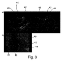
図3において、3つの尖底42、44及び46をマークするマーカの予備セットを調節するプロセスが、示される。上のセクションa)において、左冠尖(LCC)42、右冠尖(RCC)44及び無冠尖(NCC)46に対する予備マーカは、2Dx面心エコー画像内の大動脈弁尖の直交する2Dビュー上に配置される。下のセクションb)に見られるように、前記弁尖底のマーカの予備セットは、X線大動脈造影画像において弁尖底と良好に整列しない。大動脈内腔48は、患者に注入される造影剤の援助で可視である。前記心エコー画像を生成するのに使用されるプローブ40も、前記大動脈造影において可視である。
In FIG. 3, the process of adjusting a pre-set of markers that mark the three
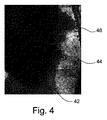
しかしながら、図4において、尖底42、44及び46を位置特定するためのX線大動脈造影フレームにおける自動フィーチャ検出探索の一例が、示される。前記底は、円内に示される。他のフィーチャの検出は、十分なフィルタ及びより小さな探索窓により除外されうる。
However, in FIG. 4, an example of an automatic feature detection search in an X-ray aortic imaging frame to locate the
図5において、本発明による方法は、ブロック志向の概略図に示される。基本的に、前記方法は、X線画像取得装置12を用いて2つの異なる視野角において心エコー撮像装置38の超音波プローブ40のX線蛍光透視画像の第1のセットを取得するステップ50と、処理ユニット30を用いて前記X線蛍光透視画像の第1のセットに基づいてライブ心エコー画像及びライブX線画像を位置合わせするステップ52と、後のX線フレームにおいて尖底を位置特定するステップ54と、前記尖底の特定された位置にマッチするようにマーカのセットを確立するステップ56と、X線画像取得装置12の最適な視野角を決定するステップ58であって、前記最適な視野角において前記マーカの第2のセットのマーカがX線視野において単一の線上にあり、互いから等間隔である、ステップと、前記決定された最適な視野角まで移動するようにX線画像取得装置12を制御するステップ60とを有する。
In FIG. 5, the method according to the invention is shown in a block-oriented schematic diagram. Basically, the method uses the X-ray image acquisition device 12 to acquire a first set of X-ray fluoroscopic images of the
しかしながら、位置特定するステップ54は、前記マーカのセットを確立するステップが、認識された尖底位置によってマーカの予備セットを調節することにより行われるように、オペレータにより与えられたマーカの予備セットの周りで心エコー画像又はX線画像において尖底位置を認識するステップ62により行われてもよい。このオプションは、「I」でマークされる。更に、尖底位置を認識するステップ62は、前記X線画像シーケンスの中心領域、特に前記X線画像シーケンスの第1のフレーム上の右冠尖のマーカ位置を中心とする領域において行われてもよい。
However, the locating
「II」でマークされる代替的な実施例において、位置特定するステップ54は、前記マーカのセットを形成するために大動脈弁の三次元モデルから弁尖底42、44、46の位置を抽出するステップ64により行われてもよい。
In an alternative embodiment marked “II”, the locating
本発明の他の典型的な実施例において、先行する実施例の1つによる方法の方法ステップを適切なシステム上で実行するように構成されることにより特徴づけられるコンピュータプログラム又はコンピュータプログラム要素が、提供される。 In another exemplary embodiment of the present invention, a computer program or computer program element characterized by being configured to execute the method steps of the method according to one of the preceding embodiments on a suitable system comprises: Provided.
前記コンピュータプログラム要素は、したがって、本発明の一次指令の一部であってもよいコンピュータユニットに記憶されてもよい。この計算ユニットは、上記の方法のステップを実行する又は実行を誘導するように構成されてもよい。更に、これは、上記の装置のコンポーネントを動作するように構成されてもよい。前記計算ユニットは、自動的に動作する及び/又はユーザのオーダを実行するように構成されることができる。コンピュータプログラムは、データプロセッサのワーキングメモリにロードされてもよい。前記データプロセッサは、本発明の方法を実行するように備えられてもよい。 Said computer program element may therefore be stored in a computer unit which may be part of the primary command of the present invention. This computing unit may be configured to perform or direct the execution of the method steps described above. In addition, it may be configured to operate the components of the apparatus described above. The computing unit may be configured to operate automatically and / or execute a user order. The computer program may be loaded into the working memory of the data processor. The data processor may be equipped to perform the method of the present invention.
本発明のこの典型的な実施例は、最初から本発明を使用するコンピュータプログラム及び更新を用いて既存のプログラムを、本発明を使用するプログラムにするコンピュータプログラムの両方をカバーする。 This exemplary embodiment of the present invention covers both computer programs that use the present invention from the beginning and computer programs that use updates to make existing programs a program that uses the present invention.
更に、前記コンピュータプログラム要素は、上記の方法の典型的な実施例の手順を満たすように全ての必要なステップを提供することができてもよい。 Further, the computer program element may be able to provide all necessary steps to satisfy the procedures of the exemplary embodiments of the method described above.
本発明の他の典型的な実施例によると、CD−ROMのようなコンピュータ可読媒体が、提示され、前記コンピュータ可読媒体は、先行するセクションにより記載されたコンピュータプログラム要素を記憶している。 According to another exemplary embodiment of the present invention, a computer readable medium, such as a CD-ROM, is presented, which stores the computer program elements described by the preceding section.
コンピュータプログラムは、他のハードウェアと一緒に又は一部として供給される光記憶媒体又は半導体媒体のような適切な媒体に記憶され及び/又は分配されてもよいが、インターネット又は他の有線若しくは無線電気通信システムを介するような他の形式で分配されてもよい。 The computer program may be stored and / or distributed on a suitable medium such as an optical storage medium or a semiconductor medium supplied together with or as part of other hardware, but also on the Internet or other wired or wireless It may be distributed in other forms, such as via a telecommunications system.
しかしながら、前記コンピュータプログラムは、ワールドワイドウェブのようなネットワーク上に提示されてもよく、このようなネットワークからデータプロセッサのワーキングメモリにダウンロードされることができる。本発明の他の典型的な実施例によると、コンピュータプログラム要素をダウンロード可能にする媒体が、提供され、前記コンピュータプログラム要素は、本発明の以前に記載された実施例の1つによる方法を実行するように構成される。 However, the computer program may be presented on a network such as the World Wide Web and can be downloaded from such a network to the working memory of the data processor. According to another exemplary embodiment of the present invention, a medium is provided that enables a computer program element to be downloaded, said computer program element performing a method according to one of the previously described embodiments of the present invention. Configured to do.
本発明の実施例が、異なる対象を参照して記載されていることに注意すべきである。特に、一部の実施例は、方法型請求項を参照して記載されるのに対し、他の実施例は、装置型請求項を参照して記載される。しかしながら、当業者は、上の及び以下の記載から、他に示されない限り、1つのタイプの対象に属するフィーチャのいかなる組み合わせに加えて、異なる対象に関するフィーチャ間のいかなる組み合わせも、本出願とともに開示されていると見なされると推測する。しかしながら、全てのフィーチャは、組み合わせられることができ、前記フィーチャの単純な合計以上である相乗効果を提供する。 It should be noted that embodiments of the present invention have been described with reference to different objects. In particular, some embodiments are described with reference to method type claims, while other embodiments are described with reference to device type claims. However, from the above and following descriptions, those skilled in the art will disclose with this application any combination between features relating to different objects, in addition to any combination of features belonging to one type of object, unless otherwise indicated. Guess that it is considered. However, all features can be combined, providing a synergy that is more than a simple sum of the features.
本発明は、図面及び先行する記載において詳細に図示及び記載されているが、このような図示及び記載は、例示的又は典型的であり、限定的ではないと見なされるべきである。本発明は、開示された実施例に限定されない。開示された実施例に対する他の変形は、図面、開示及び従属請求項の検討から、請求された発明を実施する当業者により理解及び達成されることができる。 While the invention has been illustrated and described in detail in the drawings and foregoing description, such illustration and description are to be considered illustrative or exemplary and not restrictive. The invention is not limited to the disclosed embodiments. Other variations to the disclosed embodiments can be understood and attained by those skilled in the art in practicing the claimed invention, from a study of the drawings, the disclosure, and the dependent claims.
請求項において、単語「有する」は、他の要素又はステップを除外せず、不定冠詞"a"又は"an"は、複数を除外しない。単一のプロセッサ又は他のユニットが、請求項に記載された複数のアイテムの機能を満たしてもよい。特定の方策が相互の異なる従属請求項に記載されているという単なる事実は、これらの方策の組み合わせが有利に使用されることができないことを示さない。請求項内のいかなる参照符号も、範囲を限定すると解釈されるべきではない。 In the claims, the word “comprising” does not exclude other elements or steps, and the indefinite article “a” or “an” does not exclude a plurality. A single processor or other unit may fulfill the functions of several items recited in the claims. The mere fact that certain measures are recited in mutually different dependent claims does not indicate that a combination of these measures cannot be used to advantage. Any reference signs in the claims should not be construed as limiting the scope.
10:医療ビューイングシステム
12:X線撮像システム
14:医療画像ビューイング装置
16:X線源
18:X線検出器
20:支持台
22:造影剤注入器
24:制御ユニット
26:計算ユニット
28:画像データ提供ユニット
30:処理ユニット
32:ディスプレイユニット
34:第1のディスプレイ
36:第2のディスプレイ
38:心エコー撮像装置
40:超音波プローブ
42:左冠尖(LCC)
44:右冠尖(RCC)
46:無冠尖(NCC)
48:大動脈内腔
50:X線蛍光透視画像の第1のセットを取得するステップ
52:ライブ心エコー及びX線画像を位置合わせするステップ
54:特徴的フィーチャのセットの位置を特定するステップ
56:マーカのセットを確立するステップ
58:最適な視野角を決定するステップ
60:X線撮像装置を制御するステップ
62:特徴的フィーチャの位置を認識するステップ
64:特徴的フィーチャのセットの位置を抽出するステップ
10: medical viewing system 12: X-ray imaging system 14: medical image viewing apparatus 16: X-ray source 18: X-ray detector 20: support base 22: contrast medium injector 24: control unit 26: calculation unit 28: Image data providing unit 30: processing unit 32: display unit 34: first display 36: second display 38: echocardiographic imaging device 40: ultrasonic probe 42: left coronary apex (LCC)
44: Right coronary apex (RCC)
46: No crown apex (NCC)
48: Aortic lumen 50: Obtaining a first set of X-ray fluoroscopy images Step 52: Aligning live echocardiograms and X-ray images Step 54: Locating a set of characteristic features Step 56: Step 58: Establishing a set of markers Step 58: Determining an optimal viewing angle Step 60: Controlling the X-ray imaging device Step 62: Recognizing the position of a characteristic feature Step 64: Extracting the position of a set of characteristic features Step
Claims (14)
Cアームにより可変回転角度から関心器官のライブX線画像を提供するX線画像取得装置と、
前記関心器官のライブ超音波画像を提供する超音波プローブを有する心エコー撮像装置と、
前記X線画像取得装置及び前記心エコー撮像装置に接続された処理ユニットと、
を有し、
前記医療ビューイングシステムが、2つの異なる回転角度からの前記関心器官及び前記超音波プローブのX線蛍光透視画像の第1のセットを取得し、
前記処理ユニットが、
前記X線蛍光透視画像の第1のセットに基づいて前記超音波プローブを位置特定することによりライブ心エコー画像及びライブX線画像を位置合わせし、
前記位置合わせの後のX線フレームの前記ライブX線画像において特徴的フィーチャのセットの位置を特定し、
前記特徴的フィーチャのセットのそれぞれの特定された位置にマッチするようにマーカのセットのそれぞれを確立し、
前記X線画像取得装置の最適な回転角度を決定し、前記最適な回転角度において前記マーカのセットのマーカがX線視野において所定の位置関係を有する、
医療ビューイングシステム。 In the medical viewing system,
An X-ray image acquisition device for providing a live X-ray image of an organ of interest from a variable rotation angle by a C-arm;
An echocardiography device having an ultrasound probe that provides a live ultrasound image of the organ of interest;
A processing unit connected to the X-ray image acquisition device and the echocardiography device;
Have
The medical viewing system acquires a first set of x-ray fluoroscopic images of the organ of interest and the ultrasound probe from two different rotation angles;
The processing unit is
Aligning the live echocardiogram and live X-ray image by locating the ultrasound probe based on the first set of X-ray fluoroscopic images;
Locating a set of characteristic features in the live X-ray image of the X-ray frame after the alignment;
Establishing each of the set of markers to match each identified location of the set of characteristic features;
Determining an optimum rotation angle of the X-ray image acquisition device, and the markers of the set of markers at the optimum rotation angle have a predetermined positional relationship in an X-ray field;
Medical viewing system.
請求項1に記載の医療ビューイングシステム。 The set of characteristic features has a pointed bottom;
The medical viewing system according to claim 1.
前記処理ユニットが、前記認識された位置によって前記マーカの予備セットを調節する、
請求項1乃至2のいずれか一項に記載の医療ビューイングシステム。 Locating the set of characteristic features comprises recognizing the position of the set of characteristic features in an echocardiogram or X-ray image around a preliminary set of markers provided by an operator;
The processing unit adjusts the preliminary set of markers according to the recognized position;
The medical viewing system according to claim 1.
請求項1乃至3のいずれか一項に記載の医療ビューイングシステム。 The processing unit recognizes the characteristic feature in a central region of the live X-ray image of the X-ray frame after the alignment ;
The medical viewing system according to any one of claims 1 to 3.
請求項1に記載の医療ビューイングシステム。 The processing unit extracts the position of the set of characteristic features from a three-dimensional model of at least one organ of interest to form the set of markers;
The medical viewing system according to claim 1.
請求項5に記載の医療ビューイングシステム。 The processing unit automatically fits a natural organ in the image when a stored or live aortic angiographic image is received by the processing unit;
The medical viewing system according to claim 5.
X線画像取得装置が、2つの異なる回転角度からの関心器官及び心エコー撮像装置の超音波プローブのX線蛍光透視画像の第1のセットを取得するステップと、
処理ユニットが、前記X線蛍光透視画像の第1のセットに基づいて前記超音波プローブを位置特定することによりライブ心エコー画像及びライブX線画像を位置合わせするステップと、
前記処理ユニットが、前記位置合わせの後のX線フレームの前記ライブX線画像において特徴的フィーチャのセットの位置を特定するステップと、
前記処理ユニットが、前記特徴的フィーチャのセットのそれぞれの特定された位置にマッチするようにマーカのセットのそれぞれを確立するステップと、
前記処理ユニットが、前記X線画像取得装置の最適な回転角度を決定するステップであって、前記最適な回転角度において前記マーカのセットのマーカがX線視野において所定の位置関係を有する、ステップと、
を有する方法。 In a method of operating a medical viewing system for providing medical images, the method comprises:
An X-ray image acquisition device acquiring a first set of X-ray fluoroscopic images of an ultrasound probe of an organ of interest and an echocardiograph from two different rotation angles;
A processing unit aligning a live echocardiogram image and a live X-ray image by locating the ultrasound probe based on the first set of X-ray fluoroscopic images;
The processing unit locating a set of characteristic features in the live X-ray image of the X-ray frame after the alignment;
The processing unit establishing each of the set of markers to match each identified location of the set of characteristic features;
The processing unit determining an optimal rotation angle of the X-ray image acquisition device, wherein the markers of the set of markers have a predetermined positional relationship in an X-ray field at the optimal rotation angle; ,
Having a method.
請求項7に記載の方法。 Locating a set of characteristic features in the live x-ray image of the x-ray frame after the alignment comprises locating a leaflet.
The method of claim 7.
前記処理ユニットが、前記認識された位置によって前記マーカの予備セットを調節するステップと、
を有する、請求項7又は8に記載の方法。 The processing unit recognizes the position of the set of characteristic features in the live echocardiogram or the live X-ray image of the X-ray frame after registration around a pre-set of markers provided by an operator Steps,
The processing unit adjusting the preliminary set of markers according to the recognized position;
The method according to claim 7 or 8, comprising:
請求項7乃至9のいずれか一項に記載の方法。 Recognizing the position of the set of characteristic features is performed in a central region of the live X-ray image of the X-ray frame after the alignment;
10. A method according to any one of claims 7-9.
を有する、請求項7に記載の方法。 The processing unit extracting the position of the set of characteristic features from a three-dimensional model of at least one organ of interest to form the set of markers;
The method of claim 7, comprising:
を有する、請求項11に記載の方法。 The processing unit automatically fitting a natural organ in the stored or live aortic angiogram image received by the processing unit;
The method of claim 11, comprising:
Applications Claiming Priority (3)
| Application Number | Priority Date | Filing Date | Title |
|---|---|---|---|
| EP13194184.1 | 2013-11-25 | ||
| EP13194184 | 2013-11-25 | ||
| PCT/EP2014/073769 WO2015074869A1 (en) | 2013-11-25 | 2014-11-05 | Medical viewing system with a viewing angle optimization function |
Publications (3)
| Publication Number | Publication Date |
|---|---|
| JP2017500079A JP2017500079A (en) | 2017-01-05 |
| JP2017500079A5 JP2017500079A5 (en) | 2017-12-14 |
| JP6397018B2 true JP6397018B2 (en) | 2018-09-26 |
Family
ID=49712930
Family Applications (1)
| Application Number | Title | Priority Date | Filing Date |
|---|---|---|---|
| JP2016530863A Active JP6397018B2 (en) | 2013-11-25 | 2014-11-05 | Medical viewing system with viewing angle optimization function |
Country Status (5)
| Country | Link |
|---|---|
| US (1) | US10813615B2 (en) |
| EP (1) | EP3091928B1 (en) |
| JP (1) | JP6397018B2 (en) |
| CN (1) | CN105992556B (en) |
| WO (1) | WO2015074869A1 (en) |
Families Citing this family (5)
| Publication number | Priority date | Publication date | Assignee | Title |
|---|---|---|---|---|
| JP6499328B2 (en) | 2015-06-17 | 2019-04-10 | コーニンクレッカ フィリップス エヌ ヴェKoninklijke Philips N.V. | Determination of C-arm angulation for valve positioning |
| JP6692906B2 (en) | 2015-12-18 | 2020-05-13 | コーニンクレッカ フィリップス エヌ ヴェKoninklijke Philips N.V. | Image processing for improved marker placement for linear image features |
| JP6849966B2 (en) * | 2016-11-21 | 2021-03-31 | 東芝エネルギーシステムズ株式会社 | Medical image processing equipment, medical image processing methods, medical image processing programs, motion tracking equipment and radiation therapy systems |
| US20180235573A1 (en) * | 2017-02-21 | 2018-08-23 | General Electric Company | Systems and methods for intervention guidance using a combination of ultrasound and x-ray imaging |
| US20180235701A1 (en) * | 2017-02-21 | 2018-08-23 | General Electric Company | Systems and methods for intervention guidance using pre-operative planning with ultrasound |
Family Cites Families (19)
| Publication number | Priority date | Publication date | Assignee | Title |
|---|---|---|---|---|
| US8565860B2 (en) * | 2000-08-21 | 2013-10-22 | Biosensors International Group, Ltd. | Radioactive emission detector equipped with a position tracking system |
| JP2004329729A (en) * | 2003-05-12 | 2004-11-25 | Toshiba Corp | X-ray diagnostic apparatus and radiographing method |
| US7813785B2 (en) * | 2003-07-01 | 2010-10-12 | General Electric Company | Cardiac imaging system and method for planning minimally invasive direct coronary artery bypass surgery |
| JP2005102987A (en) * | 2003-09-30 | 2005-04-21 | Hoken Kagi Kofun Yugenkoshi | Extracorporeal calculus crushing apparatus and method for tracing and positioning calculus thereby |
| DE602004024580D1 (en) * | 2003-12-22 | 2010-01-21 | Koninkl Philips Electronics Nv | SYSTEM FOR LEADING A MEDICAL INSTRUMENT IN THE BODY OF A PATIENT |
| DE102005032523B4 (en) * | 2005-07-12 | 2009-11-05 | Siemens Ag | Method for the pre-interventional planning of a 2D fluoroscopy projection |
| CN102316816B (en) * | 2009-02-12 | 2014-11-05 | 皇家飞利浦电子股份有限公司 | System for determining the orientation of a catheter |
| RU2556783C2 (en) * | 2009-12-09 | 2015-07-20 | Конинклейке Филипс Электроникс Н.В. | Combination of ultrasound and x-ray systems |
| CN102713976B (en) * | 2010-01-12 | 2017-05-24 | 皇家飞利浦电子股份有限公司 | Navigating an interventional device |
| US8494245B2 (en) * | 2010-03-09 | 2013-07-23 | Siemens Aktiengesellschaft | System and method for guiding transcatheter aortic valve implantations based on interventional C-Arm CT imaging |
| WO2011148299A1 (en) * | 2010-05-27 | 2011-12-01 | Koninklijke Philips Electronics N.V. | Determining the specific orientation of an object |
| DE102011079561B4 (en) | 2011-07-21 | 2018-10-18 | Siemens Healthcare Gmbh | Method and X-ray device for timely presentation of a moving section of a body, computer program and data carrier |
| US9155470B2 (en) * | 2012-01-24 | 2015-10-13 | Siemens Aktiengesellschaft | Method and system for model based fusion on pre-operative computed tomography and intra-operative fluoroscopy using transesophageal echocardiography |
| US20150223773A1 (en) * | 2014-02-11 | 2015-08-13 | Siemens Medical Solutions Usa, Inc. | Method and Apparatus for Image Fusion Based Planning of C-Arm Angulation for Structural Heart Disease |
| JP6659562B2 (en) * | 2014-03-21 | 2020-03-04 | コーニンクレッカ フィリップス エヌ ヴェKoninklijke Philips N.V. | Medical viewing system with viewing plane determination |
| JP6232147B2 (en) * | 2014-05-16 | 2017-11-15 | コーニンクレッカ フィリップス エヌ ヴェKoninklijke Philips N.V. | Apparatus for correcting TEE probe imaging in X-ray data |
| JP6505444B2 (en) * | 2015-01-16 | 2019-04-24 | キヤノンメディカルシステムズ株式会社 | Observation device |
| US10282638B2 (en) * | 2015-07-29 | 2019-05-07 | Siemens Healthcare Gmbh | Tracking for detection of TEE probe in fluoroscopy medical imaging |
| US10515449B2 (en) * | 2016-11-04 | 2019-12-24 | Siemens Medical Solutions Usa, Inc. | Detection of 3D pose of a TEE probe in x-ray medical imaging |
-
2014
- 2014-11-05 EP EP14793846.8A patent/EP3091928B1/en active Active
- 2014-11-05 WO PCT/EP2014/073769 patent/WO2015074869A1/en active Application Filing
- 2014-11-05 JP JP2016530863A patent/JP6397018B2/en active Active
- 2014-11-05 US US15/038,677 patent/US10813615B2/en active Active
- 2014-11-05 CN CN201480064436.5A patent/CN105992556B/en active Active
Also Published As
| Publication number | Publication date |
|---|---|
| CN105992556A (en) | 2016-10-05 |
| US20160302754A1 (en) | 2016-10-20 |
| CN105992556B (en) | 2019-06-04 |
| EP3091928A1 (en) | 2016-11-16 |
| US10813615B2 (en) | 2020-10-27 |
| EP3091928B1 (en) | 2019-04-03 |
| WO2015074869A1 (en) | 2015-05-28 |
| JP2017500079A (en) | 2017-01-05 |
Similar Documents
| Publication | Publication Date | Title |
|---|---|---|
| US11642173B2 (en) | Image-based navigation system and method of using same | |
| JP6492188B2 (en) | Tracking-based 3D model enhancements | |
| US8625865B2 (en) | Method and apparatus for navigating a therapeutic device to a location | |
| US10524865B2 (en) | Combination of 3D ultrasound and computed tomography for guidance in interventional medical procedures | |
| JP6397018B2 (en) | Medical viewing system with viewing angle optimization function | |
| JP7019694B2 (en) | Selection of medical equipment for use in medical procedures | |
| JP2009213892A (en) | Method and apparatus for conducting an interventional procedure involving heart valves | |
| KR101458585B1 (en) | Radiopaque Hemisphere Shape Maker for Cardiovascular Diagnosis and Procedure Guiding Image Real Time Registration | |
| US10402990B2 (en) | Medical viewing system with a viewing plane determination | |
| US20230139348A1 (en) | Ultrasound image-based guidance of medical instruments or devices | |
| AU2018204573A1 (en) | Marker placement | |
| JP7157074B2 (en) | Navigation platform for medical devices, especially cardiac catheters | |
| Lang et al. | Surface-based CT–TEE registration of the aortic root | |
| US9036880B2 (en) | High-resolution three-dimensional medical imaging with dynamic real-time information | |
| US20120296196A1 (en) | Method for assisting a person performing a minimally invasive intervention with a catheter involving a puncture of a septum and x-ray device | |
| WO2018115200A1 (en) | Navigation platform for a medical device, particularly an intracardiac catheter | |
| van den Broek et al. | 3D hybrid imaging for structural and congenital heart interventions in the Cath lab | |
| Jelnin et al. | Use of computed tomography to guide mitral interventions | |
| Linte et al. | From pre-operative cardiac modeling to intra-operative virtual environments for surgical guidance: an in vivo study | |
| WUNDERLICH et al. | Integrated Multimodality Imaging for Structural Heart Disease Intervention |
Legal Events
| Date | Code | Title | Description |
|---|---|---|---|
| RD04 | Notification of resignation of power of attorney |
Free format text: JAPANESE INTERMEDIATE CODE: A7424 Effective date: 20170214 |
|
| A521 | Request for written amendment filed |
Free format text: JAPANESE INTERMEDIATE CODE: A523 Effective date: 20171101 |
|
| A621 | Written request for application examination |
Free format text: JAPANESE INTERMEDIATE CODE: A621 Effective date: 20171101 |
|
| A871 | Explanation of circumstances concerning accelerated examination |
Free format text: JAPANESE INTERMEDIATE CODE: A871 Effective date: 20171101 |
|
| A975 | Report on accelerated examination |
Free format text: JAPANESE INTERMEDIATE CODE: A971005 Effective date: 20171115 |
|
| A131 | Notification of reasons for refusal |
Free format text: JAPANESE INTERMEDIATE CODE: A131 Effective date: 20171121 |
|
| A521 | Request for written amendment filed |
Free format text: JAPANESE INTERMEDIATE CODE: A523 Effective date: 20180207 |
|
| A131 | Notification of reasons for refusal |
Free format text: JAPANESE INTERMEDIATE CODE: A131 Effective date: 20180327 |
|
| A521 | Request for written amendment filed |
Free format text: JAPANESE INTERMEDIATE CODE: A523 Effective date: 20180619 |
|
| TRDD | Decision of grant or rejection written | ||
| A01 | Written decision to grant a patent or to grant a registration (utility model) |
Free format text: JAPANESE INTERMEDIATE CODE: A01 Effective date: 20180807 |
|
| A61 | First payment of annual fees (during grant procedure) |
Free format text: JAPANESE INTERMEDIATE CODE: A61 Effective date: 20180830 |
|
| R150 | Certificate of patent or registration of utility model |
Ref document number: 6397018 Country of ref document: JP Free format text: JAPANESE INTERMEDIATE CODE: R150 |
|
| R250 | Receipt of annual fees |
Free format text: JAPANESE INTERMEDIATE CODE: R250 |
|
| R250 | Receipt of annual fees |
Free format text: JAPANESE INTERMEDIATE CODE: R250 |
|
| R250 | Receipt of annual fees |
Free format text: JAPANESE INTERMEDIATE CODE: R250 |