JP6367018B2 - Sterile drape - Google Patents
Sterile drape Download PDFInfo
- Publication number
- JP6367018B2 JP6367018B2 JP2014127685A JP2014127685A JP6367018B2 JP 6367018 B2 JP6367018 B2 JP 6367018B2 JP 2014127685 A JP2014127685 A JP 2014127685A JP 2014127685 A JP2014127685 A JP 2014127685A JP 6367018 B2 JP6367018 B2 JP 6367018B2
- Authority
- JP
- Japan
- Prior art keywords
- microscope
- medical observation
- unit
- attachment portion
- cylindrical
- Prior art date
- Legal status (The legal status is an assumption and is not a legal conclusion. Google has not performed a legal analysis and makes no representation as to the accuracy of the status listed.)
- Active
Links
Images


Classifications
-
- A—HUMAN NECESSITIES
- A61—MEDICAL OR VETERINARY SCIENCE; HYGIENE
- A61B—DIAGNOSIS; SURGERY; IDENTIFICATION
- A61B46/00—Surgical drapes
- A61B46/10—Surgical drapes specially adapted for instruments, e.g. microscopes
-
- A—HUMAN NECESSITIES
- A61—MEDICAL OR VETERINARY SCIENCE; HYGIENE
- A61B—DIAGNOSIS; SURGERY; IDENTIFICATION
- A61B90/00—Instruments, implements or accessories specially adapted for surgery or diagnosis and not covered by any of the groups A61B1/00 - A61B50/00, e.g. for luxation treatment or for protecting wound edges
- A61B90/50—Supports for surgical instruments, e.g. articulated arms
-
- A—HUMAN NECESSITIES
- A61—MEDICAL OR VETERINARY SCIENCE; HYGIENE
- A61B—DIAGNOSIS; SURGERY; IDENTIFICATION
- A61B90/00—Instruments, implements or accessories specially adapted for surgery or diagnosis and not covered by any of the groups A61B1/00 - A61B50/00, e.g. for luxation treatment or for protecting wound edges
- A61B90/20—Surgical microscopes characterised by non-optical aspects
Landscapes
- Health & Medical Sciences (AREA)
- Surgery (AREA)
- Life Sciences & Earth Sciences (AREA)
- Engineering & Computer Science (AREA)
- Biomedical Technology (AREA)
- Heart & Thoracic Surgery (AREA)
- Medical Informatics (AREA)
- Molecular Biology (AREA)
- Animal Behavior & Ethology (AREA)
- General Health & Medical Sciences (AREA)
- Public Health (AREA)
- Veterinary Medicine (AREA)
- Nuclear Medicine, Radiotherapy & Molecular Imaging (AREA)
- Oral & Maxillofacial Surgery (AREA)
- Pathology (AREA)
- Microscoopes, Condenser (AREA)
Description
本発明は、被観察体の微小部位を観察する医療用観察装置に適用される滅菌ドレープに関する。 The present invention relates to a sterilized drape applied to a medical observation apparatus for observing a minute part of an object to be observed.
従来、被観察体である患者の脳や心臓等における微小部位を観察する医療用観察装置として、顕微鏡部と、顕微鏡部を移動可能に支持するアームとを備えた手術用顕微鏡が知られている(例えば、特許文献1を参照)。この手術用顕微鏡では、顕微鏡部を移動させる場合、ユーザはアームのグリップ部に設けられたアーム操作用のスイッチを押しながら、アームを所望の位置まで移動させる。 2. Description of the Related Art Conventionally, a surgical microscope having a microscope unit and an arm that movably supports the microscope unit is known as a medical observation device for observing a minute part of a patient's brain or heart as an object to be observed. (For example, see Patent Document 1). In this surgical microscope, when moving the microscope unit, the user moves the arm to a desired position while pressing a switch for arm operation provided on the grip portion of the arm.
手術用顕微鏡等の医療用観察装置を用いて患者の手術を行う際、その表面の滅菌状態を保持するために滅菌ドレープが使用される(例えば、特許文献2および3を参照)。滅菌ドレープは、ビニール等の材料からなる袋状の部材であり、医療用観察装置を被覆するように装着される。 When a patient is operated using a medical observation apparatus such as a surgical microscope, a sterilized drape is used to maintain the sterilized state of the surface (see, for example, Patent Documents 2 and 3). The sterilized drape is a bag-like member made of a material such as vinyl, and is mounted so as to cover the medical observation apparatus.
ところで、上述した特許文献1のように、顕微鏡部に対する動作指示の入力を受け付ける入力部がグリップ部に設けられている場合、このグリップ部に滅菌ドレープを被せると、ユーザがグリップ部を把持したときに滅菌ドレープとグリップ部との間に滑りを生じやすかった。このような場合、ユーザは思い通りにスイッチ入力を行うことができず、グリップ部の操作性が損なわれてしまうおそれがあった。
By the way, when the input part which receives the input of the operation | movement instruction | indication with respect to a microscope part is provided in the grip part like
本発明は、上記に鑑みてなされたものであって、適用対象である医療用観察装置において、操作用の入力部が設けられたグリップ部の操作性を良好に保つことができる滅菌ドレープを提供することを目的とする。 The present invention has been made in view of the above, and provides a sterilized drape capable of maintaining good operability of a grip portion provided with an input portion for operation in a medical observation apparatus that is an application target. The purpose is to do.
上述した課題を解決し、目的を達成するために、本発明に係る滅菌ドレープは、被観察体の微小部位を拡大して撮像する顕微鏡部と、前記顕微鏡部に対する動作指示の入力を受け付ける入力部と、該入力部の少なくとも一部が表面に設けられた棒状のグリップ部とを備えた医療用観察装置を被覆することによって該医療用観察装置の滅菌状態を保持する滅菌ドレープであって、前記医療用観察装置を被覆した状態で前記グリップ部に固定して取り付けられる取付部を備えたことを特徴とする。 In order to solve the above-described problems and achieve the object, the sterilization drape according to the present invention includes a microscope unit that magnifies and images a minute part of an object to be observed, and an input unit that receives an operation instruction input to the microscope unit. And a sterilizing drape that maintains a sterilized state of the medical observation device by covering a medical observation device provided with a rod-shaped grip portion provided on the surface of at least a part of the input unit, An attachment portion that is fixedly attached to the grip portion in a state of covering the medical observation device is provided.
本発明に係る滅菌ドレープは、上記発明において、前記取付部は、前記医療用観察装置を被覆した状態で該医療用観察装置と対向しない表面側が前記グリップ部に対して突起した形状をなすことを特徴とする。 In the sterilization drape according to the present invention, in the above invention, the attachment portion has a shape in which a surface side that does not face the medical observation device projects from the grip portion in a state of covering the medical observation device. Features.
本発明に係る滅菌ドレープは、上記発明において、弾性部材からなり、前記医療用観察装置を被覆した状態で前記グリップ部に設けられた前記入力部の少なくとも一部を被覆する入力部カバーをさらに備えたことを特徴とする。 The sterilization drape according to the present invention further includes an input part cover that is made of an elastic member and covers at least a part of the input part provided on the grip part in a state of covering the medical observation device. It is characterized by that.
本発明に係る滅菌ドレープは、上記発明において、前記医療用観察装置は、前記顕微鏡部が柱状をなして前記グリップ部としての機能を有し、前記取付部は、前記顕微鏡部に取り付けられることを特徴とする。 In the sterilization drape according to the present invention, in the above-described invention, the medical observation apparatus may be configured such that the microscope unit has a columnar shape and functions as the grip unit, and the attachment unit is attached to the microscope unit. Features.
本発明に係る滅菌ドレープは、上記発明において、前記取付部は、前記グリップ部の表面に嵌合可能な形状をなすことを特徴とする。 The sterilization drape according to the present invention is characterized in that, in the above invention, the attachment portion has a shape that can be fitted to a surface of the grip portion.
本発明に係る滅菌ドレープは、上記発明において、前記取付部は、帯状をなし、帯長さ方向の両端部に他の端部と係合する係合部を有することを特徴とする。 The sterilizing drape according to the present invention is characterized in that, in the above-mentioned invention, the attachment portion has a band shape and has engaging portions that engage with other end portions at both end portions in the band length direction.
本発明に係る滅菌ドレープは、上記発明において、前記取付部は、弾性部材からなることを特徴とする。 The sterilizing drape according to the present invention is characterized in that, in the above invention, the attachment portion is made of an elastic member.
本発明に係る滅菌ドレープは、上記発明において、前記取付部は、前記顕微鏡部の外径より小さい径の筒状をなす弾性部材からなることを特徴とする。 The sterilizing drape according to the present invention is characterized in that, in the above-mentioned invention, the attachment portion is made of an elastic member having a cylindrical shape having a diameter smaller than the outer diameter of the microscope portion.
本発明に係る滅菌ドレープは、上記発明において、前記取付部は、前記顕微鏡部の外径より小さい径の筒状をなす弾性部材からなる筒状部と、前記筒状部の高さ方向の端部であって前記顕微鏡部の先端に対応する端部に設けられ、前記顕微鏡部が前記被観察体からの光を集光する開口面を保護するカバーガラスと、を有することを特徴とする。 In the sterilization drape according to the present invention, in the above invention, the attachment portion includes a cylindrical portion made of an elastic member having a cylindrical diameter smaller than an outer diameter of the microscope portion, and an end in the height direction of the cylindrical portion. And a cover glass that is provided at an end corresponding to the tip of the microscope unit, and the microscope unit protects an opening surface that collects light from the object to be observed.
本発明に係る滅菌ドレープは、上記発明において、前記筒状部は、前記カバーガラスの外周部分に、径方向に突出したフランジ部を有することを特徴とする。 The sterilizing drape according to the present invention is characterized in that, in the above-mentioned invention, the cylindrical part has a flange part projecting in a radial direction on an outer peripheral part of the cover glass.
本発明に係る滅菌ドレープは、上記発明において、前記取付部は、前記顕微鏡部に対して先に挿入する側から切り込んだスリットを形成したことを特徴とする。 The sterilizing drape according to the present invention is characterized in that, in the above-mentioned invention, the attachment portion is formed with a slit cut from a side to be inserted first with respect to the microscope portion.
本発明に係る滅菌ドレープは、上記発明において、前記医療用観察装置は、前記顕微鏡部が柱状をなして前記グリップ部としての機能を有し、2つのアーム部および該2つのアーム部の一方を他方に対して回動可能に連結する関節部からなる組を少なくとも一組有し、先端部で前記顕微鏡部を該顕微鏡部の高さ方向の軸のまわりに回動可能に支持する支持部と、前記顕微鏡部の側面であって前記撮像信号に基づく画像の上方に対応する側面に設けられ、前記アーム部の回動を許容する操作入力を受け付けるアーム操作スイッチと、を備え、前記入力部は、前記アーム操作スイッチを含むことを特徴とする。 In the sterilization drape according to the present invention, in the above invention, the medical observation apparatus is configured such that the microscope section has a columnar shape and functions as the grip section, and has two arm sections and one of the two arm sections. A support portion that has at least one set of joint portions that are rotatably connected to the other, and that supports the microscope portion at a tip portion so as to be rotatable around an axis in a height direction of the microscope portion; An arm operation switch that is provided on a side surface of the microscope unit and corresponding to an upper side of an image based on the imaging signal, and that receives an operation input that allows the arm unit to rotate, and the input unit includes: The arm operation switch is included.
本発明によれば、医療用観察装置を被覆した状態でグリップ部に固定して取り付けられる取付部を備えたため、適用対象である医療用観察装置において、操作用の入力部が設けられたグリップ部の操作性を良好に保つことが可能となる。 According to the present invention, since the medical observation device is provided with the attachment portion that is fixed and attached to the grip portion in a state of covering the medical observation device, the grip portion provided with the operation input portion in the medical observation device that is an application target This makes it possible to maintain good operability.
以下、添付図面を参照して、本発明を実施するための形態(以下、「実施の形態」という)を説明する。なお、図面はあくまで模式的なものであり、図面の相互間においても互いの寸法の関係や比率が異なる部分が含まれる場合がある。 DESCRIPTION OF EMBODIMENTS Hereinafter, embodiments for carrying out the present invention (hereinafter referred to as “embodiments”) will be described with reference to the accompanying drawings. Note that the drawings are merely schematic, and there are cases in which portions having different dimensional relationships and ratios are included between the drawings.
(実施の形態1)
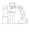
図1は、本発明の実施の形態1に係る滅菌ドレープの構成および使用態様を示す図である。同図に示す滅菌ドレープ1は、被観察体の微細構造を拡大して撮像する顕微鏡としての機能を有する医療用観察装置(以下、観察装置という)2を被覆するように被せられ、観察装置2の表面の滅菌状態を保持する。滅菌ドレープ1の本体は、ビニール等の材料を用いて構成され、観察装置2の形状に適合する袋状の異形形状を有する。
(Embodiment 1)
FIG. 1 is a diagram showing the configuration and usage of a sterilized drape according to
図1は、術者201が患者202の手術を行っている状況を示している。図1において、表示装置3は、観察装置2が撮像した患者202の術部の拡大画像を表示している。術者201は、表示装置3が表示する患者202の術部の拡大画像を見ながら手術を行っている。
FIG. 1 shows a situation where an
観察装置2は、床面上を移動可能なベース部4と、2つのアーム部および該2つのアーム部の一方を他方に対して回動可能に連結する関節部からなる組を複数有し、ベース部4に支持される支持部5と、支持部5の先端に設けられて被観察体の微小部位を拡大して撮像する円柱状の顕微鏡部6と、を備える。
The observation apparatus 2 has a plurality of sets each including a base portion 4 that can move on the floor, two arm portions, and a joint portion that rotatably connects one of the two arm portions to the other. A
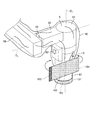
図2は、観察装置2の先端部に装着される滅菌ドレープ1の要部の構成ならびに観察装置2の先端部における支持部5および顕微鏡部6の構成を示す拡大斜視図である。
FIG. 2 is an enlarged perspective view showing the configuration of the main part of the
まず、支持部5の先端部の構成を説明する。支持部5は、先端側で顕微鏡部6を回動可能に支持する第1関節部51と、第1関節部51に固定され、第1関節部51の側面から延びる第1アーム部52と、先端側で第1アーム部52を回動可能に保持する第2関節部53と、先端部が第2関節部53に固定される第2アーム部54とを有する。
First, the structure of the front-end | tip part of the
第1関節部51は円筒状をなし、高さ方向の中心軸である第1軸O1のまわりに回動可能に顕微鏡部6を保持する。
第1アーム部52は、第1関節部51の側面から第1軸O1と直交する方向に延びる形状をなす。
第2関節部53は円筒状をなし、高さ方向の中心軸であり、かつ第1軸O1と直交する軸である第2軸O2のまわりに回動可能に第1アーム部52を保持する。
第2アーム部54は、第2軸O2と直交する方向に延びる形状をなす。
The first
The
The
The
第2アーム部54の基端側からベース部4に至る部分には、複数の関節部およびアーム部が設けられている(図1を参照)。なお、支持部5は、2つのアーム部および該2つのアーム部の一方を他方に対して回動可能に連結する関節部からなる組を少なくとも一組有していればよい。このため、第2アーム部54の基端側からベース部4に至る部分の構成は、適宜変更することが可能である。
A plurality of joint portions and arm portions are provided in a portion from the base end side of the
第1関節部51および第2関節部53は、顕微鏡部6および第1アーム部52の回動をそれぞれ禁止する電磁ブレーキを有する。各電磁ブレーキは、顕微鏡部6に設けられるアーム操作スイッチ63(後述)が押下された状態で解除され、顕微鏡部6および第1アーム部52の回動が許容される。なお、電磁ブレーキの代わりにエアブレーキを適用してもよい。
The first
支持部5には、複数のケーブルを収容可能な中空部が形成されている。このため、観察装置2の外部にケーブルが露出することなく、ケーブルに人や物が引っかかってしまうのを防止することができる。また、複数のケーブルを本体外部で引き回すよりも小型化することができ、術者201の視界の妨げにもならない。
The
次に、顕微鏡部6の構成を説明する。図3は、図2の矢視A方向(第2軸O2と平行な方向)の側面図である。顕微鏡部6は、円筒状をなす筒状部61と、筒状部61の中空部に設けられ、被観察体の像を拡大して撮像する撮像部62と、第1関節部51および第2関節部53における電磁ブレーキを解除して各関節部の回動を許容する操作入力を受け付けるアーム操作スイッチ63と、撮像部62における拡大倍率を変更する操作入力を受け付ける変倍スイッチ64と、被観察体までの焦点距離を変更する操作入力を受け付ける焦点距離変更スイッチ65と、を有する。
Next, the configuration of the
筒状部61は、第1関節部51よりも径が小さい円筒状をなしており、下端部の開口面には、撮像部62を保護するカバーガラスが設けられている(図示せず)。なお、筒状部61の形状は円筒状に限られるわけではなく、多角筒状をなしていてもよい。
The
撮像部62は、光軸が第1軸O1と一致するようにそれぞれ配置される複数のレンズを有し、被観察体からの光を集光して結像する光学系621と、光学系621が集光した光を受光して光電変換することによって撮像信号を生成する撮像素子622とを有する。
The
光学系621は、複数のレンズを有し、変倍スイッチ64の操作に応じて被観察体像の拡大倍率を変更可能であるとともに、焦点距離変更スイッチ65の操作に応じて被観察体までの焦点距離を変更可能である。
The
撮像素子622は、CCD(Charge Coupled Device)またはCMOS(Complementary Metal Oxide Semiconductor)を用いて構成される。撮像素子622が出力する撮像信号は、支持部5の内部空間に設けられる伝送ケーブルを介して表示用の画像データを生成する画像生成装置(図示せず)へ伝送される。
The
撮像部62は、第1関節部51の内部まで入り込んでいる。図3では、筒状部61および第1関節部51の中空部に設置される光学系621および撮像素子622を破線で模式的に示している。また、図3では、顕微鏡部6のうち第1関節部51の内部に入り込んで第1関節部51に対して筒状部61とともに回動する部分を1点鎖線で模式的に示している。
The
アーム操作スイッチ63は、押しボタン式のスイッチである。術者201がアーム操作スイッチ63を押下している間、第1関節部51および第2関節部53の電磁ブレーキが解除される。術者201は、筒状部61の側面のうち、変倍スイッチ64および焦点距離変更スイッチ65が設けられる側面と向かい合って顕微鏡部6を操作する。
The
変倍スイッチ64は、拡大倍率を大きくするズームインスイッチ641と、拡大倍率を小さくするズームアウトスイッチ642とを有する。
焦点距離変更スイッチ65は、被観察体までの焦点距離を遠くする遠景フォーカススイッチ651と、被観察体までの焦点距離を近くする近景フォーカススイッチ652とを有する。
The
The focal
以上の構成を有する顕微鏡部6は、術者201が顕微鏡部6の視野を移動させる際に術者201が把持して操作を行うグリップ部としての機能を兼備している。
The
次に、滅菌ドレープ1のうち、観察装置2の先端部に装着される部分の構成を説明する。図2に示すように、滅菌ドレープ1は、顕微鏡部6の筒状部61の先端に取り付けられ、顕微鏡部6が被観察体からの光を集光する開口面を保護するカバーガラス(図示せず)が取り付けられた円筒状の開口カバー11と、筒状部61の側面のうち、筒状部61の高さ方向に沿ってアーム操作スイッチ63よりも第1関節部51から遠い側面の部分に固定して取り付けられる取付部12と、を有する。
Next, the configuration of the portion of the sterilized
図4は、図2の矢視B方向(第1軸O1および第2軸O2と直交する方向)の側面図である。取付部12は、滅菌ドレープ1の袋状をなす本体の外表面側に連なって設けられる2つの突起部121、122を有する。突起部121、122は、筒状部61に取り付けられた状態で、筒状部61の表面において該筒状部61の高さ方向に沿って並ぶように配設される。取付部12は、滅菌ドレープ1の本体をなすビニールよりも硬質の弾性部材を用いて構成され、筒状部61の表面に固定して取り付けられる。弾性部材は、外部から接触する物体(例えば術者201の手)の滑りを防止することが可能な材料からなる。なお、開口カバー11のカバーガラス以外の部分も、取付部12と同様の材料から構成される。
FIG. 4 is a side view in the direction of arrow B in FIG. 2 (direction orthogonal to the first axis O 1 and the second axis O 2 ). The
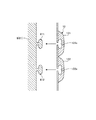
図5は、取付部12の顕微鏡部6(筒状部61)への取付方法の概要を模式的に示す図である。突起部121、122の裏面(滅菌ドレープ1を顕微鏡部6に装着した状態で顕微鏡部6と対向する面)には取付凹部121a、122aがそれぞれ形成されている。取付凹部121a、122aは、筒状部61の表面において、筒状部61の高さ方向(図5における上下方向)に沿って並べて設けられた2つの取付凸部611、612にそれぞれ嵌合される。これにより、取付部12が筒状部61に対して固定して取り付けられる。
FIG. 5 is a diagram schematically showing an outline of a method for attaching the
滅菌ドレープ1を観察装置2に被せて装着する際には、開口カバー11を筒状部61の先端に取り付けた後、取付凹部121a、122aを取付凸部611、612にそれぞれ嵌合させることにより、滅菌ドレープ1を観察装置2の先端部に対して装着する。
When mounting the sterilized
なお、取付部12の形状は上述した形状に限定されるわけではない。また、取付部12に突起部を設けた場合の突起部の数も上述した2つに限定されるわけではない。
In addition, the shape of the attaching
図6は、術者201が顕微鏡部6を操作する状況を模式的に示す図である。術者201は、筒状部61の側面のうち、変倍スイッチ64および焦点距離変更スイッチ65が設けられる側面と向かい合って顕微鏡部6を操作する。この際、術者201は、顕微鏡部6を右手211で把持した状態で、アーム操作スイッチ63を人差し指(または中指または薬指)で押下しながら支持部5を操作する。このため、顕微鏡部6を自然に握ったままアーム操作スイッチ63を押下して支持部5を操作することができる。
FIG. 6 is a diagram schematically illustrating a situation where the
術者201は、図1に示すように、表示装置3が表示する画像(顕微鏡部6が撮像する画像)を目視しながら、顕微鏡部6のアーム操作スイッチ63を押下した状態で顕微鏡部6を把持して所望の位置まで移動させる。術者201は、顕微鏡部6の視野を決定した後、アーム操作スイッチ63から指を離す。これにより、第1関節部51および第2関節部53では電磁ブレーキが作動し、顕微鏡部6の視野が固定される。その後、術者201は、変倍スイッチ64を操作して拡大倍率を変更したり、焦点距離変更スイッチ65を操作して被観察体までの焦点距離を調整したりする。
As shown in FIG. 1, the
術者201が顕微鏡部6を把持しやすく、かつ術者201が表示装置3または患者202の術部を見る際の視界の妨げとならないようにするには、例えば筒状部61の外径が40〜70mm程度であり、筒状部61の先端から第1関節部51までの高さが80〜200mm程度であればより好ましい。また、取付部12の突起部121、122は、術者201が筒状部61の把持しやすさを損なわない程度(たかだか数mm程度)の厚みを有していることが望ましい。
In order for the
以上説明した本発明の実施の形態1によれば、観察装置2を被覆した状態で顕微鏡部6(グリップ部)に固定して取り付けられる取付部12を備えたため、適用対象である観察装置2において、操作用の入力部としてアーム操作スイッチ63等が設けられた顕微鏡部6の操作性を良好に保つことが可能となる。
According to the first embodiment of the present invention described above, since the mounting
また、本実施の形態1によれば、取付部12が、顕微鏡部6と滅菌ドレープ1のビニール部との間で滑りを生じることがないので、ユーザは思い通りに顕微鏡部6を移動することができる。
Moreover, according to this
また、本実施の形態1によれば、取付部12が顕微鏡部6に固着することで顕微鏡部6の周囲における滅菌ドレープ1の余分な弛みを抑えられるため、滅菌ドレープ1がユーザの視界を遮ってしまうのを抑制することができる。
Further, according to the first embodiment, since the
また、本実施の形態1によれば、取付部12が外表面に突起した形状をなしているため、ユーザが顕微鏡部6を移動させる際に、ユーザの手が取付部12に対して滑るのを防止することができる。したがって、ユーザは、顕微鏡部6をより確実に把持し、顕微鏡部6を思い通りに操作することができる。
Further, according to the first embodiment, since the
なお、取付部12の設置位置は上述したものに限られるわけではない。例えば、取付部12を変倍スイッチ64および焦点距離変更スイッチ65が設けられる側面(手術中の術者201と対向する側面)に設けることも可能である。
In addition, the installation position of the
(実施の形態2)
図7は、本発明の実施の形態2に係る滅菌ドレープの要部の構成および該要部を装着した医療用観察装置の構成を示す拡大斜視図である。図8は、図7の矢視C方向(第1軸O1および第2軸O2と直交する方向)の側面図であり、一部を断面で記載している。図7および図8に示す滅菌ドレープ7は、観察装置2を被覆するように被せられ、観察装置2の表面の滅菌状態を保持する。
(Embodiment 2)
FIG. 7 is an enlarged perspective view showing a configuration of a main part of a sterilized drape according to Embodiment 2 of the present invention and a configuration of a medical observation apparatus equipped with the main part. FIG. 8 is a side view in the direction of arrow C in FIG. 7 (direction orthogonal to the first axis O 1 and the second axis O 2 ), and a part thereof is shown in cross section. The
滅菌ドレープ7は、開口カバー71と、取付部72とを有する。開口カバー71の構成は、滅菌ドレープ1の開口カバー11の構成と同じである。滅菌ドレープ7の本体は、実施の形態1の滅菌ドレープ1の本体と同様の材料を用いて構成される。
The sterilized
取付部72は、滅菌ドレープ7の袋状をなす本体の外表面側に連なって設けられる2つの突起部721、722であって、筒状部61に取り付けた状態で、筒状部61の表面において該筒状部61の高さ方向に沿って並ぶように配設される2つの突起部721、722と、突起部721の端部のうち突起部722に連なる側と反対側の端部に連なって形成され、アーム操作スイッチ63を被覆するように設けられるスイッチカバー(入力部カバーの例)723とを有する。図8では、スイッチカバー723の断面であって図7に示す第1軸O1および第2軸O2を通過する断面を示している。スイッチカバー723の厚さは、スイッチカバー723の上からアーム操作スイッチ63の操作を行うことができる程度の厚さとすることが好ましい。
The
突起部721、722は、上述した滅菌ドレープ1の突起部121、122と同様に取付凹部をそれぞれ有しており、筒状部61の表面に形成される取付凸部611、612(図5を参照)とそれぞれ嵌合することによって筒状部61に固着される。なお、スイッチカバー723と筒状部61との間でさらに嵌合する構成としてもよい。
The
取付部72は、実施の形態1の取付部12と同様の弾性部材を用いて構成され、外部から接触する物体の滑りを防止する機能を有する。
The
以上説明した本発明の実施の形態2によれば、実施の形態1と同様の効果を得ることができる。加えて、本実施の形態2によれば、取付部72がスイッチカバー723を有しているため、ユーザがアーム操作スイッチ63を操作する際の滅菌ドレープ7の本体と顕微鏡部6との間の滑りを防止することができる。
According to the second embodiment of the present invention described above, the same effect as in the first embodiment can be obtained. In addition, according to the second embodiment, since the mounting
(実施の形態3)
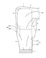
図9は、本発明の実施の形態3に係る滅菌ドレープの要部の構成および該要部を装着した医療用観察装置の構成を示す拡大斜視図である。同図に示す滅菌ドレープ8は、観察装置2を被覆するように被せられ、観察装置2の表面の滅菌状態を保持する。
(Embodiment 3)
FIG. 9 is an enlarged perspective view showing a configuration of a main part of a sterilized drape according to Embodiment 3 of the present invention and a configuration of a medical observation apparatus equipped with the main part. The sterilization drape 8 shown in the figure is covered so as to cover the observation device 2 and maintains the sterilized state of the surface of the observation device 2.
滅菌ドレープ8は、開口カバー81と、取付部82とを有する。開口カバー81の構成は、滅菌ドレープ1の開口カバー11の構成と同じである。また、滅菌ドレープ8の本体は、実施の形態1の滅菌ドレープ1の本体と同様の材料を用いて構成される。
The sterilized drape 8 has an
取付部82は、筒状部61より若干径が小さい円筒状をなす。取付部82は、筒状部61を周回した態様で筒状部61に固定して取り付けられる。取付部82は、実施の形態1の取付部12と同様の弾性部材を用いて構成され、外部から接触する物体の滑りを防止する機能を有する。
The
取付部82を筒状部61へ取り付ける際には、取付部82を伸ばして筒状部61の先端側から筒状部61を挿通する。その後、開口カバー81を顕微鏡部6の先端に取り付けることにより、滅菌ドレープ8の顕微鏡部6への装着が完了する。
When attaching the
以上説明した本発明の実施の形態3によれば、実施の形態1と同様の効果を得ることができる。加えて、本実施の形態3によれば、取付部82が円筒状の弾性部材からなるため、顕微鏡部6への装着が容易である。また、取付部82は、顕微鏡部6を周回する態様で顕微鏡部6に装着されるため、ユーザはより確実に顕微鏡部6を把持することができ、顕微鏡部6を思い通りに操作することができる。
According to the third embodiment of the present invention described above, the same effect as in the first embodiment can be obtained. In addition, according to the third embodiment, since the
なお、本実施の形態3において、変倍スイッチ64および焦点距離変更スイッチ65等、筒状部61に設けられる他のスイッチに対して入力部カバーを設けてもよい。さらに、筒状部61の断面が円形状ではなく、一部を異形状としたり、筒状部61の外周に部分的に凸部を設けたりすることで、取付部82が筒状部61に対して回転してしまうのをより抑えることができるとともに、取付部82を筒状部61に装着する際の位置決めが容易となる。
In the third embodiment, an input unit cover may be provided for other switches provided in the
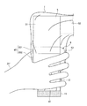
図10は、本実施の形態3の変形例に係る滅菌ドレープの要部の構成および該要部を装着した医療用観察装置の構成を示す拡大斜視図である。同図に示す滅菌ドレープ9は、開口カバー91と、取付部92とを有する。取付部92は、取付部82と同様、筒状部61より若干径が小さい円筒状をなし、取付部82と同様の材料からなる。なお、開口カバー91の構成は、滅菌ドレープ1の開口カバー11の構成と同じである。
FIG. 10 is an enlarged perspective view showing a configuration of a main part of a sterilized drape according to a modification of the third embodiment and a configuration of a medical observation apparatus equipped with the main part. The sterilizing drape 9 shown in the figure has an
取付部92には、開口カバー91と対向する端部と異なる端部から円筒の高さ方向へ向けて途中まで切り込まれたT字状のスリット921が形成されている。
The
取付部92を顕微鏡部6へ取り付ける際には、取付部92を径方向へ伸ばしてスリット921を開いた状態で筒状部61の先端側から筒状部61を挿通する。その後、開口カバー91を顕微鏡部6の先端に取り付けることにより、滅菌ドレープ9の顕微鏡部6への装着が完了する。
When attaching the
本変形例によれば、取付部92にスリット921を形成したことにより、取付部92を筒状部61に取り付ける際、取付部92の径を広げて装着できるので、一段と取り付けが容易となる。
According to this modification, since the
なお、スリット921の個数は2つ以上であってもよい。また、スリットの形状は、上述しT字状に限られるわけではなく、適宜変更可能である。また、取付部92を筒状部61に取り付けた後、スリット921の口元が開かないようにその口元を固定する固定部材を設けるようにすれば、取付部92を筒状部61に対してより確実に固定することができる。
The number of
(実施の形態4)
図11は、本発明の実施の形態4に係る滅菌ドレープの要部の構成および該要部を装着した医療用観察装置の構成を示す拡大斜視図である。同図に示す滅菌ドレープ10は、観察装置2を被覆するように被せられ、観察装置2の表面の滅菌状態を保持する。
(Embodiment 4)
FIG. 11 is an enlarged perspective view showing a configuration of a main part of a sterilized drape according to Embodiment 4 of the present invention and a configuration of a medical observation apparatus equipped with the main part. The
滅菌ドレープ10は、開口カバー101と、取付部102とを有する。開口カバー101の構成は、滅菌ドレープ1の開口カバー11の構成と同じである。また、滅菌ドレープ10の本体は、実施の形態1の滅菌ドレープ1と同様の材料を用いて構成される。
The sterilized
取付部102は帯状をなし、帯長さ方向(顕微鏡部6に取り付けた状態で顕微鏡部6を周回する方向に対応)の両端部に、例えば面ファスナーからなり、互いに他方と係合可能な係合部103、104を有する。取付部102の帯長さ方向の中央部105は、帯幅方向(顕微鏡部6に取り付けた状態における顕微鏡部6の高さ方向に対応)に沿って滅菌ドレープ10の袋状をなす本体の外表面側に接着されている。取付部102の帯長さは、係合部103、104の係合によって重なる部分を除いて、筒状部61の外周の長さより若干小さい。
The
図11に示す状態から滅菌ドレープ10を筒状部61に対して取り付ける際には、取付部102の両端を筒状部61に巻き付けて係合部103、104を互いに係合することによって筒状部61に対して固定する。
When the
取付部102は、実施の形態1の取付部12と同様の弾性部材を用いて構成され、外部から接触する物体の滑りを防止する機能を有する。
The
以上説明した本発明の実施の形態4によれば、実施の形態1と同様の効果を得ることができる。加えて、本実施の形態4によれば、取付部102の顕微鏡部6への取付が容易である。また、取付部102は、顕微鏡部6を周回しているため、ユーザは、より確実に顕微鏡部6を把持し、顕微鏡部6を思い通りに操作することができる。
According to the fourth embodiment of the present invention described above, the same effect as in the first embodiment can be obtained. In addition, according to the fourth embodiment, the
さらに、本実施の形態4によれば、取付部102は、顕微鏡部6へ取り付ける前の状態で薄い帯状をなしているため、かさばらず、変形により顕微鏡部6への取付が困難になるなどの不具合も起こりえない。したがって、滅菌ドレープ10は、出荷する際に梱包しやすい上、梱包材への収納効率にも優れており、安価で経済的である。
Furthermore, according to the fourth embodiment, the
なお、本実施の形態4において、筒状部61の断面が円形状ではなく、一部を異形状としたり、筒状部61の外周に部分的に凸部を設けたりすることで、取付部102が筒状部61に対して回転してしまうのをより抑えることができるとともに、取付部102を筒状部61に装着する際の位置決めが容易となる。このように筒状部61の形状が異形状であっても、取付部102を筒状部61に巻き付けて装着するため、取付部102を筒状部61に対して容易にフィットさせることができる。
Incidentally, in the fourth embodiment, since the cross section of the
(実施の形態5)
図12は、本発明の実施の形態5に係る滅菌ドレープの要部の構成および該要部を装着した医療用観察装置の構成を示す拡大斜視図である。図13は、本実施の形態5に係る滅菌ドレープの要部を図12と異なる方向から見た図である。図12および図13に示す滅菌ドレープ13は、観察装置2を被覆するように被せられ、観察装置2の表面の滅菌状態を保持する。滅菌ドレープ13の本体は、実施の形態1の滅菌ドレープ1と同様の材料を用いて構成される。
(Embodiment 5)
FIG. 12 is an enlarged perspective view showing the configuration of the main part of a sterilized drape according to
滅菌ドレープ13は、顕微鏡部6の先端に固定して取り付けられ、筒状部61に対する滑りを防止する機能を有する取付部131を有する。取付部131は、顕微鏡部6の外径より小さい径の円筒状をなす弾性部材からなる筒状部132と、筒状部132の高さ方向の端部であって顕微鏡部6の先端に対応する端部に設けられ、顕微鏡部6が被観察体からの光を集光する開口面を保護するカバーガラス133とを有する。取付部131は、実施の形態1の取付部12と同様の弾性部材を用いて構成され、外部から接触する物体の滑りを防止する機能を有する。
The sterilized
取付部131を顕微鏡部6へ取り付ける際には、取付部131の端部のうちカバーガラス133が設けられていない方の端部を径方向に伸ばして筒状部61の先端側から筒状部61を挿通する。その後、カバーガラス133の位置を顕微鏡部6の先端に位置合わせして装着することにより、滅菌ドレープ13の顕微鏡部6への装着が完了する。
When attaching the
以上説明した本発明の実施の形態5によれば、実施の形態1と同様の効果を得ることができる。加えて、本実施の形態5によれば、取付部131が開口カバーの機能も有しているため、取付部とは別に開口カバーを顕微鏡部6へ装着する手間を省くことができる。
According to the fifth embodiment of the present invention described above, the same effect as in the first embodiment can be obtained. In addition, according to the fifth embodiment, since the
なお、取付部131に対して、実施の形態3の変形例で説明したT字状のスリット921(図10を参照)と同様のスリットを形成することも可能である。
Note that a slit similar to the T-shaped slit 921 (see FIG. 10) described in the modification of the third embodiment can be formed in the
図14は、本実施の形態5の変形例に係る滅菌ドレープの要部の構成および該要部を装着した医療用観察装置の構成を示す拡大斜視図である。図15は、本変形例に係る滅菌ドレープの要部を図14と異なる方向から見た図である。図14および図15に示す滅菌ドレープ14は、顕微鏡部6の先端に装着される取付部141を有する。
FIG. 14 is an enlarged perspective view showing a configuration of a main part of a sterilized drape according to a modification of the fifth embodiment and a configuration of a medical observation apparatus equipped with the main part. FIG. 15 is a view of the main part of the sterilized drape according to the present modification viewed from a direction different from FIG. The sterilized
取付部141は、顕微鏡部6の外径より小さい径の円筒状をなす弾性部材からなる筒状部142と、筒状部142の高さ方向の端部であって顕微鏡部6の先端に対応する端部に設けられ、顕微鏡部6の開口面を保護するカバーガラス143とを有する。
The
筒状部142は、カバーガラス143の外周部分に、径方向に突出したフランジ部142aを有する。筒状部142は、実施の形態1の取付部12と同様の弾性部材を用いて構成され、外部から接触する物体の滑りを防止する機能を有する。
The
本変形例によれば、フランジ部142aが形成されているため、顕微鏡部6を把持する際に、誤って開口カバーに触れてしまい、開口カバーを汚してしまったり、照明光や観察光の光路を遮ってしまったりすることがない。また、本変形例によれば、顕微鏡部6の把持部分を物理的に制限できるため、ユーザは常に同じ感覚で顕微鏡部6を把持することができ、顕微鏡部6の操作を安定して行うことができる。
According to this modification, since the
(その他の実施の形態)
ここまで、本発明を実施するための形態を説明してきたが、本発明は、上述した実施の形態1〜5によってのみ限定されるべきものではない。例えば、滅菌ドレープの本体に、伸縮自在なリング形状をなす弛み防止部材を適宜配置してもよい。このような弛み防止部材の構成として、例えば図9に示す取付部82、図10に示す取付部92、または図11に示す取付部102と同様の構成を適用することも可能である。
(Other embodiments)
Up to this point, the mode for carrying out the present invention has been described. However, the present invention should not be limited only by the above-described first to fifth embodiments. For example, a loosening prevention member having a ring shape that can be expanded and contracted may be appropriately disposed in the body of the sterilized drape. As a configuration of such a slack preventing member, for example, a configuration similar to the mounting
弛み防止部材は、支持部5の動きによって滅菌ドレープに弛みが生じやすい箇所に設けるのが好ましい。このような場所として、例えば支持部5が有する関節部の近くを挙げることができる。
The loosening prevention member is preferably provided at a location where the sterilization drape is likely to loosen due to the movement of the
また、従来の手術用顕微鏡のように、鏡筒とは別の場所に各種スイッチが形成されたグリップ部を有する場合であっても、本発明を適用することが可能である。 Further, the present invention can be applied even when a grip portion in which various switches are formed in a place different from the lens barrel as in a conventional surgical microscope.
このように、本発明は、特許請求の範囲に記載した技術的思想を逸脱しない範囲内において、さまざまな実施の形態等を含み得るものである。 As described above, the present invention can include various embodiments and the like without departing from the technical idea described in the claims.
1、7、8、9、10、13、14 滅菌ドレープ
2 医療用観察装置
3 表示装置
4 ベース部
5 支持部
6 顕微鏡部
11、71、81、91、101 開口カバー
12、72、82、92、102、131、141 取付部
51 第1関節部
52 第1アーム部
53 第2関節部
54 第2アーム部
61 筒状部
62 撮像部
63 アーム操作スイッチ
64 変倍スイッチ
65 焦点距離変更スイッチ
121、122、721、722 突起部
121a、122a 取付凹部
132、142 筒状部
133、143 カバーガラス
142a フランジ部
611、612 取付凸部
621 光学系
622 撮像素子
641 ズームインスイッチ
642 ズームアウトスイッチ
651 遠景フォーカススイッチ
652 近景フォーカススイッチ
921 スリット
DESCRIPTION OF
Claims (12)
袋状をなす本体と、
前記本体の外表面側に設けられ、前記医療用観察装置を被覆した状態で前記グリップ部の側面に固定して取り付けられる取付部と、を備え、
前記医療用観察装置は、前記顕微鏡部が前記グリップ部としての機能を有することを特徴とする滅菌ドレープ。 A microscope unit for enlarging and imaging a minute part of an object to be observed, an input unit for receiving an operation instruction input to the microscope unit, and at least a part of the input unit provided on the surface, and a cylindrical grip unit A sterilizing drape that maintains the sterilization state of the medical observation device by covering the medical observation device provided with the medical observation device,
A bag-shaped body,
An attachment portion that is provided on the outer surface side of the main body and is fixedly attached to a side surface of the grip portion in a state of covering the medical observation device ;
In the medical observation apparatus, the microscope section has a function as the grip section .
前記顕微鏡部の外径より小さい径の筒状をなす弾性部材からなる筒状部と、
前記筒状部の高さ方向の端部であって前記顕微鏡部の先端に対応する端部に設けられ、前記顕微鏡部が前記被観察体からの光を集光する開口面を保護するカバーガラスと、
を有することを特徴とする請求項1〜3のいずれか一項に記載の滅菌ドレープ。 The mounting portion is
A cylindrical portion made of an elastic member having a cylindrical shape with a diameter smaller than the outer diameter of the microscope portion;
A cover glass that is provided at the end of the cylindrical portion in the height direction and that corresponds to the tip of the microscope portion, and the microscope portion protects an opening surface that collects light from the object to be observed. When,
The sterilized drape according to any one of claims 1 to 3 , characterized by comprising:
前記顕微鏡部が柱状をなして前記グリップ部としての機能を有し、
2つのアーム部および該2つのアーム部の一方を他方に対して回動可能に連結する関節部からなる組を少なくとも一組有し、先端部で前記顕微鏡部を該顕微鏡部の高さ方向の軸のまわりに回動可能に支持する支持部と、
前記顕微鏡部の側面であって撮像信号に基づく画像の上方に対応する側面に設けられ、前記アーム部の回動を許容する操作入力を受け付けるアーム操作スイッチと、
を備え、
前記入力部は、前記アーム操作スイッチを含むことを特徴とする請求項1〜11のいずれか一項に記載の滅菌ドレープ。 The medical observation apparatus includes:
The microscope part has a columnar shape and functions as the grip part,
There are at least one set of two arm portions and a joint portion that rotatably connects one of the two arm portions with respect to the other, and the microscope portion is arranged at the tip portion in the height direction of the microscope portion. A support portion that is pivotally supported about an axis;
An arm operation switch that is provided on a side surface of the microscope unit and corresponding to an upper side of an image based on an imaging signal, and that receives an operation input that allows rotation of the arm unit;
With
The sterilizing drape according to any one of claims 1 to 11, wherein the input unit includes the arm operation switch.
Priority Applications (4)
| Application Number | Priority Date | Filing Date | Title |
|---|---|---|---|
| JP2014127685A JP6367018B2 (en) | 2014-06-20 | 2014-06-20 | Sterile drape |
| US14/732,137 US10085803B2 (en) | 2014-06-20 | 2015-06-05 | Sterile drape |
| EP15170839.3A EP2957250B1 (en) | 2014-06-20 | 2015-06-05 | Sterile drape |
| US16/122,316 US10888390B2 (en) | 2014-06-20 | 2018-09-05 | Sterile drape |
Applications Claiming Priority (1)
| Application Number | Priority Date | Filing Date | Title |
|---|---|---|---|
| JP2014127685A JP6367018B2 (en) | 2014-06-20 | 2014-06-20 | Sterile drape |
Publications (3)
| Publication Number | Publication Date |
|---|---|
| JP2016007233A JP2016007233A (en) | 2016-01-18 |
| JP2016007233A5 JP2016007233A5 (en) | 2017-07-13 |
| JP6367018B2 true JP6367018B2 (en) | 2018-08-01 |
Family
ID=53385513
Family Applications (1)
| Application Number | Title | Priority Date | Filing Date |
|---|---|---|---|
| JP2014127685A Active JP6367018B2 (en) | 2014-06-20 | 2014-06-20 | Sterile drape |
Country Status (3)
| Country | Link |
|---|---|
| US (2) | US10085803B2 (en) |
| EP (1) | EP2957250B1 (en) |
| JP (1) | JP6367018B2 (en) |
Families Citing this family (18)
| Publication number | Priority date | Publication date | Assignee | Title |
|---|---|---|---|---|
| JP6367018B2 (en) * | 2014-06-20 | 2018-08-01 | ソニー・オリンパスメディカルソリューションズ株式会社 | Sterile drape |
| JP6456635B2 (en) * | 2014-09-16 | 2019-01-23 | ソニー・オリンパスメディカルソリューションズ株式会社 | Medical observation apparatus and medical observation system |
| US10736707B2 (en) | 2016-02-26 | 2020-08-11 | Covidien Lp | Drape management assemblies for robotic surgical systems |
| KR102476150B1 (en) * | 2016-06-30 | 2022-12-12 | 인튜어티브 서지컬 오퍼레이션즈 인코포레이티드 | Systems and methods of steerable elongated devices |
| US20190290378A1 (en) * | 2016-10-28 | 2019-09-26 | Naviswiss Ag | Sterile covering for an optical device |
| JP7098312B2 (en) * | 2017-02-03 | 2022-07-11 | ソニー・オリンパスメディカルソリューションズ株式会社 | Protective cover and medical observation device |
| JP2018166639A (en) * | 2017-03-29 | 2018-11-01 | ソニー・オリンパスメディカルソリューションズ株式会社 | Drape, surgical microscope, and surgical microscope system |
| JP6869787B2 (en) | 2017-04-13 | 2021-05-12 | ソニー・オリンパスメディカルソリューションズ株式会社 | Medical observation device and status notification method |
| JP6904762B2 (en) * | 2017-04-13 | 2021-07-21 | ソニー・オリンパスメディカルソリューションズ株式会社 | Medical sterilization cover and medical observation device |
| USD877226S1 (en) | 2017-04-28 | 2020-03-03 | Ecolab Usa Inc. | Optical lens housing |
| USD875151S1 (en) | 2017-04-28 | 2020-02-11 | Ecolab Usa Inc. | Microscope drape |
| US10512515B2 (en) | 2017-07-31 | 2019-12-24 | Intuitive Surgical Operations, Inc. | Systems and methods for steerable elongate device |
| US11096754B2 (en) | 2017-10-04 | 2021-08-24 | Mako Surgical Corp. | Sterile drape assembly for surgical robot |
| EP3698748B1 (en) * | 2019-02-25 | 2023-11-15 | Baxter Medical Systems GmbH + Co. KG | Surgical table disposable base cover |
| US11375965B2 (en) * | 2019-11-01 | 2022-07-05 | Turner Imaging Systems, Inc. | Sterile barriers for medical devices |
| IT202000002545A1 (en) | 2020-02-10 | 2021-08-10 | Medical Microinstruments Spa | ASSEMBLY OF STERILE BARRIER AND ROBOTIC SURGERY SYSTEM |
| CA3166575A1 (en) | 2020-02-10 | 2021-08-19 | Massimiliano Simi | Sterile barrier assembly and robotic surgery system |
| IT202000002539A1 (en) | 2020-02-10 | 2021-08-10 | Medical Microinstruments Spa | ASSEMBLY OF CONTROL HANDPIECE AND ROBOTIC SURGERY SYSTEM |
Family Cites Families (12)
| Publication number | Priority date | Publication date | Assignee | Title |
|---|---|---|---|---|
| US3528720A (en) * | 1968-12-18 | 1970-09-15 | Richards Mfg Co | Operating microscope envelope means |
| US3698791A (en) | 1971-04-19 | 1972-10-17 | Xerox Corp | Drape for operating microscope |
| US4799779A (en) * | 1988-03-22 | 1989-01-24 | Mesmer Jeffrey C | Microscope drape |
| JP2726346B2 (en) * | 1991-12-25 | 1998-03-11 | 佐原 今朝徳 | Automatic focusing mechanism of surgical microscope |
| JP3704381B2 (en) * | 1994-11-15 | 2005-10-12 | オリンパス株式会社 | Sterile drape of surgical microscope |
| US5803905A (en) * | 1996-03-28 | 1998-09-08 | Ajor Medical Technologies, L.L.C. | Surgical camera and light assembly allowing adjustable focus and zoom capability and method of use |
| US5873814A (en) | 1996-07-12 | 1999-02-23 | Adair; Edwin L. | Sterile encapsulated endoscopic video monitor and method |
| JP3899164B2 (en) * | 1996-07-26 | 2007-03-28 | オリンパス株式会社 | Surgical microscope |
| US20080144178A1 (en) * | 2006-12-13 | 2008-06-19 | Microtek Medical, Inc. | Microscope drape lens cover system and assembly method |
| JP5818723B2 (en) * | 2011-03-17 | 2015-11-18 | 株式会社トーカイ | Surgical drape |
| JP5827547B2 (en) * | 2011-11-16 | 2015-12-02 | 株式会社リブドゥコーポレーション | Drape and disposable medical equipment set |
| JP6367018B2 (en) * | 2014-06-20 | 2018-08-01 | ソニー・オリンパスメディカルソリューションズ株式会社 | Sterile drape |
-
2014
- 2014-06-20 JP JP2014127685A patent/JP6367018B2/en active Active
-
2015
- 2015-06-05 EP EP15170839.3A patent/EP2957250B1/en active Active
- 2015-06-05 US US14/732,137 patent/US10085803B2/en not_active Expired - Fee Related
-
2018
- 2018-09-05 US US16/122,316 patent/US10888390B2/en active Active
Also Published As
| Publication number | Publication date |
|---|---|
| EP2957250B1 (en) | 2020-11-18 |
| US20190069969A1 (en) | 2019-03-07 |
| US10085803B2 (en) | 2018-10-02 |
| EP2957250A1 (en) | 2015-12-23 |
| JP2016007233A (en) | 2016-01-18 |
| US20150366618A1 (en) | 2015-12-24 |
| US10888390B2 (en) | 2021-01-12 |
Similar Documents
| Publication | Publication Date | Title |
|---|---|---|
| JP6367018B2 (en) | Sterile drape | |
| JP6367019B2 (en) | Sterile drape | |
| AU2004264876B2 (en) | Otoscopic tip element and related method of use | |
| JP5006478B2 (en) | Endoscope | |
| US5528432A (en) | Intra-oral optical viewing device | |
| AU2018259192B2 (en) | New product | |
| NZ544954A (en) | Otoscope | |
| US10610321B2 (en) | Drape, surgical microscope, and surgical microscope system | |
| JP2022514323A (en) | Ear visualization and treatment system | |
| JP6612226B2 (en) | Medical observation apparatus and medical observation system | |
| JP5996359B2 (en) | Medical observation system | |
| JP2014033716A (en) | Endoscope, endoscope apparatus, and endoscope system | |
| JP6760622B2 (en) | Endoscope device | |
| JPH11113841A (en) | Otorhinological videoscope and otorhinological videoscope system using it | |
| JP4847071B2 (en) | Endoscopic imaging device | |
| JP7264162B2 (en) | Interchangeable lens, imaging device and rotation detection device | |
| JP2013172843A (en) | Endoscope | |
| JP6856690B2 (en) | Medical observation device and medical observation system | |
| JP2010142268A (en) | Endoscope | |
| JPWO2015151778A1 (en) | In-body surveillance camera system and camera unit | |
| JP4668440B2 (en) | Electronic endoscope |
Legal Events
| Date | Code | Title | Description |
|---|---|---|---|
| A521 | Written amendment |
Free format text: JAPANESE INTERMEDIATE CODE: A523 Effective date: 20170529 |
|
| A621 | Written request for application examination |
Free format text: JAPANESE INTERMEDIATE CODE: A621 Effective date: 20170529 |
|
| A977 | Report on retrieval |
Free format text: JAPANESE INTERMEDIATE CODE: A971007 Effective date: 20180327 |
|
| A131 | Notification of reasons for refusal |
Free format text: JAPANESE INTERMEDIATE CODE: A131 Effective date: 20180403 |
|
| A521 | Written amendment |
Free format text: JAPANESE INTERMEDIATE CODE: A523 Effective date: 20180530 |
|
| TRDD | Decision of grant or rejection written | ||
| A01 | Written decision to grant a patent or to grant a registration (utility model) |
Free format text: JAPANESE INTERMEDIATE CODE: A01 Effective date: 20180612 |
|
| A61 | First payment of annual fees (during grant procedure) |
Free format text: JAPANESE INTERMEDIATE CODE: A61 Effective date: 20180704 |
|
| R150 | Certificate of patent or registration of utility model |
Ref document number: 6367018 Country of ref document: JP Free format text: JAPANESE INTERMEDIATE CODE: R150 |