JP6298362B2 - Imaging apparatus, control method therefor, and imaging system - Google Patents
Imaging apparatus, control method therefor, and imaging system Download PDFInfo
- Publication number
- JP6298362B2 JP6298362B2 JP2014114371A JP2014114371A JP6298362B2 JP 6298362 B2 JP6298362 B2 JP 6298362B2 JP 2014114371 A JP2014114371 A JP 2014114371A JP 2014114371 A JP2014114371 A JP 2014114371A JP 6298362 B2 JP6298362 B2 JP 6298362B2
- Authority
- JP
- Japan
- Prior art keywords
- focus detection
- imaging
- correction
- information
- evaluation value
- Prior art date
- Legal status (The legal status is an assumption and is not a legal conclusion. Google has not performed a legal analysis and makes no representation as to the accuracy of the status listed.)
- Active
Links
Images


Classifications
-
- H—ELECTRICITY
- H04—ELECTRIC COMMUNICATION TECHNIQUE
- H04N—PICTORIAL COMMUNICATION, e.g. TELEVISION
- H04N23/00—Cameras or camera modules comprising electronic image sensors; Control thereof
- H04N23/60—Control of cameras or camera modules
- H04N23/67—Focus control based on electronic image sensor signals
- H04N23/672—Focus control based on electronic image sensor signals based on the phase difference signals
-
- H—ELECTRICITY
- H04—ELECTRIC COMMUNICATION TECHNIQUE
- H04N—PICTORIAL COMMUNICATION, e.g. TELEVISION
- H04N1/00—Scanning, transmission or reproduction of documents or the like, e.g. facsimile transmission; Details thereof
- H04N1/21—Intermediate information storage
- H04N1/2104—Intermediate information storage for one or a few pictures
- H04N1/2112—Intermediate information storage for one or a few pictures using still video cameras
-
- H—ELECTRICITY
- H04—ELECTRIC COMMUNICATION TECHNIQUE
- H04N—PICTORIAL COMMUNICATION, e.g. TELEVISION
- H04N23/00—Cameras or camera modules comprising electronic image sensors; Control thereof
- H04N23/60—Control of cameras or camera modules
- H04N23/67—Focus control based on electronic image sensor signals
- H04N23/673—Focus control based on electronic image sensor signals based on contrast or high frequency components of image signals, e.g. hill climbing method
-
- H—ELECTRICITY
- H04—ELECTRIC COMMUNICATION TECHNIQUE
- H04N—PICTORIAL COMMUNICATION, e.g. TELEVISION
- H04N25/00—Circuitry of solid-state image sensors [SSIS]; Control thereof
- H04N25/70—SSIS architectures; Circuits associated therewith
- H04N25/703—SSIS architectures incorporating pixels for producing signals other than image signals
- H04N25/704—Pixels specially adapted for focusing, e.g. phase difference pixel sets
Description
本発明は、撮像装置及びその制御方法、及び撮像システムに関し、更に詳しくは、自動焦点調節機能を有する撮像装置及びその制御方法、及び撮像システムに関するものである。 The present invention relates to an imaging apparatus, a control method thereof, and an imaging system, and more particularly to an imaging apparatus having an automatic focus adjustment function, a control method thereof, and an imaging system.
撮像装置の焦点調節方法の一般的な方式として、コントラストAF方式と位相差AF方式とがある。コントラストAF方式も位相差AF方式もビデオカメラやデジタルスチルカメラで多く用いられるAF方式であり、撮像素子が焦点検出用センサとして用いられるものが存在する。これらの焦点調節方法は、光学系の諸収差の影響で焦点検出結果に誤差を含む場合があり、その誤差を低減するための方法が、種々提案されている。 There are a contrast AF method and a phase difference AF method as a general method for adjusting the focus of the imaging apparatus. Both the contrast AF method and the phase difference AF method are AF methods that are often used in video cameras and digital still cameras, and there are devices in which an image sensor is used as a focus detection sensor. These focus adjustment methods may include an error in the focus detection result due to the influence of various aberrations of the optical system, and various methods for reducing the error have been proposed.
例えば、特許文献1には、焦点検出を行うために用いる信号の評価周波数(評価帯域)によって、焦点検出結果を補正する補正値を算出する方法が開示されている。このような焦点検出誤差は、上述の焦点調節方法によらず、コントラストAF方式や位相差AF方式に用いられる焦点調節用信号の評価帯域などによって発生する。 For example, Patent Document 1 discloses a method of calculating a correction value for correcting a focus detection result based on an evaluation frequency (evaluation band) of a signal used for focus detection. Such a focus detection error is caused by an evaluation band of a focus adjustment signal used in the contrast AF method or the phase difference AF method, regardless of the focus adjustment method described above.
しかしながら、特許文献1に記載された構成では、焦点検出を行うために用いる信号の種類が増えるほど、必要な補正値も多くなる。そのため、補正値を記憶するために必要なメモリ容量が増えることにつながり、コストアップにつながる。特に焦点検出機能を有するカメラに対して、撮影レンズが交換可能な撮像装置の場合には、焦点検出機能の違いや焦点検出方法の違いに対応した補正値を撮影レンズが記憶することが必要となるため、メモリ容量の増大は、撮影レンズのコストアップにつながる。 However, in the configuration described in Patent Document 1, the required correction value increases as the types of signals used for focus detection increase. For this reason, the memory capacity necessary for storing the correction value increases, leading to an increase in cost. In particular, in the case of an imaging apparatus in which the photographic lens can be exchanged for a camera having a focus detection function, it is necessary for the photographic lens to store correction values corresponding to differences in focus detection function and focus detection methods. Therefore, an increase in memory capacity leads to an increase in the cost of the photographing lens.
本発明は上記問題点を鑑みてなされたものであり、撮像装置において、焦点検出結果を補正する精度を損なうことなく、補正値を記憶するための容量の増大を防ぐことを目的とする。 The present invention has been made in view of the above problems, and an object of the present invention is to prevent an increase in capacity for storing correction values without impairing the accuracy of correcting a focus detection result in an imaging apparatus.
上記目的を達成するために、本発明の撮像装置は、撮像素子から出力された信号に基づいて、複数の異なる焦点検出方法のいずれかを用いて、撮影光学系を合焦状態に制御するための評価値を検出する焦点検出手段と、前記評価値を、検出に用いられた焦点検出方法に応じて補正する補正手段と、前記複数の異なる焦点検出方法のうち、予め決められた焦点検出方法を用いて検出された評価値を補正するための基準補正値を算出するための情報と、前記予め決められた焦点検出方法を除く焦点検出方法を用いて検出された評価値を補正するための補正値を、前記基準補正値から算出するための情報とを記憶した記憶手段とを有し、前記補正手段は、前記記憶手段に記憶された情報を用いて、前記評価値を補正するための補正値を算出して、前記補正を行う。 In order to achieve the above object, an imaging apparatus according to the present invention controls an imaging optical system in a focused state using one of a plurality of different focus detection methods based on a signal output from an imaging element. Focus detection means for detecting the evaluation value, correction means for correcting the evaluation value according to the focus detection method used for detection, and a predetermined focus detection method among the plurality of different focus detection methods Information for calculating a reference correction value for correcting an evaluation value detected using the method, and an evaluation value detected using a focus detection method excluding the predetermined focus detection method Storage means storing information for calculating a correction value from the reference correction value, and the correction means corrects the evaluation value using the information stored in the storage means. Calculate the correction value Make a correction.
本発明によれば、撮像装置において、焦点検出結果を補正する精度を損なうことなく、補正値を記憶するための容量の増大を防ぐことができる。 According to the present invention, an increase in capacity for storing a correction value can be prevented without impairing the accuracy of correcting the focus detection result in the imaging apparatus.
以下、添付図面を参照して本発明を実施するための形態を詳細に説明する。 DESCRIPTION OF EMBODIMENTS Hereinafter, embodiments for carrying out the present invention will be described in detail with reference to the accompanying drawings.
<第1の実施形態>
第1の実施形態では、本発明をレンズ交換可能な一眼レフタイプのデジタルカメラに適用した例について説明する。
<First Embodiment>
In the first embodiment, an example in which the present invention is applied to a single-lens reflex digital camera with interchangeable lenses will be described.
●撮像装置の構成の説明
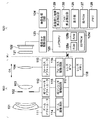
図1は、第1の実施形態におけるデジタルカメラの概略構成を示すブロック図である。上述したように、第1の実施形態におけるデジタルカメラは交換レンズ式一眼レフカメラであり、レンズユニット100とカメラ本体120とを有する。レンズユニット100は図中央の点線で示されるマウントMを介して、カメラ本体120と接続される。
Description of Configuration of Imaging Device FIG. 1 is a block diagram illustrating a schematic configuration of a digital camera according to the first embodiment. As described above, the digital camera according to the first embodiment is an interchangeable lens single-lens reflex camera, and includes the
レンズユニット100は、第1レンズ群101、絞り兼用シャッタ102、第2レンズ群103、フォーカスレンズ群(以下、単に「フォーカスレンズ」と呼ぶ。)104、及び、駆動/制御系を有する。このようにレンズユニット100は、フォーカスレンズ104を含むと共に被写体の像を形成する撮影レンズを有する。
The
第1レンズ群101は、レンズユニット100の先端に配置され、光軸方向OAに進退可能に保持される。絞り兼用シャッタ102は、その開口径を調節することで撮影時の光量調節を行う他、静止画撮影時には露光秒時調節用シャッタとして機能する。絞り兼用シャッタ102及び第2レンズ群103は一体として光軸方向OAに進退し、第1レンズ群101の進退動作との連動によりズーム機能を実現する。また、フォーカスレンズ104を光軸方向OAに進退させることで焦点調節が行われる。
The
駆動/制御系は、ズームアクチュエータ111、絞りシャッタアクチュエータ112、フォーカスアクチュエータ113、ズーム駆動回路114、絞りシャッタ駆動回路115、フォーカス駆動回路116、レンズMPU117、レンズメモリ118を有する。
The drive / control system includes a
ズーム駆動回路114は、撮影者のズーム操作に応じてズームアクチュエータ111を駆動して、第1レンズ群101や第2レンズ群103を光軸方向OAに進退駆動させることで、ズーム操作を行う。シャッタ駆動回路115は、絞りシャッタアクチュエータ112を駆動制御して絞り兼用シャッタ102の開口径を制御して、撮影光量を調節すると共に、静止画撮影時の露光時間制御を行う。フォーカス駆動回路116は、焦点検出結果に基づいてフォーカスアクチュエータ113を駆動制御して、フォーカスレンズ104を光軸方向OAに進退駆動させることで、焦点調節を行う。また、フォーカスアクチュエータ113には、フォーカスレンズ104の現在位置を検出する位置検出部としての機能が備わっている。
The
レンズMPU117は、レンズユニット100に係る全ての演算、制御を行い、ズーム駆動回路114、絞りシャッタ駆動回路115、フォーカス駆動回路116、レンズメモリ118を制御する。また、レンズMPU117は、現在のレンズ位置を検出し、カメラMPU125からの要求に対してレンズ位置情報を通知する。このレンズ位置情報は、フォーカスレンズ104の光軸上位置、撮影光学系が移動していない状態の射出瞳の光軸上位置、直径、射出瞳の光束を制限するレンズ枠の光軸上位置、直径などの情報を含む。レンズメモリ118には自動焦点調節に必要な光学情報を記憶する。
The lens MPU 117 performs all calculations and control related to the
一方、カメラ本体120は、光学的ローパスフィルタ(LPF)121、撮像素子122、駆動/制御系を有する。光学的LPF121と撮像素子122はレンズユニット100からの光束によって被写体像を形成する撮像光学系として機能する。また、第1レンズ群101、絞り兼用シャッタ102、第2レンズ群103、フォーカスレンズ104、光学的LPF121は、上述した撮影光学系を構成している。
On the other hand, the
光学的LPF121は、撮影画像の偽色やモアレを軽減する。撮像素子122はCMOSセンサとその周辺回路で構成され、横方向にm画素、縦方向にn画素が配置される。撮像素子122は、図2を参照して後述するような構成の光電変換素子を有する画素を含んでおり、後述する位相差方式の焦点検出(位相差AF)を行うための一対の信号を出力することができる。得られた画像データの内、位相差AFに対応する画像データは、画像処理回路124で焦点検出用画像データに変換される。一方で、得られた画像データの内、表示や記録、コントラスト方式の焦点検出のために用いられる画像データも、画像処理回路124に送られ、目的に合わせた所定の処理が行われる。
The
駆動/制御系は、撮像素子駆動回路123、画像処理回路124、カメラMPU125、表示器126、操作スイッチ群127、メモリ128、撮像面位相差焦点検出部129、TVAF焦点検出部130を有する。
The drive / control system includes an image
撮像素子駆動回路123は、撮像素子122の動作を制御するとともに、取得した画像信号をA/D変換してカメラMPU125及び画像処理回路124に送信する。画像処理回路124は、撮像素子122が取得した画像信号のγ変換、カラー補間、JPEG圧縮などを行う。
The image
カメラMPU(プロセッサ)125は、カメラ本体120に係る全ての演算、制御を行い、撮像素子駆動回路123、画像処理回路124、表示器126、操作SW127、メモリ128、撮像面位相差焦点検出部129、TVAF焦点検出部130を制御する。また、カメラMPU125はマウントMの信号線を介してレンズMPU117と接続され、レンズMPU117に対してレンズ位置の取得や所定の駆動量でのレンズ駆動要求を発行したり、レンズユニット100に固有の光学情報を取得したりする。なお、カメラMPU125には、カメラ動作を制御するプログラムを格納したROM125a、変数を記憶するRAM125b、諸パラメータを記憶するEEPROM125cが内蔵されている。
The camera MPU (processor) 125 performs all calculations and controls related to the
表示器126はLCDなどから構成され、カメラの撮影モードに関する情報、撮影前のプレビュー画像と撮影後の確認用画像、焦点検出時の合焦状態表示画像などを表示する。操作スイッチ群127は、電源スイッチ、レリーズ(撮影トリガ)スイッチ、ズーム操作スイッチ、撮影モード選択スイッチ等で構成される。第1の実施形態におけるメモリ128は、フラッシュメモリ等の着脱可能なメモリで、撮影済み画像を記録する。
The
撮像面位相差焦点検出部129は、撮像素子122、画像処理回路124により得られる焦点検出用画像データの像信号により位相差方式の焦点検出処理(撮像面位相差AF)を行う。より具体的には、撮像面位相差焦点検出部129は、撮影光学系の一対の瞳領域を通過する光束により焦点検出用画素に形成される一対の像のずれ量に基づいて撮像面位相差AFを行う。撮像面位相差AFの方法については、後に詳細に説明する。
The imaging plane phase difference focus detection unit 129 performs a phase difference type focus detection process (imaging plane phase difference AF) based on the image signal of the focus detection image data obtained by the
TVAF焦点検出部130は、画像処理回路124にて得られた画像情報のコントラスト成分により各種TVAF用評価値を算出し、コントラスト方式の焦点検出処理(TVAF)を行う。コントラスト方式の焦点検出処理では、フォーカスレンズ104を移動しながら複数のフォーカスレンズ位置で焦点評価値を算出し、焦点評価値がピークとなるフォーカスレンズ位置を検出する。
The TVAF
このように、第1の実施形態は撮像面位相差AFとTVAFを組み合わせており、状況に応じて、選択的に使用したり、組み合わせて使用したりすることができる。カメラMPU125は、撮像面位相差AFとTVAF各々の焦点検出結果を用いて、フォーカスレンズ104の位置を制御する。
As described above, the first embodiment combines the imaging plane phase difference AF and the TVAF, and can be selectively used or used in combination depending on the situation. The
●焦点検出の説明
次に、撮像素子122の信号を用いた、デジタルカメラにおける焦点検出の詳細について説明する。第1の実施形態の焦点検出では撮像面位相差AFとTVAFを採用している。まず、それぞれのAF方式について説明する。
Explanation of focus detection Next, details of focus detection in a digital camera using signals from the
(撮像面位相差AFの説明)
最初に、図2から図4を用いて、撮像面位相差AFについて説明する。図2は第1の実施形態における撮像素子122の画素配列を模式的に示した図で、2次元CMOSエリアセンサの縦(Y方向)6行と横(X方向)8列の範囲を、レンズユニット100側から観察した状態を示している。カラーフィルタにはベイヤー配列が適用され、奇数行の画素211には、左から順に緑(Green)と赤(Red)のカラーフィルタが交互に設けられる。また、偶数行の画素211には、左から順に青(Blue)と緑(Green)のカラーフィルタが交互に設けられる。また、オンチップマイクロレンズ211iがカラーフィルタの上に構成されている。オンチップマイクロレンズ211iの内側に配置された複数の矩形は、それぞれ光電変換部211a、211bである。
(Description of imaging plane phase difference AF)
First, the imaging plane phase difference AF will be described with reference to FIGS. FIG. 2 is a diagram schematically showing the pixel arrangement of the
第1の実施形態では、すべての画素の光電変換部はX方向に2分割され、分割された一方の領域の光電変換信号と、2つの領域の光電変換信号の和をそれぞれ独立して読み出しできる構成となっている。そして、独立して読み出しされた信号は、2つの領域の光電変換信号の和と分割された一方の領域の光電変換信号との差分をとることにより、もう一方の光電変換領域で得られる信号に相当する信号を得ることができる。このように分割された領域の光電変換信号は、位相差検出用の信号として、後述する方法で位相差AFに用いられるほか、視差情報を有した複数画像から構成される立体(3D)画像を生成するために用いることもできる。一方で、2つの領域の光電変換信号の和は、通常の撮影画像として用いられる。 In the first embodiment, the photoelectric conversion units of all the pixels are divided into two in the X direction, and the sum of the photoelectric conversion signals of one divided region and the photoelectric conversion signals of the two regions can be read independently. It has a configuration. Then, the signal read out independently is converted into a signal obtained in the other photoelectric conversion region by taking the difference between the sum of the photoelectric conversion signals of the two regions and the photoelectric conversion signal of one of the divided regions. A corresponding signal can be obtained. The photoelectric conversion signal of the region thus divided is used as a phase difference detection signal for phase difference AF by a method described later, and a stereoscopic (3D) image composed of a plurality of images having parallax information is used. It can also be used to generate. On the other hand, the sum of the photoelectric conversion signals of the two regions is used as a normal captured image.
図3は、第1の実施形態における読み出し回路を含む撮像素子122の概略構成を示す図である。151は水平走査回路、153は垂直走査回路である。そして各画素の境界部には、垂直走査ライン152a及び152bと、水平走査ライン154a及び154bが配線され、各光電変換部211a、211bからはこれらの走査ラインを介して信号が外部に読み出される。
FIG. 3 is a diagram illustrating a schematic configuration of the
なお、第1の実施形態の撮像素子122は、解像度の異なる以下の2種類の読み出しモードで駆動可能とする。第1の読み出しモードは全画素読み出しモードと称するもので、高精細静止画を撮像するためのモードである。この場合は、全画素の信号が読み出される。
Note that the
第2の読み出しモードは間引き読み出しモードと称するもので、動画記録、もしくはプレビュー画像の表示のみを行うためのモードである。この場合に必要な画素数は全画素よりも少ないため、画素群はX方向及びY方向共に所定比率に間引いた画素からのみ信号を読み出す。また、高速に読み出す必要がある場合にも、同様に間引き読み出しモードを用いる。X方向に間引く際には、信号の加算を行ってS/Nの改善を図り、Y方向に対する間引きは、間引かれる行の信号出力を無視する。位相差方式、コントラスト方式の焦点検出も通常は、第2の読み出しモードで行われる。但し、より高精度に焦点検出を行いたい場合やライブビュー表示を拡大して表示する場合には、第1の読み出しモードで焦点検出を行ったり、ライブビュー表示を行ったりする。 The second readout mode is called a thinning readout mode, and is a mode for performing only moving image recording or preview image display. In this case, since the number of necessary pixels is smaller than that of all the pixels, the pixel group reads signals only from pixels thinned out at a predetermined ratio in both the X direction and the Y direction. Also, when it is necessary to read at high speed, the thinning-out reading mode is used in the same manner. When thinning out in the X direction, signal addition is performed to improve S / N, and thinning out in the Y direction ignores the signal output of the thinned out rows. Usually, phase detection and contrast focus detection are also performed in the second readout mode. However, when focus detection is to be performed with higher accuracy or when live view display is enlarged and displayed, focus detection is performed in the first readout mode or live view display is performed.
図4は、第1の実施形態の撮像装置において、撮影光学系の射出瞳面と、像高ゼロすなわち像面中央近傍に配置された画素211の光電変換部との共役関係を説明する図である。撮像素子122の画素211の光電変換部211a、211bと、撮影光学系の射出瞳面とは、オンチップマイクロレンズ211iによって共役関係となるように設計される。そして撮影光学系の射出瞳は、一般的に光量調節用の虹彩絞りが置かれる面とほぼ一致する。一方、第1の実施形態における撮影光学系は変倍機能を有したズームレンズであるが、光学タイプによっては変倍操作を行うと、射出瞳の像面からの距離や大きさが変化する。図4における撮影光学系は、焦点距離が広角端と望遠端の中間、すなわちMiddleの状態を示している。これを標準的な射出瞳距離Zepと仮定して、オンチップマイクロレンズの形状や、像高(X、Y座標)に応じた偏心パラメータの最適設計がなされる。
FIG. 4 is a diagram for explaining the conjugate relationship between the exit pupil plane of the imaging optical system and the photoelectric conversion unit of the
図4(a)において、鏡筒部材101bは第1レンズ群を保持し、鏡筒部材104bはフォーカスレンズ104を保持する。絞り102は、絞り開放時の開口径を規定する開口板102aと、絞り込み時の開口径を調節するための絞り羽根102bとを有する。なお、撮影光学系を通過する光束の制限部材として作用する鏡筒部材101b、開口板102a、絞り羽根102b、及び鏡筒部材104bは、像面から観察した場合の光学的な虚像を示している。また、絞り102の近傍における合成開口をレンズの射出瞳と定義し、前述したように像面からの距離をZepとしている。
In FIG. 4A, the
図4(a)では、被写体像を光電変換するための画素211は、像面中央近傍に配置されものを示しており、以下、中央画素と呼ぶ。中央画素211は、最下層より、光電変換部211a、211b、配線層211e〜211g、カラーフィルタ211h、及びオンチップマイクロレンズ211iの各部材で構成される。そして2つの光電変換部211a、211bはオンチップマイクロレンズ211iによって撮影光学系の射出瞳面に投影される。また別の言い方をすれば、撮影光学系の射出瞳が、オンチップマイクロレンズ211iを介して、光電変換部211a、211bの表面に投影されることになる。
In FIG. 4A, the
図4(b)は、撮影光学系の射出瞳面上における、光電変換部211a、211bの投影像を示したもので、光電変換部211a及び211bに対する投影像は各々EP1a及びEP1bとなる。また本第1の実施形態では、上述したように、撮像素子122は、2つの光電変換部211aと211bのいずれか一方の出力と、両方の和の出力を得ることができる。両方の和の出力は、撮影光学系のほぼ全瞳領域である投影像EP1a、EP1bの両方の領域を通過した光束を光電変換したものに対応する。
FIG. 4B shows projected images of the
図4(a)において、撮影光学系を通過する光束の最外部をLで示すように、光束は、絞りの開口板102aで規制されており、投影像EP1a及びEP1bは撮影光学系によるケラレがほぼ発生していない。また、図4(b)では、図4(a)の光束をTLで示している。円で示される光束TLの内側に、光電変換部211a、211bの投影像EP1a、EP1bの大部分が含まれていることからも、ケラレがほぼ発生していないことがわかる。光束は、絞りの開口板102aでのみ制限されているため、光束TLは、開口板102aの開口径とほぼ等しいと言える。この際、像面中央では各投影像EP1a及びEP1bのケラレ状態は光軸に対して対称となり、各光電変換部211a及び211bが受光する光量は等しい。
In FIG. 4A, the outermost portion of the light beam passing through the photographing optical system is indicated by L, and the light beam is regulated by the
このように、マイクロレンズ211iと、分割された光電変換部211a及び211bにより、レンズユニット100の射出光束が瞳分割される。そして、同一行上に配置された所定範囲内の複数の画素211において、光電変換部211aの出力をつなぎ合わせて編成したものをAF用A像、同じく光電変換部211bの出力をつなぎ合わせて編成したものをAF用B像とする。なお、AF用A像及びB像の信号としては、光電変換部211a、211bの、ベイヤー配列の緑、赤、青、緑の出力を加算し、疑似的に輝度(Y)信号として算出されたものを用いるものとする。但し、赤、青、緑の色毎に、AF用A像、B像を編成してもよい。このように生成したAF用A像とB像の相対的な像ずれ量を相関演算により検出することで、所定領域の焦点ずれ量、すなわちデフォーカス量を検出することができる。なお、第1の実施形態では、AF用A像もしくはB像のいずれか一方は撮像素子122からは出力されないが、上述した通り、A像出力とB像出力の和が出力されるため、その出力と他方の出力の差分から、もう一方の信号を得ることができる。
Thus, the exit light flux of the
以上図2〜図4を参照して説明した様に、撮像素子122は射出瞳を分割した光束を受光する画素を備えているため、得られた信号から位相差AFを行うことが可能である。
As described above with reference to FIGS. 2 to 4, since the
なお、上述の説明では、水平方向に射出瞳を分割する構成を説明したが、撮像素子122上に、垂直方向に射出瞳を分割する画素を合わせて設けてもよい。両方向に射出瞳を分割する画素を設けることにより、水平だけでなく、垂直方向の被写体のコントラストに対応した焦点検出を行うことができる。また、すべての画素の光電変換部を2分割するものとして説明したが、光電変換部を3分割以上してもよく、また、位相差AFのみのためだけであれば一部の画素の光電変換部を分割するように構成してもよい。
In the above description, the configuration in which the exit pupil is divided in the horizontal direction has been described. However, pixels that divide the exit pupil in the vertical direction may be provided on the
(TVAFの説明)
次に、TVAFのための各種AF用評価値の算出の流れについて説明する。図5は、TVAF焦点検出部130の構成を主に示すブロック図である。
(Description of TVAF)
Next, the flow of calculating various AF evaluation values for TVAF will be described. FIG. 5 is a block diagram mainly showing the configuration of the TVAF
撮像素子122から読み出された信号がTVAF焦点検出部130に入力されると、AF評価用信号処理回路401において、ベイヤー配列信号からの緑(G)信号の抽出と、低輝度成分を強調して高輝度成分を抑圧するガンマ補正処理が施される。第1の実施形態では、TVAFを緑(G)信号を用いて行う場合を説明するが、赤(R)、青(B)、緑(G)の全ての信号を用いてもよい。また、RGB全色用いて輝度(Y)信号を生成してもよい。従って、AF評価用信号処理回路401で生成される出力信号は、用いられた色によらず、以後の説明では、輝度信号Yと呼ぶこととする。
When the signal read from the
次に、Yピーク評価値の算出方法について説明する。AF評価用信号処理回路401によってガンマ補正された輝度信号Yは、水平ライン毎のラインピーク値を検出するためのラインピーク検出回路402へ入力される。この回路によって、領域設定回路413によって設定された各焦点検出領域内で水平ライン毎のYラインピーク値が求められる。更に、ラインピーク検出回路402の出力は垂直ピーク検出回路405に入力される。この回路によって、領域設定回路413によって設定された各焦点検出領域内で垂直方向にピークホールドが行われ、Yピーク評価値が生成される。Yピーク評価値は、高輝度被写体や低照度被写体の判定に有効である。
Next, a method for calculating the Y peak evaluation value will be described. The luminance signal Y subjected to gamma correction by the AF evaluation
次に、Y積分評価値の算出方法について説明する。AF評価用信号処理回路401によってガンマ補正された輝度信号Yは、水平ライン毎の積分値を検出するための水平積分回路403へ入力される。この回路によって、領域設定回路413によって設定された各焦点検出領域内で水平ライン毎の輝度信号Yの積分値が求められる。更に、水平積分回路403の出力は垂直積分回路406に入力される。この回路によって、領域設定回路413によって設定された各焦点検出領域内で垂直方向に積分が行われ、Y積分評価値を生成される。Y積分評価値は、各焦点検出領域内全体の明るさを判断することができる。
Next, a method for calculating the Y integral evaluation value will be described. The luminance signal Y subjected to gamma correction by the AF evaluation
次に、Max−Min評価値の算出方法について説明する。AF評価用信号処理回路401によってガンマ補正された輝度信号Yは、ラインピーク検出回路402に入力され、各焦点検出領域内で水平ライン毎のYラインピーク値が求められる。また、ガンマ補正された輝度信号Yは、ライン最小値検出回路404に入力される。この回路によって、各焦点検出領域内で水平ライン毎の輝度信号Yの最小値が検出される。検出された水平ライン毎の輝度信号Yのラインピーク値及び最小値は減算器に入力され、(ラインピーク値−最小値)を計算した上で垂直ピーク検出回路407に入力される。この回路によって、各焦点検出領域内で垂直方向にピークホールドが行われ、Max−Min評価値が生成される。Max−Min評価値は、低コントラスト及び高コントラストの判定に有効である。
Next, a method for calculating the Max-Min evaluation value will be described. The luminance signal Y subjected to gamma correction by the AF evaluation
次に、領域ピーク評価値の算出方法について説明する。AF評価用信号処理回路401によってガンマ補正された輝度信号Yは、BPF408に通すことによって特定の周波数成分が抽出され焦点信号が生成される。この焦点信号は、水平ライン毎のラインピーク値を検出するためのラインピーク検出回路409へ入力される。ラインピーク検出回路409は、各焦点検出領域内で水平ライン毎のラインピーク値を求める。求めたラインピーク値は、垂直ピーク検出回路411によって各焦点検出領域内でピークホールドされ、領域ピーク評価値が生成される。領域ピーク評価値は、各焦点検出領域内で被写体が移動しても変化が少ないので、合焦状態から再度合焦点を探す処理に移行するための再起動判定に有効である。
Next, a method for calculating the region peak evaluation value will be described. The luminance signal Y subjected to gamma correction by the AF evaluation
次に、全ライン積分評価値の算出方法について説明する。領域ピーク評価値と同様に、ラインピーク検出回路409は、各焦点検出領域内で水平ライン毎のラインピーク値を求める。次に、ラインピーク値を垂直積分回路410に入力し、各焦点検出領域内で垂直方向に全水平走査ライン数について積分して全ライン積分評価値を生成する。高周波全ライン積分評価値は、積分の効果でダイナミックレンジが広く、感度が高いので、合焦位置の検出を行うためのTVAFのメインの評価値として有効である。第1の実施形態では、デフォーカス状態に応じて評価値が変化し、焦点調節に用いるこの全ライン積分評価値を焦点評価値と呼ぶ。
Next, a method for calculating the total line integral evaluation value will be described. Similar to the area peak evaluation value, the line
領域設定回路413は、カメラMPU125により設定された画面内の所定の位置にある信号を選択するための各焦点検出領域用のゲート信号を生成する。ゲート信号は、ラインピーク検出回路402、水平積分回路403、ライン最小値検出回路404、ラインピーク検出回路409、垂直ピーク検出回路405、407、411、垂直積分回路406、410の各回路に入力される。そして、各評価値が各焦点検出領域内の輝度信号Yで生成されるように、輝度信号Yが各回路に入力するタイミングが制御される。また、領域設定回路413は、各焦点検出領域に合わせて、複数の領域の設定が可能である。
The
カメラMPU125内のAF制御部151は、上述したようにして求められた各評価値を取り込み、フォーカス駆動回路116を通じてフォーカスアクチュエータ113を制御し、フォーカスレンズ104を光軸方向OAに移動させてAF制御を行う。
The
第1の実施形態では、各種のAF用評価値を上述の通り水平ライン方向に算出するのに加えて、垂直ライン方向にも算出する。これにより、水平、垂直いずれの方向の被写体のコントラスト情報に対しても焦点検出を行うことができる。 In the first embodiment, various AF evaluation values are calculated in the vertical line direction in addition to being calculated in the horizontal line direction as described above. Thereby, focus detection can be performed on the contrast information of the subject in either the horizontal or vertical direction.
TVAFを行う際には、フォーカスレンズ104を駆動しながら、上述した各種のAF用評価値を算出し、全ライン積分評価値が最大値となるフォーカスレンズ位置を検出することにより、焦点検出を行う。
When performing the TVAF, while driving the
●焦点検出領域の説明
図6は、撮影範囲内における焦点検出領域を示す図で、この焦点検出領域内で撮像素子122から得られた信号に基づいて撮像面位相差AF及びTVAFが行われる。図6において、点線で示す長方形は撮像素子122の撮影範囲217を示す。撮影範囲217内には撮像面位相差AFを行う3つの横方向の焦点検出領域218ah、218bh、218chが形成されている。第1の実施形態では、撮像面位相差AF用の焦点検出領域を撮影範囲217の中央部と左右2箇所の計3箇所を備える構成とした。また、3つの撮像面位相差AF用の焦点検出領域218ah、218bh、218chのそれぞれを包含する形で、TVAFを行う焦点検出領域219a、219b、219cが形成されている。TVAFを行う焦点検出領域では図5の水平方向と垂直方向の焦点評価値を用いて、コントラスト検出を行う。
Description of Focus Detection Area FIG. 6 is a diagram showing a focus detection area in the imaging range, and imaging surface phase difference AF and TVAF are performed based on a signal obtained from the
なお、図6に示す例では、大きくわけて3つの領域に焦点検出領域を配置した例を示しているが、本発明は3つの領域に限られるものではなく、任意の位置に複数の領域を配置してもよい。また、光電変換部がY方向に分割されている場合、撮像面位相差AF用の焦点検出領域として、縦方向に画素が並ぶ領域を設定すれば良い。 The example shown in FIG. 6 shows an example in which focus detection areas are arranged roughly in three areas. However, the present invention is not limited to three areas, and a plurality of areas can be arranged at arbitrary positions. You may arrange. When the photoelectric conversion unit is divided in the Y direction, an area where pixels are arranged in the vertical direction may be set as the focus detection area for the imaging plane phase difference AF.
●焦点検出処理の流れの説明
次に、図7を参照して、上記構成を有するデジタルカメラにおける本第1の実施形態における焦点検出(AF)処理について説明する。なお、第1の実施形態におけるAF処理の概要は次の通りである。まず、焦点検出領域218ah、218bh、218chそれぞれについて、位相差AFにより焦点ずれ量(デフォーカス量)と信頼性とを求める。そして、所定の信頼性を有するデフォーカス量が得られた領域と、得られなかった領域に区分する。全ての焦点検出領域218ah、218bh、218chにおいて所定の信頼性を有するデフォーカス量が得られていれば、最至近の被写体に合焦するようにフォーカスレンズ104を駆動する。
Description of Flow of Focus Detection Process Next, a focus detection (AF) process in the first embodiment in the digital camera having the above configuration will be described with reference to FIG. The outline of the AF processing in the first embodiment is as follows. First, for each of the focus detection areas 218ah, 218bh, and 218ch, a defocus amount (defocus amount) and reliability are obtained by phase difference AF. Then, the region is divided into a region where a defocus amount having a predetermined reliability is obtained and a region where the defocus amount is not obtained. If a defocus amount having a predetermined reliability is obtained in all the focus detection areas 218ah, 218bh, and 218ch, the
一方、所定の信頼性を有するデフォーカス量が得られなかった領域が存在する場合、焦点検出領域219a〜cの内、対応する領域について、フォーカスレンズ駆動前後の焦点評価値の変化量を用いて、より至近側に被写体が存在するか判定する。そして、より至近側に被写体が存在すると判定された場合は、コントラストAFにより得られた焦点評価値の変化に基づき、フォーカスレンズ104を駆動する。ただし、これより以前に焦点評価値が得られていない場合には焦点評価値の変化量を求めることができない。その場合、予め決められたデフォーカス量よりも大きい、所定の信頼性を有するデフォーカス量が得られた領域が存在する場合には、得られたデフォーカス量のうち、最至近の被写体に合焦するようにフォーカスレンズ104を駆動する。それ以外の場合、即ち、所定の信頼性を有するデフォーカス量が得られた領域が存在しない場合、及び、得られたデフォーカス量が予め決められたデフォーカス量以下の場合には、デフォーカス量に関係のない所定量のレンズ駆動を行う。なお、デフォーカス量が小さい場合にデフォーカス量に関係のない所定量のレンズ駆動を行う理由は、そのデフォーカス量に基づくレンズ駆動量では、次の焦点検出時に、焦点評価値の変化を検出することが難しい可能性が高いからである。
On the other hand, when there is a region where a defocus amount having a predetermined reliability is not obtained, the change amount of the focus evaluation value before and after driving the focus lens is used for the corresponding region among the
いずれかの方法により、焦点検出を終えると、用いた焦点検出時の条件に基づいて、焦点検出補正値の算出を行い、焦点検出結果の補正を行う。そして、補正の施された焦点検出結果に基づき、フォーカスレンズ104の駆動を行い、焦点調節処理を終える。
When focus detection is completed by any of the methods, a focus detection correction value is calculated based on the used focus detection conditions, and the focus detection result is corrected. Then, the
以下、上述したAF処理について、詳細に説明する。図7A及び図7Bは、第1の実施形態における撮像装置のAF動作を示すフローチャートである。この動作に関する制御プログラムは、カメラMPU125によって実行される。カメラMPU125は、AF動作を開始すると、S1においてまず被写体に対する焦点調節を行うための焦点検出領域を設定する。ここでは、例えば、図5に示したような3か所の焦点検出領域が設定されるものとする。
Hereinafter, the AF process described above will be described in detail. 7A and 7B are flowcharts illustrating the AF operation of the imaging apparatus according to the first embodiment. A control program related to this operation is executed by the
次にS2において、至近判定フラグを1に設定する。S3では、各焦点検出領域で、焦点検出に必要な信号を取得する。具体的には、撮像素子122で露光を行った後、撮像面位相差AF用の焦点検出領域218ah、218bh、218ch内の焦点検出用画素の像信号を取得する。なお、ここで取得した像信号に対して、特開2010−117679号公報に記載されている補正処理を行ってもよい。更に、TVAFに用いる焦点検出領域219a、219b、219cの領域内の画素信号を取得し、焦点評価値を算出する。算出された焦点評価値は、RAM125bに記憶される。
Next, in S2, the closeness determination flag is set to 1. In S3, a signal necessary for focus detection is acquired in each focus detection region. Specifically, after exposure is performed by the
次に、S4において、焦点評価値のピーク(極大値)が検出されたか否かを判定する。これは、コントラスト方式の焦点検出を行うためのもので、信頼性のあるピークが検出された場合には、焦点検出を終えるため、S20に進む。焦点評価値の信頼性は、例えば、特開2010−078810号公報の図10から図13で説明されているような方法を用いればよい。 Next, in S4, it is determined whether or not the peak (maximum value) of the focus evaluation value has been detected. This is for contrast-type focus detection. If a reliable peak is detected, the process proceeds to S20 to finish focus detection. For the reliability of the focus evaluation value, for example, a method described in FIGS. 10 to 13 of JP 2010-078810 A may be used.
つまり、合焦状態を示す焦点評価値が山状になっているか否かを、焦点評価値の最大値と最小値の差、一定値(SlopeThr)以上の傾きで傾斜している部分の長さ、及び傾斜している部分の勾配から判断する。これにより、ピークの信頼性判定を行うことができる。 That is, whether or not the focus evaluation value indicating the in-focus state has a mountain shape is determined by the difference between the maximum value and the minimum value of the focus evaluation value, and the length of the portion inclined with a slope equal to or greater than a certain value (SlopeThr). , And the slope of the inclined portion. Thereby, the peak reliability can be determined.
第1の実施形態では、位相差AFと併用しているため、同一の焦点検出領域や他の焦点検出領域で、より至近側の被写体の存在が確認されている場合には、信頼性のある焦点評価値ピークが検出された際であっても、焦点検出を終えずに、S5に進んでもよい。その場合、焦点評価値ピークの位置に対応するフォーカスレンズ104の位置を記憶しておき、以後、信頼性のある焦点検出結果が得られなかった場合に、記憶したフォーカスレンズ104の位置を焦点検出結果とする。また、1回目の焦点評価値の算出結果のみからではピークを検出することができないため、S5に進む。
In the first embodiment, since phase difference AF is used in combination, there is reliability when the presence of a closer subject is confirmed in the same focus detection region or another focus detection region. Even when the focus evaluation value peak is detected, the process may proceed to S5 without finishing the focus detection. In that case, the position of the
S5において、撮像面位相差AF用の各焦点検出領域218ah、218bh、218chについて、得られた一対の像信号のずれ量(位相差)を算出し、予め記憶されているデフォーカス量への換算係数を用いて、デフォーカス量を算出する。ここでは、算出されるデフォーカス量の信頼性も判定し、所定の信頼性を有すると判定された焦点検出領域のデフォーカス量のみを、以後のAF処理で用いる。撮影レンズによるケラレの影響により、デフォーカス量が大きくなるにつれて、検出される対の像信号のずれ量は、より多くの誤差を含むようになる。そのため、算出されるデフォーカス量が大きい場合や、対の像信号の形状の一致度が低い場合、対の像信号のコントラストが低い場合には、高精度な焦点検出は不可能、言い換えると、算出されたデフォーカス量の信頼性が低い、と判断する。以下、算出されたデフォーカス量が所定の信頼性を有する場合に「デフォーカス量が算出された」と表現し、デフォーカス量が何らかの理由で算出できない、または、算出されたデフォーカス量の信頼性が低い場合に「デフォーカス量が算出できない」と表現する。 In S5, for each focus detection area 218ah, 218bh, 218ch for the imaging surface phase difference AF, a shift amount (phase difference) between the obtained pair of image signals is calculated and converted into a pre-stored defocus amount. The defocus amount is calculated using the coefficient. Here, the reliability of the calculated defocus amount is also determined, and only the defocus amount of the focus detection area determined to have the predetermined reliability is used in the subsequent AF processing. Due to the influence of vignetting caused by the taking lens, as the defocus amount increases, the detected shift amount of the pair of image signals includes more errors. Therefore, when the calculated defocus amount is large, when the matching degree of the shape of the pair of image signals is low, or when the contrast of the pair of image signals is low, high-precision focus detection is impossible, in other words, It is determined that the reliability of the calculated defocus amount is low. Hereinafter, when the calculated defocus amount has a predetermined reliability, it is expressed as “the defocus amount is calculated”, and the defocus amount cannot be calculated for some reason, or the calculated defocus amount is reliable. It is expressed that “the defocus amount cannot be calculated” when the property is low.
次に、S6では、S1で設定した複数の焦点検出領域218ah、218bh、218chの全てでデフォーカス量が算出できたか否かを判断する。全ての焦点検出領域でデフォーカス量が算出できた場合にはS20に進み、算出されたデフォーカス量の中で、最も至近側にある被写体を示すデフォーカス量が算出された焦点検出領域に対して、BP(ベストポイント)補正値を算出する。ここで、最も至近側の被写体を選択する理由は、一般に、撮影者がピントを合わせたい被写体が、至近側に存在することが多いためである。また、BP補正値は、記録画像の合焦位置と焦点検出結果との差を補正するためのものである。 Next, in S6, it is determined whether or not the defocus amount has been calculated in all of the plurality of focus detection areas 218ah, 218bh, and 218ch set in S1. If the defocus amount can be calculated in all the focus detection areas, the process proceeds to S20, and among the calculated defocus amounts, the focus detection area for which the defocus amount indicating the closest object is calculated. Thus, a BP (best point) correction value is calculated. Here, the reason for selecting the closest subject is that the subject that the photographer wants to focus is often on the close side. The BP correction value is used to correct the difference between the focused position of the recorded image and the focus detection result.
記録画像の合焦位置と焦点検出結果との差が発生する原因としては、次の3つが主なものとして知られている。1つめは、記録画像の合焦状態を評価する空間周波数帯域と焦点検出信号の評価帯域の差により発生する誤差(以下、「空間周波数BP」と呼ぶ。)である。この誤差は、撮影光学系が球面収差を有する場合に発生する。2つめは、記録画像の鑑賞時に評価する色と焦点検出信号に用いられている色の差により発生する誤差(以下、「色BP」と呼ぶ。)である。この誤差は、撮影光学系が色収差を有する場合に発生する。3つめは、記録画像の鑑賞時に評価するコントラスト方向と焦点検出信号が評価するコントラスト方向の差により発生する誤差(以下、「縦横BP」と呼ぶ。)である。この誤差は、撮影光学系が非点収差を有するときに発生する。 The following three are known as the main causes of the difference between the focus position of the recorded image and the focus detection result. The first is an error (hereinafter referred to as “spatial frequency BP”) caused by the difference between the spatial frequency band for evaluating the in-focus state of the recorded image and the evaluation band of the focus detection signal. This error occurs when the photographing optical system has spherical aberration. The second is an error (hereinafter referred to as “color BP”) that occurs due to the difference between the color to be evaluated during viewing of the recorded image and the color used in the focus detection signal. This error occurs when the photographing optical system has chromatic aberration. The third is an error (hereinafter referred to as “vertical / horizontal BP”) caused by the difference between the contrast direction evaluated during viewing of the recorded image and the contrast direction evaluated by the focus detection signal. This error occurs when the photographing optical system has astigmatism.
以上のような要因により、発生する誤差を補正するための補正値が、BP補正値である。発生原因からも明らかなとおり、収差の発生状況により補正量が異なるため、撮影光学系の特性に応じた補正値が必要である。また、焦点検出信号の特性によっても補正値が必要である。第1の実施形態では、第1の読み出しモードまたは第2の読み出しモードで焦点検出を行う場合、また、撮像面位相差AFまたはTVAFを行う場合に応じて、必要な補正量が異なる。第1の実施形態では、第2の読み出しモードで撮像面位相差AFを行う場合のBP補正値から、簡易的にその他の場合のBP補正値を算出することにより、BP補正値の記憶容量を削減する。これにより、撮像装置のコスト低減や演算負荷の低減を行うことができる。BP補正値の算出方法の詳細については後述する。 A correction value for correcting an error generated due to the above factors is a BP correction value. As is clear from the cause of the occurrence, the correction amount varies depending on the occurrence of the aberration, so a correction value corresponding to the characteristics of the photographing optical system is required. A correction value is also required depending on the characteristics of the focus detection signal. In the first embodiment, the required correction amount differs depending on whether focus detection is performed in the first readout mode or the second readout mode, and whether imaging plane phase difference AF or TVAF is performed. In the first embodiment, the storage capacity of the BP correction value is simply calculated by calculating the BP correction value in other cases from the BP correction value in the case where the imaging surface phase difference AF is performed in the second readout mode. Reduce. Thereby, the cost of an imaging device and the calculation load can be reduced. Details of the calculation method of the BP correction value will be described later.
次に、S21では、S20で算出されたBP補正値を用いて以下の式(1)により焦点検出結果DEF_Bを補正し、DEF_Aを算出する。
DEF_A=DEF_B+BP …(1)
Next, in S21, the focus detection result DEF_B is corrected by the following equation (1) using the BP correction value calculated in S20, and DEF_A is calculated.
DEF_A = DEF_B + BP (1)
S22では、式(1)で算出された補正後のデフォーカス量DEF_Aに基づいてフォーカスレンズ104の駆動を行う(合焦制御)。
次に、S23に進み、レンズ駆動に用いたデフォーカス量が算出された焦点検出領域に関して、表示器126に合焦表示を行い、AF処理を終了する。
In S22, the
Next, the process proceeds to S23, the focus display area for which the defocus amount used for driving the lens is calculated is displayed in focus on the
一方、S6でデフォーカス量が算出できない焦点検出領域が存在した場合には、図7BのS7に進む。S7では、至近判定フラグが1であるか否かを判定する。至近判定フラグは、AF動作が始まってから、レンズ駆動が一度も行われていない場合に1となり、レンズ駆動が1回以上行われている場合に0となるフラグである。至近判定フラグが1である場合には、S8に進む。 On the other hand, if there is a focus detection area where the defocus amount cannot be calculated in S6, the process proceeds to S7 in FIG. 7B. In S7, it is determined whether or not the closeness determination flag is 1. The closeness determination flag is 1 when the lens driving has never been performed since the AF operation has started, and is 0 when the lens driving has been performed once or more . If the closeness determination flag is 1, the process proceeds to S8.
S8では、全ての焦点検出領域でデフォーカス量を算出できなかった場合、もしくは、算出されたデフォーカス量のうち、最も至近側の被写体の存在を示すデフォーカス量が所定の閾値A以下の場合には、S9に進む。S9では、至近側に予め決められた量、フォーカスレンズ104のレンズ駆動を行う。
In S8, when the defocus amount cannot be calculated in all focus detection areas, or when the defocus amount indicating the presence of the closest subject among the calculated defocus amounts is equal to or less than the predetermined threshold A The process proceeds to S9. In step S9, the
ここでS8でYesの場合に、所定量のレンズ駆動を行う理由を説明する。まず、複数の焦点検出領域の中で、デフォーカス量が算出できた領域が無い場合とは、現時点では、ピント合わせを行うべき被写体が見つかっていない場合である。そのため、合焦不能であると判断する前に、全ての焦点検出領域に対して、ピント合わせを行うべき被写体の存在を確認するために、所定量のレンズ駆動を行い、後述する焦点評価値の変化を判定できるようにする。また、算出されたデフォーカス量の中で最も至近側の被写体の存在を示すデフォーカス量が所定の閾値A以下の場合とは、現時点で、ほぼ合焦状態の焦点検出領域が存在している場合である。このような状況では、デフォーカス量が算出できなかった焦点検出領域に、より至近側に、現時点では検出されていない被写体がある可能性を確認するために、所定量のレンズ駆動を行い、後述する焦点評価値の変化を判定できるようにする。なお、ここでのレンズ駆動量は、撮影光学系のF値やレンズ駆動量に対する撮像素子面上でのピント移動量の敏感度を鑑みて定めればよい。 Here, the reason why the predetermined amount of lens driving is performed in the case of Yes in S8 will be described. First, the case where there is no region where the defocus amount can be calculated among the plurality of focus detection regions is a case where no subject to be focused is found at the present time. Therefore, before determining that focusing is impossible, a predetermined amount of lens driving is performed to check the presence of a subject to be focused on in all focus detection areas, and a focus evaluation value described later is obtained. Enable to determine changes. Also, when the defocus amount indicating the presence of the closest subject in the calculated defocus amount is equal to or smaller than the predetermined threshold A, there is a focus detection region that is almost in focus at the present time. Is the case. In such a situation, a predetermined amount of lens drive is performed in order to confirm that there is a subject that is not detected at the present time closer to the focus detection area where the defocus amount could not be calculated. It is possible to determine a change in focus evaluation value. Here, the lens driving amount may be determined in consideration of the sensitivity of the focus movement amount on the image sensor surface with respect to the F value of the photographing optical system and the lens driving amount.
一方で、S8でNoの場合、すなわち、算出されたデフォーカス量の中で最も至近側の被写体の存在を示すデフォーカス量が所定の閾値Aより大きい場合には、S10に進む。この場合には、デフォーカス量が算出された焦点検出領域は存在するものの、その焦点検出領域は合焦状態ではない場合である。そのため、S10では、算出されたデフォーカス量の中で最も至近側の被写体の存在を示すデフォーカス量に基づき、レンズ駆動を行う。 On the other hand, in the case of No in S8, that is, when the defocus amount indicating the presence of the closest subject in the calculated defocus amount is larger than the predetermined threshold A, the process proceeds to S10. In this case, there is a focus detection area where the defocus amount is calculated, but the focus detection area is not in focus. Therefore, in S10, lens driving is performed based on the defocus amount indicating the presence of the closest subject in the calculated defocus amount.
S9もしくはS10にてレンズ駆動を行った後、S11に進み、至近判定フラグを0に設定し、図7AのS3に戻る。 After driving the lens in S9 or S10, the process proceeds to S11, the closeness determination flag is set to 0, and the process returns to S3 in FIG. 7A.
S7で、至近判定フラグが1ではない場合(即ち、0の場合)にはS12に進む。S12で、デフォーカス量が算出できなかった焦点検出領域に対応したTVAF用の焦点検出領域の焦点評価値が、レンズ駆動前後で、所定の閾値B以上変化したか否かを判断する。ここでは、焦点評価値は、増加する場合も減少する場合もあるが、焦点評価値の変化量の絶対値が、所定の閾値B以上であるか否かを判断する。 If the closeness determination flag is not 1 (ie, 0) in S7, the process proceeds to S12. In S12, it is determined whether or not the focus evaluation value of the focus detection area for TVAF corresponding to the focus detection area for which the defocus amount cannot be calculated has changed by a predetermined threshold B or more before and after lens driving. Here, the focus evaluation value may increase or decrease, but it is determined whether or not the absolute value of the change amount of the focus evaluation value is equal to or greater than a predetermined threshold B.
S12において、焦点評価値の変化量の絶対値が、所定の閾値B以上である場合とは、デフォーカス量は算出できないものの、焦点評価値の増減により、被写体のボケ状態の変化を検出できたことを意味している。そのため、第1の実施形態では、撮像面位相差AFによるデフォーカス量が検出できない場合でも、焦点評価値の増減に基づいて被写体の存在を判定し、AF処理を継続する。これにより、デフォーカス量が大きく、撮像面位相差AFでは検出できない被写体に対して、焦点調節を行うことができる。 In S12, when the absolute value of the change amount of the focus evaluation value is greater than or equal to the predetermined threshold B, the defocus amount cannot be calculated, but the change in the blurring state of the subject can be detected by increasing or decreasing the focus evaluation value. It means that. Therefore, in the first embodiment, even when the defocus amount due to the imaging plane phase difference AF cannot be detected, the presence of the subject is determined based on the increase / decrease of the focus evaluation value, and the AF process is continued. Thereby, focus adjustment can be performed on a subject that has a large defocus amount and cannot be detected by the imaging plane phase difference AF.
ここで、判定に用いられる所定の閾値Bは、事前に行われたレンズ駆動量に応じて変更する。レンズ駆動量が大きい場合には、閾値Bとしてより大きい値を設定し、レンズ駆動量が小さい場合には、閾値Bとしてより小さい値を設定する。これは、被写体が存在する場合には、レンズ駆動量の増加に応じて、焦点評価値の変化量も増加するためである。これらのレンズ駆動量毎の閾値Bは、EEPROM125cに記憶されている。
Here, the predetermined threshold B used for the determination is changed according to the lens driving amount performed in advance. When the lens driving amount is large, a larger value is set as the threshold value B, and when the lens driving amount is small, a smaller value is set as the threshold value B. This is because when the subject exists, the amount of change in the focus evaluation value increases as the lens driving amount increases. The threshold value B for each lens driving amount is stored in the
焦点評価値の変化量の絶対値が、所定の閾値B以上である場合にはS13に進み、焦点評価値の変化量が閾値以上ある焦点検出領域が、無限遠側被写体の存在を示す焦点検出領域のみであるか否かを判定する。焦点検出領域が無限遠側被写体の存在を示す場合とは、レンズ駆動の駆動方向が至近方向で焦点評価値が減少、もしくは、レンズ駆動の駆動方向が無限遠方向で焦点評価値が増加した場合である。 If the absolute value of the change amount of the focus evaluation value is equal to or greater than the predetermined threshold B, the process proceeds to S13, and the focus detection area in which the change amount of the focus evaluation value is equal to or greater than the threshold indicates the presence of the infinite object. It is determined whether or not only the area. When the focus detection area indicates the presence of an object at infinity, the focus evaluation value decreases when the lens drive direction is close, or the focus evaluation value increases when the lens drive direction is infinity. It is.
焦点評価値の変化量が閾値B以上である焦点検出領域が、無限遠側被写体の存在を示す焦点検出領域のみでない場合にはS14に進み、至近側に所定量のレンズ駆動を行う。これは、焦点評価値の変化量が閾値B以上ある焦点検出領域の中に、至近側被写体の存在を示す焦点検出領域があるためである。なお、至近側を優先する理由は上述した通りである。 If the focus detection area where the change amount of the focus evaluation value is greater than or equal to the threshold value B is not only the focus detection area indicating the presence of the infinity side subject, the process proceeds to S14, and a predetermined amount of lens driving is performed on the closest side. This is because there is a focus detection area indicating the presence of the near-side subject in the focus detection area where the change amount of the focus evaluation value is equal to or greater than the threshold value B. The reason for giving priority to the near side is as described above.
一方、S13において、焦点評価値の変化量が閾値B以上ある焦点検出領域が、無限遠側被写体の存在を示す焦点検出領域のみである場合、S15に進む。S15では、デフォーカス量が算出された焦点検出領域が存在するか否かを判定する。デフォーカス量が算出された焦点検出領域が存在する場合(S15でYes)には、焦点評価値による無限遠側被写体の存在よりも、撮像面位相差AFの結果を優先するため、図7AのS20に進む。 On the other hand, if the focus detection area in which the amount of change in the focus evaluation value is equal to or greater than the threshold value B is only the focus detection area indicating the presence of the infinity side object in S13, the process proceeds to S15. In S15, it is determined whether or not there is a focus detection area for which the defocus amount is calculated. When the focus detection area where the defocus amount is calculated exists (Yes in S15), the result of the imaging plane phase difference AF is given priority over the presence of the infinitely far side object based on the focus evaluation value. Proceed to S20.
デフォーカス量が算出された焦点検出領域が存在しない場合(S15でNo)には、被写体の存在を示す情報が、焦点評価値の変化のみであるため、その情報を用いて、S16で無限遠側に所定量のレンズ駆動を行う。無限遠側に所定量のレンズ駆動を行った後、図7AのS3に戻る。 If there is no focus detection area for which the defocus amount is calculated (No in S15), the information indicating the presence of the subject is only a change in the focus evaluation value. A predetermined amount of lens is driven to the side. After driving a predetermined amount of lens on the infinity side, the process returns to S3 in FIG. 7A.
なお、S14及びS16で行うレンズ駆動の駆動量は、撮像面位相差AFで検出可能なデフォーカス量を鑑みて決めればよい。被写体によって検出可能なデフォーカス量は異なるが、焦点検出不可能な状態からのレンズ駆動で、被写体を検出できずに通り過ぎてしまうことがないようなレンズ駆動量を予め設定しておく。 Note that the driving amount of the lens driving performed in S14 and S16 may be determined in view of the defocus amount that can be detected by the imaging surface phase difference AF. Although the defocus amount that can be detected differs depending on the subject, a lens drive amount is set in advance so that the subject cannot be detected and passed by the lens drive from a state where the focus cannot be detected.
焦点評価値の変化量の絶対値が所定の閾値B未満である場合には(S12でNo)、S17に進む。S17では、デフォーカス量が算出された焦点検出領域の有無を判定する。デフォーカス量が算出された焦点検出領域が無い場合にはS18に進み、予め定められた定点にレンズを駆動した後、S19に進み、表示器126に非合焦表示を行い、AF処理を終了する。これは、デフォーカス量が算出された焦点検出領域が無く、レンズ駆動の前後で焦点評価値の変化がある焦点検出領域も無い場合である。このような場合には、被写体の存在を示す情報が全く無いため、合焦不能として、AF処理を終了する。
If the absolute value of the change amount of the focus evaluation value is less than the predetermined threshold B (No in S12), the process proceeds to S17. In S17, it is determined whether or not there is a focus detection area for which the defocus amount is calculated. If there is no focus detection area for which the defocus amount is calculated, the process proceeds to S18, the lens is driven to a predetermined fixed point, and then the process proceeds to S19, where the in-focus display is performed on the
一方、S17で、デフォーカス量が算出できた焦点検出領域が有る場合には、図7AのS20に進み、検出されたデフォーカス量の補正を行い(S21)、S22で合焦位置へフォーカスレンズ104を駆動する。その後、S23で表示器126に合焦表示を行い、AF処理を終了する。
On the other hand, if there is a focus detection area in which the defocus amount can be calculated in S17, the process proceeds to S20 in FIG. 7A, the detected defocus amount is corrected (S21), and the focus lens is moved to the in-focus position in S22. 104 is driven. Thereafter, in-focus display is performed on the
●BP補正値の算出方法
次に、図8及び図9を用いて、図7のS20で行うBP補正値の算出方法について説明する。図8は、図7のS20で行う処理の詳細を示すBP補正値を算出する流れを示したサブルーチンである。
BP Correction Value Calculation Method Next, the BP correction value calculation method performed in S20 of FIG. 7 will be described with reference to FIGS. FIG. 8 is a subroutine showing a flow of calculating a BP correction value indicating details of the process performed in S20 of FIG.
S100で、BP補正情報の取得を行う。焦点検出結果と記録画像の合焦位置との間の差であるBP補正値は、上述の通り、撮影光学系の収差の状況や用いる焦点検出信号の特性によって値が異なる。撮影光学系の収差は、(1)撮影光学系の焦点調節状態S(フォーカス状態、ズーム状態)、(2)撮影光学系の絞り値F、(3)撮影光学系の射出瞳距離PDなどの組み合わせによって、その特性が変化する。一方、焦点検出信号の特性は、(4)焦点検出領域の撮像素子の像高H、(5)撮像素子の設定瞳距離D、(6)撮像画素、焦点検出画素の画素サイズPなどの組み合わせにより変化する。 In S100, BP correction information is acquired. As described above, the value of the BP correction value, which is the difference between the focus detection result and the focus position of the recorded image, varies depending on the aberration status of the photographing optical system and the characteristics of the focus detection signal used. The aberration of the photographic optical system includes (1) focus adjustment state S (focus state, zoom state) of the photographic optical system, (2) aperture value F of the photographic optical system, and (3) exit pupil distance PD of the photographic optical system. The characteristics change depending on the combination. On the other hand, the characteristics of the focus detection signal include combinations of (4) image height H of the image sensor in the focus detection region, (5) set pupil distance D of the image sensor, (6) pixel size P of the image sensor and focus detection pixels, and the like. It depends on.
S100では、BP補正情報の一部として、カメラMPU125の要求に応じて、レンズMPU117を通じて、撮影光学系の焦点調節状態S、絞り値F、射出瞳距離PDを取得する。また、その他のBP補正情報として、カメラMPU125内に記憶された撮像素子122の設定瞳距離D、撮像画素の画素サイズPの情報の取得を行う。
In S100, as part of the BP correction information, the focus adjustment state S, aperture value F, and exit pupil distance PD of the imaging optical system are acquired through the
第1の実施形態では、上述の撮影光学系の収差の状況を表す変数と焦点検出信号の特性を表す変数を用いてBP補正値を算出する。本第1の実施形態では、カメラMPU125が、可能な焦点検出方法や撮像素子122の読み出しモードによって異なる変数を用いて、BP補正値を算出する。
In the first embodiment, the BP correction value is calculated using a variable representing the aberration state of the above-described photographing optical system and a variable representing the characteristic of the focus detection signal. In the first embodiment, the
S101で、上述したS1からS17の処理により信頼性のある焦点検出結果を得た時の焦点検出方法及び撮像素子122の読み出しモードを設定する。第1の実施形態では、下記の4つのケースがあり得る。
ケース(1)第1の読み出しモードで撮像面位相差検出式の焦点検出
ケース(2)第2の読み出しモードで撮像面位相差検出式の焦点検出
ケース(3)第1の読み出しモードでコントラスト方式の焦点検出
ケース(4)第2の読み出しモードでコントラスト方式の焦点検出
In S101, a focus detection method and a reading mode of the
Case (1) Imaging surface phase difference detection type focus detection in the first readout mode Case (2) Imaging surface phase difference detection type focus detection in the second readout mode Case (3) Contrast method in the first readout mode Focus detection Case (4) Contrast focus detection in the second readout mode
S101では、上記4つのケースの中から、現在得ている焦点検出結果がどの場合を用いているかを設定する。 In S101, it is set which case the focus detection result currently obtained is used from among the above four cases.
次に、S102では、S101で設定した状態に合わせたBP補正値を算出する。以下、補正値の算出方法について、詳しく説明する。同じ撮影光学系の収差状況で、BP補正値の絶対値は、上記4つのケースの中でケース(2)の場合が最も大きくなる。これは、ケース(2)では、ケース(1)とは読み出しモードが異なるために、焦点検出信号が評価する空間周波数帯域が低くなるためである。また、ケース(2)では、ケース(4)とは読み出しモードは同じであるが、撮像面位相差AFの場合、位相差検出特有の誤差が発生するため、TVAFと比較して同等以上の誤差が発生する。また、ケース(3)は、読み出しモードの観点でも、焦点検出方式の観点でも、BP補正値の絶対値は最小となる。第1の実施形態では、上記4つのケースにおいて、各々にBP補正値を算出する構成としたが、BP補正値の大きさによって、一部のみ補正を行ってもよい。第1の実施形態では、BP補正値の絶対値が最も大きくなり得る場合の補正誤差が小さくなるように補正を行う。許容錯乱円から求まる許容されるピントずれ量に対して、BP補正誤差の許容量を、他の誤差要因を鑑みて、設定することができる。BP補正値として算出される補正量が、許容されるBP補正誤差より小さい場合には、BP補正値の算出を省略することにより、演算量の低減を図ることができる。 Next, in S102, a BP correction value that matches the state set in S101 is calculated. Hereinafter, a method for calculating the correction value will be described in detail. In the aberration situation of the same photographing optical system, the absolute value of the BP correction value is largest in the case (2) among the above four cases. This is because, in case (2), since the readout mode is different from that in case (1), the spatial frequency band evaluated by the focus detection signal is low. In case (2), the readout mode is the same as in case (4), but in the case of imaging plane phase difference AF, an error peculiar to phase difference detection occurs, so that the error is equal to or greater than that of TVAF. Will occur. In the case (3), the absolute value of the BP correction value is minimized both in terms of the reading mode and the focus detection method. In the first embodiment, the BP correction value is calculated for each of the above four cases, but only a part of the correction may be performed depending on the magnitude of the BP correction value. In the first embodiment, correction is performed so as to reduce the correction error when the absolute value of the BP correction value can be the largest. The allowable amount of BP correction error can be set in consideration of other error factors with respect to the allowable focus deviation amount obtained from the allowable circle of confusion. When the correction amount calculated as the BP correction value is smaller than the allowable BP correction error, the calculation amount can be reduced by omitting the calculation of the BP correction value.
第1の実施形態では、BP補正値の絶対値が最も大きくなり得る場合の補正誤差が小さくなるように補正を行う。BP補正値の絶対値が大きくなる場合には、良好な補正精度で補正を行わなければ、BP補正誤差が許容量の範囲内に収めることができない。一般に、補正対象となる量が大きければ大きいほど、補正誤差も大きくなりがちである。そのため、本実施形態では、BP補正値の絶対値が最も大きくなるケース(上記ケース(2))の補正誤差が小さくなるよう、高精度な補正値が得られる補正値演算を行う。 In the first embodiment, correction is performed so as to reduce the correction error when the absolute value of the BP correction value can be the largest. When the absolute value of the BP correction value is large, the BP correction error cannot fall within the allowable range unless correction is performed with good correction accuracy. In general, the greater the amount to be corrected, the greater the correction error. For this reason, in the present embodiment, correction value calculation for obtaining a highly accurate correction value is performed so that the correction error in the case where the absolute value of the BP correction value is the largest (the above case (2)) is reduced.
以下に上述した4つのケースにそれぞれ対応するBP補正値(BP1、BP2、BP3、BP4)の算出方法を説明する。まず、BP補正値の絶対値が最も大きくなるケース(2)でのBP補正値BP2の算出方法について説明する。まず、S101でレンズMPU117を通じて得た情報とカメラMPU125内から得た情報を用いて、上述した6つの変数の内、5つの変数S、F、PD、D、Pに応じて、6つの補正値算出係数を選択する。なお、係数は、予めカメラMPU125内のRAM125bに記憶されている。ここで、選択した6つの補正値算出係数をC0(S,F,PD,D,P)、C1(S,F,PD,D,P)、C2(S,F,PD,D,P)、C3(S,F,PD,D,P)、C4(S,F,PD,D,P)、C5(S,F,PD,D,P)と表す。
A method for calculating the BP correction values (BP1, BP2, BP3, BP4) corresponding to the four cases described above will be described below. First, a method of calculating the BP correction value BP2 in the case (2) where the absolute value of the BP correction value is the largest will be described. First, using the information obtained through the
なお、補正値算出係数は、レンズメモリ118に記憶してもよい。その場合、カメラMPU125は、焦点検出信号の特性に関する情報をレンズMPU117に通信により送信し、レンズMPU117はレンズメモリ118内の情報と合わせて、6つの補正値算出係数をカメラMPU125に送信してもよい。
The correction value calculation coefficient may be stored in the
次に、焦点検出領域の像高Hを撮像素子上の像高(x、y)として、像高に応じたBP補正値BP2を式(2)により算出する。
BP2=C0+C1x2+C2y2+C3x4+C4x2y2+C5y4 …(2)
Next, assuming that the image height H of the focus detection area is the image height (x, y) on the image sensor, a BP correction value BP2 corresponding to the image height is calculated by the equation (2).
BP2 = C 0 + C 1 x 2 + C 2
式(2)により、ケース(2)の場合のBP補正値が算出される。ケース(2)は、上述の通り最もBP補正値の絶対値が大きくなる場合なので、補正誤差も大きくなりやすい。そのため、BP補正値BP2を決定する、各種の変数に対して誤差が小さくなるようにBP補正値BP2を優先して、式(2)の近似式を用いて算出する。
次に、ケース(1)、(3)、(4)の場合のBP補正値BP1、BP3、BP4の算出方法を説明する。これらのBP補正値は、ケース(2)の場合に比べて、補正すべきBP補正量が小さいため、式(2)で求まるBP2の値を用いて、簡易的に算出する。補正値算出の際には、対応するケース(1)、(3)、(4)それぞれについて、上述した6つの変数の内、2つの変数S、Fに応じて、2つのオフセット成分と1つのゲイン成分を選択する。そして、選択したオフセット成分O1(S,F)、O2(S,F)、O3(S,F)、O4(S,F)、O5(S,F)、O6(S,F)とゲイン成分G1(S,F)、G2(S,F)、G3(S,F)を用いて調整を行う。これらのオフセット成分やゲイン成分は、カメラMPU125内に記憶されているか、もしくは、レンズメモリ118に記憶されており、通信によりカメラMPU125は情報を取得する。
BP1=(BP2−O1)×G1+O2 …(3)
BP3=(BP2−O3)×G2+O4 …(4)
BP4=(BP2−O5)×G3+O6 …(5)
The BP correction value in case (2) is calculated from equation (2). Case (2) is the case where the absolute value of the BP correction value is the largest as described above, and the correction error tends to increase. For this reason, the BP correction value BP2 is determined and calculated using the approximate expression of Expression (2) with priority given to the BP correction value BP2 so that the error is reduced with respect to various variables.
Next, a method for calculating the BP correction values BP1, BP3, and BP4 in cases (1), (3), and (4) will be described. These BP correction values are simply calculated using the value of BP2 obtained by Expression (2) because the BP correction amount to be corrected is smaller than in the case (2). When calculating the correction value, for each of the corresponding cases (1), (3), and (4), two offset components and one of the six variables described above are used according to the two variables S and F. Select the gain component. The selected offset components O 1 (S, F), O 2 (S, F), O 3 (S, F), O 4 (S, F), O 5 (S, F), O 6 (S , F) and gain components G 1 (S, F), G 2 (S, F), G 3 (S, F). These offset components and gain components are stored in the
BP1 = (BP2-O 1 ) × G 1 + O 2 (3)
BP3 = (BP2-O 3) ×
BP4 = (BP2-O 5) × G 3 + O 6 ... (5)
なお、第1の実施形態では、像高によって変わらない値として、オフセット成分O1〜O6、ゲイン成分G1〜G3を用いた調整を行ったが、近似式などを用いて、像高毎に異なる変数としてもよい。
上述の通り、BP補正量の発生要因は、空間周波数BPと色BPと縦横BPが主たる要因である。撮影光学系が同じ場合、焦点検出信号に用いられる色が同じであれば、焦点検出方法や撮像素子122の読み出しモードが異なっても、色BPや縦横BPの発生量は変わらない。そのため、この2つの要因による誤差を主に調整するために、オフセット成分を用いている。一方で、空間周波数BPは、焦点検出信号の評価する空間周波数帯域によって発生量が変化するため、撮像素子122の読み出しモードの変更によって値が変わる。撮像素子122の読み出しモードの違いにより画素ピッチが大きくなったり、焦点検出信号に処理されているバンドパスフィルターの評価帯域が低くなったりするほど、空間周波数BP量は大きくなる。そのため、BP補正値BP2に含まれる空間周波数BP量をゲイン成分として絶対値が1以下の値を乗じることによって値を小さくし、BP補正値BP1、BP3、BP4を算出する。
In the first embodiment, the adjustment is performed using the offset components O 1 to O 6 and the gain components G 1 to G 3 as values that do not change depending on the image height. Different variables may be used.
As described above, the generation factors of the BP correction amount are mainly the spatial frequency BP, the color BP, and the vertical and horizontal BP. When the photographing optical system is the same, if the color used for the focus detection signal is the same, the generation amount of the color BP and the vertical / horizontal BP does not change even if the focus detection method and the readout mode of the
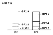
図9を用いてBP補正値BP2からBP補正値BP3を精度よく算出する方法について説明する。図9はBP補正値BP2とBP補正値BP3のBP補正量を示している。BP補正値BP2は縦横BP2−1と色BP2−2と空間周波数BP2−3の和として示されている。BP補正値BP3は縦横BP3−1と色BP3−2と空間周波数BP3−3の和として示されている。 A method for accurately calculating the BP correction value BP3 from the BP correction value BP2 will be described with reference to FIG. FIG. 9 shows BP correction amounts of the BP correction value BP2 and the BP correction value BP3. The BP correction value BP2 is shown as the sum of the vertical and horizontal BP2-1, the color BP2-2, and the spatial frequency BP2-3. The BP correction value BP3 is shown as the sum of the vertical and horizontal BP3-1, the color BP3-2, and the spatial frequency BP3-3.
焦点検出方式や撮像素子122の読み出しモードは異なるが、縦横BPの量はほぼ変わらないため、縦横BP2−1と縦横BP3−1はおおむね同量である。一方、図9では、焦点検出信号として、撮像面位相差AFでは、輝度信号Yを用いて、TVAFではG(緑)信号を用いた場合を示している。そのため、色BP2−2に対して色BP3−2は値が大きくなっている。さらに、撮像素子122の読み出しモードが異なるため、空間周波数BPに関して、空間周波数BP2−3は空間周波数BP3−3より値が大きくなっている。
Although the focus detection method and the reading mode of the
このような場合にBP補正値BP2からBP補正値BP3を算出するためには、オフセット成分O3として、縦横BP2−1と色BP2−2の和に相当した値を持てばよい。そして、ゲイン成分G2として、空間周波数BP2−3に対する空間周波数BP3−3の比に相当した値を持てばよい。さらに、オフセット成分O4として、縦横BP3−1と色BP3−2の和に相当した値を持てばよい。これらのオフセット成分、ゲイン成分を用いることにより、BP補正値BP3は式(4)により十分に高精度な補正を行うことができる。 To calculate the BP correction value BP3 from BP correction value BP2 In such a case, as an offset component O 3, it may be able to have considerable value to the sum of the vertical and horizontal BP2-1 and color BP2-2. Then, as the gain component G 2, simply needs to have a value corresponding to the ratio of the spatial frequency BP3-3 against spatial frequency BP2-3. Furthermore, the offset component O 4 may have a value corresponding to the sum of the vertical and horizontal BP3-1 and the color BP3-2. By using these offset components and gain components, the BP correction value BP3 can be corrected with sufficiently high accuracy by the equation (4).
なお、焦点検出信号に用いられる色が同じ場合や縦横BP補正値が小さい場合などには、BP補正値BP1、BP3、BP4を算出する際に用いられる2つのオフセット成分は同じ値を有してもよい。 When the color used for the focus detection signal is the same or when the vertical and horizontal BP correction values are small, the two offset components used when calculating the BP correction values BP1, BP3, and BP4 have the same value. Also good.
S102では、S101で設定された焦点検出方法及び読み出しモードに対応するBP補正値を、上述した方法により算出する。 In S102, the BP correction value corresponding to the focus detection method and readout mode set in S101 is calculated by the method described above.
このように簡易的にBP補正値BP1、BP3、BP4は算出されるため、BP補正値の精度はBP2には劣るが、必要なBP補正量が小さいため、焦点検出精度に与える影響は小さく、十分に高精度な焦点検出を行うことができる。一方で、BP補正値BP1、BP3、BP4の算出に必要な情報は、オフセット成分とゲイン成分のみで済むため、データの記憶容量の低減、BP補正値演算負荷を低減することができる。 Since the BP correction values BP1, BP3, and BP4 are simply calculated in this way, the accuracy of the BP correction value is inferior to that of BP2, but since the necessary BP correction amount is small, the influence on the focus detection accuracy is small. Sufficiently accurate focus detection can be performed. On the other hand, since the information necessary for calculating the BP correction values BP1, BP3, and BP4 is only the offset component and the gain component, the data storage capacity can be reduced and the BP correction value calculation load can be reduced.
なお、ゲイン成分は、1以下の値を乗じて、より小さいBP補正値を算出する際に用いるのが望ましいが、BP補正値の算出方法はこれに限らない。撮影状況が暗い場合などは、焦点検出信号のS/N比が悪化するため、S/N比向上のために焦点検出信号の評価する空間周波数帯域を下げる場合がある。このような場合には、空間周波数BPの量は大きくなるため、ゲイン成分として1より大きい値を乗じて補正してもよい。 The gain component is desirably used when a smaller BP correction value is calculated by multiplying a value of 1 or less, but the method for calculating the BP correction value is not limited to this. When the shooting situation is dark, the S / N ratio of the focus detection signal is deteriorated, and thus the spatial frequency band evaluated by the focus detection signal may be lowered to improve the S / N ratio. In such a case, since the amount of the spatial frequency BP becomes large, the gain component may be multiplied by a value larger than 1 for correction.
また、上述の説明では、主に補正値の計算をカメラMPU125で行ったが、本発明はこれに限るものではなく、例えば、レンズMPU117で補正値の計算を行ってもよい。その場合には、カメラMPU125から、レンズMPU117に対して、各種情報を送信し、レンズMPU117内でBP補正値の算出を行ってもよい。その場合には、図7のS22で、カメラMPU125から送信された合焦位置に対して、レンズMPU117が補正を施して、レンズ駆動を行えばよい。
In the above description, the correction value is calculated mainly by the
また、第1の実施形態では、撮影光学系の特性に起因する誤差を最も生じやすいケース(2)のBP補正値を基準となる補正値(基準補正値)として、ケース(1)、(3)、(4)のBP補正値BP1、BP3、BP4を簡易的に算出する場合について説明した。しかしながら、本発明はこれに限るものではなく、例えば、撮像装置が対応可能な複数の読み出し方法と複数の焦点検出方法の組み合わせのうち、予め決められた組み合わせについて基準となる補正値(基準補正値)を求めるようにしてもよい。そして、この場合、その他の組み合わせのBP補正値については、上述したようにオフセット成分及びゲイン成分を用いて簡易的に算出すればよい。 Further, in the first embodiment, cases (1), (3) are defined with reference to the BP correction value (reference correction value) of the case (2) in which an error due to the characteristics of the photographing optical system is most likely to occur. ), (4) The case where the BP correction values BP1, BP3, and BP4 are simply calculated has been described. However, the present invention is not limited to this. For example, among the combinations of a plurality of readout methods and a plurality of focus detection methods that can be handled by the imaging apparatus, a correction value that serves as a reference for a predetermined combination (reference correction value) ) May be requested. In this case, other combinations of BP correction values may be simply calculated using the offset component and the gain component as described above.
<第2の実施形態>
次に、図10を参照して、本発明の第2の実施形態について説明する。第1の実施形態との主な違いは、複数の種類のカメラ本体によって、焦点検出方式や撮像素子の読み出しモードなどが異なる点である。第1の実施形態では、1種類のカメラ本体内に、複数の焦点検出方式や撮像素子の読み出しモードが存在し、各々に対応したBP補正値を用いて焦点検出結果の補正を行った。第2の実施形態では、焦点検出方式や撮像素子の読み出しモードなどが異なるカメラ間でも、BP補正を行うことを可能にする。
<Second Embodiment>
Next, a second embodiment of the present invention will be described with reference to FIG. The main difference from the first embodiment is that the focus detection method, the readout mode of the image sensor, and the like differ depending on a plurality of types of camera bodies. In the first embodiment, there are a plurality of focus detection methods and image sensor reading modes in one type of camera body, and the focus detection result is corrected using the BP correction value corresponding to each. In the second embodiment, it is possible to perform BP correction even between cameras having different focus detection methods and image sensor reading modes.
なお、第2の実施形態における撮像装置の基本的な構成、焦点検出方式、焦点検出処理及びBP補正値の算出方法は、上述した第1の実施形態と同様であるため、ここでは説明を省略する。 Note that the basic configuration, focus detection method, focus detection process, and BP correction value calculation method of the image pickup apparatus in the second embodiment are the same as those in the first embodiment described above, and thus the description thereof is omitted here. To do.
以下、第2の実施形態における撮像システムのレンズユニットと複数の種類の着脱可能なカメラ本体の間でやり取りされる情報について説明する。なお、複数の種類のカメラ本体であることを示すために、以下、カメラ本体120a、120b、120cと記す。
Hereinafter, information exchanged between the lens unit of the imaging system according to the second embodiment and a plurality of types of removable camera bodies will be described. In order to indicate that there are a plurality of types of camera bodies, the camera bodies will be referred to as
図10は、撮像システムにおけるレンズユニット100と、着脱可能なカメラ本体120a、120b、120cを示している。レンズユニット100内のレンズメモリ118には、BP補正値を算出するための係数として、第1の実施形態の式(2)で用いた6つの補正値算出係数(C0〜C5)と、焦点検出方式や撮像素子の読み出しモードに対応したオフセット成分、ゲイン成分(O1〜O4、G1、G2)を記憶している。
FIG. 10 shows the
カメラ本体120aは、第2の読み出しモードで撮像面位相差AFを行うものとする。また、カメラ本体120bは、第1の読み出しモードで撮像面位相差AFを行うものとし、カメラ本体120cは、第1の読み出しモードでTVAFを行うものとする。
The
カメラ本体120aにレンズユニット100が装着された場合、カメラ本体120aのカメラMPU125は、BP補正値を算出する際に、補正値算出係数(C0〜C5)を通信により取得する。その後、第1の実施形態の式(2)によりBP補正値を算出する。
When the
カメラ本体120bにレンズユニット100が装着された場合、カメラ本体120bのカメラMPU125は、BP補正値を算出する際に、補正値算出係数(C0〜C5)とオフセット成分、ゲイン成分(O1、O2、G1)を通信により取得する。その後、第1の実施形態で説明した式(2)及び式(3)によりBP補正値を算出し、調整する。
When the
カメラ本体120cにレンズユニット100が装着された場合、カメラ本体120cのカメラMPU125は、BP補正値を調整する際に、補正値算出係数(C0〜C5)とオフセット成分、ゲイン成分(O3、O4、G2)を通信により取得する。その後、第1の実施形態の式(2)及び式(4)によりBP補正値を算出する。
When the
このように構成することにより、一つのレンズユニットに対して、複数の種類のカメラ本体が装着された場合にも、比較的簡易な構成で、高精度にBP補正を行うことができる。 With this configuration, even when a plurality of types of camera bodies are attached to one lens unit, BP correction can be performed with high accuracy with a relatively simple configuration.
なお、上記第1及び第2の実施形態では、読み出しモードと焦点検出方法との組み合わせに応じてBP補正値を算出する場合について説明したが、焦点検出方法のみに応じてBP補正値を算出するようにしてもよい。 In the first and second embodiments, the case where the BP correction value is calculated according to the combination of the reading mode and the focus detection method has been described. However, the BP correction value is calculated only according to the focus detection method. You may do it.
100:レンズユニット、104:フォーカスレンズ群、113:フォーカスアクチュエータ、117:レンズMPU、118:レンズメモリ、120:カメラ本体、122:撮像素子、125:カメラMPU、125a:RAM、129:撮像面位相差焦点検出部、130:TVAF焦点検出部 DESCRIPTION OF SYMBOLS 100: Lens unit, 104: Focus lens group, 113: Focus actuator, 117: Lens MPU, 118: Lens memory, 120: Camera main body, 122: Image sensor, 125: Camera MPU, 125a: RAM, 129: Image plane Phase difference focus detection unit, 130: TVAF focus detection unit
Claims (22)
前記評価値を、検出に用いられた焦点検出方法に応じて補正する補正手段と、
前記複数の異なる焦点検出方法のうち、予め決められた焦点検出方法を用いて検出された評価値を補正するための基準補正値を算出するための情報と、前記予め決められた焦点検出方法を除く焦点検出方法を用いて検出された評価値を補正するための補正値を、前記基準補正値から算出するための情報とを記憶した記憶手段とを有し、
前記補正手段は、前記記憶手段に記憶された情報を用いて、前記評価値を補正するための補正値を算出して、前記補正を行うことを特徴とする撮像装置。 A focus detection means for detecting an evaluation value for controlling the photographing optical system in a focused state using any of a plurality of different focus detection methods based on a signal output from the image sensor;
Correction means for correcting the evaluation value according to the focus detection method used for detection;
Information for calculating a reference correction value for correcting an evaluation value detected using a predetermined focus detection method among the plurality of different focus detection methods, and the predetermined focus detection method. Storage means storing information for calculating a correction value for correcting the evaluation value detected using the focus detection method excluding the reference correction value;
An image pickup apparatus, wherein the correction unit calculates the correction value for correcting the evaluation value using the information stored in the storage unit, and performs the correction.
前記焦点検出手段に用いられる複数の焦点検出方法は、前記位相差検出用の信号に基づいて行われる位相差方式の焦点検出方法を含むことを特徴とする請求項1乃至6のいずれか1項に記載の撮像装置。 The plurality of focus detection methods used in the focus detection means include a phase difference type focus detection method performed based on the phase difference detection signal. The imaging device described in 1.
前記撮像素子から出力された信号に基づいて、複数の異なる焦点検出方法のいずれかを用いて、撮影光学系を合焦状態に制御するための評価値を検出する焦点検出手段と、
前記評価値を、撮影時の解像度及び検出に用いられた焦点検出方法の組み合わせに応じて補正する補正手段と、
前記異なる解像度及び前記複数の異なる焦点検出方法の複数の組み合わせのうち、予め決められた組み合わせで検出された評価値を補正するための基準補正値を算出するための情報と、前記予め決められた組み合わせを除く組み合わせで検出された評価値を補正するための補正値を、前記基準補正値から算出するための情報とを記憶した記憶手段とを有し、
前記補正手段は、前記記憶手段に記憶された情報を用いて、前記評価値を補正するための補正値を算出して、前記補正を行うことを特徴とする撮像装置。 Image sensors that can be read at different resolutions;
A focus detection means for detecting an evaluation value for controlling the photographing optical system in a focused state using any one of a plurality of different focus detection methods based on a signal output from the image sensor;
Correction means for correcting the evaluation value according to the combination of the resolution at the time of shooting and the focus detection method used for detection;
Information for calculating a reference correction value for correcting an evaluation value detected in a predetermined combination among a plurality of combinations of the different resolutions and the plurality of different focus detection methods, and the predetermined Storage means storing information for calculating a correction value for correcting an evaluation value detected by a combination excluding the combination from the reference correction value;
An image pickup apparatus, wherein the correction unit calculates the correction value for correcting the evaluation value using the information stored in the storage unit, and performs the correction.
前記焦点検出手段に用いられる複数の焦点検出方法は、前記位相差検出用の信号に基づいて行われる位相差方式の焦点検出方法を含むことを特徴とする請求項9乃至14のいずれか1項に記載の撮像装置。 The imaging device has a plurality of photoelectric conversion units for one microlens, and includes a plurality of pixels that output a signal for phase difference detection,
A plurality of focus detection method used in the focus detecting means, any one of claims 9 to 14, characterized in that it comprises a focus detection method of the phase difference method which is performed on the basis of a signal for the phase difference detection The imaging device described in 1.
前記撮像装置が、
撮像素子から出力された信号に基づいて、撮影光学系を合焦状態に制御するための評価値を検出する焦点検出手段と、
前記評価値を、検出に用いられた焦点検出方法に応じて補正する補正手段とを有し、
前記撮影光学系が、
複数の異なる焦点検出方法のうち、予め決められた焦点検出方法を用いて検出された評価値を補正するための基準補正値を算出するための情報と、前記予め決められた焦点検出方法を除く焦点検出方法を用いて検出された評価値を補正するための補正値を、前記基準補正値から算出するための情報とを記憶した記憶手段とを有し、
前記撮影光学系は、前記記憶手段に記憶された情報のうち、前記焦点検出手段が検出に用いた焦点検出方法に応じた情報を前記撮像装置に出力し、
前記補正手段は、前記撮影光学系から出力された情報を用いて、前記評価値を補正するための補正値を算出して、前記補正を行うことを特徴とする撮像システム。 In an imaging system including an imaging optical system and an imaging device,
The imaging device is
A focus detection means for detecting an evaluation value for controlling the photographing optical system in a focused state based on a signal output from the image sensor;
Correction means for correcting the evaluation value according to the focus detection method used for detection,
The photographing optical system is
Excluding information for calculating a reference correction value for correcting an evaluation value detected using a predetermined focus detection method among a plurality of different focus detection methods, and the predetermined focus detection method Storage means for storing a correction value for correcting the evaluation value detected using the focus detection method, and information for calculating from the reference correction value;
The imaging optical system, of the information stored in the storage means, and outputs the information which the focus detection unit corresponding to the focus detection method had use in detection in the image pickup device,
The correction system calculates the correction value for correcting the evaluation value using the information output from the photographing optical system, and performs the correction.
前記撮像装置が、
異なる解像度で読み出し可能な撮像素子と、
前記撮像素子から出力された信号に基づいて、撮影光学系を合焦状態に制御するための評価値を検出する焦点検出手段と、
前記評価値を、撮影時の解像度及び検出に用いられた焦点検出方法に応じて補正する補正手段とを有し、
前記撮影光学系が、
複数の異なる解像度と複数の異なる焦点検出方法の複数の組み合わせのうち、予め決められた組み合わせで検出された評価値を補正するための基準補正値を算出するための情報と、前記予め決められた組み合わせを除く組み合わせで検出された評価値を補正するための補正値を、前記基準補正値から算出するための情報とを記憶した記憶手段とを有し、
前記撮影光学系は、前記記憶手段に記憶された情報のうち、前記撮像装置で用いられた組み合わせに応じた情報を前記撮像装置に出力し、
前記補正手段は、前記撮影光学系から出力された情報を用いて、前記評価値を補正するための補正値を算出して、前記補正を行うことを特徴とする撮像システム。 In an imaging system including an imaging optical system and an imaging device,
The imaging device is
Image sensors that can be read at different resolutions;
A focus detection unit that detects an evaluation value for controlling the photographing optical system in a focused state based on a signal output from the image sensor;
Correction means for correcting the evaluation value according to the resolution at the time of shooting and the focus detection method used for detection,
The photographing optical system is
Information for calculating a reference correction value for correcting an evaluation value detected by a predetermined combination among a plurality of combinations of a plurality of different resolutions and a plurality of different focus detection methods, and the predetermined Storage means storing information for calculating a correction value for correcting an evaluation value detected by a combination excluding the combination from the reference correction value;
The imaging optical system outputs information corresponding to the combination used in the imaging device among the information stored in the storage unit to the imaging device,
The correction system calculates the correction value for correcting the evaluation value using the information output from the photographing optical system, and performs the correction.
前記複数の異なる焦点検出方法のうち、予め決められた焦点検出方法を用いて検出された評価値を補正するための基準補正値を算出するための情報と、前記予め決められた焦点検出方法を除く焦点検出方法を用いて検出された評価値を補正するための補正値を、前記基準補正値から算出するための情報とを記憶した記憶手段から、取得手段が、前記焦点検出工程で用いられた焦点検出方法に応じた情報を取得する取得工程と、
補正手段が、前記取得工程で取得した情報を用いて、前記評価値を補正するための補正値を算出する算出工程と、
前記補正手段が、前記検出された評価値を、前記算出された補正値を用いて補正する補正工程と
を有することを特徴とする撮像装置の制御方法。 A focus detection step in which the focus detection means detects an evaluation value for controlling the photographing optical system in a focused state using any one of a plurality of different focus detection methods based on a signal output from the image sensor; ,
Information for calculating a reference correction value for correcting an evaluation value detected using a predetermined focus detection method among the plurality of different focus detection methods, and the predetermined focus detection method. An acquisition unit is used in the focus detection step from a storage unit that stores information for calculating a correction value for correcting an evaluation value detected using a focus detection method excluding the reference correction value. An acquisition step of acquiring information according to the focus detection method;
A calculation step in which a correction unit calculates a correction value for correcting the evaluation value using the information acquired in the acquisition step;
A control method for an imaging apparatus, comprising: a correction step in which the correction unit corrects the detected evaluation value using the calculated correction value.
前記異なる解像度及び前記複数の異なる焦点検出方法の複数の組み合わせのうち、予め決められた組み合わせで検出された評価値を補正するための基準補正値を算出するための情報と、前記予め決められた組み合わせを除く組み合わせで検出された評価値を補正するための補正値を、前記基準補正値から算出するための情報とを記憶した記憶手段から、取得手段が、前記焦点検出工程で用いられた組み合わせに応じた情報を取得する取得工程と、
補正手段が、前記取得工程で取得した情報を用いて、前記評価値を補正するための補正値を算出する算出工程と、
前記補正手段が、前記検出された評価値を、前記算出された補正値を用いて補正する補正工程と
を有することを特徴とする撮像装置の制御方法。 An evaluation value for controlling the photographing optical system to the in-focus state using any one of a plurality of different focus detection methods based on signals output from image sensors that can be read at different resolutions by the focus detection unit. A focus detection step to detect;
Information for calculating a reference correction value for correcting an evaluation value detected in a predetermined combination among a plurality of combinations of the different resolutions and the plurality of different focus detection methods, and the predetermined The combination used by the acquisition unit in the focus detection step from the storage unit storing the correction value for correcting the evaluation value detected by the combination excluding the combination and the information for calculating the reference correction value. An acquisition process for acquiring information according to
A calculation step in which a correction unit calculates a correction value for correcting the evaluation value using the information acquired in the acquisition step;
A control method for an imaging apparatus, comprising: a correction step in which the correction unit corrects the detected evaluation value using the calculated correction value.
Priority Applications (2)
| Application Number | Priority Date | Filing Date | Title |
|---|---|---|---|
| JP2014114371A JP6298362B2 (en) | 2014-06-02 | 2014-06-02 | Imaging apparatus, control method therefor, and imaging system |
| US14/722,446 US9407813B2 (en) | 2014-06-02 | 2015-05-27 | Image capturing apparatus, control method of image capturing apparatus, and image capturing system |
Applications Claiming Priority (1)
| Application Number | Priority Date | Filing Date | Title |
|---|---|---|---|
| JP2014114371A JP6298362B2 (en) | 2014-06-02 | 2014-06-02 | Imaging apparatus, control method therefor, and imaging system |
Publications (3)
| Publication Number | Publication Date |
|---|---|
| JP2015227995A JP2015227995A (en) | 2015-12-17 |
| JP2015227995A5 JP2015227995A5 (en) | 2017-07-13 |
| JP6298362B2 true JP6298362B2 (en) | 2018-03-20 |
Family
ID=54703274
Family Applications (1)
| Application Number | Title | Priority Date | Filing Date |
|---|---|---|---|
| JP2014114371A Active JP6298362B2 (en) | 2014-06-02 | 2014-06-02 | Imaging apparatus, control method therefor, and imaging system |
Country Status (2)
| Country | Link |
|---|---|
| US (1) | US9407813B2 (en) |
| JP (1) | JP6298362B2 (en) |
Families Citing this family (8)
| Publication number | Priority date | Publication date | Assignee | Title |
|---|---|---|---|---|
| JP6478457B2 (en) * | 2014-01-23 | 2019-03-06 | キヤノン株式会社 | Focus adjustment device and focus adjustment method |
| TWI554098B (en) * | 2014-10-07 | 2016-10-11 | 緯創資通股份有限公司 | Video recording device and associated video recording method |
| JP6600162B2 (en) * | 2015-05-19 | 2019-10-30 | キヤノン株式会社 | Imaging apparatus and control method thereof |
| JP6474693B2 (en) * | 2015-06-19 | 2019-02-27 | オリンパス株式会社 | Focus detection apparatus, focus detection method, and recording medium |
| JP6504969B2 (en) * | 2015-08-19 | 2019-04-24 | キヤノン株式会社 | Imaging system, imaging apparatus, lens apparatus, control method of imaging system |
| JP6628678B2 (en) * | 2016-04-21 | 2020-01-15 | キヤノン株式会社 | Distance measuring device, imaging device, and distance measuring method |
| JP6987524B2 (en) * | 2017-04-24 | 2022-01-05 | キヤノン株式会社 | Control device, image pickup device, control method, program, and storage medium |
| JP2019035825A (en) * | 2017-08-10 | 2019-03-07 | キヤノン株式会社 | Imaging device |
Family Cites Families (12)
| Publication number | Priority date | Publication date | Assignee | Title |
|---|---|---|---|---|
| JP2003295047A (en) * | 2002-04-05 | 2003-10-15 | Canon Inc | Image pickup device and image pickup system |
| US8259216B2 (en) * | 2007-08-29 | 2012-09-04 | Panasonic Corporation | Interchangeable lens camera system having autofocusing function |
| JP5153542B2 (en) | 2008-09-25 | 2013-02-27 | キヤノン株式会社 | Automatic focus adjustment device and focus adjustment method |
| JP5237059B2 (en) | 2008-11-14 | 2013-07-17 | キヤノン株式会社 | Focus detection apparatus and method, and imaging apparatus |
| JP5653035B2 (en) * | 2009-12-22 | 2015-01-14 | キヤノン株式会社 | Imaging apparatus, focus detection method, and control method |
| KR101579737B1 (en) * | 2010-01-05 | 2015-12-23 | 삼성전자주식회사 | Auto focus adjusting apparatus and camera system |
| JP2013008018A (en) * | 2011-05-25 | 2013-01-10 | Canon Inc | Imaging device and control method thereof |
| JP5896763B2 (en) * | 2012-02-02 | 2016-03-30 | キヤノン株式会社 | Optical instrument and method for autofocusing |
| JP5914055B2 (en) * | 2012-03-06 | 2016-05-11 | キヤノン株式会社 | Imaging device |
| JP6239857B2 (en) * | 2013-05-13 | 2017-11-29 | キヤノン株式会社 | Imaging apparatus and control method thereof |
| JP6194642B2 (en) * | 2013-05-31 | 2017-09-13 | 株式会社ニコン | interchangeable lens |
| JP6313685B2 (en) * | 2014-05-01 | 2018-04-18 | キヤノン株式会社 | Imaging apparatus and control method thereof |
-
2014
- 2014-06-02 JP JP2014114371A patent/JP6298362B2/en active Active
-
2015
- 2015-05-27 US US14/722,446 patent/US9407813B2/en active Active
Also Published As
| Publication number | Publication date |
|---|---|
| US9407813B2 (en) | 2016-08-02 |
| JP2015227995A (en) | 2015-12-17 |
| US20150350527A1 (en) | 2015-12-03 |
Similar Documents
| Publication | Publication Date | Title |
|---|---|---|
| US10212334B2 (en) | Focusing adjustment apparatus and focusing adjustment method | |
| JP6298362B2 (en) | Imaging apparatus, control method therefor, and imaging system | |
| JP6429546B2 (en) | Imaging apparatus, control method, program, and storage medium | |
| US9641769B2 (en) | Image capture apparatus and method for controlling the same | |
| US20170318217A1 (en) | Image capturing apparatus and method for controlling image capturing apparatus | |
| JP6682310B2 (en) | Focus detection apparatus and method, and imaging apparatus | |
| JP6843604B2 (en) | Information processing device and information processing method | |
| JP6415140B2 (en) | Imaging apparatus and control method thereof | |
| JP2014153509A (en) | Imaging device and imaging method | |
| JP6849325B2 (en) | Control device, image pickup device, control method, program, and storage medium | |
| JP6854619B2 (en) | Focus detection device and method, imaging device, lens unit and imaging system | |
| JP6890937B2 (en) | Focus detector, image pickup device, and focus detection method | |
| US20200092489A1 (en) | Optical apparatus, control method, and non-transitory computer-readable storage medium | |
| JP2017223760A (en) | Imaging device and focus adjustment method | |
| JP6744933B2 (en) | Lens part and its control method | |
| JP6685769B2 (en) | Information processing device, imaging device, and information processing method | |
| JP6686191B2 (en) | Focus detection device, imaging device, and focus detection method | |
| JP6686239B1 (en) | Lens unit, transmitter, and receiver | |
| JP6415054B2 (en) | Imaging apparatus and imaging method | |
| JP6548626B2 (en) | Image pickup apparatus, control method for image pickup apparatus, and focus control program | |
| JP2020003686A (en) | Focus detection device, imaging apparatus, and interchangeable lens device |
Legal Events
| Date | Code | Title | Description |
|---|---|---|---|
| A521 | Request for written amendment filed |
Free format text: JAPANESE INTERMEDIATE CODE: A523 Effective date: 20170531 |
|
| A621 | Written request for application examination |
Free format text: JAPANESE INTERMEDIATE CODE: A621 Effective date: 20170531 |
|
| A977 | Report on retrieval |
Free format text: JAPANESE INTERMEDIATE CODE: A971007 Effective date: 20171227 |
|
| TRDD | Decision of grant or rejection written | ||
| A01 | Written decision to grant a patent or to grant a registration (utility model) |
Free format text: JAPANESE INTERMEDIATE CODE: A01 Effective date: 20180126 |
|
| A61 | First payment of annual fees (during grant procedure) |
Free format text: JAPANESE INTERMEDIATE CODE: A61 Effective date: 20180223 |
|
| R151 | Written notification of patent or utility model registration |
Ref document number: 6298362 Country of ref document: JP Free format text: JAPANESE INTERMEDIATE CODE: R151 |