JP6274663B2 - Anti-counterfeit medium and method for producing the same - Google Patents
Anti-counterfeit medium and method for producing the same Download PDFInfo
- Publication number
- JP6274663B2 JP6274663B2 JP2014091133A JP2014091133A JP6274663B2 JP 6274663 B2 JP6274663 B2 JP 6274663B2 JP 2014091133 A JP2014091133 A JP 2014091133A JP 2014091133 A JP2014091133 A JP 2014091133A JP 6274663 B2 JP6274663 B2 JP 6274663B2
- Authority
- JP
- Japan
- Prior art keywords
- image data
- latent image
- color
- image
- pattern
- Prior art date
- Legal status (The legal status is an assumption and is not a legal conclusion. Google has not performed a legal analysis and makes no representation as to the accuracy of the status listed.)
- Active
Links
- 238000004519 manufacturing process Methods 0.000 title claims description 24
- 239000000976 ink Substances 0.000 claims description 112
- 239000000463 material Substances 0.000 claims description 36
- 238000000926 separation method Methods 0.000 claims description 33
- 239000000758 substrate Substances 0.000 claims description 24
- 239000003086 colorant Substances 0.000 claims description 12
- 238000010030 laminating Methods 0.000 claims description 7
- 230000002265 prevention Effects 0.000 claims description 6
- 238000007639 printing Methods 0.000 description 73
- 238000003860 storage Methods 0.000 description 20
- 238000010586 diagram Methods 0.000 description 19
- 238000000034 method Methods 0.000 description 16
- 238000000354 decomposition reaction Methods 0.000 description 9
- 239000011248 coating agent Substances 0.000 description 6
- 238000000576 coating method Methods 0.000 description 6
- 239000000049 pigment Substances 0.000 description 6
- 230000000007 visual effect Effects 0.000 description 5
- 239000004606 Fillers/Extenders Substances 0.000 description 4
- 238000006243 chemical reaction Methods 0.000 description 4
- 238000004891 communication Methods 0.000 description 4
- 239000007788 liquid Substances 0.000 description 4
- VTYYLEPIZMXCLO-UHFFFAOYSA-L Calcium carbonate Chemical compound [Ca+2].[O-]C([O-])=O VTYYLEPIZMXCLO-UHFFFAOYSA-L 0.000 description 2
- TZCXTZWJZNENPQ-UHFFFAOYSA-L barium sulfate Chemical compound [Ba+2].[O-]S([O-])(=O)=O TZCXTZWJZNENPQ-UHFFFAOYSA-L 0.000 description 2
- OSGAYBCDTDRGGQ-UHFFFAOYSA-L calcium sulfate Chemical compound [Ca+2].[O-]S([O-])(=O)=O OSGAYBCDTDRGGQ-UHFFFAOYSA-L 0.000 description 2
- 238000009826 distribution Methods 0.000 description 2
- 238000003475 lamination Methods 0.000 description 2
- 239000011159 matrix material Substances 0.000 description 2
- 238000002844 melting Methods 0.000 description 2
- 230000008018 melting Effects 0.000 description 2
- 238000002360 preparation method Methods 0.000 description 2
- 239000007787 solid Substances 0.000 description 2
- KXGFMDJXCMQABM-UHFFFAOYSA-N 2-methoxy-6-methylphenol Chemical class [CH]OC1=CC=CC([CH])=C1O KXGFMDJXCMQABM-UHFFFAOYSA-N 0.000 description 1
- 239000005909 Kieselgur Substances 0.000 description 1
- 241000220317 Rosa Species 0.000 description 1
- VYPSYNLAJGMNEJ-UHFFFAOYSA-N Silicium dioxide Chemical compound O=[Si]=O VYPSYNLAJGMNEJ-UHFFFAOYSA-N 0.000 description 1
- 239000000654 additive Substances 0.000 description 1
- PNEYBMLMFCGWSK-UHFFFAOYSA-N aluminium oxide Inorganic materials [O-2].[O-2].[O-2].[Al+3].[Al+3] PNEYBMLMFCGWSK-UHFFFAOYSA-N 0.000 description 1
- 229910000019 calcium carbonate Inorganic materials 0.000 description 1
- 239000000378 calcium silicate Substances 0.000 description 1
- 229910052918 calcium silicate Inorganic materials 0.000 description 1
- OYACROKNLOSFPA-UHFFFAOYSA-N calcium;dioxido(oxo)silane Chemical compound [Ca+2].[O-][Si]([O-])=O OYACROKNLOSFPA-UHFFFAOYSA-N 0.000 description 1
- 238000009792 diffusion process Methods 0.000 description 1
- 238000001035 drying Methods 0.000 description 1
- 230000000694 effects Effects 0.000 description 1
- 230000005284 excitation Effects 0.000 description 1
- 239000007850 fluorescent dye Substances 0.000 description 1
- 238000010438 heat treatment Methods 0.000 description 1
- 238000003384 imaging method Methods 0.000 description 1
- 239000003112 inhibitor Substances 0.000 description 1
- 239000000944 linseed oil Substances 0.000 description 1
- 235000021388 linseed oil Nutrition 0.000 description 1
- 239000004973 liquid crystal related substance Substances 0.000 description 1
- 239000002480 mineral oil Substances 0.000 description 1
- 235000010446 mineral oil Nutrition 0.000 description 1
- 238000007645 offset printing Methods 0.000 description 1
- 230000003647 oxidation Effects 0.000 description 1
- 238000007254 oxidation reaction Methods 0.000 description 1
- 230000035699 permeability Effects 0.000 description 1
- 239000004033 plastic Substances 0.000 description 1
- 238000007650 screen-printing Methods 0.000 description 1
- 239000003549 soybean oil Substances 0.000 description 1
- 235000012424 soybean oil Nutrition 0.000 description 1
- 239000000454 talc Substances 0.000 description 1
- 229910052623 talc Inorganic materials 0.000 description 1
Images


Landscapes
- Printing Methods (AREA)
- Credit Cards Or The Like (AREA)
Description
本発明は、銀行券、旅券、有価証券、商品タグ及び各種証明書等の貴重印刷物に偽造及び複製の防止用として施す秘匿情報を有する偽造防止媒体及びその作製方法に関するものである。 The present invention relates to an anti-counterfeit medium having confidential information to be used for preventing counterfeiting and duplication of valuable printed matter such as banknotes, passports, securities, product tags, and various certificates, and a method for producing the same.
従来から貴重印刷物には、その真偽を簡易に判別するために、判別具を用いずに真偽判別を行うことが可能な偽造防止策が多く付与されている。例えば、透過により真偽判別が可能なすき入れや、肉眼で真偽判別が可能な微小文字等が、多く付与されている。それに加え、観察角度の変化に伴う光沢の差により真偽判別が可能なパールインキ、透明インキ等の光沢材料が多く付与されている。 Conventionally, many anti-counterfeiting measures that can perform true / false discrimination without using a discriminating tool have been applied to valuable printed matter in order to easily determine the authenticity. For example, a lot of squeezing that can be distinguished by transparency, minute characters that can be judged by the naked eye, and the like are provided. In addition, a lot of glossy materials such as pearl ink and transparent ink, which can be determined by the difference in gloss accompanying the change in observation angle, are provided.
しかしながら、光沢材料は、出力装置及び材料が、シアン、マゼンタ等のプロセスインキやインクジェットインキとは異なるため、印刷するための材料及び出力装置を別途準備する必要がある。よって、通常の印刷物を形成する場合と比べ、手間及びコストがかかることから、材料及び出力装置を別途準備する必要がなく、通常のシアン、マゼンタ等のプロセスインキやインクジェットインキ等の印刷材料と出力装置を用いて、光沢画像を付与する技術が求められている。 However, since the output device and material of the glossy material are different from process ink and ink jet ink such as cyan and magenta, it is necessary to separately prepare a material and an output device for printing. Therefore, compared with the case of forming ordinary printed matter, it takes time and cost, so there is no need to prepare materials and output devices separately, and printing materials and output such as ordinary process inks such as cyan and magenta and inkjet inks are output. There is a need for a technique for providing a glossy image using an apparatus.
例えば、透明トナーを用いずに、レーザ・プリンタとトナーを用いて観察角度の変化による光沢を有する潜像画像が形成された印刷物として、特許文献1には、基材上に光沢画像を、トナー量100%でレーザ・プリンタにより付与し、光沢画像の周囲に背景領域をトナー量50%でレーザ・プリンタにより付与したのち、定着部でトナーを加熱し溶融させることで基材上に形成し、次に、その上に、背景領域の残りのトナー量50%を、レーザ・プリンタにより背景領域上に付与し、定着部でトナーを加熱し溶融させることで形成した印刷物が開示されている。
For example, as a printed matter in which a latent image having a gloss due to a change in observation angle is formed using a laser printer and toner without using a transparent toner,
二度定着部を通過した光沢画像は、二度トナーを加熱して溶融させることで、一度しか定着部を通過していない背景領域と比べて、表面が平坦形状となり光沢性が高くなる。よって、正面から視認した際には、光沢画像とその周囲の背景領域は、トナー量が同じであるため、濃度が一様な領域として視認されるが、観察角度の変化により、光沢性の高い光沢画像が、潜像画像として視認可能となる。 The gloss image that has passed through the fixing unit twice is heated and melted twice, so that the surface becomes flat and gloss is higher than the background area that has passed through the fixing unit only once. Therefore, when viewed from the front, the glossy image and the surrounding background area have the same amount of toner, so the density is visually recognized as a uniform density area. The glossy image becomes visible as a latent image.
特許文献1により、トナーを用いて光沢画像を形成することが可能となった。しかしながら、特許文献1では、光沢画像を、トナーを二度刷りしたのち、定着部で二度溶融させて平坦形状として形成する必要がある。よって、用いる材料はトナーに限定され、さらに、印刷機はトナーを溶融することが可能な定着部を有する出力機に限定される。
そこで、本発明は、インキ及び印刷機を限定することなく作製可能な、観察角度の変化により視認可能となる潜像画像を有する偽造防止媒体とその作製方法を提案することを目的とする。 Therefore, an object of the present invention is to propose an anti-counterfeit medium having a latent image that can be produced by changing the observation angle, and a production method thereof, which can be produced without limiting the ink and the printing press.
前述の目的を達成するために、請求項1記載の発明は、基材上における少なくとも一部に、カモフラージュ画像と潜像画像が積層して成る基材と異なる色の印刷模様を有するインキ受理領域を備え、カモフラージュ画像は、基材と異なる色の模様部が少なくとも第1のインキで形成され、模様部の周囲に形成された背景部は、基材と異なる色の少なくとも第2のインキで形成され、潜像画像は、模様部と同一形状、かつ、同じ大きさで背景部と毛抜き合わせで基材と異なる色の第3のインキで形成され、拡散反射光下において、背景部は、積層して成る模様部と潜像画像と等色であり、正反射光下において、積層して成る模様部及び潜像画像と、背景部は、同一入射光に対する反射光の差により、潜像画像が視認されることを特徴とする偽造防止媒体である。
In order to achieve the above-mentioned object, the invention according to
また、請求項2記載の発明は、第1のインキ、第2のインキ及び第3のインキは、同じ色であることを特徴とする請求項1記載の偽造防止媒体である。
The invention according to
また、請求項3記載の発明は、模様部及び背景部は、少なくとも二色のインキで形成されることを特徴とする請求項1記載の偽造防止媒体である。
The invention according to
また、請求項4記載の発明は、印刷模様は、カラーの階調画像であり、かつ、潜像画像は、階調画像であり、模様部と背景部の間に、基材及び背景部と異なる色の少なくとも第4のインキで形成された階調カモフラージュ部が配置され、模様部と潜像画像は、異なる色のインキで形成されたことを特徴とする請求項3記載の偽造防止媒体である。
In the invention according to
また、請求項5記載の発明は、請求項4記載の偽造防止媒体を作製する方法であって、印刷模様の原画像である印刷模様データと、潜像画像の原画像である潜像画像データを作製する画像データ取得ステップと、印刷模様データを色分解して複数の分解画像データを作製する色分解ステップと、複数の分解画像データ及び潜像画像データに対し、共通する位置情報である位置座標を設定した後、複数の分解画像データのうち、潜像画像データを隠ぺいさせる隠ぺい分解画像データと潜像画像データを重ねて重複箇所を除去し、隠ぺい用カモフラージュ画像データを作製するステップと、潜像画像データの色を、隠ぺい分解画像データと同じ色に設定し、色設定潜像画像データを作製するステップと、隠ぺい用カモフラージュ画像データと、隠ぺい用カモフラージュ画像データを作製する際に用いなかった、残りの各分解画像データを合成し、カモフラージュ画像データを作製するステップと、カモフラージュ画像データ及び色設定潜像画像データを積層して出力する出力ステップを備えることを特徴とする偽造防止媒体の作製方法である。
The invention according to
さらに、請求項6記載の発明は、出力ステップ前に、基材にインキ受理領域を形成するステップを備えることを特徴とする請求項5記載の偽造防止媒体の作製方法である。
Further, the invention described in
本発明の潜像画像を有する偽造防止媒体は、潜像画像を形成するインキを、インキ受理領域上に積層して印刷することで生じる、積層した箇所とその他の箇所での拡散性の差により、観察角度の変化で視認可能な潜像画像を形成する。よって、インキ及び印刷機に限定することなく形成することが可能なため、従来の光沢画像を有する印刷物よりも非常に安価で作製することが可能となる。 The anti-counterfeit medium having a latent image of the present invention is caused by a difference in diffusibility between the laminated portion and other portions, which is generated by laminating and printing the ink for forming the latent image on the ink receiving area. A visible latent image is formed by changing the observation angle. Therefore, since it can form without limiting to an ink and a printing machine, it becomes possible to produce at a very cheap price rather than the printed matter which has the conventional glossy image.
本発明の実施形態について図面を用いて説明する。しかしながら、本発明は、以下に述べる実施するための形態に限定されるものではなく、特許請求の範囲の記載における技術的思想の範囲内であれば、その他色々な形態が実施可能である。 Embodiments of the present invention will be described with reference to the drawings. However, the present invention is not limited to the embodiments to be described below, and various other embodiments can be implemented within the scope of the technical idea described in the claims.
図1は、本発明における偽造防止媒体(以下、「媒体」という。)(S1)の一実施例を示す平面図である。 FIG. 1 is a plan view showing an example of an anti-counterfeit medium (hereinafter referred to as “medium”) (S1) according to the present invention.
媒体(S1)は、例えば、紙幣、証券、パスポート、身分証明書等の貴重印刷物であり、
紙、プラスチックカード等の印刷可能な基材(1)上における少なくとも一部のインキ受理領域(Z)内に、基材(1)と異なる色の印刷模様(2)を有している。印刷模様(2)は、拡散反射光下では、一つの画像として視認されるが、正反射光下で視認可能となる、秘匿情報を有している。なお、本発明では、正反射時における反射光を「正反射光」という。
The medium (S1) is, for example, valuable printed matter such as banknotes, securities, passports, identification cards,
A printed pattern (2) having a color different from that of the substrate (1) is provided in at least a part of the ink receiving area (Z) on the printable substrate (1) such as paper or a plastic card. The printed pattern (2) is visually recognized as one image under diffusely reflected light, but has confidential information that can be visually recognized under regular reflected light. In the present invention, the reflected light at the time of regular reflection is referred to as “regular reflection light”.
図2は、印刷模様(2)を説明する平面図である。印刷模様(2)は、文字、数字、模様等の有意味情報を表しており、図2では、四角形状を表している。印刷模様(2)は、インキ受理領域(Z)内に、カモフラージュ画像(3)と潜像画像(6)が積層して成る。 FIG. 2 is a plan view for explaining the printed pattern (2). The printed pattern (2) represents meaningful information such as letters, numbers, and patterns, and in FIG. The printed pattern (2) is formed by laminating a camouflage image (3) and a latent image (6) in the ink receiving area (Z).
インキ受理領域(Z)とは、印刷模様(2)を形成するインキを拡散させる領域であり、例えば、多孔質の体質顔料を主体とした塗布液を塗工することで形成される。図3は、図2のX1−X1’におけるインキ受理領域(Z)の断面を説明する模式図である、図3(a)に示すように、インキ受理領域(Z)を有しない基材(1)上に、印刷模様(2)を印刷した場合、印刷模様(2)を形成するインキは、基材(1)上に付着したのち、硬化する。 The ink receiving area (Z) is an area for diffusing ink for forming the printed pattern (2), and is formed, for example, by applying a coating liquid mainly composed of a porous extender pigment. FIG. 3 is a schematic diagram for explaining a cross section of the ink receiving area (Z) in X1-X1 ′ of FIG. 2, as shown in FIG. 3 (a), a substrate having no ink receiving area (Z) ( 1) When the printed pattern (2) is printed on the ink, the ink for forming the printed pattern (2) is deposited on the substrate (1) and then cured.
一方、図3(b)に示すように、インキ受理領域(Z)を有する基材(1)上に、印刷模様(2)を印刷した場合、印刷模様(2)を形成するインキは、基材(1)上に付着し、インキ受理領域(Z)の内部に分散したのち、硬化する。 On the other hand, as shown in FIG. 3B, when the printed pattern (2) is printed on the substrate (1) having the ink receiving area (Z), the ink forming the printed pattern (2) It adheres on the material (1), is dispersed inside the ink receiving area (Z), and then hardens.
原理についての詳細は後述するが、本発明では、積層構造とすることで、積層箇所とその他の箇所で、インキ受理領域(Z)内における印刷回数が異なる。印刷回数とは、インキ受理領域(Z)にインキを付着させて、硬化させる回数のことであり、以下、「印刷回数」という。それにより、拡散反射光下では一つの画像として視認される印刷模様(2)が、正反射光下では、インキ受理領域(Z)内において、他の箇所と印刷回数が異なる潜像画像(6)が視認可能となる。よって、印刷模様(2)は、インキ受理領域(Z)内に形成する必要がある。 Although the details of the principle will be described later, in the present invention, the number of times of printing in the ink receiving area (Z) is different between the laminated portion and other portions by adopting a laminated structure. The number of times of printing is the number of times ink is applied to the ink receiving area (Z) and cured, and is hereinafter referred to as “number of times of printing”. As a result, the printed pattern (2) that is visually recognized as one image under diffuse reflected light is a latent image (6) that is printed differently from other places in the ink receiving area (Z) under regular reflected light. ) Becomes visible. Therefore, the printed pattern (2) needs to be formed in the ink receiving area (Z).
インキ受理領域(Z)を生成する多孔質の体質顔料としては、例えば、アルミナ白、タルク、炭酸カルシウム、硫酸バリウム、硫酸カルシウム、ケイソウ土、ケイ酸カルシウム等の白色顔料が挙げられ、これら体質顔料10〜25重量%を、例えばオフセット用メジウム(ロジン変性フェノール樹脂、大豆油、亜麻仁油、鉱物油等ビヒクルにドライヤーや酸化抑制剤等の添加剤から成る)に分散させたオフセットインキで印刷し、厚さ1〜5μm程度のインキ受理領域(Z)とすることができる。 Examples of porous extender pigments that produce the ink receiving area (Z) include white pigments such as alumina white, talc, calcium carbonate, barium sulfate, calcium sulfate, diatomaceous earth, and calcium silicate. 10-25% by weight is printed with offset ink dispersed in, for example, a medium for offset (including rosin-modified phenolic resin, soybean oil, linseed oil, mineral oil, etc., and additives such as a dryer and an oxidation inhibitor) The ink receiving area (Z) having a thickness of about 1 to 5 μm can be obtained.
上記オフセット用メジウムに代え、グラビア用メジウム、あるいはスクリーン印刷用、ロールコート用等とし、それぞれの方式で印刷又は塗工することも、可能である。 Instead of the offset medium, gravure medium, screen printing, roll coating, or the like can be used for printing or coating by the respective methods.
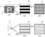
次に、カモフラージュ画像(3)と潜像画像(6)のそれぞれの構成について説明する。図4は、カモフラージュ画像(3)及び潜像画像(6)の構成を示す平面図である。図4(a1)に示すカモフラージュ画像(3)は、模様部(4)と、模様部(4)の周囲に配置された背景部(5)から成る。 Next, the configurations of the camouflage image (3) and the latent image (6) will be described. FIG. 4 is a plan view showing configurations of the camouflage image (3) and the latent image (6). A camouflage image (3) shown in FIG. 4A1 includes a pattern portion (4) and a background portion (5) arranged around the pattern portion (4).
カモフラージュ画像(3)は、模様部(4)と背景部(5)の濃度又は色が異なることで、文字、数字、模様等の有意味情報を表しており、図4(a1)では、模様部(4)により文字「P」を表している。 The camouflage image (3) represents meaningful information such as letters, numbers, and patterns due to the different density or color of the pattern portion (4) and the background portion (5). In FIG. The part “4” represents the letter “P”.
図4(a2)の拡大図に示すように、カモフラージュ画像(3)は、基材(1)とは異なる色のインキで形成されたカモフラージュ要素(3a)が万線状に配置されてなるか、又は、図4(a3)の拡大図に示すように、カモフラージュ要素(3a)がマトリックス状に配置されてなる。
As shown in the enlarged view of FIG. 4 (a2), the camouflage image (3) is formed by arranging camouflage elements (3a) formed of ink of a color different from that of the substrate (1) in a line shape. Alternatively, as shown in the enlarged view of FIG. 4 (a3) , the camouflage elements (3a) are arranged in a matrix.
模様部(4)は、基材(1)と異なる色の少なくとも第1のインキで形成される。カモフラージュ要素(3a)及び後述する潜像要素(6a)を配置するピッチは、印刷模様(2)の大きさ、印刷方式、要素の幅(W3)を考慮し、3000μm以下の範囲内で適宜設定される。 The pattern portion (4) is formed of at least a first ink having a color different from that of the substrate (1). The pitch for arranging the camouflage element (3a) and the latent image element (6a) described later is appropriately set within a range of 3000 μm or less in consideration of the size of the print pattern (2), the printing method, and the element width (W3). Is done.
ピッチが3000μmを超える場合には、ピッチが小さい場合と比べ、基材(1)が多く露出する。よって、用いる基材(1)によっては、基材(1)の正反射光における拡散性が影響することで、潜像画像(6)の視認性が低下し、好ましくない。 When the pitch exceeds 3000 μm, more substrate (1) is exposed than when the pitch is small. Therefore, depending on the base material (1) to be used, the visibility of the latent image (6) is lowered due to the influence of the diffusibility of the base material (1) in the regular reflection light, which is not preferable.
なお、図4では、カモフラージュ要素(3a)は一定ピッチで配置されているが、前述した範囲内であれば、一部異なるピッチとすることも可能である。 In FIG. 4, the camouflage elements (3a) are arranged at a constant pitch, but a part of the camouflage elements (3a) may be different from each other as long as they are within the above-described range.
カモフラージュ要素(3a)を配置するピッチを100μm未満とした場合は、図5に示すように、複数配置されたカモフラージュ要素(3a)は、隙間なく配置されることから、肉眼では、カモフラージュ画像(3)を形成する模様部(4)及び背景部(5)は、いずれもベタ領域として視認される。 When the pitch for arranging the camouflage elements (3a) is less than 100 μm, the plurality of camouflage elements (3a) are arranged without a gap as shown in FIG. The pattern portion (4) and the background portion (5) that form a) are both visually recognized as a solid region.
カモフラージュ要素(3a)の画線幅(W3)と、後述する潜像要素(6a)の画線幅(W4)は、それぞれ20〜2000μmの範囲内で適宜設定することが可能である。 The image line width (W3) of the camouflage element (3a) and the image line width (W4) of the latent image element (6a) described later can be appropriately set within a range of 20 to 2000 μm.
各要素(3a、4a)の画線幅(W3、W4)が、20μm未満の場合は、用いるインキの濃度によっては印刷模様(2)の視認性が悪くなる。また、模様部(4)及び潜像画像(6)を積層して配置しづらくなり、好ましくない。 When the line width (W3, W4) of each element (3a, 4a) is less than 20 μm, the visibility of the printed pattern (2) is deteriorated depending on the concentration of ink used. Further, it is difficult to stack the pattern portion (4) and the latent image (6), which is not preferable.
各要素(3a、4a)の画線幅(W3、W4)が、2000μmを超える場合は、積層して配置された模様部(4)及び潜像画像(6)と、背景部(5)の拡散性の差が肉眼で視認可能となり好ましくない。 When the line width (W3, W4) of each element (3a, 4a) exceeds 2000 μm, the pattern portion (4) and the latent image (6) arranged in a stacked manner and the background portion (5) The difference in diffusibility is not preferable because it is visible with the naked eye.
背景部(5)は、模様部(4)の周囲に配置された領域であり、基材(1)と異なる色の少なくとも第2のインキで形成される。背景部(5)は、拡散反射光下では、潜像画像(6)と同一形状、かつ、同じ大きさの模様部(4)の形状を隠ぺいするために、模様部(4)の周囲に配置する必要がある。 A background part (5) is an area | region arrange | positioned around a pattern part (4), and is formed with the at least 2nd ink of a color different from a base material (1). The background portion (5) is arranged around the pattern portion (4) in order to conceal the shape of the pattern portion (4) having the same shape and the same size as the latent image (6) under diffuse reflected light. Need to be placed.
模様部(4)と背景部(5)を形成するインキの色は、等色でも異なっていても良いが、潜像画像(6)を、拡散反射光下で隠ぺいするために、模様部(4)と潜像画像(6)が積層されたところと、背景部(5)を等色とする必要がある。 The color of the ink forming the pattern portion (4) and the background portion (5) may be the same color or different, but in order to conceal the latent image (6) under diffuse reflected light, the pattern portion ( 4) and the background image (6) need to be the same color where the latent image (6) is laminated.
例えば、模様部(4)を形成する青色とし、潜像画像(6)を黄色とした場合、背景部(5)は、模様部(4)と潜像画像(6)である青色と黄色が積層したところと等色の緑色とする。カモフラージュ画像(3)と潜像画像(6)を積層した場合、二度刷りで形成された模様部(4)及び潜像画像(6)は、緑色で視認される。また、一度刷りで形成された背景部(5)も緑色で視認される。なお、一度刷りとは、印刷回数が一回のことをいい、二度刷りとは、印刷回数が二回のことをいう。よって、印刷模様(2)は全体が一様な緑色として視認可能となり、潜像画像(6)が隠ぺいされる。各インキは、複数種類のインキから成る構成でも良い。 For example, when the pattern portion (4) is blue and the latent image (6) is yellow, the background portion (5) is blue and yellow, which are the pattern portion (4) and the latent image (6). The green color is the same as that of the laminated layer. When the camouflage image (3) and the latent image (6) are laminated, the pattern portion (4) and the latent image (6) formed by twice printing are visually recognized in green. Further, the background portion (5) once formed by printing is also visually recognized in green. Note that “one-time printing” means that the number of times of printing is one, and “twice-time” means that the number of times of printing is two. Therefore, the printed pattern (2) is visible as a uniform green color as a whole, and the latent image (6) is hidden. Each ink may be composed of a plurality of types of ink.
また、印刷模様(2)を1種類のインキで形成する場合には、模様部(4)と潜像画像(6)を積層した色と、背景部(5)の色を等色とするために、模様部(4)と潜像画像(6)を積層した濃度と、背景部(5)の濃度を同じ濃度とする。 Further, when the printed pattern (2) is formed with one kind of ink, the color obtained by laminating the pattern portion (4) and the latent image (6) and the color of the background portion (5) are made the same color. In addition, the density at which the pattern portion (4) and the latent image (6) are stacked and the density at the background portion (5) are the same.
例えば、模様部(4)を形成する第1のインキ、背景部(5)を形成する第2のインキ及び潜像画像(6)を形成する第3のインキを、同じ色の1種類のインキで形成する場合、模様部(4)を濃度50で形成し、潜像画像(6)を濃度50で形成し、背景部(5)を濃度100で形成する。それにより、カモフラージュ画像(3)と潜像画像(6)を積層した場合、全体が濃度100の一様な青色として視認可能となる。 For example, the first ink that forms the pattern portion (4), the second ink that forms the background portion (5), and the third ink that forms the latent image (6) are replaced with one type of ink of the same color. The pattern portion (4) is formed at a density of 50, the latent image (6) is formed at a density of 50, and the background portion (5) is formed at a density of 100. Thereby, when the camouflage image (3) and the latent image (6) are laminated, the whole can be visually recognized as a uniform blue color having a density of 100.
さらに、模様部(4)と背景部(5)を形成するインキは、蛍光材料を含んでいても良い。蛍光材料とは、紫外線又は赤外線を照射した際に可視発光をする蛍光顔料又は蛍光染料のことである。蛍光材料をインキに含むことで、前述した正反射光下で潜像画像(6)が視認可能となる効果に加え、蛍光材料の励起光下においては、模様部(4)又は背景部(5)が蛍光発光して視認可能となる。 Furthermore, the ink which forms a pattern part (4) and a background part (5) may contain the fluorescent material. The fluorescent material is a fluorescent pigment or fluorescent dye that emits visible light when irradiated with ultraviolet rays or infrared rays. By including the fluorescent material in the ink, in addition to the effect of making the latent image (6) visible under the specular reflection light described above, the pattern portion (4) or the background portion (5) under the excitation light of the fluorescent material. ) Becomes fluorescent and becomes visible.
模様部(4)と背景部(5)を形成するインキは、インキ受理領域(Z)に定着することが可能なインキであれば良く、例えばレーザ・プリンタで使用されるトナー、インクジェット・プリンタで使用されるプロセスインキとする。 The ink for forming the pattern portion (4) and the background portion (5) may be any ink that can be fixed in the ink receiving area (Z). For example, the toner used in a laser printer or an ink jet printer may be used. Process ink used.
模様部(4)と背景部(5)の配置については、図3で示した配置に限らず、拡散反射光下で、潜像画像(6)と同一形状の模様部(4)の形状が隠ぺい可能な配置であれば、適宜設定することが可能である。 The arrangement of the pattern portion (4) and the background portion (5) is not limited to the arrangement shown in FIG. 3, and the shape of the pattern portion (4) having the same shape as that of the latent image (6) is not limited to the arrangement shown in FIG. Any arrangement that can be concealed can be set as appropriate.
図6は、模様部(4)と背景部(5)の配置の一例を示す平面図である。図6(a)に示すように、模様部(4)の一部と隣接するように、背景部(5)を配置してもよい。また、図6(b)に示すように、模様部(4)は一つに限らず、複数配置しても良い。さらには、図6(c)に示すように、背景部(5)の周囲に模様部(4)を配置する、図4とは逆の配置としても良い。 FIG. 6 is a plan view showing an example of the arrangement of the pattern portion (4) and the background portion (5). As shown to Fig.6 (a), you may arrange | position a background part (5) so that a part of pattern part (4) may adjoin. Moreover, as shown in FIG.6 (b), not only one pattern part (4) may be arrange | positioned. Furthermore, as shown in FIG. 6C, the pattern portion (4) may be arranged around the background portion (5), and the arrangement may be opposite to that in FIG.
図4(b1)に示す潜像画像(6)は、正反射光下で視認可能となる画像であり、模様部(4)と同一形状、かつ、同じ大きさである。視認についての詳細は後述するが、模様部(4)の上又は下に、同一形状の潜像画像(6)を一致するように積層して配置し、その周囲に背景部(5)を毛抜き合わせで配置することで、拡散反射光下では、積層して配置された模様部(4)及び潜像画像(6)と、その周囲の背景部(5)が等色に視認されることで、潜像画像(6)を隠ぺいすることが可能となる。 The latent image (6) shown in FIG. 4 (b1) is an image that can be viewed under regular reflection light, and has the same shape and the same size as the pattern portion (4). The details of the visual recognition will be described later, but the same-shaped latent image (6) is laminated and arranged on or below the pattern portion (4), and the background portion (5) is tipped around it. By arranging them together, the pattern portion (4) and the latent image (6) arranged in a stacked manner and the surrounding background portion (5) are visually recognized in the same color under diffuse reflected light. The latent image (6) can be hidden.
一方、正反射光下では、積層して配置した模様部(4)及び潜像画像(6)と、その周囲の背景部(5)で、基材(1)への印刷回数が異なることで、同一入射光に対する反射光の差により潜像画像(6)が視認可能となる。 On the other hand, under regular reflection light, the number of times of printing on the base material (1) is different between the pattern portion (4) and the latent image (6) arranged in layers and the background portion (5) around the pattern portion (4). The latent image (6) becomes visible due to the difference in reflected light with respect to the same incident light.
図4(b2)の拡大図に示すように、潜像画像(6)は、基材(1)と異なる色の少なくとも第3のインキで形成された潜像要素(6a)が万線状に配置されてなるか、又は、図4(b3)の拡大図に示すように、潜像要素(6a)がマトリックス状に配置されてなる。カモフラージュ画像(3)と潜像画像(6)を形成するインキは、同じ色でも異なる色でも良い。以下、カモフラージュ画像(3)と潜像画像(6)が同じ色のインキとして説明する。 As shown in the enlarged view of FIG. 4 (b2), the latent image (6) has a latent image element (6a) formed of at least a third ink having a color different from that of the substrate (1). As shown in the enlarged view of FIG. 4 (b3), the latent image elements (6a) are arranged in a matrix. The inks forming the camouflage image (3) and the latent image (6) may be the same color or different colors. Hereinafter, the camouflage image (3) and the latent image (6) will be described as the same color ink.
本発明において、カモフラージュ要素(3a)及び潜像要素(6a)は、それぞれが画線、点、画素の少なくとも一つ又はそれぞれの組合せである。図7は、カモフラージュ要素(3a)及び潜像要素(6a)の形状を示す図であり、一例としてカモフラージュ要素(3a)を示す平面図である。 In the present invention, each of the camouflage element (3a) and the latent image element (6a) is at least one of an image line, a point, and a pixel, or a combination thereof. FIG. 7 is a diagram showing the shapes of the camouflage element (3a) and the latent image element (6a), and is a plan view showing the camouflage element (3a) as an example.
画線とは、図7(a)、図7(b)、図7(c)及び図7(d)に示すような、直線、破線、波線又は破線状の波線のことである。点とは、網目スクリーン、コンタクトスクリーン等により、印刷物上に構成された点である。点及び後述する画素は、直線状又は波線状に複数配置されて、点群又は画素群を形成する。 The image line is a straight line, a broken line, a wavy line, or a broken wavy line as shown in FIGS. 7A, 7B, 7C, and 7D. A point is a point formed on a printed material by a mesh screen, a contact screen, or the like. A plurality of dots and pixels to be described later are arranged in a straight line or a wavy line to form a point group or a pixel group.
点群又は画線群と成ることで画線状に構成されたカモフラージュ要素(3a)が、万線状に配置されることで、図4(a1)に示すカモフラージュ画像(3)となる。点形状は、円形ドットに限定されるものではなく、ランダムドットや本出願人が先に出願した特開平11−268228号公報で提案している特殊網点生成法を用いて意匠性を加味した入力画像を網点(ハーフトーンスクリーン)から成る、連続階調網点に変換した自由度のある特殊網点形状を用いても良い。 When the camouflage elements (3a) configured in a line shape by forming a point group or a line group are arranged in a line, the camouflage image (3) shown in FIG. 4 (a1) is obtained. The dot shape is not limited to a circular dot, but a random dot or a special halftone dot generation method proposed in Japanese Patent Application Laid-Open No. 11-268228 previously filed by the applicant of the present application is taken into consideration. A special halftone dot shape having a degree of freedom obtained by converting an input image into halftone dots consisting of halftone screens may be used.
画素とは、図形、文字等の二次元画像を縦横の線で分割した、その最小単位のことである。画素形状は、図7(e)、図7(f)、図7(g)、図7(h)、図7(i)及び図7(j)に示すような、円形状、楕円形状、多角形状、文字形状のことである。図7(h)に示した文字形状は、一般的に微小文字又は特殊網点と呼ばれるが、本発明では画素とする。さらに、図7(i)及び図7(j)に示すように、要素は、画線、点及び画素をそれぞれ組み合わせても良い。 A pixel is a minimum unit obtained by dividing a two-dimensional image such as a figure or a character by vertical and horizontal lines. The pixel shape is circular, elliptical, as shown in FIGS. 7 (e), 7 (f), 7 (g), 7 (h), 7 (i) and 7 (j). Polygonal shape and character shape. The character shape shown in FIG. 7H is generally called a minute character or a special halftone dot, but is a pixel in the present invention. Further, as shown in FIGS. 7 (i) and 7 (j), the elements may be combined with image lines, points, and pixels, respectively.
なお、積層して配置される、模様部(4)と潜像画像(6)を構成する要素は、同じ形状の要素で形成することが好ましい。模様部(4)と潜像画像(6)を、異なる形状の要素で形成した場合、拡散反射光下において、潜像画像(6)が視認可能となってしまう恐れがあり好ましくない。以下、本実施形態についてはカモフラージュ要素(3a)及び潜像要素(6a)を、図7(a)に示す直線状の画線として説明する。 In addition, it is preferable to form the element which comprises the pattern part (4) and latent image (6) arrange | positioned by lamination | stacking by the element of the same shape. When the pattern portion (4) and the latent image (6) are formed of elements having different shapes, the latent image (6) may be visible under diffuse reflected light, which is not preferable. Hereinafter, in the present embodiment, the camouflage element (3a) and the latent image element (6a) will be described as linear image lines shown in FIG.
次に、積層して配置された模様部(4)及び潜像画像(6)と、その周囲の背景部(5)が、印刷回数が異なることで、拡散性に差が生じる原理について説明する。 Next, the principle of causing a difference in diffusivity due to the number of times of printing of the pattern portion (4) and the latent image (6) arranged in a stacked manner and the surrounding background portion (5) will be described. .
図8は、積層して配置された模様部(4)及び潜像画像(6)と、背景部(5)の拡散性の差を示す模式図であり、図8(a)は、図2のX1−X1’断面における拡大図である。なお、本実施形態における拡散性とは、拡散反射光を入射した際の反射光のことである。よって、拡散性に差が生じるとは、同じ角度から、同じ光量の拡散反射光を入射した際に、反射光量が異なることをいう。以下、同じ角度から同じ光量の拡散反射光を入射することを、同一入射光という。 FIG. 8 is a schematic diagram showing a difference in diffusibility between the pattern portion (4) and the latent image (6) and the background portion (5) arranged in a stacked manner, and FIG. It is an enlarged view in X1-X1 'cross section. In addition, the diffusibility in this embodiment is reflected light when diffusely reflected light is incident. Thus, the difference in diffusivity means that the amount of reflected light differs when the same amount of diffusely reflected light is incident from the same angle. Hereinafter, the incidence of diffusely reflected light having the same light amount from the same angle is referred to as identical incident light.
図8(a)に示すように、印刷模様(2)は、基材(1)上に形成したインキ受理領域(Z)内に、模様部(4)及び背景部(5)を印刷したのち、模様部(4)の上に、潜像画像(6)を印刷することで形成される。つまり、印刷模様(2)内において、一度刷りで形成された領域と、二度刷りにより形成された領域が混在する。図8(a)に示すように、一度刷りで形成された背景部(5)は、インキ受理領域(Z)内において、インキが散乱することなく付与されている。 As shown in FIG. 8A, the printed pattern (2) is obtained by printing the pattern part (4) and the background part (5) in the ink receiving area (Z) formed on the substrate (1). The latent image (6) is printed on the pattern portion (4). That is, in the printed pattern (2), a region formed by printing once and a region formed by printing twice are mixed. As shown in FIG. 8A, the background portion (5) once formed by printing is applied without scattering of ink in the ink receiving region (Z).
なお、本発明における散乱するとは、インキ受理領域(Z)の厚み(h1)に対して、縦方向にインキが分布しているか否かのことをいう。背景部(5)は、厚み(h1)に対して、縦方向の同じ位置にインキが分布していることから、散乱していないとする。 In addition, scattering in the present invention refers to whether or not ink is distributed in the vertical direction with respect to the thickness (h1) of the ink receiving region (Z). It is assumed that the background portion (5) is not scattered because the ink is distributed at the same position in the vertical direction with respect to the thickness (h1).
一方、二度刷りにより形成された、模様部(4)及び潜像画像(6)が積層して配置された領域は、インキ受理領域(Z)内でのインキの分布が散乱する。具体的には、インキ受理領域(Z)の厚み(h1)に対して、縦方向の異なる位置にインキが分布していることから、散乱しているとする。 On the other hand, the ink distribution in the ink receiving area (Z) is scattered in the area where the pattern portion (4) and the latent image (6) are formed by being printed twice. Specifically, it is assumed that the ink is scattered because the ink is distributed at different positions in the vertical direction with respect to the thickness (h1) of the ink receiving region (Z).
図8(b1)に示すように、一度刷りで形成された背景部(5)に対し、蛍光灯等の光源(R1)を45度(α1)で照射した場合、正反射時となる45度付近(α2)で、強い反射光(R2)を返す。これは、インキ受理領域(Z)内で、インキが散乱していないことから、入射光に対して光が拡散することなく、反射されるためである。 As shown in FIG. 8 (b1), when the background part (5) formed by printing once is irradiated with a light source (R1) such as a fluorescent lamp at 45 degrees (α1), it is 45 degrees during regular reflection. In the vicinity (α2), strong reflected light (R2) is returned. This is because the ink is not scattered in the ink receiving area (Z), so that the light is reflected without being diffused with respect to the incident light.
一方、図8(b2)に示すように、二度刷りで形成された、模様部(4)及び潜像画像(6)が積層して配置された領域に対し、図8(b1)と同様に光源(R1)を45度(α1)で照射した場合、正反射時に弱い光(R2)を返す。これは、インキ受理領域(Z)内で、インキの分布が散乱されることに起因して、正反射時に光が拡散されるためである。つまり、二度刷りで形成された、模様部(4)及び潜像画像(6)が積層して配置された領域が、一度刷りで形成された背景部(5)より、正反射光下では拡散性が高いことから、同一入射光に対する反射光量に差が生じる。 On the other hand, as shown in FIG. 8 (b2), the region where the pattern portion (4) and the latent image (6) are laminated and formed by printing twice is the same as in FIG. 8 (b1). When the light source (R1) is irradiated at 45 degrees (α1), weak light (R2) is returned during regular reflection. This is because light is diffused during regular reflection due to the scattering of the ink distribution in the ink receiving area (Z). In other words, the region where the pattern portion (4) and the latent image (6) formed by being printed twice are stacked and disposed under the specularly reflected light from the background portion (5) formed once by printing. Since the diffusibility is high, a difference occurs in the amount of reflected light with respect to the same incident light.
よって、本発明の印刷模様(2)は、正反射光下において、一度刷りで形成された背景部(5)と、二度刷りで形成された、模様部(4)及び潜像画像(6)が積層して配置された領域の拡散性が異なることで、同一入射光に対する反射光量の差が生じ、一度刷りで形成された背景部(5)が、二度刷りで形成された、模様部(4)及び潜像画像(6)が積層して配置された領域より明るく視認されることで、明暗差により潜像画像(6)が視認可能となる。 Therefore, the printed pattern (2) of the present invention includes a background portion (5) formed by printing once under regular reflection light, and a pattern portion (4) and latent image (6) formed by twice printing. ) Are different from each other in the diffusibility of the region where the layers are arranged, the difference in the amount of reflected light with respect to the same incident light occurs, and the background portion (5) formed by printing once is formed by printing twice Since the part (4) and the latent image (6) are viewed brighter than the area where the stacked images are arranged, the latent image (6) can be viewed by the difference in brightness.
なお、本発明の印刷模様(2)は、背景部(5)を一度刷りで形成し、積層して配置された模様部(4)及び潜像画像(6)を二度刷りで形成したものとして説明したが、印刷回数に差があればこれに限定されず、例えば、背景部(5)を二度刷りで形成し、模様部(4)及び潜像画像(6)を三度刷りで形成しても良い。 The printed pattern (2) of the present invention is a pattern in which the background portion (5) is formed by printing once, and the pattern portion (4) and the latent image (6) arranged in a stacked manner are formed by printing twice. However, the present invention is not limited to this as long as there is a difference in the number of times of printing. For example, the background portion (5) is formed twice and the pattern portion (4) and the latent image (6) are printed three times. It may be formed.
また、模様部(4)と潜像画像(6)が積層して配置されていれば、その積層順に限定はなく、潜像画像(6)の上に模様部(4)を積層した構成としても良い。 Moreover, if the pattern part (4) and the latent image (6) are arranged in a stacked manner, there is no limitation in the order of the lamination, and the pattern part (4) is laminated on the latent image (6). Also good.
次に、図9を用いて、以上の構成から成る印刷模様(2)の視認状態について説明する。図9(a1)及び図9(a2)は、図2に示す印刷模様(2)を、拡散反射光下で観察した際の模式図及び平面図であり、図9(b1)及び図9(b2)は、図2の印刷模様(2)を、正反射光下で観察した際の模式図及び平面図である。 Next, the visual recognition state of the printed pattern (2) which consists of the above structure is demonstrated using FIG. FIGS. 9A1 and 9A2 are a schematic view and a plan view when the printed pattern (2) shown in FIG. 2 is observed under diffuse reflected light, and FIGS. b2) is a schematic view and a plan view when the printed pattern (2) of FIG. 2 is observed under specular reflection light.
図9において、カモフラージュ画像(3)及び潜像画像(6)を、同じ色の有色インキで形成した場合、図9(a1)に示すように、拡散反射光下で媒体(S1)を観察した際、積層して配置された模様部(4)及び潜像画像(6)と、その周囲である背景部(5)は同じ色のインキで形成していることから、肉眼では等色で視認され、潜像画像(6)と背景部(5)を区別して視認することができない。よって、図9(a2)に示すように、印刷模様(2)は、一様な濃度を有する画像として視認される。 In FIG. 9, when the camouflage image (3) and the latent image (6) were formed with the same color ink, the medium (S1) was observed under diffuse reflected light as shown in FIG. 9 (a1). At this time, since the pattern portion (4) and the latent image (6) arranged in a stacked manner and the background portion (5) around the pattern portion (4) and the latent image (6) are formed with the same color ink, they are visually recognized with the same color with the naked eye. Thus, the latent image (6) and the background (5) cannot be distinguished and visually recognized. Therefore, as shown in FIG. 9A2, the printed pattern (2) is visually recognized as an image having a uniform density.
また、図9(b1)に示すように、媒体(S1)を正反射光下で観察した場合には、前述のとおり一度刷りで形成した背景部(5)は、拡散性が低いことから、明るく視認される。一方、二度刷りで形成した模様部(4)及び潜像画像(6)が積層した領域は、背景部(5)と比べて拡散性は高いことから、暗く視認される。よって、正反射光下では、図9(b2)に示すように、明暗の差により、潜像画像(6)である文字「P」が視認可能となる。 Further, as shown in FIG. 9 (b1), when the medium (S1) is observed under specular reflection light, the background portion (5) formed by printing once as described above has low diffusibility. Visible brightly. On the other hand, the region where the pattern portion (4) formed by twice printing and the latent image (6) are laminated has a higher diffusibility than the background portion (5), and is therefore darkly visible. Therefore, under regular reflection light, as shown in FIG. 9 (b2), the letter “P”, which is the latent image (6), is visible due to the difference in brightness.
以上、媒体(S1)は、インキ受理領域上に一度刷りと二度刷りというように、潜像画像(6)とその周囲の背景部(5)で印刷回数を異ならせて形成することで、拡散性の差により潜像画像(6)が視認可能となる。よって、インキ及び印刷機に限定することなく媒体(S1)を形成することが可能なため、傾けることで潜像画像が出現する従来の印刷物と比べ、非常に安価で簡易に作製することが可能となる。 As described above, the medium (S1) is formed on the ink receiving area by differently printing the latent image (6) and the surrounding background portion (5), such as printing once and twice. The latent image (6) becomes visible due to the difference in diffusivity. Therefore, since the medium (S1) can be formed without being limited to ink and a printing press, it can be easily produced at a lower cost than conventional prints in which a latent image appears by tilting. It becomes.
次に、印刷模様(2)の他の構成について説明する。 Next, another configuration of the printed pattern (2) will be described.
図10は、印刷模様(2)の他の構成を説明する平面図である。前述した印刷模様(2)は、図2に示したように、カモフラージュ画像(3)及び潜像画像(6)を単色のインキで形成していたが、各画像を複数色のインキで形成しても良い。 FIG. 10 is a plan view illustrating another configuration of the printed pattern (2). As shown in FIG. 2, the print pattern (2) described above has a camouflage image (3) and a latent image (6) formed with a single color ink, but each image is formed with a plurality of colors of ink. May be.
図10に示す印刷模様(2’)は、有意味情報である文字「J」の有意味領域(2a)の周囲に、有意味領域(2a)とは異なる色の背景領域(2b)を有する構成である。印刷模様(2’)は、拡散反射光下では、有意味領域(2a)のである赤色の文字「J」と、青色の背景領域(2b)から成る一つの画像として視認されるが、前述した印刷模様(2)と同様に、インキ受理領域(Z)内に、カモフラージュ画像(3’)と潜像画像(6’)が積層して成る。 The printed pattern (2 ′) shown in FIG. 10 has a background area (2b) of a color different from that of the meaningful area (2a) around the meaningful area (2a) of the character “J” as the meaningful information. It is a configuration. The printed pattern (2 ′) is visually recognized as one image composed of the red letter “J”, which is the meaningful area (2a), and the blue background area (2b) under diffuse reflection light. Similar to the printed pattern (2), the camouflage image (3 ′) and the latent image (6 ′) are laminated in the ink receiving area (Z).
カモフラージュ画像(3’)は、模様部(4’)と、模様部(4’)の周囲に配置された背景部(5’)から成り、模様部(4’)と背景部(5’)の濃度又は色が異なることで、文字、数字、模様等の有意味情報を表しており、図10では、模様部(4’)により文字「P」を表している。また、潜像画像(6’)は、正反射光下で視認可能となる画像であり、その形状は、模様部(4)と同一形状である。 The camouflage image (3 ′) includes a pattern portion (4 ′) and a background portion (5 ′) arranged around the pattern portion (4 ′). The pattern portion (4 ′) and the background portion (5 ′) Significant information such as letters, numbers, patterns, and the like is represented by the difference in density or color. In FIG. 10, the letter “P” is represented by the pattern portion (4 ′). The latent image (6 ') is an image that can be visually recognized under specular reflection light, and has the same shape as the pattern portion (4).
潜像画像(6’)を、拡散反射光下で隠ぺいするために、模様部(4’)と潜像画像(6’)を積層した色と、背景部(5’)の色を等色とする必要がある。なお、本発明においては、積層して配置された、模様部(4’)及び潜像画像(6’)と、その周囲である背景部(5’)の色の差が、印刷模様(2’)において肉眼で識別できない状態においても、等色で視認されているという。 In order to conceal the latent image (6 ′) under diffuse reflected light, the color obtained by laminating the pattern portion (4 ′) and the latent image (6 ′) and the color of the background portion (5 ′) are the same color. It is necessary to. In the present invention, the color difference between the pattern portion (4 ′) and the latent image (6 ′) and the surrounding background portion (5 ′) arranged in a stacked manner is the printed pattern (2 It is said that it is visually recognized in the same color even in a state that cannot be identified with the naked eye in ').
よって、潜像画像(6’)は、前述した印刷模様(2)と同様に、模様部(4’)と潜像画像(6’)が積層した箇所と、背景部(5’)を等色に形成する。 Therefore, the latent image (6 ′) is similar to the printed pattern (2) described above, in which the pattern portion (4 ′) and the latent image (6 ′) are laminated, the background portion (5 ′), and the like. Form in color.
例えば、印刷模様(2’)が、濃度100の赤色である有意味領域(2a)と、青色の濃度100である背景領域(2b)で形成された場合、模様部(4’)のうち、潜像画像(6’)と積層して有意味領域(2a)に成る箇所(4a’)は、濃度50の赤色とし、潜像画像(6’)と積層して背景領域(2b)に成る箇所(4b’)は、濃度50の青色とする。 For example, when the printed pattern (2 ′) is formed of a meaningful area (2a) that is red with a density of 100 and a background area (2b) that has a density of blue of 100, of the pattern portion (4 ′), The portion (4a ′) that is layered with the latent image (6 ′) to become a meaningful area (2a) is red with a density of 50, and is layered with the latent image (6 ′) to form the background area (2b). The location (4b ′) is blue with a density of 50.
また、背景部(5’)のうち、有意味領域(2a)の一部と成る箇所(5a’)は、赤色の濃度100とし、背景領域(2b)の一部と成る箇所(5b’)は、青色の濃度100とする。 Further, in the background part (5 ′), the part (5a ′) that becomes a part of the meaningful area (2a) has a red density of 100, and the part (5b ′) that becomes a part of the background area (2b). Is blue density 100.
さらに、潜像画像(6’)のうち、模様部(4’)と積層して有意味領域(2a)と成る箇所(6a’)は、赤色の濃度50で形成し、模様部(4’)と積層して背景領域(2b)と成る箇所(6b’)は、青色の濃度50で形成する。それにより、カモフラージュ画像(3’)と潜像画像(6’)を積層した場合、拡散反射光下にでは、赤色の濃度100の有意味領域(2a)と青色の濃度100の背景領域(2b)から成る印刷模様(2’)が視認される。 Further, in the latent image (6 ′), a portion (6a ′) which is stacked with the pattern portion (4 ′) to become a meaningful area (2a) is formed with a red density 50, and the pattern portion (4 ′) ) To form a background region (2b) (6b ′) with a blue density of 50. As a result, when the camouflage image (3 ′) and the latent image (6 ′) are laminated, a meaningful area (2a) having a red density of 100 and a background area (2b) having a blue density of 100 are obtained under diffuse reflection. ) Is visually recognized.
また、媒体(S2)を正反射光下で観察した場合には、一度刷りで形成した背景部(5’)は、拡散性が低いことから、明るく視認され、二度刷りで形成した模様部(4’)及び潜像画像(6’)が積層した領域は、背景部(5’)と比べて拡散性は高いことから、暗く視認される。 In addition, when the medium (S2) is observed under specular reflection light, the background portion (5 ′) formed by printing once is visually recognized brightly and has a pattern portion formed by printing twice because of low diffusion. The region where (4 ′) and the latent image (6 ′) are laminated has a higher diffusibility than the background portion (5 ′), and is therefore darkly visible.
よって、正反射光下では、印刷模様(2’)内に明暗の差により潜像画像(6’)である文字「P」が視認可能となる。 Therefore, under regular reflection light, the letter “P”, which is the latent image (6 ′), is visible in the printed pattern (2 ′) due to the difference in brightness.
以上、拡散反射光下で視認される有意味情報と、潜像画像(6’)の形状を異ならせることで、拡散反射光下と正反射光下において、画像がチェンジする構成とすることが可能である。 As described above, by changing the meaningful information visually recognized under diffuse reflected light and the shape of the latent image (6 ′), the image can be changed between diffuse reflected light and regular reflected light. Is possible.
なお、図10では、印刷模様(2’)は、赤色のインキから成る、文字「J」形状の有意味領域(2a)と、青色のインキから成る背景領域(2b)で構成したが、これに限らず、一度刷りの背景部(5’)と、二度刷りの模様部(4’)及び潜像画像(6’)が、正反射光下で拡散性が異なる構成であれば、顔画像、風景等の階調画像や、複数色のインキを用いたカラー画像等、所望の画像とすることが可能である。 In FIG. 10, the printed pattern (2 ′) is composed of a meaningful area (2a) having a letter “J” shape made of red ink and a background area (2b) made of blue ink. If the back-printed background part (5 ′), the twice-printed pattern part (4 ′), and the latent image (6 ′) have different diffusibility under regular reflection light, the face It is possible to obtain a desired image such as an image, a gradation image such as a landscape, or a color image using a plurality of colors of ink.
次に、印刷模様(2)を階調画像とした構成について説明する。 Next, a configuration in which the printed pattern (2) is a gradation image will be described.
図11は、印刷模様(2’’)及び潜像画像(6’’)を、いずれも階調画像とした構成を説明する平面図である。 FIG. 11 is a plan view illustrating a configuration in which the printed pattern (2 ″) and the latent image (6 ″) are both grayscale images.
図11に示す印刷模様(2’’)は、イエロー、マゼンタ及びシアンの三色のインクジェットインクから成る、カラーの階調画像である。印刷模様(2’’)は、拡散反射光下では、カラー画像である薔薇の花が視認されるが、前述した印刷模様(2、2’)と同様に、一度刷りで形成された領域と、二度刷りで形成された領域とに区分けされる。 The printed pattern (2 ″) shown in FIG. 11 is a color gradation image composed of three colors of inkjet inks of yellow, magenta, and cyan. In the printed pattern (2 ″), under the diffusely reflected light, a rose flower which is a color image is visually recognized. As in the printed pattern (2, 2 ′) described above, , And divided into regions formed by twice printing.
印刷模様(2’’)をカラーの階調画像とし、潜像画像(6’’)を階調画像とした場合、カモフラージュ画像(3’’)は、模様部(4’’)と背景部(5’’)の間に、模様部(4’’)と隣接して、さらに階調カモフラージュ部(7)を配置する。 When the printed pattern (2 ″) is a color gradation image and the latent image (6 ″) is a gradation image, the camouflage image (3 ″) has a pattern portion (4 ″) and a background portion. Further, a gradation camouflage portion (7) is arranged between (5 ″) and adjacent to the pattern portion (4 ″).
階調カモフラージュ部(7)は、拡散反射光において、背景部(5’’)と拡散性が同じであり、基材(1)及び背景部(5’’)と異なる色の少なくとも第4のインキで形成されている。 The gradation camouflage part (7) has the same diffusibility as the background part (5 ″) in diffuse reflection light, and is at least a fourth color different from the base material (1) and the background part (5 ″). It is made of ink.
それにより、拡散反射光下において、背景部(5’’)と階調カモフラージュ部(7)は区別して視認することができず、模様部(4’’)の周囲に形成された、カラーの階調を有する一つの背景領域として視認される。また、積層して配置された、模様部(4’’)及び潜像画像(6’’)は、その周囲である階調カモフラージュ部(7)及び背景部(5’’)と拡散性が異なることで、前述した印刷模様(2、2’)と同様に、潜像画像(6’’)が視認される。 As a result, the background portion (5 ″) and the gradation camouflage portion (7) cannot be distinguished from each other under diffuse reflected light, and the color formed on the periphery of the pattern portion (4 ″). It is visually recognized as one background area having gradation. In addition, the pattern portion (4 ″) and the latent image (6 ″), which are arranged in a stacked manner, have a diffusibility with the gradation camouflage portion (7) and the background portion (5 ″) which are the surroundings. By being different, the latent image (6 ″) is visually recognized in the same manner as the printed pattern (2, 2 ′) described above.
次に、図12を用いて、印刷模様(2’’)の視認状態について説明する。図12(a1)及び図12(a2)は、図11に示す印刷模様(2’’)を、拡散反射光下で観察した際の模式図及び平面図であり、図12(b1)及び図12(b2)は、図11の印刷模様(2’’)を、正反射光下で観察した際の模式図及び平面図である。 Next, the visual recognition state of the printed pattern (2 ″) will be described with reference to FIG. 12 (a1) and 12 (a2) are a schematic view and a plan view when the printed pattern (2 ″) shown in FIG. 11 is observed under diffuse reflected light. FIG. 12 (b1) and FIG. 12 (b2) is a schematic view and a plan view when the printed pattern (2 ″) of FIG. 11 is observed under specular reflection light.
図12(a2)に示すように、拡散反射光下において媒体(S3)を観察した際、背景部(5’’)、階調カモフラージュ部(7)及び模様部(4’’)は、いずれも拡散性が同じことから、肉眼では区別して視認することができない。よって、図12(a2)に示すように、印刷模様(2’’)は、カラーの階調画像として視認される。 As shown in FIG. 12 (a2), when the medium (S3) is observed under diffusely reflected light, the background portion (5 ″), the gradation camouflage portion (7), and the pattern portion (4 ″) However, since the diffusivity is the same, it cannot be distinguished with the naked eye. Therefore, as shown in FIG. 12A2, the printed pattern (2 ″) is visually recognized as a color gradation image.
また、図12(b1)に示すように、媒体(S3)を正反射光下で観察した場合には、前述のとおり一度刷りで形成した背景部(5’’)と階調カモフラージュ部(7)は、拡散性が同じであることから、同じ明るさで視認される。一方、二度刷りで形成した模様部(4’’)及び潜像画像(6’’)が積層した領域は、背景部(5’’)及び階調カモフラージュ部(7)と比べて拡散性は高いことから、暗く視認される。 As shown in FIG. 12 (b1), when the medium (S3) is observed under specular reflection light, the background portion (5 ″) and the gradation camouflage portion (7) formed once by printing as described above. ) Is visually recognized with the same brightness because of the same diffusivity. On the other hand, the region where the pattern portion (4 ″) and the latent image (6 ″) formed by twice printing are laminated is more diffusive than the background portion (5 ″) and the gradation camouflage portion (7). Is so dark that it is visible darkly.
よって、正反射光下では、図12(b2)に示すように、明暗の差により、階調画像である潜像画像(6’’)が、印刷画像(2’’)内に視認可能となる。 Therefore, under regular reflection light, as shown in FIG. 12 (b2), the latent image (6 ″), which is a gradation image, can be visually recognized in the printed image (2 ″) due to the difference in brightness. Become.
次に、前述した媒体(S3)の作製方法について説明する。 Next, a method for manufacturing the above-described medium (S3) will be described.
図13は、媒体(S3)の作製装置(M)を示すブロック図である。作製装置(M)は、入力部(U1)、編集部(U2)、記憶部(U3)及び印刷部(U4)を少なくとも備えている。 FIG. 13 is a block diagram showing a production apparatus (M) for the medium (S3). The manufacturing apparatus (M) includes at least an input unit (U1), an editing unit (U2), a storage unit (U3), and a printing unit (U4).
入力部(U1)は、媒体(S3)の作製に必要なデータを取得し、編集部(U2)に送る手段である。 The input unit (U1) is a means for acquiring data necessary for producing the medium (S3) and sending it to the editing unit (U2).
編集部(U2)は、送られたデータを記憶部(U3)に格納するとともに、媒体(S3)の作製に必要な演算処理、画像処理等のすべてを行い、得られた結果を印刷部(U4)に送る。 The editing unit (U2) stores the sent data in the storage unit (U3), performs all of the arithmetic processing, image processing, and the like necessary for the production of the medium (S3), and outputs the obtained results to the printing unit ( Send to U4).
記憶部(U3)は、媒体(S3)の作製に必要なデータを、編集部(U2)の演算に必要な各種データ及びその演算結果を記憶する手段である。 The storage unit (U3) is a means for storing various data necessary for the calculation of the editing unit (U2) and the calculation results thereof as data necessary for producing the medium (S3).
印刷部(U4)は、編集部(U2)から与えられたデータを、印刷して媒体(S3)を得る手段である。印刷部(U4)には、前述したインキ受理領域(Z)へインキを印刷することが可能な、レーザ・プリンタ、インクジェット・プリンタ、オフセット印刷機等の印刷装置を用いる。 The printing unit (U4) is means for printing the data given from the editing unit (U2) to obtain the medium (S3). For the printing unit (U4), a printing device such as a laser printer, an inkjet printer, or an offset printing machine that can print ink on the ink receiving area (Z) described above is used.
媒体(S3)は、前述した入力部(U1)、編集部(U2)、記憶部(U3)及び印刷部(U4)により作製することが可能だが、画像データを用いて媒体(S3)を印刷するために、さらに、通信インタフェース(U5)及び表示体(U6)を備えることも可能である。 The medium (S3) can be produced by the input unit (U1), the editing unit (U2), the storage unit (U3), and the printing unit (U4) described above, but the medium (S3) is printed using the image data. In order to do so, a communication interface (U5) and a display body (U6) can be further provided.
通信インタフェース(U5)は、図示されていないコンピュータ端末と編集部(U2)とを接続し、必要に応じてコンピュータ端末と編集部(U2)との間で情報の転送を行う。例えば、通信インタフェース(U5)により、あらかじめ登録された外部のデータベースサーバから画像、テキスト等、媒体(S3)の作製に必要な各種データを得ることが可能である。 The communication interface (U5) connects a computer terminal (not shown) and the editing unit (U2), and transfers information between the computer terminal and the editing unit (U2) as necessary. For example, the communication interface (U5) can obtain various data necessary for producing the medium (S3) such as images and texts from an external database server registered in advance.
表示部(U6)は、入力されたデータ、演算結果等、媒体(S3)の作製に必要なデータ及び入力条件、コマンド等、作製者に必要な情報を表示する手段であり、例えばCRT、液晶ディスプレイ等を少なくとも一つ有する。 The display unit (U6) is a means for displaying information necessary for the creator, such as input data, calculation results, data necessary for production of the medium (S3), input conditions, commands, etc. For example, CRT, liquid crystal At least one display or the like is provided.
図13の作製装置(M)を用いて、図11に示す、カラーの階調画像である印刷模様(2’’)を有する媒体(S3)を作製する方法について、その手順を示した図14のフローチャートを用いて説明する。 FIG. 14 shows the procedure of the method for producing the medium (S3) having the printed pattern (2 ″) as the color gradation image shown in FIG. 11 using the production apparatus (M) of FIG. It demonstrates using the flowchart of these.
まず、画像データ取得ステップST1として、印刷模様(2’’)の原画像である印刷模様データ(2D)と、潜像画像(6’’)の原画像である潜像画像データ(6D)を、それぞれ作製する。 First, as image data acquisition step ST1, print pattern data (2D) that is an original image of a print pattern (2 ″) and latent image data (6D) that is an original image of a latent image (6 ″) are obtained. , Respectively.
なお、本実施の形態で、データはいずれも記憶部(U3)内に格納されているものであるが、詳細に説明するために、以下模式的に図面に記載する。 In the present embodiment, all the data is stored in the storage unit (U3). However, in order to explain in detail, the data is schematically shown in the drawings below.
まず、印刷模様(2’’)の画像データを取得するために、印刷模様(2’’)の原画像である印刷模様データ(2D)と、潜像画像(6’’)の原画像である潜像画像データ(6D)を編集部(U2)が作製するか、又はあらかじめ作製及び/又は取得した印刷模様データ(2D)を入力部(U1)より取得し、編集部(U2)を介して記憶部(U3)に格納する。 First, in order to obtain the image data of the print pattern (2 ″), the print pattern data (2D) that is the original image of the print pattern (2 ″) and the original image of the latent image (6 ″) are used. A certain latent image data (6D) is created by the editing unit (U2), or print pattern data (2D) created and / or acquired in advance is acquired from the input unit (U1), via the editing unit (U2). And stored in the storage unit (U3).
印刷模様(2’’)は、前述のとおり、カラーの階調画像であり、潜像画像(6’’)は、印刷模様(2’’)に積層して形成する階調画像である。 As described above, the printed pattern (2 ″) is a color gradation image, and the latent image (6 ″) is a gradation image formed by being stacked on the printed pattern (2 ″).
なお、本実施形態では、入力部(U1)で取得する場合と、編集部(U2)で作製する場合を併せて説明する際には、入力部(U1)及び編集部(U2)により作製するものとして説明する。 In the present embodiment, when the case of obtaining by the input unit (U1) and the case of producing by the editing unit (U2) are described together, the case is produced by the input unit (U1) and the editing unit (U2). It will be explained as a thing.
入力部(U1)により取得した原画像が、ビットマップによる二値画像データ又はアウトライン図形データ(以下、「デジタルデータ」とする。)でない場合には、デジタルデータへ変換する必要があるため、編集部(U2)では、原画像をデジタルデータへ変換するデータ変換手段をさらに有することが必要となる。 If the original image acquired by the input unit (U1) is not binary image data or outline graphic data (hereinafter referred to as “digital data”) using a bitmap, it is necessary to convert it to digital data. The unit (U2) needs to further include data conversion means for converting the original image into digital data.
よって、入力部(U1)は、印刷模様(2’’)の原画像である印刷模様データ(2D)を取得する入力部(U1)と、取得した原画像をデジタルデータに変換するデータ変換手段を一つの機器内に備えたスキャナ等の読取機器又はデジタルカメラ、ビデオカメラ、携帯端末等の撮像機器であることが、好ましい。データ変換手段を備えた入力部(U1)とすることで、画像の取得とデジタルデータへの変換を一度に行うことが可能となる。 Therefore, the input unit (U1) includes an input unit (U1) that acquires the print pattern data (2D) that is the original image of the print pattern (2 ″), and data conversion means that converts the acquired original image into digital data. It is preferable to be a reading device such as a scanner provided in one device or an imaging device such as a digital camera, a video camera, or a portable terminal. By using the input unit (U1) provided with data conversion means, it is possible to acquire an image and convert it into digital data at a time.
また、あらかじめ作製及び/又は取得した画像データを印刷模様データ(2D)として用いる場合、入力部(U1)は、あらかじめ作製及び/又は取得した原画像を既にデジタルデータとして記録してあるCD−ROM、FD、USBメモリ等の情報記録媒体からデジタルデータを取得するMOドライブ、CD−ROMドライブ、FDドライブ、イメージカードリーダ等の入出力機器としても良い。 In addition, when image data that has been created and / or acquired in advance is used as the print pattern data (2D), the input unit (U1) is a CD-ROM that has already recorded the original image that has been generated and / or acquired as digital data. Also, an input / output device such as an MO drive, a CD-ROM drive, an FD drive, or an image card reader that acquires digital data from an information recording medium such as an FD or a USB memory may be used.
この場合、前述のとおり、原画像は既にデジタルデータ化されているため、編集部(U2)を介す必要はない。よって、原画像を入力部(U1)により取得した後、編集部(U2)を介すことなく、記憶部(U3)に格納する。 In this case, as described above, since the original image has already been converted into digital data, it is not necessary to go through the editing unit (U2). Therefore, after the original image is acquired by the input unit (U1), it is stored in the storage unit (U3) without going through the editing unit (U2).
画像データにおける画素とは、格子状に配列して画像データを形成する点のことであり、色に関する情報を数値として持つものである。画素により画像を形成する画像形式は、TIFF形式、BMP形式等画素により画像を形成可能であれば画像形成に制限はない。いずれの作製又は取得方法においても、記憶部(U3)に格納した画像データは複数の画素から構成される。 Pixels in image data are points that are arranged in a grid pattern to form image data, and have information about color as numerical values. The image format for forming an image with pixels is not limited as long as the image can be formed with pixels such as TIFF format and BMP format. In any production or acquisition method, the image data stored in the storage unit (U3) is composed of a plurality of pixels.
なお、本発明の媒体(S3)は、印刷模様(2’’)内に、潜像画像(6’’)を隠ぺいさせる必要があることから、印刷模様データ(2D)を、潜像画像データ(6D)より画像サイズが大きいデータとする。よって、作製した印刷模様データ(2D)と潜像画像データ(6D)の画像サイズは、編集部(U2)により、適宜設定を行う。 Since the medium (S3) of the present invention needs to hide the latent image (6 ″) in the printed pattern (2 ″), the printed pattern data (2D) is converted into the latent image image data. The data has a larger image size than (6D). Therefore, the image sizes of the produced print pattern data (2D) and latent image data (6D) are appropriately set by the editing unit (U2).
次に、色分解ステップST2として、図15に示すように、編集部(U2)で、印刷模様データ(2D)を色分解し、複数の分解画像データ(2DC、2DM、2DY)を作製する。作製した複数の分解画像データ(2DC、2DM、2DY) は、記憶部(U3)に格納する。
Next, as a color separation step ST2, as shown in FIG. 15, the editing unit (U2) performs color separation on the print pattern data (2D) to produce a plurality of pieces of separated image data (2DC , 2DM, 2DY). The plurality of produced decomposed image data (2DC , 2DM, 2DY) are stored in the storage unit (U3).
本発明における色分解とは、印刷模様データ(2D)を多色印刷可能なデジタルデータへ変換することであり、例えば、CMY分解として、編集部(U2)で、印刷模様データ(2D)を、シアン、マゼンタ及びイエローの3種類のデータである、シアン分解画像データ(2DC)、マゼンタ分解画像データ(2DM)及びイエロー分解画像データ(2DY)へと変換することである。 The color separation in the present invention is to convert the print pattern data (2D) into digital data that can be printed in multiple colors. For example, as the CMY separation, the editing unit (U2) converts the print pattern data (2D) to Conversion into cyan-separated image data (2DC), magenta-decomposed image data (2DM), and yellow-separated image data (2DY), which are three types of data of cyan, magenta, and yellow.
なお、シアン、マゼンタ及びイエローにブラックを加え、CMYK分解として、シアン分解画像データ(2DC)、マゼンタ分解画像データ(2DM)、イエロー分解画像データ(2DY)及び図示しないブラック分解画像データへと変換しても良い。さらには、特色分解として、シアン、マゼンタ、イエロー及びブラック以外の特色の各分解画像データへと変換しても良い。 In addition, black is added to cyan, magenta, and yellow, and CMYK decomposition is performed to convert into cyan decomposition image data (2DC), magenta decomposition image data (2DM), yellow decomposition image data (2DY), and black decomposition image data (not shown). May be. Further, as the special color separation, the image data may be converted into the respective separated image data of special colors other than cyan, magenta, yellow and black.
色分解は、画像処理ソフトウェア(例えば、アドビ社製Photoshop)を用いることが可能である。また、特色分解は、特色分解装置(例えば、BARCO社の特色分解装置)を用いることが可能である。以下、本発明においては、色分解をCMY分解とし、シアン分解画像データ(2DC)、マゼンタ分解画像データ(2DM)及びイエロー分解画像データ(2DY)へと変換することとして説明する。 For color separation, image processing software (for example, Photoshop manufactured by Adobe) can be used. In addition, for the special color separation, a special color separation device (for example, a special color separation device manufactured by BARCO) can be used. Hereinafter, in the present invention, it is assumed that the color separation is CMY separation and is converted into cyan separation image data (2DC), magenta separation image data (2DM), and yellow separation image data (2DY).
次に、隠ぺい用カモフラージュ画像データ作製ステップST3として、編集部(U2)で、各分解画像データ(2DC、2DM、2DY)のうち、潜像画像(6’’)を隠ぺいさせる隠ぺい分解画像データと、潜像画像データ(6D)を重ねて、隠ぺい分解画像データ内における、潜像画像データ(6D)との重複箇所を除去し、隠ぺい用カモフラージュ画像データ(7D)を作製する。
Next, in the concealment camouflage image data production step ST3, in the editing unit (U2), concealment decomposition image data for concealing the latent image (6 ″) among the respective decomposition image data (2DC , 2DM, 2DY) Then, the latent image data (6D) is overlapped to remove the overlapping portion with the latent image data (6D) in the concealment decomposed image data, and the concealing camouflage image data (7D) is produced.
まず、編集部(U2)で、各分解画像データ(2DC、2DM、2DY)及び潜像画像データ(6D)を、複数の画像データを用いて画像処理可能なデータとするために、各分解画像データ(2DC、2DM、2DY)に対して共通する位置情報である、位置座標を設定する。
First, in the editing unit (U2), each decomposed image data (2DC , 2DM, 2DY) and latent image data (6D) are converted into data that can be processed using a plurality of image data. Position coordinates, which are position information common to data (2DC , 2DM, 2DY), are set.
まず、シアン分解画像データ(2DC)に対して少なくとも三点を、基準点として設定する。図16では、シアン分解画像データ(2DC)の四隅のうち、三点(P1、P2、P3)を基準点として設定する。なお、シアン分解画像データ(2DC)は複数の画素から構成されていることから、点とは、一つの画素のことをいう。 First, at least three points are set as reference points for cyan separated image data (2DC). In FIG. 16, three points (P1, P2, P3) are set as reference points among the four corners of the cyan separation image data (2DC). Since the cyan separation image data (2DC) is composed of a plurality of pixels, a dot means one pixel.
シアン分解画像データ(2DC)は、まず、一つ目の基準点(P1)をゼロ点(0,0)の座標として設定した後、一つ目の基準点(P1)からX方向へ、X1の距離にある点を二つ目の基準点(P2)とし、さらに、一つ目の基準点(P1)からY方向へ、Y1の距離にある点を三つ目の基準点(P3)とした。 In the cyan-decomposed image data (2DC), first, the first reference point (P1) is set as the coordinates of the zero point (0, 0), and then X1 from the first reference point (P1) in the X direction. A point at a distance of is a second reference point (P2), and further, a point at a distance of Y1 from the first reference point (P1) in the Y direction is a third reference point (P3) did.
このように、P1、P2及びP3を、シアン分解画像データ(2DC)における基準点に設定する。次に、シアン分解画像データ(2DC)を構成する複数の画素に対して、ゼロ点(0,0)に対する距離を示す、固有の位置情報である位置座標を設定する。 In this way, P1, P2, and P3 are set as reference points in the cyan separation image data (2DC). Next, position coordinates, which are unique position information indicating the distance to the zero point (0, 0), are set for a plurality of pixels constituting the cyan separation image data (2DC).
なお、TIFF形式、JPEG形式、BMP形式等の一般的な画像形式では、画素が必ず縦横の直交する二つの軸方向に沿って平行に配置されるという特性を持つ。よって、各分解画像データ(2DC、2DM、2DY)を構成するすべての画素が、必ず縦横の直交する二つの軸方向に沿って平行に配置されるという特性を持つ場合は、各分解画像データ(2DC、2DM、2DY)の縦横方向が自明であり、回転を考慮する必要がないため、基準点は一点のみでよい。以下、本発明では、各分解画像データ(2DC、2DM、2DY)が、それぞれ三つの基準点を有した構成として説明する。
Note that general image formats such as the TIFF format, JPEG format, and BMP format have a characteristic that pixels are always arranged in parallel along two axial directions that are perpendicular to each other in the vertical and horizontal directions. Therefore, when all the pixels constituting each decomposed image data (2DC , 2DM, 2DY) have the characteristic that they are always arranged in parallel along two axial directions perpendicular to each other, each decomposed image data ( 2DC , 2DM, 2DY) are self-explanatory and there is no need to consider rotation, so only one reference point is required. Hereinafter, in the present invention, each decomposed image data (2DC , 2DM, 2DY) will be described as a configuration having three reference points.
次に、マゼンタ分解画像データ(2DM)、イエロー分解画像データ(2DY) 及び潜像画像データ(6D)に対して、シアン分解画像データ(2DC)に設定した基準点と、共通する位置に基準点を設定する。なお、基準点の設定方法についての詳細は、特開2011−140217号において記載されていることから、省略する。基準点を設定した各分解画像データ(2DC、2DM、2DY)は、記憶部(U3)に格納する。
Next, for magenta decomposed image data (2DM), yellow decomposed image data (2DY), and latent image data (6D), a reference point at a position common to the reference point set in cyan decomposed image data (2DC) Set. The details of the reference point setting method are described in Japanese Patent Application Laid-Open No. 2011-140217, and therefore will be omitted. Each decomposed image data (2DC , 2DM, 2DY) set with a reference point is stored in the storage unit (U3).
なお、はじめに、シアン分解画像データ(2DC)に対して基準点を設定したのち、マゼンタ分解画像データ(2DM)、イエロー分解画像データ(2DY)及び潜像画像データ(6D)に対して、共通する基準点を設定したが、これに限らず、三つの分解画像データ(2DC、2DM、2DY)及び潜像画像データ(6D)のうち、いずれか一つの画像データに対して基準点を設定したのち、残りの画像データに対し、共通する位置に基準点を設定することが、可能である。
First, after setting a reference point for the cyan separated image data (2DC), it is common to the magenta separated image data (2DM), the yellow separated image data (2DY), and the latent image data (6D). Although the reference point is set, the present invention is not limited to this, and after setting the reference point for any one of the three separated image data (2DC , 2DM, 2DY) and latent image data (6D), It is possible to set a reference point at a common position for the remaining image data.
次に、編集部(U2)で、基準点設定後の各分解画像データ(2DC、2DM、2DY)のうち、潜像画像(6’’)を隠ぺいさせる隠ぺい分解画像データと、潜像画像データ(6D)を重ねて、隠ぺい分解画像データ内における潜像画像データ(6D)との重複箇所を除去して、隠ぺい用カモフラージュ画像データ(7D)を作製する。作製した隠ぺい用カモフラージュ画像データ(7D)は、記憶部(U3)に格納する。
Next, in the editing unit (U2), among the decomposed image data (2DC , 2DM, 2DY) after setting the reference point, concealed decomposed image data for concealing the latent image (6 ″), and latent image image data Overlapping (6D) is performed to remove the overlapping portion with the latent image data (6D) in the concealment decomposed image data, and concealment camouflage image data (7D) is produced. The produced concealing camouflage image data (7D) is stored in the storage unit (U3).
図17は、隠ぺい用カモフラージュ画像データ(7D)の作製工程を示す模式図である。まず、潜像画像(6’’)を隠ぺいさせる隠ぺい画像データ(2DC’)を設定する。隠ぺい画像データ(2DC’)とは、潜像画像(6’’)を拡散反射光下において、隠ぺいさせるために用いる画像データのことであり、前述した、三つの分解画像データ(2DC、2DM、2DY)のうちの、一つの分解画像データのことである。 FIG. 17 is a schematic diagram showing a production process of concealment camouflage image data (7D). First, concealment image data (2DC ′) for concealing the latent image (6 ″) is set. The concealed image data (2DC ′) is image data used to conceal the latent image (6 ″) under diffuse reflected light. The above-described three decomposed image data (2DC, 2DM, 2DY), which is one decomposed image data.
図17(a)においては、一例として、潜像画像(6’’)をシアン分解画像データ(2DC)に隠ぺいさせる構成とするため、隠ぺい画像データ(2DC’)は、シアン分解画像データ(2DC)となる。なお、後述する手順と同様の作製方法により、他の各分解画像データ(2DM、2DY)に隠ぺいさせることも、可能である。その場合、隠ぺい画像データ(2DC’)は、潜像画像(6’’)を隠ぺいさせる、各分解画像データとなる。 In FIG. 17A, as an example, since the latent image (6 ″) is concealed in the cyan separated image data (2DC), the hidden image data (2DC ′) is the cyan separated image data (2DC). ) It should be noted that it is also possible to conceal other decomposed image data (2DM, 2DY) by a production method similar to the procedure described later. In this case, the concealed image data (2DC ′) is each decomposed image data that conceals the latent image (6 ″).
次に、図17(a)に示す隠ぺい画像データ(2DC’)と、図17(b)に示す潜像画像データ(6D)を重ねる。図17(c)は、隠ぺい画像データ(2DC’)と潜像画像データ(6D)を重ねた画像データである。なお、以下、各画像データを重ねる場合、基準点データ同士を互いに重ねていることを指すものとする。 Next, the hidden image data (2DC ′) shown in FIG. 17A and the latent image data (6D) shown in FIG. FIG. 17C shows image data in which the hidden image data (2DC ′) and the latent image data (6D) are superimposed. Hereinafter, when the image data are overlapped, the reference point data are overlapped with each other.
次に、隠ぺい画像データ(2DC’)内における、潜像画像データ(6D)との重複箇所を除去し、隠ぺい用カモフラージュ画像データ(7D)を作製する。図11を用いて前述したとおり、カモフラージュ画像(3’’)は、潜像画像(6’’)と同形状の模様部(4’’)を有することで、模様部(4’’)と潜像画像(6’’)を積層して配置した際に、潜像画像(6’’)が隠ぺいされた印刷模様(2’’)を形成することが、可能となる。 Next, the overlapping portion with the latent image data (6D) in the concealed image data (2DC ') is removed, and concealment camouflage image data (7D) is produced. As described above with reference to FIG. 11, the camouflage image (3 ″) has the pattern portion (4 ″) having the same shape as that of the latent image (6 ″). When the latent image (6 ″) is stacked and arranged, it is possible to form a printed pattern (2 ″) in which the latent image (6 ″) is hidden.
隠ぺい画像データ(2DC’)内における、潜像画像データ(6D)との重複箇所を除去する処理を行うことで、潜像画像(6’’)と同一形状の模様部(4’’)を有する画像データである隠ぺい用カモフラージュ画像データ(7D)となる。隠ぺい用カモフラージュ画像データ(7D)においても、共通する位置に基準点を有している。 By performing processing for removing the overlapping portion with the latent image data (6D) in the hidden image data (2DC ′), the pattern portion (4 ″) having the same shape as the latent image (6 ″) is obtained. It becomes the camouflage image data (7D) for concealment which is image data. The concealing camouflage image data (7D) also has a reference point at a common position.
よって、隠ぺい用カモフラージュ画像データ(7D)における模様部(4’’)に該当する箇所(4D)と、潜像画像(6’’)は、同一形状で同じ位置に配置されていることから、基材(1)上に出力した際には、潜像画像(6’’)は、同一形状の模様部(4’’)上にすべて積層して配置することが可能となる。 Therefore, the portion (4D) corresponding to the pattern portion (4 '') in the concealing camouflage image data (7D) and the latent image (6 '') are arranged in the same shape and at the same position. When output onto the substrate (1), the latent image (6 ″) can be all laminated and arranged on the pattern portion (4 ″) having the same shape.
次に、色設定ステップST4として、編集部(U2)で、印刷模様(2’’)を形成するために用いる画像データである、潜像画像データ(6D)を出力する際の、色材の色を設定し、色設定潜像画像データを作製する。作製した、各色設定画像データは、記憶部(U3)に格納する。 Next, as the color setting step ST4, the editing unit (U2) outputs the color material when the latent image data (6D), which is image data used to form the print pattern (2 ″), is output. A color is set, and color setting latent image data is created. The produced color setting image data is stored in the storage unit (U3).
色設定ステップST4では、潜像画像データ(6D)を出力する際の色材の色を、ST3にて隠ぺい用カモフラージュ画像データ(7D)を生成した際に用いた分解画像データの色に設定する。 In the color setting step ST4, the color of the color material when the latent image data (6D) is output is set to the color of the separated image data used when the concealing camouflage image data (7D) is generated in ST3. .
例えば、前述したST3では、一例として、シアン分解画像データ(2DC)を基に生成したことから、潜像画像データ(6D)を出力する際の色材の色を、シアンに設定する。色設定後の潜像画像データ(6D)は、色設定潜像画像データ(6D’)となる。 For example, in the above-described ST3, as an example, since it is generated based on cyan separation image data (2DC), the color of the color material when the latent image data (6D) is output is set to cyan. The latent image data (6D) after color setting becomes color setting latent image data (6D ′).
なお、隠ぺい用カモフラージュ画像データ(7D)、マゼンタ分解画像データ(2DM)及びイエロー分解画像データ(2DY)については、既に色情報を有していることから、出力する際の色材の色を設定する必要はない。 The concealing camouflage image data (7D), magenta decomposed image data (2DM), and yellow separated image data (2DY) already have color information, so the color of the color material at the time of output is set. do not have to.
次に、カモフラージュ画像データ作製ステップST5として、編集部(U2)で、隠ぺい用カモフラージュ画像データ(7D)と、隠ぺい用カモフラージュ画像データ(7D)を作製する際に用いなかった、残りの二つの分解画像データを合成し、カモフラージュ画像データ(3D)を作製する。作製した、カモフラージュ画像データ(3D)は、記憶部(U3)に格納する。 Next, as the camouflage image data creation step ST5, the editing unit (U2) uses the remaining two decompositions that were not used when creating the concealment camouflage image data (7D) and the concealment camouflage image data (7D). Image data is synthesized to create camouflage image data (3D). The produced camouflage image data (3D) is stored in the storage unit (U3).
ST2において図15を用いて前述したように、カラーの階調画像である印刷模様(2’’)の画像データである印刷模様データ(2D)を色分解すると、図18に示すように、シアン分解画像データ(2DC)、マゼンタ分解画像データ(2DM)及びイエロー分解画像データ(2DY)の3種類の画像データとなる。 As described above with reference to FIG. 15 in ST2, when color separation is performed on the print pattern data (2D) that is the image data of the print pattern (2 ″) that is a color gradation image, as shown in FIG. There are three types of image data: decomposed image data (2DC), magenta decomposed image data (2DM), and yellow decomposed image data (2DY).
本発明では、一例として、その中の一色のシアン分解画像データ(2DC)に潜像画像(6’’)を隠ぺいするとし、シアン分解画像データ(2DC)を基に、隠ぺい用カモフラージュ画像データ(7D)と色設定潜像画像データ(6D’)を生成した。よって、隠ぺい用カモフラージュ画像データ(7D)と、色設定潜像画像データ(6D’)を合成すると、シアン分解画像データ(2DC)となる。 In the present invention, as an example, it is assumed that the latent image (6 ″) is concealed in the cyan separation image data (2DC) of one color, and concealment camouflage image data (2DC) based on the cyan separation image data (2DC). 7D) and color setting latent image data (6D ′). Therefore, when the concealment camouflage image data (7D) and the color setting latent image data (6D ') are combined, the cyan separation image data (2DC) is obtained.
これは、媒体(S3)についても同様のことがいえ、カラーの階調画像である印刷模様(2’’)を色分解すると、シアン分解画像(2C)、マゼンタ分解画像(2M)及びイエロー分解画像(2Y)の3種類の分解画像となる。本発明では、一例として、その中の一色のシアン分解画像(2C)に潜像画像(6’’)を隠ぺいするとしたことから、シアン分解画像(2C)を、潜像画像(6’’)と、その他の領域であるシアン背景領域(7C)で構成する。潜像画像(6’’)とシアン背景領域(7C)を合成すると、シアン分解画像(2C)となる。 The same applies to the medium (S3). When the color pattern of the printed pattern (2 ″), which is a color gradation image, is color-separated, the cyan-separated image (2C), the magenta-decomposed image (2M), and the yellow-separated image Three types of decomposed images of the image (2Y) are obtained. In the present invention, as an example, since the latent image (6 ″) is concealed in the cyan separation image (2C) of one color, the cyan separation image (2C) is converted into the latent image (6 ″). And a cyan background area (7C) which is another area. When the latent image (6 ″) and the cyan background region (7C) are combined, a cyan separated image (2C) is obtained.
前述のとおり、本発明の印刷模様(2’’)は、潜像画像(6’’)のみを二度刷りで形成することで、インキ受理領域(Z)内において他の領域と拡散性が異なり、正反射光下で観察した際に潜像画像(6’’)が視認可能となる。よって、図18に示す潜像画像(6’’)のみを二度刷りで形成し、他の一度刷りにより印刷模様(2’’)を形成するために、潜像画像(6’’)以外の画像である、マゼンタ分解画像(2M)、イエロー分解画像(2Y)及びシアン背景領域(7C)を一つの画像として出力し、その上層又は下層に潜像画像(6’’)のみを出力する必要がある。 As described above, the printed pattern (2 ″) of the present invention forms only the latent image (6 ″) by printing twice, so that the printed pattern (2 ″) has diffusibility with other regions in the ink receiving region (Z). In contrast, the latent image (6 ″) becomes visible when observed under specular reflection light. Therefore, in order to form only the latent image (6 ″) shown in FIG. 18 by printing twice and to form a printed pattern (2 ″) by another one-time printing, other than the latent image (6 ″). The magenta decomposed image (2M), yellow decomposed image (2Y), and cyan background region (7C) are output as one image, and only the latent image (6 ″) is output on the upper layer or the lower layer. There is a need.
よって、カモフラージュ画像データ作製ステップST5では、マゼンタ分解画像(2M)、イエロー分解画像(2Y)及びシアン背景領域(7C)を一つの画像として出力するために、マゼンタ分解画像(2M)の基画像であるマゼンタ分解画像データ(2DM)と、イエロー(2Y)分解画像の基画像であるイエロー分解画像データ(2DY)と、シアン背景領域(7C)の基画像である隠ぺい用カモフラージュ画像データ(7D)を合成し、一つの画像データとしてカモフラージュ画像データ(3D)を生成する。
Therefore, in the camouflage image data creation step ST5, in order to output the magenta decomposed image (2M), the yellow decomposed image (2Y), and the cyan background region (7C) as one image, the base image of the magenta decomposed image (2M) is used. Certain magenta decomposed image data (2DM) , yellow decomposed image data (2DY) that is a base image of yellow (2Y) decomposed image, and concealing camouflage image data (7D) that is a base image of the cyan background region (7C). Combining and generating camouflage image data (3D) as one image data.
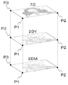
図19は、カモフラージュ画像データ作製ステップST5を示す模式図である。マゼンタ分解画像データ(2DM)、イエロー分解画像データ(2DY)及び隠ぺい用カモフラージュ画像データ(7D)は、共通する位置に基準点(P1、P2、P3)をそれぞれ有していることから、それぞれの基準点同士を重ね合わせた後、編集部(U2)において各画像を合成し、カモフラージュ画像データ(3D)を作製する。 FIG. 19 is a schematic diagram showing the camouflage image data creation step ST5. Since the magenta decomposed image data (2DM), the yellow decomposed image data (2DY), and the concealing camouflage image data (7D) have reference points (P1, P2, P3) at common positions, respectively. After superimposing the reference points, the images are combined in the editing unit (U2) to produce camouflage image data (3D).
図20(a)は、カモフラージュ画像データ(3D)を示す模式図であり、図20(b)は、潜像画像データ(6D)を示す模式図である。カモフラージュ画像データ(3D)は、シアン、マゼンタ及びイエローの色情報を有しているが、模様部(4’’)に相当する箇所のみ、シアンの色情報を有していない。 FIG. 20A is a schematic diagram showing camouflage image data (3D), and FIG. 20B is a schematic diagram showing latent image data (6D). The camouflage image data (3D) has color information of cyan, magenta, and yellow, but does not have cyan color information only in a portion corresponding to the pattern portion (4 ″).
一方、色設定潜像画像データ(6D’)は、シアンの色情報のみを有している。よって、カモフラージュ画像データ(3D)と色設定潜像画像データ(6D’)を積層して出力することで、色設定潜像画像データ(6D’)と模様部(4’’)が、シアン色を打ち消しあうことで、印刷模様(2’’)とした場合に、潜像画像(6’’)を、隠ぺいすることが可能となる。 On the other hand, the color setting latent image data (6D ′) has only cyan color information. Therefore, the camouflage image data (3D) and the color setting latent image data (6D ′) are stacked and output, so that the color setting latent image data (6D ′) and the pattern portion (4 ″) are cyan. By canceling, the latent image (6 ″) can be concealed when the printed pattern (2 ″) is used.
なお、前述のとおり、潜像画像(6’’)は、シアンに限らず、他の色とすることも可能である。例えば、マゼンタとした場合、カモフラージュ画像データ(3D)は、シアン、マゼンタ及びイエローの色情報を有しているが、模様部(4’’)に相当する箇所のみ、マゼンタの色情報を有していない。 Note that, as described above, the latent image (6 ″) is not limited to cyan, but may be other colors. For example, in the case of magenta, the camouflage image data (3D) has color information of cyan, magenta, and yellow, but only the portion corresponding to the pattern portion (4 ″) has magenta color information. Not.
一方、色設定潜像画像データ(6D’)は、マゼンタの色情報のみを有している。よって、カモフラージュ画像データ(3D)と色設定潜像画像データ(6D’)を積層して出力することで、色設定潜像画像データ(6D’)と模様部(4’’)が、マゼンタ色を打ち消しあうことで、印刷模様(2’’)とした場合に、潜像画像(6’’)を、隠ぺいすることが可能となる。 On the other hand, the color setting latent image data (6D ′) has only magenta color information. Therefore, the camouflage image data (3D) and the color setting latent image data (6D ′) are stacked and output, so that the color setting latent image data (6D ′) and the pattern portion (4 ″) are magenta. By canceling, the latent image (6 ″) can be concealed when the printed pattern (2 ″) is used.
次に、出力ステップST6として、印刷部(U4)において、ST4で作製した色設定潜像画像データ(6D’)と、ST5で作製したカモフラージュ画像データ(3D)を基に、基材(1)上に画像を形成する。 Next, as an output step ST6, in the printing unit (U4), based on the color setting latent image data (6D ′) created in ST4 and the camouflage image data (3D) created in ST5, the base material (1) Form an image on top.
基材(1)は、多孔質の体質顔料を主体とした塗布液を塗工することで形成されたインキ受理領域(Z)を少なくとも有するものを用いる。本発明では、インキ受理領域(Z)
に積層して印刷を施すことで生じる、インキの浸透性の差を利用することで、拡散反射光下と正反射光下で、画像をチェンジさせている。よって、基材(1)はインキ受理領域(Z)を有する必要がある。
As the substrate (1), a substrate having at least an ink receiving area (Z) formed by applying a coating liquid mainly composed of a porous extender pigment is used. In the present invention, the ink receiving area (Z)
The image is changed under diffuse reflection light and regular reflection light by utilizing the difference in the permeability of the ink that is generated by printing on the sheet. Therefore, the base material (1) needs to have an ink receiving area (Z).
なお、基材(1)がインキ受理領域(Z)を有していない場合には、出力ステップST6の前に、受理領域形成ステップST7として、印刷部(U4)により、基材(1)上の少なくとも一部の領域に、多孔質の体質顔料を主体とした塗布液を塗工した後、塗布液を乾燥させることで、インキ受理領域(Z)を形成する。 In addition, when the base material (1) does not have the ink receiving area (Z), the printing section (U4) performs the receiving area forming step ST7 on the base material (1) before the output step ST6. An ink receiving area (Z) is formed by applying a coating liquid mainly composed of a porous extender pigment to at least a part of the area, and then drying the coating liquid.
受理領域形成ステップST7を設けることで、基材(1)を限定することなく、印刷模様(2’’)を形成することが可能となる。 By providing the receiving region forming step ST7, it is possible to form the printed pattern (2 ″) without limiting the base material (1).
出力ステップST6は、まず、色設定潜像画像データ(6D’)を、基材(1)上にデジタル印刷方式により印刷し、潜像画像(6’’)を形成する。印刷方式は、インキ受理領域(Z)上に出力可能な印刷方式であれば特に限定されるものではない。 In the output step ST6, first, the color setting latent image data (6D ') is printed on the substrate (1) by a digital printing method to form a latent image (6 "). The printing method is not particularly limited as long as it is a printing method capable of outputting on the ink receiving area (Z).
次に、カモフラージュ画像データ(3D)を、潜像画像(6’’)と模様部(4’’)が同じ位置となるように、基材(1)に印刷した潜像画像(6’’)上に形成することで、印刷模様(2’’)が形成された媒体(S3)となる。 Next, the camouflage image data (3D) is a latent image (6 ″) printed on the substrate (1) so that the latent image (6 ″) and the pattern portion (4 ″) are in the same position. ) To form a medium (S3) on which a printed pattern (2 ″) is formed.
なお、印刷順序に限定はなく、カモフラージュ画像(3’’)を先に形成した後、その上に潜像画像(6’’)を形成しても良い。 The order of printing is not limited, and the camouflage image (3 ″) may be formed first, and then the latent image (6 ″) may be formed thereon.
また、色設定画像データ(6D’)とカモフラージュ画像データ(3D)の出力回数は、基材(1)上に印刷した、潜像画像(6’’)とカモフラージュ画像(3’’)の印刷回数に差があれば、特に印刷回数に限定はない。 The number of output times of the color setting image data (6D ′) and the camouflage image data (3D) is the number of times that the latent image (6 ″) and the camouflage image (3 ″) printed on the substrate (1) are printed. If there is a difference in the number of times, the number of times of printing is not particularly limited.
本発明の媒体(S3)の印刷方法は、オンデマンド印刷が好ましい。オンデマンド印刷で作製することにより、可視画像である印刷模様(2’’)と、観察角度の変化により視認可能となる潜像画像(6’’)を、媒体(S3)ごとに異なる画像として印刷することが可能となる。すなわち、印刷模様(2’’)及び潜像画像(6’’)を可変画像として扱うことが可能となる。 The printing method for the medium (S3) of the present invention is preferably on-demand printing. By producing by on-demand printing, the printed pattern (2 ″) that is a visible image and the latent image (6 ″) that can be visually recognized by changing the observation angle are different for each medium (S3). It becomes possible to print. In other words, the print pattern (2 ″) and the latent image (6 ″) can be handled as variable images.
なお、印刷模様(2’’)及び潜像画像(6’’)を可変画像として、媒体(S3)を作製する場合、画像データ取得ステップST1は、作製する複数の印刷模様データ(2D)、及び複数の潜像画像データ(6D)のうち、少なくとも一種類の画像データにおいて、少なくとも二つの異なる画像データを、入力部(U1)又は編集部(U2)で作製した後、記憶部(U3)に格納する。 When the medium (S3) is produced using the print pattern (2 ″) and the latent image (6 ″) as variable images, the image data acquisition step ST1 includes a plurality of print pattern data (2D) to be produced, And after producing at least two different image data in at least one kind of image data among a plurality of latent image data (6D) by the input unit (U1) or the editing unit (U2), the storage unit (U3) To store.
各画像を可変画像として、媒体(S3)を作製する場合、出力ステップST6の前に、画像データ取得ステップST1において、記憶部(U3)に格納した複数の画像データの中から、ユーザが可変画像とする所望の画像データを選択する、データ選択ステップST5.5をさらに有する。 When the medium (S3) is produced using each image as a variable image, the user can change the variable image from the plurality of image data stored in the storage unit (U3) in the image data acquisition step ST1 before the output step ST6. The data selection step ST5.5 is further selected for selecting desired image data.
出力ステップST6は、データ選択ステップST5.5で選択した所望の画像データを基に、各ステップにより作製した、カモフラージュ画像データ(3D)と色設定潜像画像データ(6D’)を、印刷部(U4)から、異なる画像データとして出力する。作製した複数の媒体(S3)は、所望の画像が可変情報として付与された媒体(S3)となる。 In the output step ST6, the camouflage image data (3D) and the color setting latent image data (6D ′) produced in each step based on the desired image data selected in the data selection step ST5.5 are printed in the printing unit ( From U4), it outputs as different image data. The plurality of produced media (S3) are media (S3) to which a desired image is given as variable information.
例えば、三つの媒体(S3)を作製し、カモフラージュ画像データ(3D)と色設定潜像画像データ(6D’)のうち、色設定潜像画像データ(6D’)を可変画像とする場合、画像データ取得ステップST1にて、五つの異なる画像データを、潜像画像データ(6D)として、入力部(U1)又は編集部(U2)で作製した後、記憶部(U3)に格納する。 For example, when three media (S3) are produced and the color setting latent image data (6D ′) is a variable image among the camouflage image data (3D) and the color setting latent image data (6D ′), In the data acquisition step ST1, five different image data are produced as latent image data (6D) by the input unit (U1) or the editing unit (U2), and then stored in the storage unit (U3).
次に、隠ぺい用カモフラージュ画像データ作製ステップST3、色設定ステップST4及びカモフラージュ画像データ作製ステップST5にて、五つの異なる潜像画像データ(6D)ごとに対応したカモフラージュ画像データ(3D)である、五つの異なるカモフラージュ画像データを編集部(U2)で作製した後、記憶部(U3)に格納する。 Next, the camouflage image data (3D) corresponding to each of the five different latent image data (6D) in the camouflage image data creation step ST3, the color setting step ST4, and the camouflage image data creation step ST5. Three different camouflage image data are created by the editing unit (U2) and then stored in the storage unit (U3).
また、五つの潜像画像データ(6D)においても、色設定ステップST4にて、前述の方法と同様に、色設定し、色設定潜像画像データ(6D’)を作製した後、記憶部(U3)に格納する。 Also, in the five latent image data (6D), in the color setting step ST4, colors are set and the color setting latent image data (6D ′) is created in the same manner as described above, and then the storage unit ( U3).
次に、データ選択ステップST5.5で、画像データ取得ステップST1にて記憶部(U3)に格納した五つの潜像画像データ(6D)の中から、ユーザが可変画像とする所望の潜像画像データ(6D)を三つと、選択した潜像画像データ(6D)を基に作製した、色設定潜像画像データ(6D’)及びカモフラージュ画像データ(3D)をそれぞれ三つ選択する。 Next, in the data selection step ST5.5, a desired latent image to be changed by the user from the five latent image data (6D) stored in the storage unit (U3) in the image data acquisition step ST1. Three pieces of data (6D) and three pieces of color setting latent image data (6D ′) and camouflage image data (3D) created based on the selected latent image data (6D) are selected.
最後に、出力ステップST6において、データ選択ステップST5.5で選択した三つの色設定潜像画像データ(6D’)及びカモフラージュ画像データ(3D)を、印刷部(U4)から、異なる画像データとして出力する。作製した三つの媒体(S3)は、可視画像である印刷模様(2’’)及び潜像画像(6’’)が、いずれも異なる画像(可変画像)として付与された媒体(S3)となる。 Finally, in the output step ST6, the three color setting latent image data (6D ′) and the camouflage image data (3D) selected in the data selection step ST5.5 are output as different image data from the printing unit (U4). To do. The produced three media (S3) are media (S3) to which a printed pattern (2 ″) and a latent image (6 ″), which are visible images, are all applied as different images (variable images). .
以上、本発明の媒体(S3)の作製方法は、複数の媒体(S3)を作製する際に、画像データ取得ステップST1で複数の画像データを作製し、隠ぺい用カモフラージュ画像データ作製ステップST3、色設定ステップST4及びカモフラージュ画像データ作製ステップにより、異なる画像データを作製した後、データ選択ステップST5.5及び出力ステップST6で、所望の画像データを選び印刷することで、簡易に、画像を可変要素として付与することが可能となる。 As described above, in the method for producing the medium (S3) of the present invention, when producing a plurality of media (S3), a plurality of image data is produced in the image data acquisition step ST1, and the concealing camouflage image data producing step ST3, color After creating different image data by the setting step ST4 and the camouflage image data creation step, the desired image data is selected and printed in the data selection step ST5.5 and the output step ST6, so that the image can be easily used as a variable element. It becomes possible to grant.
1 基材
2、2’、2’’ 印刷模様
3 カモフラージュ画像
3a カモフラージュ要素
4、4’、4’’ 模様部
5、5’、5’’ 背景部
6、6’、6’’ 潜像画像
6a 潜像要素
7 階調カモフラージュ部
S1、S2、S3 偽造防止媒体
Z インキ受理領域
M 作製装置
U1 入力部
U2 編集部
U3 記憶部
U4 印刷部
U5 通信インタフェース
U6 表示部
2D 印刷模様データ
2DC シアン分解画像データ
2DM マゼンタ分解画像データ
2DY イエロー分解画像データ
2DC’ 隠ぺい画像データ
3D カモフラージュ画像データ
6D 潜像画像データ
6D’ 色設定潜像画像データ
7D 隠ぺい用カモフラージュ画像データ
DESCRIPTION OF
Claims (6)
前記カモフラージュ画像は、前記基材と異なる色の模様部が少なくとも第1のインキで形成され、前記模様部の周囲に形成された背景部は、前記基材と異なる色の少なくとも第2のインキで形成され、
前記潜像画像は、前記模様部と同一形状、かつ、同じ大きさで前記背景部と毛抜き合わせで前記基材と異なる色の第3のインキで形成され、
拡散反射光下において、前記背景部は、積層して成る前記模様部及び前記潜像画像と等色であり、
正反射光下において、積層して成る前記潜像画像及び前記模様部と、前記背景部は、同一入射光に対する反射光の差により、前記潜像画像が視認されることを特徴とする偽造防止媒体。 An ink receiving area having a printed pattern of a color different from that of a base material formed by laminating a camouflage image and a latent image on at least a part of the base material;
In the camouflage image, a pattern portion having a color different from that of the substrate is formed with at least a first ink, and a background portion formed around the pattern portion is formed with at least a second ink having a color different from that of the substrate. Formed,
The latent image is formed with a third ink having the same shape and the same size as the pattern portion and a color different from that of the base material by tweezing with the background portion,
Under diffuse reflected light, the background portion is the same color as the patterned portion and the latent image formed by stacking,
Anti-counterfeiting characterized in that the latent image is visually recognized by the difference in reflected light with respect to the same incident light in the latent image and the pattern portion, which are laminated, and the background portion under regular reflection light. Medium.
前記模様部と前記背景部の間に、前記基材及び前記背景部と異なる色の少なくとも第4のインキで形成された階調カモフラージュ部が配置され、
前記模様部と前記潜像画像は、異なる色のインキで形成されたことを特徴とする請求項3記載の偽造防止媒体。 The printed pattern is a color gradation image, and the latent image is a gradation image;
Between the pattern portion and the background portion, a gradation camouflage portion formed of at least a fourth ink of a color different from the base material and the background portion is disposed,
4. The medium for preventing forgery according to claim 3, wherein the pattern portion and the latent image are formed of different color inks.
前記印刷模様の原画像である印刷模様データと、前記潜像画像の原画像である潜像画像データを作製する画像データ取得ステップと、
前記印刷模様データを色分解して複数の分解画像データを作製する色分解ステップと、
前記複数の分解画像データ及び前記潜像画像データに対し、共通する位置情報である位置座標を設定した後、前記複数の分解画像データのうち、前記潜像画像データを隠ぺいさせる隠ぺい分解画像データと前記潜像画像データを重ねて重複箇所を除去し、隠ぺい用カモフラージュ画像データを作製するステップと、
前記潜像画像データの色を、前記隠ぺい分解画像データと同じ色に設定し、色設定潜像画像データを作製するステップと、
前記隠ぺい用カモフラージュ画像データと、前記隠ぺい用カモフラージュ画像データを作製する際に用いなかった、残りの各分解画像データを合成し、カモフラージュ画像データを作製するステップと、
前記カモフラージュ画像データ及び前記色設定潜像画像データを積層して出力する出力ステップを備えることを特徴とする偽造防止媒体の作製方法。
A method for producing an anti-counterfeit medium according to claim 4,
Print pattern data that is an original image of the print pattern, and image data acquisition step of creating latent image data that is an original image of the latent image,
A color separation step for color-separating the print pattern data to create a plurality of pieces of separated image data;
After setting the position coordinates that are common position information for the plurality of decomposed image data and the latent image data, concealed decomposed image data for concealing the latent image image data among the plurality of decomposed image data and Superimposing the latent image data to remove the overlapping portion, creating concealing camouflage image data;
Setting the color of the latent image data to the same color as the concealment decomposed image data, and creating color setting latent image data;
Wherein a hiding for camouflage image data, was not used in making the hiding for camouflage image data, it synthesizes the each remaining separation image data, comprising the steps of producing a camouflage image data,
An anti-counterfeit medium manufacturing method comprising an output step of laminating and outputting the camouflage image data and the color setting latent image data.
Priority Applications (1)
| Application Number | Priority Date | Filing Date | Title |
|---|---|---|---|
| JP2014091133A JP6274663B2 (en) | 2014-04-25 | 2014-04-25 | Anti-counterfeit medium and method for producing the same |
Applications Claiming Priority (1)
| Application Number | Priority Date | Filing Date | Title |
|---|---|---|---|
| JP2014091133A JP6274663B2 (en) | 2014-04-25 | 2014-04-25 | Anti-counterfeit medium and method for producing the same |
Publications (2)
| Publication Number | Publication Date |
|---|---|
| JP2015208902A JP2015208902A (en) | 2015-11-24 |
| JP6274663B2 true JP6274663B2 (en) | 2018-02-07 |
Family
ID=54611526
Family Applications (1)
| Application Number | Title | Priority Date | Filing Date |
|---|---|---|---|
| JP2014091133A Active JP6274663B2 (en) | 2014-04-25 | 2014-04-25 | Anti-counterfeit medium and method for producing the same |
Country Status (1)
| Country | Link |
|---|---|
| JP (1) | JP6274663B2 (en) |
Families Citing this family (2)
| Publication number | Priority date | Publication date | Assignee | Title |
|---|---|---|---|---|
| JP6504564B2 (en) * | 2015-12-01 | 2019-04-24 | 独立行政法人 国立印刷局 | Anti-counterfeit printed matter |
| KR102205641B1 (en) * | 2019-07-02 | 2021-01-21 | 주식회사 광인사 | the improved color security printing method using UV fluorescent ink |
Family Cites Families (6)
| Publication number | Priority date | Publication date | Assignee | Title |
|---|---|---|---|---|
| JP4395598B2 (en) * | 2006-09-14 | 2010-01-13 | 独立行政法人 国立印刷局 | Authentic printed material |
| JP5409187B2 (en) * | 2009-08-17 | 2014-02-05 | キヤノン株式会社 | Image forming apparatus and image forming method |
| JP5245102B2 (en) * | 2009-11-25 | 2013-07-24 | 独立行政法人 国立印刷局 | Latent image printed matter |
| JP2011194632A (en) * | 2010-03-18 | 2011-10-06 | Mitsubishi Paper Mills Ltd | Forgery preventing printing method and forgery preventing printed matter |
| JP5799426B2 (en) * | 2011-10-27 | 2015-10-28 | 独立行政法人 国立印刷局 | Luminescent printed matter |
| JP5900820B2 (en) * | 2012-04-06 | 2016-04-06 | 独立行政法人 国立印刷局 | Latent image printed matter |
-
2014
- 2014-04-25 JP JP2014091133A patent/JP6274663B2/en active Active
Also Published As
| Publication number | Publication date |
|---|---|
| JP2015208902A (en) | 2015-11-24 |
Similar Documents
| Publication | Publication Date | Title |
|---|---|---|
| US8985634B2 (en) | Anti-counterfeit printed matter, method of manufacturing the same, and recording medium storing halftone dot data creation software | |
| CN1097945C (en) | Digital anti-counterfeiting software method and apparatus | |
| US9092872B2 (en) | System and method for creating an animation from a plurality of latent images encoded into a visible image | |
| US8792674B2 (en) | Method for encoding and simultaneously decoding images having multiple color components | |
| JP5732693B2 (en) | Method for producing halftone dot printed matter and recording medium storing software for producing halftone dot printed matter | |
| JP5971594B2 (en) | Method for producing anti-counterfeit formed body | |
| JP5799425B2 (en) | Printed material capable of authenticating authenticity, manufacturing apparatus and manufacturing method thereof, authentication apparatus for printed matter capable of authenticating authenticity and authentication method thereof | |
| JP5186655B2 (en) | Information carrier that can detect authenticity | |
| JP4649612B2 (en) | Authentic printed material | |
| JP6274663B2 (en) | Anti-counterfeit medium and method for producing the same | |
| JP4352168B2 (en) | Halftone image data authentication program, halftone print authentication system, and halftone image data authentication system | |
| JP2020089971A (en) | Anti-counterfeit printed matter, method of manufacturing data for anti-counterfeit printed matter, and manufacturing system for anti-counterfeit printed matter | |
| JP5768236B2 (en) | Anti-counterfeit printed matter, anti-counterfeit printed material preparation apparatus, and anti-counterfeit printed matter preparation method | |
| JP5709132B2 (en) | Printed material for preventing forgery, method for creating printed matter for preventing forgery, and system for creating printed matter for preventing forgery | |
| JP7284950B2 (en) | LATENT IMAGE PRINTED MATERIAL READING DEVICE, READING METHOD AND SOFTWARE FOR READING | |
| JP5990791B2 (en) | Anti-counterfeit printed matter | |
| JP6120080B2 (en) | Anti-counterfeit formed body and method of creating image data of anti-counterfeit formed body | |
| JP5099638B2 (en) | True / false discrimination printed matter | |
| JP2004181791A (en) | Printed matter with latent image-displaying body and its making apparatus | |
| JP4958117B2 (en) | Halftone data production apparatus and production program | |
| US10710394B2 (en) | Secure item comprising a revealing screen and a combined image | |
| JP5142143B2 (en) | How to create a halftone print | |
| EP2165844A2 (en) | Infrared printing with process printing inks | |
| JP7224588B2 (en) | Latent image pattern expression structure and method of creating data for phase modulation pattern | |
| JP2024017568A (en) | Latent image printed matter and its production method |
Legal Events
| Date | Code | Title | Description |
|---|---|---|---|
| A621 | Written request for application examination |
Free format text: JAPANESE INTERMEDIATE CODE: A621 Effective date: 20160907 |
|
| A977 | Report on retrieval |
Free format text: JAPANESE INTERMEDIATE CODE: A971007 Effective date: 20170824 |
|
| A131 | Notification of reasons for refusal |
Free format text: JAPANESE INTERMEDIATE CODE: A131 Effective date: 20170907 |
|
| A521 | Request for written amendment filed |
Free format text: JAPANESE INTERMEDIATE CODE: A523 Effective date: 20170926 |
|
| TRDD | Decision of grant or rejection written | ||
| A01 | Written decision to grant a patent or to grant a registration (utility model) |
Free format text: JAPANESE INTERMEDIATE CODE: A01 Effective date: 20171225 |
|
| A61 | First payment of annual fees (during grant procedure) |
Free format text: JAPANESE INTERMEDIATE CODE: A61 Effective date: 20180105 |
|
| R150 | Certificate of patent or registration of utility model |
Ref document number: 6274663 Country of ref document: JP Free format text: JAPANESE INTERMEDIATE CODE: R150 |
|
| R250 | Receipt of annual fees |
Free format text: JAPANESE INTERMEDIATE CODE: R250 |
|
| R250 | Receipt of annual fees |
Free format text: JAPANESE INTERMEDIATE CODE: R250 |
|
| R250 | Receipt of annual fees |
Free format text: JAPANESE INTERMEDIATE CODE: R250 |
|
| R250 | Receipt of annual fees |
Free format text: JAPANESE INTERMEDIATE CODE: R250 |