JP6263130B2 - Modulating light emitted by a lighting device using multiple different modulation periods - Google Patents
Modulating light emitted by a lighting device using multiple different modulation periods Download PDFInfo
- Publication number
- JP6263130B2 JP6263130B2 JP2014551717A JP2014551717A JP6263130B2 JP 6263130 B2 JP6263130 B2 JP 6263130B2 JP 2014551717 A JP2014551717 A JP 2014551717A JP 2014551717 A JP2014551717 A JP 2014551717A JP 6263130 B2 JP6263130 B2 JP 6263130B2
- Authority
- JP
- Japan
- Prior art keywords
- light
- modulation
- lighting device
- state
- lighting
- Prior art date
- Legal status (The legal status is an assumption and is not a legal conclusion. Google has not performed a legal analysis and makes no representation as to the accuracy of the status listed.)
- Active
Links
- 238000001514 detection method Methods 0.000 claims description 32
- 230000003287 optical effect Effects 0.000 claims description 32
- 238000005286 illumination Methods 0.000 claims description 22
- 238000001228 spectrum Methods 0.000 claims description 21
- 238000000034 method Methods 0.000 claims description 11
- 230000000694 effects Effects 0.000 claims description 7
- 230000000737 periodic effect Effects 0.000 claims description 7
- 230000008569 process Effects 0.000 claims description 7
- 206010044565 Tremor Diseases 0.000 description 15
- 238000005096 rolling process Methods 0.000 description 7
- 230000003252 repetitive effect Effects 0.000 description 6
- 238000004891 communication Methods 0.000 description 5
- 230000008901 benefit Effects 0.000 description 4
- 230000008859 change Effects 0.000 description 3
- 238000012545 processing Methods 0.000 description 3
- 230000004044 response Effects 0.000 description 3
- 206010008531 Chills Diseases 0.000 description 2
- 241000282412 Homo Species 0.000 description 2
- 238000013459 approach Methods 0.000 description 2
- 238000011161 development Methods 0.000 description 2
- 230000018109 developmental process Effects 0.000 description 2
- 238000010295 mobile communication Methods 0.000 description 2
- 238000009877 rendering Methods 0.000 description 2
- 230000003595 spectral effect Effects 0.000 description 2
- 230000009286 beneficial effect Effects 0.000 description 1
- 238000004590 computer program Methods 0.000 description 1
- 230000001419 dependent effect Effects 0.000 description 1
- 238000009826 distribution Methods 0.000 description 1
- 238000005516 engineering process Methods 0.000 description 1
- 238000009434 installation Methods 0.000 description 1
- 230000010354 integration Effects 0.000 description 1
- 230000002452 interceptive effect Effects 0.000 description 1
- 238000002372 labelling Methods 0.000 description 1
- 238000012986 modification Methods 0.000 description 1
- 230000004048 modification Effects 0.000 description 1
- 238000011084 recovery Methods 0.000 description 1
- 238000000926 separation method Methods 0.000 description 1
- 239000007787 solid Substances 0.000 description 1
- 230000001629 suppression Effects 0.000 description 1
- 230000002123 temporal effect Effects 0.000 description 1
Images


Classifications
-
- H—ELECTRICITY
- H05—ELECTRIC TECHNIQUES NOT OTHERWISE PROVIDED FOR
- H05B—ELECTRIC HEATING; ELECTRIC LIGHT SOURCES NOT OTHERWISE PROVIDED FOR; CIRCUIT ARRANGEMENTS FOR ELECTRIC LIGHT SOURCES, IN GENERAL
- H05B47/00—Circuit arrangements for operating light sources in general, i.e. where the type of light source is not relevant
- H05B47/10—Controlling the light source
- H05B47/175—Controlling the light source by remote control
- H05B47/19—Controlling the light source by remote control via wireless transmission
- H05B47/195—Controlling the light source by remote control via wireless transmission the transmission using visible or infrared light
-
- H—ELECTRICITY
- H04—ELECTRIC COMMUNICATION TECHNIQUE
- H04B—TRANSMISSION
- H04B10/00—Transmission systems employing electromagnetic waves other than radio-waves, e.g. infrared, visible or ultraviolet light, or employing corpuscular radiation, e.g. quantum communication
- H04B10/11—Arrangements specific to free-space transmission, i.e. transmission through air or vacuum
- H04B10/114—Indoor or close-range type systems
- H04B10/116—Visible light communication
-
- H—ELECTRICITY
- H05—ELECTRIC TECHNIQUES NOT OTHERWISE PROVIDED FOR
- H05B—ELECTRIC HEATING; ELECTRIC LIGHT SOURCES NOT OTHERWISE PROVIDED FOR; CIRCUIT ARRANGEMENTS FOR ELECTRIC LIGHT SOURCES, IN GENERAL
- H05B47/00—Circuit arrangements for operating light sources in general, i.e. where the type of light source is not relevant
- H05B47/10—Controlling the light source
Landscapes
- Engineering & Computer Science (AREA)
- Computer Networks & Wireless Communication (AREA)
- Physics & Mathematics (AREA)
- Electromagnetism (AREA)
- Signal Processing (AREA)
- Circuit Arrangement For Electric Light Sources In General (AREA)
- Optical Communication System (AREA)
- Selective Calling Equipment (AREA)
Description
本発明は、照明装置の分野に関し、より詳細には、照明システムにおける照明装置及びこれらに対応する方法に関する。 The present invention relates to the field of lighting devices, and more particularly to lighting devices in lighting systems and methods corresponding thereto.
これまでに増大している数の個々に制御可能な光源、高度なレンダリング能力を有する照明装置、照明器具及び照明アレンジメント等から成る統合された照明設備(installations)の出現は、専門家及び消費者市場の両方のための変化する照明システムと考えられることが可能である。このことは、完全な照明インフラストラクチャのレンダリング能力を十分に利用することができる直観的な制御に対する願望をもたらしている。幾つかの方法が、光源、照明装置、照明器具及び照明アレンジメント等を制御するために提案されている。 The emergence of integrated lighting installations consisting of an increasing number of individually controllable light sources, lighting equipment with advanced rendering capabilities, luminaires and lighting arrangements, etc. It can be considered a changing lighting system for both the market. This has created a desire for intuitive control that can fully utilize the rendering capabilities of a complete lighting infrastructure. Several methods have been proposed for controlling light sources, lighting devices, lighting fixtures, lighting arrangements, and the like.
光源の選択及び高度な制御のための光学的で自由な空間の通信(即ち可視光(VL)及び赤外線(IR)通信)が先だって提案されており、以下では、符号化された光(coded light:CL)と称される。一般に、符号化された光は、光源の高度な制御を可能にするように提案されている。符号化された光は、光源の光出力におけるデータの埋め込み(特に、見えない識別子)に基づいている。従って、符号化された光は、データ及び識別子を可視光源の光出力に埋め込むものとして規定されることができ、埋め込まれたデータ及び/又は識別子は、好ましくは、光源の主たる照明機能には影響しない。従って、データ及び/又は識別子に関する発された光の如何なる変調も、人間にはほぼ見えないものでなければならない。このことは、ネットワーク化された照明システムの対話型の場面設定、コミッショニング及び再コミッショニングのような用途を考慮に入れている。符号化された光は、符号化された照明システムの1つ以上の光源が符号化された光を発し、これにより情報を受信者に通信するように構成される通信用途において使用されることができる。 Optical free space communication (ie, visible light (VL) and infrared (IR) communication) for light source selection and advanced control has been previously proposed, and in the following, coded light (coded light). : CL). In general, encoded light has been proposed to allow a high degree of control of the light source. The encoded light is based on data embedding (particularly invisible identifiers) in the light output of the light source. Thus, the encoded light can be defined as embedding data and identifiers into the light output of the visible light source, and the embedded data and / or identifiers preferably affect the main lighting function of the light source. do not do. Therefore, any modulation of emitted light with respect to data and / or identifiers should be nearly invisible to humans. This allows for applications such as interactive scene setting, commissioning and recommissioning of networked lighting systems. The encoded light may be used in communication applications in which one or more light sources of the encoded illumination system emit encoded light, thereby communicating information to a recipient. it can.
光源、照明装置、照明器具及び照明アレンジメント等の制御のための1つの例は、位置及び制御の概念を含んでおり、この方法は、符号化された光の原理と、リモコンユニットが向けられて指し示めされている光源又は照明器具の符号を検出すると共に、これにより符号化された光を発する光源又は照明器具を識別するようにすることができるリモコンユニットとを活用する。このようなリモコンユニットは、典型的には、光源又は照明器具により発される符号化された光を検出する1つ以上のフォトダイオードを有する。代替的には、リモコンユニットは、符号化された光を検出するカメラを有することができる。位置及び制御の概念の1つの実施化は、固有の符号化された光信号を送信する光源又は照明器具を有することを含む。異なる光源又は照明器具が、異なる信号(即ち異なる埋め込まれた固有の識別子を有する信号)を送信する。この目的に適した信号の1つの例は、パルス幅変調(PWM)である。この位置及び制御の取り組みは、ユーザが単にリモコンユニットをこれに向けることによって、照明器具を選択することを可能にする手段として符号化された光を使用することの有利な点を示している。上述したように、この取組は、各照明器具の符号化された光のメッセージを検出するためにフォトダイオードを使用する。標準的なカメラによって、符号化された光を検出して復号化することが、提案されている。 One example for the control of light sources, lighting devices, luminaires, lighting arrangements, etc. includes the concept of position and control, which is directed to the principle of encoded light and a remote control unit. Utilizes a remote control unit that can detect the sign of the light source or luminaire being pointed to and thereby identify the light source or luminaire that emits the encoded light. Such remote control units typically have one or more photodiodes that detect the encoded light emitted by the light source or luminaire. Alternatively, the remote control unit can have a camera that detects the encoded light. One implementation of the position and control concept involves having a light source or luminaire that transmits a unique encoded light signal. Different light sources or luminaires transmit different signals (i.e. signals with different embedded unique identifiers). One example of a signal suitable for this purpose is pulse width modulation (PWM). This position and control approach shows the advantage of using the encoded light as a means to allow the user to select a luminaire simply by pointing the remote control unit at it. As mentioned above, this approach uses a photodiode to detect the encoded light message of each luminaire. It has been proposed to detect and decode the encoded light with a standard camera.
欧州特許出願第11159149.1号は、照明の光検出システムの光出力に埋め込まれているデータを検出するシステム及び方法に関する。当該光検出システムは、2次元画像の場面から出力される光を捕捉し、時間的にシフトされた線のインスタンスは、光サンプル時点として役立つ。画像の捕捉の過程における光検出手段上の連続的な列の捕捉間の時間的なシフトは、当該場面の最終的な捕捉された画像における変調された光源により照明される対象物の一部に対応する又は光源自体に対応する領域に関する画素値における線的な変化(line-wise variation)を生じさせる。画素値における線的な変化は、照明された対象物における画像の上に重ね合される水平線のパターンを構成する。符号化された光におけるメッセージ(即ち埋め込まれた符号)を復号化することは、変調された光源の元々の強度の変化と関連付けられている1次元(1D)信号の回復を必要とする。 European patent application 11159149.1 relates to a system and method for detecting data embedded in the light output of an illumination light detection system. The light detection system captures light output from the scene of the two-dimensional image, and the instance of the line shifted in time serves as the light sample time. The time shift between successive row captures on the light detection means in the process of image capture is part of the object illuminated by the modulated light source in the final captured image of the scene. It causes a line-wise variation in pixel values for the region corresponding to or corresponding to the light source itself. The linear change in pixel value constitutes a pattern of horizontal lines that are superimposed on the image of the illuminated object. Decoding a message in encoded light (ie, an embedded code) requires recovery of a one-dimensional (1D) signal that is associated with the original intensity change of the modulated light source.
記載される実施例の発明者らは、上述の概念による複数の不利な点を識別した。例えば、典型的には、(これらに限定されるわけではないが)移動通信装置(例えば、携帯電話、スマートフォン、タブレット・コンピュータ及びラップトップ・コンピュータ)のような携帯可能な電子装置に埋め込まれるカメラの基本的な限界は、符号化された光の検出を、常に信頼性の高いもの及び/又は再生可能なものにレンダリングするわけではない。 The inventors of the described embodiments have identified a number of disadvantages due to the concepts described above. For example, cameras that are typically embedded in portable electronic devices such as (but not limited to) mobile communication devices (eg, mobile phones, smartphones, tablet computers, and laptop computers). The basic limitation of this is that the detection of encoded light does not always render it reliable and / or reproducible.
本発明の目的は、これらの課題を解決し、照明装置により発される符号化された光が検出されないリスクが低減されるように配されている複数の照明装置を有している照明装置及び照明システムを提供することにある。 The object of the present invention is to solve these problems and to provide a lighting device having a plurality of lighting devices arranged to reduce the risk that encoded light emitted by the lighting device is not detected, and It is to provide a lighting system.
本発明の見地によれば、周期的な変調を有する光を発する光発光体と、指示子を光発光体に提供することによって光発光体を駆動する光ドライバとを有する照明装置であって、前記指示子は、前記光発光体により発される光の変調に関し、前記光発光体は、前記指示子に従って変調された光を発するように配されており、前記光ドライバは、複数の異なる変調期間を有する光を発するように前記光発光体を駆動するように配されている、照明装置が、提供される。 According to an aspect of the present invention, there is provided a lighting device including a light emitter that emits light having periodic modulation, and an optical driver that drives the light emitter by providing an indicator to the light emitter. The indicator relates to the modulation of light emitted by the light emitter, the light emitter is arranged to emit light modulated according to the indicator, and the light driver comprises a plurality of different modulations An illumination device is provided that is arranged to drive the light emitter to emit light having a period.
実施例において、光発光体は、画像捕捉ユニットにより検出されるべき光を発するように配されることができ、光ドライバは、変調期間のうちの少なくとも1つが画像捕捉ユニットの取得過程により生成される周波数ブライドスポット(blind spot)に対応するのを防止するように光発光体を駆動するように配されることができる。 In an embodiment, the light emitter can be arranged to emit light to be detected by the image capture unit, and the light driver is generated by the acquisition process of the image capture unit at least one of the modulation periods. It can be arranged to drive the light emitter so as to prevent it from responding to the frequency blind spot.
実施例において、光ドライバは、経時的に異なる変調期間の間で変化し得る。 In an embodiment, the optical driver may change between different modulation periods over time.
第1の実施例においては、変調された光を発する照明装置であって、指示子を前記照明装置の光発光体に提供するように配されている光ドライバであって、前記指示子は少なくとも2つの状態のうちの1つにおいて光発光体により発される光の変調に関し、前記光ドライバは、これにより光発光体を駆動する、光ドライバと、前記指示子に従って変調された光を発するように配された光発光体とを有する照明装置において、前記変調は各状態中に周期的であり、第1の状態において前記変調は期間T11を有し、第2の状態において前記変調は期間T12≠T11を有し、T11及びT12は、間隔[T10−ΔT1/2、T10+ΔT1/2]内の値をとり、ここでT10>0は時定数であり、ΔT1>0は、発された変調された光のこのような可視的なフリッカが防止されるように選択される時間オフセットである、照明装置を提供する。 In a first embodiment, an illumination device that emits modulated light, an optical driver arranged to provide an indicator to a light emitter of the illumination device, wherein the indicator is at least With respect to the modulation of light emitted by the light emitter in one of two states, the light driver thereby drives the light emitter and emits light modulated according to the light driver and the indicator. a lighting device having a light emitting element disposed on, the modulation is periodic in each state, the modulation in the first state has a duration T 11, the modulation in the second state the period has a T 12 ≠ T 11, T 11 and T 12 takes a value in the interval [T 10 -ΔT 1/2, T 10 + ΔT 1/2], where T 10> 0 is the time constant , [Delta] T 1> 0 is modulated emitted Is the time offset such visible flicker of the light is selected to be prevented, to provide a lighting device.
変調の周期が経時的に変化するので、第1の見地により配された照明装置は、発された変調された光が所与の固定された露出時間の設定において画像を捕捉している画像捕捉ユニットによって検出可能であることを可能にする。従って、有利には、このような照明装置は、圧延シャッタ・カメラ(rolling shutter camera)が、当該照明装置により発される変調された光に含まれる情報に対してブラインド(blind)であることを防止する。 Since the period of modulation changes over time, the illuminator arranged according to the first aspect captures an image with the emitted modulated light capturing an image at a given fixed exposure time setting. Allows being detectable by the unit. Thus, advantageously, such a lighting device provides that the rolling shutter camera is blind to the information contained in the modulated light emitted by the lighting device. To prevent.
第2の実施例によれば、第1の見地による照明装置をN個有する照明システムであって、各照明装置は、自身の固有の定数Ti(i=1…N)に関連付けられており、各照明装置に関する変調は、各状態中に周期的であり、第1の状態において光源iに関する前記変調は期間Ti1を有し、第2の状態において光源iに関する前記変調は期間Ti2≠Ti1を有し、Ti1及びTi2は、間隔[Ti0=ΔTi/2、Ti0+ΔTi/2]内の値をとり、ここでTi0>0は光源iに関する時定数であり、ΔTi>0は、発された変調された光における可視的なフリッカが回避されるように選択された光源iに関する時間オフセットである、照明システムが提供される。 According to the second embodiment, the lighting system has N lighting devices according to the first aspect, and each lighting device is associated with its own constant T i (i = 1... N). The modulation for each lighting device is periodic during each state, in the first state the modulation for light source i has a period T i1 , and in the second state the modulation for light source i has a period T i2 ≠ T i1 and T i1 and T i2 take values within the interval [T i0 = ΔT i / 2, T i0 + ΔT i / 2], where T i0 > 0 is the time constant for light source i , ΔT i > 0 is provided, the illumination system being a time offset for the selected light source i such that visible flicker in the emitted modulated light is avoided.
第3に、代替的な又は付加的な実施例において、前記光ドライバは、複数の異なる変調期間により変調される光を発するように光発光体を駆動するように配されることができる。 Third, in alternative or additional embodiments, the light driver can be arranged to drive a light emitter to emit light modulated by a plurality of different modulation periods.
実施例において、前記光発光体は、検出ユニットにより検出されるべき光を発するように配されることができ、少なくとも、前記変調期間の少なくとも1つが、他の変調期間の少なくとも1つの他のものが1つ以上のブライドスポットに対して検出スペクトル内のどこにあるかに関係なく、常に検出可能であるように、前記変調周波数は、少なくとも検出ユニットの検出範囲のブライドスポットの検出不可能な幅に対応している量だけ離間されることができる。 In an embodiment, the light emitter can be arranged to emit light to be detected by a detection unit, at least at least one of the modulation periods being at least one other of the other modulation periods So that it is always detectable regardless of where it is in the detection spectrum relative to one or more bride spots, the modulation frequency is at least the undetectable width of the bride spot in the detection range of the detection unit It can be separated by a corresponding amount.
実施例において、変調周波数は、人間の知覚可能な範囲内にある変調周波数の何れかの間において、内部変調効果を防止するように、離間されることが可能である。実施例において、変調周波数のうちの少なくとも1つは、変調周波数の少なくとも1つの他のものとの調和関係を有さない。 In an embodiment, the modulation frequencies can be spaced apart to prevent internal modulation effects between any of the modulation frequencies that are within human perceptible range. In an embodiment, at least one of the modulation frequencies does not have a harmonic relationship with at least one other of the modulation frequencies.
実施例において、複数の変調周波数は、前記光発光体の同じ光源により発されることができる。代替的には、光発光体は、同じ照明器具内の複数の光源を有し、複数の変調周波数の各々は、光源の対応するものにより発されることができる。 In embodiments, multiple modulation frequencies can be emitted by the same light source of the light emitter. Alternatively, the light emitter has multiple light sources within the same luminaire, and each of the multiple modulation frequencies can be emitted by a corresponding one of the light sources.
本発明は、添付の請求項において詳述される特徴の全てのあり得る組合せに関することに留意されたい。例えば、第1の見地の有利な点は第2の見地に当てはまり、第2の見地の有利な点は第1の見地に当てはまる。更に、第3の実施例は、第1又は第2の実施例と組み合されることができる。 It should be noted that the invention relates to all possible combinations of features detailed in the appended claims. For example, the advantages of the first viewpoint apply to the second viewpoint, and the advantages of the second viewpoint apply to the first viewpoint. Furthermore, the third embodiment can be combined with the first or second embodiment.
本発明の上述及び他の見地は、本発明の実施例を示している添付の図面を参照して、以下に詳細に記載される。 The foregoing and other aspects of the invention are described in detail below with reference to the accompanying drawings, which illustrate embodiments of the invention.
以下の実施例は、この開示が詳細で完全なものとなり、本発明の範囲を当業者に完全に伝達するように、一例として与えられる。同じ符号は、全体にわたって同じ要素を表している。以下の実施例において、開示される装置は、動作の状況において記載される。 The following examples are given by way of example so that this disclosure will be thorough and complete, and will fully convey the scope of the invention to those skilled in the art. The same reference number represents the same element throughout. In the following examples, the disclosed apparatus is described in the context of operation.
照明システムの動作は、ここで、図1の照明装置1を参照して開示される。図1の照明装置1は、符号2a、2b、2cを有する照明装置によって模式的に示されている、符号化された光を発するよう配されている少なくとも1つの照明装置を有する。少なくとも1つの照明装置2a、2b、2cは、照明器具であっても良く及び/又は照明制御システムの一部であっても良い。従って、照明システム1は、符号化された照明システムとして意味されることもある。図2を参照して更に開示されるように、照明装置2a、2b、2cは、少なくとも光ドライバ及び光発光体を有する。照明器具は、このような少なくとも1つの照明装置2a、2b、2cを有することができる。「照明装置」なる語は、部屋内の対象物を照らすためのために、部屋内の光を提供するために使用される装置を意味する。部屋と、この文脈において、典型的には、アパートの一室若しくはオフィスの一室、体育館、屋内の小売店、環境、劇場シーン、又は、例えば通りの一部のような、公共の場所又は屋外環境における空間である。矢印3a、3b、3cによって模式的に示されるように、各照明装置2a、2b、2cは、符号化された光を発することができる。従って、発された光は、情報系列を有している符号化された光に関連付けられている変調された部分を有する。この変調された光は、付加的な埋め込まれたデータを有する。例えば、データは、照明装置の固有の識別子を有することができる。発された光は、照明の寄与と関連付けられた変調されていない部分を有することもできる。各照明装置2a、2b、2cは、複数の光(又は照明)の設定、特に、発された光の色、色温度、強度及び周波数のような、照明装置の照明の寄与に関係する設定に関連付けられることが可能である。一般に、照明装置の照明の寄与は、照明装置2a、2b、2cにより発される光の時間平均化された出力として定義されることができる。図3は、周波数f=1/T0を有するベーストーン(base tone)を割り当てられている照明装置2a、2b、2cにより発される光信号3a、3b、3cを模式的に示している。このベーストーンは、周波数f=1/T0を有するパルス幅変調に従って発される。従って、得られる信号(トーン)は、パルスの単一の系列(train)である。複数の一次照明装置(multiprimary lighting devices)2a、2b、2c(例えば、別個のRGBチャネルを有するLED)に関して、得られる信号(トーン)は、パルス(一次色当たり1つ)の様々な系列と、全て同じベース周波数との線形結合である。図4は、図3の光信号の周波数表現のフーリエ変換の絶対値である、対応するスペクトル|H(f(z))|を示している。
The operation of the lighting system will now be disclosed with reference to the lighting device 1 of FIG. The illuminating device 1 of FIG. 1 has at least one illuminating device arranged to emit encoded light, schematically illustrated by an illuminating device having the
当該システム1は、システム1内の照明装置2a、2b、2cにより発される符号化された光を受信する及び検出するように配されたリモコンユニット4と称される装置を更に有する。リモコンユニット4は、複数の機能的なブロックに関して記載される。リモコンユニット4は、例えば、符号化された光を有する画像を捕捉することによって、システム1内の照明装置2a、2b、2cにより発される光を検出する画像センサを有する画像捕捉ユニット5を有する。近年の開発(例えば、欧州特許出願第11159149.1号により例示される)は、標準的なカメラの使用によって、符号化された光を検出するという可能性を示している。画像捕捉ユニット5は、カメラ(の一部)として実施化されることができる。リモコンユニット4は、画像捕捉ユニット5に動作可能なように結合されている処理ユニット6を更に有する。処理ユニット6は、画像捕捉ユニット5により捕捉される画像を分析し、捕捉された当該画像から、照明装置2a、2b、2cにより送信される符号化された光を識別する。リモコンユニット4は、処理ユニット6に動作可能に結合された送信器7を更に有する。送信器7は、符号8a及び8bで模式的に示されているように、照明装置2a、2b、2cと通信するように配されることができる。リモコンユニット4は、移動通信装置(例えば、携帯電話、多機能電話、錠剤コンピュータ又はラップトップ・コンピュータ)の一部でも良い。
The system 1 further comprises a device called a
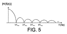
典型的には、画像捕捉ユニット5は、複数の種々の露出時間又はシャッタ速度の1つにおいて、画像を捕捉するように配される。固定露出時間Texpによって、画像捕捉ユニット5の取得過程は、取得した光信号に対するローパスフィルタ効果をもたらし、これによりローパスフィルタのカットオフ周波数(ヘルツ)がシャッタ速度値Texp(秒)により決定される。更に詳細には、照明装置2a、2b、2cからの光信号3a、3b、3cが画像捕捉ユニット5に到達する場合、画像捕捉ユニット5は、光信号3a、3b、3cを取得する。取得過程において、圧延シャッタは、画像捕捉ユニット5の画像センサの各線を時間Texpにわたって光にさらす。従って、この取得過程は、取得された光信号に対するローパスフィルタ効果を生成する。図5は、ローパスフィルタ特性|H(f(z))|を模式的に示しており、|H(f(z))|は、露出時間Texpによる圧延シャッタカメラを有する画像捕捉ユニット5の取得過程の周波数表現のフーリエ変換の絶対値である。従って、照明装置2a、2b、2cの1つ以上が、画像捕捉ユニット5のシャッタ速度のローパスフィルタ特性|H(f(z))|における零交差点(シャッタ速度値Texpの倍数に対応する)に対応する周波数で符号化された光を発する場合、画像捕捉ユニット5は、符号化された光を記録する又は記録することすらもできなくなり得る。即ち、 符号化された光の信頼性が高い検出を有するために、可視光通信に関する照明装置2a、2b、2cにより使用される信号の期間が、例えば、前記露出時間の倍数でないことが必要であり、さもなければ画像捕捉ユニット5がこれに「ブラインド」となる。
Typically, the image capture unit 5 is arranged to capture an image at one of a plurality of different exposure times or shutter speeds. Due to the fixed exposure time T exp , the acquisition process of the image capture unit 5 has a low-pass filter effect on the acquired optical signal, whereby the cutoff frequency (Hertz) of the low-pass filter is determined by the shutter speed value T exp (seconds). The More specifically, when the
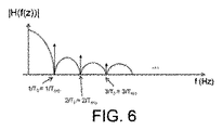
図5から、ブライドスポットの存在は、ローパスフィルタがゼロを有するf=1/Texpの倍数に対応することが明らかである。従って、ベース周波数f=1/T0=1/Texpを有するトーンは、図6において、スパイク「↑」で示されており、検知されなくなる。 From FIG. 5, it is clear that the presence of a bride spot corresponds to a multiple of f = 1 / T exp where the low pass filter has zero. Therefore, the tone having the base frequency f = 1 / T 0 = 1 / T exp is indicated by a spike “↑” in FIG. 6 and is not detected.
照明装置2a、2b、2cの更なる機能及び特性は、図2を更に参照して記載される。上述の課題を解決するために、照明装置2a、2b、2cは、期間が経時的に僅かに変化するトーンを有する符号化された光を発し、又は、言い換えると、照明装置2a、2b、2cは、経時的に『震える(shiver)』又は変動(fluctuate)する。各照明装置iは、N個の照明装置のシステムにおいて、i=1、…、Nであり、少なくとも2つのトーン間で震える。Ti1によって、照明装置iに関する震えトーン(shivering tone)のうちの一方が示され、Ti2によって、照明装置iに関して震えトーンのもう一方が示されている。従って、照明装置iに関してTi1≠Ti2である。照明装置iに関する発された変調された光のデータに埋め込まれる固有の識別子は、周波数f=1/Ti0により表されることができ、ここで、Ti0は、震えトーンがこの周りで変動するベーストーンのためのベース期間である。従って、Ti0≠Ti1≠Ti2である。
Further functions and characteristics of the
照明装置2a、2b、2cは、光ドライバ13を有する。照明装置2a、2b、2cも、光発光体14を有する。光ドライバ13は、光発光体14に指示子を供給するように配されている。指示子は、電気信号により供給される。代替的には、指示子は、機械的スイッチ又はリレーにより提供されることができる。指示子は、少なくとも2つの状態のうちの一方における光発光体14により発される光の変調に関する。従って、指示子は、現在の動作における光発光体14により発される光が、少なくとも2つの状態のうちのどの1つに従って発されるべきかを決定する。このことにより、光ドライバ13は、光発光体14を駆動するように配される。更に、光発光体14は、指示子に従って変調された光を発するように配されている。好ましくは、変調された光は、パルス幅変調を使用して送信される。
The
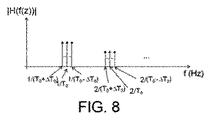
図7は、ベース周波数f=1/T0を有する震えトーンを発するように配された照明装置2a、2b、2cによって送られる光信号を示している(1つの照明装置のみが考えられる場合、添え字iは落とされることができ、即ちN=1に対してT10=T0)。得られるPWM光信号は、ベース期間T0周辺で変動する期間を有する。分かりやすさのために、単一の一次(光発光体14が白色LEDを有する)を有する照明装置2a、2b、2cに関して、得られる信号(トーン)は単一の系列のパルスである。複数の一次の照明装置2a、2b、2c(例えばRGB)の場合、得られる信号(震えトーン)は、パルスの様々な系列(一次につき1つ)と、全て同じベース周波数との、線型結合である。図8は、対応するスペクトル|H(f(z))|を示しており、|H(f(z))|は、図7の光信号の周波数表現のフーリエ変換の絶対値であり、各震えトーンがスパイク「↑」で示されている。
FIG. 7 shows the optical signal sent by the
図9において、得られる震えトーン(即ちスパイク「↑」)は、画像捕捉ユニット5のローパス特性と結合して示される。1/T0=1/Texpに関してさえ、震えトーンの一部は、ブライドスポットに落ちず、従って検出され得る。 In FIG. 9, the resulting tremor tone (ie spike “↑”) is shown combined with the low pass characteristic of the image capture unit 5. Even for 1 / T 0 = 1 / T exp , some of the tremor tones do not fall into the bridespot and can therefore be detected.
実施例において、各照明装置iに関してK個の震えトーンTi1、Ti2、…、TiKが存在する。従って、実際に、各照明装置iに関して、2つの状態だけでなく、K個の異なる震えトーンを表すK個の異なる状態が存在する。従って、この場合、各照明装置iに対する指示子は、K個の状態のうちの1つにおいて光発光体14により発される光の変調に関する。従って、このような場合、指示子は、現在の動作の光発光体14により発される光がK状態のどの状態に従って発されるべきかを決定する。 In an embodiment, there are K tremble tones T i1 , T i2 ,..., T iK for each lighting device i. Thus, in practice, for each lighting device i, there are not only two states, but K different states representing K different tremor tones. Thus, in this case, the indicator for each lighting device i relates to the modulation of the light emitted by the light emitter 14 in one of the K states. Thus, in such a case, the indicator determines which state of the K state the light emitted by the light emitter 14 of the current operation should be emitted.
各照明装置iは、時間オフセットΔTi及び公称期間Ti0と関連付けられている。好ましくは、各照明装置は、それ自身の公称期間を有する。即ち、i≠jに関してTi≠Tjである。更に、各照明装置は、自身の時間オフセットと関連付けられていても良い。即ち、i≠jに関してΔTi≠ΔTjである。このことは、種々の照明装置からの情報メッセージの検出及び受信を容易にすることができる。 Each lighting device i is associated with a time offset ΔT i and a nominal period T i0 . Preferably, each lighting device has its own nominal period. That is, T i ≠ Tj for i ≠ j. Furthermore, each lighting device may be associated with its own time offset. That is, ΔT i ≠ ΔTj for i ≠ j. This can facilitate the detection and reception of information messages from various lighting devices.
1つの照明装置のみを備えるシステムに関して、即ちN=1であり、第1の状態における変調は期間T11(第1の震えトーン)を有し、第2の状態における変調は期間T12≠T11(第2の震えトーン)を有し、T11及びT12は、間隔[T10−ΔT1/2、T10+ΔT1/2]内の値を取り、T10>0は時定数(1つの照明装置のための公称期間)であり、ΔT1>0は(1つの照明装置のための)時間オフセットである。2つのトーンT11及びT12のみが使用される場合、照明出力が対称であること、即ちT12>T11に関してT12−T10=T10−T11であることが有利であり得る。このことは、光発光体14の構造を単純化することができる。 For a system with only one illuminator, ie N = 1, the modulation in the first state has a period T 11 (first shaking tone) and the modulation in the second state has a period T 12 ≠ T 11 (second tremor tone) has, T 11 and T 12 has a value in the interval [T 10 -ΔT 1/2, T 10 + ΔT 1/2], T 10> 0 is the time constant ( ΔT 1 > 0 is the time offset (for one lighting device). If only two tones T 11 and T 12 are used, it may be advantageous that the illumination output is symmetrical, ie T 12 −T 10 = T 10 −T 11 for T 12 > T 11 . This can simplify the structure of the light emitter 14.
一般に、光発光体14により発される変調された光の可視的なフリッカが防止されるように、パラメータTi0及びΔTiの組合せが選択される。更に詳細には、間隔の下側の終点Ti0−ΔTi/2が或る周波数より高くあるように制限することは、可視光におけるフリッカを防止するために有益であり得る。間隔の上側の終点Ti0+ΔTi/2が或る周波数よりも低くあるように制限することは、当該信号を、ローパスフィルタの減衰が実際の状況においてあまりに激しい周波数表現の領域から遠ざけるのに有益であり得る。従って、光ドライバ13により提供された指示子は、現在の状態(即ち、どの震えトーンで、前記変調された光が発されなければならないか)に関する情報を含む。
In general, the combination of parameters T i0 and ΔT i is selected so that visible flicker of the modulated light emitted by the light emitter 14 is prevented. More specifically, limiting the lower endpoint T i0 −ΔT i / 2 of the interval to be above a certain frequency may be beneficial to prevent flicker in visible light. Limiting the upper endpoint T i0 + ΔT i / 2 of the interval to be lower than a certain frequency is useful to keep the signal away from the region of frequency representation where the attenuation of the low-pass filter is too severe in real situations. It can be. Thus, the indicator provided by the
例えば、期間Tiを有するベーストーンを割り当てられた照明装置iは、範囲[Ti0−ΔTi/2、Ti0+ΔTi/2]内で経時的に僅かに変化するトーンを送信する。従って、ΔTi>0によって、このことは、何らかの照明装置iトーンが何らかの公称期間Ti0においても発されることを防止する。従って、Ti0が、上述の開示された画像捕捉ユニット5のブライドスポットに対応することが可能になる。T10及びT20を2つの時間的に隣接する時定数として、T20>T10に関してΔTi0<<T20−T10を保持することは、異なる照明装置2a、2b、2cのトーン間の十分な分離を提供する。
For example, a lighting device i assigned a base tone having a period T i transmits a tone that varies slightly over time within the range [T i0 −ΔT i / 2, T i0 + ΔT i / 2]. Thus, with ΔT i > 0, this prevents any illuminator i tone from being emitted in any nominal period T i0 . Therefore, T i0 can correspond to the bride spot of the disclosed image capture unit 5 described above. Maintaining ΔT i0 << T 20 -T 10 for T 20 > T 10 , with T 10 and T 20 being two time-adjacent time constants, between the tones of
K個の異なる状態間の交番(alternation)は、種々の方法で決定されることができる。例えば、一実施例によれば、光ドライバ13は、K個の異なる状態間で変調を非周期的に交番させるように配される。例えば、他の実施例によれば、光ドライバ13は、所定の系列に従ってK個の異なる状態間で変調を交番させるように配される。前記変調は、確率変数に従ってK個の状態間で交番し得る。前記変調は、少なくとも2つの隣接するパルス幅変調期間における全く同一の状態に関連付けられていても良い。例えば、各照明装置2a、2b、2cは、PWM期間定数を、幾つかのPWM期間に等しい時間Tcに保持することができる。このことは、生成されたPWM信号は、十分に短い時間において観察される場合、一定の反復期間を有するように見えることを意味する。例えば、30Hzがビデオ・カメラのフレームレートであるならば、Tc=1/30Hzである。震えのパターンは、全ての照明装置2a、2b、2cに対して同じでも良く又は異なっていても良い。後者の場合、全ての照明装置2a、2b、2cは、異なるTcを有して、(常に上述の規定された範囲内において)異なるパターンに従って一方の反復期間からもう1つのものへまで飛ぶ(境界内の異なる期間へのジャンプ)。震えのパターンは、照明装置2a、2b、2cに予め割り当てられることもでき、又は照明装置2a、2b、2cにおいてランダムに生成されることもできる。
The alternation between the K different states can be determined in various ways. For example, according to one embodiment, the
当業者であれば、本発明が上述の好ましい実施例に決して限定されるものではないと理解するであろう。逆に、多くの変形及び変化が、添付の請求項の範囲内で可能である。例えば、開示されたリモコンユニット4と、少なくとも1つの照明装置2a、2b、2cを有していると共にリモコンユニット4によって制御可能である少なくとも1つの照明器具とは、アレンジメントとして設けられることが可能である。
Those skilled in the art will appreciate that the present invention by no means is limited to the preferred embodiments described above. On the contrary, many variations and modifications are possible within the scope of the appended claims. For example, the disclosed
上述で議論したように、近年の開発は、標準的なカメラを使用して符号化された光を検出するという可能性を示している。例えば、本発明は、圧延シャッタカメラを有する符号化された光の検出に適用可能である。圧延シャッタ・イメージ・センサにおいて、各後続の画像の列は、従来の列に対して小さい時間遅延を伴って取得される。結果として、高周波数の(high-frequent)時間的な光のフリッカは、横縞の空間パターンに変換される。後続の列が捕捉されるレートは、ラインレートflineと称される。殆どの画像センサのラインレートは比較的高い(典型的に10kHzを超える)ので、画像センサは、人間に感知されることができないように十分に高い光変調を捕捉することができる。 As discussed above, recent developments have shown the possibility of detecting encoded light using a standard camera. For example, the present invention is applicable to the detection of encoded light having a rolling shutter camera. In the rolling shutter image sensor, each subsequent image sequence is acquired with a small time delay relative to the conventional sequence. As a result, high-frequent temporal light flicker is converted into a horizontal stripe spatial pattern. The rate at which subsequent columns are captured is referred to as the line rate f line . Since the line rate of most image sensors is relatively high (typically above 10 kHz), the image sensor can capture sufficiently high light modulation so that it cannot be perceived by humans.
上述において、露出時間の値が、検出可能な周波数のスペクトルにおけるブライドスポットをどのように生じるかが示された。整数のサイクルが露出時間間隔に適合する如何なる周波数も、消えるように統合された光変調をもたらす。フーリエ領域において、これらのブラインド周波数スポットは、実際、光の統合が起こった(図5は、露出時間Texpによるsinc形の周波数応答の振幅を示している)矩形の時間窓のフーリエ変換であるsinc形の周波数応答と一致する。 In the above, it has been shown how the value of exposure time produces a bride spot in the detectable frequency spectrum. Any frequency where an integer number of cycles fits into the exposure time interval results in an integrated light modulation that disappears. In the Fourier domain, these blind frequency spots are actually a Fourier transform of a rectangular time window in which light integration has occurred (FIG. 5 shows the amplitude of a sinc shaped frequency response with exposure time T exp ). It matches the frequency response of the sinc type.
一般に、如何なる反復信号(例えば、繰り返されるデータパケット)も、基本的な周波数を有する調和信号と前記基本的な周波数の付加的な調和信号成分との合計によって特徴付けられることができる。このように、本発明は、一般的に反復信号に適応可能であり、パケット及び波形の両方に適応可能である。 In general, any repetitive signal (eg, a repeated data packet) can be characterized by the sum of a harmonic signal having a fundamental frequency and an additional harmonic signal component of the fundamental frequency. Thus, the present invention is generally adaptable to repetitive signals and can be adapted to both packets and waveforms.
殆どのモバイル装置に組み込まれたカメラは、カメラの露出値を固定するための選択肢を提供しない。結果として、瞬間的な露出時間によるスペクトルのブライドスポットのうちの1つがランプの周波数と一致する場合、カメラは符号化された光信号を検出することができない。一般に、反復信号に関して、カメラは、前記反復光信号と関連付けられている1つ以上の調和成分を検出することができなくなる。一般に、このことは、誤った検出又は信号検出の損失さえもたらす。 Cameras built into most mobile devices do not provide an option to fix the camera exposure value. As a result, the camera cannot detect the encoded light signal if one of the spectral bride spots due to the instantaneous exposure time matches the lamp frequency. In general, for repetitive signals, the camera will not be able to detect one or more harmonic components associated with the repetitive light signal. In general, this results in false detection or even loss of signal detection.
また、反復信号の1つ若しくは複数の周波数成分又はPWM信号変調周波数がスペクトルのブライドスポットに近い場合、この信号成分は完全には消されないが、適当な信号検出に対して依然として弱過ぎる。 Also, if one or more frequency components of the repetitive signal or the PWM signal modulation frequency is close to the spectral spot of the spectrum, this signal component is not completely extinguished but is still too weak for proper signal detection.
本開示において、変調された光を発する照明装置及びこのような少なくとも1つの照明装置を有する照明システムが、開示される。例えば、照明装置は、自身の発された変調された光が標準的な圧延シャッタ速度のカメラによって検出可能であるように配されることができる。こうするために、当該照明装置は、発された変調された光の周波数がベース(又は中心)周波数の周りで震えるように配されることができる。例えば、変調された光は、パルス幅変調を使用して送信されることができる。従って、この場合、得られるパルス幅変調光信号は、ベース期間の周りで変動する期間を有し、変調された光の震えを決定しているパラメータは、発された変調された光の可視フリッカが防止されるように、選択されることができる。 In the present disclosure, an illumination device that emits modulated light and an illumination system having at least one such illumination device are disclosed. For example, the illuminator can be arranged such that its emitted modulated light can be detected by a standard rolling shutter speed camera. To do this, the lighting device can be arranged such that the frequency of the emitted modulated light trembles around the base (or center) frequency. For example, modulated light can be transmitted using pulse width modulation. Thus, in this case, the resulting pulse width modulated optical signal has a period that varies around the base period, and the parameter that determines the tremor of the modulated light is the visible flicker of the emitted modulated light. Can be selected to be prevented.
しかしながら、本発明の範囲は、このような実施例に限定される必要はない。説明されたように、本発明は符号化された光が検知されなくなるというリスクを低減させることにある。このことは、複数K個の異なる変調周波数(Kは、少なくとも2であり、実施例においては2よりも大きい)によって、所与の照明装置から光を変調することにより達成される。上述の実施例において、異なる変調周波数は、「震え」のパターンにおける周波数を変化させることによって実施化されるが、変調が検出されないリスクを低減させる着想が、異なる変調周波数の何らかのアレンジメントによって実施化されることもできることが、本願明細書の開示において認識されて与えられる。以下では、代替的な実施例が記載され、複数の周波数成分が同時に生成されるように、好ましくは、何らかの所与の状況において、少なくとも1つの変調周波数が露出時間の何らかのブラインドスポットの外側に常に落ちるように(即ち全ての周波数がブラインドスポットと一致する状況はない)、前記光は変調される。 However, the scope of the present invention need not be limited to such examples. As explained, the present invention is to reduce the risk that encoded light will not be detected. This is accomplished by modulating light from a given illuminating device by a plurality of K different modulation frequencies (K is at least 2 and in an embodiment is greater than 2). In the above example, different modulation frequencies are implemented by changing the frequency in the “tremor” pattern, but the idea of reducing the risk that no modulation is detected is implemented by some arrangement of different modulation frequencies. It is recognized and provided in the disclosure herein. In the following, alternative embodiments are described, and preferably in some given situation, at least one modulation frequency is always outside some blind spot of exposure time so that multiple frequency components are generated simultaneously. The light is modulated so that it falls (i.e. there is no situation where all frequencies coincide with blind spots).
実施例において、反復信号は、2つの優位な周波数を含むように生成される。例えば、このような信号を生成する1つの仕方は、少なくとも2つの異なる信号(各々異なる優位な周波数を有する)を合計することである。図10及び11は、異なる周波数を有する異なる信号の合計により生成される、複数のあり得る周波数の配分の信号スペクトルを表している。例えば、共通にラベルを付された周波数成分の各々が、1つの単一光源に関連付けられており、例えば、(図1の符号を参照して)Aとラベルを付された成分は第1の光源2aからのものであり、Bとラベルを付された成分は第2の光源2bからのものであり、Cとラベルを付された成分は第3の光源2cからのものである。図10及び11の実施例において、信号Aの、両方の成分が検出可能であり、信号Bの低い方の周波数成分は失われ、信号Cの高い方の周波数成分は失われる。
In an embodiment, the repetitive signal is generated to include two dominant frequencies. For example, one way to generate such a signal is to sum at least two different signals, each having a different dominant frequency. FIGS. 10 and 11 represent the signal spectrum of a plurality of possible frequency distributions produced by the sum of different signals having different frequencies. For example, each of the commonly labeled frequency components is associated with one single light source, for example, the component labeled A (with reference to FIG. 1) is the first The component labeled B from the
図10は、ランプ当たり2つの隣接した周波数を使用している1つの実施例を示している。前記変調周波数は一緒に近いが、前記変調周波数のうちの少なくとも1つは、他のもののうちの少なくとも1つが1つ以上のブライドスポットに関連する検出スペクトルに落ちるにも関わらず常に検出可能であるように、前記変調周波数は十分に離間されている。即ち、2つの隣接する周波数に関して、これらは、近くないので両方ともブライドスポットに落ちることはない。ブラインドスポットの近くで、周波数は、この特定の露出時間Texpに関連付けられたsinc形の周波数応答の大きさに等しい抑制を受け、こうして、閾値は、sinc形の検出スペクトルのy軸に適用されることができ、この閾値よりも低く留まる各ブラインドスポットの周りの周波数範囲は、周波数に対する「禁制」ゾーンであると考えられることが可能である。従って、変調周波数間の最小限の間隔は、ブラインドスポットのノードの周りの或る窓に対応するように配されることができ、例えば、検出スペクトルの或る分率又はパーセンテージの高さにより定義される。例えば、所与のブラインドスポット(即ち1/Texpにおける1)の周りにおいて、符号化された光信号のみが検出可能であり、検出スペクトルは、或る閾値の高さ(例えば、受信電力に関する最大の或るパーセンテージ)よりも高い場合、変調周波数間の間隔は、少なくとも前記検出スペクトルにおける0ノードの周波数の位置からこの最小限の検出閾値に対応する周波数位置までの距離である。そのように、変調周波数のうちの1つが厳密にブラインドスポットの中心(ノード)に落ちる場合でさえも、他の変調周波数は、依然として最小の検出閾値に対応する検出スペクトルの周波数位置に落ちる。特定の検出閾値は、問題とされる装置に依存し得る。 FIG. 10 shows one embodiment using two adjacent frequencies per lamp. Although the modulation frequencies are close together, at least one of the modulation frequencies is always detectable even though at least one of the others falls into a detection spectrum associated with one or more bride spots. Thus, the modulation frequencies are sufficiently separated. That is, for two adjacent frequencies, they are not close so both will not fall into the bride spot. Near the blind spot, the frequency is subject to a suppression equal to the magnitude of the sinc shaped frequency response associated with this particular exposure time T exp , and thus the threshold is applied to the y axis of the sinc shaped detection spectrum. The frequency range around each blind spot that stays below this threshold can be considered a “forbidden” zone for frequency. Thus, the minimum spacing between modulation frequencies can be arranged to correspond to a certain window around the blind spot node, eg defined by a certain fraction or percentage height of the detected spectrum. Is done. For example, only a coded optical signal can be detected around a given blind spot (ie 1 at 1 / T exp ), and the detection spectrum has a certain threshold height (eg maximum for received power). The spacing between modulation frequencies is at least the distance from the position of the zero node frequency in the detection spectrum to the frequency position corresponding to this minimum detection threshold. As such, even if one of the modulation frequencies falls strictly to the center (node) of the blind spot, the other modulation frequency still falls to the frequency position of the detection spectrum corresponding to the minimum detection threshold. The particular detection threshold may depend on the device in question.
このような実施例は、潜在的に検出アルゴリズムに有益である。しかしながら、実際、光生成における如何なる非線形性も、人間の知覚可能な範囲に入る1つ以上の付加的な、低い周波数信号成分をもたらし得る。このような(望まれない)低周波数成分は相互変調の効果に起因するものであり、2つ(意図的な)信号成分が一緒に近すぎるものである場合に生じ得る。従って、実施例において、前記変調は、この効果を防止するために、少なくとも如何なる相互変調周波数も人間の知覚可能な範囲外に落ちるように、広く離間された周波数成分により生成されことができる。より広く間隔を置かれた変調周波数の例は、図11に模式的に示されている。 Such an embodiment is potentially useful for detection algorithms. In fact, however, any nonlinearity in light generation can result in one or more additional, low frequency signal components that fall within the human perceptible range. Such (unwanted) low frequency components are due to the effects of intermodulation and can occur when two (intentional) signal components are too close together. Thus, in an embodiment, the modulation can be generated by widely spaced frequency components so that at least any intermodulation frequency falls outside the human perceptible range to prevent this effect. An example of more widely spaced modulation frequencies is schematically illustrated in FIG.
2つ(以上の)変調周波数が離間されている場合、これらは同じブラインドスポットに落ちないが、計画なしに、異なるブラインドスポットに落ちるという可能性がある。例えば、1つが1/Texpにおけるノードに落ち、1つが2/Texp又は3/Texp等における次のノードに落ちるかもしれなかった。こうして、複数のブラインドスポットに当たるリスクを低減するために、実施例において、2つの(以上の)周波数成分は調和関係を有さないように、少なくとも一方がもう一方の整数倍でないように生成される。実施例において、一方は、もう一方の半整数倍でもない。更なる実施例において、nを整数として、一方は、他方のn/3倍ではなく及び/又は他方のn/4倍ではない等である。一般に、一方の周波数は、他方のn/mでないようにされることができ、ここで、分母mは、整数であると共に当該分母に対する閾値よりも小さい(効果的には、当該関係が不合理であるか調和的であるかの最小限の程度が設けられる)。 If two (or more) modulation frequencies are separated, they do not fall into the same blind spot, but may fall into different blind spots without planning. For example, one might fall to a node at 1 / T exp and one might fall to the next node, such as 2 / T exp or 3 / T exp . Thus, in order to reduce the risk of hitting multiple blind spots, in an embodiment, two (or more) frequency components are generated such that at least one is not an integer multiple of the other so that they do not have a harmonic relationship. . In an embodiment, one is not a half integer multiple of the other. In further embodiments, where n is an integer, one is not n / 3 times the other and / or not n / 4 times the other, etc. In general, one frequency can be made not to be n / m of the other, where the denominator m is an integer and smaller than the threshold for that denominator (effectively the relationship is irrational Or a minimum degree of harmony).
上述したように、複数の信号成分を生成する1つの方法は、当該成分を合計し、単一の基本光源(例えば、単一の電球)を駆動するために合計された信号を使用することである。単一の照明器具から複数の信号成分を生成するための代替的な実施例は、同じ照明器具内に収納される又は集積される異なる基本光源を使用することであって、例えば、複数のLEDを使用し、再び同じ制約を有して当該照明器具内の異なるLEDに対し異なる信号を割り当てることである。 As mentioned above, one way to generate multiple signal components is to sum the components and use the summed signal to drive a single basic light source (eg, a single bulb). is there. An alternative embodiment for generating multiple signal components from a single luminaire is to use different basic light sources housed or integrated within the same luminaire, e.g., multiple LEDs And assigning different signals to different LEDs in the luminaire again with the same constraints.
また、上述の実施例は単に例として記載されているのみであることは言うまでもない。例えば、本発明は、広範囲にわたるアプリケーションに適用可能であり、例えば、スマートフォン及びタブレット・コンピュータのような、カメラ・ベースの装置による符号化された光の検出、(例えば、消費者及び専門家の領域の光設備に関する)カメラ・ベースの符号化された光の検出、パーソナライズされた光制御、光ベースの対象物の標識化、及び光ベースの屋内のナビゲーションに適用可能である。 Needless to say, the above-described embodiments are merely described as examples. For example, the present invention is applicable to a wide range of applications, eg, detection of encoded light by camera-based devices, such as smartphones and tablet computers (eg, consumer and professional domains). Applicable for camera-based encoded light detection (for light fixtures), personalized light control, light-based object labeling, and light-based indoor navigation.
本発明は、リモコン又は1つ若しくは複数の照明装置を制御する制御システムに関する使用に限定されるものではない。他の実施例において、本願明細書において開示される符号化された光技術は、(例えば、制御ループの一部としてというよりもむしろ照明装置から捕捉ユニットまでの1つの検出のみにおいて)何らかの状況における情報を何らかの適切な捕捉ユニットに提供するために、又はマスター/スレーブ制御の関係以外の何らかの他の基礎に基づいて情報を交換するために使用されることができる。 The present invention is not limited to use with a remote control or a control system that controls one or more lighting devices. In other embodiments, the encoded light techniques disclosed herein can be used in some situations (eg, only in one detection from the illuminator to the acquisition unit rather than as part of a control loop). It can be used to provide information to any suitable acquisition unit, or to exchange information based on some other basis other than the master / slave control relationship.
更に、本発明の適用性は、圧延シャッタ技術による、何らかの特定のフィルタ効果若しくは検出スペクトルにおけるブラインドスポットによるブラインドスポットの回避に限定されるものではない。異なる変調周波数の使用は、変調された光を検出するために使用されている何らかの検出装置の何らかの副作用又は限定から生じる周波数ブラインドスポットのために検出されなくなる変調のリスクを低減させることが理解されるであろう。 Furthermore, the applicability of the present invention is not limited to the avoidance of blind spots by some specific filter effect or blind spots in the detection spectrum by rolling shutter technology. It will be appreciated that the use of different modulation frequencies reduces the risk of modulation becoming undetectable due to frequency blind spots resulting from some side-effect or limitation of any detection device used to detect the modulated light. Will.
実施例において、本発明は、時間変化する変調周波数又は同時変調周波数の使用に限定されるものではない。実施例において、照明装置は、2つ以上の異なる状態間を交番することができ、前記状態の少なくとも一方(及び潜在的には幾つか又は全て)は、異な周波数を有する2つの同時変調成分を使用する。 In an embodiment, the present invention is not limited to the use of time-varying modulation frequencies or simultaneous modulation frequencies. In an embodiment, the lighting device can alternate between two or more different states, at least one of the states (and potentially some or all) having two simultaneously modulated components having different frequencies. use.
更に、上述は変調周波数の観点において記載されたが、このことは変調期間の観点において同等に表現されることができ、また、変調期間の観点において記載されても、周波数の観点において同等に記載されることができることが分かるであろう。 Further, although the above has been described in terms of modulation frequency, this can be expressed equally in terms of modulation period, and even if described in terms of modulation period, it is equally described in terms of frequency. It will be appreciated that can be done.
更に、本発明は、ベーストーンに関して対称な上限及び下限+/―ΔTi/2に限定されるものではない。他の実施例において、窓は公称ベーストーンに関して非対称であっても良く、及び/又は以下のようにベーストーンよりも高い同じ数の変調周波数が存在する必要もない。実際、実施例において、何らかの1つの変調周波数が中心又は「ベース」トーンであるとして選出されることは、必要でない。 Further, the present invention is not limited to upper and lower limits +/− ΔT i / 2 that are symmetric with respect to the base tone. In other embodiments, the window may be asymmetric with respect to the nominal base tone and / or the same number of modulation frequencies above the base tone need not be present as follows. In fact, in an embodiment, it is not necessary that any one modulation frequency be elected as being the center or “base” tone.
開示されている実施例に対する他の変化は、添付図面、本明細書及び添付請求項の熟慮により、添付の請求項に記載の本発明を実施する際に当業者により理解され、行われることができる。請求項において、「有する」なる語は他の要素又はステップを排除するものではなく、単数形は複数形を排除するものではない。単一のプロセッサ又は他のユニットが、請求項に列挙されている幾つかの項目の機能を果たしても良い。特定の手段が、相互に異なる従属請求項において引用されているという単なる事実は、これらの手段の組み合わせが有利になるように使用されることができないと示すものではない。コンピュータプログラムは、一緒に供給される固体状態媒体又は光学記憶媒体のような、適切な媒体上に又は他のハードウェアの一部として記憶される/配布されることができるが、例えば、インターネット又は他の有線若しくは無線通信システムのような、他の形で配布されても良い。請求項における符号は、特許請求の範囲を限定するものとみなされてはならない。 Other changes to the disclosed embodiments may be understood and made by those skilled in the art in practicing the invention as set forth in the appended claims, upon careful consideration of the accompanying drawings, the specification and the appended claims. it can. In the claims, the word “comprising” does not exclude other elements or steps, and the singular does not exclude the plural. A single processor or other unit may fulfill the functions of several items recited in the claims. The mere fact that certain measures are recited in mutually different dependent claims does not indicate that a combination of these measures cannot be used to advantage. The computer program can be stored / distributed on suitable media, such as a solid state medium or optical storage media supplied together, or as part of other hardware, e.g. the Internet or It may be distributed in other forms, such as other wired or wireless communication systems. Any reference signs in the claims should not be construed as limiting the scope.
Claims (23)
指示子を前記光発光体に供給することによって前記光発光体を駆動する光ドライバであって、前記指示子は前記光発光体により発される光の変調に関し、前記光発光体は、前記指示子に従って変調された光を発するように配されている、光ドライバと、
を有する照明装置において、前記光ドライバは、同じ情報が複数の異なる変調期間において複数回埋め込まれる光を発するように前記光発光体を駆動する、照明装置。 A light emitter that emits light having a periodic modulation, wherein the periodic modulation embeds information in the light;
An optical driver for driving the light emitter by supplying an indicator to the light emitter, the indicator relating to modulation of light emitted by the light emitter, wherein the light emitter is the indicator An optical driver arranged to emit light modulated according to the child;
A lighting device having the light driver, the emitters driven to emit multiple embedded Ru light in the same information modulation period a plurality of different lighting devices.
前記光ドライバは、前記変調期間の少なくとも1つが、前記画像捕捉ユニットの取得過程により生成される周波数ブラインドスポットに対応するのを回避するように、前記光発光体を駆動する、
請求項1に記載の照明装置。 The light emitter emits light detected by an image capture unit;
The light driver drives the light emitter to avoid at least one of the modulation periods corresponding to a frequency blind spot generated by an acquisition process of the image capture unit;
The lighting device according to claim 1.
第1の状態において、前記変調は期間T11を有し、第2の状態において、前記変調は期間T12≠T11を有し、T11及びT12は、間隔[T10−ΔT1/2、T10+ΔT1/2]内の値をとり、T10>0は時定数であり、ΔT1>0は、発された変調された光における可視的なフリッカが回避されるように選択された時間オフセットである、請求項1乃至7の何れか一項に記載の照明装置。 The light driver drives the light emitter in at least two different states in which the modulation is periodic within each state;
In the first state, the modulation has a period T 11 , and in the second state, the modulation has a period T 12 ≠ T 11 , and T 11 and T 12 have an interval [T 10 −ΔT 1 / 2, T 10 + ΔT 1/ 2] takes a value in, T 10> 0 is the time constant, chosen to [Delta] T 1> 0 is visible flicker in the emitted modulated light is avoided The lighting device according to claim 1, wherein the time offset is a set time offset.
複数の変調期間の少なくとも1つが、他の前記変調期間の少なくとも1つの他のものが1つ以上のブラインドスポットに対して検出スペクトル内に落ちるにもかかわらず、常に検出可能であるように、複数の変調周波数は、前記検出ユニットの検出スペクトルのブラインドスポットの検出不可能な幅に少なくとも対応している量だけ離間されている、
請求項14に記載の照明装置。 The light emitter emits light detected by a detection unit;
At least one of the plurality of modulation periods, despite the fall in the detection spectrum with respect to at least one other of one or more blind spots of other of said modulation period, so as to always be detectable, double The number of modulation frequencies are separated by an amount corresponding at least to the undetectable width of the blind spot of the detection spectrum of the detection unit;
The lighting device according to claim 14.
Ti0>0は光源iに関する時定数であり、ΔTi>0は発された変調された前記光の可視的なフリッカが回避されるように選択された光源iに関する時間オフセットである、照明システム。 20. A lighting system comprising a plurality of N lighting devices according to any one of the preceding claims, wherein each lighting device is associated with its own constant T i , i = 1,. The modulation for each lighting device is periodic within each state, the modulation for light source i in the first state has a period T i1 , and the modulation for light source i in the second state is a period T i. have i2 ≠ T i1, T i1 and T i2, the interval - a value of the [T i0 ΔT i / 2, T i0 + ΔT i / 2],
T i0 > 0 is the time constant for light source i and ΔT i > 0 is the time offset for light source i selected so that visible flicker of the emitted modulated light is avoided. .
Applications Claiming Priority (5)
| Application Number | Priority Date | Filing Date | Title |
|---|---|---|---|
| US201261587298P | 2012-01-17 | 2012-01-17 | |
| US61/587,298 | 2012-01-17 | ||
| US201261599459P | 2012-02-16 | 2012-02-16 | |
| US61/599,459 | 2012-02-16 | ||
| PCT/IB2013/050326 WO2013108167A1 (en) | 2012-01-17 | 2013-01-14 | Modulation of light emitted by a lighting device, using plurality of different modulation periods |
Publications (3)
| Publication Number | Publication Date |
|---|---|
| JP2015509324A JP2015509324A (en) | 2015-03-26 |
| JP2015509324A5 JP2015509324A5 (en) | 2016-03-10 |
| JP6263130B2 true JP6263130B2 (en) | 2018-01-17 |
Family
ID=47827391
Family Applications (2)
| Application Number | Title | Priority Date | Filing Date |
|---|---|---|---|
| JP2014551716A Active JP6125535B2 (en) | 2012-01-17 | 2013-01-14 | Visible light communication |
| JP2014551717A Active JP6263130B2 (en) | 2012-01-17 | 2013-01-14 | Modulating light emitted by a lighting device using multiple different modulation periods |
Family Applications Before (1)
| Application Number | Title | Priority Date | Filing Date |
|---|---|---|---|
| JP2014551716A Active JP6125535B2 (en) | 2012-01-17 | 2013-01-14 | Visible light communication |
Country Status (7)
| Country | Link |
|---|---|
| US (2) | US9386643B2 (en) |
| EP (2) | EP2805586B1 (en) |
| JP (2) | JP6125535B2 (en) |
| CN (2) | CN104041190B (en) |
| ES (1) | ES2659037T3 (en) |
| RU (1) | RU2628570C2 (en) |
| WO (2) | WO2013108167A1 (en) |
Families Citing this family (71)
| Publication number | Priority date | Publication date | Assignee | Title |
|---|---|---|---|---|
| CN103365032B (en) * | 2012-03-28 | 2017-06-06 | 鸿富锦精密工业(深圳)有限公司 | Light source channel correcting method and system |
| US9374875B2 (en) * | 2012-09-12 | 2016-06-21 | Ariel-University Research And Development Company Ltd. | Light fixture connectable device useful for establishing a network infrastructure |
| DE102013014536B4 (en) | 2013-09-03 | 2015-07-09 | Sew-Eurodrive Gmbh & Co Kg | Method for transmitting information and apparatus for carrying out the method |
| WO2015039037A2 (en) | 2013-09-13 | 2015-03-19 | Cooper Technologies Company | Artificial light source based messaging platform |
| ITTO20130818A1 (en) * | 2013-10-10 | 2015-04-11 | Neodelis S R L | INTELLIGENT LIGHTING DEVICE, AND RELATED METHOD AND SYSTEM |
| JP6382970B2 (en) * | 2013-10-24 | 2018-08-29 | フィリップス ライティング ホールディング ビー ヴィ | Installable lighting control device |
| US9419716B2 (en) * | 2013-11-14 | 2016-08-16 | Nicolas Thomas Mathieu Dupont | Variable color data transmission |
| US10028277B2 (en) | 2013-11-20 | 2018-07-17 | Cyborg Inc. | Variable frequency data transmission |
| US9756706B2 (en) * | 2014-03-25 | 2017-09-05 | Osram Sylvania Inc. | Controlling a system that includes light-based communication (LCom)-enabled luminaires |
| JP6545192B2 (en) * | 2014-05-12 | 2019-07-17 | シグニファイ ホールディング ビー ヴィ | Verification of captured images using timestamps decoded from illumination from modulated light sources |
| WO2015173015A1 (en) * | 2014-05-12 | 2015-11-19 | Koninklijke Philips N.V. | Detection of coded light |
| US9711146B1 (en) | 2014-06-05 | 2017-07-18 | ProSports Technologies, LLC | Wireless system for social media management |
| US10592924B1 (en) | 2014-06-05 | 2020-03-17 | ProSports Technologies, LLC | Managing third party interactions with venue communications |
| US10290067B1 (en) | 2014-06-05 | 2019-05-14 | ProSports Technologies, LLC | Wireless concession delivery |
| US9648452B1 (en) | 2014-06-05 | 2017-05-09 | ProSports Technologies, LLC | Wireless communication driven by object tracking |
| US9635506B1 (en) | 2014-06-05 | 2017-04-25 | ProSports Technologies, LLC | Zone based wireless player communications |
| US10009100B2 (en) | 2014-06-18 | 2018-06-26 | Qualcomm Incorporated | Transmission of identifiers using visible light communication |
| NL1040869B1 (en) * | 2014-06-27 | 2016-06-08 | Eldolab Holding Bv | A method for driving a light source, a driver system to drive a light source and a luminaire comprising said light source and driver system. |
| CN104092953B (en) | 2014-07-10 | 2018-09-04 | 北京智谷睿拓技术服务有限公司 | Dimming controlling method and device and equipment with camera function |
| US9724588B1 (en) | 2014-07-11 | 2017-08-08 | ProSports Technologies, LLC | Player hit system |
| US9655027B1 (en) | 2014-07-11 | 2017-05-16 | ProSports Technologies, LLC | Event data transmission to eventgoer devices |
| US9760572B1 (en) | 2014-07-11 | 2017-09-12 | ProSports Technologies, LLC | Event-based content collection for network-based distribution |
| US9502018B2 (en) | 2014-07-11 | 2016-11-22 | ProSports Technologies, LLC | Whistle play stopper |
| WO2016007967A1 (en) | 2014-07-11 | 2016-01-14 | ProSports Technologies, LLC | Ball tracker snippets |
| US10572902B2 (en) | 2014-07-11 | 2020-02-25 | ProSports Technologies, LLC | Camera-based digital content distribution |
| US9343066B1 (en) | 2014-07-11 | 2016-05-17 | ProSports Technologies, LLC | Social network system |
| US9398213B1 (en) | 2014-07-11 | 2016-07-19 | ProSports Technologies, LLC | Smart field goal detector |
| US9591336B2 (en) | 2014-07-11 | 2017-03-07 | ProSports Technologies, LLC | Camera feed distribution from event venue virtual seat cameras |
| WO2016007965A1 (en) | 2014-07-11 | 2016-01-14 | ProSports Technologies, LLC | Ball tracker camera |
| US9965938B1 (en) | 2014-07-11 | 2018-05-08 | ProSports Technologies, LLC | Restroom queue management |
| US9305441B1 (en) | 2014-07-11 | 2016-04-05 | ProSports Technologies, LLC | Sensor experience shirt |
| WO2016007969A1 (en) | 2014-07-11 | 2016-01-14 | ProSports Technologies, LLC | Playbook processor |
| US9474933B1 (en) | 2014-07-11 | 2016-10-25 | ProSports Technologies, LLC | Professional workout simulator |
| US9729644B1 (en) | 2014-07-28 | 2017-08-08 | ProSports Technologies, LLC | Event and fantasy league data transmission to eventgoer devices |
| US9892371B1 (en) | 2014-07-28 | 2018-02-13 | ProSports Technologies, LLC | Queue information transmission |
| CN107079266B (en) | 2014-08-05 | 2020-06-19 | 飞利浦灯具控股公司 | Method and system for controlling a device |
| US9742894B2 (en) | 2014-08-25 | 2017-08-22 | ProSports Technologies, LLC | Disposable connectable wireless communication receiver |
| US9607497B1 (en) | 2014-08-25 | 2017-03-28 | ProSports Technologies, LLC | Wireless communication security system |
| US9699523B1 (en) | 2014-09-08 | 2017-07-04 | ProSports Technologies, LLC | Automated clip creation |
| US10264175B2 (en) | 2014-09-09 | 2019-04-16 | ProSports Technologies, LLC | Facial recognition for event venue cameras |
| WO2016039987A1 (en) | 2014-09-11 | 2016-03-17 | ProSports Technologies, LLC | System to offer coupons to fans along routes to game |
| JP6676628B2 (en) * | 2014-10-09 | 2020-04-08 | シグニファイ ホールディング ビー ヴィSignify Holding B.V. | Optically powered lighting system |
| CN104363054B (en) * | 2014-10-30 | 2017-07-21 | 北京智谷睿拓技术服务有限公司 | Visible light signal emission control method, control device, transmitting equipment and mobile device |
| US10285248B2 (en) * | 2014-11-04 | 2019-05-07 | Signify Holding B.V. | Transmitter comprising a transmission queue and corresponding source device |
| US10560188B2 (en) | 2015-02-17 | 2020-02-11 | Kookmin University Industry Academy Cooperation Foundation | Image sensor communication system and communication method using rolling shutter modulation |
| WO2016133285A1 (en) * | 2015-02-17 | 2016-08-25 | 국민대학교산학협력단 | Image sensor communication system and communication method using rolling shutter modulation |
| US9930741B2 (en) * | 2015-02-27 | 2018-03-27 | Xicato, Inc. | Synchronized light control over a wireless network |
| WO2016149570A1 (en) * | 2015-03-19 | 2016-09-22 | University Of Delaware | Spectral imaging sensors and methods with time of flight seneing |
| CN107636729B (en) * | 2015-04-22 | 2022-03-04 | 昕诺飞控股有限公司 | Lighting plan generator |
| CN105072752B (en) * | 2015-07-31 | 2018-11-23 | 广州飞达音响股份有限公司 | A kind of light adjusting method of sound equipment, device and system |
| US9742493B2 (en) * | 2015-09-30 | 2017-08-22 | Osram Sylvania Inc. | Reconstructing light-based communication signals captured with a rolling shutter image capture device |
| EP3356732B1 (en) | 2015-10-02 | 2020-11-04 | PCMS Holdings, Inc. | Digital lampshade system and method |
| KR20180080124A (en) * | 2015-11-06 | 2018-07-11 | 파나소닉 인텔렉츄얼 프로퍼티 코포레이션 오브 아메리카 | Visible light signal generating method, signal generating device and program |
| US20170139582A1 (en) * | 2015-11-13 | 2017-05-18 | General Electric Company | Method and system for controlling an illumination device and related lighting system |
| TWI576007B (en) * | 2015-11-23 | 2017-03-21 | 財團法人工業技術研究院 | Driving method of light emitting device and light emitting device |
| CN108702832B (en) * | 2016-02-08 | 2021-01-01 | 百家丽有限公司 | Apparatus and method for remotely controlling lighting devices |
| ITUB20160571A1 (en) * | 2016-02-08 | 2017-08-08 | Beghelli Spa | APPARATUS AND METHOD FOR DISTANCE CONTROL OF LIGHTING EQUIPMENT |
| US9893808B2 (en) | 2016-03-18 | 2018-02-13 | Target Brands, Inc. | VLC location data applications in a retail setting |
| TWI616071B (en) * | 2016-04-08 | 2018-02-21 | 凌通科技股份有限公司 | Light emitting device with dimming visible light communication function and interaction device applying for visible light |
| US10637575B2 (en) * | 2016-05-25 | 2020-04-28 | Wisconsin Alumni Research Foundation | Spatial location indoors using standard fluorescent fixtures |
| US10132687B2 (en) | 2016-06-30 | 2018-11-20 | Gooee Limited | Three-dimensional VLC/DLC sensor clip |
| NL2017308B1 (en) * | 2016-08-11 | 2018-02-16 | Eldolab Holding Bv | Method of light unit replacement |
| TWI610540B (en) * | 2016-12-06 | 2018-01-01 | 財團法人工業技術研究院 | Visible light communication device, method and system |
| US20200037421A1 (en) * | 2017-02-16 | 2020-01-30 | Signify Holding B.V. | System for light communication with a lighting device |
| US10122455B1 (en) * | 2017-05-01 | 2018-11-06 | Gooee Limited | VLC/DLC Sectorized communication |
| US10987071B2 (en) * | 2017-06-29 | 2021-04-27 | University Of Delaware | Pixelated K-edge coded aperture system for compressive spectral X-ray imaging |
| CN110072065B (en) * | 2018-01-23 | 2021-04-27 | 舜宇光学(浙江)研究院有限公司 | Projector working time control method suitable for roller shutter exposure depth camera and application thereof |
| CN111656766B (en) * | 2018-01-29 | 2022-10-28 | 昕诺飞控股有限公司 | Apparatus for image-based service |
| FR3079205B1 (en) * | 2018-03-26 | 2022-01-28 | Seilliere Jean Baptiste | DIVING MASK INCLUDING A LIFI COMMUNICATION MODULE |
| US11019276B1 (en) * | 2019-11-14 | 2021-05-25 | Hand Held Products, Inc. | Apparatuses and methodologies for flicker control |
| CN112672462B (en) * | 2020-12-11 | 2024-04-02 | 光华临港工程应用技术研发(上海)有限公司 | Lighting adjusting device and lighting system |
Family Cites Families (34)
| Publication number | Priority date | Publication date | Assignee | Title |
|---|---|---|---|---|
| US6198230B1 (en) * | 1998-04-15 | 2001-03-06 | Talking Lights | Dual-use electronic transceiver set for wireless data networks |
| FR2783256B1 (en) | 1998-09-15 | 2000-10-27 | Lorraine Laminage | ANODIC TREATMENT OF ZINC PLATED STEEL SHEET IN AQUEOUS SOLUTIONS CONTAINING SULPHATES |
| FR2791007B1 (en) | 1999-03-16 | 2001-05-25 | France Design | FOLDABLE ROOF FOR DISCOVERABLE VEHICLE |
| EP1863203A1 (en) * | 2002-10-24 | 2007-12-05 | Nakagawa Laboratories, Inc. | Illumination light communication device |
| JP3827082B2 (en) * | 2002-10-24 | 2006-09-27 | 株式会社中川研究所 | Broadcast system, light bulb, lighting device |
| KR100551237B1 (en) * | 2003-06-18 | 2006-02-09 | (주)세고엔터테인먼트 | A communication system of portable communication terminal using blinking signal of display panel and a method thereof |
| JP2005218067A (en) * | 2004-02-02 | 2005-08-11 | Nakagawa Kenkyusho:Kk | Mobile terminal with camera for visible light communication |
| JP2006010745A (en) * | 2004-06-22 | 2006-01-12 | Sony Corp | Illuminator |
| JP4797415B2 (en) * | 2005-03-25 | 2011-10-19 | 株式会社ニコン | Illumination device, photographing device, and photographing system |
| US7952292B2 (en) * | 2005-04-22 | 2011-05-31 | Koninklijke Philips Electronics N.V. | Illumination control |
| WO2007095740A1 (en) * | 2006-02-23 | 2007-08-30 | Tir Technology Lp | System and method for light source identification |
| RU2428797C2 (en) | 2006-03-02 | 2011-09-10 | Конинклейке Филипс Электроникс Н.В. | Illumination device |
| US7667740B2 (en) | 2006-07-28 | 2010-02-23 | Hewlett-Packard Development Company, L.P. | Elimination of modulated light effects in rolling shutter CMOS sensor images |
| ATE474439T1 (en) * | 2006-10-27 | 2010-07-15 | Koninkl Philips Electronics Nv | COLOR-CONTROLLED LIGHT SOURCE AND METHOD FOR CONTROLLING COLOR GENERATION IN A LIGHT SOURCE |
| ATE485701T1 (en) * | 2006-10-27 | 2010-11-15 | Koninkl Philips Electronics Nv | COLOR-CONTROLLED LIGHT SOURCE AND METHOD FOR CONTROLLING COLOR GENERATION IN A LIGHT SOURCE |
| CN101682959B (en) * | 2007-05-09 | 2014-03-05 | 皇家飞利浦电子股份有限公司 | Method and system for controlling lighting system |
| JP2010533950A (en) * | 2007-07-18 | 2010-10-28 | コーニンクレッカ フィリップス エレクトロニクス エヌ ヴィ | Method and lighting system for treating light in a structure |
| CN101184355B (en) * | 2007-12-06 | 2011-03-16 | 哈尔滨师范大学 | Method for synthesizing white light using three primary colors LED light source |
| CN101990786A (en) * | 2008-01-17 | 2011-03-23 | 皇家飞利浦电子股份有限公司 | Method and apparatus for light intensity control |
| EP2088836A1 (en) * | 2008-01-31 | 2009-08-12 | Ledon Lighting Jennersdorf GmbH | LED lighting system with optical communication functionality |
| US8330379B2 (en) * | 2008-02-12 | 2012-12-11 | Koninklijke Philips Electronics N.V. | Adaptive modulation and data embedding in light for advanced lighting control |
| JP5374202B2 (en) * | 2008-03-28 | 2013-12-25 | 株式会社プランナーズランド | Visible light communication device |
| KR101614000B1 (en) | 2009-04-08 | 2016-04-21 | 코닌클리케 필립스 엔.브이. | Efficient address assignment in coded lighting systems |
| TW201043088A (en) * | 2009-05-20 | 2010-12-01 | Pixart Imaging Inc | Light control system and control method thereof |
| EP2449858B1 (en) * | 2009-07-03 | 2013-06-05 | Koninklijke Philips Electronics N.V. | Method and system for asynchronous lamp identification |
| JP5792721B2 (en) * | 2009-07-24 | 2015-10-14 | コーニンクレッカ フィリップス エヌ ヴェ | Controllable lighting system |
| RU2012111690A (en) * | 2009-08-27 | 2013-10-10 | Конинклейке Филипс Электроникс Н.В. | COGNITIVE PURPOSE OF IDENTIFIERS FOR MANAGING LIGHT SOURCES |
| EP2494712B1 (en) * | 2009-10-28 | 2017-01-25 | Philips Lighting Holding B.V. | Commissioning coded light sources |
| BR112012017094A8 (en) | 2010-01-15 | 2017-07-11 | Koninklijke Philips Electronics Nv | DETECTION SYSTEM FOR DETERMINING A FIRST REPEATING SEQUENCE OF N SYMBOLS INCLUDED IN A FIRST CODE, METHOD FOR DETERMINING A FIRST REPEATING SEQUENCE OF N SYMBOLS INCLUDED IN A FIRST CODE AND COMPUTER PROGRAM |
| EP2503852A1 (en) | 2011-03-22 | 2012-09-26 | Koninklijke Philips Electronics N.V. | Light detection system and method |
| US9287976B2 (en) * | 2011-07-26 | 2016-03-15 | Abl Ip Holding Llc | Independent beacon based light position system |
| US8749146B2 (en) * | 2011-12-05 | 2014-06-10 | Mojo Labs, Inc. | Auto commissioning of light fixture using optical bursts |
| US8749145B2 (en) * | 2011-12-05 | 2014-06-10 | Mojo Labs, Inc. | Determination of lighting contributions for light fixtures using optical bursts |
| US8699887B1 (en) * | 2013-03-14 | 2014-04-15 | Bret Rothenberg | Methods and systems for encoding and decoding visible light with data and illumination capability |
-
2013
- 2013-01-14 US US14/372,523 patent/US9386643B2/en active Active
- 2013-01-14 ES ES13707711.1T patent/ES2659037T3/en active Active
- 2013-01-14 EP EP13707711.1A patent/EP2805586B1/en active Active
- 2013-01-14 WO PCT/IB2013/050326 patent/WO2013108167A1/en active Application Filing
- 2013-01-14 EP EP13707712.9A patent/EP2805587B1/en active Active
- 2013-01-14 JP JP2014551716A patent/JP6125535B2/en active Active
- 2013-01-14 CN CN201380005765.8A patent/CN104041190B/en active Active
- 2013-01-14 WO PCT/IB2013/050324 patent/WO2013108166A1/en active Application Filing
- 2013-01-14 RU RU2014133724A patent/RU2628570C2/en active
- 2013-01-14 JP JP2014551717A patent/JP6263130B2/en active Active
- 2013-01-14 US US14/372,554 patent/US9363857B2/en active Active
- 2013-01-14 CN CN201380005817.1A patent/CN104041191B/en active Active
Also Published As
| Publication number | Publication date |
|---|---|
| EP2805587A1 (en) | 2014-11-26 |
| CN104041191B (en) | 2016-12-07 |
| EP2805586A1 (en) | 2014-11-26 |
| CN104041190A (en) | 2014-09-10 |
| RU2628570C2 (en) | 2017-08-21 |
| EP2805587B1 (en) | 2019-06-26 |
| US9363857B2 (en) | 2016-06-07 |
| WO2013108167A1 (en) | 2013-07-25 |
| WO2013108166A1 (en) | 2013-07-25 |
| EP2805586B1 (en) | 2017-12-13 |
| US20140375217A1 (en) | 2014-12-25 |
| JP2015513806A (en) | 2015-05-14 |
| JP6125535B2 (en) | 2017-05-10 |
| US9386643B2 (en) | 2016-07-05 |
| US20150028763A1 (en) | 2015-01-29 |
| CN104041190B (en) | 2017-01-18 |
| CN104041191A (en) | 2014-09-10 |
| RU2014133724A (en) | 2016-03-10 |
| ES2659037T3 (en) | 2018-03-13 |
| JP2015509324A (en) | 2015-03-26 |
Similar Documents
| Publication | Publication Date | Title |
|---|---|---|
| JP6263130B2 (en) | Modulating light emitted by a lighting device using multiple different modulation periods | |
| JP4692991B2 (en) | Data transmitting apparatus and data receiving apparatus | |
| Rajagopal et al. | Visual light landmarks for mobile devices | |
| JP6337028B2 (en) | Communication system, lighting system and method for transmitting information | |
| JP4676494B2 (en) | Illumination light communication apparatus, illumination light communication method, and computer program | |
| CN105075151A (en) | Method and apparatus for power-efficient joint dimming and visible light communication | |
| JP2011520229A (en) | Lighting system and method for processing light | |
| EP3228051A1 (en) | Identifying and controlling signal influence on one or more properties of emitted light | |
| JP6388030B2 (en) | Transmission device, reception device, communication system, transmission method, and reception method | |
| JP2017518693A (en) | Encoded light detection | |
| CA2953312C (en) | A method for driving a light source, a driver system to drive a light source and a luminaire comprising said light source and driver system | |
| US11025341B2 (en) | LED module for emitting signals | |
| JP2010272521A (en) | Light source control system and its control method | |
| JP5181633B2 (en) | Information transmission system, imaging apparatus, information transmission method, and program | |
| JP2018511915A (en) | Flicker reduction in coded light | |
| US20160112126A1 (en) | Detecting coded light | |
| WO2018073870A1 (en) | Transmission apparatus, reception apparatus, communication system, transmission method, reception method, transmission-use computer program, and reception-use computer program | |
| JP2018107824A (en) | Receiver and reception method | |
| JP2015154426A (en) | Illumination light communication apparatus and illumination light communication system | |
| US20200037421A1 (en) | System for light communication with a lighting device |
Legal Events
| Date | Code | Title | Description |
|---|---|---|---|
| A521 | Request for written amendment filed |
Free format text: JAPANESE INTERMEDIATE CODE: A821 Effective date: 20160112 Free format text: JAPANESE INTERMEDIATE CODE: A523 Effective date: 20160112 |
|
| A621 | Written request for application examination |
Free format text: JAPANESE INTERMEDIATE CODE: A621 Effective date: 20160112 |
|
| A711 | Notification of change in applicant |
Free format text: JAPANESE INTERMEDIATE CODE: A711 Effective date: 20160330 |
|
| RD02 | Notification of acceptance of power of attorney |
Free format text: JAPANESE INTERMEDIATE CODE: A7422 Effective date: 20160408 |
|
| RD04 | Notification of resignation of power of attorney |
Free format text: JAPANESE INTERMEDIATE CODE: A7424 Effective date: 20160418 |
|
| A131 | Notification of reasons for refusal |
Free format text: JAPANESE INTERMEDIATE CODE: A131 Effective date: 20161122 |
|
| A601 | Written request for extension of time |
Free format text: JAPANESE INTERMEDIATE CODE: A601 Effective date: 20170222 |
|
| RD02 | Notification of acceptance of power of attorney |
Free format text: JAPANESE INTERMEDIATE CODE: A7422 Effective date: 20170515 |
|
| A521 | Request for written amendment filed |
Free format text: JAPANESE INTERMEDIATE CODE: A523 Effective date: 20170522 |
|
| A02 | Decision of refusal |
Free format text: JAPANESE INTERMEDIATE CODE: A02 Effective date: 20170606 |
|
| RD04 | Notification of resignation of power of attorney |
Free format text: JAPANESE INTERMEDIATE CODE: A7424 Effective date: 20170609 |
|
| A521 | Request for written amendment filed |
Free format text: JAPANESE INTERMEDIATE CODE: A523 Effective date: 20171004 |
|
| A911 | Transfer to examiner for re-examination before appeal (zenchi) |
Free format text: JAPANESE INTERMEDIATE CODE: A911 Effective date: 20171013 |
|
| TRDD | Decision of grant or rejection written | ||
| A01 | Written decision to grant a patent or to grant a registration (utility model) |
Free format text: JAPANESE INTERMEDIATE CODE: A01 Effective date: 20171207 |
|
| A61 | First payment of annual fees (during grant procedure) |
Free format text: JAPANESE INTERMEDIATE CODE: A61 Effective date: 20171215 |
|
| R150 | Certificate of patent or registration of utility model |
Ref document number: 6263130 Country of ref document: JP Free format text: JAPANESE INTERMEDIATE CODE: R150 |
|
| S531 | Written request for registration of change of domicile |
Free format text: JAPANESE INTERMEDIATE CODE: R313531 |
|
| S533 | Written request for registration of change of name |
Free format text: JAPANESE INTERMEDIATE CODE: R313533 |
|
| R350 | Written notification of registration of transfer |
Free format text: JAPANESE INTERMEDIATE CODE: R350 |
|
| R250 | Receipt of annual fees |
Free format text: JAPANESE INTERMEDIATE CODE: R250 |
|
| R250 | Receipt of annual fees |
Free format text: JAPANESE INTERMEDIATE CODE: R250 |
|
| R250 | Receipt of annual fees |
Free format text: JAPANESE INTERMEDIATE CODE: R250 |