JP6247380B2 - Blood collection and transportation device - Google Patents
Blood collection and transportation device Download PDFInfo
- Publication number
- JP6247380B2 JP6247380B2 JP2016509007A JP2016509007A JP6247380B2 JP 6247380 B2 JP6247380 B2 JP 6247380B2 JP 2016509007 A JP2016509007 A JP 2016509007A JP 2016509007 A JP2016509007 A JP 2016509007A JP 6247380 B2 JP6247380 B2 JP 6247380B2
- Authority
- JP
- Japan
- Prior art keywords
- tape
- blood
- blood collection
- cartridge
- transport
- Prior art date
- Legal status (The legal status is an assumption and is not a legal conclusion. Google has not performed a legal analysis and makes no representation as to the accuracy of the status listed.)
- Active
Links
- 239000008280 blood Substances 0.000 title claims description 122
- 210000004369 blood Anatomy 0.000 title claims description 122
- 238000004891 communication Methods 0.000 claims description 35
- 239000012530 fluid Substances 0.000 claims description 35
- 238000007789 sealing Methods 0.000 claims description 17
- 239000000853 adhesive Substances 0.000 claims description 15
- 230000001070 adhesive effect Effects 0.000 claims description 15
- 238000010241 blood sampling Methods 0.000 claims description 15
- 239000005022 packaging material Substances 0.000 claims description 15
- 239000003381 stabilizer Substances 0.000 claims description 12
- 239000000463 material Substances 0.000 claims description 10
- 238000000926 separation method Methods 0.000 claims description 8
- 230000001413 cellular effect Effects 0.000 claims description 7
- 239000004033 plastic Substances 0.000 claims description 5
- 210000003850 cellular structure Anatomy 0.000 claims description 3
- 238000005452 bending Methods 0.000 claims 4
- 239000000523 sample Substances 0.000 description 44
- 238000012360 testing method Methods 0.000 description 14
- 238000012123 point-of-care testing Methods 0.000 description 13
- 210000003811 finger Anatomy 0.000 description 12
- 238000000034 method Methods 0.000 description 11
- 238000007689 inspection Methods 0.000 description 8
- 230000008569 process Effects 0.000 description 6
- 230000001681 protective effect Effects 0.000 description 6
- 230000014759 maintenance of location Effects 0.000 description 5
- 239000000126 substance Substances 0.000 description 5
- 239000003146 anticoagulant agent Substances 0.000 description 4
- 229940127219 anticoagulant drug Drugs 0.000 description 4
- 239000013060 biological fluid Substances 0.000 description 3
- 238000009534 blood test Methods 0.000 description 3
- 238000005345 coagulation Methods 0.000 description 3
- 230000015271 coagulation Effects 0.000 description 3
- 230000001419 dependent effect Effects 0.000 description 3
- 239000010410 layer Substances 0.000 description 3
- 230000007246 mechanism Effects 0.000 description 3
- 230000000717 retained effect Effects 0.000 description 3
- 208000004476 Acute Coronary Syndrome Diseases 0.000 description 2
- 206010051055 Deep vein thrombosis Diseases 0.000 description 2
- WQZGKKKJIJFFOK-GASJEMHNSA-N Glucose Natural products OC[C@H]1OC(O)[C@H](O)[C@@H](O)[C@@H]1O WQZGKKKJIJFFOK-GASJEMHNSA-N 0.000 description 2
- 230000009471 action Effects 0.000 description 2
- 230000000712 assembly Effects 0.000 description 2
- 238000000429 assembly Methods 0.000 description 2
- 230000006835 compression Effects 0.000 description 2
- 238000007906 compression Methods 0.000 description 2
- 239000003792 electrolyte Substances 0.000 description 2
- 239000011521 glass Substances 0.000 description 2
- 239000008103 glucose Substances 0.000 description 2
- 238000007373 indentation Methods 0.000 description 2
- 238000012986 modification Methods 0.000 description 2
- 230000004048 modification Effects 0.000 description 2
- 102000004169 proteins and genes Human genes 0.000 description 2
- 108090000623 proteins and genes Proteins 0.000 description 2
- OYPRJOBELJOOCE-UHFFFAOYSA-N Calcium Chemical compound [Ca] OYPRJOBELJOOCE-UHFFFAOYSA-N 0.000 description 1
- 241001391944 Commicarpus scandens Species 0.000 description 1
- WHXSMMKQMYFTQS-UHFFFAOYSA-N Lithium Chemical compound [Li] WHXSMMKQMYFTQS-UHFFFAOYSA-N 0.000 description 1
- 208000010378 Pulmonary Embolism Diseases 0.000 description 1
- 206010047249 Venous thrombosis Diseases 0.000 description 1
- 230000004913 activation Effects 0.000 description 1
- 230000006978 adaptation Effects 0.000 description 1
- 239000012790 adhesive layer Substances 0.000 description 1
- 230000004888 barrier function Effects 0.000 description 1
- 239000012472 biological sample Substances 0.000 description 1
- 230000017531 blood circulation Effects 0.000 description 1
- 210000004204 blood vessel Anatomy 0.000 description 1
- 229910052791 calcium Inorganic materials 0.000 description 1
- 239000011575 calcium Substances 0.000 description 1
- 230000000747 cardiac effect Effects 0.000 description 1
- 238000005119 centrifugation Methods 0.000 description 1
- 230000000994 depressogenic effect Effects 0.000 description 1
- 238000013461 design Methods 0.000 description 1
- 238000003745 diagnosis Methods 0.000 description 1
- 201000010099 disease Diseases 0.000 description 1
- 208000037265 diseases, disorders, signs and symptoms Diseases 0.000 description 1
- 238000006073 displacement reaction Methods 0.000 description 1
- 229940079593 drug Drugs 0.000 description 1
- 239000003814 drug Substances 0.000 description 1
- 238000005516 engineering process Methods 0.000 description 1
- 238000000605 extraction Methods 0.000 description 1
- -1 hematology Substances 0.000 description 1
- 239000000017 hydrogel Substances 0.000 description 1
- 230000036512 infertility Effects 0.000 description 1
- 229910052500 inorganic mineral Inorganic materials 0.000 description 1
- 238000003780 insertion Methods 0.000 description 1
- 230000037431 insertion Effects 0.000 description 1
- 229910052744 lithium Inorganic materials 0.000 description 1
- 229910052751 metal Inorganic materials 0.000 description 1
- 239000002184 metal Substances 0.000 description 1
- 239000011707 mineral Substances 0.000 description 1
- 239000000203 mixture Substances 0.000 description 1
- 239000002991 molded plastic Substances 0.000 description 1
- 210000000056 organ Anatomy 0.000 description 1
- 239000003973 paint Substances 0.000 description 1
- 230000000149 penetrating effect Effects 0.000 description 1
- 230000002028 premature Effects 0.000 description 1
- 230000002265 prevention Effects 0.000 description 1
- 238000012545 processing Methods 0.000 description 1
- 238000009666 routine test Methods 0.000 description 1
- 238000005070 sampling Methods 0.000 description 1
- 229920006299 self-healing polymer Polymers 0.000 description 1
- 229910001220 stainless steel Inorganic materials 0.000 description 1
- 239000010935 stainless steel Substances 0.000 description 1
- 210000003813 thumb Anatomy 0.000 description 1
- 230000007704 transition Effects 0.000 description 1
- 230000002792 vascular Effects 0.000 description 1
- 230000000007 visual effect Effects 0.000 description 1
- 238000009736 wetting Methods 0.000 description 1
Images


Classifications
-
- A—HUMAN NECESSITIES
- A61—MEDICAL OR VETERINARY SCIENCE; HYGIENE
- A61B—DIAGNOSIS; SURGERY; IDENTIFICATION
- A61B5/00—Measuring for diagnostic purposes; Identification of persons
- A61B5/15—Devices for taking samples of blood
- A61B5/150007—Details
- A61B5/150206—Construction or design features not otherwise provided for; manufacturing or production; packages; sterilisation of piercing element, piercing device or sampling device
- A61B5/150213—Venting means
-
- A—HUMAN NECESSITIES
- A61—MEDICAL OR VETERINARY SCIENCE; HYGIENE
- A61B—DIAGNOSIS; SURGERY; IDENTIFICATION
- A61B5/00—Measuring for diagnostic purposes; Identification of persons
- A61B5/14—Devices for taking samples of blood ; Measuring characteristics of blood in vivo, e.g. gas concentration within the blood, pH-value of blood
- A61B5/1405—Devices for taking blood samples
- A61B5/1411—Devices for taking blood samples by percutaneous method, e.g. by lancet
-
- A—HUMAN NECESSITIES
- A61—MEDICAL OR VETERINARY SCIENCE; HYGIENE
- A61B—DIAGNOSIS; SURGERY; IDENTIFICATION
- A61B5/00—Measuring for diagnostic purposes; Identification of persons
- A61B5/15—Devices for taking samples of blood
- A61B5/150007—Details
- A61B5/150015—Source of blood
- A61B5/150022—Source of blood for capillary blood or interstitial fluid
-
- A—HUMAN NECESSITIES
- A61—MEDICAL OR VETERINARY SCIENCE; HYGIENE
- A61B—DIAGNOSIS; SURGERY; IDENTIFICATION
- A61B5/00—Measuring for diagnostic purposes; Identification of persons
- A61B5/15—Devices for taking samples of blood
- A61B5/150007—Details
- A61B5/150206—Construction or design features not otherwise provided for; manufacturing or production; packages; sterilisation of piercing element, piercing device or sampling device
- A61B5/150221—Valves
-
- A—HUMAN NECESSITIES
- A61—MEDICAL OR VETERINARY SCIENCE; HYGIENE
- A61B—DIAGNOSIS; SURGERY; IDENTIFICATION
- A61B5/00—Measuring for diagnostic purposes; Identification of persons
- A61B5/15—Devices for taking samples of blood
- A61B5/150007—Details
- A61B5/150206—Construction or design features not otherwise provided for; manufacturing or production; packages; sterilisation of piercing element, piercing device or sampling device
- A61B5/150267—Modular design or construction, i.e. subunits are assembled separately before being joined together or the device comprises interchangeable or detachable modules
-
- A—HUMAN NECESSITIES
- A61—MEDICAL OR VETERINARY SCIENCE; HYGIENE
- A61B—DIAGNOSIS; SURGERY; IDENTIFICATION
- A61B5/00—Measuring for diagnostic purposes; Identification of persons
- A61B5/15—Devices for taking samples of blood
- A61B5/150007—Details
- A61B5/150206—Construction or design features not otherwise provided for; manufacturing or production; packages; sterilisation of piercing element, piercing device or sampling device
- A61B5/150305—Packages specially adapted for piercing devices or blood sampling devices
-
- A—HUMAN NECESSITIES
- A61—MEDICAL OR VETERINARY SCIENCE; HYGIENE
- A61B—DIAGNOSIS; SURGERY; IDENTIFICATION
- A61B5/00—Measuring for diagnostic purposes; Identification of persons
- A61B5/15—Devices for taking samples of blood
- A61B5/150007—Details
- A61B5/150343—Collection vessels for collecting blood samples from the skin surface, e.g. test tubes, cuvettes
-
- A—HUMAN NECESSITIES
- A61—MEDICAL OR VETERINARY SCIENCE; HYGIENE
- A61B—DIAGNOSIS; SURGERY; IDENTIFICATION
- A61B5/00—Measuring for diagnostic purposes; Identification of persons
- A61B5/15—Devices for taking samples of blood
- A61B5/150007—Details
- A61B5/150351—Caps, stoppers or lids for sealing or closing a blood collection vessel or container, e.g. a test-tube or syringe barrel
-
- A—HUMAN NECESSITIES
- A61—MEDICAL OR VETERINARY SCIENCE; HYGIENE
- A61B—DIAGNOSIS; SURGERY; IDENTIFICATION
- A61B5/00—Measuring for diagnostic purposes; Identification of persons
- A61B5/15—Devices for taking samples of blood
- A61B5/150007—Details
- A61B5/150374—Details of piercing elements or protective means for preventing accidental injuries by such piercing elements
- A61B5/150381—Design of piercing elements
- A61B5/150412—Pointed piercing elements, e.g. needles, lancets for piercing the skin
-
- A—HUMAN NECESSITIES
- A61—MEDICAL OR VETERINARY SCIENCE; HYGIENE
- A61B—DIAGNOSIS; SURGERY; IDENTIFICATION
- A61B5/00—Measuring for diagnostic purposes; Identification of persons
- A61B5/15—Devices for taking samples of blood
- A61B5/150007—Details
- A61B5/150748—Having means for aiding positioning of the piercing device at a location where the body is to be pierced
-
- A—HUMAN NECESSITIES
- A61—MEDICAL OR VETERINARY SCIENCE; HYGIENE
- A61B—DIAGNOSIS; SURGERY; IDENTIFICATION
- A61B5/00—Measuring for diagnostic purposes; Identification of persons
- A61B5/15—Devices for taking samples of blood
- A61B5/150007—Details
- A61B5/150755—Blood sample preparation for further analysis, e.g. by separating blood components or by mixing
-
- A—HUMAN NECESSITIES
- A61—MEDICAL OR VETERINARY SCIENCE; HYGIENE
- A61B—DIAGNOSIS; SURGERY; IDENTIFICATION
- A61B5/00—Measuring for diagnostic purposes; Identification of persons
- A61B5/15—Devices for taking samples of blood
- A61B5/150007—Details
- A61B5/150763—Details with identification means
- A61B5/150778—Details with identification means having complementary physical shapes for indexing or registration purposes
-
- A—HUMAN NECESSITIES
- A61—MEDICAL OR VETERINARY SCIENCE; HYGIENE
- A61B—DIAGNOSIS; SURGERY; IDENTIFICATION
- A61B5/00—Measuring for diagnostic purposes; Identification of persons
- A61B5/15—Devices for taking samples of blood
- A61B5/151—Devices specially adapted for taking samples of capillary blood, e.g. by lancets, needles or blades
- A61B5/15101—Details
- A61B5/15103—Piercing procedure
- A61B5/15105—Purely manual piercing, i.e. the user pierces the skin without the assistance of any driving means or driving devices
-
- A—HUMAN NECESSITIES
- A61—MEDICAL OR VETERINARY SCIENCE; HYGIENE
- A61B—DIAGNOSIS; SURGERY; IDENTIFICATION
- A61B5/00—Measuring for diagnostic purposes; Identification of persons
- A61B5/15—Devices for taking samples of blood
- A61B5/151—Devices specially adapted for taking samples of capillary blood, e.g. by lancets, needles or blades
- A61B5/15142—Devices intended for single use, i.e. disposable
- A61B5/15144—Devices intended for single use, i.e. disposable comprising driving means, e.g. a spring, for retracting the piercing unit into the housing
-
- A—HUMAN NECESSITIES
- A61—MEDICAL OR VETERINARY SCIENCE; HYGIENE
- A61B—DIAGNOSIS; SURGERY; IDENTIFICATION
- A61B5/00—Measuring for diagnostic purposes; Identification of persons
- A61B5/15—Devices for taking samples of blood
- A61B5/151—Devices specially adapted for taking samples of capillary blood, e.g. by lancets, needles or blades
- A61B5/15186—Devices loaded with a single lancet, i.e. a single lancet with or without a casing is loaded into a reusable drive device and then discarded after use; drive devices reloadable for multiple use
- A61B5/15188—Constructional features of reusable driving devices
- A61B5/15192—Constructional features of reusable driving devices comprising driving means, e.g. a spring, for retracting the lancet unit into the driving device housing
- A61B5/15198—Constructional features of reusable driving devices comprising driving means, e.g. a spring, for retracting the lancet unit into the driving device housing purely manually retracted
-
- A—HUMAN NECESSITIES
- A61—MEDICAL OR VETERINARY SCIENCE; HYGIENE
- A61B—DIAGNOSIS; SURGERY; IDENTIFICATION
- A61B5/00—Measuring for diagnostic purposes; Identification of persons
- A61B5/15—Devices for taking samples of blood
- A61B5/157—Devices characterised by integrated means for measuring characteristics of blood
-
- A—HUMAN NECESSITIES
- A61—MEDICAL OR VETERINARY SCIENCE; HYGIENE
- A61M—DEVICES FOR INTRODUCING MEDIA INTO, OR ONTO, THE BODY; DEVICES FOR TRANSDUCING BODY MEDIA OR FOR TAKING MEDIA FROM THE BODY; DEVICES FOR PRODUCING OR ENDING SLEEP OR STUPOR
- A61M1/00—Suction or pumping devices for medical purposes; Devices for carrying-off, for treatment of, or for carrying-over, body-liquids; Drainage systems
- A61M1/34—Filtering material out of the blood by passing it through a membrane, i.e. hemofiltration or diafiltration
-
- A—HUMAN NECESSITIES
- A61—MEDICAL OR VETERINARY SCIENCE; HYGIENE
- A61M—DEVICES FOR INTRODUCING MEDIA INTO, OR ONTO, THE BODY; DEVICES FOR TRANSDUCING BODY MEDIA OR FOR TAKING MEDIA FROM THE BODY; DEVICES FOR PRODUCING OR ENDING SLEEP OR STUPOR
- A61M1/00—Suction or pumping devices for medical purposes; Devices for carrying-off, for treatment of, or for carrying-over, body-liquids; Drainage systems
- A61M1/36—Other treatment of blood in a by-pass of the natural circulatory system, e.g. temperature adaptation, irradiation ; Extra-corporeal blood circuits
-
- B—PERFORMING OPERATIONS; TRANSPORTING
- B01—PHYSICAL OR CHEMICAL PROCESSES OR APPARATUS IN GENERAL
- B01L—CHEMICAL OR PHYSICAL LABORATORY APPARATUS FOR GENERAL USE
- B01L3/00—Containers or dishes for laboratory use, e.g. laboratory glassware; Droppers
- B01L3/50—Containers for the purpose of retaining a material to be analysed, e.g. test tubes
- B01L3/502—Containers for the purpose of retaining a material to be analysed, e.g. test tubes with fluid transport, e.g. in multi-compartment structures
- B01L3/5021—Test tubes specially adapted for centrifugation purposes
-
- B—PERFORMING OPERATIONS; TRANSPORTING
- B04—CENTRIFUGAL APPARATUS OR MACHINES FOR CARRYING-OUT PHYSICAL OR CHEMICAL PROCESSES
- B04B—CENTRIFUGES
- B04B7/00—Elements of centrifuges
- B04B7/08—Rotary bowls
-
- G—PHYSICS
- G01—MEASURING; TESTING
- G01N—INVESTIGATING OR ANALYSING MATERIALS BY DETERMINING THEIR CHEMICAL OR PHYSICAL PROPERTIES
- G01N1/00—Sampling; Preparing specimens for investigation
- G01N1/28—Preparing specimens for investigation including physical details of (bio-)chemical methods covered elsewhere, e.g. G01N33/50, C12Q
- G01N1/34—Purifying; Cleaning
-
- G—PHYSICS
- G01—MEASURING; TESTING
- G01N—INVESTIGATING OR ANALYSING MATERIALS BY DETERMINING THEIR CHEMICAL OR PHYSICAL PROPERTIES
- G01N1/00—Sampling; Preparing specimens for investigation
- G01N1/28—Preparing specimens for investigation including physical details of (bio-)chemical methods covered elsewhere, e.g. G01N33/50, C12Q
- G01N1/40—Concentrating samples
- G01N1/4005—Concentrating samples by transferring a selected component through a membrane
-
- G—PHYSICS
- G01—MEASURING; TESTING
- G01N—INVESTIGATING OR ANALYSING MATERIALS BY DETERMINING THEIR CHEMICAL OR PHYSICAL PROPERTIES
- G01N1/00—Sampling; Preparing specimens for investigation
- G01N1/28—Preparing specimens for investigation including physical details of (bio-)chemical methods covered elsewhere, e.g. G01N33/50, C12Q
- G01N1/40—Concentrating samples
- G01N1/4077—Concentrating samples by other techniques involving separation of suspended solids
-
- G—PHYSICS
- G01—MEASURING; TESTING
- G01N—INVESTIGATING OR ANALYSING MATERIALS BY DETERMINING THEIR CHEMICAL OR PHYSICAL PROPERTIES
- G01N33/00—Investigating or analysing materials by specific methods not covered by groups G01N1/00 - G01N31/00
- G01N33/48—Biological material, e.g. blood, urine; Haemocytometers
- G01N33/483—Physical analysis of biological material
- G01N33/487—Physical analysis of biological material of liquid biological material
- G01N33/49—Blood
- G01N33/491—Blood by separating the blood components
-
- A—HUMAN NECESSITIES
- A61—MEDICAL OR VETERINARY SCIENCE; HYGIENE
- A61B—DIAGNOSIS; SURGERY; IDENTIFICATION
- A61B5/00—Measuring for diagnostic purposes; Identification of persons
- A61B5/15—Devices for taking samples of blood
- A61B5/150007—Details
- A61B5/150374—Details of piercing elements or protective means for preventing accidental injuries by such piercing elements
- A61B5/150381—Design of piercing elements
- A61B5/150412—Pointed piercing elements, e.g. needles, lancets for piercing the skin
- A61B5/150435—Specific design of proximal end
-
- A—HUMAN NECESSITIES
- A61—MEDICAL OR VETERINARY SCIENCE; HYGIENE
- A61B—DIAGNOSIS; SURGERY; IDENTIFICATION
- A61B5/00—Measuring for diagnostic purposes; Identification of persons
- A61B5/15—Devices for taking samples of blood
- A61B5/150007—Details
- A61B5/150374—Details of piercing elements or protective means for preventing accidental injuries by such piercing elements
- A61B5/150381—Design of piercing elements
- A61B5/150442—Blade-like piercing elements, e.g. blades, cutters, knives, for cutting the skin
-
- A—HUMAN NECESSITIES
- A61—MEDICAL OR VETERINARY SCIENCE; HYGIENE
- A61B—DIAGNOSIS; SURGERY; IDENTIFICATION
- A61B5/00—Measuring for diagnostic purposes; Identification of persons
- A61B5/15—Devices for taking samples of blood
- A61B5/150969—Low-profile devices which resemble patches or plasters, e.g. also allowing collection of blood samples for testing
-
- B—PERFORMING OPERATIONS; TRANSPORTING
- B01—PHYSICAL OR CHEMICAL PROCESSES OR APPARATUS IN GENERAL
- B01L—CHEMICAL OR PHYSICAL LABORATORY APPARATUS FOR GENERAL USE
- B01L2200/00—Solutions for specific problems relating to chemical or physical laboratory apparatus
- B01L2200/06—Fluid handling related problems
- B01L2200/0631—Purification arrangements, e.g. solid phase extraction [SPE]
-
- B—PERFORMING OPERATIONS; TRANSPORTING
- B01—PHYSICAL OR CHEMICAL PROCESSES OR APPARATUS IN GENERAL
- B01L—CHEMICAL OR PHYSICAL LABORATORY APPARATUS FOR GENERAL USE
- B01L2200/00—Solutions for specific problems relating to chemical or physical laboratory apparatus
- B01L2200/10—Integrating sample preparation and analysis in single entity, e.g. lab-on-a-chip concept
-
- B—PERFORMING OPERATIONS; TRANSPORTING
- B01—PHYSICAL OR CHEMICAL PROCESSES OR APPARATUS IN GENERAL
- B01L—CHEMICAL OR PHYSICAL LABORATORY APPARATUS FOR GENERAL USE
- B01L2300/00—Additional constructional details
- B01L2300/06—Auxiliary integrated devices, integrated components
- B01L2300/0681—Filter
-
- B—PERFORMING OPERATIONS; TRANSPORTING
- B01—PHYSICAL OR CHEMICAL PROCESSES OR APPARATUS IN GENERAL
- B01L—CHEMICAL OR PHYSICAL LABORATORY APPARATUS FOR GENERAL USE
- B01L2400/00—Moving or stopping fluids
- B01L2400/04—Moving fluids with specific forces or mechanical means
- B01L2400/0475—Moving fluids with specific forces or mechanical means specific mechanical means and fluid pressure
- B01L2400/0478—Moving fluids with specific forces or mechanical means specific mechanical means and fluid pressure pistons
-
- G—PHYSICS
- G01—MEASURING; TESTING
- G01N—INVESTIGATING OR ANALYSING MATERIALS BY DETERMINING THEIR CHEMICAL OR PHYSICAL PROPERTIES
- G01N1/00—Sampling; Preparing specimens for investigation
- G01N1/28—Preparing specimens for investigation including physical details of (bio-)chemical methods covered elsewhere, e.g. G01N33/50, C12Q
- G01N1/40—Concentrating samples
- G01N1/4005—Concentrating samples by transferring a selected component through a membrane
- G01N2001/4016—Concentrating samples by transferring a selected component through a membrane being a selective membrane, e.g. dialysis or osmosis
-
- G—PHYSICS
- G01—MEASURING; TESTING
- G01N—INVESTIGATING OR ANALYSING MATERIALS BY DETERMINING THEIR CHEMICAL OR PHYSICAL PROPERTIES
- G01N1/00—Sampling; Preparing specimens for investigation
- G01N1/28—Preparing specimens for investigation including physical details of (bio-)chemical methods covered elsewhere, e.g. G01N33/50, C12Q
- G01N1/40—Concentrating samples
- G01N1/4077—Concentrating samples by other techniques involving separation of suspended solids
- G01N2001/4088—Concentrating samples by other techniques involving separation of suspended solids filtration
Landscapes
- Health & Medical Sciences (AREA)
- Life Sciences & Earth Sciences (AREA)
- Engineering & Computer Science (AREA)
- General Health & Medical Sciences (AREA)
- Hematology (AREA)
- Biomedical Technology (AREA)
- Physics & Mathematics (AREA)
- Pathology (AREA)
- Heart & Thoracic Surgery (AREA)
- Molecular Biology (AREA)
- Animal Behavior & Ethology (AREA)
- Public Health (AREA)
- Veterinary Medicine (AREA)
- Biophysics (AREA)
- Surgery (AREA)
- Medical Informatics (AREA)
- Chemical & Material Sciences (AREA)
- Analytical Chemistry (AREA)
- Manufacturing & Machinery (AREA)
- Vascular Medicine (AREA)
- Biochemistry (AREA)
- General Physics & Mathematics (AREA)
- Immunology (AREA)
- Dermatology (AREA)
- Clinical Laboratory Science (AREA)
- Chemical Kinetics & Catalysis (AREA)
- Anesthesiology (AREA)
- Diabetes (AREA)
- Cardiology (AREA)
- Ecology (AREA)
- Urology & Nephrology (AREA)
- Food Science & Technology (AREA)
- Medicinal Chemistry (AREA)
- Measurement Of The Respiration, Hearing Ability, Form, And Blood Characteristics Of Living Organisms (AREA)
- Investigating Or Analysing Biological Materials (AREA)
- Sampling And Sample Adjustment (AREA)
Description
本開示は、一般に、血管アクセスデバイスおよび毛細血管アクセスデバイスとの使用に適合した装置、アセンブリ、および、システムに関する。より詳細には、本発明は、ポイントオブケア検査における使用のために生体サンプルを収集することに適合した装置、アセンブリ、および、システムに関する。 The present disclosure relates generally to apparatus, assemblies, and systems adapted for use with vascular access devices and capillary access devices. More particularly, the present invention relates to devices, assemblies and systems that are adapted to collect biological samples for use in point-of-care tests.
採血は、血液の少なくとも一滴の、患者からの抜き取りを伴う一般的な医療処置である。血液サンプルは、一般的に、入院、在宅看護、および救急治療室の患者から、指穿刺、かかと穿刺、または静脈穿刺のいずれかによって採取される。血液サンプルはまた、静脈ラインまたは動脈ラインによって患者から採取することもできる。一旦収集されると、例えば、化学組成、血液学、および凝固を含む医学的に有用な情報を得るために、血液サンプルを分析することができる。 Blood collection is a common medical procedure that involves drawing at least a drop of blood from a patient. Blood samples are typically taken from patients in hospitals, home care, and emergency rooms by either finger puncture, heel puncture, or venipuncture. Blood samples can also be taken from patients by venous or arterial lines. Once collected, blood samples can be analyzed to obtain medically useful information including, for example, chemical composition, hematology, and coagulation.
血液検査により、疾患、ミネラル含有量、薬剤の有効性、および、臓器機能などの、患者の生理学的および生化学的状態を判定する。血液検査は、臨床検査室において、またはポイントオブケア患者の近くで行うことができる。ポイントオブケア血液検査の一例は患者の血中グルコースレベルのルーチン検査であり、これは、指穿刺による血液の抽出、および、診断ストリップまたはカートリッジへの血液の機械的な収集を含む。その後、診断用カートリッジは、多くの場合、該ストリップまたはカートリッジが挿入される関連機器を用いて血液サンプルを分析し、および、臨床医に、患者の血中グルコースレベルの読み取りを提供する。血液ガス電解質レベル、リチウムレベル、および、イオン化カルシウムレベルを分析する他のデバイスを利用することができる。他のいくつかのポイントオブケアデバイスは、急性冠症候群(ACS)および深部静脈血栓症/肺塞栓症(DVT/PE)のためのマーカーを特定する。 Blood tests determine the patient's physiological and biochemical conditions, such as disease, mineral content, drug effectiveness, and organ function. Blood tests can be performed in a clinical laboratory or near a point-of-care patient. An example of a point-of-care blood test is a routine test of a patient's blood glucose level, which includes blood extraction by finger puncture and mechanical collection of blood into a diagnostic strip or cartridge. Thereafter, the diagnostic cartridge often analyzes the blood sample using an associated instrument into which the strip or cartridge is inserted and provides the clinician with a reading of the patient's blood glucose level. Other devices that analyze blood gas electrolyte levels, lithium levels, and ionized calcium levels can be utilized. Several other point-of-care devices identify markers for acute coronary syndrome (ACS) and deep vein thrombosis / pulmonary embolism (DVT / PE).
ポイントオブケア検査および診断の急速な進歩にもかかわらず、血液採取技術は比較的変わっていない。血液サンプルはしばしば、針またはカテーテルアセンブリの基端端部に取り付けられた皮下注射針または真空チューブを使用して抜き取られている。いくつかの例では、臨床医は、既に挿入され血管に位置したカテーテルアセンブリから、挿入されたカテーテルを介して患者から血液を抜き出すためにカテーテル内に挿入された針および注射器を使用して、血液を収集する。これらの処置では、針および真空チューブを中間装置として利用し、採取した血液サンプルは、典型的には試験の前にそこから抜き取られ。よって、これらの処理は装置集約的であり、血液サンプルを取得し、準備し、検査する過程で複数の装置を利用する。それぞれの追加の装置は、検査処理の時間およびコストを増加させる。 Despite rapid advances in point-of-care testing and diagnosis, blood collection techniques have remained relatively unchanged. Blood samples are often drawn using a hypodermic needle or vacuum tube attached to the proximal end of the needle or catheter assembly. In some examples, a clinician uses a needle and syringe inserted into a catheter to draw blood from the patient through the inserted catheter from a catheter assembly that has already been inserted and located in the blood vessel. To collect. These procedures utilize a needle and vacuum tube as an intermediate device, and a collected blood sample is typically withdrawn therefrom prior to testing. Thus, these processes are device intensive and utilize multiple devices in the process of obtaining, preparing, and testing a blood sample. Each additional device increases the time and cost of the inspection process.
ポイントオブケア検査装置は、分析のために研究室に血液サンプルを送ることなく血液サンプルを検査することを可能にする。したがって、簡単な、安全な、再現性のある、および正確な処理をポイントオブケア検査装置に提供する装置を作ることが望まれる。 Point-of-care testing devices allow testing of blood samples without sending them to the laboratory for analysis. Accordingly, it is desirable to create a device that provides simple, safe, reproducible and accurate processing to point-of-care testing equipment.
本開示は、流路を有するランシングテープおよび該ランシングテープに取り外し可能に接続された搬送カートリッジを有する、血液採取搬送装置などの血液採取搬送装置を提供する。該血液採取搬送装置は、皮膚と環境の両方への血液サンプルの曝露を減少させ、および、血液サンプルとサンプル安定剤の迅速な混合を提供するクローズドシステムを提供する。該サンプル安定剤は抗凝固剤であってもよく、または、例えば、RNA、タンパク質分析物、または他の要素などの血液中の特定の要素を保持するように設計された物質であってもよい。 The present disclosure provides a blood collection and conveyance device, such as a blood collection and conveyance device, having a lancing tape having a flow path and a conveyance cartridge detachably connected to the lancing tape. The blood collection and delivery device provides a closed system that reduces exposure of the blood sample to both the skin and the environment and provides rapid mixing of the blood sample and sample stabilizer. The sample stabilizer may be an anticoagulant or may be a substance designed to retain certain elements in the blood, such as RNA, protein analytes, or other elements, for example. .
本発明の実施形態によれば、血液採取搬送装置は、流路を有するランシングテープ、および、該ランシングテープに取り外し可能に接続された搬送カートリッジであって、リザーバを有する搬送カートリッジを備え、前記搬送カートリッジが前記ランシングテープに接続された状態で、前記リザーバは前記流路と流体連通し、および、前記搬送カートリッジが前記ランシングテープから切り離された状態で、前記リザーバは密封される。 According to an embodiment of the present invention, a blood collection and transport apparatus includes a lansing tape having a flow path, and a transport cartridge detachably connected to the lansing tape, the transport cartridge having a reservoir, and the transport The reservoir is in fluid communication with the flow path with a cartridge connected to the lansing tape, and the reservoir is sealed with the transport cartridge disconnected from the lansing tape.
一構成では、前記ランシングテープはランセット装置のためのターゲットを含む。別の構成では、前記ランシングテープの前記ターゲットは前記流路と整列される。さらに別の構成では、前記ランシングテープの前記ターゲットは円形のグラフィックインジケータである。一構成では、前記搬送カートリッジは前記リザーバと流体連通する搬送カートリッジ流路を含む。別の構成では、前記搬送カートリッジ流路はサンプル安定剤を含有する。さらに別の構成では、前記搬送カートリッジは前記搬送カートリッジ流路と流体連通する分配バルブを含み、前記搬送カートリッジ流路は前記分配バルブと前記リザーバの間にある。一構成では、前記搬送カートリッジと前記ランシングテープの間に破断容易部分を含み、該破断容易部分を介して前記搬送カートリッジが前記ランシングテープに接続される。 In one configuration, the lansing tape includes a target for a lancet device. In another configuration, the target of the lancing tape is aligned with the flow path. In yet another configuration, the target of the lancing tape is a circular graphic indicator. In one configuration, the transport cartridge includes a transport cartridge flow path in fluid communication with the reservoir. In another configuration, the transport cartridge flow path contains a sample stabilizer. In yet another configuration, the transport cartridge includes a distribution valve in fluid communication with the transport cartridge flow path, the transport cartridge flow path being between the distribution valve and the reservoir. In one configuration, an easily breakable portion is included between the transport cartridge and the lansing tape, and the transport cartridge is connected to the lansing tape through the easily breakable portion.
本発明の他の実施形態によれば、血液採取装置は、穿刺要素を有するランセット装置、および、血液採取搬送装置を含み、該血液採取搬送装置は、流路および該流路と整列したターゲットを有するランシングテープであって、該ターゲットが前記ランセット装置の前記穿刺要素のためである、ランシングテープ、および、該ランシングテープに取り外し可能に接続された搬送カートリッジであって、リザーバを有する搬送カートリッジを含み、前記搬送カートリッジが前記ランシングテープに接続された状態で、前記リザーバは前記流路と流体連通し、および、前記搬送カートリッジが前記ランシングテープから切り離された状態で、前記リザーバは密封される。 According to another embodiment of the present invention, the blood collection device includes a lancet device having a puncture element, and a blood collection and conveyance device, the blood collection and conveyance device comprising a channel and a target aligned with the channel. A lansing tape, the target being for the piercing element of the lancet device, and a lanyard tape, and a transport cartridge removably connected to the lancet tape, comprising a transport cartridge having a reservoir The reservoir is in fluid communication with the flow path with the transport cartridge connected to the lansing tape, and the reservoir is sealed with the transport cartridge disconnected from the lansing tape.
一構成では、前記ランシングテープの前記ターゲットは円形のグラフィックインジケータである。別の構成では、前記搬送カートリッジは前記リザーバと流体連通する搬送カートリッジ流路を含む。さらに別の構成では、前記搬送カートリッジ流路はサンプル安定剤を含有する。一構成では、前記搬送カートリッジは前記搬送カートリッジ流路と流体連通する分配バルブを含み、前記搬送カートリッジ流路は前記分配バルブと前記リザーバの間にある。別の構成では、前記搬送カートリッジと前記ランシングテープの間に破断容易部分を含み、該破断容易部分を介して前記搬送カートリッジが前記ランシングテープに接続される。 In one configuration, the target of the lancing tape is a circular graphic indicator. In another configuration, the transport cartridge includes a transport cartridge flow path in fluid communication with the reservoir. In yet another configuration, the transport cartridge flow path contains a sample stabilizer. In one configuration, the transport cartridge includes a distribution valve in fluid communication with the transport cartridge flow path, the transport cartridge flow path being between the distribution valve and the reservoir. In another configuration, an easily breakable portion is included between the transport cartridge and the lansing tape, and the transport cartridge is connected to the lansing tape through the easily breakable portion.
本発明の他の実施形態によれば、血液採取装置などの生物学的流体採取装置は、穿刺要素を有するランセット装置、血液採取搬送装置であって、流路および該流路と整列したターゲットを有するランシングテープであって、該ターゲットが前記ランセット装置の前記穿刺要素のためである、ランシングテープ、および、該ランシングテープに取り外し可能に接続された搬送カートリッジであって、リザーバを有する搬送カートリッジを含み、前記搬送カートリッジが前記ランシングテープに接続された状態で、前記リザーバは前記流路と流体連通し、および、前記搬送カートリッジが前記ランシングテープから切り離された状態で、前記リザーバは密封される、血液採取搬送装置、並びに、区画を有する包装材であって、該区画が、その中に前記ランセット装置および前記血液採取搬送装置を受け入れるような大きさとされ、および、ように適合されている、包装材を含む。 According to another embodiment of the present invention, a biological fluid collection device such as a blood collection device is a lancet device having a puncture element, a blood collection and conveyance device, wherein a flow path and a target aligned with the flow path are arranged. A lansing tape, the target being for the piercing element of the lancet device, and a lanyard tape, and a transport cartridge removably connected to the lancet tape, comprising a transport cartridge having a reservoir The reservoir is in fluid communication with the flow path with the transport cartridge connected to the lansing tape, and the reservoir is sealed with the transport cartridge disconnected from the lansing tape. A sampling and conveying device, and a packaging material having a compartment, wherein the compartment is therein Serial is sized to receive a lancet device and the blood collection conveying device, and is adapted to contain packaging materials.
一構成では、前記包装材はブリスターパッケージを含む。別の構成では、前記ランシングテープは接着剤を該ランシングテープの下面上に含む。 In one configuration, the packaging material includes a blister package. In another configuration, the lansing tape includes an adhesive on a lower surface of the lansing tape.
本発明の他の実施形態によれば、血液分離装置などの、細胞成分および血漿成分を有する血液サンプルのための生物学的流体分離機は、前記血液サンプルを受け入れるように適合された血液採取搬送装置であって、流路を有するランシングテープ、および、該ランシングテープに取り外し可能に接続された搬送カートリッジであって、リザーバを有する搬送カートリッジを含み、前記搬送カートリッジが前記ランシングテープに接続された状態で、前記リザーバは前記流路と流体連通し、および、前記搬送カートリッジが前記ランシングテープから切り離された状態で、前記リザーバは密封される、血液採取搬送装置、並びに、前記搬送カートリッジを受け入れるように適合された受け入れポートを有する遠心分離機であって、該遠心分離機内に前記搬送カートリッジが受け入れられ且つ前記搬送カートリッジに回転力が加えられた状態で、前記血液サンプルの前記血漿成分が前記リザーバを介して前記細胞成分から分離される、遠心分離機を含む。 According to another embodiment of the present invention, a biological fluid separator for a blood sample having a cellular component and a plasma component, such as a blood separation device, is a blood collection carrier adapted to receive the blood sample. A device comprising a lansing tape having a flow path and a transport cartridge detachably connected to the lansing tape, the transport cartridge having a reservoir, wherein the transport cartridge is connected to the lansing tape The reservoir is in fluid communication with the flow path, and the reservoir is sealed with the transport cartridge disconnected from the lansing tape, to receive the blood collection transport device and the transport cartridge. A centrifuge having an adapted receiving port, the centrifuge Wherein in a state where rotational force is applied conveying cartridge is accepted and the transport cartridge, the plasma component of the blood sample is separated from the cellular components through the reservoir comprises a centrifuge.
一構成では、前記ランシングテープは接着剤を該ランシングテープの下面上に含む。 In one configuration, the lansing tape includes an adhesive on the lower surface of the lansing tape.
本開示の前記並びに他の特徴および利点、並びにそれらを達成する方法がより明らかになり、開示自体は、添付図面と併せて、本開示の実施形態の以下の説明を参照することで理解されよう。 The foregoing and other features and advantages of the present disclosure, as well as the manner of achieving them, will become more apparent and the disclosure itself will be understood by reference to the following description of embodiments of the present disclosure in conjunction with the accompanying drawings. .
対応する参照文字は、いくつかの図を通して対応する部分を示す。本明細書に記載の例示は、本開示の例示的な実施形態を示し、このような例示を、いかなる方法においても本開示の範囲を限定するものとして解釈すべきではない。 Corresponding reference characters indicate corresponding parts throughout the several views. The illustrations set forth herein illustrate exemplary embodiments of the present disclosure and such illustrations should not be construed as limiting the scope of the disclosure in any way.
以下の説明は、本発明を実施するために企図された記載された実施形態を当業者が製作するおよび使用することを可能にするために提供される。しかしながら、種々の修正、均等物、変形、および代替物は、依然として当業者には容易に自明であろう。このような任意の全ての変更、変形、均等物、および代替物は、本発明の精神および範囲内に入ることが意図される。 The following description is provided to enable any person skilled in the art to make and use the described embodiments contemplated for practicing the present invention. However, various modifications, equivalents, variations and alternatives will still be readily apparent to those skilled in the art. All such modifications, variations, equivalents, and alternatives are intended to be within the spirit and scope of the present invention.
以下の説明の目的のために、用語「上(upper)」、「下(lower)」、「右(right)」、「左(left)」、「垂直(vertical)」、「水平(horizontal)」、「上部(top)」、「底部(bottom)」、「横(lateral)」、「縦(longitudinal)」、および、それらの派生語は、それが図面において見定められる通りに本発明と関連するものとする。しかしながら、明白に反対に指定された場合を除いて、本発明は代替的な変形およびステップの順序をとり得ることが理解されるべきである。添付の図面に示され且つ以下の明細書で説明される特定の装置およびプロセスは、本発明の例示的な実施形態にすぎないこともまた理解されるべきである。したがって、本明細書に開示された実施形態に関連する特定の寸法および他の物理的特性は限定的なものと考えるべきではない。 For purposes of the following description, the terms “upper”, “lower”, “right”, “left”, “vertical”, “horizontal” ”,“ Top ”,“ bottom ”,“ lateral ”,“ longitudinal ”, and their derivatives are related to the present invention as it is found in the drawings. It shall be. However, it should be understood that the invention may take alternative variations and order of steps, except where expressly specified to the contrary. It is also to be understood that the specific devices and processes illustrated in the accompanying drawings and described in the following specification are merely exemplary embodiments of the invention. Accordingly, the particular dimensions and other physical characteristics associated with the embodiments disclosed herein should not be considered limiting.
さまざまなポイントオブケア検査装置が、当該技術分野で知られている。このようなポイントオブケア検査装置は、検査片、ガラススライド、診断用カートリッジ、または、検査および分析のための他の検査デバイスを含む。検査ストリップ、ガラススライド、および、診断カートリッジは、血液サンプルを受けて、1つまたはもっと多い生理学的および生化学的状態について、その血液サンプルを検査するポイントオブケア検査装置である。分析のためにサンプルを研究室に送る必要なしに非常に少量の血液を治療の時点で分析する、カートリッジベースのアーキテクチャを用いる多くのポイントオブケア装置が存在する。このことにより、結果を得ることにおける時間を長期にわたって節約できるが、極めてルーチンの研究室環境に対する課題の異なるセットを作る。このような検査カートリッジの例として、Abbotグループオブカンパニーからのi−STAT(登録商標)検査カートリッジが含まれる。i−STAT(登録商標)カートリッジのような検査カートリッジは、化学物質や電解質、血液学、血液ガス濃度、凝固、または心臓マーカーの存在を含む、種々の状態の検査のために使用することができる。このようなカートリッジを用いた試験の結果は、迅速に臨床医に提供される。 A variety of point-of-care inspection devices are known in the art. Such point-of-care testing devices include test strips, glass slides, diagnostic cartridges, or other testing devices for testing and analysis. Test strips, glass slides, and diagnostic cartridges are point-of-care test devices that receive a blood sample and test the blood sample for one or more physiological and biochemical conditions. There are many point-of-care devices that use cartridge-based architectures that analyze very small amounts of blood at the time of treatment without having to send a sample to the laboratory for analysis. This saves long time in obtaining results, but creates a different set of challenges for a very routine laboratory environment. Examples of such inspection cartridges include i-STAT® inspection cartridges from Abbot Group of Companies. Test cartridges such as i-STAT® cartridges can be used for testing various conditions including the presence of chemicals, electrolytes, hematology, blood gas concentrations, coagulation, or cardiac markers. . The results of tests using such cartridges are quickly provided to the clinician.
しかしながら、そのようなポイントオブケア検査カートリッジに提供されるサンプルは、現在はオープンシステムを用いて手動で収集されており、および、一貫性のない結果に、または、サンプル収集および試験プロセスの繰り返しを導くカートリッジの故障につながる手動の方法でポイントオブケア検査カートリッジに搬送され、それにより、ポイントオブケア検査装置の利点を否定する。したがって、サンプルを収集して、より安全で、再現性があり、且つ、より正確な結果を提供するポイントオブケア検査装置に搬送するためのシステムのニーズが存在する。そこで、本開示のポイントオブケア収集および搬送システムについて、以下で説明する。本開示のシステムは、ポイントオブケア検査装置の信頼性を、1)よりクローズドタイプの採取および搬送システムを組み込むこと;2)サンプルのオープンな曝露を最小限にすること;3)サンプルの品質を改善すること;4)使用の全体的な使いやすさを改善すること;および5)収集の時点でサンプルを分離することによって向上させる。 However, the samples provided in such point-of-care test cartridges are currently collected manually using an open system and can lead to inconsistent results or repeated sample collection and testing processes. It is transported to the point-of-care inspection cartridge in a manual manner that leads to failure of the leading cartridge, thereby negating the advantages of the point-of-care inspection device. Accordingly, there is a need for a system for collecting samples and transporting them to a point-of-care testing device that provides safer, reproducible, and more accurate results. Thus, the point-of-care collection and transport system of the present disclosure will be described below. The system of the present disclosure can improve the reliability of point-of-care testing devices by 1) incorporating more closed-type collection and transport systems; 2) minimizing open sample exposure; 3) improving sample quality 4) improve the overall ease of use; and 5) improve by separating the sample at the time of collection.
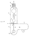
図1〜6は、本発明の例示的な実施形態を示す。図1〜6を参照すると、本発明の血液採取搬送装置10などの血液採取搬送装置は、流路48を有するランシングテープ12、および、ランシングテープ12に取り外し可能に接続された搬送カートリッジ14を含む。本発明の血液採取搬送装置10は、血液サンプルの曝露を減少させ、および、血液サンプルとサンプル安定剤の迅速な混合を提供するクローズドシステムを提供する。
1-6 illustrate an exemplary embodiment of the present invention. Referring to FIGS. 1 to 6, a blood collection and conveyance device such as the blood collection and
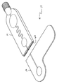
図10は、本開示の例示的な実施形態を示す。図10を参照すると、本発明の血液採取装置20などの生物学的流体採取システムはキット22を含み、該キットは、ランセット装置24、流路48を有するランシングテープ12および取り外し可能にランシングテープ12に接続された搬送カートリッジ14を有する血液採取搬送装置10、および、区画68を有する包装材26を有し、該包装材は、その中にランセット装置24および血液採取搬送装置10を受け入れるような大きさとされ、および、そうするように適合されている。
FIG. 10 illustrates an exemplary embodiment of the present disclosure. Referring to FIG. 10, a biological fluid collection system, such as the blood collection device 20 of the present invention, includes a
図15は、本開示の例示的な実施形態を示す。図15を参照すると、血液サンプルのための本開示の血液分離装置30は血液採取搬送装置10および遠心分離機32を含み、該血液採取搬送装置は、血液サンプルを受けるように適合されており、流路48を有するランシングテープ12および該ランシングテープに取り外し可能に接続された搬送カートリッジ14を有し、該遠心分離機は、搬送カートリッジ14を受け入れるように適合された受け入れポート74を有し、そのために、遠心分離機32内に搬送カートリッジ14が受け入れられ且つ搬送カートリッジ14に回転力が加えられた状態で、血液サンプルの血漿成分が細胞成分から分離される。
FIG. 15 illustrates an exemplary embodiment of the present disclosure. Referring to FIG. 15, a blood separation device 30 of the present disclosure for a blood sample includes a blood collection and
図1〜5を参照すると、ランシングテープ12は一般的に、長手方向部分40、長手方向部分40から延びている半径方向部分42、半径方向部分42上のターゲットまたはグラフィックインジケータ44、ターゲット44と流体連通する入口ポート46、ランシングテープ12内に一体的に形成された、入口ポート46と流体連通するランシングテープ流路48、および、ランシングテープ流路48および搬送カートリッジ14の部分と流体連通する出口ポート50を、下で説明するように含んでいる。図1を参照すると、ランシングテープ12はまた、上面45および下面47を含んでいる。下面47は、図11および12に示すように、ランシングテープ12を患者に取り外し可能に接着するための機構を含む。
1-5, the
一実施形態において、下面47は接着剤を含む。下面47は、ランシングテープ12を血液サンプルがアクセスされる患者の皮膚表面Sに固定できるように、接着剤を含む。一実施形態において、下面47の接着剤は、ランシングテープ12を患者の身体の皮膚表面S上に配置する前に取り除かれる粘着包帯と同様の剥離層によって保護されている。ランシングテープ12の下面47にいくらかの厚さを提供し、および、接着剤シールの安定性を向上させるのに役立つように、ヒドロゲルまたは他の層(図示せず)を含めることができる。また、一実施形態において、接着剤は、塗装工のテープ技術と同様にしてより液体漏れのない密封を作るための化学的性質を含むことができ、ここで、塗料自体からの濡れが接着剤と化学反応を起こし、塗料がテープの下に浸入することを防ぐための、より水漏れのないバリアを作り。重要なことには、接着剤は、患者の皮膚表面Sへのランシングテープ12の適切な接着を提供し、および、より良いサンプルを凝固検査のためにもたらす皮膚接触を最小化する。ランシングテープ12の接着剤は、下の創傷に端を発する血液がランシングテープ12内へ傷口を通って通過し、血液採取搬送装置10の内部で収集されるように、ランセット装置24によって穿刺され得る。一実施形態において、ランシングテープ12は、2つの層、皮膚と接触している接着剤層を有する底部、および、発せられている血液を受ける上部を含む。本発明の接着剤は、漏れ防止機構を含む。例えば、一実施形態において、自己密封または自己回復性ポリマーが使用される。他の実施形態において、ランシングテープ12の頂部はドーム形状のブリスターを含み、これは、ランセットの下で圧縮するが、ランシング動作の後でその元の形状に急いで戻り、それにより、血液が発展する空間を作成し、次いで、毛細管現象により血液採取搬送装置10の残りの部分へ吸って移動させる。他の実施形態において、ドーム形状のブリスターの元の形状への急戻は、創傷から血液を引き抜くのに役立つ真空力を可能にする。
In one embodiment, the
ランシングテープ12のターゲット44は、ランセット装置24のための位置合わせおよび照準機構を、図12に示すように提供する。一実施形態において、ターゲット44は円形の形状を有している。他の実施形態において、ターゲット44は、正方形または長方形の断面形状のような他の多角形断面形状を有することができる。図1および図2に示すように、ランシングテープ12のターゲット44は、入口ポート46およびランシングテープ流路48に対し流体連通しおよび位置合わせされている。
The
図1〜6を参照すると、搬送カートリッジ14は、大略して、ランシングテープ12の出口ポート50と流体連通する入口ポート52、入口ポート52と流体連通する入口リザーバ56、入口リザーバ56と流体連通する搬送カートリッジ流路58、搬送カートリッジ流路58と流体連通する出口リザーバすなわち分配バルブ60、出口リザーバ60と流体連通する出口ポート54、出口ポート54と連通して配置されたバルブ62、および、エンドキャップ64を含む。搬送カートリッジ14は、血液サンプルとサンプル安定剤との受動的かつ迅速な混合を提供するために、サンプル安定剤を含むように適合されている。サンプル安定剤は抗凝固剤であってもよく、または、例えば、RNA、タンパク質分析物、または他の要素などの血液中の特定の要素を保持するように設計された物質であってもよい。一実施形態において、サンプル安定剤は搬送カートリッジの流路58内に備えられる。他の実施形態において、サンプル安定剤は、入口ポート52または入口リザーバ56などの、搬送カートリッジ14の他の領域に備えられる。
With reference to FIGS. 1-6, the
一実施形態において、搬送カートリッジ流路58は、細胞成分36および血漿成分38を有する血液サンプル34(図14および16)の効率的な混合を促進するための蛇行形状を含む。以下に説明するように、遠心分離器32は、搬送カートリッジ14に加えられて、血漿成分38を細胞成分36から搬送カートリッジ流路58を介して分離するための回転力を提供する。他の実施形態において、搬送カートリッジ流路58は、血液サンプルの効率的な混合を促進するための他の形状を含む。
In one embodiment, the
バルブ62は、血漿成分を搬送カートリッジの出口リザーバ60内に密封するための閉じた位置と、血漿成分が出口ポート54およびエンドキャップ64を通って、図17に示すようなポイントオブケア検査装置90へ流れることを可能にするための開いた位置との間で遷移可能である。
The
図1〜5を参照すると、搬送カートリッジ14がランシングテープ12に、破断容易要素すなわち破断容易部分16を介して、取り外し可能に接続されている。搬送カートリッジ14がランシングテープ12に接続された状態で、搬送カートリッジ14の入口リザーバ56および入口ポート52は、ランシングテープ12のランシングテープ流路48および出口ポート50と流体連通している。破断容易要素16は、破断容易要素密封壁66を含む。図5を参照すると、ランシングテープ12から搬送カートリッジ14を取り外すために破断容易要素16が破断された後、破断容易要素密封壁66は、搬送カートリッジ14の入口ポート52を密封する。ランシングテープ12から搬送カートリッジ14を取り外すために破断容易要素16が破断された後、ランシングテープ12の出口ポート50もまた密封されて、ランシングテープ流路48を密封する。
With reference to FIGS. 1-5, a
図10を参照すると、本発明の血液採取装置20はキット22および包装材26を含み、キット22は、ランセット装置24、および、流路48を有するランシングテープ12およびランシングテープ12に取り外し可能に接続された搬送カートリッジ14を有する血液採取搬送装置10を有し、並びに、包装材26は、その中にランセット装置24および血液採取搬送装置10を受け入れるような大きさとされ、および、そうするように適合された大きさの区画68を有している。包装材26は、区画68を画定する本体または壁を含む。一実施形態において、包装材26の本体は、第1の区画70であって、その中に血液採取搬送装置10を受け入れる大きさとされ、且つ、そうするように適合された第1の区画70、および、第2の区画72であって、その中にランセット装置24を受け入れる大きさとされ、且つ、そうするように適合された第2の区画72を画定する。一実施形態において、包装材26はブリスターパッケージを備える。一実施形態において、シールカバーが包装材26の上方に、その中に血液採取搬送装置10およびランセット装置24を密封するように固定され、すなわち、シールカバーは、包装材26に対して実質的に不浸透性のエンクロージャを提供し、漏れ防止エンクロージャおよび保護エンクロージャを提供し、包装材26内に収容された血液採取搬送装置10およびランセット装置24の内容物を保護し、および/または、密封された滅菌環境をパッケージ内に維持する。包装材26のシールカバーは、温度、圧力、および湿度レベルの範囲で十分な密封を提供する。一実施形態において、不正開封の証拠もまた、包装材26の内容物に対する不正を示すための、シールカバーおよび/または包装材26の部分に固定された引き裂きストリップまたは他の指示手段の使用によって提供される。
Referring to FIG. 10, the blood collection device 20 of the present invention includes a
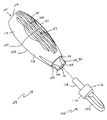
図7、8、9、12、および13を参照すると、本開示のランセット装置24が示されている。一実施形態において、ランセット装置24は、接触活性化ランセット装置であってもよい。他の実施形態において、ランセット装置24は、どんなタイプのランセット装置であってもよい。他の実施形態において、ランセット装置24は、ターゲット44またはランシングテープ12のドーム内に含まれるように寸法決めされてもよい。このように、ユーザーは、ランセットを活性化し、患者の皮膚を貫通するように、ターゲット44を押し下げることができる。
Referring to FIGS. 7, 8, 9, 12, and 13, a
一実施形態において、ランセット装置24は、大略して、ハウジング100、ハウジング100に移動可能に付随したシールド102、および、その中に配置されたランセット構造104を含む。後述するように、シールド102は、ハウジング100に対し同軸に移動可能に付随し、部分的にハウジング100内に配置され、ランセット構造104がシールド102内部に、シールド102に対し軸方向すなわち長手方向に移動可能に収容された状態で、部分的に外側へ、ハウジング100から延びている。ランセット構造104は穿刺要素106を含み、ランセット構造104は、少なくとも部分的にハウジング100内に配置され、および、穿刺要素106がハウジング100内に保持されている予備作動位置(図9)と穿刺要素106の少なくとも一部がハウジング100の前方端部110を通って延びている穿刺位置(図13)の間の移動に適合されている。
In one embodiment, the
ハウジング100は、細長い本体を画定し、望ましくは、末端または前方端部110を画定する本体112と、基端または後方端部116を画定する後部キャップ114で形成される。ハウジング100の内側部分は、概して開いており、内部キャビティ118を画定し、内部キャビティ118は後方端部116において後部キャップ114により閉じており、および、前方端部110を通る開口部120を備え、そこを通ってシールド102が延びている。本体112および後部キャップ114を一体的に形成してもよい。別のものとして、本体112および後部キャップ114は、互いに固定されてハウジング100を形成する別個の要素であってもよく、それは、ランセット装置24の組み立てにおいて助けになる。本体112および後部キャップ114は、適切な接着剤によって一緒に固定してもよく、または、それらの間に、摩擦嵌合またはスナップフィット構造などの機械的取り付けを提供する相互係合構造を含むことができる。代替実施形態において、本体112および後部キャップ114は一体的に形成された構造であってもよいので、一つのコンポネントとして一緒に成形することができる。
The
図7および図8に示すように、本体112および後部キャップ114によって画定されるハウジング100は反対側の側部121、122を有し、これらはそれぞれ、フィンガーグリップくぼみ123などの、くぼんだへこみまたは凹部として形成され得る、ユーザーの指に適合する曲面を含むことができる。2つの反対側のフィンガーグリップくぼみ123をハウジング100上に備え得る一方、ハウジング100内に形成された唯1つのフィンガーグリップくぼみ123を本発明に従って備え得ることを理解できよう。さらに、後部キャップ114の先端面など、ハウジング100の後方端部116はまた、後部フィンガーグリップくぼみ124などの、くぼんだへこみまたは凹部として形成され得る、ユーザーの指に適合する曲面も含むことができる。側部のフィンガーグリップくぼみ123および後部のフィンガーグリップのくぼみ124は、ランセット装置24を操作する際、および、血液の送出、抜き取り、または収集処置においてランセット装置24を使用する際にユーザーを支援するようにユーザーの指先に実質的に合致した人間工学的形状の曲面を提供し、および、複数の指グリップ位置をユーザーのために提供することができる。一実施形態において、ハウジング100は、ハウジング100とユーザーの指先の間のグリップを概して向上させるための、ハウジング100に沿って延在し且つハウジング100と一体に形成された複数の長手方向リブ125およびトラフ126などの構造をさらに含むことができ、それは、ユーザーに彼または彼女の指先を配置する場所を指示するための視覚および触覚の手がかりをユーザーに提供することができる。
As shown in FIGS. 7 and 8, the
シールド102は、開口部120から外側へ、ハウジング100の前方端部110を通って延びる。図9および図13に示すように、シールド102は、前方端部132と後方端部134の間に延びたシールド体130であって、それを通って延在する内部キャビティ136を画定するシールド体130を有する、概して円筒形の中空構造である。シールド体130の前方端部132は、そこを通る前方開口部140を含む前方端部壁138を画定し、ユーザーによってランセット装置24が作動されたときに、そこを通ってランセット構造104の穿刺要素106が延在する。前方端部壁138は、一般に、穿刺要素によって穿刺されるべき、ユーザーの身体上の意図した領域と接触するための開口部140の周りの小さな接触領域を画定する。シールド102は、ハウジング100内で軸方向にまたは長手方向に移動可能である。シールド102およびハウジング100は、ハウジング100を通してシールド102を案内する、対応するガイド面を含んでいてもよい。
The shield 102 extends outward from the
ランセット装置24は、ハウジング100内に配置された、シールド102を通って延びるランセット構造104をさらに含む。図9および図13に示すように、ランセット構造104は、ランセット108の形態で示された穿刺要素106であって、その前方端部において穿刺端部109を画定する穿刺要素106を含む。ランセット構造104は、シールド体130の内部キャビティ136を通る軸方向または長手方向の移動であって、穿刺端部109をシールド体130内に維持した状態での初期の装備位置すなわち予備作動位置と穿刺端部109がシールド体130の前方開口部140を超えて延びる穿刺位置の間の移動に適合されている。穿刺端部109は、患者の皮膚を穿刺するように適合され、および、先のとがった端部、ブレードの端部などを画定することができる。穿刺端部109は、特定の方向に配向した、ブレードの先のとがった端部など、好ましい配向方向を含むことができる。
図9および図13に示すように、保持ハブ150が、シールド体130の後方端部134に備えられている。保持ハブ150は、シールド体130の後方端部134内に配置または保持された別個の保持構造として提供される。一実施形態において、シールド体130は、保持ハブ150を支持しおよび位置決めしてアセンブリ内で補助するための面を含むことができる。他の実施形態において、保持ハブ150は、シールド体130の上に直接、成形または形成され得る。
As shown in FIGS. 9 and 13, the holding hub 150 is provided at the
保持ハブ150は、ハウジング100内に引き込まれた、初期装備位置におけるランセット構造104を保持するためのレバー構造152を、図9に示すように画定する。保持ハブ150およびランセット構造104は、保持ハブ150がランセット構造104をハウジング100内で初期装備位置に保持するように、相互に締まり嵌め係合している。
The retention hub 150 defines a lever structure 152 that is retracted into the
また、レバー要素152は、ハウジング100内に画定された構造との係合に接触するように適合される。例えば、ハウジング100の後部キャップ114は、その中に延在する構造であって、一体に形成された、少なくとも1つの内側側壁上に、望ましくはその対向する2つの内側側壁上に延在する内部コンタクト128などを、図9および図13に示すように含むことができる。各内部コンタクト128は、レバー要素152の接触面との係合に接触するための係合面129であって、カム面を形成する係合面129を含む。このようにして、内部コンタクト128のペアはレバー要素152と係合することができ、それによって、レバー要素152の旋回運動中に連続的なカム様接触面を提供する。
The lever element 152 is also adapted to contact engagement with a structure defined within the
ランセット構造104のランセット装置24を通る移動は、駆動ばね160により提供される付勢力によって達成される。駆動ばね160は、穿刺位置に向けて装置を貫いてランセット構造104を駆動するためにランセット構造104に対し付勢力を及ぼすように適合しており、および、ハウジング100の後方端部とランセット構造104の間に配置され得る。ランセット構造104が装備位置にあるとき、駆動ばね160は、ハウジング100の後方端部とランセット構造104の間などでランセット構造に対して力を及ぼし、ランセット構造104を穿刺位置に向けて付勢する。
Movement of the
図9および図13を参照すると、引き込みばね162を、ランセット装置24の前方端部に、ランセット構造104が軸方向に穿刺位置へ移動された後でランセット構造104をシールド体130内に引き込むために備えることができる。引き込みばね162は、ランセット構造104の前方面とシールド体130の前方端部壁138内の内面との間に延在する。引き込みばね162は、典型的には圧縮バネであり、圧縮された状態にあるときにエネルギーを貯蔵することができる。
Referring to FIGS. 9 and 13, a
図7および図8を参照すると、ランセット装置24は、ランセット装置24をその使用前に保護的に覆う保護カバー170をさらに含んでもよい。保護カバー170は、ランセット装置24の前方端部に付随したタブ部材172を含むことができ、それは、シールド体130の前方端部壁138の無菌性を維持する。タブ部材172は、前方タブ部材174および従属するスカート176を含むことができる。従属するスカート176は、シールド体130の前方端部132と協働するように適合され、前方端部132を概ね、包含または包囲する。従属するスカート176はまた、ハウジング100の本体112の前方端部110と接触する。このように、タブ部材172は、本体112の前方開口部120およびシールド体130の前方開口部140を囲む。また、このような構成は、本体112およびシールド体130のそれぞれの前方端部を互いに対して固定された関係に維持し、これにより、ランセット装置24の早すぎる活性化を引き起こす可能性がある、それらの間の移動を防止する。一実施形態において、保護カバー170の後の部分178は、穿刺要素106の少なくとも一部を包含するように、シールド体130内に延びていてもよい。
7 and 8, the
本発明のランセット装置の各構成要素は全て、典型的には、医療用グレードのプラスチック材料などの、成形プラスチック材料で形成されている。ランセット108は、皮膚を穿刺するために適合された任意の適切な材料から構成することができ、および、典型的には、ステンレス鋼のような外科的グレードの金属である。 All components of the lancet device of the present invention are typically formed of a molded plastic material, such as a medical grade plastic material. Lancet 108 can be constructed of any suitable material adapted to puncture the skin and is typically a surgical grade metal such as stainless steel.
図7〜9および図13を参照し、ランセット装置24の使用について、ここで説明する。ランセットアセンブリを使用のために準備するために、ユーザーは、指と親指の間などに反対側の側部121、122上を把持し、および、保護カバー170を図8に示すように前方端部から取り外し、それにより、ハウジング100の本体112の前方端部から延びているシールド体130を露出させる。シールド体130の前方端部壁138は、次に、図11〜13に示したような患者の皮膚表面Sなどの、血液の流れを開始することが望まれているユーザーの身体または他の人の身体上の位置と接触され得る。
The use of
本体に対し一旦、配置されると、ユーザーは、シールド体130を肌面Sに対し強制する下向きの力を、ハウジング100上に及ぼす。保持ハブ150はシールド体130の後方端部134に隣接していることから、後部キャップ114に向かうシールド体130のこのような変位が、後部キャップ114に向かう、保持ハブ150の対応する動きを生じさせる。このような動きは、駆動ばね160を圧縮させる。駆動ばね160のこの圧縮は、駆動ばね160に、ランセット構造104を軸方向に前方へシールド体130を通って穿刺位置へ推進するのに十分な付勢力を供給し、それによって、ランセット構造104を装備位置に備える。しかしながら、この時点で、ランセット構造104は依然として、穿刺端部109が保持ハブ150とランセット構造104の間の締まり嵌め係合によってシールド体130内に引き込まれるように維持されている。
Once placed on the body, the user exerts a downward force on the
保持ハブ150のそのような後方への動きは、レバー要素152の対応する接触面と係合しおよび共同で動作するように、内部コンタクト128の係合面129のカム面を後部キャップ114内で生じさせる。従って、対応するカム接触面は、ランセット装置24のためのアクチュエータ要素を提供する。このような係合および共同動作は、シールド体130を通じてランセット構造104を解放するように、レバー要素152を旋回させる。最終的に、そのような旋回は、図13に示すように、保持ハブ150とランセット構造104の間の締まり嵌め係合が解除される点まで、レバー要素152を旋回させる。駆動ばね160の付勢力は、ランセット構造104を下方へ推進して、後部キャップ114から軸方向にハウジング100およびシールド体130を通って遠ざける。
Such rearward movement of the retention hub 150 causes the cam surface of the
図15を参照すると、細胞成分36および血漿成分38を有する血液サンプル34のための、本発明の血液分離装置30(図14および16)は、血液サンプルを受けるように適合され、および、流路48を有するランシングテープ12およびランシングテープ12に取り外し可能に接続された搬送カートリッジ14を有する血液採取搬送装置10、並びに、搬送カートリッジ14を受けるように適合された受け入れポート74を有する遠心分離機32を含み、そのために、遠心分離機32内に搬送カートリッジ14が受け入れられ且つ搬送カートリッジ14に回転力が加えられた状態で、血液サンプルの血漿成分が細胞成分から分離される。遠心分離機32は、搬送カートリッジ14、基部すなわち底部78、ヒンジ式部分80によって移動可能に基部78に接続された上蓋部76、および、基部78内に収容される回転力要素82を受けるように適合された複数の受け入れポート74を含む。上蓋部76は、搬送カートリッジ14を図15に示すように受け入れポート74内に配置することができる開放位置と閉鎖位置の間で遷移可能である。カートリッジ14が遠心分離機32内に受け入れられた状態で、回転力が搬送カートリッジ14に印加され、以下でより詳細に説明するように、血漿成分38を細胞成分36から分離する。
Referring to FIG. 15, a blood separation device 30 (FIGS. 14 and 16) of the present invention for a blood sample 34 having a cellular component 36 and a plasma component 38 is adapted to receive a blood sample and a flow path. A blood collection and
図10〜17を参照し、本発明の血液採取搬送装置の使用について、ここで説明する。図10〜12を参照すると、部位を選択し次第、臨床医はランシングテープ12を、それに接続された搬送カートリッジ14と一緒に、包装材26から取り外す。臨床医は、次いで、図11および12に示されるように、選択した採取部位の上にランシングテープ12を接着する。ランセット装置24のためのターゲットは、ランシングテープ12上に備えられたターゲット44で強調表示される。臨床医は、次いで、ランセット装置24の先端をターゲット44の上に配置し、および、ランセット装置24を活性化して皮膚Sを穿刺するために、その部位に対して矢印Aの方向に押圧する。ターゲット44は、ランシングテープ12のランシングテープ流路48を介して搬送カートリッジ14の入口リザーバ56へ毛細管現象によって血液を運ぶための、流路48を通る統合された流れに対応する。
搬送カートリッジ14は、曲がりくねった(または他の)流路58内に、サンプルの効率的な混合を促進するための抗凝固剤を含んでいる。搬送カートリッジ14の入口リザーバ56が充填されると、臨床医は、ランシングテープ12と搬送カートリッジ14の間の破断容易要素16をポキッと折ることができる。破断されたときは、搬送カートリッジ14の流路58は外部環境から密封される。
With reference to FIGS. 10-17, the use of the blood sampling and conveying apparatus of the present invention will now be described. With reference to FIGS. 10-12, upon selection of a site, the clinician removes the lancing
The
図15を参照すると、処理の次のステップは、特に搬送カートリッジ14のために設計されたポイントオブケア遠心分離機32への手動挿入を伴う。搬送カートリッジ14の分配バルブ60内に血漿成分38が収集されるように、血液は素早くスピンされ、および、小容量のため数秒以内に分離される。搬送カートリッジ14は、手動で遠心分離機32から取り外される。その後、図17を参照すると、搬送カートリッジ14の分配バルブ60内の血液サンプルの血漿成分は、分配バルブ60をウェルまたはポイントオブケア検査装置90の受け入れポート92へ押し込むことによって、所望の試験を実施するために、搬送カートリッジ14の出口ポート54を介して分配される。分配バルブ60は、バルブ60が上述したように押下されるまで漏れを回避するためのバルブ62を有している。搬送カートリッジ14は、次いで廃棄することができ、或いは、追加の検査処置のために保持することができる。また、遠心分離機32が読み取ることができるバーコードラベルまたはRFIDタグを、様々な情報をシステムに提供するために、搬送カートリッジ14上に備えてもよい。
Referring to FIG. 15, the next step in the process involves manual insertion into a point-of-
従来のシステムに対する本発明のいくつかの利点は、それがサンプルの曝露を減少するクローズドシステムであること、それがサンプルの受動的かつ迅速な抗凝固剤との混合を提供すること、それがサンプルを搬送することなくサンプルの分離を容易にすること、および、それが純粋な血漿をポイントオブケア検査装置90に搬送できることである。
Some advantages of the present invention over conventional systems are that it is a closed system that reduces sample exposure, that provides passive and rapid mixing of the sample with the anticoagulant, which The separation of the sample without transporting the sample, and the ability to transport pure plasma to the point-of-
本発明の血液採取搬送装置はまた、全血サンプルを入力として用いるポイントオブケア検査装置に血液サンプルを搬送するために使用することができる。本発明の血液採取搬送装置のすべてのアプリケーションが、血漿を遠心分離によって作成することを必要とするわけではない。 The blood collection and transport device of the present invention can also be used to transport a blood sample to a point-of-care test device that uses a whole blood sample as input. Not all applications of the blood collection and delivery device of the present invention require that the plasma be generated by centrifugation.
本開示は、例示的な設計を有するものとして説明してきたが、本発明はさらに、本開示の精神および範囲内で変更することができる。本出願はしたがって、その一般原則を使用して、本開示の任意のバリエーション、用途、または適応をカバーすることを意図している。さらに、本出願は、当技術分野で公知または慣行内に入るような本開示からの逸脱であって本開示が関係しおよび添付の特許請求の範囲の範囲内に入る逸脱をカバーすることを意図している。 While this disclosure has been described as having an exemplary design, the present invention can be further modified within the spirit and scope of this disclosure. This application is therefore intended to cover any variations, uses, or adaptations of the disclosure using its general principles. Further, this application is intended to cover deviations from the present disclosure as known or within the skill of the art to which this disclosure pertains and which fall within the scope of the appended claims. doing.
Claims (17)
流路、および、該流路と流体連通する出口ポートを有するランシングテープ、および、
該ランシングテープに取り外し可能に接続された搬送カートリッジであって、入口ポート、および、該入口ポートと流体連通するリザーバを有する搬送カートリッジ
を備え、
前記搬送カートリッジが密封壁を含む破断容易要素であってプラスチック材料で形成されている破断容易要素を介して前記ランシングテープに接続された状態で、前記入口ポートが前記出口ポートと流体連通し、および、
前記破断容易要素を前記密封壁から屈曲破断することによって前記搬送カートリッジが前記ランシングテープから切り離された状態で、前記入口ポートが前記密封壁によって密封されて前記リザーバを密封する、
血液採取搬送装置。 A blood collection and conveyance device,
A lancing tape having a flow path and an outlet port in fluid communication with the flow path; and
A transport cartridge removably connected to the lansing tape, comprising a transport cartridge having an inlet port and a reservoir in fluid communication with the inlet port;
The inlet port is in fluid communication with the outlet port, with the transport cartridge connected to the lance tape via a breakable element comprising a sealing wall and formed of a plastic material ; and ,
The inlet port is sealed by the sealing wall to seal the reservoir in a state where the transport cartridge is separated from the lansing tape by bending and breaking the easy-breaking element from the sealing wall;
Blood collection and transportation device.
前記ランシングテープはランセット装置のためのターゲットを含む、血液採取搬送装置。 The blood sampling and conveying apparatus according to claim 1,
The lancet tape includes a target for a lancet device, a blood collection and transfer device.
前記ランシングテープの前記ターゲットは前記流路と整列される、血液採取搬送装置。 In the blood sampling and conveying apparatus according to claim 2,
The blood sampling and conveying apparatus, wherein the target of the lancing tape is aligned with the flow path.
前記ランシングテープの前記ターゲットは円形のグラフィックインジケータである、血液採取搬送装置。 In the blood sampling and conveying apparatus according to claim 2,
The blood sampling and conveying apparatus, wherein the target of the lancing tape is a circular graphic indicator.
前記搬送カートリッジは前記リザーバと流体連通する搬送カートリッジ流路を含む、血液採取搬送装置。 The blood sampling and conveying apparatus according to claim 1,
The blood collection and transfer apparatus, wherein the transfer cartridge includes a transfer cartridge channel in fluid communication with the reservoir.
前記搬送カートリッジ流路はサンプル安定剤を備える、血液採取搬送装置。 In the blood sampling and conveying apparatus according to claim 5,
The blood collection and transfer apparatus, wherein the transfer cartridge channel includes a sample stabilizer.
前記搬送カートリッジは前記搬送カートリッジ流路と流体連通する分配バルブを含み、
前記搬送カートリッジ流路は前記分配バルブと前記リザーバの間に配置される、血液採取搬送装置。 In the blood sampling and conveying apparatus according to claim 5,
The transport cartridge includes a distribution valve in fluid communication with the transport cartridge flow path;
The blood collection and transfer device, wherein the transfer cartridge channel is disposed between the distribution valve and the reservoir.
穿刺要素を有するランセット装置、および、
血液採取搬送装置を備え、該血液採取搬送装置が、
流路、該流路と流体連通する出口ポート、および、該流路と整列したターゲットを有するランシングテープであって、該ターゲットは前記ランセット装置の前記穿刺要素のためである、ランシングテープ、および、
該ランシングテープに取り外し可能に接続された搬送カートリッジであって、入口ポート、および、該入口ポートと流体連通するリザーバを有する搬送カートリッジを備え、 前記搬送カートリッジが密封壁を含む破断容易要素であってプラスチック材料で形成されている破断容易要素を介して前記ランシングテープに接続された状態で、前記入口ポートが前記出口ポートと流体連通し、および、
前記破断容易要素を前記密封壁から屈曲破断することによって前記搬送カートリッジが前記ランシングテープから切り離された状態で、前記入口ポートが前記密封壁によって密封されて前記リザーバを密封する、
血液採取装置。 A blood collection device,
A lancet device having a piercing element, and
A blood collecting and conveying device, the blood collecting and conveying device comprising:
Lansing tape having a flow path, an outlet port in fluid communication with the flow path, and a target aligned with the flow path, wherein the target is for the piercing element of the lancet device; and
A connected to the transported cartridge removably to said lancing tape, inlet port, and a transport cartridge having a reservoir in fluid communication with said inlet port, the transfer cartridge is a readily breakable element comprising a sealing wall The inlet port is in fluid communication with the outlet port, connected to the lancing tape via an easily breakable element formed of a plastic material ; and
The inlet port is sealed by the sealing wall to seal the reservoir in a state where the transport cartridge is separated from the lansing tape by bending and breaking the easy-breaking element from the sealing wall;
Blood collection device.
前記ランシングテープの前記ターゲットは円形のグラフィックインジケータである、血液採取装置。 The blood collection device according to claim 8,
The blood collection device, wherein the target of the lancing tape is a circular graphic indicator.
前記搬送カートリッジは前記リザーバと流体連通する搬送カートリッジ流路を含む、血液採取装置。 The blood collection device according to claim 9,
The blood collection apparatus, wherein the transport cartridge includes a transport cartridge channel in fluid communication with the reservoir.
前記搬送カートリッジ流路はサンプル安定剤を備える、血液採取装置。 The blood collection device according to claim 10,
The blood collection apparatus, wherein the transport cartridge channel includes a sample stabilizer.
前記搬送カートリッジは前記搬送カートリッジ流路と流体連通する分配バルブを含み、
前記搬送カートリッジ流路は前記分配バルブと前記リザーバの間に配置される、血液採取装置。 The blood collection device according to claim 10,
The transport cartridge includes a distribution valve in fluid communication with the transport cartridge flow path;
The blood collection apparatus, wherein the transport cartridge flow path is disposed between the distribution valve and the reservoir.
穿刺要素を有するランセット装置、
血液採取搬送装置であって、
流路、該流路と流体連通する出口ポート、および、該流路と整列したターゲットを有するランシングテープであって、該ターゲットは前記ランセット装置の前記穿刺要素のためである、ランシングテープ、および、
該ランシングテープに取り外し可能に接続された搬送カートリッジであって、入口ポート、および、該入口ポートと流体連通するリザーバを有する搬送カートリッジを備え、
前記搬送カートリッジが密封壁を含む破断容易要素であってプラスチック材料で形成されている破断容易要素を介して前記ランシングテープに接続された状態で、前記入口ポートが前記出口ポートと流体連通し、および、
前記破断容易要素を前記密封壁から屈曲破断することによって前記搬送カートリッジが前記ランシングテープから切り離された状態で、前記入口ポートが前記密封壁によって密封されて前記リザーバを密封する、血液採取搬送装置、および、
前記ランセット装置および前記血液採取搬送装置と同一の大きさとされた区画をその中に有する包装材であって、該区画が、その中に前記ランセット装置および前記血液採取搬送装置を受け入れるように適合されている、包装材
を備えた血液採取装置。 A blood collection device,
A lancet device having a piercing element,
A blood collection and conveyance device,
Lansing tape having a flow path, an outlet port in fluid communication with the flow path, and a target aligned with the flow path, wherein the target is for the piercing element of the lancet device; and
A transport cartridge removably connected to the lansing tape, comprising a transport cartridge having an inlet port and a reservoir in fluid communication with the inlet port;
The inlet port is in fluid communication with the outlet port, with the transport cartridge connected to the lance tape via a breakable element comprising a sealing wall and formed of a plastic material ; and ,
A blood sampling and conveying device, wherein the inlet port is sealed by the sealing wall to seal the reservoir in a state where the conveying cartridge is separated from the lanching tape by bending and breaking the easy-breaking element from the sealing wall; and,
A packaging material therein having a compartment sized the same as the lancet device and the blood collection and transport device, wherein the compartment is adapted to receive the lancet device and the blood collection and transport device therein. A blood collection device with a packaging material.
前記包装材はブリスターパッケージを備える、血液採取装置。 The blood collection device according to claim 13,
The blood collection apparatus, wherein the packaging material comprises a blister package.
前記ランシングテープは接着剤を該ランシングテープの下面上に含む、血液採取装置。 The blood collection device according to claim 13,
The blood sampling device, wherein the lansing tape includes an adhesive on a lower surface of the lansing tape.
前記血液サンプルを受け入れるように適合された血液採取搬送装置であって、
流路、および、該流路と流体連通する出口ポートを有するランシングテープ、および、
該ランシングテープに取り外し可能に接続された搬送カートリッジであって、入口ポート、および、該入口ポートと流体連通するリザーバを有する搬送カートリッジを備え、
前記搬送カートリッジが密封壁を含む破断容易要素であってプラスチック材料で形成されている破断容易要素を介して前記ランシングテープに接続された状態で、前記入口ポートが前記出口ポートと流体連通し、および、
前記破断容易要素を前記密封壁から屈曲破断することによって前記搬送カートリッジが前記ランシングテープから切り離された状態で、前記入口ポートが前記密封壁によって密封されて前記リザーバを密封する、血液採取搬送装置、並びに、
前記搬送カートリッジを受け入れるように適合された受け入れポートを有する遠心分離機であって、該遠心分離機内に前記搬送カートリッジが受け入れられ且つ前記搬送カートリッジに回転力が加えられた状態で、前記血液サンプルの前記血漿成分が前記リザーバを介して前記細胞成分から分離される、遠心分離機
を備えた血液分離装置。 A blood separation device for a blood sample having a cellular component and a plasma component comprising:
A blood collection and transport device adapted to receive the blood sample,
A lancing tape having a flow path and an outlet port in fluid communication with the flow path; and
A transport cartridge removably connected to the lansing tape, comprising a transport cartridge having an inlet port and a reservoir in fluid communication with the inlet port;
The inlet port is in fluid communication with the outlet port, with the transport cartridge connected to the lance tape via a breakable element comprising a sealing wall and formed of a plastic material ; and ,
A blood sampling and conveying device, wherein the inlet port is sealed by the sealing wall to seal the reservoir in a state where the conveying cartridge is separated from the lanching tape by bending and breaking the easy-breaking element from the sealing wall; And
A centrifuge having a receiving port adapted to receive the transport cartridge, wherein the transport sample is received in the centrifuge and a rotational force is applied to the transport cartridge. A blood separation apparatus comprising a centrifuge, wherein the plasma component is separated from the cell component via the reservoir.
前記ランシングテープは接着剤を該ランシングテープの下面上に含む、血液分離装置。 The blood separation device according to claim 16,
The blood separating device, wherein the lansing tape includes an adhesive on a lower surface of the lansing tape.
Applications Claiming Priority (3)
| Application Number | Priority Date | Filing Date | Title |
|---|---|---|---|
| US201361811918P | 2013-04-15 | 2013-04-15 | |
| US61/811,918 | 2013-04-15 | ||
| PCT/US2014/033939 WO2014172247A1 (en) | 2013-04-15 | 2014-04-14 | Blood sampling transfer device |
Publications (2)
| Publication Number | Publication Date |
|---|---|
| JP2016518926A JP2016518926A (en) | 2016-06-30 |
| JP6247380B2 true JP6247380B2 (en) | 2017-12-13 |
Family
ID=51704179
Family Applications (1)
| Application Number | Title | Priority Date | Filing Date |
|---|---|---|---|
| JP2016509007A Active JP6247380B2 (en) | 2013-04-15 | 2014-04-14 | Blood collection and transportation device |
Country Status (9)
| Country | Link |
|---|---|
| US (1) | US10925530B2 (en) |
| EP (1) | EP2986223B1 (en) |
| JP (1) | JP6247380B2 (en) |
| CN (2) | CN203898315U (en) |
| BR (1) | BR112015026159B1 (en) |
| CA (1) | CA2909183C (en) |
| ES (1) | ES2663791T3 (en) |
| MX (1) | MX370653B (en) |
| WO (1) | WO2014172247A1 (en) |
Families Citing this family (17)
| Publication number | Priority date | Publication date | Assignee | Title |
|---|---|---|---|---|
| EP2917362A4 (en) * | 2012-11-07 | 2016-07-13 | Sandstone Diagnostics Inc | Methods and devices for processing samples and counting cells |
| ES2686359T3 (en) * | 2013-04-15 | 2018-10-17 | Becton, Dickinson And Company | Biological fluid collection device |
| MX370653B (en) * | 2013-04-15 | 2019-12-18 | Becton Dickinson Co | Blood sampling transfer device. |
| CA2985716C (en) * | 2015-08-06 | 2021-04-06 | Becton, Dickinson And Company | Biological fluid collection device and biological fluid collection system |
| EP4035762B1 (en) | 2015-09-09 | 2023-11-01 | Drawbridge Health, Inc. | Devices for sample collection, stabilization and preservation |
| EP3184158B1 (en) * | 2015-12-21 | 2019-01-16 | Roche Diagniostics GmbH | Blood collector with capillary structure |
| EP3538452B1 (en) * | 2016-11-11 | 2022-05-11 | Atomo Diagnostics Limited | Integrated fluid module and test device |
| BR112019014231A2 (en) | 2017-01-10 | 2020-03-17 | Drawbridge Health, Inc. | DEVICES, SYSTEMS AND METHODS FOR SAMPLE COLLECTION |
| US11696711B2 (en) * | 2017-07-06 | 2023-07-11 | Becton, Dickinson And Company | Biological fluid collection device |
| EP3875028B1 (en) * | 2017-07-13 | 2023-03-29 | Becton, Dickinson and Company | Biological fluid collection device |
| US11604204B2 (en) | 2019-06-03 | 2023-03-14 | University Of Washington | Self-contained systems and methods for controlled dispensing of hazardous fluid |
| EP3944814B1 (en) * | 2020-07-30 | 2022-12-07 | Protzek Biotec GmbH | Device for taking a liquid sample |
| CN113092795A (en) * | 2021-02-24 | 2021-07-09 | 南京鼓楼医院 | Cell transfer device for blood cell detection |
| US11877848B2 (en) * | 2021-11-08 | 2024-01-23 | Satio, Inc. | Dermal patch for collecting a physiological sample |
| US11964121B2 (en) | 2021-10-13 | 2024-04-23 | Satio, Inc. | Mono dose dermal patch for pharmaceutical delivery |
| US11510602B1 (en) * | 2021-11-08 | 2022-11-29 | Satio, Inc. | Dermal patch for collecting a physiological sample |
| FR3133922A1 (en) * | 2022-03-25 | 2023-09-29 | Belmont Diagnostics | Microfluidic device for obtaining a plasma-reactive mixture and method of implementation |
Family Cites Families (77)
| Publication number | Priority date | Publication date | Assignee | Title |
|---|---|---|---|---|
| US3322114A (en) | 1964-07-01 | 1967-05-30 | Hynson Westcott & Dunning Inc | Apparatus for securing a sample of blood plasma for testing |
| US3640388A (en) | 1970-08-20 | 1972-02-08 | Damon Corp | Dialyzing liquid-collecting container |
| US4511349A (en) * | 1982-07-06 | 1985-04-16 | Beckman Instruments, Inc. | Ultracentrifuge tube with multiple chambers |
| US4627445A (en) | 1985-04-08 | 1986-12-09 | Garid, Inc. | Glucose medical monitoring system |
| US5046509A (en) | 1988-12-30 | 1991-09-10 | Spacelabs, Inc. | Device for the conditioning, handling and measurement of blood |
| JPH0778025B2 (en) | 1990-03-20 | 1995-08-23 | 日本赤十字社 | Method for producing immunoglobulin G |
| US5055203A (en) | 1990-05-22 | 1991-10-08 | Eastman Kodak Company | Blood collection device with reduced serum dispensing volume and integral needle |
| US5163442A (en) * | 1991-07-30 | 1992-11-17 | Harry Ono | Finger tip blood collector |
| US5231993A (en) | 1991-11-20 | 1993-08-03 | Habley Medical Technology Corporation | Blood sampler and component tester with guide member |
| US5726026A (en) | 1992-05-01 | 1998-03-10 | Trustees Of The University Of Pennsylvania | Mesoscale sample preparation device and systems for determination and processing of analytes |
| US5422018A (en) * | 1994-01-31 | 1995-06-06 | Applied Imaging | Centrifuge tube and adaptor |
| US5636640A (en) | 1995-02-06 | 1997-06-10 | Volunteers For Medical Engineering | Liquid sampling and test apparatus |
| US6074183A (en) | 1995-02-09 | 2000-06-13 | First Medical, Inc. | Peristaltic system and method for plasma separation and blood dispensation |
| US5839715A (en) | 1995-05-16 | 1998-11-24 | Alaris Medical Systems, Inc. | Medical adapter having needleless valve and sharpened cannula |
| CA2178523C (en) | 1995-06-09 | 2001-08-28 | Tomohiro Kitagawa | Plasma separation filter, plasma separation method using the same and plasma separation apparatus |
| US5856174A (en) | 1995-06-29 | 1999-01-05 | Affymetrix, Inc. | Integrated nucleic acid diagnostic device |
| WO1998040735A1 (en) * | 1997-03-12 | 1998-09-17 | Kyoto Daiichi Kagaku Co., Ltd. | Testing instrument for analyzing liquid sample |
| US6506167B1 (en) | 1997-12-24 | 2003-01-14 | I-Design Co., Ltd. | Blood-collecting tubes |
| US6948843B2 (en) | 1998-10-28 | 2005-09-27 | Covaris, Inc. | Method and apparatus for acoustically controlling liquid solutions in microfluidic devices |
| US6264619B1 (en) * | 1999-09-01 | 2001-07-24 | Becton, Dickinson And Company | Kit for drawing a blood sample |
| US6319719B1 (en) | 1999-10-28 | 2001-11-20 | Roche Diagnostics Corporation | Capillary hematocrit separation structure and method |
| IL139845A0 (en) | 1999-11-26 | 2002-02-10 | Cellcontrol Biomedical Lab Gmb | Method of and container for storing and transporting vital tissue, fluid or cell materials |
| US6869405B2 (en) * | 2001-03-30 | 2005-03-22 | Becton, Dickinson And Company | Blunt cannula and filter assembly and method of use with point-of-care testing cartridge |
| CN1273075C (en) * | 2001-07-13 | 2006-09-06 | 爱科来株式会社 | Analyzing apparatus, piercing element integrally installed body for temperature measuring device with analyzing apparatus, and body fluid sampling apparatus |
| ATE479490T1 (en) | 2001-10-11 | 2010-09-15 | Aviva Biosciences Corp | METHOD FOR SEPARATING RARE CELLS FROM FLUID SAMPLES |
| US7166443B2 (en) | 2001-10-11 | 2007-01-23 | Aviva Biosciences Corporation | Methods, compositions, and automated systems for separating rare cells from fluid samples |
| DE10208575C1 (en) | 2002-02-21 | 2003-08-14 | Hartmann Paul Ag | Blood analyzer device comprises needles, test media, analyzer and display, and has carrier turned with respect to main body, to position needle and test media |
| EP1477804A4 (en) | 2002-02-27 | 2016-12-28 | Pfaff Medical Gmbh | Instrument for separating plasma or serum, method of collecting plasma or serum, method of separating plasma or serum, test carrier and glass fiber |
| US8702624B2 (en) | 2006-09-29 | 2014-04-22 | Sanofi-Aventis Deutschland Gmbh | Analyte measurement device with a single shot actuator |
| EP1531883B1 (en) | 2002-08-23 | 2011-10-12 | CaridianBCT, Inc. | A set of bags for the separation by centrifugation of a composite fluid |
| AU2003284558A1 (en) | 2002-11-19 | 2004-06-15 | Sekisui Chemical Co Ltd | Plasma or serum separation membrane and filter apparatus including the plasma or serum separation membrane |
| US20040143226A1 (en) | 2003-01-16 | 2004-07-22 | Becton, Dickinson And Company | Blood collection set with venting mechanism |
| JP2007503597A (en) | 2003-06-13 | 2007-02-22 | ザ ジェネラル ホスピタル コーポレーション | Microfluidic system for removing red blood cells and platelets from blood based on size |
| WO2005018710A2 (en) | 2003-08-20 | 2005-03-03 | Facet Technologies, Llc | Blood sampling device |
| US7476326B2 (en) | 2003-09-26 | 2009-01-13 | Ahn Chong H | On-chip sample preparation for whole blood analysis |
| US7763209B2 (en) | 2004-03-11 | 2010-07-27 | Handylab, Inc. | Sample preparation device and method |
| US20050273019A1 (en) | 2004-06-02 | 2005-12-08 | Becton, Dickinson And Company | Blood collection set with venting mechanism |
| JP2004361419A (en) | 2004-08-26 | 2004-12-24 | Fuji Photo Film Co Ltd | Blood filtering unit |
| WO2006047831A1 (en) | 2004-11-03 | 2006-05-11 | Agen Biomedical Limited | Detection device and method |
| US20090136982A1 (en) | 2005-01-18 | 2009-05-28 | Biocept, Inc. | Cell separation using microchannel having patterned posts |
| US8158410B2 (en) | 2005-01-18 | 2012-04-17 | Biocept, Inc. | Recovery of rare cells using a microchannel apparatus with patterned posts |
| US8206650B2 (en) * | 2005-04-12 | 2012-06-26 | Chromedx Inc. | Joint-diagnostic spectroscopic and biosensor meter |
| US7473216B2 (en) | 2005-04-21 | 2009-01-06 | Fresenius Hemocare Deutschland Gmbh | Apparatus for separation of a fluid with a separation channel having a mixer component |
| WO2007002579A2 (en) | 2005-06-23 | 2007-01-04 | Bioveris Corporation | Assay cartridges and methods for point of care instruments |
| JP2007050100A (en) * | 2005-08-18 | 2007-03-01 | Rohm Co Ltd | Chip for sampling specimen |
| CN1935285B (en) * | 2005-09-19 | 2012-07-18 | 许明正 | Venous catheter setter capable of drawing and detecting return blood |
| JP5002266B2 (en) * | 2006-01-11 | 2012-08-15 | キヤノン株式会社 | Body fluid collection device |
| US20070270714A1 (en) * | 2006-05-19 | 2007-11-22 | E-Z-Em, Inc. | System and method for tissue specimen collection |
| EP2041573B1 (en) | 2006-06-23 | 2019-09-04 | PerkinElmer Health Sciences, Inc. | Methods and devices for microfluidic point-of-care immunoassays |
| KR100843339B1 (en) | 2006-12-07 | 2008-07-03 | 한국전자통신연구원 | Serum separator using microchannel for separating serum from whole blood and the method of separating serum by the same |
| EP1929937A1 (en) * | 2006-12-07 | 2008-06-11 | F. Hoffmann-Roche AG | Device and method for investigating body fluids |
| US8888713B2 (en) | 2007-03-07 | 2014-11-18 | Becton, Dickinson And Company | Safety blood collection assembly with indicator |
| WO2008121256A1 (en) | 2007-03-30 | 2008-10-09 | Instrumentation Laboratory Company | Adaptor for sample vial |
| CN101332320A (en) | 2007-06-27 | 2008-12-31 | 上海达华医疗器械有限公司 | Disposable centrifugal plasma separator |
| JP5433139B2 (en) | 2007-06-29 | 2014-03-05 | 株式会社東芝 | Microchemical analyzer, measuring method thereof, and microcassette |
| US9968931B2 (en) | 2007-12-12 | 2018-05-15 | Nan Zhang | Rapid and efficient filtering whole blood in capillary flow device |
| EP3685748A1 (en) * | 2008-03-05 | 2020-07-29 | Becton, Dickinson and Company | Capillary action collection container assembly |
| FR2929135A1 (en) | 2008-03-31 | 2009-10-02 | Commissariat Energie Atomique | DEVICE FOR ALIQUOTAGE AND EXEMPTION OF A LIQUID |
| US20110124130A1 (en) | 2008-04-03 | 2011-05-26 | Peter Wagner | Device and method for analysis of samples with depletion of analyte content |
| DE202008010918U1 (en) | 2008-08-15 | 2008-12-24 | Dienst, Michael | Blister-based disposable syringe system for taking a blood sample |
| US20100093551A1 (en) | 2008-10-09 | 2010-04-15 | Decision Biomarkers, Inc. | Liquid Transfer and Filter System |
| US20100241031A1 (en) | 2009-03-20 | 2010-09-23 | Venture Corporation Limited | Analyte Test Device Integral With Lancet Firing Mechanism |
| US9119578B2 (en) | 2011-04-29 | 2015-09-01 | Seventh Sense Biosystems, Inc. | Plasma or serum production and removal of fluids under reduced pressure |
| EP2264453B1 (en) | 2009-06-17 | 2013-04-03 | Leukocare Ag | Method for filtering blood |
| CN201624757U (en) * | 2009-07-17 | 2010-11-10 | 徐世隆 | Vertebral body kyphoplasty surgical instrument |
| SE534542C2 (en) | 2009-09-30 | 2011-09-27 | Calmark Sweden Ab | Test system to determine hypoxia-triggered cell damage |
| ITTO20100068U1 (en) | 2010-04-20 | 2011-10-21 | Eltek Spa | MICROFLUID AND / OR EQUIPMENT DEVICES FOR MICROFLUID DEVICES |
| EP2413138B1 (en) | 2010-07-27 | 2020-04-29 | BOEHRINGER INGELHEIM microParts GmbH | Device and method for separating components of a liquid sample |
| US8980106B2 (en) * | 2010-12-15 | 2015-03-17 | Abbott Laboratories | Apparatus and method for separation of whole blood into plasma or serum and cells |
| WO2012121686A1 (en) | 2011-03-09 | 2012-09-13 | Becton, Dickinson And Company | Sleeve for removable lancet of lancing device |
| KR102237667B1 (en) | 2011-04-29 | 2021-04-12 | 세븐쓰 센스 바이오시스템즈, 인크. | Delivering and/or receiving fluids |
| EP3106092A3 (en) * | 2011-04-29 | 2017-03-08 | Seventh Sense Biosystems, Inc. | Systems and methods for collecting fluid from a subject |
| DE102011078961B4 (en) | 2011-07-11 | 2021-02-18 | Robert Bosch Gmbh | System for separating body fluid components and method for making such a system |
| US9162186B2 (en) | 2011-07-22 | 2015-10-20 | Chromedx Corp. | Sample filtration assembly |
| US8852446B2 (en) | 2011-10-03 | 2014-10-07 | Palo Alto Research Center Incorporated | Platelet extraction from blood |
| CN102764133A (en) | 2012-08-10 | 2012-11-07 | 上海科华检验医学产品有限公司 | Vacuum blood collection tube and method thereof capable of directly separating blood plasma |
| MX370653B (en) * | 2013-04-15 | 2019-12-18 | Becton Dickinson Co | Blood sampling transfer device. |
-
2014
- 2014-04-14 MX MX2015014483A patent/MX370653B/en active IP Right Grant
- 2014-04-14 WO PCT/US2014/033939 patent/WO2014172247A1/en active Application Filing
- 2014-04-14 CA CA2909183A patent/CA2909183C/en active Active
- 2014-04-14 JP JP2016509007A patent/JP6247380B2/en active Active
- 2014-04-14 BR BR112015026159-0A patent/BR112015026159B1/en active IP Right Grant
- 2014-04-14 ES ES14723277.1T patent/ES2663791T3/en active Active
- 2014-04-14 EP EP14723277.1A patent/EP2986223B1/en active Active
- 2014-04-14 US US14/251,673 patent/US10925530B2/en active Active
- 2014-04-15 CN CN201420182396.1U patent/CN203898315U/en not_active Expired - Lifetime
- 2014-04-15 CN CN201410150493.7A patent/CN104107052B/en active Active
Also Published As
| Publication number | Publication date |
|---|---|
| EP2986223B1 (en) | 2018-01-03 |
| WO2014172247A1 (en) | 2014-10-23 |
| CN104107052B (en) | 2016-05-25 |
| MX370653B (en) | 2019-12-18 |
| MX2015014483A (en) | 2016-02-05 |
| JP2016518926A (en) | 2016-06-30 |
| EP2986223A1 (en) | 2016-02-24 |
| BR112015026159A2 (en) | 2017-07-25 |
| BR112015026159B1 (en) | 2022-10-25 |
| CA2909183A1 (en) | 2014-10-23 |
| CN203898315U (en) | 2014-10-29 |
| ES2663791T3 (en) | 2018-04-17 |
| CA2909183C (en) | 2020-08-04 |
| US20140305823A1 (en) | 2014-10-16 |
| CN104107052A (en) | 2014-10-22 |
| US10925530B2 (en) | 2021-02-23 |
Similar Documents
| Publication | Publication Date | Title |
|---|---|---|
| US20210137434A1 (en) | Blood Sampling Transfer Device | |
| JP6247380B2 (en) | Blood collection and transportation device | |
| US10028690B2 (en) | Biological fluid collection device and biological fluid separation and testing system | |
| US9808192B2 (en) | Biological fluid sampling transfer device and biological fluid separation and testing system | |
| JP6976389B2 (en) | Biological fluid collection device | |
| EP3513727B1 (en) | Biological fluid sampling device | |
| US20230146889A1 (en) | Sample collection device, system and method for extracting and collecting a sample of a fluid of a user | |
| JP6678729B2 (en) | Biological fluid collection device |
Legal Events
| Date | Code | Title | Description |
|---|---|---|---|
| A977 | Report on retrieval |
Free format text: JAPANESE INTERMEDIATE CODE: A971007 Effective date: 20161117 |
|
| A131 | Notification of reasons for refusal |
Free format text: JAPANESE INTERMEDIATE CODE: A131 Effective date: 20161129 |
|
| A521 | Request for written amendment filed |
Free format text: JAPANESE INTERMEDIATE CODE: A523 Effective date: 20170216 |
|
| A131 | Notification of reasons for refusal |
Free format text: JAPANESE INTERMEDIATE CODE: A131 Effective date: 20170228 |
|
| A601 | Written request for extension of time |
Free format text: JAPANESE INTERMEDIATE CODE: A601 Effective date: 20170531 |
|
| A521 | Request for written amendment filed |
Free format text: JAPANESE INTERMEDIATE CODE: A523 Effective date: 20170731 |
|
| TRDD | Decision of grant or rejection written | ||
| A01 | Written decision to grant a patent or to grant a registration (utility model) |
Free format text: JAPANESE INTERMEDIATE CODE: A01 Effective date: 20171017 |
|
| A61 | First payment of annual fees (during grant procedure) |
Free format text: JAPANESE INTERMEDIATE CODE: A61 Effective date: 20171116 |
|
| R150 | Certificate of patent or registration of utility model |
Ref document number: 6247380 Country of ref document: JP Free format text: JAPANESE INTERMEDIATE CODE: R150 |
|
| R250 | Receipt of annual fees |
Free format text: JAPANESE INTERMEDIATE CODE: R250 |
|
| R250 | Receipt of annual fees |
Free format text: JAPANESE INTERMEDIATE CODE: R250 |
|
| R250 | Receipt of annual fees |
Free format text: JAPANESE INTERMEDIATE CODE: R250 |