JP6238723B2 - Information processing apparatus, information processing apparatus control method, and program - Google Patents
Information processing apparatus, information processing apparatus control method, and program Download PDFInfo
- Publication number
- JP6238723B2 JP6238723B2 JP2013260812A JP2013260812A JP6238723B2 JP 6238723 B2 JP6238723 B2 JP 6238723B2 JP 2013260812 A JP2013260812 A JP 2013260812A JP 2013260812 A JP2013260812 A JP 2013260812A JP 6238723 B2 JP6238723 B2 JP 6238723B2
- Authority
- JP
- Japan
- Prior art keywords
- power
- mobile terminal
- unit
- information processing
- command
- Prior art date
- Legal status (The legal status is an assumption and is not a legal conclusion. Google has not performed a legal analysis and makes no representation as to the accuracy of the status listed.)
- Expired - Fee Related
Links
- 238000000034 method Methods 0.000 title claims description 33
- 230000010365 information processing Effects 0.000 title claims description 26
- 238000004891 communication Methods 0.000 claims description 76
- 230000004044 response Effects 0.000 claims description 22
- 238000012545 processing Methods 0.000 claims description 14
- 238000007639 printing Methods 0.000 claims description 2
- 230000007958 sleep Effects 0.000 description 38
- 230000008569 process Effects 0.000 description 26
- 230000004913 activation Effects 0.000 description 16
- 238000012546 transfer Methods 0.000 description 13
- 238000010586 diagram Methods 0.000 description 6
- 230000003213 activating effect Effects 0.000 description 4
- 230000006698 induction Effects 0.000 description 4
- 238000011084 recovery Methods 0.000 description 4
- 230000006870 function Effects 0.000 description 3
- 230000002093 peripheral effect Effects 0.000 description 3
- 230000000694 effects Effects 0.000 description 2
- 230000005611 electricity Effects 0.000 description 2
- 238000012986 modification Methods 0.000 description 2
- 230000004048 modification Effects 0.000 description 2
- 238000010248 power generation Methods 0.000 description 2
- 230000015572 biosynthetic process Effects 0.000 description 1
- 238000012937 correction Methods 0.000 description 1
- 238000005516 engineering process Methods 0.000 description 1
- 238000012423 maintenance Methods 0.000 description 1
- 230000007246 mechanism Effects 0.000 description 1
Images


Classifications
-
- H—ELECTRICITY
- H04—ELECTRIC COMMUNICATION TECHNIQUE
- H04W—WIRELESS COMMUNICATION NETWORKS
- H04W52/00—Power management, e.g. TPC [Transmission Power Control], power saving or power classes
- H04W52/02—Power saving arrangements
- H04W52/0209—Power saving arrangements in terminal devices
- H04W52/0225—Power saving arrangements in terminal devices using monitoring of external events, e.g. the presence of a signal
- H04W52/0235—Power saving arrangements in terminal devices using monitoring of external events, e.g. the presence of a signal where the received signal is a power saving command
-
- H—ELECTRICITY
- H02—GENERATION; CONVERSION OR DISTRIBUTION OF ELECTRIC POWER
- H02J—CIRCUIT ARRANGEMENTS OR SYSTEMS FOR SUPPLYING OR DISTRIBUTING ELECTRIC POWER; SYSTEMS FOR STORING ELECTRIC ENERGY
- H02J50/00—Circuit arrangements or systems for wireless supply or distribution of electric power
- H02J50/20—Circuit arrangements or systems for wireless supply or distribution of electric power using microwaves or radio frequency waves
-
- H—ELECTRICITY
- H02—GENERATION; CONVERSION OR DISTRIBUTION OF ELECTRIC POWER
- H02J—CIRCUIT ARRANGEMENTS OR SYSTEMS FOR SUPPLYING OR DISTRIBUTING ELECTRIC POWER; SYSTEMS FOR STORING ELECTRIC ENERGY
- H02J50/00—Circuit arrangements or systems for wireless supply or distribution of electric power
- H02J50/80—Circuit arrangements or systems for wireless supply or distribution of electric power involving the exchange of data, concerning supply or distribution of electric power, between transmitting devices and receiving devices
-
- H04B5/72—
-
- H04B5/79—
-
- Y—GENERAL TAGGING OF NEW TECHNOLOGICAL DEVELOPMENTS; GENERAL TAGGING OF CROSS-SECTIONAL TECHNOLOGIES SPANNING OVER SEVERAL SECTIONS OF THE IPC; TECHNICAL SUBJECTS COVERED BY FORMER USPC CROSS-REFERENCE ART COLLECTIONS [XRACs] AND DIGESTS
- Y02—TECHNOLOGIES OR APPLICATIONS FOR MITIGATION OR ADAPTATION AGAINST CLIMATE CHANGE
- Y02D—CLIMATE CHANGE MITIGATION TECHNOLOGIES IN INFORMATION AND COMMUNICATION TECHNOLOGIES [ICT], I.E. INFORMATION AND COMMUNICATION TECHNOLOGIES AIMING AT THE REDUCTION OF THEIR OWN ENERGY USE
- Y02D30/00—Reducing energy consumption in communication networks
- Y02D30/70—Reducing energy consumption in communication networks in wireless communication networks
Description
本発明は、近接無線通信を有する情報処理装置の制御に関するものである。 The present invention relates to control of an information processing apparatus having proximity wireless communication.
複合機等の画像形成装置に対してユーザデータ、サービスデータ等を設定する場合や、画像形成装置からこれらのデータを読み出す場合、従来は、必ず画像形成装置の電源を入れて、画像形成装置とパーソナルコンピュータ等との通信を行うことで実現していた。 When setting user data, service data, or the like for an image forming apparatus such as a multifunction peripheral or reading such data from the image forming apparatus, conventionally, the image forming apparatus must be turned on, This was realized by communicating with a personal computer or the like.
特許文献1には、システム動作時はシステムからの電源によって近接通信用メモリへアクセスを行い、システムが動作してないときは外部リーダライタ機器からの通信電波によって近接通信用メモリへアクセスする技術が提案されている。 Japanese Patent Application Laid-Open No. 2004-133620 discloses a technology for accessing a proximity communication memory by a power supply from the system during system operation and accessing the proximity communication memory by a communication radio wave from an external reader / writer device when the system is not operating. Proposed.
近接無線通信部を備え、外部のリーダライタ機器からの通信に応じて情報交換する際に、画像形成装置本体に通電しないでも交換できる情報と、画像形成装置本体に通電しないと交換できない情報とがある。特許文献1の技術では、画像形成装置本体に通電しないと交換できない情報を交換する場合、操作者の判断により複合機へ通電を行って、該情報の交換を行う必要があった。しかし、このような情報の属性によって画像形成装置本体へ通電すべきか否かの判断を、操作者にゆだねるのは、非常に煩雑であり、誤操作の原因にもなり得る。
When exchanging information according to communication from an external reader / writer device with a proximity wireless communication unit, information that can be exchanged without energizing the image forming apparatus main body and information that cannot be exchanged without energizing the image forming apparatus main body is there. In the technique of
なお、上述の誤操作等を回避するために、外部のリーダライタ機器と画像形成装置が通信する際には一律に画像形成装置を起動してから行うことを標準作業とすることが想定される。しかし、このように、一律に画像形成装置を起動する方法では、作業が非効率的になり、また電力も無駄に消費してしまうことにもなる。 In order to avoid the above-described erroneous operation and the like, it is assumed that when the external reader / writer device and the image forming apparatus communicate with each other, it is assumed that the standard work is performed after the image forming apparatus is uniformly activated. However, the method of uniformly starting up the image forming apparatus as described above results in inefficient work and wasteful power consumption.
本発明は、上記の問題点を解決するためになされたものである。本発明の目的は、近距離無線通信を用いて情報処理装置に情報の設定又は取得をする場合、操作者の本体への通電判断が必要なく誤操作で不必要に本体起動して余分な電力を消費するのを防ぎ、操作者の利便性と省電力を向上させる仕組みを提供することである。 The present invention has been made to solve the above problems. The object of the present invention is to set up or acquire information in an information processing device using short-range wireless communication, and it is unnecessary for the operator to determine whether to energize the main body. It is to provide a mechanism that prevents consumption and improves operator convenience and power saving.
本発明は、第1電力状態と、前記第1電力状態より消費電力が小さい第2電力状態とで動作可能な情報処理装置であって、前記第2電力状態のときに、モバイル端末から出力された電波によって誘起される電力で動作し、前記モバイル端末と通信する、近距離無線通信部と、 前記情報処理装置の各部への電力供給を制御する電力制御手段と、を備え、前記第2電力状態のときに、前記モバイル端末から第1タイプのコマンドを受信した場合には、前記第2電力状態のままで、前記近距離無線通信部は、前記コマンドに対する応答を前記モバイル端末に送信し、前記第2電力状態のときに、前記モバイル端末から第2タイプのコマンドを受信した場合には、前記電力制御手段は、前記コマンドに対応する応答を送信するために必要なデバイスに電力が供給されるよう制御する、ことを特徴とする。 The present invention is an information processing apparatus operable in a first power state and a second power state that consumes less power than the first power state, and is output from a mobile terminal in the second power state. A short-range wireless communication unit that operates with power induced by a radio wave and communicates with the mobile terminal, and a power control unit that controls power supply to each unit of the information processing device, and the second power When the first type command is received from the mobile terminal in the state, the short-range wireless communication unit transmits a response to the command to the mobile terminal while remaining in the second power state. When the second type command is received from the mobile terminal in the second power state, the power control means is a device necessary for transmitting a response corresponding to the command Performs control so that power is supplied, characterized in that.
本発明によれば、近距離無線通信を用いて情報処理装置に情報の設定又は取得をする場合、操作者の本体への通電判断が必要なく誤操作で不必要に本体起動して余分な電力を消費するのを防ぎ、操作者の利便性と省電力を向上させることができる。 According to the present invention, when setting or obtaining information in an information processing device using short-range wireless communication, the operator does not need to determine whether to energize the main body, and the main body is unnecessarily activated due to an erroneous operation. It is possible to prevent consumption and improve the convenience and power saving of the operator.
以下、本発明を実施するための形態について図面を用いて説明する。 Hereinafter, embodiments for carrying out the present invention will be described with reference to the drawings.
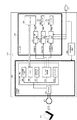
図1は、本発明の実施例1を示す情報処理装置の一例を示すブロック図である。
図1において、200は、本発明の情報処理装置としての画像形成装置(以下MFP;Multi Function Peripheral)である。なお、「MFP」は「複合機」ともいう。また、本発明の情報処理装置は、MFPに限定されるものではなく、プリンタやスキャナ等の他の情報処理装置であってもよい。
FIG. 1 is a block diagram illustrating an example of an information processing apparatus according to the first embodiment of this invention.
In FIG. 1,
MFP200は、プリンタ、スキャナ、コピー、FAXなどの複数の機能を備える。MFP200は、近接無線通信部300、デバイス部400、近接無線部電源202を有する。100は携帯端末で、MFP200の近接無線通信部300と近接無線通信可能な外部機器である。近接無線部電源202は、外部の交流電源(AC)から近接無線通信部300へ電力を供給する電源生成部である。
The MFP 200 has a plurality of functions such as a printer, a scanner, a copy, and a FAX. The MFP 200 includes a proximity
近接無線通信部300は、NFC(Near Field Communication)である。また、携帯端末100は、NFCインタフェースを有し、該NFCインタフェースを用いて、近接無線通信部300と通信を行う。
The near
以下、近接無線通信部300について説明する。
近接無線通信部300において、301はNFC通信アンテナ(以下、アンテナ)である。303はRF(Radio Frequency)回路で、NFC通信のための高周波回路である。302は通信制御部で、アンテナ301に近接する携帯端末100と通信を行う。また、通信制御部302は、コントローラ部404とも通信を行う。
Hereinafter, the close proximity
In the close proximity
305は近接通信メモリで、不揮発性のメモリである。近接通信メモリ305には、ネットワーク設定値、アドレス帳データ、仕向け国情報等を含む情報が格納されている。306はCPUである。CPU306は、CPU306に内蔵されているROM(不図示)に格納されたプログラムを読み込むことにより動作する。307は、後述する図3に示すような通電管理テーブルが予め書き込まれた不揮発性のメモリである。308はデバイス制御部で、出力する信号(起動信号1〜3)によってデバイス部400の電源の出力制御を行う。309はワークメモリである。
A
次に、デバイス部400について説明する。
デバイス部400において、404は、MFP200のコントローラ部である。405はプリンタ部、406はリーダ部である。
Next, the
In the
コントローラ部404は、CPU、ROM、RAM、HDD、さらに、近接無線通信部300、プリンタ部405、リーダ部406及び不図示のネットワークI/Fや操作部等と接続する各種インタフェースを備えるCPUボードである。コントローラ部404は、内部のCPUがROMやHDD等に格納されたプログラムを実行することにより、MFP200全体を制御する。
The
401は、コントローラ部404への電源供給部(コントローラ部電源)であり、起動信号1に応じて非常夜電力をコントローラ部404へ供給する。402はプリンタ部405への電源供給部(プリンタ電源)で、起動信号2に応じて電力をプリンタ部405へ供給する。403はリーダ部406への電源供給部(リーダ電源)で、起動信号3に応じて電力をリーダ部406へ供給する。
以下、MFP200の電力状態を説明する。
MFP200は、スタンバイ状態と、スタンバイ状態より省電力のスリープ状態(省電力状態)を切り替えて動作する。
Hereinafter, the power state of the MFP 200 will be described.
The MFP 200 operates by switching between a standby state and a power-saving sleep state (power-saving state) from the standby state.
スリープ状態では、近接無線部電源202が電力を近接無線通信部300に供給している。電源供給部401、402、403による非常夜電力の供給は停止しており、各起動信号1、起動信号2、起動信号3の入力に応じて、非常夜電力を出力できるように待機している状態である。
In the sleep state, the proximity wireless
なお、電源供給部401は、上述した非常夜電力を供給する非常夜電源部と、常夜電力を供給する常夜電源部を有する。電源供給部401の常夜電源部は、スリープ状態でも動作しており、常夜電力をコントローラ部404に供給する。スリープ状態では、コントローラ部404は常夜電力により動作し、スリープ復帰要因の発生を監視する。
The
なお、スリープ復帰要因は、例えば、図示しないスリープ解除ボタンの入力等や、図示しないネットワークインタフェースでのジョブ受信等である。コントローラ部404は、スリープ復帰要因の発生を検知すると、スリープ復帰したことを、CPU306に通知する。
The sleep return factor is, for example, input of a sleep release button (not shown) or job reception at a network interface (not shown). When the
スタンバイ状態は、近接無線通信部300およびデバイス部400の両方が通電されている状態である。なお、スタンバイ中には、電源供給部401の非常夜電源部が非常夜電力をコントローラ部404に供給している。電源オフ状態は、近接無線通信部300およびデバイス部400の両方が通電されていない状態である。なお、近接無線通信部300に電力が供給されるとCPU306が起動し、図示しないCPU306内部のプログラムROMを読み込んで動作を開始する。
The standby state is a state where both the proximity
以下、図2を用いて実施例1におけるCPU306の動作を説明する。
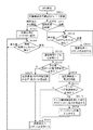
図2は、実施例1におけるCPU306の動作の一例を示すフローチャートである。なお、このフローチャートの処理は、CPU306がCPU306に内蔵されているROMに格納されたプログラムを読み込んで実行することにより実現される。
Hereinafter, the operation of the
FIG. 2 is a flowchart illustrating an example of the operation of the
MFP200側では、CPU306が起動したときに、S201において、近接無線通信部300をP2P(peer to peer)モードでの待機状態とする。次に、S202において、CPU306は、携帯端末100からのコマンドの受信を待つ。
On the
ユーザは携帯端末100からMFP200へ設定を行う(又はMFP200から情報を取得する)場合、携帯端末100において所定のアプリケーションを起動する。これによって、携帯端末100のNFCがP2Pモードとなる。この状態で、ユーザは動作を指示して、MFP200のアンテナ301へ携帯端末100を翳す(かざす)。これにより、携帯端末100と近接無線通信部300との通信が可能となる。なお、携帯端末100側の処理については後述する図7で示す。
When the user performs settings from the
CPU306は、携帯端末100からのコマンドを受信したと判定した場合(S202で「受信」の場合)、S203において、不揮発性のメモリ307に記憶される通電管理テーブル(図3に例示)を参照する。ここで、図3を用いて、通電管理テーブルについて説明する。
When the
図3は、実施例1における通電管理テーブルの一例を示す図である。
図3に示すように、実施例1の通電管理テーブルでは、携帯端末100から受信した要求データ毎(コマンド毎)に、通電して起動すべきMFP200のデバイス(モジュール(部位))を対応付けて記憶管理している。なお、図3はあくまで一例であり、本発明を限定するものではない。CPU306は、携帯端末100から受信したコマンドに応じて、このような通電管理テーブルを参照して、MFP200の各部位への通電の有無を決定し、該通電すべきと決定した部位への電力を供給する制御を行うことができる。
FIG. 3 is a diagram illustrating an example of an energization management table in the first embodiment.
As illustrated in FIG. 3, in the energization management table of the first embodiment, each request data received from the mobile terminal 100 (for each command) is associated with a device (module (part)) of the
以下、図2のフローチャートの説明に戻る。
次に、S204において、CPU306は、上記携帯端末100から受信したコマンドと通電管理テーブルに基づいて、デバイス部400への電源供給が必要かどうかを判定する。
The description returns to the flowchart of FIG.
In step S <b> 204, the
ここで、「スリープ時にMFPへネットワーク設定を行う」場合を例に説明する。
CPU306は、ネットワーク設定値の設定を要求するコマンドを受信した場合には、通電管理テーブルをもとに、デバイス部400への電源供給が不要と判定する。なお、ネットワーク設定値の設定を要求する場合、不揮発の近接通信メモリ305への読み書きだけとなる。上記S204において、デバイス部400への電源供給が不要と判定した場合(S204でNoの場合)、CPU306は、S205に処理を移行する。
Here, a case where “perform network setting for MFP during sleep” will be described as an example.
When the
S205において、CPU306は、携帯端末100から受信したコマンドに対応して不揮発の近接通信メモリ305内の情報を読み出す、又は、不揮発の近接通信メモリ305に情報を書き込む。例えば、上記ネットワーク設定値の設定を要求するコマンドを受信した場合、S205において、CPU306が、携帯端末100から受信したネットワーク設定値を不揮発の近接通信メモリ305に書き込む。
In step S <b> 205, the
上記S205の読み出し処理(又は書き込み処理)が終了すると、CPU306は、S206において、上記受信したコマンドのレスポンスとして、上記読み出したデータ(又は書き込みが終了したこと)を携帯端末100へ送信し、S201に処理を移行する。
When the reading process (or writing process) in S205 ends, the
なお、MFP200がスリープ中に、近接通信メモリ305に書き込まれた情報、例えば、ネットワーク設定値、アドレス帳データ、仕向け国情報等は、MFP200がスタンバイモードに復帰した際に、コントローラ部404内の記憶装置に格納される。これにより、MFP200のスリープ時に携帯端末100から行った設定が、MFP200本体へ反映されることとなる。また、MFP200がスタンバイ中に、例えば、ネットワーク設定値、アドレス帳データ、仕向け国情報等の設定変更等がなされた場合、これらの変更は、少なくともMFP200がスリープに移行するまでに、近接通信メモリ305に反映される。
Information written in the
次に、「スリープ時にプリンタログを取得する」場合を例に説明する。
CPU306は、携帯端末100からプリンタログを取得するコマンドを受信した場合には、通電管理テーブルをもとに、プリンタログを取得するためにコントローラ部404とプリンタ部405へ電力供給が必要と判定する。上記S204において、デバイス部400への電源供給が必要と判定した場合(S204でYesの場合)、CPU306は、S207に処理を移行する。
Next, a case of “acquiring a printer log during sleep” will be described as an example.
When the
S207において、CPU306は、デバイス制御部308に対して、通電管理テーブルで起動すべきデバイスに記載されているデバイスを起動するように指示する。上記「スリープ時にプリンタログを取得する」場合、CPU306は、デバイス制御部308に対して、電源供給部401、電源供給部402を起動させるための起動信号1、起動信号2を出力するように指示する。これにより、コントローラ部404とプリンタ部405が起動する。
In step S <b> 207, the
コントローラ部404が起動すると、S208において、CPU306は、コントローラ部404に、プリンタログの取得を指示する。この指示に応じて、コントローラ部404は、プリンタ部405と通信を行って動作のログ(プリンタログ)を取得し、該取得したプリンタログをCPU306へ送出する。上記S208の処理が終了すると、CPU306は、S206において、上記受信したコマンドのレスポンスとして、上記取得したデータを携帯端末100へ送信し、S201に処理を移行する。
When the
このように、MFP200内の近接無線通信部300内の近接通信メモリ305に記憶できる少量のデータの交換については、MFP200のデバイス部400を起動せず、外部リーダライタ機器との通信で行うことができる。なお、この方法で実行できる処理は、例えば、ネットワーク設定、アドレス帳の読み取り/書き込み設定、印刷枚数カウンタの読み取り、仕向け地の書き込み設定、ユーザモードの書き込み設定等である。
As described above, a small amount of data that can be stored in the near
一方、近接無線通信部300内の近接通信メモリ305に記憶できないデータ(例えば、ログ、温度等の各種リアルタイムデータ、メンテ用画像形成プロセスデータ等)については、MFP200内部の対応するモジュール(部位)を起動して取得する。なお、上記のMFP200を起動する指示に対してMFP200が起動できなかった場合は、MFP200が故障している可能性があるため、携帯端末100へはその旨を通知する。
On the other hand, for data that cannot be stored in the
以下、図7を参照して、携帯端末100側の処理について説明する。
図7は、携帯端末100側の処理の一例を示すフローチャートを示す。この処理は、携帯端末100の図示しないCPUが図示しないROM等に記憶されたプログラムを読み出して実行することにより実現される。
Hereinafter, the process on the
FIG. 7 is a flowchart illustrating an example of processing on the
S701において、携帯端末100のCPU(不図示)は、ユーザによるMFP200へ設定を行うためのアプリケーションの起動指示を検知すると、該アプリケーションを起動する。なお、上記アプリケーションのプログラムは、携帯端末100のROM(不図示)等に格納されている。
In step S <b> 701, when a CPU (not shown) of the
次に、S702において、携帯端末100のCPUは、MFP200への要求を入力する入力画面を表示し、S703において、ユーザによるMFP200への指示の入力を待機する。そして、ユーザによるMFP200への指示が入力されたと判定した場合(S703でYesの場合)、携帯端末100のCPUは、S704において、NFCインタフェースをP2Pモードで動作させる。
In step S <b> 702, the CPU of the
次に、S705において、携帯端末100のCPUは、MFP200との通信の成立を待つ。そして、MFP200との通信が成立したと判定した場合(S705でYesの場合)、携帯端末100のCPUは、S706に処理を進める。
In step S <b> 705, the CPU of the
S706において、携帯端末100のCPUは、ユーザにより入力されたMFP200への指示に対応するコマンドを、MFP200へ送信する。次に、S707において、携帯端末100のCPUは、MFP200からの応答を待つ。そして、MFP200からの応答があると(S706でYesの場合)、携帯端末100のCPUは、S708において、MFP200からの応答を受信し、本フローチャートの処理を終了する。
In step S <b> 706, the CPU of the
なお、S706〜S708の処理時間は、携帯端末100からMFP200へ送信されるコマンドによって変わる。すなわち、MFP200のデバイス部400を起動してデバイス部400から情報を入手する場合は長くなり、MFP200のデバイス部400を起動せずにMFP200から情報を入手する場合は短くなる。
Note that the processing time of S706 to S708 varies depending on the command transmitted from the
近距離無線通信を用いて画像形成装置から取得あるいは設定するデータについて、データによって画像形成装置本体を起動することが必要な場合と不要な場合がある。本実施例では、近距離無線通信部300がコマンドに対応するテーブルをもち、MFP200本体(デバイス部400等)を通電するか通電しない、あるいは通電する場合はどのデバイスに通電するかの判定を行う。本実施例によれば、操作者は、スリープ状態という省電力状態で待機している画像形成装置に対して、携帯端末を操作して翳すだけで、画像形成装置から必要な情報を取得あるいは設定することができる。その際、必要な場合のみ自動で画像形成装置本体を起動し、不必要な場合には画像形成装置本体を起動することなく省電力状態のままで、必要な情報の取得や設定を行うことができる。よって、操作者の誤操作等により、不必要に画像形成装置本体を起動して余分な電力を消費することがない。また、操作者は近距離無線通信を用いて動作を指示するだけでよく、操作者の利便性を向上させることもできる。
With respect to data acquired or set from the image forming apparatus using short-range wireless communication, it may or may not be necessary to start the image forming apparatus main body according to the data. In this embodiment, the short-range
上述の実施例1では、近接無線通信部300は、スタンバイ状態及びスリープ状態の双方の状態において外部電源に基づく電力により駆動する構成を説明した。実施例2では、近接無線通信部300は、スタンバイ状態では外部電源に基づく電力により駆動し、前記スリープ状態では携帯端末100からの電波により誘起される電力で駆動する。以下、実施例2について詳細に説明する。なお、実施例2では、実施例1と同一の構成については説明を省略し、異なる部分のみ説明する。
In the first embodiment described above, the configuration in which the proximity
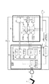
図4は、本発明の実施例2を示す情報処理装置の一例を示すブロック図である。なお、図1と同一のものには同一の符号を付してある。
図4において、201は電源切り替え部で、近接無線部電源202によりACから生成された電力(B入力)とアンテナ301から誘起した電力(A入力)とを切り替えて、近接無線通信部300へ供給するためのものである。電源切り替え部201は、デバイス制御部308からの切替信号に応じて、供給源(A入力、B入力)を切り替え選択する。304は電源生成部で、アンテナ301に誘起した電力からDC電源(A入力)を生成するためのものである。
FIG. 4 is a block diagram illustrating an example of an information processing apparatus according to the second embodiment of this invention. In addition, the same code | symbol is attached | subjected to the same thing as FIG.
In FIG. 4,
スタンバイ状態では、電源切り替え部201では電力供給源としてB入力が選択されており、近接無線部電源202からの電力(B入力)を近接無線通信部300に供給されている。スリープ状態に移行する場合に、コントローラ部404等からの制御により、電源切り替え部201は電力供給源をB入力からA入力に切り替える。即ち、スリープ状態では、電源切り替え部201はA入力が近接無線通信部300への供給源となるよう選択されている。したがって、スリープ状態では、近接無線通信部300は、リーダライタ動作している携帯端末100からアンテナ301へ誘起する電力で動作する。
In the standby state, the B input is selected as the power supply source in the power
MFP200がスリープ状態では、電源供給部401の非常夜電源部、電源供給部402、403、近接無線部電源202は停止しているがACは通電されており、起動信号に応じて電力を出力できるように待機している状態である。なお、スリープ状態でも、電源供給部401の常夜電源部は動作しており、コントローラ部404は、スリープ復帰要因の発生を監視している。
When the
コントローラ部404は、スリープ復帰要因の発生を検知すると、近接無線部電源202に起動信号(不図示)を出力し、近接無線部電源202を動作させるとともに、電源切り替え部201の電力供給源をA入力からB入力に切り替える。さらに、近接無線部電源202のCPU306が起動すると、コントローラ部404は、スリープ復帰したことを、CPU306に通知する。なお、近接無線通信部300に電力が供給されると、CPU306が起動し、図示しないCPU内部のプログラムROMを読み込んで動作を開始する。
When the
以下、図5を用いて実施例2におけるCPU306の動作を説明する。
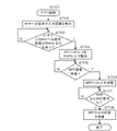
図5は、実施例2におけるCPU306の動作の一例を示すフローチャートである。なお、このフローチャートの処理は、CPU306がCPU306に内蔵されているROMに格納されたプログラムを読み込んで実行することにより実現される。
Hereinafter, the operation of the
FIG. 5 is a flowchart illustrating an example of the operation of the
MFP200側では、CPU306が起動したときに、S501において、近接無線通信部300をP2Pモードでの待機状態とする。次に、S502において、CPU306は、CPU306の起動要因を判別する。CPU306は、コントローラ部404からの通知により起動要因を判別可能である。コントローラ部404からスリープ復帰の通知があった場合には「スリープ復帰」と判断し、該通知がなかった場合には「携帯端末からの誘起」と判断する。
On the
CPU306は、CPU306の起動要因が携帯端末100からの誘起であると判定した場合(S502で「携帯端末からの誘起」の場合)、S503に処理を進める。S503では、CPU306は、携帯端末からの誘起による起動を示すフラグを、ワークメモリ309へ記録し、S504に処理を進める。S504において、CPU306は、携帯端末100からのコマンドを待つ。
If the
ユーザは携帯端末100からMFP200へ設定を行う(又は情報を取得する)場合、所定のアプリケーションを起動する。これによって、携帯端末100のNFCがP2P(peer to peer)モードとなる。この状態で、動作を指示して、MFP200のアンテナ301へ携帯端末100を翳す。これにより、携帯端末100と近接無線通信部300との通信が可能となる。なお、携帯端末100側の処理については図7に示した通りである。
When the user performs setting (or obtains information) from the
CPU306は、携帯端末100からのコマンドを受信したと判定した場合(S504で受信の場合)、CPU306は、S505において、不揮発性のメモリ307に記憶される通電管理テーブルを参照する。なお、実施例2の不揮発性のメモリ307には、図6に示すような通電管理テーブルが予め書き込まれている。ここで、図6を用いて、実施例2の通電管理テーブルについて説明する。
When the
図6は、実施例2における通電管理テーブルの一例を示す図である。
図6に示すように、実施例1の通電管理テーブルでは、携帯端末100から受信した要求データ毎に、起動すべきMFP200のデバイスを記憶管理している。実施例2では、例えば、プリンタログ、プリンタプロセス値、リーダログ、リーダセンサ補正値等の取得の場合には、起動すべきデバイスに、近接無線通信部300が含まれる。なお、図6はあくまで一例であり、本発明を限定するものではない。
FIG. 6 is a diagram illustrating an example of the energization management table in the second embodiment.
As illustrated in FIG. 6, in the energization management table of the first embodiment, the
以下、図5のフローチャートの説明に戻る。
次に、S506において、CPU306は、上記携帯端末100から受信したコマンドと通電管理テーブルに基づいて、近接無線通信部300への電源供給が必要かどうかを判定する。
Returning to the flowchart of FIG.
In step S <b> 506, the
ここで、「スリープ時にMFPへネットワーク設定を行う」場合を例に説明する。
CPU306は、ネットワーク設定値の設定を要求するコマンドを受信した場合には、通電管理テーブルをもとに、近接無線通信部300への電源供給が不要と判定する。なお、ネットワーク設定値の設定を要求する場合、不揮発の近接通信メモリ305への読み書きだけとなる。上記S506において、近接無線通信部300への電源供給が不要と判定した場合(S506でNoの場合)、CPU306は、S507に処理を移行する。
Here, a case where “perform network setting for MFP during sleep” will be described as an example.
When the
S507において、CPU306は、携帯端末100から受信したコマンドに対応して不揮発の近接通信メモリ305内の情報を読み出す、又は、不揮発の近接通信メモリ305に情報を書き込む。例えば、上記ネットワーク設定値の設定を要求するコマンドを受信した場合、S507において、CPU306が、携帯端末100から受信したネットワーク設定値を不揮発の近接通信メモリ305に書き込む。
In step S <b> 507, the
上記S507の読み出し処理(又は書き込み処理)が終了すると、CPU306は、S508において、上記受信したコマンドのレスポンスとして、上記読み出したデータ(又は書き込みが終了したこと)を携帯端末100へ送信し、S504に処理を移行する。
When the reading process (or writing process) in S507 ends, the
次に、「スリープ時にプリンタログを取得する」場合を例に説明する。
CPU306は、携帯端末100からプリンタログを取得するコマンドを受信した場合には、通電管理テーブルをもとに、プリンタログを取得するために近接無線通信部300、コントローラ部404、及びプリンタ部405へ電力供給が必要と判定する。上記S506において、近接無線通信部300への電源供給が必要と判定した場合(S506でYesの場合)、CPU306は、S509に処理を移行する。
Next, a case of “acquiring a printer log during sleep” will be described as an example.
When the
S509において、CPU306は、デバイス制御部308に対して、電源切り替え部201の電力供給元をB入力へ切り替え、近接無線部電源202によりAC入力から生成した電源を近接無線通信部300へ供給するように指示する。
In step S <b> 509, the
次に、S509において、CPU306は、上記携帯端末100から受信したコマンドと通電管理テーブルに基づいて、デバイス部400への電源供給が必要かどうかを判定する。
In step S <b> 509, the
次に、S510において、CPU306は、デバイス部400への電源供給が必要かどうかを判定する。上述のように、携帯端末100からプリンタログを取得するコマンドの場合、CPU306は、デバイス部400(ここではコントローラ部404、及びプリンタ部405)へ電力供給が必要と判定する。上記S510において、デバイス部400への電源供給が必要と判定した場合(S510でYesの場合)、CPU306は、S511に処理を移行する。
Next, in S510, the
S511において、CPU306は、デバイス制御部308に対して、通電管理テーブルで起動すべきと記載されていたデバイスを起動するように指示する。上記「スリープ時にプリンタログを取得する」場合、CPU306は、デバイス制御部308に対して、電源供給部401、402を起動させるための起動信号1、起動信号2を出力するように指示する。
In step S <b> 511, the
コントローラ部404が起動すると、S512において、CPU306は、コントローラ部404に、プリンタログの取得を指示する。この指示に応じて、コントローラ部404は、プリンタ部405と通信を行って動作のログ(プリンタログ)を取得し、該取得したプリンタログをCPU306へ送出する。上記S512の処理が終了すると、CPU306は、S508において、上記受信したコマンドのレスポンスとして、上記取得したデータを携帯端末100へ送信し、S501に処理を移行する。
When the
また、上記S510にて、CPU306はデバイス部400への電源供給が必要ないと判定した場合(S510でNoの場合)、S508において、上記コマンドに対応する処理を行い、該コマンドのレスポンスを携帯端末100へ送信し、S504に移行する。
If the
次に「スリープ時に復帰ボタンを押された」場合を説明する。これは図示しない操作パネルにあるスリープ解除ボタンを操作することでもスリープから復帰する場合である。
CPU306は、CPU306の起動要因がスリープ復帰であると判定した場合(S502で「スリープ復帰」の場合)、図示しないステップにおいて、復帰ボタンから起動したことを示すフラグをワークメモリ309へ記録し、S513に処理を進める。S513では、CPU306は、デバイス制御部308に対して、デバイス部400の全電源(電源供給部401、402、403)を起動させるための起動信号1、起動信号2、起動信号3を出力するように指示する。これにより、デバイス部400(コントローラ部404、プリンタ部405、リーダ部406)が起動する。
Next, the case where “the return button is pressed during sleep” will be described. This is a case of returning from sleep by operating a sleep cancel button on an operation panel (not shown).
When the
次に、S513において、CPU306は、携帯端末100からのコマンドを待つ。そして、携帯端末100からのコマンドを受信したと判定した場合(S513で「受信」の場合)、CPU306は、S514において、上記コマンドに対応する処理を行い、該コマンドのレスポンスを携帯端末100へ送信し、S513に処理を移行する。
Next, in S513, the
以上示したように、実施例2では、スリープ状態において、近接無線部電源202からの近接無線通信部300への電力供給を停止する構成である。よって、実施例1の効果に加え、さらなる省電力を実現することができる等の効果を奏する。
As described above, the second embodiment is configured to stop power supply from the close proximity wireless communication
上記各実施例では、本発明をMFP、プリンタ等の画像形成装置に適用する場合を説明した。しかし、本発明は、近接無線通信部を有し、携帯端末100から情報取得又は設定を行うことができる情報処理装置であれば適用可能である。
In each of the above embodiments, the case where the present invention is applied to an image forming apparatus such as an MFP or a printer has been described. However, the present invention is applicable to any information processing apparatus that has a close proximity wireless communication unit and can acquire or set information from the
なお、上述した各種データの構成及びその内容はこれに限定されるものではなく、用途や目的に応じて、様々な構成や内容で構成されることは言うまでもない。
以上、一実施形態について示したが、本発明は、例えば、システム、装置、方法、プログラムもしくは記憶媒体等としての実施態様をとることが可能である。具体的には、複数の機器から構成されるシステムに適用しても良いし、また、一つの機器からなる装置に適用しても良い。
また、上記各実施例を組み合わせた構成も全て本発明に含まれるものである。
It should be noted that the configuration and contents of the various data described above are not limited to this, and it goes without saying that the various data and configurations are configured according to the application and purpose.
Although one embodiment has been described above, the present invention can take an embodiment as, for example, a system, apparatus, method, program, or storage medium. Specifically, the present invention may be applied to a system composed of a plurality of devices, or may be applied to an apparatus composed of a single device.
Moreover, all the structures which combined said each Example are also contained in this invention.
(他の実施例)
また、本発明は、以下の処理を実行することによっても実現される。即ち、上述した実施形態の機能を実現するソフトウェア(プログラム)を、ネットワーク又は各種記憶媒体を介してシステム或いは装置に供給し、そのシステム或いは装置のコンピュータ(またはCPUやMPU等)がプログラムを読み出して実行する処理である。
また、本発明は、複数の機器から構成されるシステムに適用しても、1つの機器からなる装置に適用してもよい。
本発明は上記実施例に限定されるものではなく、本発明の趣旨に基づき種々の変形(各実施例の有機的な組合せを含む)が可能であり、それらを本発明の範囲から除外するものではない。即ち、上述した各実施例及びその変形例を組み合わせた構成も全て本発明に含まれるものである。
(Other examples)
The present invention can also be realized by executing the following processing. That is, software (program) that realizes the functions of the above-described embodiments is supplied to a system or apparatus via a network or various storage media, and a computer (or CPU, MPU, or the like) of the system or apparatus reads the program. It is a process to be executed.
Further, the present invention may be applied to a system composed of a plurality of devices or an apparatus composed of a single device.
The present invention is not limited to the above embodiments, and various modifications (including organic combinations of the embodiments) are possible based on the spirit of the present invention, and these are excluded from the scope of the present invention. is not. That is, the present invention includes all the combinations of the above-described embodiments and modifications thereof.
100 携帯端末
300 近接無線通信部
305 近接通信メモリ
306 CPU
307 通電管理テーブル
400 デバイス部
404 コントローラ部
DESCRIPTION OF
307 Energization management table 400
Claims (9)
前記第2電力状態のときに、モバイル端末から出力された電波によって誘起される電力で動作し、前記モバイル端末と通信する、近距離無線通信部と、
前記情報処理装置の各部への電力供給を制御する電力制御手段と、を備え、
前記第2電力状態のときに、前記モバイル端末から第1タイプのコマンドを受信した場合には、前記第2電力状態のままで、前記近距離無線通信部は、前記コマンドに対する応答を前記モバイル端末に送信し、
前記第2電力状態のときに、前記モバイル端末から第2タイプのコマンドを受信した場合には、前記電力制御手段は、前記コマンドに対応する応答を送信するために必要なデバイスに電力が供給されるよう制御する、ことを特徴とする情報処理装置。 An information processing apparatus operable in a first power state and a second power state that consumes less power than the first power state,
A short-range wireless communication unit that operates with power induced by radio waves output from a mobile terminal and communicates with the mobile terminal in the second power state;
Power control means for controlling power supply to each part of the information processing apparatus,
When the first type command is received from the mobile terminal in the second power state, the short-range wireless communication unit remains in the second power state and sends a response to the command to the mobile terminal. To
When the second type command is received from the mobile terminal in the second power state, the power control unit supplies power to a device necessary for transmitting a response corresponding to the command. An information processing apparatus characterized by controlling the
前記近距離無線通信部は、前記テーブルと前記モバイル端末から受信したコマンドとに基づいて、電力を供給するデバイスを決定する、ことを特徴とする請求項1乃至3の何れか1項に記載の情報処理装置。 The short-range wireless communication unit includes a memory that stores a table in which a command transmitted from the mobile terminal is associated with a device that supplies power;
4. The device according to claim 1, wherein the short-range wireless communication unit determines a device that supplies power based on the table and a command received from the mobile terminal. 5. Information processing device.
前記第2電力状態のときに、モバイル端末から出力された電波によって誘起される電力で、近距離無線通信部を動作させるステップと、
前記第2電力状態のときに、前記モバイル端末から第1タイプのコマンドを受信した場合には、前記第2電力状態のままで、前記近距離無線通信部に、前記コマンドに対する応答を前記モバイル端末に送信させるステップと、
前記第2電力状態のときに、前記モバイル端末から第2タイプのコマンドを受信した場合には、前記コマンドに対応する応答を送信するために必要なデバイスに電力を供給するステップと、を有することを特徴とする情報処理装置の制御方法。 A control method for an information processing apparatus operable in a first power state and a second power state that consumes less power than the first power state,
Operating the short-range wireless communication unit with power induced by radio waves output from the mobile terminal in the second power state;
When the first type command is received from the mobile terminal in the second power state, the mobile terminal sends a response to the command to the short-range wireless communication unit while maintaining the second power state. Sending to
Supplying power to a device necessary for transmitting a response corresponding to the command when receiving a second type command from the mobile terminal in the second power state. A method for controlling an information processing apparatus.
Priority Applications (2)
| Application Number | Priority Date | Filing Date | Title |
|---|---|---|---|
| JP2013260812A JP6238723B2 (en) | 2013-12-18 | 2013-12-18 | Information processing apparatus, information processing apparatus control method, and program |
| US14/570,950 US9681383B2 (en) | 2013-12-18 | 2014-12-15 | Information processing apparatus, method for controlling information processing apparatus, and storage medium |
Applications Claiming Priority (1)
| Application Number | Priority Date | Filing Date | Title |
|---|---|---|---|
| JP2013260812A JP6238723B2 (en) | 2013-12-18 | 2013-12-18 | Information processing apparatus, information processing apparatus control method, and program |
Publications (3)
| Publication Number | Publication Date |
|---|---|
| JP2015116711A JP2015116711A (en) | 2015-06-25 |
| JP2015116711A5 JP2015116711A5 (en) | 2017-06-29 |
| JP6238723B2 true JP6238723B2 (en) | 2017-11-29 |
Family
ID=53370185
Family Applications (1)
| Application Number | Title | Priority Date | Filing Date |
|---|---|---|---|
| JP2013260812A Expired - Fee Related JP6238723B2 (en) | 2013-12-18 | 2013-12-18 | Information processing apparatus, information processing apparatus control method, and program |
Country Status (2)
| Country | Link |
|---|---|
| US (1) | US9681383B2 (en) |
| JP (1) | JP6238723B2 (en) |
Families Citing this family (6)
| Publication number | Priority date | Publication date | Assignee | Title |
|---|---|---|---|---|
| JP6507750B2 (en) * | 2015-03-19 | 2019-05-08 | ブラザー工業株式会社 | Image forming device |
| JP6443208B2 (en) * | 2015-04-28 | 2018-12-26 | 横河電機株式会社 | Wireless device, gateway device, and wireless communication system |
| US10474216B2 (en) * | 2015-12-16 | 2019-11-12 | Intel Corporation | Method and apparatus for providing power state information using in-band signaling |
| KR102408583B1 (en) * | 2018-02-22 | 2022-06-15 | 삼성전자주식회사 | Method and apparatus for operating multimodal of near field communications circuitry |
| JP7401234B2 (en) | 2019-09-25 | 2023-12-19 | 東芝テック株式会社 | Image forming apparatus and control method |
| WO2021112871A1 (en) * | 2019-12-06 | 2021-06-10 | Hewlett-Packard Development Company, L.P. | Induced current-based power supply control |
Family Cites Families (9)
| Publication number | Priority date | Publication date | Assignee | Title |
|---|---|---|---|---|
| JP2006054757A (en) * | 2004-08-13 | 2006-02-23 | Ts Photon:Kk | Information communication system by rfid tag with sub communication interface |
| JP2007267255A (en) * | 2006-03-29 | 2007-10-11 | Sharp Corp | Image processing apparatus |
| WO2009019735A1 (en) * | 2007-08-07 | 2009-02-12 | Fujitsu Limited | Response wireless device and its wireless communication method |
| JP2010093609A (en) * | 2008-10-09 | 2010-04-22 | Murata Machinery Ltd | Digital composite machine |
| US8855563B2 (en) * | 2010-07-07 | 2014-10-07 | Panasonic Intellectual Property Corporation Of America | Communication apparatus and communication method |
| EP2597779B1 (en) * | 2010-07-23 | 2016-10-12 | Panasonic Intellectual Property Corporation of America | Nfc communication apparatus and method for controlling same |
| WO2012073512A1 (en) * | 2010-11-30 | 2012-06-07 | パナソニック株式会社 | Communication device and communication method |
| US8903312B2 (en) * | 2011-11-28 | 2014-12-02 | Qualcomm Incorporated | Modified connection establishment for reducing power consumption in near field communication systems |
| WO2014057634A1 (en) * | 2012-10-10 | 2014-04-17 | パナソニック株式会社 | Communication device, communication system, mobile terminal, program and server |
-
2013
- 2013-12-18 JP JP2013260812A patent/JP6238723B2/en not_active Expired - Fee Related
-
2014
- 2014-12-15 US US14/570,950 patent/US9681383B2/en not_active Expired - Fee Related
Also Published As
| Publication number | Publication date |
|---|---|
| JP2015116711A (en) | 2015-06-25 |
| US9681383B2 (en) | 2017-06-13 |
| US20150173020A1 (en) | 2015-06-18 |
Similar Documents
| Publication | Publication Date | Title |
|---|---|---|
| JP6238723B2 (en) | Information processing apparatus, information processing apparatus control method, and program | |
| US11025785B2 (en) | Apparatus, control method, and non-transitory computer readable storage medium that cause a device to print an image based on a state of the apparatus and a user operation | |
| JP6239864B2 (en) | COMMUNICATION DEVICE, ITS CONTROL METHOD, AND PROGRAM | |
| US8374515B2 (en) | Image forming system, image forming apparatus, and computer readable medium | |
| US20150062643A1 (en) | Wireless communication apparatus, wireless communication method, and storage medium | |
| JP6727798B2 (en) | Information processing apparatus, control method thereof, and program | |
| JP6552582B2 (en) | System, information processing apparatus, and execution apparatus | |
| JP6452313B2 (en) | COMMUNICATION DEVICE, ITS CONTROL METHOD, PROGRAM | |
| JP2013186505A (en) | Information processing apparatus and system, and control methods for the same, and program | |
| US9915999B2 (en) | Information processing apparatus, method for controlling the same, and storage medium | |
| JP2015184917A (en) | System, information processing apparatus, control method of the information processing apparatus, and program | |
| JP2015231155A (en) | Communication system, information processing device and control method thereof, and program | |
| EP2696565B1 (en) | Power control of an image processing apparatus | |
| JP6680186B2 (en) | Electronic equipment and power control program | |
| JP2014045302A (en) | Image processing device, control method of image processing device, and program | |
| JP6700812B2 (en) | Processing device, processing method, and program | |
| JP2015106369A (en) | Image formation system, communication control method and program | |
| JP5973512B2 (en) | Device information acquisition program, device information acquisition system, and device information acquisition method | |
| JP2010194884A (en) | Image forming apparatus and program | |
| JP7129313B2 (en) | PRINTING DEVICE, PRINTING SYSTEM, CONTROL METHOD AND PROGRAM | |
| JP7191899B2 (en) | Information processing device and its control method | |
| JP2018199219A (en) | Image forming apparatus | |
| JP2015003451A (en) | Image formation device, control method for image formation device, and program | |
| JP2015002434A (en) | Image forming apparatus, control method for image forming apparatus, and program | |
| JP2020022172A (en) | Program, control method of communication terminal, and communication terminal |
Legal Events
| Date | Code | Title | Description |
|---|---|---|---|
| A621 | Written request for application examination |
Free format text: JAPANESE INTERMEDIATE CODE: A621 Effective date: 20161214 |
|
| RD03 | Notification of appointment of power of attorney |
Free format text: JAPANESE INTERMEDIATE CODE: A7423 Effective date: 20161214 |
|
| A521 | Request for written amendment filed |
Free format text: JAPANESE INTERMEDIATE CODE: A523 Effective date: 20170522 |
|
| A977 | Report on retrieval |
Free format text: JAPANESE INTERMEDIATE CODE: A971007 Effective date: 20170919 |
|
| TRDD | Decision of grant or rejection written | ||
| A01 | Written decision to grant a patent or to grant a registration (utility model) |
Free format text: JAPANESE INTERMEDIATE CODE: A01 Effective date: 20171003 |
|
| A61 | First payment of annual fees (during grant procedure) |
Free format text: JAPANESE INTERMEDIATE CODE: A61 Effective date: 20171031 |
|
| R151 | Written notification of patent or utility model registration |
Ref document number: 6238723 Country of ref document: JP Free format text: JAPANESE INTERMEDIATE CODE: R151 |
|
| LAPS | Cancellation because of no payment of annual fees |