EP2696565B1 - Power control of an image processing apparatus - Google Patents
Power control of an image processing apparatus Download PDFInfo
- Publication number
- EP2696565B1 EP2696565B1 EP13179086.7A EP13179086A EP2696565B1 EP 2696565 B1 EP2696565 B1 EP 2696565B1 EP 13179086 A EP13179086 A EP 13179086A EP 2696565 B1 EP2696565 B1 EP 2696565B1
- Authority
- EP
- European Patent Office
- Prior art keywords
- print device
- job
- power
- cpu
- image processing
- Prior art date
- Legal status (The legal status is an assumption and is not a legal conclusion. Google has not performed a legal analysis and makes no representation as to the accuracy of the status listed.)
- Not-in-force
Links
- 238000012545 processing Methods 0.000 title claims description 60
- 238000000034 method Methods 0.000 claims description 8
- 238000004590 computer program Methods 0.000 claims 1
- 230000006870 function Effects 0.000 description 26
- 230000015654 memory Effects 0.000 description 19
- 238000007639 printing Methods 0.000 description 5
- 238000006243 chemical reaction Methods 0.000 description 3
- 238000003756 stirring Methods 0.000 description 3
- 230000005540 biological transmission Effects 0.000 description 2
- 238000004891 communication Methods 0.000 description 2
- 238000010586 diagram Methods 0.000 description 2
- 230000002093 peripheral effect Effects 0.000 description 2
- 230000003321 amplification Effects 0.000 description 1
- 230000008859 change Effects 0.000 description 1
- 230000003247 decreasing effect Effects 0.000 description 1
- 238000011161 development Methods 0.000 description 1
- 238000004134 energy conservation Methods 0.000 description 1
- 238000005265 energy consumption Methods 0.000 description 1
- 238000012986 modification Methods 0.000 description 1
- 230000004048 modification Effects 0.000 description 1
- 238000003199 nucleic acid amplification method Methods 0.000 description 1
- 230000003287 optical effect Effects 0.000 description 1
- 230000004044 response Effects 0.000 description 1
- 230000004043 responsiveness Effects 0.000 description 1
- 239000004065 semiconductor Substances 0.000 description 1
- 239000007787 solid Substances 0.000 description 1
- 238000012546 transfer Methods 0.000 description 1
- 238000004148 unit process Methods 0.000 description 1
Images
Classifications
-
- G—PHYSICS
- G06—COMPUTING; CALCULATING OR COUNTING
- G06F—ELECTRIC DIGITAL DATA PROCESSING
- G06F3/00—Input arrangements for transferring data to be processed into a form capable of being handled by the computer; Output arrangements for transferring data from processing unit to output unit, e.g. interface arrangements
- G06F3/12—Digital output to print unit, e.g. line printer, chain printer
- G06F3/1201—Dedicated interfaces to print systems
- G06F3/1202—Dedicated interfaces to print systems specifically adapted to achieve a particular effect
- G06F3/1218—Reducing or saving of used resources, e.g. avoiding waste of consumables or improving usage of hardware resources
- G06F3/1221—Reducing or saving of used resources, e.g. avoiding waste of consumables or improving usage of hardware resources with regard to power consumption
-
- G—PHYSICS
- G03—PHOTOGRAPHY; CINEMATOGRAPHY; ANALOGOUS TECHNIQUES USING WAVES OTHER THAN OPTICAL WAVES; ELECTROGRAPHY; HOLOGRAPHY
- G03G—ELECTROGRAPHY; ELECTROPHOTOGRAPHY; MAGNETOGRAPHY
- G03G15/00—Apparatus for electrographic processes using a charge pattern
- G03G15/50—Machine control of apparatus for electrographic processes using a charge pattern, e.g. regulating differents parts of the machine, multimode copiers, microprocessor control
- G03G15/5004—Power supply control, e.g. power-saving mode, automatic power turn-off
-
- G—PHYSICS
- G06—COMPUTING; CALCULATING OR COUNTING
- G06F—ELECTRIC DIGITAL DATA PROCESSING
- G06F3/00—Input arrangements for transferring data to be processed into a form capable of being handled by the computer; Output arrangements for transferring data from processing unit to output unit, e.g. interface arrangements
- G06F3/12—Digital output to print unit, e.g. line printer, chain printer
- G06F3/1201—Dedicated interfaces to print systems
- G06F3/1202—Dedicated interfaces to print systems specifically adapted to achieve a particular effect
- G06F3/1211—Improving printing performance
- G06F3/1212—Improving printing performance achieving reduced delay between job submission and print start
- G06F3/1213—Improving printing performance achieving reduced delay between job submission and print start at an intermediate node or at the final node
-
- G—PHYSICS
- G06—COMPUTING; CALCULATING OR COUNTING
- G06F—ELECTRIC DIGITAL DATA PROCESSING
- G06F3/00—Input arrangements for transferring data to be processed into a form capable of being handled by the computer; Output arrangements for transferring data from processing unit to output unit, e.g. interface arrangements
- G06F3/12—Digital output to print unit, e.g. line printer, chain printer
- G06F3/1201—Dedicated interfaces to print systems
- G06F3/1223—Dedicated interfaces to print systems specifically adapted to use a particular technique
- G06F3/1229—Printer resources management or printer maintenance, e.g. device status, power levels
-
- G—PHYSICS
- G06—COMPUTING; CALCULATING OR COUNTING
- G06F—ELECTRIC DIGITAL DATA PROCESSING
- G06F3/00—Input arrangements for transferring data to be processed into a form capable of being handled by the computer; Output arrangements for transferring data from processing unit to output unit, e.g. interface arrangements
- G06F3/12—Digital output to print unit, e.g. line printer, chain printer
- G06F3/1201—Dedicated interfaces to print systems
- G06F3/1278—Dedicated interfaces to print systems specifically adapted to adopt a particular infrastructure
- G06F3/1279—Controller construction, e.g. aspects of the interface hardware
-
- G—PHYSICS
- G06—COMPUTING; CALCULATING OR COUNTING
- G06K—GRAPHICAL DATA READING; PRESENTATION OF DATA; RECORD CARRIERS; HANDLING RECORD CARRIERS
- G06K15/00—Arrangements for producing a permanent visual presentation of the output data, e.g. computer output printers
- G06K15/40—Details not directly involved in printing, e.g. machine management, management of the arrangement as a whole or of its constitutive parts
- G06K15/4055—Managing power consumption, e.g. standby mode
- G06K15/406—Wake-up procedures
-
- H—ELECTRICITY
- H04—ELECTRIC COMMUNICATION TECHNIQUE
- H04N—PICTORIAL COMMUNICATION, e.g. TELEVISION
- H04N1/00—Scanning, transmission or reproduction of documents or the like, e.g. facsimile transmission; Details thereof
- H04N1/00885—Power supply means, e.g. arrangements for the control of power supply to the apparatus or components thereof
- H04N1/00888—Control thereof
- H04N1/00896—Control thereof using a low-power mode, e.g. standby
-
- H—ELECTRICITY
- H04—ELECTRIC COMMUNICATION TECHNIQUE
- H04N—PICTORIAL COMMUNICATION, e.g. TELEVISION
- H04N1/00—Scanning, transmission or reproduction of documents or the like, e.g. facsimile transmission; Details thereof
- H04N1/00912—Arrangements for controlling a still picture apparatus or components thereof not otherwise provided for
- H04N1/00928—Initialisation or control of normal start-up or shut-down, i.e. non failure or error related
-
- Y—GENERAL TAGGING OF NEW TECHNOLOGICAL DEVELOPMENTS; GENERAL TAGGING OF CROSS-SECTIONAL TECHNOLOGIES SPANNING OVER SEVERAL SECTIONS OF THE IPC; TECHNICAL SUBJECTS COVERED BY FORMER USPC CROSS-REFERENCE ART COLLECTIONS [XRACs] AND DIGESTS
- Y02—TECHNOLOGIES OR APPLICATIONS FOR MITIGATION OR ADAPTATION AGAINST CLIMATE CHANGE
- Y02D—CLIMATE CHANGE MITIGATION TECHNOLOGIES IN INFORMATION AND COMMUNICATION TECHNOLOGIES [ICT], I.E. INFORMATION AND COMMUNICATION TECHNOLOGIES AIMING AT THE REDUCTION OF THEIR OWN ENERGY USE
- Y02D10/00—Energy efficient computing, e.g. low power processors, power management or thermal management
Definitions
- the present invention relates to an image processing apparatus, a control method thereof, a program and a recording medium.
- an image processing apparatus including a printer and a multifunction peripheral (MFP) is provided (mounted) with a function for operating the apparatus with low power.
- MFP multifunction peripheral
- a function for powering off a device for example, a printer device and a scanner device, which is not in operation, is provided.
- a user determines a device required when a job operated by the printer device and the scanner device is input to the image processing apparatus, and then powers on the device, so as to reduce the power consumption in the waiting state.
- Japanese Patent Application Laid-Open No. 2011-215595 discusses that, when the image processing apparatus such as a printer is left with no power supplied for a long time, an initialization operation to be performed before printing requires more time than a normal initialization operation such as a stirring operation of toner.
- US-A-2010/226662 discloses an image forming apparatus having a network connecting portion, a control portion, and a status information storage portion.
- the control portion makes a determination of whether (a) to perform supply of power to the main body of the image forming apparatus and acquire a status information to transmit it through the network portion or (b) not to perform supply of power to the main body of the image forming apparatus, but to transmit through the network portion a status information that has been stored in the status information storage portion before the status request, and performs controls based on the determination.
- US-A-2010/257386 discloses an electronic device capable of decreasing power consumption.
- a multiple function apparatus including a power line communication function has a plurality of units.
- the multiple function apparatus also includes a device power supply unit for supplying power to the units independently.
- a power supply control unit outputs a power supply control signal in response to a state change of the multiple function apparatus and controls power supply to each unit.
- US-A-2006/203306 discloses a document reading apparatus including a scanner; an energy-saving power supply unit; an energy-saving control unit; a clock IC; an output compensation unit for updating digital conversion parameters including image signal amplification gain such that image data of a reference white board read by a CCD of the scanner are made into a proper value; and an output compensation controlling unit.
- the output compensation controlling unit reads time data when an operation mode is shifted from pause mode to waiting mode, stores the digital conversion parameters updated by the output compensation unit in a non-volatile memory, updates operation time with the present time if the elapsed time from a previous operation time stored in the non-volatile memory is equal to or greater than a setup value, and uses the digital conversion parameters stored in the non-volatile memory as they are, if the elapsed time from the previous operation time stored in the non-volatile memory is less than the setup value.
- US-A-2011/296219 discloses an image forming apparatus includes a communication interface receiving data; a buffer storing the data; a main system processing the stored data; a subsystem controlled by the main system to perform a function of the image forming apparatus; a system control unit; and a data processing unit.
- the system control unit switches an operation status mode of the image forming apparatus between a normal status mode and a deep sleep status mode.
- the data processing unit processes the data received from the buffer if the data is determined to be processable by the data processing unit and causes the system control unit to switch the operation status mode from the deep sleep status mode to the normal status mode if the received data is determined not to be processable by the data processing unit.
- US-A-2004/146313 discloses an image forming apparatus which is capable of responding to a status request with the minimum possible energy consumption even when the image forming apparatus is in a sleep state, to thereby achieve energy conservation.
- a main-chip microcomputer responds to an externally input status request when the image forming apparatus is in a normal standby mode, and enters an inoperative state where it does not respond to the externally input status request when the image forming apparatus is in a reduced power consumption mode.
- a further microcomputer responds to the externally input status request on behalf of the main-chip microcomputer when the image forming apparatus is in the reduced power consumption mode.
- the present invention is directed to an image processing apparatus.
- the present invention provides a system where, when an image processing apparatus receives a job, other than a print job, in a power-saving state, a device performing a print function is initialized to reduce a waiting time for performing a print job.
- an image processing apparatus as specified in claims 1 to 3.
- a method for controlling an image processing apparatus as claimed in claim 4.
- a program as specified in claim 5.
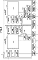
- Fig. 1 is a block diagram illustrating a configuration of an image processing apparatus illustrating a present exemplary embodiment. This example describes an MFP as one example of the image processing apparatus.
- a controller 1 includes a main board 100 and a sub board 120.
- the main board 100 includes a versatile central processing unit (CPU) system.
- a CPU 101 controls an entire board.
- a local area network (LAN) controller 102 communicates with an external device via a network.
- a memory 103 includes a random access memory (RAM) and the like, and is used by the CPU 101 as a work memory.
- a bus controller 104 has a bridge function with an external bus.
- a non-volatile memory 105 does not lose information even when a power is shut down.
- a real-time clock (RTC) 110 retains a time with a battery even when the power is shut down.
- a disk controller 106 controls a storage device.
- the storage device includes a flash disk solid state drive (SSD) 107, which is a storage device that has a relatively small capacity and is formed of a semiconductor device, and a hard disk device 6.
- SSD flash disk solid state drive
- a universal serial bus (USB) controller 108 controls a USB device.
- a USB memory 9, an operation unit 5 and the hard disk device 6 are externally connected to the main board 100.
- the storage device may not necessarily be the hard disk device 6, and any type of non-volatile device may be used as long as it is a non-volatile device.
- the sub board 120 includes a comparatively small versatile CPU system and an image processing hardware.
- a CPU 121 controls an entire board.
- a memory 123 is used by the CPU 121 as a work memory.
- a bus controller 124 has the bridge function with the external bus.
- a non-volatile memory 125 does not lose the information even when the power is shut down.
- An image processing processor 127 performs real-time digital image processing.
- a device controller 126 is also provided.
- An external scanner device 2 and an external printer device 4 transmit/receive digital image data via the device controller 126.
- a fax device 7 is directly controlled by the CPU 121.
- Power control units 109 and 128 manage to supply the power to units on the main board 100 and the sub board 120 respectively that require the power.
- the power switch 10 receives a user's operation to power on and off and, when the power switch is operated, the CPU 101 is interrupted. When the CPU 101 detects the interruption, it controls the power control unit 109 according to a state. Further, the CPU 121 detects the operation of the power switch 10 via the bus controllers 104 and 124, and then controls the power control unit 128.
- the CPU 101 and the CPU 121 include a great number of types of CPU peripheral hardware such as a chip set, a bus bridge, and a clock generator. However, since they do not require for the description, they are simply described and their block configuration does not limit the present invention. An example of copying processing by the controller 1 will be described below.
- the CPU 101 Upon reception of a user's instruction for copying an image via the operation unit 5, the CPU 101 transmits an image-reading direction to the scanner device 2 via the CPU 121 of the sub board 120.
- the scanner device 2 performs optical scanning on a paper document laid on a platen (not illustrated) or fed from an automatic document feeder (ADF). At this point, image data scanned by the scanner device 2 is converted into digital image data, and the converted digital image data is input into the image processing processor 127 via the device controller 126.
- ADF automatic document feeder
- the image processing processor 127 performs a direct memory access (DMA) transfer to the memory 123 via the CPU 121 to temporarily store the digital image data.
- DMA direct memory access
- the CPU 101 of the main board 100 instructs the printer device 4 to output an image via the CPU 121.
- the CPU 121 notifies the image processing processor 127 of an address of the image data stored in the memory 123.
- the image data stored in the memory 123 is transmitted to the printer device 4 via the image processing processor 127 and the device controller 126, and then the digital image data is printed on a sheet by the printer device 4.
- the CPU 101 stores in the hard disk device 6 the image data that has been stored in the memory 123 and, thus in subsequent printing, the image can be transmitted to the printer device 4 without receiving the image from the scanner device 2.
- the power control unit 128 performs control each device of the sub board 120 to stop power feeding (power supply) to the printer device 4 and the scanner device 2 in the waiting state of job processing until a job with a printing operation and a scanning operation is received from the user.
- the power control unit 128 When the CPU 101 receives the user's operation from the operation unit 5 and determines that the job requires the print function, the power control unit 128 performs control so that the power feeding to the printer device 4 can be started to perform an initialization operation of the printer device 4.
- the controller 1 When the initialization is completed, the job input by the user's operation is performed. When a predetermined time elapses after the job has been completed, the controller 1 is set to be in the waiting state of the job processing again.
- the power control unit 128 stops the power feeding to the printer device 4 and the scanner device 2, to which the power feeding is started when the job is performed.
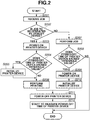
- Fig. 2 is a flowchart illustrating a control method of the image processing apparatus illustrating the present exemplary embodiment.
- This example describes control for performing initialization processing requiring stirring processing of developer stored in a development device included in the printer device 4, when a specified job such as a scanning job, a data transmission job, a box processing job, and a memory transmission job, which does not use the printer device 4, is performed according to the present exemplary embodiment.
- Each step can be realized by the CPUs 101 and 121 executing a control program loaded into the memories 103 and 123. Control will be described in detail below in which, even if a job is received when the power supply state to each device is set to be in the power-saving state and the job does not use a print function, when an elapsed time after the device performing the print function has moved to the power-saving state exceeds a predetermined threshold value, the power supply to the device performing the print function is resumed to perform predetermined initialization processing.
- a plurality of devices includes a device performing the print function, a device performing a scanner function, a device performing a sending function, and a device performing a box function for storing the data in a box.
- step S201 the user issues a job to the controller 1 via the operation unit 5 or the LAN controller 102.
- the CPU 101 of the main board 100 receives the issued job.
- step S202 the CPU 101 interprets the job received in step S201, and determines whether the job requires an operation of the printer device 4.
- the processing proceeds to step S203.
- the processing proceeds to step S207.
- the processing for determining whether to use the printer device 4 in step S202 corresponds to processing for determining whether to use the print function.
- step S203 the CPU 101 instructs the CPU 121 of the sub board 120 to power on the printer device 4.
- the CPU 121 powers on the printer device 4 via the device controller 126.
- step S204 the CPU 101 acquires a time from the RTC 110, and determines whether a time period of a power-off time of the printer device 4 exceeds a predetermined threshold value.
- the threshold value herein is a time period set according to a feature of the printer device 4 and a user' s usage environment, and may be any number of hours.
- step S205 the CPU 121 instructs the printer device 4 to perform the initialization via the device controller 126.
- the printer device 4 that has received the initialization instruction performs the above-described predetermined initialization processing, which is performed when the power-off time exceeds the threshold value. Since the processing for stirring the developer, for example, is included herein, a sufficient time is required to complete the initialization processing.
- step S206 the CPU 121 instructs the printer device 4 to perform printing via the device controller 126.
- the printer device 4 performs print processing based on the job, and notifies the CPU 121 of a print completion state after the printing is completed.
- step S207 the CPU 121 performs the job received in step S201.
- This job does not use the printer device 4 in step S202 and, for example, is the scanning job that uses only the scanner device 2.
- step S208 the CPU 101 acquires the time from the RTC 110, and determines whether the power-off time of the printer device 4 exceeds the threshold value.
- the power-off time corresponds to the elapsed time after the device performing the print function has been moved to the power-saving state.
- the threshold value is the time period set according to the feature of the printer device 4 and the user's usage environment, and may be any number of hours.
- step S209 the CPU 101 instructs the CPU 121 of the sub board 120 to power on the printer device 4.
- the CPU 121 powers on the printer device 4 via the device controller 126.
- step S210 the CPU 121 instructs the printer device 4 to perform the initialization via the device controller 126.
- the printer device 4 that has received the initialization instruction performs the predetermined initialization to be performed when the power-off time exceeds the predetermined time.
- step S210 executed by the CPU 121 the power is supplied to the device performing the print function.
- the processing in step S210 corresponds to processing for performing the predetermined initialization processing.
- step S211 the CPU 101 instructs the CPU 121 of the sub board 120 to power off the printer device 4.
- the CPU 121 powers off the printer device 4 via the device controller 126.
- step S212 the CPU 101 starts to measure the power-off time of the printer using the RTC 110.
- the measured value is referred to, at the time of determination as to whether the power-off time exceeds the threshold value in steps S204 and S208.
- the image processing apparatus corresponding to the time elapsing in the waiting state of the job, performs the initialization processing for performing the print function when the job other than the print job is required, thereby reducing the waiting time to perform the print job.
- the device If the device is not powered off in the waiting state, it is determined whether the power-off time exceeds the threshold value when the power supply is started to activate the device, or when the device is returned from a low-power state.
- the image processing apparatus to which the present exemplary embodiment is applied powers off the device even in the waiting state, the power-off time of the device cannot be determined only when the device is activated or when it is recovered from the low-power state.
- the image processing apparatus makes determination based on the determination in steps S204 and S208, when the job for starting the power supply to the device is performed. Further, according to the present exemplary embodiment, based on the determination in step S202, if it is determined that the power-off time exceeds the threshold value considering the initialization time of the device even when the job is performed in which the power is not normally supplied to the printer device 4, the power is supplied to the printer device 4 to perform the above-described initialization processing.
- the job that is not operated by the printer device 4 includes the function for transmitting fax operated only by the scanner, or storing the document in a reading storage, as described above.
- aspects of the present invention can also be realized by a computer of a system or apparatus (or devices such as a CPU or MPU) that reads out and executes a program recorded on a memory device (computer-readable medium) to perform the functions of the above-described embodiments, and by a method, the steps of which are performed by a computer of a system or apparatus by, for example, reading out and executing a program recorded on a memory device to perform the functions of the above-described embodiments.
- the program is provided to the computer for example via a network or from a recording medium of various types serving as the memory device (e.g., computer-readable medium).
- the system or apparatus, and the recording medium where the program is stored are included as being within the scope of the present invention.
Landscapes
- Engineering & Computer Science (AREA)
- Theoretical Computer Science (AREA)
- General Engineering & Computer Science (AREA)
- Physics & Mathematics (AREA)
- General Physics & Mathematics (AREA)
- Human Computer Interaction (AREA)
- Multimedia (AREA)
- Signal Processing (AREA)
- Microelectronics & Electronic Packaging (AREA)
- Accessory Devices And Overall Control Thereof (AREA)
- Facsimiles In General (AREA)
- Control Or Security For Electrophotography (AREA)
- Power Sources (AREA)
Description
- The present invention relates to an image processing apparatus, a control method thereof, a program and a recording medium.
- With an increasing energy-saving consciousness, an image processing apparatus including a printer and a multifunction peripheral (MFP) is provided (mounted) with a function for operating the apparatus with low power. Particularly, for the purpose of reducing power consumption during waiting, so in a waiting state waiting for a user's operation, a function for powering off a device, for example, a printer device and a scanner device, which is not in operation, is provided.
- Conventionally, responsiveness to the user's operation has been emphasized, and thus even in the waiting state, where the apparatus is not in operation, the device relating to image processing is kept power-on. A user determines a device required when a job operated by the printer device and the scanner device is input to the image processing apparatus, and then powers on the device, so as to reduce the power consumption in the waiting state.
- Upon reception of the user's operation, in a case where the device is powered on when the device required for the operation is determined, compared with a case where the power is always supplied to the device, more time is required to complete the job since the device needs to be initialized before the job is performed.
- Further, Japanese Patent Application Laid-Open No.
2011-215595 - As described above, when the device is initialized upon the reception of the user's operation and the printer is left for a long time with no power supplied, more time is required to start execution of a job.
-
US-A-2010/226662 discloses an image forming apparatus having a network connecting portion, a control portion, and a status information storage portion. When a status request is sent from an external apparatus while the image forming apparatus is in a power-saving status, based on a condition set by a setting portion, the control portion makes a determination of whether (a) to perform supply of power to the main body of the image forming apparatus and acquire a status information to transmit it through the network portion or (b) not to perform supply of power to the main body of the image forming apparatus, but to transmit through the network portion a status information that has been stored in the status information storage portion before the status request, and performs controls based on the determination. -
US-A-2010/257386 discloses an electronic device capable of decreasing power consumption. A multiple function apparatus including a power line communication function has a plurality of units. The multiple function apparatus also includes a device power supply unit for supplying power to the units independently. A power supply control unit outputs a power supply control signal in response to a state change of the multiple function apparatus and controls power supply to each unit. -
US-A-2006/203306 discloses a document reading apparatus including a scanner; an energy-saving power supply unit; an energy-saving control unit; a clock IC; an output compensation unit for updating digital conversion parameters including image signal amplification gain such that image data of a reference white board read by a CCD of the scanner are made into a proper value; and an output compensation controlling unit. ; The output compensation controlling unit reads time data when an operation mode is shifted from pause mode to waiting mode, stores the digital conversion parameters updated by the output compensation unit in a non-volatile memory, updates operation time with the present time if the elapsed time from a previous operation time stored in the non-volatile memory is equal to or greater than a setup value, and uses the digital conversion parameters stored in the non-volatile memory as they are, if the elapsed time from the previous operation time stored in the non-volatile memory is less than the setup value. -
US-A-2011/296219 discloses an image forming apparatus includes a communication interface receiving data; a buffer storing the data; a main system processing the stored data; a subsystem controlled by the main system to perform a function of the image forming apparatus; a system control unit; and a data processing unit. The system control unit switches an operation status mode of the image forming apparatus between a normal status mode and a deep sleep status mode. When the image forming apparatus is in the deep sleep status mode, the data processing unit processes the data received from the buffer if the data is determined to be processable by the data processing unit and causes the system control unit to switch the operation status mode from the deep sleep status mode to the normal status mode if the received data is determined not to be processable by the data processing unit. -
US-A-2004/146313 discloses an image forming apparatus which is capable of responding to a status request with the minimum possible energy consumption even when the image forming apparatus is in a sleep state, to thereby achieve energy conservation. A main-chip microcomputer responds to an externally input status request when the image forming apparatus is in a normal standby mode, and enters an inoperative state where it does not respond to the externally input status request when the image forming apparatus is in a reduced power consumption mode. A further microcomputer responds to the externally input status request on behalf of the main-chip microcomputer when the image forming apparatus is in the reduced power consumption mode. - The present invention is directed to an image processing apparatus.
- The present invention provides a system where, when an image processing apparatus receives a job, other than a print job, in a power-saving state, a device performing a print function is initialized to reduce a waiting time for performing a print job.
- According to a first aspect of the present invention, there is provided an image processing apparatus as specified in claims 1 to 3. According to a second aspect of the present invention, there is provided a method for controlling an image processing apparatus as claimed in
claim 4. According to a third aspect of the present invention, there is provided a program as specified inclaim 5. - Further features and aspects of the present invention will become apparent from the following detailed description of exemplary embodiments with reference to the attached drawings.
- The accompanying drawings, which are incorporated in and constitute a part of the specification, illustrate exemplary embodiments, features, and aspects of the invention and, together with the description, serve to explain the principles of the invention.
-
Fig. 1 is a block diagram illustrating a configuration of an image processing apparatus. -
Fig. 2 is a flowchart illustrating a control method of the image processing apparatus. - With reference to the accompanying figures, an embodiment of the present invention will be described below.
-
Fig. 1 is a block diagram illustrating a configuration of an image processing apparatus illustrating a present exemplary embodiment. This example describes an MFP as one example of the image processing apparatus. - As illustrated in
Fig. 1 , a controller 1 includes amain board 100 and asub board 120. - The
main board 100 includes a versatile central processing unit (CPU) system. ACPU 101 controls an entire board. A local area network (LAN)controller 102 communicates with an external device via a network. Amemory 103 includes a random access memory (RAM) and the like, and is used by theCPU 101 as a work memory. Abus controller 104 has a bridge function with an external bus. - A
non-volatile memory 105 does not lose information even when a power is shut down. A real-time clock (RTC) 110 retains a time with a battery even when the power is shut down. - A
disk controller 106 controls a storage device. According to the present exemplary embodiment, the storage device includes a flash disk solid state drive (SSD) 107, which is a storage device that has a relatively small capacity and is formed of a semiconductor device, and ahard disk device 6. - A universal serial bus (USB)
controller 108 controls a USB device. - A
USB memory 9, anoperation unit 5 and thehard disk device 6 are externally connected to themain board 100. The storage device may not necessarily be thehard disk device 6, and any type of non-volatile device may be used as long as it is a non-volatile device. - The
sub board 120 includes a comparatively small versatile CPU system and an image processing hardware. - A
CPU 121 controls an entire board. Amemory 123 is used by theCPU 121 as a work memory. Abus controller 124 has the bridge function with the external bus. Anon-volatile memory 125 does not lose the information even when the power is shut down. - An
image processing processor 127 performs real-time digital image processing. Adevice controller 126 is also provided. - An
external scanner device 2 and anexternal printer device 4 transmit/receive digital image data via thedevice controller 126. A fax device 7 is directly controlled by theCPU 121. - Further, the power of the
main board 100 and thesub board 120 is supplied from apower supply device 8.Power control units main board 100 and thesub board 120 respectively that require the power. - The
power switch 10 receives a user's operation to power on and off and, when the power switch is operated, theCPU 101 is interrupted. When theCPU 101 detects the interruption, it controls thepower control unit 109 according to a state. Further, theCPU 121 detects the operation of thepower switch 10 via thebus controllers power control unit 128. - For example, the
CPU 101 and theCPU 121 include a great number of types of CPU peripheral hardware such as a chip set, a bus bridge, and a clock generator. However, since they do not require for the description, they are simply described and their block configuration does not limit the present invention. An example of copying processing by the controller 1 will be described below. - Upon reception of a user's instruction for copying an image via the
operation unit 5, theCPU 101 transmits an image-reading direction to thescanner device 2 via theCPU 121 of thesub board 120. - The
scanner device 2 performs optical scanning on a paper document laid on a platen (not illustrated) or fed from an automatic document feeder (ADF). At this point, image data scanned by thescanner device 2 is converted into digital image data, and the converted digital image data is input into theimage processing processor 127 via thedevice controller 126. - The
image processing processor 127 performs a direct memory access (DMA) transfer to thememory 123 via theCPU 121 to temporarily store the digital image data. - When it is confirmed that a predetermined amount of the digital image data or an entire digital image data is input into the
memory 123, theCPU 101 of themain board 100 instructs theprinter device 4 to output an image via theCPU 121. TheCPU 121 notifies theimage processing processor 127 of an address of the image data stored in thememory 123. - According to a synchronization signal from the
printer device 4, the image data stored in thememory 123 is transmitted to theprinter device 4 via theimage processing processor 127 and thedevice controller 126, and then the digital image data is printed on a sheet by theprinter device 4. - At this point, when a plurality of copies is to be printed, the
CPU 101 stores in thehard disk device 6 the image data that has been stored in thememory 123 and, thus in subsequent printing, the image can be transmitted to theprinter device 4 without receiving the image from thescanner device 2. - The
power control unit 128 performs control each device of thesub board 120 to stop power feeding (power supply) to theprinter device 4 and thescanner device 2 in the waiting state of job processing until a job with a printing operation and a scanning operation is received from the user. - When the
CPU 101 receives the user's operation from theoperation unit 5 and determines that the job requires the print function, thepower control unit 128 performs control so that the power feeding to theprinter device 4 can be started to perform an initialization operation of theprinter device 4. - When the initialization is completed, the job input by the user's operation is performed. When a predetermined time elapses after the job has been completed, the controller 1 is set to be in the waiting state of the job processing again. The
power control unit 128 stops the power feeding to theprinter device 4 and thescanner device 2, to which the power feeding is started when the job is performed. -
Fig. 2 is a flowchart illustrating a control method of the image processing apparatus illustrating the present exemplary embodiment. - This example describes control for performing initialization processing requiring stirring processing of developer stored in a development device included in the
printer device 4, when a specified job such as a scanning job, a data transmission job, a box processing job, and a memory transmission job, which does not use theprinter device 4, is performed according to the present exemplary embodiment. - Each step can be realized by the
CPUs memories - A plurality of devices according to the present exemplary embodiment includes a device performing the print function, a device performing a scanner function, a device performing a sending function, and a device performing a box function for storing the data in a box.
- In step S201, the user issues a job to the controller 1 via the
operation unit 5 or theLAN controller 102. TheCPU 101 of themain board 100 receives the issued job. - In step S202, the
CPU 101 interprets the job received in step S201, and determines whether the job requires an operation of theprinter device 4. When theCPU 101 determines that the job needs to use the printer device 4 (YES in step S202), the processing proceeds to step S203. When theCPU 101 determines that the job does not need to use the printer device 4 (NO in step S202), the processing proceeds to step S207. The processing for determining whether to use theprinter device 4 in step S202 corresponds to processing for determining whether to use the print function. - In step S203, the
CPU 101 instructs theCPU 121 of thesub board 120 to power on theprinter device 4. TheCPU 121 powers on theprinter device 4 via thedevice controller 126. - In step S204, the
CPU 101 acquires a time from theRTC 110, and determines whether a time period of a power-off time of theprinter device 4 exceeds a predetermined threshold value. The threshold value herein is a time period set according to a feature of theprinter device 4 and a user' s usage environment, and may be any number of hours. When theCPU 101 determines that the time exceeds the threshold value (YES in step S204), the processing proceeds to step S205. When theCPU 101 determines that the time does not exceed the threshold value (NO in step S204), the processing proceeds to step S206. - In step S205, the
CPU 121 instructs theprinter device 4 to perform the initialization via thedevice controller 126. Theprinter device 4 that has received the initialization instruction performs the above-described predetermined initialization processing, which is performed when the power-off time exceeds the threshold value. Since the processing for stirring the developer, for example, is included herein, a sufficient time is required to complete the initialization processing. - In step S206, the
CPU 121 instructs theprinter device 4 to perform printing via thedevice controller 126. Theprinter device 4 performs print processing based on the job, and notifies theCPU 121 of a print completion state after the printing is completed. - In step S207, the
CPU 121 performs the job received in step S201. This job does not use theprinter device 4 in step S202 and, for example, is the scanning job that uses only thescanner device 2. - In step S208, the
CPU 101 acquires the time from theRTC 110, and determines whether the power-off time of theprinter device 4 exceeds the threshold value. The power-off time corresponds to the elapsed time after the device performing the print function has been moved to the power-saving state. - The threshold value is the time period set according to the feature of the
printer device 4 and the user's usage environment, and may be any number of hours. When theCPU 101 determines that the elapsed time exceeds the threshold value (YES in step S208), the processing proceeds to step S209. When theCPU 101 determines that the elapsed time does not exceed the threshold value (NO in step S208), the processing ends. - In step S209, the
CPU 101 instructs theCPU 121 of thesub board 120 to power on theprinter device 4. TheCPU 121 powers on theprinter device 4 via thedevice controller 126. - In step S210, the
CPU 121 instructs theprinter device 4 to perform the initialization via thedevice controller 126. Theprinter device 4 that has received the initialization instruction performs the predetermined initialization to be performed when the power-off time exceeds the predetermined time. In step S210 executed by theCPU 121, the power is supplied to the device performing the print function. The processing in step S210 corresponds to processing for performing the predetermined initialization processing. - In step S211, the
CPU 101 instructs theCPU 121 of thesub board 120 to power off theprinter device 4. TheCPU 121 powers off theprinter device 4 via thedevice controller 126. - In step S212, the
CPU 101 starts to measure the power-off time of the printer using theRTC 110. When theprinter device 4 is activated next time, the measured value is referred to, at the time of determination as to whether the power-off time exceeds the threshold value in steps S204 and S208. - According to the present exemplary embodiment, corresponding to the time elapsing in the waiting state of the job, the image processing apparatus performs the initialization processing for performing the print function when the job other than the print job is required, thereby reducing the waiting time to perform the print job.
- If the device is not powered off in the waiting state, it is determined whether the power-off time exceeds the threshold value when the power supply is started to activate the device, or when the device is returned from a low-power state.
- Further, since the image processing apparatus to which the present exemplary embodiment is applied powers off the device even in the waiting state, the power-off time of the device cannot be determined only when the device is activated or when it is recovered from the low-power state.
- Thus, the image processing apparatus makes determination based on the determination in steps S204 and S208, when the job for starting the power supply to the device is performed. Further, according to the present exemplary embodiment, based on the determination in step S202, if it is determined that the power-off time exceeds the threshold value considering the initialization time of the device even when the job is performed in which the power is not normally supplied to the
printer device 4, the power is supplied to theprinter device 4 to perform the above-described initialization processing. - The job that is not operated by the
printer device 4 includes the function for transmitting fax operated only by the scanner, or storing the document in a reading storage, as described above. - Aspects of the present invention can also be realized by a computer of a system or apparatus (or devices such as a CPU or MPU) that reads out and executes a program recorded on a memory device (computer-readable medium) to perform the functions of the above-described embodiments, and by a method, the steps of which are performed by a computer of a system or apparatus by, for example, reading out and executing a program recorded on a memory device to perform the functions of the above-described embodiments. For this purpose, the program is provided to the computer for example via a network or from a recording medium of various types serving as the memory device (e.g., computer-readable medium). In such a case, the system or apparatus, and the recording medium where the program is stored, are included as being within the scope of the present invention.
- While the present invention has been described with reference to exemplary embodiments, it is to be understood that the invention is not limited to the disclosed exemplary embodiments. The scope of the following claims is to be accorded the broadest interpretation so as to encompass all modifications, equivalent structures, and functions.
Claims (5)
- An image processing apparatus including a print device (4), comprising:a reception means (101) for receiving a job when the print device is powered off; anda control means (101) for performing the job after powering on the print device, in a case that the job is to be performed by using the print device,wherein the control means, in a case that the job is not to be performed by using the print device, performs an initialization of the print device after powering on the print device in a case that a time elapsed from when the print device is powered off exceeds a threshold value, and does not perform powering on and initialization of the print device in a case that the time elapsed from when the print device is powered off does not exceed the threshold value.
- An image processing apparatus according to claim 1, wherein, after the initialization of the print device has been performed, the control means is configured to power off the print device.
- An image processing apparatus according to claim 1 or claim 2, wherein the control means comprises measuring means for measuring the time elapsed from when the print device is powered off, and
wherein the control means, in a case that the job is not to be performed by using the print device, performs the initialization of the print device after powering on the print device in a case that the time measured by the measuring means exceeds the threshold value, and does not perform the initialization of the print device in a case that the time measured by the measuring means does not exceed the threshold value. - A control method of controlling an image processing apparatus including a print device (4), the control method comprising:receiving a job when the print device is powered off;performing the job after powering on the print device, in a case that the job is to be performed by using the print device,in a case that the job is not to be performed by using the print device, initializing the print device after powering on the print device in a case that a time elapsed from when the print device is powered off exceeds a threshold value, and not performing powering on and initialization of the print device in a case that the time elapsed from when the print device is powered off does not exceed the threshold value.
- A computer program which on execution by a programmable image processing apparatus causes the apparatus to perform the method of claim 4.
Applications Claiming Priority (1)
| Application Number | Priority Date | Filing Date | Title |
|---|---|---|---|
| JP2012173684A JP2014032583A (en) | 2012-08-06 | 2012-08-06 | Image processing apparatus, and control method and program of image processing apparatus |
Publications (2)
| Publication Number | Publication Date |
|---|---|
| EP2696565A1 EP2696565A1 (en) | 2014-02-12 |
| EP2696565B1 true EP2696565B1 (en) | 2018-10-10 |
Family
ID=48979531
Family Applications (1)
| Application Number | Title | Priority Date | Filing Date |
|---|---|---|---|
| EP13179086.7A Not-in-force EP2696565B1 (en) | 2012-08-06 | 2013-08-02 | Power control of an image processing apparatus |
Country Status (5)
| Country | Link |
|---|---|
| US (1) | US9189183B2 (en) |
| EP (1) | EP2696565B1 (en) |
| JP (1) | JP2014032583A (en) |
| KR (1) | KR101596095B1 (en) |
| CN (1) | CN103581482B (en) |
Families Citing this family (5)
| Publication number | Priority date | Publication date | Assignee | Title |
|---|---|---|---|---|
| JP6351306B2 (en) * | 2014-03-06 | 2018-07-04 | キヤノン株式会社 | Image processing apparatus, image processing apparatus control method, and program |
| JP6682208B2 (en) * | 2015-07-10 | 2020-04-15 | キヤノン株式会社 | Printing apparatus and printing apparatus control method |
| JP6927662B2 (en) * | 2015-10-14 | 2021-09-01 | シャープ株式会社 | Image forming device |
| JP6752078B2 (en) * | 2016-08-09 | 2020-09-09 | キヤノン株式会社 | Image forming device, its control method, and program |
| JP7401227B2 (en) * | 2019-09-03 | 2023-12-19 | キヤノン株式会社 | Image forming apparatus, its control method, and program |
Family Cites Families (10)
| Publication number | Priority date | Publication date | Assignee | Title |
|---|---|---|---|---|
| DE69930697T2 (en) * | 1998-07-29 | 2006-10-05 | Seiko Epson Corp. | Initialization of a computer printer |
| US6895196B2 (en) | 2002-10-08 | 2005-05-17 | Canon Kabushiki Kaisha | Image forming apparatus having reduced power consumption mode and control method therefor |
| JP4003727B2 (en) * | 2003-09-22 | 2007-11-07 | ブラザー工業株式会社 | Portable printer with communication means |
| JP2006238287A (en) | 2005-02-28 | 2006-09-07 | Ricoh Co Ltd | Document reader and image forming apparatus |
| WO2009044546A1 (en) | 2007-10-02 | 2009-04-09 | Panasonic Corporation | Electronic device and image processing device |
| JP4660597B2 (en) | 2009-03-03 | 2011-03-30 | シャープ株式会社 | Image forming apparatus |
| JP5736120B2 (en) * | 2009-07-03 | 2015-06-17 | 株式会社リコー | ELECTRIC DEVICE, IMAGE FORMING APPARATUS, ELECTRIC DEVICE CONTROL METHOD, AND PROGRAM |
| JP5741008B2 (en) | 2010-03-17 | 2015-07-01 | 株式会社リコー | Image forming apparatus, power supply method, and program |
| JP5480194B2 (en) * | 2010-05-28 | 2014-04-23 | 京セラドキュメントソリューションズ株式会社 | Image forming apparatus and system management program |
| CN102263874B (en) | 2010-05-28 | 2014-03-12 | 京瓷办公信息系统株式会社 | Image forming apparatus having power saving mode |
-
2012
- 2012-08-06 JP JP2012173684A patent/JP2014032583A/en not_active Withdrawn
-
2013
- 2013-08-01 US US13/957,174 patent/US9189183B2/en not_active Expired - Fee Related
- 2013-08-02 EP EP13179086.7A patent/EP2696565B1/en not_active Not-in-force
- 2013-08-05 KR KR1020130092380A patent/KR101596095B1/en active IP Right Grant
- 2013-08-06 CN CN201310339844.4A patent/CN103581482B/en active Active
Non-Patent Citations (1)
| Title |
|---|
| None * |
Also Published As
| Publication number | Publication date |
|---|---|
| KR101596095B1 (en) | 2016-02-19 |
| US9189183B2 (en) | 2015-11-17 |
| CN103581482B (en) | 2017-04-12 |
| JP2014032583A (en) | 2014-02-20 |
| EP2696565A1 (en) | 2014-02-12 |
| CN103581482A (en) | 2014-02-12 |
| KR20140019237A (en) | 2014-02-14 |
| US20140036294A1 (en) | 2014-02-06 |
Similar Documents
| Publication | Publication Date | Title |
|---|---|---|
| US20230143143A1 (en) | Information processing apparatus, control method therefor, and storage medium | |
| US9360912B2 (en) | Shutdown processing mode with forcible power off | |
| EP2696565B1 (en) | Power control of an image processing apparatus | |
| US8954772B2 (en) | Data processing apparatus capable of controlling power supply, control method therefor, and storage medium | |
| JP7163002B2 (en) | Information processing apparatus and processor power saving method for determining power saving level of processor according to recovery time notified from device connected to processor | |
| US10104257B2 (en) | Printing apparatus having function of holding print job | |
| CN103917924B (en) | Image forming apparatus and control method thereof | |
| US8977875B2 (en) | Power supplying control apparatus, management control apparatus, image processing apparatus, and computer readable storage medium | |
| JP6979804B2 (en) | Information processing equipment, its control method, and programs | |
| JP2017177573A (en) | Information processing device provided with pci (peripheral component interconnect) device with connecting to pci bus and method for controlling information processing device | |
| US20130061079A1 (en) | Image processing apparatus, method for controlling the same and storage medium | |
| US9232101B2 (en) | Data processing apparatus and control method for shifting between standby, suspended, and power-off states | |
| US10379597B2 (en) | Processor, host device, power saving method of USB device, and computer program | |
| JP7401227B2 (en) | Image forming apparatus, its control method, and program | |
| US20130151878A1 (en) | Information processing apparatus with function to solve fragmentation on memory, control method therefor, and storage medium storing control program therefor | |
| US20130191623A1 (en) | Information processing apparatus, control method therefor, and storage medium | |
| JP2009177387A (en) | Multifunction apparatus and power saving method of the apparatus | |
| US11789673B2 (en) | Image forming apparatus, control method of image forming apparatus, and storage medium storing program having transition event occurring during switching process of power state | |
| US11539851B2 (en) | Apparatus for switching a power state among a plurality of power states and method thereof | |
| JP2023019124A (en) | Information processing apparatus and image forming apparatus | |
| JP2021033811A (en) | Information processing device | |
| JP2016088062A (en) | Print control unit, printing control method, program, and recording medium | |
| JP2015023525A (en) | Image forming apparatus |
Legal Events
| Date | Code | Title | Description |
|---|---|---|---|
| AK | Designated contracting states |
Kind code of ref document: A1 Designated state(s): AL AT BE BG CH CY CZ DE DK EE ES FI FR GB GR HR HU IE IS IT LI LT LU LV MC MK MT NL NO PL PT RO RS SE SI SK SM TR |
|
| AX | Request for extension of the european patent |
Extension state: BA ME |
|
| PUAI | Public reference made under article 153(3) epc to a published international application that has entered the european phase |
Free format text: ORIGINAL CODE: 0009012 |
|
| 17P | Request for examination filed |
Effective date: 20140812 |
|
| RBV | Designated contracting states (corrected) |
Designated state(s): AL AT BE BG CH CY CZ DE DK EE ES FI FR GB GR HR HU IE IS IT LI LT LU LV MC MK MT NL NO PL PT RO RS SE SI SK SM TR |
|
| 17Q | First examination report despatched |
Effective date: 20160330 |
|
| GRAP | Despatch of communication of intention to grant a patent |
Free format text: ORIGINAL CODE: EPIDOSNIGR1 |
|
| STAA | Information on the status of an ep patent application or granted ep patent |
Free format text: STATUS: GRANT OF PATENT IS INTENDED |
|
| INTG | Intention to grant announced |
Effective date: 20180327 |
|
| RIN1 | Information on inventor provided before grant (corrected) |
Inventor name: TAKATANI, TAMOTSU |
|
| GRAS | Grant fee paid |
Free format text: ORIGINAL CODE: EPIDOSNIGR3 |
|
| GRAA | (expected) grant |
Free format text: ORIGINAL CODE: 0009210 |
|
| STAA | Information on the status of an ep patent application or granted ep patent |
Free format text: STATUS: THE PATENT HAS BEEN GRANTED |
|
| AK | Designated contracting states |
Kind code of ref document: B1 Designated state(s): AL AT BE BG CH CY CZ DE DK EE ES FI FR GB GR HR HU IE IS IT LI LT LU LV MC MK MT NL NO PL PT RO RS SE SI SK SM TR |
|
| REG | Reference to a national code |
Ref country code: GB Ref legal event code: FG4D |
|
| REG | Reference to a national code |
Ref country code: CH Ref legal event code: EP Ref country code: AT Ref legal event code: REF Ref document number: 1052631 Country of ref document: AT Kind code of ref document: T Effective date: 20181015 |
|
| REG | Reference to a national code |
Ref country code: IE Ref legal event code: FG4D |
|
| REG | Reference to a national code |
Ref country code: DE Ref legal event code: R096 Ref document number: 602013044759 Country of ref document: DE |
|
| REG | Reference to a national code |
Ref country code: NL Ref legal event code: MP Effective date: 20181010 |
|
| REG | Reference to a national code |
Ref country code: LT Ref legal event code: MG4D |
|
| REG | Reference to a national code |
Ref country code: AT Ref legal event code: MK05 Ref document number: 1052631 Country of ref document: AT Kind code of ref document: T Effective date: 20181010 |
|
| PG25 | Lapsed in a contracting state [announced via postgrant information from national office to epo] |
Ref country code: NL Free format text: LAPSE BECAUSE OF FAILURE TO SUBMIT A TRANSLATION OF THE DESCRIPTION OR TO PAY THE FEE WITHIN THE PRESCRIBED TIME-LIMIT Effective date: 20181010 |
|
| PG25 | Lapsed in a contracting state [announced via postgrant information from national office to epo] |
Ref country code: PL Free format text: LAPSE BECAUSE OF FAILURE TO SUBMIT A TRANSLATION OF THE DESCRIPTION OR TO PAY THE FEE WITHIN THE PRESCRIBED TIME-LIMIT Effective date: 20181010 Ref country code: NO Free format text: LAPSE BECAUSE OF FAILURE TO SUBMIT A TRANSLATION OF THE DESCRIPTION OR TO PAY THE FEE WITHIN THE PRESCRIBED TIME-LIMIT Effective date: 20190110 Ref country code: HR Free format text: LAPSE BECAUSE OF FAILURE TO SUBMIT A TRANSLATION OF THE DESCRIPTION OR TO PAY THE FEE WITHIN THE PRESCRIBED TIME-LIMIT Effective date: 20181010 Ref country code: BG Free format text: LAPSE BECAUSE OF FAILURE TO SUBMIT A TRANSLATION OF THE DESCRIPTION OR TO PAY THE FEE WITHIN THE PRESCRIBED TIME-LIMIT Effective date: 20190110 Ref country code: AT Free format text: LAPSE BECAUSE OF FAILURE TO SUBMIT A TRANSLATION OF THE DESCRIPTION OR TO PAY THE FEE WITHIN THE PRESCRIBED TIME-LIMIT Effective date: 20181010 Ref country code: IS Free format text: LAPSE BECAUSE OF FAILURE TO SUBMIT A TRANSLATION OF THE DESCRIPTION OR TO PAY THE FEE WITHIN THE PRESCRIBED TIME-LIMIT Effective date: 20190210 Ref country code: ES Free format text: LAPSE BECAUSE OF FAILURE TO SUBMIT A TRANSLATION OF THE DESCRIPTION OR TO PAY THE FEE WITHIN THE PRESCRIBED TIME-LIMIT Effective date: 20181010 Ref country code: LT Free format text: LAPSE BECAUSE OF FAILURE TO SUBMIT A TRANSLATION OF THE DESCRIPTION OR TO PAY THE FEE WITHIN THE PRESCRIBED TIME-LIMIT Effective date: 20181010 Ref country code: LV Free format text: LAPSE BECAUSE OF FAILURE TO SUBMIT A TRANSLATION OF THE DESCRIPTION OR TO PAY THE FEE WITHIN THE PRESCRIBED TIME-LIMIT Effective date: 20181010 Ref country code: FI Free format text: LAPSE BECAUSE OF FAILURE TO SUBMIT A TRANSLATION OF THE DESCRIPTION OR TO PAY THE FEE WITHIN THE PRESCRIBED TIME-LIMIT Effective date: 20181010 |
|
| PG25 | Lapsed in a contracting state [announced via postgrant information from national office to epo] |
Ref country code: RS Free format text: LAPSE BECAUSE OF FAILURE TO SUBMIT A TRANSLATION OF THE DESCRIPTION OR TO PAY THE FEE WITHIN THE PRESCRIBED TIME-LIMIT Effective date: 20181010 Ref country code: AL Free format text: LAPSE BECAUSE OF FAILURE TO SUBMIT A TRANSLATION OF THE DESCRIPTION OR TO PAY THE FEE WITHIN THE PRESCRIBED TIME-LIMIT Effective date: 20181010 Ref country code: SE Free format text: LAPSE BECAUSE OF FAILURE TO SUBMIT A TRANSLATION OF THE DESCRIPTION OR TO PAY THE FEE WITHIN THE PRESCRIBED TIME-LIMIT Effective date: 20181010 Ref country code: GR Free format text: LAPSE BECAUSE OF FAILURE TO SUBMIT A TRANSLATION OF THE DESCRIPTION OR TO PAY THE FEE WITHIN THE PRESCRIBED TIME-LIMIT Effective date: 20190111 Ref country code: PT Free format text: LAPSE BECAUSE OF FAILURE TO SUBMIT A TRANSLATION OF THE DESCRIPTION OR TO PAY THE FEE WITHIN THE PRESCRIBED TIME-LIMIT Effective date: 20190210 |
|
| REG | Reference to a national code |
Ref country code: DE Ref legal event code: R097 Ref document number: 602013044759 Country of ref document: DE |
|
| PG25 | Lapsed in a contracting state [announced via postgrant information from national office to epo] |
Ref country code: IT Free format text: LAPSE BECAUSE OF FAILURE TO SUBMIT A TRANSLATION OF THE DESCRIPTION OR TO PAY THE FEE WITHIN THE PRESCRIBED TIME-LIMIT Effective date: 20181010 Ref country code: DK Free format text: LAPSE BECAUSE OF FAILURE TO SUBMIT A TRANSLATION OF THE DESCRIPTION OR TO PAY THE FEE WITHIN THE PRESCRIBED TIME-LIMIT Effective date: 20181010 Ref country code: CZ Free format text: LAPSE BECAUSE OF FAILURE TO SUBMIT A TRANSLATION OF THE DESCRIPTION OR TO PAY THE FEE WITHIN THE PRESCRIBED TIME-LIMIT Effective date: 20181010 |
|
| PLBE | No opposition filed within time limit |
Free format text: ORIGINAL CODE: 0009261 |
|
| STAA | Information on the status of an ep patent application or granted ep patent |
Free format text: STATUS: NO OPPOSITION FILED WITHIN TIME LIMIT |
|
| PG25 | Lapsed in a contracting state [announced via postgrant information from national office to epo] |
Ref country code: RO Free format text: LAPSE BECAUSE OF FAILURE TO SUBMIT A TRANSLATION OF THE DESCRIPTION OR TO PAY THE FEE WITHIN THE PRESCRIBED TIME-LIMIT Effective date: 20181010 Ref country code: SM Free format text: LAPSE BECAUSE OF FAILURE TO SUBMIT A TRANSLATION OF THE DESCRIPTION OR TO PAY THE FEE WITHIN THE PRESCRIBED TIME-LIMIT Effective date: 20181010 Ref country code: EE Free format text: LAPSE BECAUSE OF FAILURE TO SUBMIT A TRANSLATION OF THE DESCRIPTION OR TO PAY THE FEE WITHIN THE PRESCRIBED TIME-LIMIT Effective date: 20181010 Ref country code: SK Free format text: LAPSE BECAUSE OF FAILURE TO SUBMIT A TRANSLATION OF THE DESCRIPTION OR TO PAY THE FEE WITHIN THE PRESCRIBED TIME-LIMIT Effective date: 20181010 |
|
| 26N | No opposition filed |
Effective date: 20190711 |
|
| PG25 | Lapsed in a contracting state [announced via postgrant information from national office to epo] |
Ref country code: SI Free format text: LAPSE BECAUSE OF FAILURE TO SUBMIT A TRANSLATION OF THE DESCRIPTION OR TO PAY THE FEE WITHIN THE PRESCRIBED TIME-LIMIT Effective date: 20181010 |
|
| PG25 | Lapsed in a contracting state [announced via postgrant information from national office to epo] |
Ref country code: TR Free format text: LAPSE BECAUSE OF FAILURE TO SUBMIT A TRANSLATION OF THE DESCRIPTION OR TO PAY THE FEE WITHIN THE PRESCRIBED TIME-LIMIT Effective date: 20181010 |
|
| GBPC | Gb: european patent ceased through non-payment of renewal fee |
Effective date: 20190802 |
|
| PG25 | Lapsed in a contracting state [announced via postgrant information from national office to epo] |
Ref country code: LI Free format text: LAPSE BECAUSE OF NON-PAYMENT OF DUE FEES Effective date: 20190831 Ref country code: MC Free format text: LAPSE BECAUSE OF FAILURE TO SUBMIT A TRANSLATION OF THE DESCRIPTION OR TO PAY THE FEE WITHIN THE PRESCRIBED TIME-LIMIT Effective date: 20181010 Ref country code: LU Free format text: LAPSE BECAUSE OF NON-PAYMENT OF DUE FEES Effective date: 20190802 Ref country code: CH Free format text: LAPSE BECAUSE OF NON-PAYMENT OF DUE FEES Effective date: 20190831 |
|
| REG | Reference to a national code |
Ref country code: BE Ref legal event code: MM Effective date: 20190831 |
|
| PG25 | Lapsed in a contracting state [announced via postgrant information from national office to epo] |
Ref country code: FR Free format text: LAPSE BECAUSE OF NON-PAYMENT OF DUE FEES Effective date: 20190831 Ref country code: IE Free format text: LAPSE BECAUSE OF NON-PAYMENT OF DUE FEES Effective date: 20190802 |
|
| PG25 | Lapsed in a contracting state [announced via postgrant information from national office to epo] |
Ref country code: GB Free format text: LAPSE BECAUSE OF NON-PAYMENT OF DUE FEES Effective date: 20190802 Ref country code: BE Free format text: LAPSE BECAUSE OF NON-PAYMENT OF DUE FEES Effective date: 20190831 |
|
| PG25 | Lapsed in a contracting state [announced via postgrant information from national office to epo] |
Ref country code: CY Free format text: LAPSE BECAUSE OF FAILURE TO SUBMIT A TRANSLATION OF THE DESCRIPTION OR TO PAY THE FEE WITHIN THE PRESCRIBED TIME-LIMIT Effective date: 20181010 |
|
| PG25 | Lapsed in a contracting state [announced via postgrant information from national office to epo] |
Ref country code: MT Free format text: LAPSE BECAUSE OF FAILURE TO SUBMIT A TRANSLATION OF THE DESCRIPTION OR TO PAY THE FEE WITHIN THE PRESCRIBED TIME-LIMIT Effective date: 20181010 Ref country code: HU Free format text: LAPSE BECAUSE OF FAILURE TO SUBMIT A TRANSLATION OF THE DESCRIPTION OR TO PAY THE FEE WITHIN THE PRESCRIBED TIME-LIMIT; INVALID AB INITIO Effective date: 20130802 |
|
| PG25 | Lapsed in a contracting state [announced via postgrant information from national office to epo] |
Ref country code: MK Free format text: LAPSE BECAUSE OF FAILURE TO SUBMIT A TRANSLATION OF THE DESCRIPTION OR TO PAY THE FEE WITHIN THE PRESCRIBED TIME-LIMIT Effective date: 20181010 |
|
| PGFP | Annual fee paid to national office [announced via postgrant information from national office to epo] |
Ref country code: DE Payment date: 20220616 Year of fee payment: 10 |
|
| REG | Reference to a national code |
Ref country code: DE Ref legal event code: R119 Ref document number: 602013044759 Country of ref document: DE |