JP6979804B2 - Information processing equipment, its control method, and programs - Google Patents
Information processing equipment, its control method, and programs Download PDFInfo
- Publication number
- JP6979804B2 JP6979804B2 JP2017120809A JP2017120809A JP6979804B2 JP 6979804 B2 JP6979804 B2 JP 6979804B2 JP 2017120809 A JP2017120809 A JP 2017120809A JP 2017120809 A JP2017120809 A JP 2017120809A JP 6979804 B2 JP6979804 B2 JP 6979804B2
- Authority
- JP
- Japan
- Prior art keywords
- information processing
- storage
- processing apparatus
- time
- hdd
- Prior art date
- Legal status (The legal status is an assumption and is not a legal conclusion. Google has not performed a legal analysis and makes no representation as to the accuracy of the status listed.)
- Active
Links
Images


Classifications
-
- G—PHYSICS
- G06—COMPUTING; CALCULATING OR COUNTING
- G06F—ELECTRIC DIGITAL DATA PROCESSING
- G06F1/00—Details not covered by groups G06F3/00 - G06F13/00 and G06F21/00
- G06F1/26—Power supply means, e.g. regulation thereof
- G06F1/32—Means for saving power
- G06F1/3203—Power management, i.e. event-based initiation of a power-saving mode
- G06F1/3234—Power saving characterised by the action undertaken
- G06F1/3287—Power saving characterised by the action undertaken by switching off individual functional units in the computer system
-
- G—PHYSICS
- G03—PHOTOGRAPHY; CINEMATOGRAPHY; ANALOGOUS TECHNIQUES USING WAVES OTHER THAN OPTICAL WAVES; ELECTROGRAPHY; HOLOGRAPHY
- G03G—ELECTROGRAPHY; ELECTROPHOTOGRAPHY; MAGNETOGRAPHY
- G03G15/00—Apparatus for electrographic processes using a charge pattern
- G03G15/50—Machine control of apparatus for electrographic processes using a charge pattern, e.g. regulating differents parts of the machine, multimode copiers, microprocessor control
- G03G15/5004—Power supply control, e.g. power-saving mode, automatic power turn-off
-
- G—PHYSICS
- G06—COMPUTING; CALCULATING OR COUNTING
- G06F—ELECTRIC DIGITAL DATA PROCESSING
- G06F1/00—Details not covered by groups G06F3/00 - G06F13/00 and G06F21/00
- G06F1/26—Power supply means, e.g. regulation thereof
- G06F1/32—Means for saving power
- G06F1/3203—Power management, i.e. event-based initiation of a power-saving mode
- G06F1/3206—Monitoring of events, devices or parameters that trigger a change in power modality
-
- G—PHYSICS
- G06—COMPUTING; CALCULATING OR COUNTING
- G06F—ELECTRIC DIGITAL DATA PROCESSING
- G06F1/00—Details not covered by groups G06F3/00 - G06F13/00 and G06F21/00
- G06F1/26—Power supply means, e.g. regulation thereof
- G06F1/32—Means for saving power
- G06F1/3203—Power management, i.e. event-based initiation of a power-saving mode
- G06F1/3234—Power saving characterised by the action undertaken
- G06F1/325—Power saving in peripheral device
- G06F1/3268—Power saving in hard disk drive
-
- G—PHYSICS
- G06—COMPUTING; CALCULATING OR COUNTING
- G06F—ELECTRIC DIGITAL DATA PROCESSING
- G06F12/00—Accessing, addressing or allocating within memory systems or architectures
- G06F12/02—Addressing or allocation; Relocation
- G06F12/0223—User address space allocation, e.g. contiguous or non contiguous base addressing
- G06F12/023—Free address space management
- G06F12/0238—Memory management in non-volatile memory, e.g. resistive RAM or ferroelectric memory
-
- Y—GENERAL TAGGING OF NEW TECHNOLOGICAL DEVELOPMENTS; GENERAL TAGGING OF CROSS-SECTIONAL TECHNOLOGIES SPANNING OVER SEVERAL SECTIONS OF THE IPC; TECHNICAL SUBJECTS COVERED BY FORMER USPC CROSS-REFERENCE ART COLLECTIONS [XRACs] AND DIGESTS
- Y02—TECHNOLOGIES OR APPLICATIONS FOR MITIGATION OR ADAPTATION AGAINST CLIMATE CHANGE
- Y02D—CLIMATE CHANGE MITIGATION TECHNOLOGIES IN INFORMATION AND COMMUNICATION TECHNOLOGIES [ICT], I.E. INFORMATION AND COMMUNICATION TECHNOLOGIES AIMING AT THE REDUCTION OF THEIR OWN ENERGY USE
- Y02D10/00—Energy efficient computing, e.g. low power processors, power management or thermal management
Description
本発明は、情報処理装置とその制御方法、及びプログラムに関する。 The present invention relates to an information processing apparatus, a control method thereof, and a program.
一般的な情報処理装置である電子機器は、動作に必要とされるデータを格納するための二次記憶装置を有し、このような二次記憶装置として、例えばHDD(ハードディスクドライブ)がよく使用される。またこのような電子機器では、省電力を実現するために、一定時間、ユーザからの指示入力や、ジョブの投入などが無い場合、自動的にスタンバイモード(通常動作)からスリープモード(省電力モード)に移行する節電機能が搭載されている。このスリープモードの間、消費電力をできる限り少なく抑えるために二次記憶装置への給電を停止し、スリープモードからスタンバイモードへ復帰する際に二次記憶装置への給電を再開している。つまり、スタンバイモードとスリープモード間の往復によって、二次記憶装置への電源供給がオフ/オンされることになる。 An electronic device, which is a general information processing device, has a secondary storage device for storing data required for operation, and as such a secondary storage device, for example, an HDD (hard disk drive) is often used. Will be done. In addition, in such electronic devices, in order to realize power saving, if there is no instruction input from the user or input of a job for a certain period of time, the standby mode (normal operation) is automatically changed to the sleep mode (power saving mode). ) Is equipped with a power saving function. During this sleep mode, the power supply to the secondary storage device is stopped in order to suppress the power consumption as much as possible, and the power supply to the secondary storage device is restarted when returning from the sleep mode to the standby mode. That is, the power supply to the secondary storage device is turned off / on by the round trip between the standby mode and the sleep mode.
二次記憶装置として使用されるHDDには寿命制限(オフ/オン回数の制限)がある。このため、例えば上述のスリープモードへの移行が頻繁に発生すると、そのHDDを搭載している電子機器の寿命(約5年間)内にHDDが故障するといった事態が発生する。このような場合は、HDDの交換が必要となり、余分なコストが発生することになる。 The HDD used as a secondary storage device has a life limit (limit on the number of off / on times). For this reason, for example, if the shift to the sleep mode described above occurs frequently, a situation may occur in which the HDD fails within the life of the electronic device equipped with the HDD (about 5 years). In such a case, it is necessary to replace the HDD, which causes extra cost.
このような課題に対処するため、特許文献1には、スタンバイモードから省電力モードに移行する時間間隔を制限することにより、HDDのオフ/オン回数を少なくして、HDDの寿命をできるだけ長くする情報処理装置が記載されている。 In order to deal with such a problem, Patent Document 1 limits the time interval for shifting from the standby mode to the power saving mode, thereby reducing the number of times the HDD is turned off / on and extending the life of the HDD as much as possible. The information processing device is described.
上述の従来技術では、HDDを搭載する情報処理装置の電源がオンの状態では、電源がオンされた後の経過時間taを計測し、その蓄積時間taと、下限閾値Lと基準時間S(規定されたオンオフ回数にするためのオンオフの時間間隔)の合計とを比較している。そしてta>L+Sになると省電力モードに移行している。 In the above-mentioned conventional technique, when the power of the information processing apparatus equipped with the HDD is turned on, the elapsed time ta after the power is turned on is measured, and the accumulated time ta, the lower limit threshold value L, and the reference time S (specified). It is compared with the total of on / off time intervals to make the number of on / off times. Then, when ta> L + S, the power saving mode is entered.
最近は、SSD(ソリッドステートドライブ)の単価が大幅に低下しており、HDDに代えてSSDが装置に装着される場合が増えている。従って、これまでのようにHDDを確保できなくなる可能性があり、また装置の生産開始の当初とは異なるHDDが搭載されたり、故障時に、異なる種類のHDDに切替えられることが起こり得る。また、途中でHDDからSSDに切替えられる等の可能性がある。従って、従来のように、省電力モードに移行できる時間間隔を一定にすると、より寿命の長いHDDやSSDの場合は、ストレージの寿命を十分に利用できず、無駄に電力を消費することになる。また、より寿命の短いHDDや中古HDDに換装された場合は、そのストレージを十分保護できず、装置の寿命よりも、そのストレージが先に壊れるおそれがある。 Recently, the unit price of SSD (Solid State Drive) has dropped significantly, and SSDs are increasingly installed in devices instead of HDDs. Therefore, there is a possibility that the HDD cannot be secured as in the past, an HDD different from the initial production of the device may be mounted, or the HDD may be switched to a different type in the event of a failure. In addition, there is a possibility that the HDD may be switched to the SSD on the way. Therefore, if the time interval during which the power saving mode can be entered is fixed as in the past, in the case of an HDD or SSD having a longer life, the storage life cannot be fully utilized and power is wasted. .. Further, when the HDD is replaced with a HDD having a shorter life or a used HDD, the storage cannot be sufficiently protected, and the storage may be damaged before the life of the device.
本発明の目的は、上記従来技術の課題を解決することにある。 An object of the present invention is to solve the above-mentioned problems of the prior art.
本発明の目的は、ストレージの寿命を十分に利用でき、且つ消費電力を抑える技術を提供することにある。 An object of the present invention is to provide a technique for sufficiently utilizing the life of a storage and suppressing power consumption.
上記目的を達成するために本発明の一態様に係る情報処理装置は以下のような構成を備える。即ち、
ストレージを搭載した情報処理装置であって、
前記情報処理装置の残り寿命を取得する取得手段と、
搭載されたストレージを判別する判別手段と、
前記判別手段により判別された前記ストレージの残りのオフ/オン可能回数と、前記取得手段により取得した前記情報処理装置の残り寿命とに基づいて、前記ストレージの最小のオフ/オン時間間隔を設定する設定手段と、を有することを特徴とする。
In order to achieve the above object, the information processing apparatus according to one aspect of the present invention has the following configuration. That is,
An information processing device equipped with storage
An acquisition means for acquiring the remaining life of the information processing device, and
A discriminating means for discriminating the installed storage and
The minimum off / on time interval of the storage is set based on the remaining off / on possible number of times of the storage determined by the discriminating means and the remaining life of the information processing apparatus acquired by the acquisition means. It is characterized by having a setting means.
本発明によれば、ストレージの寿命を十分に利用でき、且つ消費電力を抑えることができる。 According to the present invention, the life of the storage can be sufficiently utilized and the power consumption can be suppressed.
以下、添付図面を参照して本発明の実施形態を詳しく説明する。尚、以下の実施形態は特許請求の範囲に係る本発明を限定するものでなく、また本実施形態で説明されている特徴の組み合わせの全てが本発明の解決手段に必須のものとは限らない。 Hereinafter, embodiments of the present invention will be described in detail with reference to the accompanying drawings. It should be noted that the following embodiments do not limit the present invention according to the scope of claims, and not all combinations of features described in the present embodiment are essential for the means for solving the present invention. ..
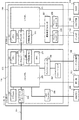
図1は、実施形態に係る画像形成装置100の構成を説明するブロック図である。尚、実施形態では、本発明に係る情報処理装置の一例として画像形成装置100を例に説明する。この画像形成装置100は、原稿の読み取り機能、ファクシミリの送受信機能、印刷機能、ボックス機能などを備えた複合機の例で説明するが、本発明はこのような複合機に限定されず、例えば携帯端末や通信装置、PC等の電子機器であっても良い。
FIG. 1 is a block diagram illustrating a configuration of an
画像形成装置100は、原稿の画像を光学的に読み取ってデジタル画像信号に変換するスキャナ部101、デジタル画像信号に基づいてシートに画像を印刷するプリンタ部102、ユーザとのインターフェースを司る操作部103を有している。更に装置全体を制御するコントローラ(制御部)104、デジタル画像データや制御プログラム等を記憶する大容量の記憶装置(以下、HDD)105、電話回線等にデジタル画像を送信するFAX部106を有している。また、この画像形成装置100は、LAN107経由でコンピュータ(PC)108との間でデジタル画像データの入出力、ジョブの発行や機器の指示等も行なうことが可能である。
The
スキャナ部101は、原稿束を積載し、その原稿束から一枚ずつスキャナユニット122に給紙する原稿給紙ユニット121、原稿を光学スキャンし、その原稿の画像をデジタル画像信号に変換するスキャナユニット122を有している。このスキャナユニット122により生成された画像信号はコントローラ104に送信される。プリンタ部102は、紙束から一枚ずつ逐次給紙可能な給紙ユニット142、給紙された紙に、画像データに基づく画像を印刷するマーキングユニット141、印刷後の紙を排紙するための排紙ユニット143を備えている。
The
またコンピュータ(PC)108は、LAN107を経由で、画像形成装置100に印刷ジョブなどを送信してジョブを実行させる。実施形態では、コンピュータ108は、コントローラ104にOFF指示を出力すると、コントローラ104は画像形成装置100のOFFプロセスを制御する。
Further, the computer (PC) 108 transmits a print job or the like to the
次に、実施形態に係る画像形成装置100が有する機能について説明する。
・複写機能
スキャナ部101で読み込んだ原稿の画像データをHDD105に記録し、同時にプリンタ部102を使用して印刷を行なう。
・画像送信機能
スキャナ部101が原稿を読み取って生成した画像データを、LAN107を介してコンピュータ108に送信する。
・画像保存機能(ボックス機能)
スキャナ部101が原稿を読み取って生成した画像データをHDD105に記録し、必要に応じて送信や印刷を行なう。
・画像印刷機能
コンピュータ108から受信した印刷ジョブに含まれる、例えばページ記述言語を解析し、プリンタ部102で印刷する。
Next, the functions of the
Copy function The image data of the original document read by the
-Image transmission function The image data generated by the
-Image save function (box function)
The
-Image printing function For example, the page description language included in the print job received from the
図2は、実施形態に係る画像形成装置100のコントローラ(制御部)104のハードウェア構成を説明するブロック図である。
FIG. 2 is a block diagram illustrating a hardware configuration of a controller (control unit) 104 of the
コントローラ104は、メインボード200と、サブボード220を含んでいる。メインボード200はいわゆる汎用的なCPUシステムである。ボード全体を制御するメインCPU201、ブートプログラムを記憶しているブートロム202、CPU201がワークメモリとして使用するメモリ203、外部バスとのブリッジ機能を持つバスコントローラ204、及び不揮発性メモリ205を有している。更に、時計機能を有するRTC211、HDD105等のストレージ装置を制御するディスクコントローラ206と、半導体デバイスで構成された比較的小容量な不揮発性記憶装置であるフラッシュディスク(SSD等)207を有している。更に、USBメモリ209を接続するUSBコントローラ208等を有している。このメインボード200には、USBメモリ209、操作部103、HDD105等が接続される。またメインCPU201は、ストレージとしてHDD105を接続しているか、或いは他の種類のストレージを接続しているかは、それを接続しているコントローラに応じて判別できるものとする。ネットワークインタフェース210は、LAN107に接続して、ネットワークを介したデータの送受信を行う。
The
サブボード220は、比較的小さな汎用サブCPUシステムと、画像処理ハードウェアを有している。ボード全体を制御するサブCPU221、CPU221がワークメモリとして使用するメモリ223を有している。更に、外部バスとのブリッジ機能を持つバスコントローラ224、不揮発性メモリ225、リアルタイムでデジタル画像処理を行なう画像処理プロセッサ227と、エンジンコントローラ226を有する。スキャナ部101とプリンタ部102は、エンジンコントローラ226を介してデジタル画像データの受け渡しを行なう。またFAX部106は、サブCPU221が直接制御する。尚、このブロック図は、簡略化して示している。例えばメインCPU201、サブCPU221等にはチップセット、バスブリッジ、クロックジェネレータ等のCPU周辺ハードウェアが多数含まれている。しかしながら、これらは本発明の説明には不要であるため省略しており、このブロック構成が本発明を制限するものではない。
The
次に、実施形態に係るコントローラ104の動作について、紙への複写を例に説明する。
Next, the operation of the
利用者が操作部103から複写を指示すると、メインCPU201がサブCPU221を介してスキャナ部101に原稿の読み取り命令を送る。スキャナ部101は、原稿を光学スキャンしてデジタル画像データに変換して、その画像データをエンジンコントローラ226を介して画像処理プロセッサ227に入力する。画像処理プロセッサ227は、サブCPU221を介して、DMA転送でデジタル画像データをメモリ223に一時保存する。
When the user instructs the
メインCPU201は、デジタル画像データがメモリ223に一定量、或いは全て記憶されたことを確認すると、サブCPU221を介してプリンタ部102に画像出力指示を出す。これによりサブCPU221は、画像処理プロセッサ227にメモリ223の画像データのアドレスを通知する。画像処理プロセッサ227は、プリンタ部102からの同期信号に従って、メモリ223の画像データを、画像処理プロセッサ227とエンジンコントローラ226を介してプリンタ部102に出力する。こうしてプリンタ部102により、紙(シート)にデジタル画像データに基づく画像が印刷される。
When the
複数部の印刷を行なう場合、メインCPU201がメモリ223の画像データをHDD105に保存する。これにより2部目以降は、スキャナ部101から画像データを受け取ることなく、プリンタ部102により画像を印刷することができる。
When printing a plurality of copies, the
図3は、実施形態に係る画像形成装置100における電源の供給と電力モードを説明するブロック図である。図3では、前述の画像形成装置100のブロック図で示す部分の内、本実施形態に係る部分のみを説明する。ここでは本発明の説明に必要最低限の部分だけを説明するため、本発明を実施する際にその形には限定されない。
FIG. 3 is a block diagram illustrating a power supply and a power mode in the
ここではメインCPU201、データを格納するHDD105、メインCPU201とHDD105の間にインターフェイスとして動作するディスクコントローラ206を例に挙げている。電源300は、装置へ電力を供給している。常時監視部301は、スタンバイモード、或いはスリープモードに拘らず動作している。
Here, the
常時監視部301は、メインCPU201から指示を受けて、電源300の制御を行う。またスリープモード中、LAN107や操作部103を監視し、スリープモードからの復帰条件が揃うと(例えば操作部103のボタン押下、或いはLAN107経由でPCから通知が来る)電源300へ指示して、システムを復帰させる。
The
次に、スタンバイモード時とスリープモード時の通電部に関して説明する。 Next, the energized unit in the standby mode and the sleep mode will be described.
図3(A)はスタンバイモードの状態を示し、このときは全てのデバイスに電源が供給されている。 FIG. 3A shows a state of standby mode, in which power is supplied to all devices at this time.
図3(B)はスリープモードの状態を示し、メインCPU201、ディスクコントローラ206、HDD105への電源供給が停止している。
FIG. 3B shows the sleep mode, and the power supply to the
このような構成で、スタンバイモードからスリープモードへ移行するとき、またスリープモードからスタンバイモードへ復帰するときに、HDD105にはオフ/オンが発生する。
With such a configuration, the
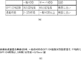
図4は、ストレージの種類に対応したスリープ時間間隔の一例を説明する図である。 FIG. 4 is a diagram illustrating an example of a sleep time interval corresponding to a storage type.
図4(A)に示すように、一般的なHDDのオフ/オン回数は30万回程度である。これに対してサーバ用のHDDのオフ/オン回数は60万回程度である。更にSSDのオフ/オン回数は、無限に近い値である。 As shown in FIG. 4A, a general HDD is turned off / on about 300,000 times. On the other hand, the number of times the HDD for the server is turned off / on is about 600,000 times. Further, the SSD off / on count is a value close to infinity.
いま画像形成装置の設計寿命が5年とすると、その画像形成装置の寿命の5年以内にHDDが故障すると、サービスマンによるHDD交換が発生するため、ユーザが一時的に画像形成装置を利用できなくなるおそれがある。 Assuming that the design life of the image forming apparatus is 5 years, if the HDD fails within 5 years of the life of the image forming apparatus, the HDD is replaced by a serviceman, so that the user can temporarily use the image forming apparatus. It may disappear.
図4(B)では、画像形成装置の設計寿命を5年としたとき、その5年の間に、HDDのオフ/オンの回数が30万回発生することを前提に計算すると、そのオフ/オンの時間間隔は最低でも8.76分となる。従って、典型的な例では、このオフ/オンの時間間隔を10分としている。 In FIG. 4B, assuming that the design life of the image forming apparatus is 5 years, the number of times the HDD is turned off / on occurs 300,000 times during the 5 years. The on time interval is at least 8.76 minutes. Therefore, in a typical example, this off / on time interval is set to 10 minutes.
しかし、このようにオフ/オンの時間間隔を設定すると、スリープモードに移行する条件が満足されても、前回、HDDがオフ/オンしたか時間から所定時間(10分)が経過していないと、スリープモードに移行できない事態が発生する。このようにスリープモードに移行できない事態が発生すると、無駄に電力を消費する時間が長くなり、消費電力を低減させることができなくなるという問題がある。 However, if the off / on time interval is set in this way, even if the condition for shifting to the sleep mode is satisfied, if the predetermined time (10 minutes) has not passed from the time when the HDD was turned off / on last time. , A situation occurs in which the sleep mode cannot be entered. When such a situation in which the sleep mode cannot be entered occurs, there is a problem that the time for wasting power consumption becomes long and the power consumption cannot be reduced.
図5は、実施形態に係る画像形成装置がスリープモード(省電力モード)に移行するときの処理を説明するフローチャートである。ここでは、オフ/オンの時間間隔として、少なくとも10分を確保する例で説明する。 FIG. 5 is a flowchart illustrating a process when the image forming apparatus according to the embodiment shifts to the sleep mode (power saving mode). Here, an example of securing at least 10 minutes as the off / on time interval will be described.
処理が開始されるとまずS501で画像形成装置はスタンバイ状態で、スリープ状態に移行できるかどうか、即ち、スリープ可能回数(カウンタのカウント値)が「0」よりも大きいかどうか判定する。ここでスリープ可能回数が「0」よりも大きいと判定するとS504に進むが、そうでないときはS502に進む。S502で画像形成装置は、スタンバイ状態であって、且つ連続してスタンバイ状態である状態が所定時間(ここでは上述の10分)が経過したかどうか判定する。そして10分が経過したと判定するとS503に進んで、上述のスリープ可能回数を+1(カウントアップ)してS501に進む。一方、S502で0分が経過していないと判定するとS501に進む。 When the processing is started, first, in S501, the image forming apparatus is in the standby state, and it is determined whether or not the sleep state can be entered, that is, whether or not the number of sleepable times (count value of the counter) is larger than "0". Here, if it is determined that the number of sleepable times is larger than "0", the process proceeds to S504, but if not, the process proceeds to S502. In S502, the image forming apparatus determines whether or not a predetermined time (here, the above-mentioned 10 minutes) has elapsed in the standby state and the continuous standby state. Then, when it is determined that 10 minutes have passed, the process proceeds to S503, the number of sleepable times described above is increased by +1 (count up), and the process proceeds to S501. On the other hand, if it is determined in S502 that 0 minutes have not passed, the process proceeds to S501.
S504で画像形成装置は、例えば所定の時間ジョブが投入されないか、或いはユーザが操作しない等により、スリープモードに移行できる条件を満足したかどうか判定する。ここでスリープモードに移行できる条件を満足したと判定するとS505に進み、そうでないときはS502に進む。S505で画像形成装置は、スリープ可能回数を−1(カウントダウン)して、スリープモードへ移行する。尚、このカウンタは、不揮発メモリ205或いはHDD105に格納されている。
In S504, the image forming apparatus determines whether or not the condition for shifting to the sleep mode is satisfied because, for example, the job is not input for a predetermined time or the user does not operate the job. If it is determined that the condition for shifting to the sleep mode is satisfied, the process proceeds to S505, and if not, the process proceeds to S502. In S505, the image forming apparatus counts down the number of sleepable times to -1 (countdown) and shifts to the sleep mode. This counter is stored in the
このようにして画像形成装置がスタンバイ状態の時に、上述のオフ/オンの時間間隔が10分以上となった回数をスリープ可能回数として記憶しておく。これにより、画像形成装置の設計寿命の間に、HDDのオフ/オンの時間間隔の平均が所定時間(ここでは10分)を下回らないように制御することができる。 In this way, when the image forming apparatus is in the standby state, the number of times the above-mentioned off / on time interval is 10 minutes or more is stored as the number of sleepable times. Thereby, during the design life of the image forming apparatus, it is possible to control so that the average of the time intervals of the HDD off / on does not fall below a predetermined time (here, 10 minutes).
図6は、故障したHDDを取り換える例を説明する図である。 FIG. 6 is a diagram illustrating an example of replacing a failed HDD.
前述した通り、昨今、ストレージがHDDからSSDへシフトするなかで、画像形成装置のHDDが故障した場合、同じ種類のHDDを確保することができなくなる場合も出てくる。従って、故障したHDDを取り換える例として、以下の3つのケースが考えられる。 As described above, in recent years, as the storage shifts from HDD to SSD, if the HDD of the image forming apparatus fails, it may not be possible to secure the same type of HDD. Therefore, the following three cases can be considered as examples of replacing a failed HDD.
図6(A)は、HDDからSSDへ完全移行した場合、HDDが故障するとSSDが換装された場合を示す。 FIG. 6A shows a case where the SSD is replaced when the HDD fails when the HDD is completely migrated to the SSD.
図6(B)は、同一種類のHDDが確保できない場合を示し、HDDが故障すると別の種類のHDDが換装された場合を示す。 FIG. 6B shows a case where the same type of HDD cannot be secured, and shows a case where another type of HDD is replaced when the HDD fails.
図6(C)は、コスト削減のため、HDDが故障したときに、リサイクルHDD(一定寿命が消費したHDD)が換装された場合を示す。 FIG. 6C shows a case where a recycled HDD (HDD having a certain life) is replaced when the HDD fails in order to reduce costs.
図6(A)の場合、SSDは構造上、オフ/オン回数の制限がないため、オフ/オンの時間間隔を考慮する必要がない。従って、SSDに交換されたにも拘らず、従前と同様のオフ/オンの回数制御を行うと、無駄な消費電力が発生することになる。 In the case of FIG. 6A, since the SSD has no limit on the number of times of off / on due to its structure, it is not necessary to consider the time interval of off / on. Therefore, even though the SSD has been replaced, if the same off / on count control as before is performed, wasteful power consumption will occur.
図6(B)(C)の場合、元のHDDより寿命の長いHDDが搭載された場合は、必要以上にオフ/オンの時間間隔が長くなり、無駄な消費電力が発生することになる。また元のHDDより寿命の短いHDDが搭載された場合は、そのHDDは、装置の製品寿命に達する前に、その寿命が尽きるおそれがある。 In the case of FIGS. 6B and 6C, when an HDD having a longer life than the original HDD is mounted, the off / on time interval becomes longer than necessary, resulting in wasteful power consumption. Further, when an HDD having a shorter life than the original HDD is mounted, the life of the HDD may expire before the product life of the device is reached.
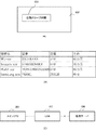
図7(A)は、実施形態に係る画像形成装置100においてHDD105のオフ/オン時間を制御する構成を説明するブロック図である。
FIG. 7A is a block diagram illustrating a configuration for controlling the off / on time of the
メインCPU201は、この画像形成装置100の初回起動の日付を不揮発メモリ205に記録する。従って、それ以降は、初回起動時の日時と、現在の日時とを比較して、その画像形成装置100の残り寿命を算出する。
The
メインCPU201は、ディスクコントローラ206を通じてHDD105へ問い合わせて(一般的にSATAコマンドを用いる)、HDD105のSMART情報(HDDの内蔵情報)から、そのHDDで既に実行されたオフ/オンの回数を取得する。
The
またメインCPU201は、SATAコマンドでHDD105から取得した型番を用いて、例えばLAN107経由でサーバ700へ問い合わせて、そのHDD105の最大オフ/オン回数を取得する。
Further, the
そしてメインCPU201は、その情報からHDD105の残り寿命を算出する。そしてメインCPU201は、HそのDD105の残りのオフ/オン回数と、画像形成装置100の残り寿命から、これからのHDD105のオフ/オンの時間間隔を算出し、その時間間隔を常時監視部301に設定する。そして常時監視部301は、その設定された時間間隔に応じて電源300を制御し、HDD105のオフ/オンを制御する。
Then, the
図7(B)は、実施形態に係る画像形成装置100がHDDのオフ/オンの時間間隔を取得して設定する処理を説明するフローチャートである。尚、このフローチャートで示す処理は、メインCPU201がメモリ203に展開したプログラムを実行することにより達成される。
FIG. 7B is a flowchart illustrating a process in which the
この処理は、画像形成装置100の電源がオンされることにより開始される。まずS701でメインCPU201は、画像形成装置100の不揮発メモリ205に記憶されている初回起動の日時と、RTC211により計時されている現在の日時、及び画像形成装置100の寿命とを用いて、画像形成装置100の残り寿命を取得する。次にS702に進みメインCPU201は、HDD105のSMART情報から、HDD105で既に実行されたオフ/オンの回数と、HDD105の最大のオフ/オン回数から残り寿命(残りのオフ/オン回数)を取得する。次にS703に進みメインCPU201は、画像形成装置100の残り寿命と、HDD105の残りのオフ/オン回数から、HDD105のオフ/オン時間間隔を算出して、それを常時監視部301に設定する。
This process is started by turning on the power of the
こうして設定した時間間隔は、図5のS503で所定時間が経過したかどうかを判定するときの、所定時間として使用される。 The time interval set in this way is used as a predetermined time when determining whether or not a predetermined time has elapsed in S503 of FIG.
尚、この実施形態では、画像形成装置100の電源がオンされることにより図7(B)の処理を開始しているが、本発明はこれに限定されない。
In this embodiment, the process of FIG. 7B is started by turning on the power of the
以下例を使って説明する
(A)例1:設計寿命が5年の画像形成装置を2年間使用した後、新品のHDD(オフ/オン可能回数が50万回)に換装した場合は下記となる。この場合は、設計寿命が5年から使用済の2年を差し引いた差分値を、オフ/オン可能回数(50万回)で除算することにより求められる。
The following will be described using an example (A) Example 1: When the image forming apparatus having a design life of 5 years is used for 2 years and then replaced with a new HDD (the number of times that it can be turned off / on is 500,000 times) is as follows. Become. In this case, it is obtained by dividing the difference value obtained by subtracting the used 2 years from the design life of 5 years by the number of times that the design life can be turned off / on (500,000 times).
(5−2)年/50万回=3.15(分/回)
この場合は、HDDのオフ/オンの時間間隔を、最小4分となるように制御プログラムに対して設定する。
(B)例2:設計寿命が5年の画像形成装置を2年間使用した後、中古のHDD(残りのオフ/オン可能回数が10万回)に換装した場合は下記となる。
(5-2) Year / 500,000 times = 3.15 (minutes / time)
In this case, the HDD off / on time interval is set for the control program so as to be a minimum of 4 minutes.
(B) Example 2: When the image forming apparatus having a design life of 5 years is used for 2 years and then replaced with a used HDD (the remaining number of times that the image can be turned off / on is 100,000 times) is as follows.
(5−2)年/10万回=15.77(分/回)
この場合は、HDDのオフ/オンの時間間隔を、最小16分となるように制御プログラムに対して設定する。
(C)例3:HDDからSSDに換装した場合、オフ/オンの時間間隔を0分となるように制御プログラムに対して設定する。
(5-2) Year / 100,000 times = 15.77 (minutes / time)
In this case, the HDD off / on time interval is set for the control program so as to be a minimum of 16 minutes.
(C) Example 3: When the HDD is replaced with the SSD, the off / on time interval is set to 0 minutes for the control program.
実施形態によれば、動的にオフ/オンの時間間隔を制御プログラムに設定することによって、寿命の長いストレージに換装した場合は、ストレージのオフ/オンの時間間隔を短くできるため、消費電力の低減を実現できる。 According to the embodiment, by dynamically setting the off / on time interval in the control program, when the storage is replaced with a storage having a long life, the time interval of the storage off / on can be shortened, so that the power consumption can be reduced. Reduction can be realized.
また残り寿命の短いストレージに換装した場合は、そのストレージのオフ/オンの時間間隔を長くすることにより、ストレージを保護することができる。 Further, when the storage is replaced with a storage having a short remaining life, the storage can be protected by lengthening the off / on time interval of the storage.
図8(A)は、実施形態に係る画像形成装置100の操作部103の表示部802に表示された自動スリープ時間を設定するボタン801の一例を示す図である。
FIG. 8A is a diagram showing an example of a
ユーザは、このボタン801を押下することにより、数分〜数時間の単位で、画像形成装置100がスリープモードに移行できる条件を満足した状態が継続したときにスリープモードに移行するための経過時間として設定できる。しかしながら、ユーザが設定した時間によっては、ストレージが許容するオフ/オンの時間間隔を下回るおそれがある。
When the user presses this
その際、操作部103の表示部802には、ユーザの設定の通り表示するが、コントローラ104が、ストレージが許容するオフ/オンの時間間隔となるように、画像形成装置100のスリープモードに移行する時間間隔を制御することになる。
At that time, the
図8(B)は、HDDの型番と、その最大寿命を画像形成装置100に格納した寿命テーブルの一例を示す図である。この情報を参照して、HDDの型番に応じたHDDの情報を取得できる。しかし、ここに記憶されていないHDDの型番の場合は、例えば画像形成装置100からサーバ700に問い合わせて、そのHDDの最大寿命を取得する。そして画像形成装置100は、サーバ700から取得したデータに基づいて、ここに格納しているデータを更新したり、或いはデータを追加する。
FIG. 8B is a diagram showing an example of a life table in which the model number of the HDD and its maximum life are stored in the
図8(C)では、メインCPU201は、LAN107を介してサーバ700と接続できない場合、例えば図4に示すような典型的な寿命を使って計算する。一般的に、PC等で使用される安価なHDDの最大オフ/オン回数は、30万回程度である。
In FIG. 8C, when the
尚、HDDのSMART情報は、各メーカに応じてその情報が一定していないが、例えば、Start/Stop Countとして、そのHDDのスピンドルモータが回転/停止した回数を、例えば最大10万回に対してその割合(%)で記憶している。またPower On hours Countとして、そのHDDの電源がオンの積算時間を、例えば最大10時間に対してその割合(%)で記憶しているものがある。 The SMART information of the HDD is not constant depending on each manufacturer, but for example, as Start / Stop Count, the number of times the spindle motor of the HDD has rotated / stopped is, for example, a maximum of 100,000 times. I remember it at that rate (%). Further, as a Power On hours Count, there is one that stores the integrated time when the power of the HDD is turned on, for example, at a ratio (%) to a maximum of 10 hours.
従って、HDDのSMART情報が、これら情報を含んでいれば、これらからHDDの残りの寿命(通電時間、オフ/オン回数)を取得できる。 Therefore, if the SMART information of the HDD includes such information, the remaining life of the HDD (energization time, number of off / on times) can be obtained from these information.
(その他の実施形態)
本発明は、上述の実施形態の1以上の機能を実現するプログラムを、ネットワーク又は記憶媒体を介してシステム又は装置に供給し、そのシステム又は装置のコンピュータにおける1つ以上のプロセッサーがプログラムを読出し実行する処理でも実現可能である。また、1以上の機能を実現する回路(例えば、ASIC)によっても実現可能である。
(Other embodiments)
The present invention supplies a program that realizes one or more functions of the above-described embodiment to a system or device via a network or storage medium, and one or more processors in the computer of the system or device reads and executes the program. It can also be realized by the processing to be performed. It can also be realized by a circuit (for example, ASIC) that realizes one or more functions.
本発明は上記実施形態に制限されるものではなく、本発明の精神及び範囲から離脱することなく、様々な変更及び変形が可能である。従って、本発明の範囲を公にするために、以下の請求項を添付する。 The present invention is not limited to the above embodiments, and various modifications and modifications can be made without departing from the spirit and scope of the present invention. Therefore, in order to publicize the scope of the present invention, the following claims are attached.
100…画像形成装置、101…スキャナ部、102…プリンタ部、103…操作部、104…コントローラ(制御部)、105…大容量記憶装置(HDD)、300…電源、301…常時監視部 100 ... Image forming device, 101 ... Scanner unit, 102 ... Printer unit, 103 ... Operation unit, 104 ... Controller (control unit), 105 ... Large capacity storage device (HDD), 300 ... Power supply, 301 ... Constant monitoring unit
Claims (9)
前記情報処理装置の残り寿命を取得する取得手段と、
搭載されたストレージを判別する判別手段と、
前記判別手段により判別された前記ストレージの残りのオフ/オン可能回数と、前記取得手段により取得した前記情報処理装置の残り寿命とに基づいて、前記ストレージの最小のオフ/オン時間間隔を設定する設定手段と、
を有することを特徴とする情報処理装置。 An information processing device equipped with storage
An acquisition means for acquiring the remaining life of the information processing device, and
A discriminating means for discriminating the installed storage and
The minimum off / on time interval of the storage is set based on the remaining off / on possible number of times of the storage determined by the discriminating means and the remaining life of the information processing apparatus acquired by the acquisition means. Setting means and
An information processing device characterized by having.
現在の日時を計時する計時手段と、を更に有し、
前記取得手段は、前記記憶手段に記憶された前記情報処理装置の初回起動時の日時と、前記計時手段により計時された現在の日時との差分と、前記情報処理装置の設計寿命とに基づいて前記情報処理装置の残り寿命を取得することを特徴とする請求項1に記載の情報処理装置。 A storage means for non-volatilely storing the date and time when the information processing device is first started and the design life of the information processing device.
It also has a timekeeping means to time the current date and time,
The acquisition means is based on the difference between the date and time when the information processing apparatus is first started stored in the storage means, the current date and time measured by the timing means, and the design life of the information processing apparatus. The information processing apparatus according to claim 1, wherein the remaining life of the information processing apparatus is acquired.
前記スタンバイ状態が継続する時間が、前記最小のオフ/オン時間間隔となる度にカウントアップし、前記スリープ状態に移行する度にカウントダウンされるカウンタとを、更に有し、
前記制御手段は、前記スリープ状態に移行する条件に、前記カウンタのカウント値が0よりも大きいことを含むことを特徴とする請求項1に記載の情報処理装置。 A control means that controls the transition from the standby state to the sleep state,
Further, it has a counter that counts up each time the standby state continues at the minimum off / on time interval and counts down each time the sleep state is entered.
The information processing apparatus according to claim 1, wherein the control means includes a condition for shifting to the sleep state, in which the count value of the counter is larger than 0.
ユーザからの指示に応じて、前記スリープ状態に移行する条件として、当該スリープ状態に移行できる条件を満足した状態が継続する時間を設定する設定手段とを、更に有し、
前記制御手段は、前記設定手段により設定された時間、前記スリープ状態に移行できる条件を満足した状態が継続しても、前記ストレージの最小のオフ/オン時間間隔が確保できない場合は、前記スリープ状態に移行しないことを特徴とする請求項1に記載の情報処理装置。 A control means that controls the transition from the standby state to the sleep state,
Further, as a condition for shifting to the sleep state in response to an instruction from the user, there is a setting means for setting a time during which the state satisfying the condition for shifting to the sleep state continues.
The control means is in the sleep state when the minimum off / on time interval of the storage cannot be secured even if the state in which the condition for transitioning to the sleep state is satisfied continues for the time set by the setting means. The information processing apparatus according to claim 1, wherein the information processing apparatus does not shift to.
前記情報処理装置の取得手段が、前記情報処理装置の残り寿命を取得する取得工程と、
前記情報処理装置の判別手段が、搭載されたストレージを判別する判別工程と、
前記情報処理装置の設定手段が、前記判別工程で判別された前記ストレージの残りのオフ/オン可能回数と、前記取得工程により取得した前記情報処理装置の残り寿命とに基づいて、前記ストレージの最小のオフ/オン時間間隔を設定する設定工程と、
を有することを特徴とする制御方法。 It is a control method for information processing equipment equipped with storage.
The acquisition step in which the acquisition means of the information processing device acquires the remaining life of the information processing device,
The discriminating means for discriminating the information processing device includes a discriminating step of discriminating the mounted storage and
The setting means of the information processing apparatus minimizes the storage based on the remaining number of times the storage can be turned off / on determined in the discrimination step and the remaining life of the information processing apparatus acquired in the acquisition step. The setting process for setting the off / on time interval and
A control method characterized by having.
Priority Applications (2)
| Application Number | Priority Date | Filing Date | Title |
|---|---|---|---|
| JP2017120809A JP6979804B2 (en) | 2017-06-20 | 2017-06-20 | Information processing equipment, its control method, and programs |
| US16/010,826 US10802570B2 (en) | 2017-06-20 | 2018-06-18 | Information processing apparatus, method of controlling the same, and storage medium |
Applications Claiming Priority (1)
| Application Number | Priority Date | Filing Date | Title |
|---|---|---|---|
| JP2017120809A JP6979804B2 (en) | 2017-06-20 | 2017-06-20 | Information processing equipment, its control method, and programs |
Publications (3)
| Publication Number | Publication Date |
|---|---|
| JP2019008372A JP2019008372A (en) | 2019-01-17 |
| JP2019008372A5 JP2019008372A5 (en) | 2020-08-13 |
| JP6979804B2 true JP6979804B2 (en) | 2021-12-15 |
Family
ID=64656128
Family Applications (1)
| Application Number | Title | Priority Date | Filing Date |
|---|---|---|---|
| JP2017120809A Active JP6979804B2 (en) | 2017-06-20 | 2017-06-20 | Information processing equipment, its control method, and programs |
Country Status (2)
| Country | Link |
|---|---|
| US (1) | US10802570B2 (en) |
| JP (1) | JP6979804B2 (en) |
Families Citing this family (5)
| Publication number | Priority date | Publication date | Assignee | Title |
|---|---|---|---|---|
| US11169726B2 (en) * | 2018-09-13 | 2021-11-09 | Toshiba Memory Corporation | Pool-level storage management |
| JP6669371B1 (en) | 2019-01-22 | 2020-03-18 | Necプラットフォームズ株式会社 | Electronic equipment cover and electronic equipment |
| JP7189442B2 (en) * | 2019-05-30 | 2022-12-14 | 株式会社バッファロー | ELECTRONIC DEVICE, POWER DETERMINATION METHOD, COMPUTER PROGRAM, AND ELECTRONIC DEVICE SYSTEM |
| JP7396090B2 (en) * | 2020-02-12 | 2023-12-12 | 京セラドキュメントソリューションズ株式会社 | Image processing device |
| KR20230166656A (en) * | 2022-05-31 | 2023-12-07 | 휴렛-팩커드 디벨롭먼트 컴퍼니, 엘.피. | Sleep mode management of hard disk drive |
Family Cites Families (5)
| Publication number | Priority date | Publication date | Assignee | Title |
|---|---|---|---|---|
| JP2005186426A (en) * | 2003-12-25 | 2005-07-14 | Fuji Xerox Co Ltd | Method of controlling image forming apparatus and image forming apparatus |
| US8958993B2 (en) * | 2009-02-23 | 2015-02-17 | Mitsubishi Electric Corporation | Switching-device remaining lifetime diagnosis method and apparatus |
| JP5676902B2 (en) | 2010-03-25 | 2015-02-25 | キヤノン株式会社 | Information processing apparatus and information processing apparatus control method |
| JP5899724B2 (en) * | 2011-09-07 | 2016-04-06 | カシオ電子工業株式会社 | Electronic equipment |
| JP2016103704A (en) * | 2014-11-27 | 2016-06-02 | キヤノン株式会社 | Image forming apparatus, control method of image forming apparatus, and program |
-
2017
- 2017-06-20 JP JP2017120809A patent/JP6979804B2/en active Active
-
2018
- 2018-06-18 US US16/010,826 patent/US10802570B2/en active Active
Also Published As
| Publication number | Publication date |
|---|---|
| JP2019008372A (en) | 2019-01-17 |
| US10802570B2 (en) | 2020-10-13 |
| US20180364793A1 (en) | 2018-12-20 |
Similar Documents
| Publication | Publication Date | Title |
|---|---|---|
| JP6979804B2 (en) | Information processing equipment, its control method, and programs | |
| US9360912B2 (en) | Shutdown processing mode with forcible power off | |
| CN102673125B (en) | Image forming apparatus and method for controlling image forming apparatus | |
| CN103917924B (en) | Image forming apparatus and control method thereof | |
| KR101496537B1 (en) | Image forming apparatus, method for controlling image forming apparatus, and storage medium | |
| JP6789713B2 (en) | Image forming device and control method | |
| US8977872B2 (en) | Information processing apparatus having power saving mode, and control method and storage medium therefor | |
| US20140160507A1 (en) | Image processing apparatus, method for controlling image processing apparatus, and program | |
| US9423857B2 (en) | Apparatus and method for extending life of a storage unit by delaying transitioning to a hibernation state for a predetermined time calculated based on a number of writing times of the storage unit | |
| JP6489751B2 (en) | Data processing apparatus, control method therefor, and program | |
| KR101596095B1 (en) | Printing apparatus and recording medium | |
| US10455103B2 (en) | Power control method of printing apparatus | |
| JP2013041458A (en) | Data processing apparatus and control method therefor | |
| US20140340703A1 (en) | Image processing apparatus, method of controlling image processing apparatus, and program | |
| US20130191623A1 (en) | Information processing apparatus, control method therefor, and storage medium | |
| US11330132B2 (en) | Information processing apparatus capable of resetting system, method of controlling same, and storage medium | |
| JP2016197324A (en) | Information processing device, control method for information processing device, and program | |
| JP6459543B2 (en) | Image forming apparatus, job processing control method, and job processing control program | |
| JP2018157603A (en) | Image forming apparatus, control method for image forming apparatus, and computer program | |
| JP5800861B2 (en) | Information processing apparatus, control method for information processing apparatus, and control program | |
| US11249653B2 (en) | Apparatus and method for storing image data in a storage based on information regarding a number of writes | |
| JP5808136B2 (en) | Image forming apparatus, control method thereof, and program | |
| JP2012050040A (en) | Image forming device and facsimile program |
Legal Events
| Date | Code | Title | Description |
|---|---|---|---|
| A521 | Written amendment |
Free format text: JAPANESE INTERMEDIATE CODE: A523 Effective date: 20200618 |
|
| A621 | Written request for application examination |
Free format text: JAPANESE INTERMEDIATE CODE: A621 Effective date: 20200618 |
|
| RD01 | Notification of change of attorney |
Free format text: JAPANESE INTERMEDIATE CODE: A7421 Effective date: 20210103 |
|
| A521 | Written amendment |
Free format text: JAPANESE INTERMEDIATE CODE: A523 Effective date: 20210113 |
|
| A977 | Report on retrieval |
Free format text: JAPANESE INTERMEDIATE CODE: A971007 Effective date: 20210331 |
|
| A131 | Notification of reasons for refusal |
Free format text: JAPANESE INTERMEDIATE CODE: A131 Effective date: 20210405 |
|
| A521 | Written amendment |
Free format text: JAPANESE INTERMEDIATE CODE: A523 Effective date: 20210602 |
|
| TRDD | Decision of grant or rejection written | ||
| A01 | Written decision to grant a patent or to grant a registration (utility model) |
Free format text: JAPANESE INTERMEDIATE CODE: A01 Effective date: 20211018 |
|
| A61 | First payment of annual fees (during grant procedure) |
Free format text: JAPANESE INTERMEDIATE CODE: A61 Effective date: 20211116 |
|
| R151 | Written notification of patent or utility model registration |
Ref document number: 6979804 Country of ref document: JP Free format text: JAPANESE INTERMEDIATE CODE: R151 |