JP6234425B2 - Electrocardiograph electrode unit, electrode pad and electric cable - Google Patents
Electrocardiograph electrode unit, electrode pad and electric cable Download PDFInfo
- Publication number
- JP6234425B2 JP6234425B2 JP2015249853A JP2015249853A JP6234425B2 JP 6234425 B2 JP6234425 B2 JP 6234425B2 JP 2015249853 A JP2015249853 A JP 2015249853A JP 2015249853 A JP2015249853 A JP 2015249853A JP 6234425 B2 JP6234425 B2 JP 6234425B2
- Authority
- JP
- Japan
- Prior art keywords
- electrode
- electrocardiogram
- connector
- terminal
- electric cable
- Prior art date
- Legal status (The legal status is an assumption and is not a legal conclusion. Google has not performed a legal analysis and makes no representation as to the accuracy of the status listed.)
- Active
Links
Images


Landscapes
- Measurement And Recording Of Electrical Phenomena And Electrical Characteristics Of The Living Body (AREA)
Description
本発明は、双極誘導を用いる心電図モニターに接続して心電を測定するための電極パッドと電気ケーブルとからなる心電測定用電極ユニットに関する。 The present invention relates to an electrode unit for measuring an electrocardiogram comprising an electrode pad and an electric cable for measuring an electrocardiogram by connecting to an electrocardiogram monitor using bipolar induction.
従来、双極誘電を用いる心電図を得るためには、アイントーベンの三角形の原理に基づき、右肩近傍にマイナス電極を貼り付け、左脇腹にプラス電極を貼り付け、左方近傍にアース電極を貼り付けることが一般的である。しかし、体の3箇所に電極を取り付けるのは煩雑であり、緊急の場合などには服を脱がせたり、場合によっては服を切ったりする必要がある。また、いずれかの電極が外れた場合、3つの電極のうちのどれが外れたのかを即座に特定することが難しい。
これに対して、下記特許文献には単極誘導を用いる心電図モニター用の電極パッドが開示されている。この電極パッドは1枚のシートにプラス電極とアース電極が設けられており胸骨近傍に貼り付けると心電図を得ることができる。当該先行技術文献には電極を3以上にしてもよいことが記載され、また、胸骨近傍の3箇所に電極を接触させても双極誘電を用いる心電図を得ることができるので、一枚のシートに3つの電極を設けた電極パッドを用いれば双極誘電を用いる場合にも用いることができると考えられる。そして、このような構成によれば、一回の動作で貼り付けることができ、また、服を脱がさなくても、服の上又は下から挿入して張り付けることができ、さらに、電極が外れた際に、場所の特定に困らないようにすることが可能である。また、胸骨上には筋肉がないので、筋電による影響を最小限にすることもできる。
Conventionally, in order to obtain an electrocardiogram using bipolar dielectric, based on the principle of Einthoven's triangle, a negative electrode is attached near the right shoulder, a positive electrode is attached on the left flank, and an earth electrode is attached near the left side. It is common. However, it is cumbersome to attach electrodes to three parts of the body, and it is necessary to take off clothes or to cut clothes depending on circumstances. In addition, when any one of the electrodes is detached, it is difficult to immediately identify which of the three electrodes is detached.
In contrast, the following patent document discloses an electrode pad for an electrocardiogram monitor using unipolar induction. This electrode pad is provided with a plus electrode and a ground electrode on a single sheet, and an electrocardiogram can be obtained when it is attached near the sternum. The prior art document describes that the number of electrodes may be three or more, and an electrocardiogram using bipolar dielectric can be obtained even if the electrodes are brought into contact with three locations near the sternum. If an electrode pad provided with three electrodes is used, it can be considered that it can also be used when bipolar dielectric is used. According to such a configuration, it can be pasted with a single operation, and can be inserted and pasted from above or below the clothes without taking off the clothes. In this case, it is possible not to be troubled by specifying the location. In addition, since there is no muscle on the sternum, the influence of myoelectricity can be minimized.
ところで、上記のように一枚のシートに電極をまとめると、電極間の電位差が小さくなってしまうために、心電図の波形が小さくなるという問題が生じる。従来のように電極が分離していると電極の取り付けを変えることで対応できるが、一枚のシートに電極が固定されているとこのような対処をすることはできない。また、心電図モニターの波形を画面上で増幅することもできるが、この場合、ノイズとなる筋電図も増幅されてしまうという問題が生じる。
本発明はこのような問題に鑑みて、双極誘電を用いた心電図モニターに用いられる電極を一つのシート等にまとめる場合において、心電図の波形をより明瞭にし、かつ、筋電図の混入を低減させることを課題とする。
By the way, when the electrodes are combined into one sheet as described above, the potential difference between the electrodes becomes small, which causes a problem that the waveform of the electrocardiogram becomes small. If the electrodes are separated as in the prior art, it can be dealt with by changing the attachment of the electrodes, but if the electrodes are fixed to one sheet, such a countermeasure cannot be taken. Further, the waveform of the electrocardiogram monitor can be amplified on the screen, but in this case, there is a problem that the electromyogram that becomes noise is also amplified.
In view of such problems, the present invention makes the waveform of an electrocardiogram clearer and reduces the mixture of electromyograms when the electrodes used in an electrocardiogram monitor using bipolar dielectric are combined on a single sheet or the like. This is the issue.
請求項4に記載の発明は、請求項2に記載の心電測定用電極ユニットにおいて、前記電気ケーブルを構成する3本の電線は、前記心電図モニター近傍から前記コネクター近傍において一本にまとめられ、端部で3本に分かれるように形成されるものである。According to a fourth aspect of the present invention, in the electrode unit for electrocardiogram measurement according to the second aspect, the three electric wires constituting the electric cable are grouped together from the vicinity of the electrocardiogram monitor to the vicinity of the connector, It is formed to be divided into three at the end.
請求項5に記載の発明は、請求項4に記載の心電測定用電極ユニットにおいて、前記端子は三角形状に配置されるとともに、前記各端子には先端が基端に対して当該三角形の最も近い角の方向を向くような導電性のフックが形成され、前記コネクターは前記フックに掛る前記電気ケーブルに接続される導電性のリング又はフックから形成され、前記端子の導電性フックに掛った状態において弾性体によって掛りがはずれない方向に付勢されるものである。 According to a fifth aspect of the present invention, in the electrode unit for electrocardiogram measurement according to the fourth aspect, the terminals are arranged in a triangular shape, and the distal end of each terminal is the most of the triangular shape with respect to the base end. A conductive hook is formed so as to face the direction of a near corner, and the connector is formed of a conductive ring or hook connected to the electric cable that is hooked on the hook, and is hooked on the conductive hook of the terminal In this case, the elastic member is urged in a direction not to be detached.
請求項6に記載の発明は、請求項4又は5に記載の心電測定用電極ユニットにおいて、前記電気ケーブルの前記コネクタ側の端部で3本に分かれる接合位置近傍に人体表面に吸着可能な吸盤が設けられるものである。 According to a sixth aspect of the present invention, in the electrode unit for electrocardiographic measurement according to the fourth or fifth aspect, the human body surface can be adsorbed in the vicinity of a joint position divided into three at the connector-side end of the electric cable. A suction cup is provided.
請求項7に記載の発明は、前記心電測定用電極ユニットにおいて、前記各電極は正三角形の頂点を形成する位置に配置されるものである。 According to a seventh aspect of the present invention, in the electrocardiographic measurement electrode unit, each of the electrodes is arranged at a position forming an apex of an equilateral triangle.
請求項8に記載の発明は、請求項2から7のいずれかに記載の心電測定用電極ユニットにおいて、前記電極ユニットは、前記プラス電極から当該プラスに接続された端子に至るまでの電気抵抗値が前記マイナス電極から当該マイナス電極に接続された端子に至るまでの電気抵抗値よりも小さくなるように形成されるものである。 The invention according to claim 8 is the electrocardiographic electrode unit according to any one of claims 2 to 7, wherein the electrode unit has an electrical resistance from the plus electrode to the terminal connected to the plus. The value is formed so as to be smaller than an electric resistance value from the minus electrode to a terminal connected to the minus electrode.
請求項9に記載の発明は、請求項2、4、5、6のいずれかに記載の心電測定用電極ユニットにおいて、前記電気ケーブルは、前記プラス電極に接続された端子に接続可能なコネクター部分とこれに接続される電線までの電気抵抗値が、前記マイナス極に接続された端子に接続可能なコネクター部分とこれに接続される電線までの電気抵抗値よりも小さくなるように形成されるものである。 The invention according to claim 9 is the electrode unit for electrocardiogram measurement according to any one of claims 2, 4, 5, and 6, wherein the electrical cable is a connector connectable to a terminal connected to the plus electrode. The electrical resistance value between the portion and the electric wire connected thereto is formed to be smaller than the electric resistance value between the connector portion connectable to the terminal connected to the negative electrode and the electric wire connected thereto. Is.
請求項10に記載の発明は、請求項8に記載の電極パッドである。 The invention according to
請求項11に記載の発明は、請求項9に記載の電気ケーブルである。 The invention according to
請求項4に記載の発明は、請求項2又は3に記載の心電測定用電極ユニットにおいて、前記プラス電極から当該プラスに接続された端子に至るまでの電気抵抗値が前記マイナス電極から当該マイナス電極に接続された端子に至るまでの電気抵抗値よりも小さくなるように形成されるものである。
請求項5に記載の発明は、請求項2に記載の心電測定用電極ユニットにおいて、前記プラス電極に接続された端子に接続可能なコネクター部分とこれに接続される電線までの電気抵抗値が、前記マイナス極に接続された端子に接続可能なコネクター部分とこれに接続される電線までの電気ケーブルの電気抵抗値よりも小さくなるように形成されるものである。
請求項6に記載の発明は、請求項2、4、5のいずれかに記載の心電測定用電極ユニットにおいて、前記電気ケーブルを構成する3本の電線は、前記心電図モニター近傍から前記コネクター近傍において一本にまとめられ、端部で3本に分かれるように形成されるものである。
請求項7に記載の発明は、請求項6に記載の心電測定用電極ユニットにおいて、前記端子は三角形状に配置されるとともに、前記各端子には先端が基端に対して当該三角形の最も近い角の方向を向くような導電性のフックが形成され、前記コネクターは前記フックに掛る前記電気ケーブルに接続される導電性のリング又はフックから形成され、前記端子の導電性フックに掛った状態において弾性体によって掛りがはずれない方向に付勢されるものである。
請求項8に記載の発明は、前記心電測定用電極ユニットにおいて、前記各電極は正三角形の頂点を形成する位置に配置されるものである。
請求項9に記載の発明は、請求項2、3、4、7のいずれか記載の電極パッドである。
請求項10に記載の発明は、請求項2、4、6、7のいずれかに記載の電気ケーブルである。
請求項11に記載の発明は、請求項6、7に記載の電気ケーブルであって、前記コネクタ側の端部で3本に分かれる接合位置近傍に人体表面に吸着可能な吸盤が設けられるものである。
According to a fourth aspect of the present invention, in the electrode unit for electrocardiogram measurement according to the second or third aspect, an electrical resistance value from the positive electrode to the terminal connected to the positive is negative from the negative electrode. It is formed so as to be smaller than the electric resistance value up to the terminal connected to the electrode.
According to a fifth aspect of the present invention, in the electrode unit for electrocardiogram measurement according to the second aspect, an electrical resistance value between a connector portion connectable to a terminal connected to the plus electrode and an electric wire connected thereto is provided. The connector portion connectable to the terminal connected to the negative electrode and the electric resistance value of the electric cable up to the electric wire connected thereto are formed to be smaller.
According to a sixth aspect of the present invention, in the electrode unit for electrocardiogram measurement according to any of the second, fourth, and fifth aspects, the three electric wires constituting the electric cable are disposed in the vicinity of the connector from the vicinity of the electrocardiogram monitor. Are formed in one piece and divided into three pieces at the end.
According to a seventh aspect of the present invention, in the electrode unit for electrocardiogram measurement according to the sixth aspect, the terminals are arranged in a triangular shape, and the distal end of each terminal is the most of the triangular shape with respect to the base end. A conductive hook is formed so as to face the direction of a near corner, and the connector is formed of a conductive ring or hook connected to the electric cable that is hooked on the hook, and is hooked on the conductive hook of the terminal In this case, the elastic member is urged in a direction not to be detached.
According to an eighth aspect of the present invention, in the electrode unit for electrocardiogram measurement, each of the electrodes is arranged at a position forming an apex of an equilateral triangle.
The invention according to claim 9 is the electrode pad according to any one of claims 2, 3, 4, and 7.
The invention described in
An eleventh aspect of the invention is the electric cable according to the sixth or seventh aspect, wherein a suction cup that can be adsorbed on the surface of the human body is provided in the vicinity of the joining position divided into three at the end on the connector side. is there.
請求項4に記載の発明は、3本の電線を有する電気ケーブルの途中を一本にまとめることで取り回しや収納をより簡易にすることができる。The invention according to claim 4 can simplify handling and storing by combining the middle portions of the electric cable having three electric wires into one.
請求項5に記載の発明は、簡易な構造で、電極パッドの端子と、電気ケーブルとのコネクタを着脱可能とすることができる。 According to the fifth aspect of the present invention, the connector of the electrode pad terminal and the electric cable can be attached and detached with a simple structure.
請求項6に記載の発明は、コネクターの中心に吸盤が設けられることで、吸盤を人体表面に吸着させ、直接コネクターを皮膚に接触させて心電図を見ることで、電極パッドを貼り付ける前に、貼り付け位置が適切かどうかを判断することができる。 The invention according to claim 6 is that a suction cup is provided at the center of the connector so that the suction cup is adsorbed to the surface of the human body, the connector is directly brought into contact with the skin, and an electrocardiogram is observed. It is possible to determine whether the pasting position is appropriate.
請求項7に記載の発明は、各電極を正三角形状に配置することで、心電図に適切な波形が出ない場合に、120度回転させることで適切な波形を得ることができる。 According to the seventh aspect of the invention, by arranging each electrode in an equilateral triangle shape, an appropriate waveform can be obtained by rotating 120 degrees when an appropriate waveform does not appear in the electrocardiogram.
請求項8に記載の発明は、電極パッドにおいてプラス電極部分とマイナス電極部分との間に抵抗値差を設けておくことで、電気ケーブルや無線装置は抵抗差を設けない一般的に用いられているものを採用することができる。 The invention according to claim 8 is generally used in that an electric cable or a wireless device does not provide a resistance difference by providing a resistance value difference between the plus electrode portion and the minus electrode portion in the electrode pad. You can adopt what you have.
請求項9に記載の発明は、電気ケーブルの電線部分同士において抵抗値差を設けることで、電極パッドは抵抗値差を設ける必要が無くなり、電極パッドの低コスト化に資することができる。 According to the ninth aspect of the invention, by providing a resistance value difference between the electric wire portions of the electric cable, it is not necessary to provide the resistance value difference between the electrode pads, which can contribute to cost reduction of the electrode pad.
請求項10に記載の発明は、適当な電気ケーブル又は無線装置と組み合わせることで、上記効果を奏する心電測定用電極ユニットを得ることができる。 According to the tenth aspect of the present invention, an electrocardiographic measurement electrode unit having the above effects can be obtained by combining with an appropriate electric cable or radio apparatus.
請求項11に記載の発明は、適当な電極パッドと組み合わせることで、上記効果を奏する心電測定用電極ユニットを得ることができる。 According to the eleventh aspect of the present invention, an electrocardiographic electrode unit having the above effects can be obtained by combining with an appropriate electrode pad.
請求項4に記載の発明は、電極パッドにおいてプラス電極部分とマイナス電極部分との間に抵抗値差を設けておくことで、電気ケーブルや無線装置は抵抗差を設けない一般的に用いられているものを採用することができる。
請求項5に記載の発明は、電気ケーブルの電線部分同士において抵抗値差を設けることで、電極パッドは抵抗値差を設ける必要が無くなり、電極パッドの低コスト化に資することができる。
請求項6に記載の発明は、3本の電線を有する電気ケーブルの途中を一本にまとめることで取り回しや収納をより簡易にすることができる。
請求項7に記載の発明は、簡易な構造で、電極パッドの端子と、電気ケーブルとのコネクタを着脱可能とすることができる。
請求項8に記載の発明は、各電極を正三角形状に配置することで、心電図に適切な波形が出ない場合に、120度回転させることで適切な波形を得ることができる。
請求項9に記載の発明は、適当な電気ケーブル又は無線装置と組み合わせることで、上記効果を奏する心電測定用電極ユニットを得ることができる。
請求項10に記載の発明は、適当な電極パッドと組み合わせることで、上記効果を奏する心電測定用電極ユニットを得ることができる。
請求項11に記載の発明は、コネクターの中心に吸盤が設けられることで、吸盤を人体表面に吸着させ、直接コネクターを皮膚に接触させて心電図を見ることで、電極パッドを貼り付ける前に、貼り付け位置が適切かどうかを判断することができる。
The invention according to claim 4 is generally used in that an electric cable and a wireless device do not provide a resistance difference by providing a resistance value difference between the plus electrode portion and the minus electrode portion in the electrode pad. You can adopt what you have.
According to the fifth aspect of the present invention, by providing a resistance value difference between the electric wire portions of the electric cable, the electrode pad need not have a resistance value difference, which can contribute to cost reduction of the electrode pad.
According to the sixth aspect of the present invention, it is possible to simplify the handling and storage by combining the middle portions of the electric cable having three electric wires into one.
According to the seventh aspect of the present invention, the connector between the electrode pad terminal and the electric cable can be attached and detached with a simple structure.
In the invention according to claim 8, by arranging each electrode in an equilateral triangle shape, an appropriate waveform can be obtained by rotating 120 degrees when an appropriate waveform does not appear in the electrocardiogram.
According to the ninth aspect of the present invention, an electrocardiographic measurement electrode unit having the above effects can be obtained by combining with an appropriate electric cable or wireless device.
According to the tenth aspect of the present invention, an electrocardiographic electrode unit having the above effects can be obtained by combining with an appropriate electrode pad.
The invention according to
以下、本発明の実施の形態について、図面を参照しながら説明する。
図1(a)に本実施形態に係る心電測定用電極ユニットXの斜め上方から見た斜視図を示し、(b)に心電測定用電極ユニットXの斜め下方から見た斜視図を示す。心電測定用ユニットXは、電極パッド10と、電気ケーブル20とから構成される。電極パッド10と電気ケーブル20とは後述するコネクター30によって着脱可能に形成されている。
図2(a)に電源パッド10の斜め上方から見た斜視図を示し、(b)に電源パッド10の斜め下方から見た分解斜視図を示す。電極パッド10は、正三角形状のシート11の裏面に3つの円形の電極12a、12b、12cが正三角形の各頂点を構成するように配置され、シート11の表面には各電極12a、12b、12cのそれぞれと上下で電気的に繋がる端子13a、13b、13cが設けられる。そして、シート11の裏面には粘着剤が塗布されるとともに、当該粘着剤を覆うように、当該粘着剤に対して容易に剥離できる剥離紙14が貼り付けられている。端子13a、13b、13cは、下端側が電極12a、12b、12cと一体に連結する円柱体状の脚と、当該脚の上面に固定される円板状の抜け止めとから構成される。当該抜け止めは、各脚が形成する正三角形の重心から離れる方向にずれるように脚の上面に固定されることで、端子13a、13b、13cには、各端子が形成する正三角形のそれぞれ最も近い角の方向を向くようなフックが形成される。
Hereinafter, embodiments of the present invention will be described with reference to the drawings.
FIG. 1A shows a perspective view of the electrocardiogram measurement electrode unit X according to the present embodiment as viewed from diagonally above, and FIG. 1B shows a perspective view of the electrocardiogram measurement electrode unit X as viewed from diagonally below. . The electrocardiogram measurement unit X includes an
FIG. 2A shows a perspective view of the
図3(a)に電気ケーブル20のコネクター30近傍の斜視図を示す。電気ケーブル20は3本の被覆されることで互いに絶縁される電線を束ねたものであり、コネクター30近傍と図示しない心電図モニターへの接続コネクターとの間の中間部分はまとめられてさらに被覆されることで一本のケーブルとなっている。コネクター30は、中央の電気ケーブル20の被覆に固定されるリング34と、リング34に互いに120度の角度をもって同一平面状に広がるよう基端部が固定されるパイプ33a、33b、33c、各パイプ33a、33b、33cの先端に基端が固定される引っ張りバネ32a、32b、32c、各引っ張りバネ32a、32b、32cの先端に外縁が固定される金属製のリング31a、31b、31cとから構成される。リング31aはマイナス極に接続され、31bはアース極に接続され、リング31cはプラス極に接続されることが想定され、これを示すためにリング31aに接続されるパイプ33aは赤色に、リング31bに接続されるパイプ33bは黄色に、リング31cに接続されるパイプ33cは緑色に形成される。リング31a、リング31bとは同じ金属で形成され、リング31cはこれらよりも抵抗が小さい異なる金属で形成されている。電気ケーブルの各電線は先端で3つに分岐してコネクター30の各パイプ33a、33b、33cから引っ張りバネ32a、32b、32cを通って、先端がリング31a、31b、31cに電気的に接続している。図3(b)に一つのパイプ33a、引っ張りバネ32a、リング31a近傍の拡大縦断面図を示す。図に示すように各引っ張りバネ32a、32b、32c内の電線21aは引っ張りバネ32a、32b、32cの伸びに追従できるようにコイル状に巻かれている。また、リング31a、31b、31cは、想像線で示す電極パッド10の端子13a、13b、13cの抜け止めの外径よりやや大きな内径を有するよう形成される。また、コネクター30の中心から各リング31a、31b、31cの内周の最も遠い点までの距離は、電極パッドの重心から各端子13a、13b、13cの脚の外周の最も遠い点までの距離よりも若干短くなるように設定されている。これにより、各リング31a、31b、31cを各端子13a、13b、13cに係合させたときに、引張りバネ32a、32b、32cが若干伸びることとなり、リング31a、31b、311と端子13a、13b、13cの脚との接触が常時維持されることとなる。
FIG. 3A is a perspective view of the vicinity of the
次に、以上のような構成を有する心電測定用電極ユニットXの使用方法について説明する。測定者は、まず電極パッド10の剥離紙を剥がして、電極パッド10裏面の粘着剤部分を図4(a)に示すように被測定者の心臓近傍の胸骨上面の適当な位置に貼り付ける。これにより、各電極12a、12b、12cは被験者の体表面に接触することとなる。なお、図では着衣していないが、着衣状態でも上衣の襟首又は裾から電極パッド10を入れて貼り付けることが可能である。また、電極パッド10の各電極12a、12b、12c、端子13a、13b、13cは同じであるので、図に示すように逆三角形になるように貼り付ければ、どの向きで取り付けてもよい。なお、貼り付けた状態において、右上部分がマイナス極、左上部分がアース極、下部分がプラス極となる。その後、図4(b)に示すように図示しない心電図モニターに接続されている電気ケーブル20のコネクター30を貼り付けた電極パッド10に接続する。コネクター30の接続の方法は、まず、リング31a、31b、31cの内の一つをフックを形成する端子13a、13b、13cの適当なものに引っ掛け、残りのリングは引張りバネを引っ張って、それぞれ端子のフックに引っ掛ける。この際、コネクター30の電気抵抗が最も小さい緑色のパイプ33cに繋がるリング31cが電極パッド10の下に位置する端子に係合するようにする。リング31cが下になると自ずと赤色のパイプ33aに繋がるリング31aは被測定者から見て右上の端子13aに、黄色のパイプ33bに繋がるリング31bは被測定者から見て左上の端子13bに係合することとなる。以上で、心電測定用電極ユニットXの被験者への取り付けが完了し、この状態で心電図モニターで心電図を測定することができる。
以上のような構成を有する心電測定用電極ユニットXを用いると、マイナス電極となるリング31aの抵抗値がプラス電極となるリング31cの抵抗値よりも大きくなっていることで電位差が大きくなり、心電図モニターの心電図の波形を大きくすることができるとともに、筋電図が入りやすいマイナス電極の抵抗が大きいことで、筋電図の混入も低減させることができる。
Next, a method of using the electrocardiographic electrode unit X having the above configuration will be described. The measurer first peels off the release paper of the
When the electrocardiogram measurement electrode unit X having the above-described configuration is used, the potential difference increases because the resistance value of the
なお、上記実施形態では、コネクター30においてプラス電極とマイナス電極との間に抵抗値差を設けたが、電極パッド10における2つの電極及び/又は端子同士の金属を異なる抵抗値のものに変えたり、電気ケーブルにおける2本の電線の抵抗値を変えたりすることでプラス電極とマイナス電極との間に抵抗値差を設けることもできる。
また、上記実施形態では電極パッドは粘着剤によって体に貼り付けるようにしているが、体表面に電極が接触するように固定できれば、種々の手段を採用することができる。例えば、図5(a)に示す電極パッド10Aのように各電極12a、12b、12cを吸盤15a、15b、15cの中央に位置するように設け、当該吸盤15a、15b、15cを体表面に貼り付けることで電極を体表面に接触するようにすることができる。さらに、図5(b)に示すよう電極パッド10Bのように粘着ゲル16a、16b、16cによって電極を体表面に貼り付けることで電極を体表面に接触するようにできる。なお、粘着ゲルは導電性があるので、金属の電極は粘着ゲルの中に位置するようにでき、この場合、粘着ゲル表面が体表面に接触する電極となる。
それから、図6に示すコネクター30Aのように、コネクターの底面に吸盤33を設けるようにしてもよい。このように吸盤35をコネクターの底面に固定すると、電極パッド10を体に貼り付ける前にコネクター30Aのみを吸盤35によって体に貼り付け、リング31a、31b、31cを体表面に接触させた状態で心電図を得ることができるので、適切な心電図が得られるかどうかを電極パッド10を体に貼り付ける前に予め検証することができる。また、電極パッド10に係合させる際にも、吸盤35を電極パッド10の表面に吸着させることでより確実に固定することが可能となる。
さらに、上記実施形態に示すコネクター30と端子13a、13b、13cとの係合方法は例示であり、電線が端子に電気的に接続されかつ固定できれば種々の方法を用いることができる。例えば、一般的なコネクター構造に見られるように一方をオス型のレセプターとし他方をこれに係合するメス型のレセプタクルとしてもよく、ワニ口クリップを電線側としてワニ口クリップで端子を挟むようにしてもよい。また、磁石を用いて結合するような構造を採用することもできる。
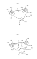
また、上記実施形態では電極パッドと電気ケーブルとは着脱可能に形成しているが、図7(a)に示す心電測定用電極ユニットYのように、電気ケーブルの電線を直接電極パッド10の電極に電気的に連結して一体のものとして形成することもできる。また、電気ケーブルを用いる代わりに、図7(b)に分解斜視図を示す心電測定用電極ユニットZのように、電極パッド10に対して心電図モニターに無線で信号を送る無線機40を接続するようにしてもよい。この場合、無線機内において、プラス電極とマイナス電極との間に抵抗値差を設けるようにすることができる。さらに、電気ケーブルとコネクターとを着脱可能とすることもできる。例えば、電気ケーブルを既存の先端にワニ口クリップが設けられた3本の電線として、各ワニ口クリップを、コネクターを構成する電線のそれぞれの基端に係合させるような方法が採用できる。
それから、3つの電極の配置は上記実施形態では正三角形の頂点に位置するように配置しているが、他の三角形の頂点に位置するように配置してもよく、実験では直列に並べて胸骨上に貼り付けても心電図を得ることができたので、3つの電極を直列に並べることもできる。電極を直列に並べて胸骨上に貼り付ける場合、ほとんど筋電図が混入しないという利点がある。
さらに、電極パッドの材質は上記実施形態ではシート体を用いているが、板体を用いることができる。この場合、板体は硬いものでなく十分に変形可能なものとすることが望ましい。
In the above embodiment, the resistance value difference is provided between the plus electrode and the minus electrode in the
Moreover, in the said embodiment, although the electrode pad is affixed on a body with an adhesive, various means are employable if it can fix so that an electrode may contact the body surface. For example, like the
Then, a suction cup 33 may be provided on the bottom surface of the connector as in the connector 30A shown in FIG. When the
Furthermore, the method of engaging the
Moreover, in the said embodiment, although the electrode pad and the electric cable are formed so that attachment or detachment is possible, like the electrode unit Y for electrocardiogram measurement shown in FIG. It can also be formed as an integral unit by being electrically connected to the electrodes. Further, instead of using an electric cable, a
Then, in the above embodiment, the three electrodes are arranged so as to be located at the apex of an equilateral triangle, but may be arranged so as to be located at the apex of another triangle. Since the electrocardiogram could be obtained even if it was affixed to, three electrodes could be arranged in series. When the electrodes are arranged in series and pasted on the sternum, there is an advantage that almost no electromyogram is mixed.
Furthermore, although the sheet pad is used as the material of the electrode pad in the above embodiment, a plate body can be used. In this case, it is desirable that the plate is not hard and can be sufficiently deformed.
X、Y、Z 心電測定用電極ユニット
10、10A、10B 電極パッド
12a、12b、12c 電極
13a、13b、13c 端子
20 電気ケーブル
30、30A コネクター
31a、31b、31c リング
X, Y, Z Electrocardiographic
Claims (11)
前記プラス電極、マイナス電極及びアース電極のそれぞれ電気的に連結する3本の電線を有し、双極誘導を用いる心電図モニターに接続できる電気ケーブルとを有し、
前記プラス電極から前記心電図モニターに至るまでの電気抵抗値が、前記マイナス電極から前記心電図モニターに至るまでの電気抵抗値よりも小さくなるよう形成される
心電測定用電極ユニット。 An electrode pad consisting of a single sheet or plate and fixing the positive electrode, the negative electrode, and the ground electrode so as to be exposed on the back side, wherein the electrodes are in contact with the surface of the human body. An electrode pad formed so that the back side can be fixed to the human body surface;
Having three electric wires that are electrically connected to each of the positive electrode, the negative electrode, and the ground electrode, and having an electric cable that can be connected to an electrocardiogram monitor using bipolar induction;
An electrocardiogram measurement electrode unit formed such that an electrical resistance value from the plus electrode to the electrocardiogram monitor is smaller than an electrical resistance value from the minus electrode to the electrocardiogram monitor.
前記無線装置には、前記各端子に係合して電気的に接続するコネクタが設けられることで、前記電極パッドと前記無線装置とは着脱可能に形成される請求項2に記載の心電測定用電極ユニット。 In place of the electrical cable, a wireless device is provided that is connected to the positive electrode, the negative electrode, and the ground electrode, and wirelessly transmits an electrical signal from the positive electrode, the negative electrode, and the ground electrode to the electrocardiogram monitor,
The electrocardiogram measurement according to claim 2, wherein the wireless device is provided with a connector that is engaged with and electrically connected to each terminal, so that the electrode pad and the wireless device are detachable. Electrode unit.
前記コネクタは前記フックに掛る前記電気ケーブルに接続される導電性のリング又はフックから形成され、前記端子の導電性フックに掛った状態において弾性体によって掛りがはずれない方向に付勢される
請求項4に記載の心電測定用電極ユニット。 The terminals are arranged in a triangular shape, and each terminal is formed with a conductive hook whose tip is directed in the direction of the nearest corner of the triangle with respect to the base end,
The connector is formed of a conductive ring or hook connected to the electric cable hooked on the hook, and is biased in a direction not to be hooked by an elastic body when hooked on the conductive hook of the terminal.
The electrode unit for electrocardiogram measurement according to claim 4 .
Priority Applications (1)
| Application Number | Priority Date | Filing Date | Title |
|---|---|---|---|
| JP2015249853A JP6234425B2 (en) | 2015-12-22 | 2015-12-22 | Electrocardiograph electrode unit, electrode pad and electric cable |
Applications Claiming Priority (1)
| Application Number | Priority Date | Filing Date | Title |
|---|---|---|---|
| JP2015249853A JP6234425B2 (en) | 2015-12-22 | 2015-12-22 | Electrocardiograph electrode unit, electrode pad and electric cable |
Publications (2)
| Publication Number | Publication Date |
|---|---|
| JP2017113141A JP2017113141A (en) | 2017-06-29 |
| JP6234425B2 true JP6234425B2 (en) | 2017-11-22 |
Family
ID=59233211
Family Applications (1)
| Application Number | Title | Priority Date | Filing Date |
|---|---|---|---|
| JP2015249853A Active JP6234425B2 (en) | 2015-12-22 | 2015-12-22 | Electrocardiograph electrode unit, electrode pad and electric cable |
Country Status (1)
| Country | Link |
|---|---|
| JP (1) | JP6234425B2 (en) |
Families Citing this family (2)
| Publication number | Priority date | Publication date | Assignee | Title |
|---|---|---|---|---|
| JP7090354B2 (en) | 2018-03-29 | 2022-06-24 | 株式会社クリエイティブテクノロジー | Suction pad |
| JP2020121230A (en) * | 2020-05-25 | 2020-08-13 | アトムメディカル株式会社 | Biological information detection device |
Family Cites Families (4)
| Publication number | Priority date | Publication date | Assignee | Title |
|---|---|---|---|---|
| US6117077A (en) * | 1999-01-22 | 2000-09-12 | Del Mar Medical Systems, Llc | Long-term, ambulatory physiological recorder |
| JP3867168B2 (en) * | 2002-04-16 | 2007-01-10 | アドバンスドメディカル株式会社 | Electrocardiograph |
| JP4855734B2 (en) * | 2005-08-15 | 2012-01-18 | フクダ電子株式会社 | Electrocardiogram measurement electrode and electrocardiogram measurement device |
| US9439599B2 (en) * | 2011-03-11 | 2016-09-13 | Proteus Digital Health, Inc. | Wearable personal body associated device with various physical configurations |
-
2015
- 2015-12-22 JP JP2015249853A patent/JP6234425B2/en active Active
Also Published As
| Publication number | Publication date |
|---|---|
| JP2017113141A (en) | 2017-06-29 |
Similar Documents
| Publication | Publication Date | Title |
|---|---|---|
| US8838198B2 (en) | Electrode system | |
| US20100234715A1 (en) | Garment for measuring physiological signals and method of fabricating the same | |
| US20170319132A1 (en) | Devices and methods for use with physiological monitoring garments | |
| JP6383515B2 (en) | Equipment for electrode assembly | |
| JP2018528841A (en) | Flexible textile ribbon connector for clothing with sensor and electronics | |
| US7215989B1 (en) | Multiple electrode assembly | |
| GB1566211A (en) | Ecg montoring | |
| JP2013252180A (en) | Biological electrode and biological electrode roll | |
| JP6234425B2 (en) | Electrocardiograph electrode unit, electrode pad and electric cable | |
| CN103948388A (en) | Myoelectricity collecting device | |
| CN209003993U (en) | Electrode for Electrophysiological mapping | |
| CN204767032U (en) | Flexible neural little electrode array | |
| JP2018078949A (en) | Biological signal detection device and biological signal detection method | |
| CN103211592A (en) | Device for placing electrocardio measuring electrode and electrocardiogram instrument | |
| JPWO2013088747A1 (en) | Biological information detection unit | |
| CN202515658U (en) | Medical electrode | |
| CN209032353U (en) | Radio electrocardiographicmonitoring monitoring lead device | |
| US20200281496A1 (en) | Sensor assembly for patient monitoring systems | |
| JP6235501B2 (en) | Biological signal measurement clothing | |
| CN209595744U (en) | A kind of film structure and electrocardiograph monitoring device | |
| SE7906665L (en) | CONTACT DEVICE FOR MUSCLE STIMULATION | |
| CN209629647U (en) | Easily join wireless electrocardiograph lead device | |
| JPH0482533A (en) | Bioelectrode apparatus for animal | |
| JP3215215U (en) | wrist strap | |
| WO2016121349A1 (en) | Electrode device |
Legal Events
| Date | Code | Title | Description |
|---|---|---|---|
| A521 | Request for written amendment filed |
Free format text: JAPANESE INTERMEDIATE CODE: A523 Effective date: 20170425 |
|
| TRDD | Decision of grant or rejection written | ||
| A01 | Written decision to grant a patent or to grant a registration (utility model) |
Free format text: JAPANESE INTERMEDIATE CODE: A01 Effective date: 20171002 |
|
| A61 | First payment of annual fees (during grant procedure) |
Free format text: JAPANESE INTERMEDIATE CODE: A61 Effective date: 20171024 |
|
| R150 | Certificate of patent or registration of utility model |
Ref document number: 6234425 Country of ref document: JP Free format text: JAPANESE INTERMEDIATE CODE: R150 |
|
| R250 | Receipt of annual fees |
Free format text: JAPANESE INTERMEDIATE CODE: R250 |
|
| R250 | Receipt of annual fees |
Free format text: JAPANESE INTERMEDIATE CODE: R250 |
|
| R250 | Receipt of annual fees |
Free format text: JAPANESE INTERMEDIATE CODE: R250 |
|
| R250 | Receipt of annual fees |
Free format text: JAPANESE INTERMEDIATE CODE: R250 |