JP6226578B2 - Image coding apparatus, image coding method, and program - Google Patents
Image coding apparatus, image coding method, and program Download PDFInfo
- Publication number
- JP6226578B2 JP6226578B2 JP2013124593A JP2013124593A JP6226578B2 JP 6226578 B2 JP6226578 B2 JP 6226578B2 JP 2013124593 A JP2013124593 A JP 2013124593A JP 2013124593 A JP2013124593 A JP 2013124593A JP 6226578 B2 JP6226578 B2 JP 6226578B2
- Authority
- JP
- Japan
- Prior art keywords
- block
- evaluation value
- sub
- image
- blocks
- Prior art date
- Legal status (The legal status is an assumption and is not a legal conclusion. Google has not performed a legal analysis and makes no representation as to the accuracy of the status listed.)
- Active
Links
Images


Classifications
-
- H—ELECTRICITY
- H04—ELECTRIC COMMUNICATION TECHNIQUE
- H04N—PICTORIAL COMMUNICATION, e.g. TELEVISION
- H04N19/00—Methods or arrangements for coding, decoding, compressing or decompressing digital video signals
- H04N19/10—Methods or arrangements for coding, decoding, compressing or decompressing digital video signals using adaptive coding
- H04N19/134—Methods or arrangements for coding, decoding, compressing or decompressing digital video signals using adaptive coding characterised by the element, parameter or criterion affecting or controlling the adaptive coding
- H04N19/154—Measured or subjectively estimated visual quality after decoding, e.g. measurement of distortion
-
- H—ELECTRICITY
- H04—ELECTRIC COMMUNICATION TECHNIQUE
- H04N—PICTORIAL COMMUNICATION, e.g. TELEVISION
- H04N19/00—Methods or arrangements for coding, decoding, compressing or decompressing digital video signals
- H04N19/10—Methods or arrangements for coding, decoding, compressing or decompressing digital video signals using adaptive coding
- H04N19/102—Methods or arrangements for coding, decoding, compressing or decompressing digital video signals using adaptive coding characterised by the element, parameter or selection affected or controlled by the adaptive coding
- H04N19/124—Quantisation
-
- H—ELECTRICITY
- H04—ELECTRIC COMMUNICATION TECHNIQUE
- H04N—PICTORIAL COMMUNICATION, e.g. TELEVISION
- H04N19/00—Methods or arrangements for coding, decoding, compressing or decompressing digital video signals
- H04N19/10—Methods or arrangements for coding, decoding, compressing or decompressing digital video signals using adaptive coding
- H04N19/134—Methods or arrangements for coding, decoding, compressing or decompressing digital video signals using adaptive coding characterised by the element, parameter or criterion affecting or controlling the adaptive coding
- H04N19/136—Incoming video signal characteristics or properties
- H04N19/14—Coding unit complexity, e.g. amount of activity or edge presence estimation
-
- H—ELECTRICITY
- H04—ELECTRIC COMMUNICATION TECHNIQUE
- H04N—PICTORIAL COMMUNICATION, e.g. TELEVISION
- H04N19/00—Methods or arrangements for coding, decoding, compressing or decompressing digital video signals
- H04N19/10—Methods or arrangements for coding, decoding, compressing or decompressing digital video signals using adaptive coding
- H04N19/169—Methods or arrangements for coding, decoding, compressing or decompressing digital video signals using adaptive coding characterised by the coding unit, i.e. the structural portion or semantic portion of the video signal being the object or the subject of the adaptive coding
- H04N19/17—Methods or arrangements for coding, decoding, compressing or decompressing digital video signals using adaptive coding characterised by the coding unit, i.e. the structural portion or semantic portion of the video signal being the object or the subject of the adaptive coding the unit being an image region, e.g. an object
- H04N19/176—Methods or arrangements for coding, decoding, compressing or decompressing digital video signals using adaptive coding characterised by the coding unit, i.e. the structural portion or semantic portion of the video signal being the object or the subject of the adaptive coding the unit being an image region, e.g. an object the region being a block, e.g. a macroblock
Landscapes
- Engineering & Computer Science (AREA)
- Multimedia (AREA)
- Signal Processing (AREA)
- Compression Or Coding Systems Of Tv Signals (AREA)
Description
本発明は画像符号化装置、画像符号化方法及びプログラムに関し、特に画面内の適応的な符号量制御に関する。 The present invention relates to an image encoding device, an image encoding method, and a program, and more particularly to adaptive code amount control in a screen.
動画像の圧縮記録に用いられる符号化方式として、H.264/MPEG−4 AVC(以下H.264)が知られている。(非特許文献1)
H.264においては、画像をブロック単位に符号化を行うが、画像を量子化する際に使用する量子化パラメータは、ブロック毎に可変である。この量子化パラメータを制御する事によって、ブロックに割り当てる符号量を変えて画質を制御する事ができる。
As an encoding method used for compression recording of moving images, H.264 is used. H.264 / MPEG-4 AVC (hereinafter referred to as H.264) is known. (Non-Patent Document 1)
H. In H.264, an image is encoded in units of blocks, but a quantization parameter used when quantizing an image is variable for each block. By controlling this quantization parameter, the image quality can be controlled by changing the amount of code assigned to the block.
特許文献1で開示された技術では、圧縮する画像の複雑さや滑らかさを示す指標値を基に、圧縮処理による画質劣化が視覚的に目立ちやすい、画像が単調で滑らかな領域(以下、平坦領域)が高画質になるよう制御している。同様に特許文献1の開示技術では、画質劣化の目立ちにくい、画像が複雑な領域(以下、非平坦領域)が低画質になるよう制御している。なお、画像の複雑度の判定には、ブロックの輝度の平均値と各画素の輝度の差分値を用いている。以上述べたような適応的な画質制御により、特許文献1の技術は、画質の最適化を図っている。
In the technique disclosed in
また、特許文献1の開示技術では、平坦領域を判定する指標値を、ブロックをさらに分割したサブブロック単位で求めることで、ブロック内に平坦領域と非平坦領域が混在する場合でも平坦領域を検出することを可能としている。
In addition, the disclosed technique disclosed in
以下、図6を用いて特許文献1における平坦領域判定による画質制御について説明する。図6は、白い背景に黒いオブジェクトが存在している画像を示しており、実線で表される個々の正方形は16×16画素のブロックを表す。601は、白い背景の一部のブロック(白ブロック)であり、該ブロックに属する画素の画素値は全て大きいためブロックの複雑度は低い。603は、黒いオブジェクトの一部のブロック(黒ブロック)であり、該ブロックに属する画素の画素値は全て小さいためブロックの複雑度は低い。ここで、602は、白いブロックと黒いブロックの境界に位置するブロックである。ブロック602は、黒い画素と白い画素が混在するため、ブロックの輝度の平均値と各画素の輝度の差分値が大きく複雑度が高い。そのため、単にブロック単位の複雑度をもとに平坦領域の判定を行い、量子化パラメータを決定する場合には、複雑度が高いブロックの量子化パラメータは大きく設定されることになる。しかし、ブロック602のように、境界に位置するブロックは一般的に画質の劣化が目立ち易く、量子化パラメータは小さく設定する事が望ましい。
Hereinafter, image quality control by flat area determination in
ここで、図6中に点線で表されるように、各ブロックを8x8画素のサブブロックに分割を行うと、ブロック602の各サブブロックは、全画素が黒いサブブロック2個と、全画素が白いサブブロック2個で構成されることになる。すなわち、サブブロック単位で見た場合の複雑度はブロック601やブロック603と同等になる。このように、サブブロック単位に複雑度を求めることで、画質劣化の目立ち易い境界ブロックであるか否かを判定する事ができ、量子化パラメータを大きく設定して画質が劣化する事を防ぐ事ができる。
When each block is divided into 8 × 8 pixel sub-blocks as represented by dotted lines in FIG. 6, each sub-block of the
しかしながら、特許文献1に示した制御方法では、平坦領域を決定するための指標値をサブブロックの個数だけ計算することが必要となり、計算コストが増大する。また、特許文献1に示した制御方法では、平坦領域と判定されたサブブロックが存在するブロックは全て高画質になるよう制御するため、高画質にするブロックの割合が増えてしまう。この場合、平坦領域の高画質化による全体の符号量の増大度合いが高くなるため、符号量が限られた条件下では、平坦領域をあまり高画質に出来ないという問題があった。
However, in the control method shown in
以下、図11、図12を用いて特許文献1における画質制御の課題について説明する。図11は、ブロック単位に求めた複雑度順に1101〜1107の各ブロックを配置したものであり、ブロックはそれぞれの複雑度に応じて平坦領域の判定を受け、量子化パラメータが決定される。以上述べたような複雑度による分類および量子化パラメータの決定を、ブロックを4分割したサブブロック単位で行った場合を図12に示す。サブブロック単位に複雑度を求めた場合、ブロック1105以外のブロック内のサブブロックはすべて同一画素で構成されるため、複雑度は一様になってしまう。すなわち平坦領域と判定されるブロックが増えるため、量子化パラメータを低くして高画質に符号化することで全体の符号量が増大してしまうことになる。
Hereinafter, the problem of image quality control in
したがって、本発明は、視覚劣化が目立ちにくいブロックの符号量を減らし、劣化が目立ちやすいブロックに多くの符号量を割り当てて高画質にすることを目的とする。更に、高画質にするブロックの数を抑えて全体符号量の増大を防ぐことを目的とする。 Therefore, an object of the present invention is to reduce the code amount of a block that is less prominent in visual deterioration and to allocate a large amount of code to a block that is conspicuous in deterioration to achieve high image quality. It is another object of the present invention to prevent an increase in the total code amount by suppressing the number of blocks for high image quality.
上述の課題を解決するため、本発明の画像符号化装置は、入力された画像をブロック単位に符号化する符号化手段と、前記ブロックに対応したブロック評価値を算出するブロック評価値算出手段と、前記ブロックをN個(Nは2以上の自然数)のサブブロックに分割し、前記サブブロックに対応したサブブロック評価値を算出するサブブロック評価値算出手段と、前記ブロック評価値と前記サブブロック評価値とを用いて、前記ブロックの量子化パラメータを決定する決定手段と、を有し、前記決定手段が用いる前記サブブロック評価値は、第1の種類の評価値であり、前記決定手段が用いる前記ブロック評価値は、前記第1の種類とは異なる第2の種類の評価値を少なくとも含む。 In order to solve the above-described problem, an image encoding device of the present invention includes an encoding unit that encodes an input image in units of blocks, and a block evaluation value calculation unit that calculates a block evaluation value corresponding to the block. , The block is divided into N (N is a natural number of 2 or more) sub-blocks, sub-block evaluation value calculating means for calculating a sub-block evaluation value corresponding to the sub-block, the block evaluation value and the sub-block by using the evaluation value, have a, a determination unit configured to determine a quantization parameter of the block, the determination unit uses the sub-block evaluation value is an evaluation value of the first type, said determining means The block evaluation value to be used includes at least a second type evaluation value different from the first type.
本発明により、視覚劣化が目立ちにくいブロックの符号量を減らし、劣化が目立ちやすいブロックに多くの符号量を割り当てて高画質にすることで、主観的な画質が向上する。また、全てのブロックに対してサブブロック単位の判定をしなくて済むため、計算量を減らせるとともに、高画質にするブロック数の増大を抑えることが可能になる。 According to the present invention, the subjective image quality is improved by reducing the code amount of a block in which visual deterioration is not conspicuous and allocating a large amount of code to a block in which deterioration is conspicuous to obtain a high image quality. In addition, since it is not necessary to perform determination in units of sub-blocks for all blocks, it is possible to reduce the amount of calculation and to suppress an increase in the number of blocks that achieve high image quality.
以下、添付の図面を参照して、本発明をその好適な実施形態に基づいて詳細に説明する。なお、以下の実施形態において示す構成は一例に過ぎず、本発明は図示された構成に限定されるものではない。 Hereinafter, the present invention will be described in detail based on preferred embodiments with reference to the accompanying drawings. The configurations shown in the following embodiments are merely examples, and the present invention is not limited to the illustrated configurations.
<実施形態1>
以下、本発明の第一の実施形態を、図面を用いて説明する。図1は本実施形態の画像符号化装置を示すブロック図である。
<
Hereinafter, a first embodiment of the present invention will be described with reference to the drawings. FIG. 1 is a block diagram showing an image encoding apparatus according to this embodiment.
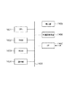
図1において、101は、入力画像の評価値を算出するブロック評価値算出部である。ブロック評価値算出部101にはブロック単位に画像が入力され、前記ブロック毎のブロック評価値が算出される。102は、複数の前記ブロック評価値を基にブロック判別情報を生成するブロック判別部である。103は、前記ブロック判別情報に基づいて、ブロックの量子化パラメータを決定する制御部である。104は、入力された画像を符号化する符号化部である。符号化部104には、ブロック単位に画像が入力され、制御部103から生成された量子化パラメータに基づいてブロックが符号化され、符号化ストリームが生成される。サブブロック評価値算出部105はブロック単位の画像を入力とし、前記ブロックを複数のサブブロックに分割し、各サブブロックについてサブブロック評価値を算出する。
In FIG. 1,
本実施形態の画像符号化装置の動作を、図2のフローチャートを用いて詳細に説明する。本実施形態では動画像データはフレーム単位に入力され、ブロックに分割されてラスタ順に処理される。しかし本発明はこれに限定されるものではなく、例えばフレームを分割したスライス単位に画像を入力しても構わない。また、本実施形態におけるブロックのサイズは16×16画素とするが、本発明はこれに限定されるものではなく、例えば8×8画素や32×32画素でもよく、32×16画素のようなサイズでもよい。 The operation of the image coding apparatus according to the present embodiment will be described in detail with reference to the flowchart of FIG. In this embodiment, moving image data is input in units of frames, divided into blocks, and processed in raster order. However, the present invention is not limited to this. For example, an image may be input in units of slices obtained by dividing a frame. The block size in the present embodiment is 16 × 16 pixels, but the present invention is not limited to this, and may be 8 × 8 pixels or 32 × 32 pixels, such as 32 × 16 pixels. It may be size.
ステップS201において、ブロック評価値算出部101は、入力されたブロックのブロック評価値を算出する。ブロック評価値は、処理対象のブロックを符号化した時の画質指標に関するものとする。ここで、画質指標とは、ブロックを符号化する際に生じる量子化誤差が人間の視覚に影響を与える度合いであり、評価値はこの度合いを判定するために算出される。本実施形態では、ブロックに属する各画素の輝度の平均値及び輝度の複雑度をブロック評価値として算出する。輝度の複雑度には、ブロックに属する各画素の輝度値と該ブロックの輝度の平均値との差分の大きさ(絶対値)の合計値を用いる。しかし、本発明の画像符号化装置はこれに限定されるものではなく、人間の視覚に与える度合いを判定できる指標であればよい。例えば輝度の分散、色差の平均値、複雑度、分散等を算出してもよいし、動きベクトル、予測誤差等の符号化結果を指標として用いてもよい。また、算出されるブロック評価値の数は2種類に限定されるものではなく、輝度の平均値と複雑度に加えて、色差の平均値等、他のブロック評価値を算出する事も可能である。
In step S201, the block evaluation
また、S201において、サブブロック評価値算出部105は、入力されたブロックを複数個のサブブロックに分割し、サブブロック評価値を算出する。サブブロック評価値は、ブロック評価値と同様に、処理対象を符号化した時の画質指標に関するものとする。本実施形態では、輝度の複雑度として、サブブロックに属する各画素の輝度値と該ブロックの輝度の平均値との差分の大きさ(絶対値)の合計値を用いる。また、本実施形態では、各サブブロックについて輝度の複雑度を求めたのち、その最小値を前記サブブロック評価値として算出する。しかし、本発明の画像符号化装置におけるサブブロック評価値の算出方法はこれに限定されるものではなく、人間の視覚に与える度合いを判定できる指標であればよいし、同様に、サブブロック毎の最小値でなくてもよい。
In S201, the sub-block evaluation
ステップS202において、ブロック判別部102は、前記ブロック評価値を基に当該ブロックに対してブロック判別情報を生成する。ブロック判別情報の生成方法の詳細に関しては後述する。
In step S202, the
ステップS203において、制御部103は、前記サブブロック評価値および前記ブロック判別情報に基づき、当該ブロックの属性に対応した量子化パラメータを生成する。量子化パラメータの生成方法の詳細に関しては後述する。
In step S203, the
ステップS204において、符号化部104は、前記量子化パラメータに基づいてブロックを符号化し、符号化ストリームを生成する。
In step S204, the
ステップS205では、フレーム内の全てのブロックが符号化されたか否かが判定される。全てのブロックが符号化されたならば(ステップS205でYes)、フレームの符号化処理を終了する。全てのブロックが符号化されていなければ(ステップS205でNo)、ステップS201の処理に進み後続のブロックを符号化する。 In step S205, it is determined whether all blocks in the frame have been encoded. If all the blocks have been encoded (Yes in step S205), the frame encoding process ends. If all the blocks are not encoded (No in step S205), the process proceeds to step S201, and the subsequent blocks are encoded.
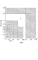
次に本実施形態におけるブロック判別情報の生成方法(ステップS202)を説明する。本実施形態では、ブロックの輝度の平均値S1と輝度の複雑度S2から成る2個のブロック評価値を、ブロック判別情報の生成に用いる。また、評価値S1,S2それぞれに対し閾値配列T1,T2を定義する。k個の評価値S1,S2,…,Sk毎にそれぞれ閾値配列Tkが保持される。図7に、輝度の平均値及び複雑度を評価値とした際のブロックの判別の一例を示す。横軸は複雑度S2、縦軸は輝度の平均値S1であり、計72個の領域に分割されている。T1、T2はそれぞれの領域を定義する閾値の組で構成される。図7の例ではT1={T1[1],T1[2],T1[3],T1[4],T1[5],T1[6],T1[7],T1[8],T1[9]}である。また、T2={T2[1],T2[2],T2[3],T2[4],T2[5],T2[6],T2[7],T2[8]}である。また、ブロック判別情報Pとして、当該ブロックが各評価値のどの領域に位置するかを、領域を定義する閾値の組であらわす。例えば図7において斜線で示した領域はP={T1[6],T2[5]}である。 Next, a method for generating block discrimination information (step S202) in the present embodiment will be described. In the present embodiment, two block evaluation values including an average value S1 of luminance of blocks and a complexity S2 of luminance are used for generating block discrimination information. Further, threshold arrays T1 and T2 are defined for the evaluation values S1 and S2, respectively. A threshold value array Tk is held for each of the k evaluation values S1, S2,. FIG. 7 shows an example of block discrimination when the average value and complexity of luminance are used as evaluation values. The horizontal axis represents complexity S2, and the vertical axis represents luminance average value S1, which is divided into a total of 72 regions. T1 and T2 are constituted by a set of threshold values that define each region. In the example of FIG. 7, T1 = {T1 [1], T1 [2], T1 [3], T1 [4], T1 [5], T1 [6], T1 [7], T1 [8], T1 [ 9]}. Further, T2 = {T2 [1], T2 [2], T2 [3], T2 [4], T2 [5], T2 [6], T2 [7], T2 [8]}. Further, as the block discrimination information P, the region of each evaluation value in which the block is located is represented by a set of threshold values that define the region. For example, the hatched area in FIG. 7 is P = {T1 [6], T2 [5]}.
図3のフローチャートを用いてブロック判別情報の生成方法(ステップS202)を詳細に説明する。まず、ステップS301では、変数iが1に、ステップS302では、変数jが1に初期化される。次に、ステップS303では、評価値Siが閾値Ti[j]で定義される領域内に属しているか否かが判定される。評価値Siが閾値Tk[i]に属しているならば(ステップS303でYes)ステップS306の処理に進み、そうでないならばステップS304の処理に進む。次に、ステップS304では変数jに1が加算される。 The block discrimination information generation method (step S202) will be described in detail with reference to the flowchart of FIG. First, in step S301, the variable i is initialized to 1, and in step S302, the variable j is initialized to 1. Next, in step S303, it is determined whether or not the evaluation value Si belongs to an area defined by the threshold value Ti [j]. If the evaluation value Si belongs to the threshold value Tk [i] (Yes in step S303), the process proceeds to step S306, and if not, the process proceeds to step S304. Next, in step S304, 1 is added to the variable j.
次にステップS305では、評価値Siを全ての閾値(閾値配列Tiに属するすべての閾値)と比較したか否かが判定される。全ての閾値と比較したならば(ステップS305でYes)ステップS306の処理に進み、そうでないならばステップS303の処理に進む。ステップS306では、評価値Siにおけるブロック判別情報Pi(ブロック判別情報Pのi番目の要素)に、当該評価値について属していると判定された閾値が代入され、ステップS307に進む。ステップS307では、変数iに1が加算され、ステップS308に進む。ステップS308では、変数iがkより大きい、すなわちk個の評価値全てにおいて閾値との比較がなされたかどうかを判定する。全ての比較が終わっていれば(ステップS308でYes)ステップS309に、終わっていなければ(ステップS308でNo)ステップS302に進む。 Next, in step S305, it is determined whether or not the evaluation value Si has been compared with all threshold values (all threshold values belonging to the threshold array Ti). If all the threshold values have been compared (Yes in step S305), the process proceeds to step S306. If not, the process proceeds to step S303. In step S306, the threshold value determined to belong to the evaluation value is substituted into the block determination information Pi (i-th element of the block determination information P) in the evaluation value Si, and the process proceeds to step S307. In step S307, 1 is added to the variable i, and the process proceeds to step S308. In step S308, it is determined whether the variable i is larger than k, that is, whether or not all the k evaluation values have been compared with the threshold value. If all comparisons have been completed (Yes in step S308), the process proceeds to step S309, and if not completed (No in step S308), the process proceeds to step S302.
ステップS309では、ブロック判別情報Pに各評価値について属していると判定された閾値の組が代入され、ブロック判別情報の生成を終了する。このようにして生成したブロック判別情報は当該ブロックが図7の格子状の領域のどの部分に位置されるかを示しており、このブロック判別情報にブロックの特性および特性に適した量子化パラメータを対応付ける。 In step S309, a set of threshold values determined to belong to each evaluation value is substituted into the block determination information P, and the generation of the block determination information is terminated. The block discriminating information generated in this way indicates in which part of the grid area shown in FIG. 7 the block is located, and the block discriminating information includes quantization characteristics suitable for the block characteristics and characteristics. Associate.
本実施形態においてブロック判別情報の生成は、処理対象ブロックの画質劣化度合いを判定するために行われる。例えば、人間の目は高い空間周波数の画像よりも低い空間周波数の画像のほうが、画質の劣化に対して敏感である。そのため、前記複雑度が低いブロックは空間周波数も低く、量子化誤差による画質劣化が人の視覚に目立ち易く、複雑度が高いブロックは空間周波数が高く画質劣化が目立ちにくい。輝度の平均値も同様で、暗い領域の方が人の視覚に対して画質劣化が目立ち易く、明るい領域は画質劣化が目立ちにくいといった特性を持つ。これら複数の評価値をもとに、例えば図7の左下の領域は画質劣化の目立ちやすい領域であるため量子化パラメータを小さくして画質劣化を抑える。同時に図7の右上の画質劣化の目立ちづらい領域の量子化パラメータを大きくして全体の符号量の上昇を抑えることで、同等のビットレートを保ったまま主観的な画質を向上させることが可能となる。 In the present embodiment, the block discrimination information is generated in order to determine the degree of image quality degradation of the processing target block. For example, human eyes are more sensitive to image quality degradation in lower spatial frequency images than in higher spatial frequency images. For this reason, the block with low complexity has a low spatial frequency, and image quality deterioration due to quantization error is easily noticeable to human vision, and a block with high complexity has high spatial frequency and image quality deterioration is hardly noticeable. The average value of the luminance is the same, and the dark region has a characteristic that image quality deterioration is more conspicuous for human vision, and the bright region has less characteristic of image quality deterioration. Based on the plurality of evaluation values, for example, the lower left area in FIG. 7 is an area in which image quality deterioration is conspicuous, so that the quantization parameter is reduced to suppress image quality deterioration. At the same time, it is possible to improve the subjective image quality while maintaining the same bit rate by increasing the quantization parameter in the region where the image quality degradation is not noticeable in the upper right of FIG. Become.
次に図4のフローチャートを用いて本実施形態における量子化パラメータの生成方法(ステップS203)を詳細に説明する。まず、ステップS401では、ステップS202で生成されたブロック判別情報が、特定の条件を満たすかどうかを判定する。特定の条件を満たす場合(ステップS401でYes)、ステップS402において、サブブロック評価値を用いて、サブブロックの特性に適した量子化パラメータが対応づけられる。 Next, the quantization parameter generation method (step S203) in the present embodiment will be described in detail with reference to the flowchart of FIG. First, in step S401, it is determined whether the block discrimination information generated in step S202 satisfies a specific condition. When a specific condition is satisfied (Yes in step S401), in step S402, a quantization parameter suitable for the characteristics of the sub-block is associated using the sub-block evaluation value.
ここで特定の条件とは、ブロック単位の画質指標をもとに決定されたブロック判別情報の結果、サブブロック単位の画質指標の評価が必要と判定されたことを指す。例えば、図7の右上の領域(ブロックに属する各画素の輝度の平均値が第1の閾値以上でありかつ輝度の複雑度が第2の閾値以上)と判定された場合、すなわち画質劣化が目立ちづらく、量子化パラメータを大きくできる可能性のある領域と判定された場合である。ただし、ブロック単位の特性では量子化パラメータを大きくできると判定された場合であっても、サブブロック単位では、例えば前述した平坦な領域が存在し、量子化パラメータを大きくした場合に画質劣化が目立ってしまう場合がある。 Here, the specific condition indicates that it is determined that the evaluation of the image quality index for each sub-block is necessary as a result of the block discrimination information determined based on the image quality index for each block. For example, when it is determined that the area in the upper right of FIG. 7 (the average luminance value of each pixel belonging to the block is equal to or higher than the first threshold value and the luminance complexity is equal to or higher than the second threshold value), that is, image quality degradation is conspicuous. In other words, it is a case where it is determined that the quantization parameter can be increased. However, even if it is determined that the quantization parameter can be increased by the characteristics of the block unit, for example, the above-described flat region exists in the sub-block unit, and image quality degradation is conspicuous when the quantization parameter is increased. May end up.
この問題を回避するため、ステップS402では、サブブロック評価値から導出される量子化パラメータの生成を行う。ステップS401で特定の条件を満たさない場合(ステップS401でNo)、例えば、ブロック単位の特性情報で既に画質劣化が目立ちやすいと判定された場合には、ステップS403に進む。一方、ステップS403では、サブブロック評価値を用いずに量子化パラメータの生成を行う。 In order to avoid this problem, in step S402, a quantization parameter derived from the sub-block evaluation value is generated. If the specific condition is not satisfied in step S401 (No in step S401), for example, if it is determined that the image quality deterioration is already conspicuous with the characteristic information in units of blocks, the process proceeds to step S403. On the other hand, in step S403, the quantization parameter is generated without using the sub-block evaluation value.
ステップS402およびステップS403における量子化パラメータの生成方法の詳細は特に規定しないが、例えばテーブルルックアップ等の処理でブロックの判別結果に1対1に対応した量子化パラメータを返す方法などがある。 The details of the quantization parameter generation method in step S402 and step S403 are not particularly defined. For example, there is a method of returning a quantization parameter corresponding to a block discrimination result in a table lookup process or the like.
ステップS402およびステップS403における処理の結果、視覚劣化が目立ちにくいブロックの符号量を減らし、劣化が目立ちやすいブロックに多くの符号量を割り当てて高画質にすることで、主観的な画質が向上する。また、一部のブロックに対してのみサブブロック単位の判定を行うことで、高画質にするブロック数の増大を抑える。 As a result of the processing in steps S402 and S403, the subjective image quality is improved by reducing the code amount of blocks that are less prominent in visual deterioration and assigning a larger amount of code to blocks that are more prominent in deterioration. In addition, by making the determination in units of sub-blocks only for a part of the blocks, an increase in the number of blocks with high image quality is suppressed.
本実施形態では、ブロック判別情報の評価指標として輝度の平均値と複雑度の2種類を使用し2次元空間の位置情報に基づいて量子化パラメータを設定する例を説明したが、更に評価値をk種類(k>2)に増やしてK次元空間上に拡張してもよい。 In this embodiment, an example in which the quantization parameter is set based on the position information in the two-dimensional space using two types of luminance average value and complexity as the evaluation index of the block discrimination information has been described. The number may be increased to k types (k> 2) and expanded on the K-dimensional space.
<実施形態2>
本発明の第2の実施形態の画像符号化装置について説明する。本実施形態の画像符号化装置の構成は、図1に示した本発明の第1の実施形態の画像符号化装置の構成と同一である。本実施形態では、図2のフローチャートで表される画像符号化装置の動作のうち、ブロック評価値算出(ステップS201の処理)が第1の実施形態と異なる。
<
An image encoding apparatus according to the second embodiment of the present invention will be described. The configuration of the image encoding device of the present embodiment is the same as the configuration of the image encoding device of the first embodiment of the present invention shown in FIG. In the present embodiment, among the operations of the image coding apparatus represented by the flowchart of FIG. 2, the block evaluation value calculation (the process of step S201) is different from the first embodiment.
ステップS201において、ブロック評価値算出部101は、入力されたブロックのブロック評価値を算出する。ブロック評価値として第1の実施形態に記載の指標値に加え、ブロックを更にM個(MはN以下の自然数)に分割したサブブロック毎に指標値を取得し、得られた複数の指標値の中で最小の値をブロック評価値として用いることとする。本実施形態では、サブブロック毎に画素値の分散値を取得し、得られた複数の分散値の中で最小の値を選択する事で決定される指標を用いることとするが、本発明はこれに限定されるものではない。また、S201において、サブブロック評価値算出部105は、入力されたブロックをN個のサブブロックに分割し、サブブロック評価値を算出する。その他のサブブロック評価値算出部に関する説明は第1の実施形態に準ずる。
In step S201, the block evaluation
ステップS202以降の処理に関しては第1の実施形態と同一であるため説明を省略する。また、図3のフローチャートで表されるステップS202のブロック判別情報の生成方法、および図4のフローチャートで表されるステップS203の量子化パラメータの生成方法に関しても第1の実施形態と同一であるため説明を省略する。 Since the processing after step S202 is the same as that of the first embodiment, the description thereof is omitted. Further, the block discrimination information generation method in step S202 represented by the flowchart in FIG. 3 and the quantization parameter generation method in step S203 represented by the flowchart in FIG. 4 are also the same as those in the first embodiment. Description is omitted.
以上述べたように、一部もしくはすべてのブロック評価値をブロックをM分割したサブブロック単位の指標値から算出する、すなわち評価指標算出に用いるブロックの大きさを変えることで、入力画像に応じた画質制御が可能となる。以下、図5を用いて、評価指標算出に用いるブロックの大きさと画質制御の関係について示す。 As described above, some or all of the block evaluation values are calculated from the index values in units of sub-blocks obtained by dividing the block into M, that is, by changing the size of the block used for evaluation index calculation, Image quality control is possible. Hereinafter, the relationship between the block size used for calculating the evaluation index and the image quality control will be described with reference to FIG.
図5において、501は撮影する被写体、502はその部分領域を示しており、本説明では、部分領域502中の白および黒の平坦部分の境界における視覚的な画質劣化に着目する。ブロック符号化結果511は、被写体501を横12ブロック及び縦8ブロックで符号化したとき(以下、符号化結果Aとする)の各ブロックを点線で示しており、部分領域502はブロック512、513,514,515の4ブロックで符号化される。ブロック符号化結果521は被写体501を横6ブロック及び縦4ブロック、すなわち縦横半分のブロック数で符号化したとき(以下、符号化結果Bとする)の各ブロックを点線で示しており、部分領域502はブロック522で符号化される。ここで、各ブロックの大きさ(構成画素数)は符号化結果AおよびBで同一であるとする。ブロック符号化結果531およびブロック532は、符号化結果Bのブロックサイズを縦横2倍に拡大し、再生時の被写体の大きさを符号化結果Aと同等にした場合のイメージを示す。
In FIG. 5,
符号化結果A,Bともにブロック単位で平坦領域の判定をして符号化を行った場合、符号化結果Aにおいては、部分領域中のブロック515の部分(全て黒い画素で構成)は輝度の複雑度のみで平坦領域と判定され、相応の画質制御がなされる。また、ブロック512,513においても、白い画素が多数を占めることから、同様に平坦領域と判定されると考えられる。しかし、符号化結果Bでは部分領域が1ブロックで表されており、ブロック単位の輝度の複雑度だけでは平坦領域と判定することは難しい。すなわち、符号化結果AとBを同一のサイズで視聴した場合に、それぞれの部分領域における画質制御の差異により、符号結果Bでは視覚的な画質劣化が目立ってしまうことが考えられる。よって、符号化結果Bにおいて同様の画質制御を行うためには、評価指標を算出するブロック(サブブロック)の大きさをより小さくすることが望ましい。
When coding results A and B are determined by determining a flat area in units of blocks, in coding result A, the portion of
H.264をはじめ多くの符号化方式では符号化単位であるブロックのサイズは決まっており、ブロック分割数は画像のサイズに比例する。すなわち画像サイズが大きいほどブロック分割数が増え、被写体はより多くのブロックに分割される。このことから、画像サイズに応じて評価指標を算出するブロック(サブブロック)の大きさを変更することが、視覚的な画質劣化の防止に有効であるといえる。 H. In many encoding methods such as H.264, the size of a block which is an encoding unit is determined, and the number of block divisions is proportional to the size of an image. That is, the larger the image size, the greater the number of block divisions, and the subject is divided into more blocks. From this, it can be said that changing the size of the block (sub-block) for calculating the evaluation index according to the image size is effective in preventing visual image quality deterioration.
<実施形態3>
本発明の第3の実施形態の画像符号化装置について、図8のブロック図を用いて説明する。図8の101、102、104に関しては、図1の101、102、104と同一の機能であるため説明を省略する。
<
An image encoding apparatus according to the third embodiment of the present invention will be described with reference to the block diagram of FIG. Since the
803は、ブロック判別情報に基づいて、ブロックの量子化パラメータを決定する制御部である。805はブロック単位の画像を入力とし、前記ブロックを複数のサブブロックに分割し、各サブブロックについてサブブロック評価値を算出するサブブロック評価値算出部である。第1の実施形態の制御部103と異なり、制御部803はブロック判別情報の結果に基づき、サブブロック評価値を算出するか否かを決定し、サブブロック評価値算出部805へと送る。サブブロック評価値算出部805は該決定に基づいてサブブロック評価値を算出する。
A
図13のフローチャートを用いて本実施形態の画像符号化装置の動作を詳細に説明する。図13において、ステップS1301では、ブロック評価値算出部801が入力されたブロックのブロック評価値を算出する。ブロック評価値は、第1の実施形態と同様、処理対象のブロックを符号化した時の画質指標に関するものとする。本実施形態では、ブロックに属する各画素の輝度の平均値及び輝度の複雑度をブロック評価値として算出する。輝度の複雑度には、ブロックに属する各画素の輝度値と該ブロックの輝度の平均値との差分の大きさ(絶対値)の合計値を用いる。 The operation of the image coding apparatus according to the present embodiment will be described in detail using the flowchart of FIG. In FIG. 13, in step S1301, the block evaluation value calculation unit 801 calculates the block evaluation value of the input block. The block evaluation value is related to the image quality index when the block to be processed is encoded, as in the first embodiment. In the present embodiment, the average luminance value and the luminance complexity of each pixel belonging to a block are calculated as a block evaluation value. For the luminance complexity, the total value of the differences (absolute values) between the luminance value of each pixel belonging to the block and the average luminance value of the block is used.
第1の実施形態のステップS201とは異なり、ステップS1301ではサブブロック評価値は算出されない。本実施形態において、サブブロック評価値は後述するステップS1305で算出される。 Unlike step S201 of the first embodiment, the sub-block evaluation value is not calculated in step S1301. In the present embodiment, the sub-block evaluation value is calculated in step S1305 described later.
ステップS1302は、図2のステップS202と同一のため説明を省略する。次に、ステップS1303において、制御部803において判別情報が特定の条件を満たすか否かが判定される。特定の条件を満たす場合(ステップS1303でYes)、ステップS1305の処理に進み、そうでない場合ステップS1304の処理に進む。ここで特定の条件とは、第1の実施形態のステップS401と同様に、ブロック単位の画質指標をもとに決定されたブロック判別情報の結果、サブブロック単位の画質指標の評価が必要と判定されたことを指す。
Step S1302 is the same as step S202 in FIG. In step S1303, the
ステップS1304の処理では、サブブロック単位の画質指標の評価が不要と判断されたため、ステップS1301で算出されたブロック評価値のみから量子化パラメータの生成を行う。一方、ステップS1305の処理では、サブブロック単位の画質指標の評価が必要と判断されたため、サブブロック評価値算出部805においてサブブロック評価値が算出される。サブブロック評価値に関しては第1の実施形態と同様であるため説明を省略する。
In the process of step S1304, since it is determined that the evaluation of the image quality index for each sub-block is unnecessary, the quantization parameter is generated only from the block evaluation value calculated in step S1301. On the other hand, in the process of step S1305, since it is determined that the evaluation of the image quality index for each subblock is necessary, the subblock evaluation
次に、ステップS1306、ステップS1307の処理は図4のステップS402、図2のS204と夫々同一であるため説明を省略する。 Next, steps S1306 and S1307 are the same as steps S402 in FIG. 4 and S204 in FIG.
次に、ステップS1307の処理において、フレームの全てのブロックが符号化されたか否かが判定される。全てのブロックが符号化されたならば(ステップS1307でYes)フレームの符号化処理を終了し、そうでない場合はステップS1301の処理に戻り後続のブロックを符号化する。 Next, in the process of step S1307, it is determined whether all the blocks of the frame have been encoded. If all the blocks have been encoded (Yes in step S1307), the frame encoding process ends. If not, the process returns to step S1301 to encode subsequent blocks.
本実施形態では第1の実施形態とは異なり、ステップS1304で、判別情報が特定の条件を満たす場合のみにサブブロック指標値を生成している。判別情報が特定の条件を満たさない場合は、サブブロック指標値は量子化パラメータの決定に使用されない。そのため常にサブブロック指標値を算出するのは冗長である。本実施形態ではサブブロック評価値算出部805が量子化パラメータの決定に必要な時のみ起動されるため、第1の実施形態と比較した場合に消費電力を削減することができる。
In the present embodiment, unlike the first embodiment, in step S1304, the sub-block index value is generated only when the discrimination information satisfies a specific condition. If the discrimination information does not satisfy a specific condition, the sub-block index value is not used for determining the quantization parameter. Therefore, it is redundant to always calculate the sub-block index value. In this embodiment, since the sub-block evaluation
<実施形態4>
本発明の第4の実施形態の画像符号化装置について説明する。本実施形態の画像符号化装置の構成は、図8に示した本発明の第3の実施形態の画像符号化装置の構成と同一である。本実施形態では、図13のフローチャートで表される画像符号化装置の動作のうち、ブロック評価値算出(ステップS1301の処理)が第3の実施形態と異なる。
<
An image encoding apparatus according to the fourth embodiment of the present invention will be described. The configuration of the image encoding device of the present embodiment is the same as the configuration of the image encoding device of the third embodiment of the present invention shown in FIG. In the present embodiment, among the operations of the image coding apparatus represented by the flowchart in FIG. 13, the block evaluation value calculation (the process of step S1301) is different from the third embodiment.
ステップS1301において、ブロック評価値算出部801は、入力されたブロックのブロック評価値を算出する。ブロック評価値として、第3の実施形態に記載の指標値に加え、ブロックを更にM個(Mは2以上の自然数)に分割した、サブブロック毎に指標値を取得し、得られた複数の指標値の中で最小の値をブロック評価値として用いることとする。 In step S1301, the block evaluation value calculation unit 801 calculates a block evaluation value of the input block. As a block evaluation value, in addition to the index value described in the third embodiment, the block is further divided into M pieces (M is a natural number of 2 or more). The smallest value among the index values is used as the block evaluation value.
本実施形態では、サブブロック毎に画素値の分散値を取得し、得られた複数の分散値の中で最小の値を選択する事で決定される指標を用いることとするが、本発明はこれに限定されるものではない。また、S1305において、サブブロック評価値算出部805は、入力されたブロックをN個(NはMより大きい自然数)のサブブロックに分割し、サブブロック評価値を算出する。その他のサブブロック評価値算出部に関する説明は第3の実施形態に準ずる。ステップS1302以降の処理に関しては第3の実施形態と同一であるため説明を省略する。
In the present embodiment, a dispersion value of pixel values is acquired for each sub-block, and an index determined by selecting the smallest value among a plurality of obtained dispersion values is used. It is not limited to this. In S1305, the sub-block evaluation
以上のように、一部もしくはすべてのブロック評価値をサブブロック単位の指標値から算出する、すなわち評価指標算出に用いるブロックの大きさを変えることで、入力画像に応じた画質制御が可能となる。 As described above, image quality control according to the input image can be performed by calculating a part or all of the block evaluation values from the index value in units of sub-blocks, that is, by changing the size of the block used for evaluation index calculation. .
本実施形態では第2の実施形態とは異なり、ステップS1304で、判別情報が特定の条件を満たす場合のみにサブブロック指標値を生成している。判別情報が特定の条件を満たさない場合は、サブブロック指標値は量子化パラメータの決定に使用されない。そのため常にサブブロック指標値を算出するのは冗長である。本実施形態ではサブブロック評価値算出部805が量子化パラメータの決定に必要な時のみ起動されるため、第2の実施形態と比較した場合に消費電力を削減することができる。
In the present embodiment, unlike the second embodiment, in step S1304, the sub-block index value is generated only when the discrimination information satisfies a specific condition. If the discrimination information does not satisfy a specific condition, the sub-block index value is not used for determining the quantization parameter. Therefore, it is redundant to always calculate the sub-block index value. In this embodiment, since the sub-block evaluation
<実施形態5>
本発明の第5の実施形態の画像符号化装置について説明する。本実施形態の画像符号化装置の構成は、図1に示した本発明の第1の実施形態の画像符号化装置の構成と同一である。また、本実施形態の画像符号化装置の動作に関しても図2,図3,図4のフローチャートで表される第1の実施形態と同一であるため説明を省略する。
<
An image encoding apparatus according to the fifth embodiment of the present invention will be described. The configuration of the image encoding device of the present embodiment is the same as the configuration of the image encoding device of the first embodiment of the present invention shown in FIG. The operation of the image coding apparatus according to the present embodiment is also the same as that of the first embodiment represented by the flowcharts of FIGS.
本実施形態では同様に評価値S1,S2および対応する閾値配列T1,T2に関しても第1の実施形態と同じである。しかし図9で示されるように、実線もしくは破線によって、ブロックの判別結果としての領域の数が72個でなく13個{R1,R2,…,R13}になっていることが異なる。 In the present embodiment, the evaluation values S1, S2 and the corresponding threshold value arrays T1, T2 are similarly the same as those in the first embodiment. However, as shown in FIG. 9, the number of regions as a block discrimination result is not 72 but 13 {R1, R2,..., R13} depending on the solid line or the broken line.
第1の実施形態における領域(図7において閾値配列T1、T2で区切られる各領域を参照)を複数個まとめ、単に閾値との比較を行うだけでブロックの判別を決定しているため、第1の実施形態と比較して多くの場合処理負荷が軽減される。具体的には、第1の実施形態においては72個の領域判定には最大で72回の比較処理が必要になるが、図10で示すように、R1,R2,…,R13の順に領域を判定することで、最大で13回の比較処理で13個の領域判定処理が可能となる。本実施形態では、領域を13個に分割する例を紹介したが、本発明はこれに限定されるものではなく、領域数を増やして更に緻密に画質を制御する事も可能である。 Since a plurality of areas in the first embodiment (refer to the areas separated by the threshold arrays T1 and T2 in FIG. 7) are grouped together and block discrimination is determined by simply comparing with the thresholds, the first In many cases, the processing load is reduced compared to the first embodiment. Specifically, in the first embodiment, 72 regions need to be compared 72 times at maximum, but as shown in FIG. 10, the regions are arranged in the order of R1, R2,..., R13. By making the determination, 13 area determination processes can be performed with a maximum of 13 comparison processes. In the present embodiment, an example in which the area is divided into 13 has been introduced. However, the present invention is not limited to this, and the image quality can be controlled more precisely by increasing the number of areas.
<実施形態6>
図1、図8に示した各処理部はハードウェアでもって構成しているものとして上記実施形態では説明した。しかし、図1、図8に示した各処理部で行なう処理をコンピュータプログラムでもって構成しても良い。
<
Each processing unit shown in FIGS. 1 and 8 has been described in the above embodiment as being configured by hardware. However, the processing performed by each processing unit shown in FIGS. 1 and 8 may be configured by a computer program.
図14は、上記各実施形態に係る画像表示装置に適用可能なコンピュータのハードウェアの構成例を示すブロック図である。CPU1401は、RAM1402やROM1403に格納されているコンピュータプログラムやデータを用いてコンピュータ全体の制御を行うと共に、上記各実施形態に係る画像処理装置が行うものとして上述した各処理を実行する。即ち、CPU1401は、図1、図8に示した各処理部として機能することになる。RAM1402は、外部記憶装置1406からロードされたコンピュータプログラムやデータ、I/F(インターフェース)1407を介して外部から取得したデータなどを一時的に記憶するためのエリアを有する。更に、RAM1402は、CPU1401が各種の処理を実行する際に用いるワークエリアを有する。即ち、RAM1402は、例えば、フレームメモリとして割当てたり、その他の各種のエリアを適宜提供することができる。ROM1403には、本コンピュータの設定データや、ブートプログラムなどが格納されている。操作部1404は、キーボードやマウスなどにより構成されており、本コンピュータのユーザが操作することで、各種の指示をCPU1401に対して入力することができる。表示部1405は、CPU1401による処理結果を出力する。また表示部1405は例えば液晶ディスプレイのような表示装置で構成される。外部記憶装置1406は、ハードディスクドライブ装置に代表される、大容量情報記憶装置である。外部記憶装置1406には、OS(オペレーティングシステム)や、図1、図8に示した各部の機能をCPU1401に実現させるためのコンピュータプログラムが保存されている。更には、外部記憶装置1406は、処理対象としての各画像データや処理結果である符号化データの保存先であっても良い。外部記憶装置1406に保存されているコンピュータプログラムやデータは、CPU1401による制御に従って適宜RAM1402にロードされ、CPU1401による処理対象となる。I/F1407には、LANやインターネット等のネットワーク、投影装置や表示装置などの他の機器を接続することができ、本コンピュータはこのI/F1407を介して様々な情報を取得したり、送出したりすることができる。1408は上述の各部を繋ぐバスである。上述の構成からなる作動は、前述の図2,図3,図4,図13で示したフローチャートで説明した作動をCPU1401が中心となってその制御を行う。
FIG. 14 is a block diagram illustrating a configuration example of computer hardware applicable to the image display apparatus according to each of the above embodiments. The
<その他の実施形態>
本発明の目的は、前述した機能を実現するコンピュータプログラムのコードを記録した記憶媒体を、システムに供給し、そのシステムがコンピュータプログラムのコードを読み出し実行することによっても達成される。この場合、記憶媒体から読み出されたコンピュータプログラムのコード自体が前述した実施形態の機能を実現し、そのコンピュータプログラムのコードを記憶した記憶媒体は本発明を構成する。また、そのプログラムのコードの指示に基づき、コンピュータ上で稼働しているオペレーティングシステム(OS)などが実際の処理の一部または全部を行い、その処理によって前述した機能が実現される場合も含まれる。
<Other embodiments>
The object of the present invention can also be achieved by supplying a storage medium storing a computer program code for realizing the above-described functions to the system, and the system reading and executing the computer program code. In this case, the computer program code itself read from the storage medium realizes the functions of the above-described embodiments, and the storage medium storing the computer program code constitutes the present invention. In addition, the operating system (OS) running on the computer performs part or all of the actual processing based on the code instruction of the program, and the above-described functions are realized by the processing. .
さらに、以下の形態で実現しても構わない。すなわち、記憶媒体から読み出されたコンピュータプログラムコードを、コンピュータに挿入された機能拡張カードやコンピュータに接続された機能拡張ユニットに備わるメモリに書込む。そして、そのコンピュータプログラムのコードの指示に基づき、その機能拡張カードや機能拡張ユニットに備わるCPUなどが実際の処理の一部または全部を行って、前述した機能が実現される場合も含まれる。 Furthermore, you may implement | achieve with the following forms. That is, the computer program code read from the storage medium is written into a memory provided in a function expansion card inserted into the computer or a function expansion unit connected to the computer. Then, based on the instruction of the code of the computer program, the above-described functions are realized by the CPU or the like provided in the function expansion card or function expansion unit performing part or all of the actual processing.
本発明を上記記憶媒体に適用する場合、その記憶媒体には、先に説明したフローチャートに対応するコンピュータプログラムのコードが格納されることになる。
When the present invention is applied to the above storage medium, the computer program code corresponding to the flowchart described above is stored in the storage medium.
Claims (12)
前記ブロックに対応したブロック評価値を算出するブロック評価値算出手段と、
前記ブロックをN個(Nは2以上の自然数)のサブブロックに分割し、前記サブブロックに対応したサブブロック評価値を算出するサブブロック評価値算出手段と、
前記ブロック評価値と前記サブブロック評価値とを用いて、前記ブロックの量子化パラメータを決定する決定手段と、
を有し、
前記決定手段が用いる前記サブブロック評価値は、第1の種類の評価値であり、
前記決定手段が用いる前記ブロック評価値は、前記第1の種類とは異なる第2の種類の評価値を少なくとも含む
ことを特徴とする画像符号化装置。 Encoding means for encoding the input image in units of blocks;
Block evaluation value calculating means for calculating a block evaluation value corresponding to the block;
Sub-block evaluation value calculating means for dividing the block into N (N is a natural number of 2 or more) sub-blocks and calculating a sub-block evaluation value corresponding to the sub-block;
Determining means for determining a quantization parameter of the block using the block evaluation value and the sub-block evaluation value;
I have a,
The sub-block evaluation value used by the determining means is a first type of evaluation value,
The image encoding apparatus according to claim 1, wherein the block evaluation value used by the determination unit includes at least a second type of evaluation value different from the first type .
前記決定手段は、前記ブロック判別情報と前記サブブロック評価値とに基づいて、前記ブロックの量子化パラメータを決定する
ことを特徴とする請求項1に記載の画像符号化装置。 A block discriminating unit for generating block discriminating information for discriminating the image quality of the block to be processed from the block evaluation value calculated by the block evaluation value calculating unit;
The image coding apparatus according to claim 1, wherein the determining unit determines a quantization parameter of the block based on the block discrimination information and the sub-block evaluation value.
ことを特徴とする請求項1又は2に記載の画像符号化装置。The image coding apparatus according to claim 1, wherein the image coding apparatus is an image coding apparatus.
ことを特徴とする請求項1〜3のいずれか1項に記載の画像符号化装置。The image coding apparatus according to any one of claims 1 to 3, wherein
ことを特徴とする請求項1に記載の画像符号化装置。 It said block evaluation value, the image coding apparatus according to claim 1, characterized in that it comprises an evaluation value representing the fit complexity evaluation value and the luminance representing the average value of the luminance of the picture element belonging to the block .
ことを特徴とする請求項5に記載の画像符号化装置。 Said determining means, said evaluation value representing the average value is equal to or greater than a first threshold value, and if the evaluation value representing the fit the complexity is equal to or greater than a second threshold value, based on the sub-block evaluation value The image coding apparatus according to claim 5, wherein a quantization parameter of the block is determined.
ことを特徴とする請求項1に記載の画像符号化装置。 The block evaluation value calculation means divides the block into M (M is a natural number equal to or less than N) sub-blocks, calculates a sub-block evaluation value corresponding to each sub-block, and based on the sub-block evaluation value The image encoding apparatus according to claim 1, wherein an evaluation value of the block is calculated.
ことを特徴とする請求項1〜7のいずれか1項に記載の画像符号化装置。 When the size of the input image is a second size smaller than the first size , the sub-block evaluation value calculation means sets the number of divisions of the block to be larger than the number of divisions for the input image of the first size. the image coding apparatus according to claim 1, characterized in that to increase.
前記決定手段は、前記N個のサブブロックのそれぞれの前記第1の種類の評価値の中の最も複雑度合いが低いことを示す評価値を前記サブブロック評価値として用いて、前記ブロックの量子化パラメータを決定する
ことを特徴とする請求項1〜8のいずれか1項に記載の画像符号化装置。 The sub-block evaluation value calculating means calculates an evaluation value representing a degree of complexity of brightness as the first type of evaluation value,
The determining means uses the evaluation value indicating that the degree of complexity is the lowest among the evaluation values of the first type of each of the N sub-blocks as the sub-block evaluation value, thereby quantizing the block. The image coding apparatus according to claim 1, wherein a parameter is determined .
前記決定手段は、前記サブブロック評価値が、所定の閾値よりも複雑度合いが高い値である場合、前記サブブロック評価値が、所定の閾値よりも複雑度合いが低い値である場合よりも、低画質となるように、前記量子化パラメータを決定する
ことを特徴とする請求項1〜9のいずれか1項に記載の画像符号化装置。 The sub-block evaluation value calculating means calculates an evaluation value representing a degree of complexity of brightness as the first type of evaluation value,
The determining means has a lower value when the sub-block evaluation value is a value having a higher degree of complexity than a predetermined threshold , and when the sub-block evaluation value is a value having a lower degree of complexity than the predetermined threshold. as the image quality, the image coding apparatus according to any one of claims 1 to 9, characterized in that determining the quantization parameter.
前記ブロックに対応したブロック評価値を算出するブロック評価値算出工程と、
前記ブロックをN個(Nは2以上の自然数)のサブブロックに分割し、前記サブブロックに対応したサブブロック評価値を算出するサブブロック評価値算出工程と、
前記ブロック評価値と前記サブブロック評価値とを用いて、前記ブロックの量子化パラメータを決定する決定工程と、
を有し、
前記決定工程において用いられる前記サブブロック評価値は、第1の種類の評価値であり、
前記決定工程において用いられる前記ブロック評価値は、前記第1の種類とは異なる第2の種類の評価値を少なくとも含む
ことを特徴とする画像符号化方法。 An encoding process for encoding the input image in units of blocks;
A block evaluation value calculating step for calculating a block evaluation value corresponding to the block;
A sub-block evaluation value calculating step of dividing the block into N (N is a natural number of 2 or more) sub-blocks and calculating a sub-block evaluation value corresponding to the sub-block;
A determination step of determining a quantization parameter of the block using the block evaluation value and the sub-block evaluation value;
I have a,
The sub-block evaluation value used in the determination step is a first type of evaluation value,
It said block evaluation value, the images coded way to comprising at least an evaluation value of the second type different from the first type to be used in the determination step.
Priority Applications (3)
| Application Number | Priority Date | Filing Date | Title |
|---|---|---|---|
| JP2013124593A JP6226578B2 (en) | 2013-06-13 | 2013-06-13 | Image coding apparatus, image coding method, and program |
| US14/301,162 US10123021B2 (en) | 2013-06-13 | 2014-06-10 | Image encoding apparatus for determining quantization parameter, image encoding method, and program |
| CN201410264455.4A CN104243992B (en) | 2013-06-13 | 2014-06-13 | Image processing apparatus and image processing method |
Applications Claiming Priority (1)
| Application Number | Priority Date | Filing Date | Title |
|---|---|---|---|
| JP2013124593A JP6226578B2 (en) | 2013-06-13 | 2013-06-13 | Image coding apparatus, image coding method, and program |
Publications (3)
| Publication Number | Publication Date |
|---|---|
| JP2015002368A JP2015002368A (en) | 2015-01-05 |
| JP2015002368A5 JP2015002368A5 (en) | 2016-07-07 |
| JP6226578B2 true JP6226578B2 (en) | 2017-11-08 |
Family
ID=52019283
Family Applications (1)
| Application Number | Title | Priority Date | Filing Date |
|---|---|---|---|
| JP2013124593A Active JP6226578B2 (en) | 2013-06-13 | 2013-06-13 | Image coding apparatus, image coding method, and program |
Country Status (3)
| Country | Link |
|---|---|
| US (1) | US10123021B2 (en) |
| JP (1) | JP6226578B2 (en) |
| CN (1) | CN104243992B (en) |
Families Citing this family (7)
| Publication number | Priority date | Publication date | Assignee | Title |
|---|---|---|---|---|
| JP6758977B2 (en) * | 2016-07-22 | 2020-09-23 | キヤノン株式会社 | Image processing equipment, image processing methods and programs |
| JP6906324B2 (en) * | 2017-02-20 | 2021-07-21 | キヤノン株式会社 | Coding device, coding method, and program |
| US11750811B2 (en) * | 2018-04-06 | 2023-09-05 | Comcast Cable Communications, Llc | Systems, methods, and apparatuses for processing video |
| US10728557B2 (en) | 2018-10-24 | 2020-07-28 | Sony Corporation | Embedded codec circuitry for sub-block based entropy coding of quantized-transformed residual levels |
| CN111723804B (en) * | 2019-03-18 | 2024-05-17 | 株式会社理光 | Image-text separation device, image-text separation method and computer readable recording medium |
| CN116760984A (en) * | 2019-04-26 | 2023-09-15 | 华为技术有限公司 | Method and apparatus for indicating chroma quantization parameter mapping functions |
| CN112528720B (en) * | 2020-04-03 | 2024-04-05 | 西安钗瑞信息科技有限公司 | Infrared body temperature measurement system based on deep learning |
Family Cites Families (16)
| Publication number | Priority date | Publication date | Assignee | Title |
|---|---|---|---|---|
| US6831947B2 (en) * | 2001-03-23 | 2004-12-14 | Sharp Laboratories Of America, Inc. | Adaptive quantization based on bit rate prediction and prediction error energy |
| KR100904329B1 (en) * | 2001-03-28 | 2009-06-23 | 소니 가부시끼 가이샤 | Image processing device, image processing method, and recording medium |
| US7944971B1 (en) * | 2002-07-14 | 2011-05-17 | Apple Inc. | Encoding video |
| US7388995B2 (en) * | 2003-05-21 | 2008-06-17 | Silicon Integrated Systems Corp. | Quantization matrix adjusting method for avoiding underflow of data |
| JP2006157481A (en) * | 2004-11-30 | 2006-06-15 | Canon Inc | Image coding apparatus and method thereof |
| JP2007201558A (en) * | 2006-01-23 | 2007-08-09 | Matsushita Electric Ind Co Ltd | Moving picture coding apparatus and moving picture coding method |
| JP4529919B2 (en) * | 2006-02-28 | 2010-08-25 | 日本ビクター株式会社 | Adaptive quantization apparatus and adaptive quantization program |
| CN101150719B (en) | 2006-09-20 | 2010-08-11 | 华为技术有限公司 | Parallel video coding method and device |
| JP5078837B2 (en) * | 2007-10-29 | 2012-11-21 | キヤノン株式会社 | Encoding apparatus, encoding apparatus control method, and computer program |
| JP4942208B2 (en) * | 2008-02-22 | 2012-05-30 | キヤノン株式会社 | Encoder |
| JPWO2010052833A1 (en) * | 2008-11-07 | 2012-03-29 | 三菱電機株式会社 | Image encoding apparatus and image decoding apparatus |
| JP5257215B2 (en) * | 2009-04-16 | 2013-08-07 | ソニー株式会社 | Image coding apparatus and image coding method |
| CN101534444B (en) | 2009-04-20 | 2011-05-11 | 杭州华三通信技术有限公司 | Image processing method, system and device |
| JP5215951B2 (en) * | 2009-07-01 | 2013-06-19 | キヤノン株式会社 | Encoding apparatus, control method therefor, and computer program |
| JP5492058B2 (en) * | 2010-11-19 | 2014-05-14 | 株式会社メガチップス | Image processing device |
| JP5988577B2 (en) * | 2011-12-28 | 2016-09-07 | キヤノン株式会社 | Image coding apparatus, image coding method, and program |
-
2013
- 2013-06-13 JP JP2013124593A patent/JP6226578B2/en active Active
-
2014
- 2014-06-10 US US14/301,162 patent/US10123021B2/en active Active
- 2014-06-13 CN CN201410264455.4A patent/CN104243992B/en active Active
Also Published As
| Publication number | Publication date |
|---|---|
| US20140369617A1 (en) | 2014-12-18 |
| CN104243992B (en) | 2019-07-26 |
| US10123021B2 (en) | 2018-11-06 |
| JP2015002368A (en) | 2015-01-05 |
| CN104243992A (en) | 2014-12-24 |
Similar Documents
| Publication | Publication Date | Title |
|---|---|---|
| JP6226578B2 (en) | Image coding apparatus, image coding method, and program | |
| JP5988577B2 (en) | Image coding apparatus, image coding method, and program | |
| JP5722761B2 (en) | Video compression apparatus, image processing apparatus, video compression method, image processing method, and data structure of video compression file | |
| TW201501761A (en) | Improving rate control bit allocation for video streaming based on an attention area of a gamer | |
| JP2008504750A5 (en) | ||
| KR101354014B1 (en) | Coding structure | |
| US20200267396A1 (en) | Human visual system adaptive video coding | |
| JP2005159419A5 (en) | ||
| CN110495178A (en) | The device and method of 3D Video coding | |
| JP2009141815A (en) | Image encoding method, apparatus and program | |
| JP6137302B2 (en) | Encoding apparatus, encoding method, and encoding program | |
| JP2014146988A (en) | Dynamic image encoder | |
| CN112437301B (en) | Code rate control method and device for visual analysis, storage medium and terminal | |
| JP2008042683A (en) | Image processing apparatus and its control method, computer program and computer readable storage medium | |
| JP5593468B1 (en) | Image coding apparatus and image coding method | |
| CN111108747B (en) | Obtaining a target representation of a time sample of a signal | |
| KR20170095047A (en) | Dynamic frame deletion apparatus and method | |
| US11272185B2 (en) | Hierarchical measurement of spatial activity for text/edge detection | |
| JP2008042681A (en) | Image processing method and processor, computer program and computer readable storage medium | |
| JP5399277B2 (en) | Image compression apparatus, authoring system, and image compression method | |
| JP2008028707A (en) | Picture quality evaluating device, encoding device, and picture quality evaluating method | |
| KR101630167B1 (en) | Fast Intra Prediction Mode Decision in HEVC | |
| US11515961B2 (en) | Encoding data arrays | |
| JP5789172B2 (en) | Image processing apparatus and program | |
| JP6265724B2 (en) | Image coding apparatus, image coding method, and program |
Legal Events
| Date | Code | Title | Description |
|---|---|---|---|
| A521 | Written amendment |
Free format text: JAPANESE INTERMEDIATE CODE: A523 Effective date: 20160519 |
|
| A621 | Written request for application examination |
Free format text: JAPANESE INTERMEDIATE CODE: A621 Effective date: 20160519 |
|
| A977 | Report on retrieval |
Free format text: JAPANESE INTERMEDIATE CODE: A971007 Effective date: 20170518 |
|
| A131 | Notification of reasons for refusal |
Free format text: JAPANESE INTERMEDIATE CODE: A131 Effective date: 20170606 |
|
| A521 | Written amendment |
Free format text: JAPANESE INTERMEDIATE CODE: A523 Effective date: 20170803 |
|
| TRDD | Decision of grant or rejection written | ||
| A01 | Written decision to grant a patent or to grant a registration (utility model) |
Free format text: JAPANESE INTERMEDIATE CODE: A01 Effective date: 20170912 |
|
| A61 | First payment of annual fees (during grant procedure) |
Free format text: JAPANESE INTERMEDIATE CODE: A61 Effective date: 20171010 |
|
| R151 | Written notification of patent or utility model registration |
Ref document number: 6226578 Country of ref document: JP Free format text: JAPANESE INTERMEDIATE CODE: R151 |