JP6207525B2 - Private lighting for open areas - Google Patents
Private lighting for open areas Download PDFInfo
- Publication number
- JP6207525B2 JP6207525B2 JP2014549604A JP2014549604A JP6207525B2 JP 6207525 B2 JP6207525 B2 JP 6207525B2 JP 2014549604 A JP2014549604 A JP 2014549604A JP 2014549604 A JP2014549604 A JP 2014549604A JP 6207525 B2 JP6207525 B2 JP 6207525B2
- Authority
- JP
- Japan
- Prior art keywords
- light source
- light
- illumination
- illuminance
- target area
- Prior art date
- Legal status (The legal status is an assumption and is not a legal conclusion. Google has not performed a legal analysis and makes no representation as to the accuracy of the status listed.)
- Active
Links
Images


Classifications
-
- H—ELECTRICITY
- H05—ELECTRIC TECHNIQUES NOT OTHERWISE PROVIDED FOR
- H05B—ELECTRIC HEATING; ELECTRIC LIGHT SOURCES NOT OTHERWISE PROVIDED FOR; CIRCUIT ARRANGEMENTS FOR ELECTRIC LIGHT SOURCES, IN GENERAL
- H05B47/00—Circuit arrangements for operating light sources in general, i.e. where the type of light source is not relevant
- H05B47/10—Controlling the light source
- H05B47/105—Controlling the light source in response to determined parameters
-
- H—ELECTRICITY
- H05—ELECTRIC TECHNIQUES NOT OTHERWISE PROVIDED FOR
- H05B—ELECTRIC HEATING; ELECTRIC LIGHT SOURCES NOT OTHERWISE PROVIDED FOR; CIRCUIT ARRANGEMENTS FOR ELECTRIC LIGHT SOURCES, IN GENERAL
- H05B45/00—Circuit arrangements for operating light-emitting diodes [LED]
- H05B45/10—Controlling the intensity of the light
-
- H—ELECTRICITY
- H05—ELECTRIC TECHNIQUES NOT OTHERWISE PROVIDED FOR
- H05B—ELECTRIC HEATING; ELECTRIC LIGHT SOURCES NOT OTHERWISE PROVIDED FOR; CIRCUIT ARRANGEMENTS FOR ELECTRIC LIGHT SOURCES, IN GENERAL
- H05B47/00—Circuit arrangements for operating light sources in general, i.e. where the type of light source is not relevant
- H05B47/10—Controlling the light source
- H05B47/155—Coordinated control of two or more light sources
Landscapes
- Circuit Arrangement For Electric Light Sources In General (AREA)
Description
本発明の実施形態は、一般に照明の分野に関し、より詳細には照明システム、ならびに照明システムにおいてターゲット領域の照度を制御するための方法、装置、コントローラ、およびコンピュータ・プログラム製品に関する。 Embodiments of the present invention generally relate to the field of lighting, and more particularly to lighting systems and methods, apparatus, controllers, and computer program products for controlling the illumination of a target area in a lighting system.
オープンプランのオフィスまたは工場などのオープン領域には、通常、全般照明のために配置された、いくつかの光源がある。従来、照明器具などの光源は、天井の所定位置に固定されている。照明システムがそうした光源を用いて構築される場合、光源は、一般に固定され、変更される可能性はほとんどない。 In an open area such as an open plan office or factory, there are usually several light sources arranged for general lighting. Conventionally, a light source such as a lighting fixture is fixed at a predetermined position on the ceiling. When lighting systems are built with such light sources, the light sources are generally fixed and are unlikely to change.
ターゲット領域、例えば小領域に対する光は、通常いくつかの照明器具から到来する。したがって、照明器具の位置は、ターゲット領域の照度に影響を与える。また、照明器具の照明分布は、ターゲット領域の照度に影響を与える。ターゲット領域の照度にさらに影響を与える別の要因は、照明器具それぞれの出力レベルである。 Light for a target area, for example a small area, usually comes from several luminaires. Therefore, the position of the luminaire affects the illuminance of the target area. In addition, the illumination distribution of the luminaire affects the illuminance of the target area. Another factor that further affects the illumination of the target area is the output level of each luminaire.
実際上、オープン領域で働く人が、オープン領域の他の場所に対する照度を低下させることなく、彼または彼女の仕事場に対する照度を低下させることを望む場合、従来の照明システムではそうすることは困難である。人がオープン領域の他の場所に対する照度に影響を与えずに、彼または彼女の仕事場に対する照度を高めたいという別の場合は、人は、追加の照明装置を使用することによってのみ、その人が望む方法で個人専用の照明効果を実現することができる。したがって、オープン領域の人にとって個人専用の照明を実現することが不便である。 In practice, if a person working in an open area wants to reduce the illuminance to his or her workplace without reducing the illuminance to other places in the open area, it is difficult to do so with conventional lighting systems. is there. If another person wants to increase the illuminance to his or her workplace without affecting the illuminance to other places in the open area, the person will only be able to use the additional lighting device. Personalized lighting effects can be achieved in any way desired. Therefore, it is inconvenient for the person in the open area to realize private lighting.
上記を考慮して、オープン領域に対して個人専用の照明を実現するために照度を制御するための解決策が当技術分野において必要である。 In view of the above, there is a need in the art for a solution to control illuminance to achieve personalized lighting for open areas.
オープン領域に対する個人専用の照明を可能にし、したがって上記の問題を解決するために、本発明は、照明システムにおいてターゲット領域の照度を制御するための新規な解決策を提案する。 In order to enable private lighting for open areas and thus solve the above problems, the present invention proposes a novel solution for controlling the illumination of the target area in the lighting system.
第1の態様において、本発明の実施形態は、照明システムにおいてターゲット領域の照度を制御する方法を提供し、照明システムが少なくとも1つの光源を備え、少なくとも1つの光源それぞれが、それぞれが独立に調整可能な複数の光モジュールを備える。本方法は、少なくとも1つの光源とターゲット領域間の位置関係、および少なくとも1つの光源それぞれの照明分布に基づいて、少なくとも1つの光源から、ターゲット領域の照度に関連付けられる少なくとも1つの光モジュールを選択するステップと、選択された少なくとも1つの光モジュールのうちの少なくとも1つを調整するステップとを含む。 In a first aspect, embodiments of the present invention provide a method for controlling illumination of a target area in a lighting system, the lighting system comprising at least one light source, each of the at least one light source being independently regulated. A plurality of possible optical modules are provided. The method selects at least one light module associated with the illuminance of the target region from the at least one light source based on the positional relationship between the at least one light source and the target region and the illumination distribution of each of the at least one light source. And adjusting at least one of the selected at least one optical module.
第2の態様において、本発明の実施形態は、照明システムにおいてターゲット領域の照度を制御するための装置を提供し、照明システムが少なくとも1つの光源を備え、少なくとも1つの光源それぞれが、それぞれが独立に調整可能な複数の光モジュールを備える。本装置は、少なくとも1つの光源とターゲット領域間の位置関係、および少なくとも1つの光源それぞれの照明分布に基づいて、少なくとも1つの光源から、ターゲット領域の照度に関連付けられる少なくとも1つの光モジュールを選択するように構成されたセレクタと、選択された少なくとも1つの光モジュールのうちの少なくとも1つを調整するように構成されたアジャスタとを備える。 In a second aspect, embodiments of the present invention provide an apparatus for controlling illumination of a target area in a lighting system, the lighting system comprising at least one light source, each of the at least one light source being independent of each other. A plurality of adjustable optical modules. The apparatus selects at least one light module associated with the illuminance of the target region from the at least one light source based on the positional relationship between the at least one light source and the target region and the illumination distribution of each of the at least one light source. A selector configured as described above and an adjuster configured to adjust at least one of the selected at least one optical module.
第3の態様において、本発明の実施形態は、照明システムにおいてターゲット領域の照度を制御するためのコントローラを提供し、照明システムが少なくとも1つの光源を備え、少なくとも1つの光源それぞれが、それぞれが独立に調整可能な複数の光モジュールを備える。コントローラは、本発明による装置を備える。 In a third aspect, embodiments of the present invention provide a controller for controlling the illumination intensity of a target area in a lighting system, the lighting system comprising at least one light source, each of the at least one light source being independent of each other. A plurality of adjustable optical modules. The controller comprises a device according to the invention.
第4の態様において、本発明の実施形態は、コンピュータで読取り可能な媒体上で具体的に具現化されるコンピュータ・プログラムを備えるコンピュータ・プログラム製品を提供する。コンピュータ・プログラムは、本発明による方法を実行するように構成される。 In a fourth aspect, embodiments of the present invention provide a computer program product comprising a computer program that is specifically embodied on a computer readable medium. The computer program is configured to carry out the method according to the invention.
第5の態様において、本発明の実施形態は、照明システムを提供する。照明システムは、それぞれが複数の光モジュールを備え、複数の光モジュールのそれぞれが独立に調整可能な少なくとも1つの光源と、照明システムにおいてターゲット領域の照度を制御するように構成され、本発明による装置を備えるコントローラとを備える。 In a fifth aspect, embodiments of the present invention provide a lighting system. The illumination system comprises a plurality of light modules, each of the plurality of light modules being configured to control at least one light source that can be independently adjusted, and the illumination intensity of the target area in the illumination system, the device according to the invention And a controller.
本発明の実施形態において、(天井のグリル照明のような)全般照明のみに関する照明の解決策が開示されるが、人々が近くに居る同僚の邪魔をせずに、照明を、自分の作業領域ならびに自分の好みおよび活動に合わせる、または個人専用にすることが可能である。したがって、ユーザ体験、および潜在的な仕事の能率も著しく効果的に改善することができる。 In an embodiment of the present invention, a lighting solution for general lighting only (such as a ceiling grille lighting) is disclosed, but the lighting can be applied to his / her work area without disturbing colleagues nearby. As well as personal preferences and activities, or personalized. Thus, the user experience and potential work efficiency can also be significantly improved.
また、本発明の実施形態の他の特徴および利点は、特定の例示的な実施形態の以下の説明を、本発明の原理を一例として示す添付図面とともに読むことによって理解されよう。 In addition, other features and advantages of embodiments of the present invention will be understood by reading the following description of certain exemplary embodiments, together with the accompanying drawings, which illustrate, by way of example, the principles of the invention.
本発明の実施形態は、例という意味において提示され、それらの利点が添付図面を参照して以下でより詳細に説明される。 Embodiments of the present invention are presented in the sense of examples, and their advantages are described in more detail below with reference to the accompanying drawings.
図全体にわたって、同一または類似の参照番号は、同一または類似の要素を示す。 Throughout the drawings, the same or similar reference numerals indicate the same or similar elements.
本発明の様々な実施形態について、図面を参照して詳細に説明する。各図における流れ図およびブロック図は、本発明の実施形態による装置、方法、ならびにコンピュータ・プログラム製品によって実行可能なアーキテクチャ、機能および動作を示す。この点に関して、流れ図またはブロック図における各ブロックは、指定された論理機能を行うための1つまたは複数の実行可能命令を含むモジュール、プログラム、またはコードの一部を表す場合がある。一部の代替形態において、ブロックに示される機能は、図に示されるような順番とは異なる順番で起きてもよいことに留意されたい。例えば、連続的に示される2つのブロックが、関連する機能に応じて、実際には並行してまたは逆順に行われてもよい。また、ブロック図および/または流れ図における各ブロックならびにそれらの組み合わせは、指定された機能/動作を行うための専用のハードウェアを主体とするシステムによって、または専用のハードウェアとコンピュータ命令の組み合わせによって実施されてもよいことに留意されたい。 Various embodiments of the present invention will be described in detail with reference to the drawings. The flowcharts and block diagrams in the Figures illustrate the architecture, functionality, and operation that can be performed by apparatus, methods, and computer program products according to embodiments of the present invention. In this regard, each block in the flowchart or block diagram may represent a portion of a module, program, or code that includes one or more executable instructions for performing a specified logical function. Note that in some alternatives, the functions shown in the blocks may occur in an order different from that shown in the figure. For example, two blocks shown in succession may actually be performed in parallel or in reverse order depending on the function involved. In addition, each block in the block diagram and / or the flowchart and the combination thereof are implemented by a system mainly using dedicated hardware for performing a specified function / operation, or by a combination of dedicated hardware and computer instructions. Note that it may be done.
一般に、本発明の実施形態は、照明システムを提供し、照明システムにおいてターゲット領域の照度を制御するための方法、装置、コントローラおよびコンピュータ・プログラム製品を提供する。次に、本発明の一部の例示的な実施形態について図を参照して説明する。 In general, embodiments of the present invention provide an illumination system and provide a method, apparatus, controller and computer program product for controlling the illumination of a target area in the illumination system. Next, some exemplary embodiments of the present invention will be described with reference to the drawings.
図1を最初に参照すると、本発明の例示的な実施形態による照明システム100を示すハイレベルのブロック図が示されている。
Referring initially to FIG. 1, a high level block diagram illustrating a
本発明の実施形態において、照明システムは、少なくとも1つの光源および照明システムを制御するためのコントローラを備えることができる。図1に示すように、照明システム100は、5つの光源110、120、130、140および150(例えば5つの照明器具)ならびにコントローラ160を備える。この照明システム100において、光源のそれぞれは、複数の光モジュール(図示せず、例えば10個の光モジュール)を備え、複数の光モジュールそれぞれが独立に調整可能であってもよい。
In an embodiment of the present invention, the lighting system can comprise at least one light source and a controller for controlling the lighting system. As shown in FIG. 1, the
一部の実施形態において、光源における各光モジュールの出力レベルは、他の光モジュールとは独立に調整可能であってもよい。したがって、ある光モジュールの出力レベルが調整されるとき、他の光モジュールの出力レベルは、影響されない。当業者には理解されるように、光源における光モジュールの照明方向または他の適切なファクタも、独立に調整可能であってもよい。 In some embodiments, the output level of each light module in the light source may be adjustable independently of other light modules. Therefore, when the output level of one optical module is adjusted, the output levels of other optical modules are not affected. As will be appreciated by those skilled in the art, the illumination direction of the light module at the light source or other suitable factor may also be independently adjustable.
一部の実施形態において、発光ダイオード(LED)は、光モジュールにおいて発光素子として働くことができる。あるいは、またはさらに、本発明の実施形態に関連して有機発光ダイオード(OLED)または蛍光灯が使用されてもよい。 In some embodiments, a light emitting diode (LED) can serve as a light emitting element in an optical module. Alternatively or additionally, organic light emitting diodes (OLEDs) or fluorescent lamps may be used in connection with embodiments of the present invention.
一部の実施形態において、ターゲット領域の照度に寄与する光源は、ターゲット領域に関連付けられていると見なされる。図1に示す実施形態に関して、光源110、120、130、140および150によって放射された光は、ターゲット領域101を照らし、このターゲット領域101は、照明システム100が構築されるオープン領域において事前に定められてもよい。見てわかるように、光源110、120、130、140および150は、ターゲット領域の照度に関連付けられている。
In some embodiments, light sources that contribute to the illumination intensity of the target area are considered to be associated with the target area. With respect to the embodiment shown in FIG. 1, the light emitted by the
図1では5つの光源が示されているが、1つまたは複数の光源があってもよく、すなわち、光源の数は、5より少なくても多くてもよく、5に限定されないことに留意されたい。また、本発明におけるターゲット領域は、仕事場、勉強場所、ターゲット物体、または人が使用する他のいかなる場所であってもよいことに留意されたい。 Although five light sources are shown in FIG. 1, it should be noted that there may be one or more light sources, ie, the number of light sources may be less than or greater than five and is not limited to five. I want. It should also be noted that the target area in the present invention may be a work place, a study place, a target object, or any other place used by a person.
コントローラ160は、照明システム100においてターゲット領域101の照度を制御するように構成され得る。本発明の実施形態において、コントローラ160は、照明システムにおいてターゲット領域の照度を制御するための装置(図示せず)を備えることができる。本発明の実施形態において、装置は、セレクタおよびアジャスタを備えることができる。セレクタは、少なくとも1つの光源とターゲット領域間の位置関係、および少なくとも1つの光源それぞれの照明分布に基づいて、少なくとも1つの光源から、その場所の照度に関連付けられる少なくとも1つの光モジュールを選択することができ、アジャスタは、選択された少なくとも1つの光モジュールのうちの少なくとも1つを調整することができる。図12に関して、装置の詳細について以下のとおり説明する。
The
本発明によるコントローラ、例えばコントローラ160は、本発明による方法および装置を参照して説明されるような機能性を実施するように構成されてもよいことに留意されたい。したがって、本発明による方法に関して論じる特徴は、コントローラ160における対応する構成要素に当てはまる。コントローラ160は、ハードウェア、ソフトウェア、ファームウェア、および/または、それらの任意の組み合わせにおいて具現化されてもよいことにさらに留意されたい。例えば、コントローラ160は、本発明による方法を実行するように構成されたコンピュータ・プログラムを備えたハードウェア、プロセッサ、コンピュータもしくはサーバにおいて実施される回路、またはハードウェアもしくはソフトウェアにおいて実施される任意の他の適切なデバイスを使用することによって実施されてもよい。当業者は、前述の例が単に例示のためであって、限定のためではないことを理解されるであろう。
It should be noted that a controller according to the present invention, such as
本開示の一部の実施形態において、本発明によるコントローラ、例えばコントローラ160は、少なくとも1つのプロセッサを備えることができる。本開示の実施形態での使用に適した少なくとも1つのプロセッサは、一例を挙げると、既に知られている、または将来開発される汎用のプロセッサおよび特殊用途のプロセッサの両方を含んでもよい。コントローラ160は、少なくとも1つのメモリをさらに備えてもよい。少なくとも1つのメモリは、例えば、半導体メモリデバイス、例えば、RAM、ROM、EPROM、EEPROMおよびフラッシュメモリデバイスを含んでもよい。少なくとも1つのメモリを使用して、コンピュータ実行命令のプログラムを保存することができる。プログラムは、任意の高レベルおよび/または低レベルの適合可能なもしくは解釈可能なプログラミング言語で書くことができる。実施形態によると、コンピュータ実行命令は、少なくとも1つのプロセッサを用いて、コントローラ160に本発明による方法を少なくとも行わせるように構成されてもよい。
In some embodiments of the present disclosure, a controller according to the present invention, eg,
本開示の一部の実施形態において、本発明によるコントローラは、照明システムにおいて光源(複数可)に対する無線制御または有線制御を行うことができる。当業者によって理解されるように、無線制御は、例えば、WiFi、ローパワーWiFi、ブルートゥース、エンオーシャン(EnOcean)、Zウェーブおよび同様の技術を含む多くの無線技術を採用することができ、それらによって、典型的には、短距離通信が可能となる。 In some embodiments of the present disclosure, a controller according to the present invention can perform wireless or wired control over the light source (s) in the lighting system. As will be appreciated by those skilled in the art, wireless control can employ many wireless technologies, including, for example, WiFi, low power WiFi, Bluetooth, EnOcean, Z-wave and similar technologies, thereby Typically, short-range communication is possible.
図2を次に参照すると、本発明の例示的な実施形態による照明システムにおいてターゲット領域の照度を制御する方法200を示す流れ図が示されている。照明システムは、図1に示すような照明システム100であってもよく、この照明システム100は、少なくとも1つの光源を備え、少なくとも1つの光源それぞれが複数の光モジュールを備え、複数の光モジュールそれぞれが独立に調整可能である。
Referring now to FIG. 2, a flow diagram illustrating a
ステップS201において、ターゲット領域の照度に関連付けられている少なくとも1つの光モジュールが、少なくとも1つの光源とターゲット領域間の位置関係、および少なくとも1つの光源それぞれの照明分布に基づいて、少なくとも1つの光源から選択される。 In step S201, at least one light module associated with the illuminance of the target area is extracted from at least one light source based on the positional relationship between the at least one light source and the target area and the illumination distribution of each of the at least one light source. Selected.
本発明の実施形態において、少なくとも1つの光源とターゲット領域間の位置関係は、一般に少なくとも1つの光源の位置とターゲット領域の位置の間との関係を表す。具体的には、位置関係は、少なくとも1つの光源およびターゲット領域に関する位置情報、例えば、少なくとも1つの光源の座標およびターゲット領域の座標を含む三次元の座標情報を含むことができる。また、位置関係は、少なくとも1つの光源およびターゲット領域に関する方向情報、例えば、少なくとも1つの光源とターゲット領域間の角度を表す1つまたは複数の方向を示す角度を含むことができる。 In an embodiment of the present invention, the positional relationship between at least one light source and the target area generally represents the relationship between the position of at least one light source and the position of the target area. Specifically, the positional relationship can include position information regarding at least one light source and target area, for example, three-dimensional coordinate information including coordinates of at least one light source and coordinates of the target area. The positional relationship can also include direction information regarding at least one light source and the target area, for example, an angle indicating one or more directions representing an angle between the at least one light source and the target area.
本発明の実施形態において、位置関係は、メモリに前もって保存されてもよい。一部の実施形態において、位置関係は、ターゲット領域と1つまたは複数の光源との間の関連性を含んでもよい。一部の実施形態において、位置関係は、ターゲット領域と光源における1つまたは複数の光モジュールとの間の関連性を含んでもよい。保存された位置関係を調べることによって、ターゲット領域に関連付けられる少なくとも1つの光モジュールを決定することができる。 In the embodiment of the present invention, the positional relationship may be stored in advance in the memory. In some embodiments, the positional relationship may include an association between the target area and the one or more light sources. In some embodiments, the positional relationship may include an association between the target area and one or more light modules in the light source. By examining the stored positional relationship, at least one optical module associated with the target area can be determined.
位置関係は、ターゲット領域および少なくとも1つの光源の位置に基づいて得られてもよい。具体的には、例示的な実施形態において、ターゲット領域の少なくとも1つの相対的な方向は、少なくとも1つの光源から計算されてもよく、少なくとも1つの光源とターゲット領域間の位置関係は、少なくとも1つの相対的な方向に基づいて得られてもよい。 The positional relationship may be obtained based on the target area and the position of at least one light source. Specifically, in an exemplary embodiment, at least one relative direction of the target area may be calculated from at least one light source, and the positional relationship between the at least one light source and the target area is at least one. May be obtained based on two relative directions.
本発明の実施形態において、照明分布は、空間におけるそれぞれの方向の光源の光強度を指す。光源の照明分布は、三角形、小滴、扇形、または任意の他の適切な形状の形態であってもよい。照明分布は、複数の部分(例えば、N個の部分、ここにN≧>2)を含んでもよく、各部分が光源における複数の光モジュールの1つに対応することができる。 In an embodiment of the present invention, the illumination distribution refers to the light intensity of the light source in each direction in space. The illumination distribution of the light source may be in the form of a triangle, a droplet, a fan, or any other suitable shape. The illumination distribution may include a plurality of portions (eg, N portions, where N ≧> 2), each portion corresponding to one of the plurality of light modules in the light source.
図4を次に参照すると、本発明の例示的な実施形態による光源の照明分布の例を示す概略図が示されている。示された照明分布が小滴のような形態であることがわかる。単に例示の目的のために、光源は、例示的に10個の光モジュールを備える。図4に示すように、照明分布は、10個の部分(すなわち、N=10)を備え、これらの部分がそれぞれ、I1、I2、I3、...、I8、I9、I10として表示される。本発明の実施形態において、部分Ii(i=1、2、3、...、N)は、
Ii=Ii−0・Fi(θ) (1)
として表現することができて、ここで、i=1、2、3、...、Nである。
Referring now to FIG. 4, a schematic diagram illustrating an example of an illumination distribution of a light source according to an exemplary embodiment of the present invention is shown. It can be seen that the illumination distribution shown is in the form of droplets. For exemplary purposes only, the light source illustratively comprises 10 light modules. As shown in FIG. 4, the illumination distribution comprises 10 portions (ie, N = 10), which are respectively I 1 , I 2 , I 3 ,. . . , I 8 , I 9 , I 10 . In an embodiment of the invention, the moiety I i (i = 1, 2, 3,..., N) is
I i = I i−0 · F i (θ) (1)
Where i = 1, 2, 3,. . . , N.
ここで、Ii−0を使用して光源の各光モジュールの出力レベルを表すことができ、θは、光源の各光モジュールから仕事場の方向を表すパラメータである。Fi(θ)は、θの関数であり、様々な形態で表現され得る。例えば、ランバート照明分布に対して、Fi(θ)は、Fi(θ)=cos(θ)の形態であってもよい。もう1つ例を挙げると、あるタイプの小滴形状の照明分布に対しては、Fi(θ)=cosn(θ)であり、ここに、n=2、3、4...などである。また、さらに別の例を挙げると、Fi(θ)は、他のなんらかの数値関数として表現されてもよい。 Here, I i-0 can be used to represent the output level of each optical module of the light source, and θ is a parameter representing the direction of the workplace from each optical module of the light source. F i (θ) is a function of θ and can be expressed in various forms. For example, for a Lambertian illumination distribution, F i (θ) may be in the form of F i (θ) = cos (θ). As another example, for a type of droplet-shaped illumination distribution, F i (θ) = cos n (θ), where n = 2, 3, 4,. . . Etc. As yet another example, F i (θ) may be expressed as some other numerical function.
上記を考慮して、(I(θ)として表示される)光源の照明分布は、
I(θ)=[I1、I2、I3、...、I8、I9、I10]
=[I1−0・F1(θ)、I2−0・F2(θ)、...、I9−0・F9(θ)、I10−0・F10(θ)] (2)
として表現することができる。
Considering the above, the illumination distribution of the light source (displayed as I (θ)) is
I (θ) = [I 1 , I 2 , I 3 ,. . . , I 8 , I 9 , I 10 ]
= [I 1-0 · F 1 (θ), I 2-0 · F 2 (θ),. . . , I 9-0 · F 9 (θ), I 10-0 · F 10 (θ)] (2)
Can be expressed as
本発明の実施形態において、1つまたは複数の光モジュールは、様々な方法で、少なくとも1つの光源から選択されてもよい。具体的には、一部の例示的な実施形態において、1つまたは複数の光源は、位置関係から、光源からのターゲット領域の相対的な方向を得ること、光源の照明分布から、光源から放射する複数の光モジュールの照明方向を得ること、相対的な方向を照明方向と比較すること、および比較結果に基づいて、光源の複数の光モジュールから1つの光モジュールを選択することによって選択されてもよい。他の一部の例示的な実施形態において、ターゲット領域の照度に関連付けられる1つまたは複数の光モジュールは、少なくとも1つの光源とターゲット領域間の位置関係、および少なくとも1つの光源それぞれの照明分布に基づいて前もって決定されてもよく、例えば、半導体メモリデバイス、例えば、RAM、ROM、EPROM、EEPROM、およびフラッシュメモリデバイスを含む、メモリまたは記憶装置に保存されてもよい。このように、ターゲット領域の照度に関連付けられる1つまたは複数の光モジュールは、メモリまたは記憶装置を調べることによって少なくとも1つの光源から選択されてもよい。 In embodiments of the present invention, the one or more light modules may be selected from at least one light source in various ways. Specifically, in some exemplary embodiments, the one or more light sources obtain from the positional relationship the relative orientation of the target area from the light source, from the illumination distribution of the light source, and emit from the light source. To obtain the illumination direction of the plurality of light modules, to compare the relative direction with the illumination direction, and to select one light module from the plurality of light modules of the light source based on the comparison result Also good. In some other exemplary embodiments, the one or more light modules associated with the illuminance of the target area are in a positional relationship between the at least one light source and the target area, and the illumination distribution of each of the at least one light source. May be determined in advance and may be stored in a memory or storage device, including, for example, semiconductor memory devices such as RAM, ROM, EPROM, EEPROM, and flash memory devices. Thus, the one or more light modules associated with the illumination intensity of the target area may be selected from at least one light source by examining a memory or storage device.
ステップS202において、選択された少なくとも1つの光モジュールのうちの少なくとも1つが調整される。 In step S202, at least one of the selected at least one optical module is adjusted.
本発明の実施形態において、選択された少なくとも1つの光モジュールは、様々な方法で調整されてもよい。例えば、選択された少なくとも1つの光モジュールは、互いに依存してまたは独立に調整されてもよい。もう1つ例を挙げると、選択された少なくとも1つの光モジュールのサブセットが調整されてもよい。 In embodiments of the present invention, the selected at least one optical module may be adjusted in various ways. For example, the selected at least one light module may be adjusted depending on each other or independently. As another example, a selected subset of at least one optical module may be adjusted.
例示的な実施形態において、ターゲット領域に対する照明要件が得られてもよく、選択された少なくとも1つの光モジュールが照明要件を満たすように調和してまたは独立に調整されてもよい。 In an exemplary embodiment, lighting requirements for the target area may be obtained and at least one selected light module may be harmonized or independently adjusted to meet the lighting requirements.
あるいは、例示的な実施形態において、ターゲット領域に対する照明要件が得られてもよく、選択された少なくとも1つの光モジュールの一部またはすべてが照明要件を満たすように調整されてもよい。 Alternatively, in an exemplary embodiment, lighting requirements for the target area may be obtained and some or all of the selected at least one light module may be adjusted to meet the lighting requirements.
本発明の実施形態において、光モジュールは、少なくとも1つの発光素子を備えることができる。発光素子は、LED、OLED、蛍光灯、または任意の他の適切な素子であってもよい。 In the embodiment of the present invention, the optical module may include at least one light emitting element. The light emitting element may be an LED, OLED, fluorescent lamp, or any other suitable element.
図3を次に参照すると、本発明の例示的な実施形態による照明システムにおいてターゲット領域の照度を制御する方法300を示す流れ図が示されている。照明システムは、図1に示すような照明システム100であってもよく、この照明システムは、少なくとも1つの光源を備え、少なくとも1つの光源それぞれが複数の光モジュールを備え、複数の光モジュールそれぞれが独立に調整可能である。
Referring now to FIG. 3, a flow diagram illustrating a
ステップS301において、ターゲット領域に対する照明要件が得られる。 In step S301, illumination requirements for the target area are obtained.
一部の実施形態において、照明要件は、彼または彼女の好み又は体験によりユーザによって事前に定められるか、または入力されてもよい。照明要件を得るいくつかの方法がある。例えば、照明要件が事前に定められる場合は、照明要件は、メモリに前もって事前保存されてもよく、このメモリは、例えば、半導体メモリデバイス(例えばRAM、ROM、EPROM、EEPROMなど)、フラッシュメモリデバイスなどであってもよく、照明要件は、ターゲット領域の照度が調整されることになるときに得られてもよい。別の例を挙げると、照明要件がユーザによって実時間で入力される場合は、照明要件は、ユーザと照明システム間のインターフェースから受け取られてもよく、このインターフェースは、その場所の照度に対する当業者の要件を入力するために当業者にとって利用可能なグラフィック・ユーザ・インターフェース(GUI)、遠隔制御装置、携帯機器、コンピュータまたは任意の他の適切な装置であってもよい。 In some embodiments, the lighting requirements may be predetermined or entered by the user according to his or her preference or experience. There are several ways to get lighting requirements. For example, if the lighting requirements are predetermined, the lighting requirements may be pre-stored in memory, such as a semiconductor memory device (eg, RAM, ROM, EPROM, EEPROM, etc.), flash memory device, etc. Illumination requirements may be obtained when the illumination intensity of the target area is to be adjusted. As another example, if the lighting requirements are entered in real time by the user, the lighting requirements may be received from an interface between the user and the lighting system, which interface can be used by those skilled in the art for the illuminance at the location. It may be a graphic user interface (GUI), remote control device, portable device, computer or any other suitable device available to those skilled in the art for entering the requirements.
ステップS302において、光源からのターゲット領域の相対的な方向が位置関係から得られる。 In step S302, the relative direction of the target area from the light source is obtained from the positional relationship.
本発明の実施形態において、相対的な方向は、光源からの仕事場の方向を表すパラメータである。単に例示の目的ために、図5に示すように、照明システムは、5つの光源を備え、各光源が10個の光モジュールを備えると仮定されている。次に、図5を参照すると、本発明の例示的な実施形態による照明システムにおいてターゲット領域501の照度の制御を示す概略図が示されており、照明システムは、5つの光源510、520、530、540および550を備え、簡潔のために、A1、A2、A3、A4およびA5と表示される。図示するように、光源からのターゲット領域の相対的な方向は、例示的にθAiとして示され、ここに、i=1、2、...、5である。具体的には、第1のラインがi番目の光源からその領域へのラインであり、第2のラインがi番目の光源から地面へのラインであって地面に垂直なラインであると仮定すると、θAiは、第1のラインと第2のライン間の角度として計算することができる。したがって、光源A1、A2、A3、A4およびA5からのターゲット領域の相対的な方向を表すθA1、θA2、θA3、θA4およびθA5をそれぞれ得ることができる。
In an embodiment of the present invention, the relative direction is a parameter that represents the direction of the workplace from the light source. For illustrative purposes only, as shown in FIG. 5, it is assumed that the lighting system comprises five light sources, each light source comprising ten light modules. Referring now to FIG. 5, a schematic diagram illustrating control of illumination intensity of a
本発明の実施形態において、位置関係は、いくつかの方法で得られてもよい。一部の実施形態において、位置関係は、少なくとも1つの光源からのターゲット領域の少なくとも1つの相対的な方向を最初に計算し、次に、少なくとも1つの相対的な方向に基づいて位置関係を得ることによって得られてもよい。本発明の実施形態において、光源およびターゲット領域の位置は、容易には変更されないので、光源とターゲット領域間の位置関係を、前もって得て、将来使用するためにメモリまたは記憶装置に保存してもよい。本発明の別の実施形態によると、位置関係は、本発明による方法の処理中に実時間で計算されてもよい。 In an embodiment of the present invention, the positional relationship may be obtained in several ways. In some embodiments, the positional relationship first calculates at least one relative direction of the target region from the at least one light source, and then obtains the positional relationship based on the at least one relative direction. May be obtained. In embodiments of the present invention, the positions of the light source and target area are not easily changed, so the positional relationship between the light source and target area can be obtained in advance and stored in memory or storage for future use. Good. According to another embodiment of the invention, the positional relationship may be calculated in real time during the processing of the method according to the invention.
ステップS303において、光源から放射する複数の光モジュールの照明方向が光源の照明分布から得られる。 In step S303, the illumination directions of the plurality of optical modules radiated from the light source are obtained from the illumination distribution of the light source.
ステップS302の期間に、相対的な方向θA1、θA2、θA3、θA4およびθA5のいずれもが位置関係から得られてもよいことに留意されたい。単に例示の目的ために、ステップS302において、光源540、すなわちA4からのターゲット領域の相対的な方向、例えばθA4が位置関係から得られると仮定されている。したがって、ステップS303において、光源540から放射する複数の光モジュールの照明方向を光源540の照明分布から得ることができる。
It should be noted that any of the relative directions θ A1 , θ A2 , θ A3 , θ A4, and θ A5 may be obtained from the positional relationship during the period of step S302. For illustrative purposes only, in step S302 it is assumed that the relative direction of the target area from the
本発明の実施形態において、光源540の照明分布は、図4に示すような小滴のような形態であってもよい。同様に、光源540の照明分布はまた、それぞれI1、I2、I3、...、I8、I9、I10として表示される10個の部分を備えてもよく、各部分が光源510における各光モジュールに対応する。一部の実施形態において、各光モジュールは光を放射し、それに応じて角度のレンジに対応する照明範囲を有する。したがって、光源540におけるすべての光モジュールの照明方向を得ることができる。
In the embodiment of the present invention, the illumination distribution of the
光源から放射する光モジュールの照明方向は、例えば角度のレンジである。角度のレンジにおける最大値は、(部分I1に対応する第1の光モジュールから放射される最も遠い光である)光420と光源の垂直ライン410間の(図4においてθI1_maxとして表示される)角度であってもよい。角度のレンジにおける最小値は、(部分I1に対応する第1の光モジュールから放射される最も近い光である)光430と光源の中心の垂直ライン410間の(図4においてθI1_minとして表示される)角度であってもよい。
The illumination direction of the optical module radiated from the light source is, for example, an angle range. The maximum value in the range of angles is indicated as θ I1_max in FIG. 4 between the light 420 (which is the farthest light emitted from the first light module corresponding to the portion I 1 ) and the light source vertical line 410. ) Angle may be used. The minimum value in the range of angles is represented as θ I1_min in FIG. 4 between the light 430 (which is the closest light emitted from the first optical module corresponding to portion I 1 ) and the
ステップS304において、相対的な方向が照明方向と比較される。 In step S304, the relative direction is compared with the illumination direction.
ステップS304においてなされた仮定により、例えば、光源540からのターゲット領域の相対的な方向が光源540から放射する10個の光モジュールのそれぞれの照明方向と比較され得る。この比較に基づいて、光源540における光モジュールの照明方向に最も関連性が強い相対的な方向を決定することは、容易である。
With the assumptions made in step S304, for example, the relative direction of the target area from the
例えば、相対的な方向θA4は、光源540における(部分I1に対応する)第1の光モジュールの照明方向、光源540における(部分I2に対応する)第2の光モジュールの照明方向、...、光源540における(部分I10に対応する)第10の光モジュールの照明方向と比較され得る。相対的な方向に応じて、θA4は、θI1_min〜θI1_maxのレンジに入り、部分I1に対応する第1の光モジュールがその場所の照度に寄与すると決定することができる。言い換えれば、相対的な方向θA4は、部分I1に最も関連性が強い。
For example, the relative direction θ A4 is the illumination direction of the first optical module at the light source 540 (corresponding to the portion I 1 ), the illumination direction of the second optical module at the light source 540 (corresponding to the portion I 2 ), . . . (Corresponding to the portion I 10) in the
ステップS305において、比較結果に基づいて、光源の複数の光モジュールから1つの光モジュールが選択される。 In step S305, one optical module is selected from the plurality of optical modules of the light source based on the comparison result.
例えば、図5に示すように、相対的な方向は、例えば、部分I1に最も関連性が強く、こうして光源540における部分I1に対応する光モジュールが光源の複数の光モジュールから選択され得る。
For example, as shown in FIG. 5, the relative direction is most relevant to, for example, portion I 1 , and thus the light module corresponding to portion I 1 in
ステップS302〜S305において、例えば、光源540は、単に例示の目的のために、これらのステップにおいて列挙される光源として採用されていることに留意されたい。当業者は、光源510、520、530、540および550のいずれもがステップS302〜S305の処理に適用可能であることを容易に理解されるであろう。したがって、ステップS302〜S305を行うことによって、(例えば、部分I5に対応する)光モジュールが光源510から選択され、(例えば、部分I2に対応する)光モジュールが光源520から選択され、(例えば、部分I9に対応する)光モジュールが光源530から選択され、(例えば、部分I10に対応する)光モジュールが光源550から選択され得る。
Note that in steps S302-S305, for example,
ステップS306において、選択された光モジュールのうちの少なくとも1つが照明要件を満たすように調和してまたは独立に調整される。 In step S306, at least one of the selected light modules is harmonized or independently adjusted to meet the lighting requirements.
本発明の実施形態において、ターゲット領域に対する照明要件は、領域の所望の照度を規定することができる。所望の照度を照明要件から得ることができ、次いで、選択された光モジュールのうちの少なくとも1つの出力レベルが照明要件を満たすように出力レベルと照度との関係に基づいて調整され得る。光モジュールの出力レベルは、様々な方法によって、例えば、光モジュールの電圧もしくは電流を増加または減少させることによって、あるいは当技術分野において知られている任意の他の手段によって調整されてもよい。一部の実施形態において、照明システムの具体的なシナリオに応じて、出力レベルと照度の関係は、異なる形態を有してもよい。例えば、図5に示すような照明システムに関して、ターゲット領域501に対して、(A1におけるI5、A2におけるI2、A3におけるI9、A4におけるI1、およびA5におけるI10に対応する)5つの光モジュールが光源A1、A2、A3、A4およびA5から選択され、出力レベルと(「E」として表示される)照度の関係が
In an embodiment of the present invention, the illumination requirements for the target area can define the desired illuminance of the area. The desired illuminance can be obtained from the lighting requirements and then adjusted based on the relationship between the output level and the illuminance so that the output level of at least one of the selected light modules meets the lighting requirement. The power level of the optical module may be adjusted by various methods, for example, by increasing or decreasing the voltage or current of the optical module, or by any other means known in the art. In some embodiments, depending on the specific scenario of the lighting system, the relationship between power level and illuminance may have different forms. For example, with respect to the illumination system as shown in FIG. 5, for the

当業者には理解されるように、出力レベルと照度の関係に対して他の多くの形態があってもよく、上記の式(3)は、例示のために示されたものであり、限定するものではない。 As will be appreciated by those skilled in the art, there can be many other forms for the relationship between power level and illuminance, and equation (3) above is provided for purposes of illustration and is limited. Not what you want.
本発明の一部の実施形態において、少なくとも1つの光モジュールは照明要件を満たすように調和して調整される。具体的には、例えば、(A1におけるI5、A2におけるI2、A3におけるI9、A4におけるI1、およびA5におけるI10に対応する)5つの光モジュールの出力レベルにパラメータを掛けることができ、このパラメータは、その場所の照度を低減する必要がある場合は、1を下回り、その場所の照度を増加させる必要がある場合は、1を上回る。当業者には理解されるように、パラメータの具体的な値は、いくつかの要因、例えば出力レベルと照度の関係の形態などに依存し、パラメータは、具体的なシナリオに対して算出されてもよい。 In some embodiments of the invention, the at least one light module is harmonized and adjusted to meet lighting requirements. Specifically, for example, be applied parameters to the output level of the (I 5, corresponding to I 10 in I 1, and A5 in I 9, A4 in I 2, A3 in A2 in A1) 5 single optical module This parameter can be less than 1 if the illuminance at the location needs to be reduced and above 1 if the illuminance at the location needs to be increased. As will be appreciated by those skilled in the art, the specific value of a parameter depends on several factors, such as the form of the relationship between output level and illumination, and the parameter is calculated for a specific scenario. Also good.
本発明の代替の実施形態において、少なくとも1つの光モジュールが照明要件を満たすように独立に調整される。具体的には、(A1におけるI5、A2におけるI2、A3におけるI9、A4におけるI1、およびA5におけるI10に対応する)5つの光モジュールの1つまたは複数の出力レベル(複数可)は、その場所の照度を低減させる、または増加させる必要がある場合、低減され、または増加されてもよい。例えば、A1におけるI5に対応する光モジュールの出力レベルのみが調整され、(A2におけるI2、A3におけるI9、A4におけるI1、およびA5におけるI10に対応する)残りの4つの光モジュールは、もとのままである。別の例を挙げると、A1におけるI5に対応する光モジュール、およびA3におけるI9に対応する光モジュールの出力レベルのみが調整され、(A2におけるI2、A4におけるI1およびA5におけるI10に対応する)残りの3つの光モジュールは、もとのままである。選択された光モジュールのうちのいずれか1つまたは複数が調整されてもよく、上記の例は、単に例示である。 In an alternative embodiment of the invention, at least one light module is independently adjusted to meet lighting requirements. Specifically, (corresponding to I 10 in I 1, and A5 in I 9, A4 in I 2, A3 in I 5, A2 in A1) 5 one of the one or more output levels of the optical module (s ) May be reduced or increased if the illumination at that location needs to be reduced or increased. For example, only the output level of an optical module corresponding to I 5 in the A1 is adjusted (corresponding to I 10 in I 1, and A5 in I 9, A4 in I 2, A3 in A2) remaining four optical modules Is intact. As another example, only the output level of the optical module corresponding to I 5 in A1 and the optical module corresponding to I 9 in A3 is adjusted (I 2 in A2, I 1 in A4 and I 10 in A5). The remaining three optical modules (corresponding to) remain intact. Any one or more of the selected optical modules may be adjusted, and the above example is merely illustrative.
少なくとも1つの光モジュールが照明要件を満たすように様々な方法で調整されてもよいことを当業者は、理解されるであろう。例えば、光モジュールの一部(またはすべて)が照明要件によって調整されてもよい。したがって、上記の実施形態は、例示であり、典型であって、限定を目的とするものではない。 Those skilled in the art will appreciate that at least one light module may be adjusted in various ways to meet lighting requirements. For example, some (or all) of the light modules may be adjusted according to lighting requirements. Accordingly, the above-described embodiments are illustrative, exemplary, and not intended to be limiting.
図6を次に参照すると、本発明の例示的な実施形態による光源の照明分布の例を三次元で示す概略図が示されている。図6から、光源の照明分布が三次元(3D)の小滴の形態であってもよいことがわかる。 Referring now to FIG. 6, a schematic diagram illustrating in three dimensions an example of the illumination distribution of a light source according to an exemplary embodiment of the present invention is shown. From FIG. 6, it can be seen that the illumination distribution of the light source may be in the form of a three-dimensional (3D) droplet.
図7を次に参照すると、本発明の例示的な実施形態による照明分布の正面図および側面図を示す概略図が示されている。具体的には、図7に示すように、正面図は、701として表示され、側面図は、702として表示される。 Referring now to FIG. 7, there is shown a schematic diagram illustrating a front view and a side view of an illumination distribution according to an exemplary embodiment of the present invention. Specifically, as shown in FIG. 7, the front view is displayed as 701 and the side view is displayed as 702.
図8を次に参照すると、本発明の例示的な実施形態による照明分布の断面を正面図で示す概略図が示されている。 Referring now to FIG. 8, a schematic diagram illustrating a cross-section of the illumination distribution in front view according to an exemplary embodiment of the present invention is shown.
本発明の実施形態において、正面図の照明分布は、(例えば、図4に示すようなI1、I2、I3、...、I8、I9、I10と類似していてもよい)いくつかの部分に分割することができて、各部分が光源における各光モジュールに対応する。一部の実施形態において、光源は、複数の光モジュールを備え、光モジュールは、光を放射し、それに応じて角度θのレンジに対応する照明範囲を有する。したがって、正面図の照明分布は、それぞれが光源における光モジュールに対応するいくつかの部分(例えば8つの部分)に一様に分割されてもよい。角度θは、θ1、θ2、...θ8として示されてもよい。簡単に表すため、θ1およびθ2のみが図8に示され、例えば、0°<θ1≦15°、および−15°<θ2≦0°であり、当業者は、容易に他の角度のレンジを理解されるであろう。本例において、θ2は、光源の中心の垂直ライン810に関してθ1と対称であり、したがってθ2の値が負であることに留意されたい。
In an embodiment of the present invention, the front view illumination distribution may be similar to (eg, I 1 , I 2 , I 3 ,..., I 8 , I 9 , I 10 as shown in FIG. (Good) can be divided into several parts, each part corresponding to each light module in the light source. In some embodiments, the light source comprises a plurality of light modules that emit light and have an illumination range corresponding to a range of angles θ accordingly. Therefore, the illumination distribution of the front view may be uniformly divided into several parts (for example, eight parts) each corresponding to the optical module in the light source. The angle θ is θ 1 , θ 2 ,. . . It may be shown as theta 8. For simplicity, only θ 1 and θ 2 are shown in FIG. 8, for example 0 ° <θ 1 ≦ 15 °, and −15 ° <θ 2 ≦ 0 °, and those skilled in the art can easily You will understand the range of angles. Note that in this example, θ 2 is symmetric with θ 1 with respect to the
図9を次に参照すると、本発明の例示的な実施形態による照明分布の断面を側面図で示す概略図が示されている。 Referring now to FIG. 9, a schematic diagram illustrating a cross-sectional view of an illumination distribution in accordance with an exemplary embodiment of the present invention is shown.
図8に示す実施形態と同様に、光モジュールは、光を放射し、それに応じて角度のレンジに対応する照明範囲を有し、側面図における照明分布は、それぞれが光源における光モジュールに対応するいくつかの部分(例えば6つの部分)に一様に分割されてもよい。角度φは、φ1、φ2、...φ6として示されてもよい。簡単に表すため、φ1およびφ2のみが図9に示され、例えば、0°<φ1≦20°、および−20°<φ2≦0°であり、当業者は、容易に他の角度のレンジを理解されるであろう。本例において、φ2は、光源の中心の垂直ライン910に関してφ1と対称であり、したがってφ2の値が負であることに留意されたい。
Similar to the embodiment shown in FIG. 8, the optical module emits light and accordingly has an illumination range corresponding to the range of angles, and the illumination distribution in the side view corresponds to the optical module in the light source, respectively. It may be divided uniformly into several parts (eg 6 parts). The angle φ is φ 1 , φ 2 ,. . . It may be shown as phi 6. For simplicity, only φ 1 and φ 2 are shown in FIG. 9, eg, 0 ° <φ 1 ≦ 20 ° and −20 ° <φ 2 ≦ 0 °, and those skilled in the art can easily You will understand the range of angles. Note that in this example, φ 2 is symmetric with φ 1 with respect to the
本発明の実施形態において、 In an embodiment of the invention,
上記を考慮して、光源がN個の光モジュールを備える場合、三次元において、照明分布における各光モジュールに対応する(I(θ、φ)として表示される)部分は、
Ii(θ、φ)=Ii・Fi(θ、φ) (4)
と表現することができて、ここでi=1、2、3、...、Nである。
In consideration of the above, when the light source includes N optical modules, in three dimensions, the portion corresponding to each optical module in the illumination distribution (displayed as I (θ, φ)) is
I i (θ, φ) = I i · F i (θ, φ) (4)
Where i = 1, 2, 3,. . . , N.
したがって、(I(θ、φ)として表示される)光源の照明分布は、
I(θ、φ)=[I1(θ、φ)、I2(θ、φ)、...、IN(θ、φ)]
(5)
と表現され得る。
Therefore, the illumination distribution of the light source (displayed as I (θ, φ)) is
I (θ, φ) = [I 1 (θ, φ), I 2 (θ, φ),. . . , I N (θ, φ)]
(5)
It can be expressed as
図10を次に参照すると、本発明の例示的な実施形態によるターゲット領域の照度の制御を示す概略図が示されている。 Referring now to FIG. 10, a schematic diagram illustrating control of illumination intensity of a target area according to an exemplary embodiment of the present invention is shown.
図10からわかるように、ターゲット領域は、1001として表示され、光源は、1002として表示される。ここで、光源とターゲット領域1001間の位置関係および光源1002の照明分布に基づいて、光源1002からの、ターゲット領域1001の照度に関連付けられる光モジュールの選択に関していくつか説明を行う。
As can be seen from FIG. 10, the target area is displayed as 1001 and the light source is displayed as 1002. Here, based on the positional relationship between the light source and the
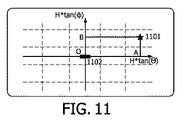
当業者にとって、ターゲット領域と光源間の位置関係を計算するやり方を理解することは容易である。例えば、3D空間において、ターゲット領域1001と光源1002間の位置関係は、地面の点Oと点A間の距離(「距離OA」とも呼ばれる)、地面の点Oと点B間の距離(「距離OB」とも呼ばれる)を含むことができる。距離を計算するための例示的な実施形態は、図11を参照することができ、ここでは、本発明の例示的な実施形態によるターゲット領域1101と光源1102間の位置関係を示す概略図が示されている。距離OAは、H・tan(θ)によって計算することができて、距離OBは、H・tan(φ)によって計算され得る。
For those skilled in the art, it is easy to understand how to calculate the positional relationship between the target area and the light source. For example, in the 3D space, the positional relationship between the
上記を考慮して、ターゲット領域の(「E」として表示される)照度は、次式 Considering the above, the illuminance (displayed as “E”) of the target area is
図12を次に参照すると、本発明の例示的な実施形態による照明システムにおいてターゲット領域の照度を制御するための装置1200を示す概略図が示されている。照明システムは、図1に示すような照明システム100であってもよく、この照明システムは、少なくとも1つの光源を備え、少なくとも1つの光源それぞれが複数の光モジュールを備え、複数の光モジュールそれぞれが独立に調整可能である。
Referring now to FIG. 12, a schematic diagram illustrating an
装置1200は、2つの構成要素である、セレクタ1210およびアジャスタ1220を備えることができる。本発明の実施形態において、セレクタ1210は、少なくとも1つの光源とターゲット領域間の位置関係および少なくとも1つの光源の照明分布に基づいて、少なくとも1つの光源から、その領域の照度に関連付けられる少なくとも1つの光モジュールを選択するように構成されてもよく、アジャスタ1220は、選択された少なくとも1つの光モジュールのうちの少なくとも1つを調整するように構成されてもよい。
The
本発明の実施形態において、セレクタ1210は、少なくとも1つの光源からのターゲット領域の少なくとも1つの相対的な方向を計算するように構成された計算ユニット、および少なくとも1つの相対的な方向に基づいて、少なくとも1つの光源とターゲット領域間の位置関係を得るように構成された第1の取得ユニットを備えることができる。
In an embodiment of the present invention, the
本発明の実施形態において、セレクタ1210は、位置関係から、光源からのターゲット領域の相対的な方向を得るように構成された第2の取得ユニットと、光源の照明分布から、光源から放射する複数の光モジュールの照明方向を得るように構成された第3の取得ユニットと、相対的な方向を照明方向と比較するように構成された比較ユニットと、比較結果に基づいて、光源の複数の光モジュールから1つの光モジュールを選択するように構成された選択ユニットとを備えることができる。
In the embodiment of the present invention, the
本発明の実施形態において、アジャスタ1220は、照明要件を満たすように少なくとも1つの光モジュールを調和してまたは独立に調整するように構成された第1の調整ユニットを備えることができる。
In embodiments of the present invention, the
本発明の実施形態において、光源の照明分布は、三角形、小滴、または扇形の形態であってもよい。 In an embodiment of the present invention, the illumination distribution of the light source may be in the form of a triangle, a droplet, or a fan.
本発明の実施形態において、光モジュールは、少なくとも1つの発光素子を備えることができる。本発明の実施形態において、発光素子は、LED、OLED、または蛍光灯であってもよい。 In the embodiment of the present invention, the optical module may include at least one light emitting element. In the embodiment of the present invention, the light emitting element may be an LED, an OLED, or a fluorescent lamp.
図2および3を参照して説明したように、装置1200は、機能性を実施するように構成され得ることに留意されたい。したがって、本発明の方法、例えば、方法200および300に関して論じた特徴は、装置1200の対応する構成要素に適用される。装置1200の構成要素は、ハードウェア、ソフトウェア、ファームウェア、および/または、それらの任意の組み合わせにおいて具現化されてもよいことにさらに留意されたい。例えば、装置1200の構成要素は、それぞれ回路、プロセッサ、または任意の他の適切なデバイスによって実施されてもよい。当業者は、上記の例が単に例示の目的のためであって、限定としてではないことを理解されるであろう。
Note that as described with reference to FIGS. 2 and 3,
本開示の一部の実施形態において、装置1200は、少なくとも1つのプロセッサを備える。本開示の実施形態での使用に適した少なくとも1つのプロセッサは、一例を挙げると、既知または将来開発される汎用のプロセッサおよび特殊用途のプロセッサの両方を含んでもよい。装置1200は、少なくとも1つのメモリをさらに含む。少なくとも1つのメモリは、例えば、半導体メモリデバイス、例えば、RAM、ROM、EPROM、EEPROM、および、フラッシュメモリデバイスを含んでもよい。少なくとも1つのメモリは、コンピュータ実行可能命令のプログラムを保存するために使用されてもよい。プログラムは、任意の高レベルおよび/または低レベルのコンパイル可能なもしくは解釈可能なプログラミング言語で書くことができる。実施形態によると、コンピュータ実行可能命令は、少なくとも1つのプロセッサを用いて、本発明の方法、例えば上で論じたような方法200または300に従って、装置1200に少なくとも行わせるように構成されてもよい。
In some embodiments of the present disclosure, the
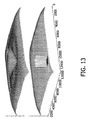
図13を次に参照すると、本発明の例示的な実施形態による例示的な照度の結果および所望の照度の結果を示す概略図が示されている。 Referring now to FIG. 13, a schematic diagram illustrating exemplary illumination results and desired illumination results according to an exemplary embodiment of the present invention is shown.
図13に示すように、下部はターゲット領域に対する所望の照度分布を示し、上部は、本発明により得られたターゲット領域に対する照度分布を示す。所望の照度分布は、他の場所の照度をもとのままに維持しながら、照明が低下して、ターゲット領域がより暗くなるように、ターゲット領域の照度を低減させることができる。本発明の解決策により、ターゲット領域の照度が首尾よく低減され、他の領域の照度を実質的にもとのままに維持していることがわかる。 As shown in FIG. 13, the lower part shows a desired illuminance distribution for the target area, and the upper part shows the illuminance distribution for the target area obtained by the present invention. The desired illuminance distribution can reduce the illuminance of the target area so that the illumination is reduced and the target area becomes darker while maintaining the illuminance of other places unchanged. It can be seen that the solution of the present invention successfully reduces the illuminance of the target area and maintains the illuminance of other areas substantially intact.
本発明の実施形態において、コンピュータで読取り可能な媒体上で具体的に具現化されるコンピュータ・プログラムを備えるコンピュータ・プログラム製品が提供される。コンピュータ・プログラムは、本発明による方法を実行するように構成され得る。例えば、コンピュータ・プログラムは、少なくとも1つの光源とターゲット領域間の位置関係、および少なくとも1つの光源それぞれの照明分布に基づいて、1つの光源から、その場所の照度に関連付けられている少なくとも1つの光モジュールを選択するための命令と、選択された少なくとも1つの光モジュールのうちの少なくとも1つを調整するための命令とを備えることができる。 In an embodiment of the present invention, a computer program product comprising a computer program specifically embodied on a computer readable medium is provided. A computer program may be configured to carry out the method according to the invention. For example, the computer program can generate at least one light associated with the illuminance at the location from one light source based on the positional relationship between the at least one light source and the target area and the illumination distribution of each of the at least one light source. Instructions for selecting a module and instructions for adjusting at least one of the selected at least one optical module may be provided.
上記の説明を通して、当業者は、本発明の実施形態が、オープン領域に対する個人専用の照明を実現するために、照明システムにおいてターゲット領域の照度を制御するための有効なメカニズムを提供することを容易に理解されるであろう。照明システム(例えば、図1に示すようなシステム100)は、少なくとも1つの光源を備えることができ、少なくとも1つの光源それぞれが複数の光モジュールを備え、複数の光モジュールのそれぞれが独立に調整可能である。照明システムは、本発明による装置を備えることができるコントローラをさらに備えてもよい。この構成を使用することによって、周囲の同僚の働き心地を乱さずに、ユーザの作業領域の照度を彼もしくは彼女の好み及び活動に合わせる、または個人専用にすることが可能である。したがって、ターゲット領域の照度に関するユーザ体験は、著しく、効果的に改善され得る。
Through the above description, those skilled in the art will readily understand that embodiments of the present invention provide an effective mechanism for controlling the illuminance of a target area in a lighting system in order to achieve personalized lighting for an open area. Will be understood. An illumination system (eg,
全体に、様々な例示的な実施形態は、ハードウェアまたは特殊用途の回路、ソフトウェア、論理回路またはそれらの任意の組み合わせにおいて実施されてもよい。例えば、一部の態様は、ハードウェアにおいて実施されてもよく、他の態様は、コントローラ、マイクロプロセッサまたは他のコンピューティングデバイスによって実行され得るファームウェアまたはソフトウェアにおいて実施されてもよいが、本発明は、それらに限定されない。本発明の例示的な実施形態の様々な態様が、ブロック図、流れ図、または他のなんらかの図的表現を使用することによって示される場合があるが、本明細書で説明したこれらのブロック、装置、システム、技法または方法は、非限定的な例として、ハードウェア、ソフトウェア、ファームウェア、特殊用途の回路もしくは論理回路、多目的のハードウェアもしくはコントローラ、または他のコンピューティングデバイス、あるいはそれらの組み合わせにおいて実施されてもよいことがよくわかる。 Overall, the various exemplary embodiments may be implemented in hardware or special purpose circuits, software, logic circuits or any combination thereof. For example, some aspects may be implemented in hardware and other aspects may be implemented in firmware or software, which may be executed by a controller, microprocessor, or other computing device. , But not limited to them. While various aspects of exemplary embodiments of the invention may be illustrated using block diagrams, flowcharts, or some other graphical representation, these blocks, devices, described herein, The system, technique or method is implemented in hardware, software, firmware, special purpose circuits or logic circuits, general purpose hardware or controllers, or other computing devices, or combinations thereof, as non-limiting examples. You can see that it is okay.
具体的には、図2および3に示す様々なブロックは、方法のステップとして、および/または、コンピュータ・プログラム・コードの動作によって生じる動作として、および/または、関連付けられた機能(複数可)を実行するように構築された複数の結合論理回路素子として、見なすこともできる。本発明の例示的な実施形態の少なくとも一部の態様は、集積回路チップおよびモジュールなどの様々な構成要素において実行されてもよく、本発明の例示的な実施形態は、本発明の例示的な実施形態により動作するように構成可能な集積回路、FPGAまたはASICとして具現化される装置において実現されてもよい。 Specifically, the various blocks shown in FIGS. 2 and 3 may be performed as method steps and / or operations caused by the operation of computer program code and / or associated function (s). It can also be viewed as a plurality of coupled logic elements that are constructed to perform. At least some aspects of the exemplary embodiments of the invention may be implemented in various components such as integrated circuit chips and modules, and the exemplary embodiments of the invention are illustrative of the invention. It may be implemented in an apparatus embodied as an integrated circuit, FPGA or ASIC that can be configured to operate according to an embodiment.
上記の議論にはいくつかの具体的な実施態様の詳細が含まれているが、これらは、いずれの発明、または特許請求され得るものの範囲に対する限定としてではなく、特定の発明の特定の実施形態に特有となりうる特徴の説明として解釈されるべきである。また、別の実施形態のコンテクストにおいて本明細書に記載されたある特徴は、単一の実施形態において組み合わせて実施されてもよい。逆に、単一の実施形態のコンテクストにおいて記載された様々な特徴も、複数の実施形態において別々に、または任意の適切なサブ組み合わせにおいて実施されてもよい。さらに、特徴がある組み合わせにおいて作用するとして上で記載され、そのように最初に特許請求されることさえあるが、特許請求される組み合わせからの1つまたは複数の特徴は、ある場合にはその組み合わせから削除されてもよく、特許請求される組み合わせは、サブ組み合わせまたはサブ組み合わせの変形形態を対象としてもよい。 Although the above discussion includes details of several specific embodiments, these are not intended as limitations on the scope of any invention or what may be claimed, but specific embodiments of a particular invention. Should be construed as an explanation of features that may be specific to Certain features that are described in this specification in the context of another embodiment may also be implemented in combination in a single embodiment. Conversely, various features that are described in the context of a single embodiment may also be implemented in multiple embodiments separately or in any suitable subcombination. Further, although one or more features from a claimed combination are described in the above as acting in one combination, and even so initially claimed, in some cases the combination And claimed combinations may be directed to sub-combinations or variations of sub-combinations.
同様に、動作は、図面において特定の順番で示されているが、これは、そうした動作が図示された特定の順番でもしくは順序で行われるべきであるということ、または図示された動作がすべて望ましい結果を実現するために行われるべきであるということを要求しているとして理解されるべきではない。ある状況では、マルチタスクおよび並列処理が有利な場合がある。さらに、上記の実施形態における様々なシステム構成要素の分離は、すべての実施形態においてそうした分離を要求していると理解されるべきではなく、記載されたプログラム構成要素およびシステムは、概して互いに単一のソフトウェア製品に統合されてもよく、または複数のソフトウェア製品にパッケージ化されてもよいことを理解されたい。 Similarly, operations are shown in a particular order in the drawings, which means that such operations should be performed in the particular order or sequence shown, or all the operations shown are desirable. It should not be understood as requiring that it be done to achieve a result. In certain situations, multitasking and parallel processing may be advantageous. Furthermore, the separation of various system components in the above embodiments should not be construed as requiring such separation in all embodiments, and the described program components and systems are generally single from each other. It should be understood that it may be integrated into a software product or packaged into multiple software products.
本発明の上記の例示的な実施形態に対する様々な変更形態、適合形態は、上記の説明を考慮して添付図面とともに読むとき、関連する当技術分野の当業者には明らかになる可能性がある。すべての変更形態は、それでもなお本発明の非限定的で例示的な実施形態の範囲内にある。さらに、本明細書で述べた本発明の他の実施形態は、上記の説明および関連付けられた図面において提示された教示の利点を有する本発明のこれらの実施形態が関係する当業者には思い浮かぶであろう。 Various modifications and adaptations to the above exemplary embodiments of the present invention may become apparent to those skilled in the relevant art when read in conjunction with the accompanying drawings in view of the above description. . All modifications are still within the scope of the non-limiting exemplary embodiments of the present invention. Furthermore, other embodiments of the invention described herein will occur to those skilled in the art to which these embodiments of the invention pertain to have the advantages of the teachings presented in the foregoing description and the associated drawings. Will.
したがって、本発明の実施形態は、開示された特定の実施形態およびその変更形態に限定されるべきではなく、他の実施形態は、添付の特許請求の範囲の範囲内に含まれることが意図されていることを理解されるべきである。本明細書において特定の用語が使用されているが、それらは限定する目的ではなく、単に一般的、解説的な意味において使用されている。 Therefore, embodiments of the invention should not be limited to the specific embodiments disclosed and variations thereof, but other embodiments are intended to be included within the scope of the appended claims. Should be understood. Although specific terms are used herein, they are not intended to be limiting but merely used in a general and explanatory sense.
Claims (11)
前記照明システムは少なくとも1つの光源を備え、前記少なくとも1つの光源それぞれは複数の光モジュールを備え、前記複数の光モジュールそれぞれは独立に照度について調整可能であり、
前記方法は、
前記少なくとも1つの光源と前記ターゲット領域との間の位置関係を取得するステップと
前記位置関係から、前記少なくとも1つの光源からの前記ターゲット領域の相対的な方向を取得するステップと、
前記少なくとも1つの光源の照明分布から、前記少なくとも1つの光源から放射する複数の光モジュールの照明方向を得るステップと、
前記相対的な方向と前記照明方向とを比較するステップと、
前記比較の結果に基づいて、前記少なくとも1つの光源の前記複数の光モジュールから少なくとも1つの光モジュールを選択するステップと
選択された前記少なくとも1つの光モジュールのうちの少なくとも1つを照度について調整するステップと、
を含む、方法。 A method for controlling the illuminance of a target area in a lighting system, comprising:
The illumination system includes at least one light source, each of the at least one light source includes a plurality of light modules, and each of the plurality of light modules is independently adjustable for illuminance ,
The method
Obtaining a positional relationship between the at least one light source and the target region;
Obtaining a relative direction of the target area from the at least one light source from the positional relationship;
Obtaining an illumination direction of a plurality of optical modules radiating from the at least one light source from an illumination distribution of the at least one light source;
Comparing the relative direction and the illumination direction;
Based on the result of the comparison, selecting at least one light module from the plurality of light modules of the at least one light source and adjusting at least one of the selected at least one light module for illuminance Steps,
Including a method.
照明要件を満たすように前記少なくとも1つの光モジュールを調和してまたは独立に照度について調整するステップを含む、請求項1に記載の方法。 Adjusting at least one of the selected at least one light module for illuminance ,
The method of claim 1, comprising adjusting the at least one light module for illumination in a coordinated or independent manner to meet lighting requirements.
請求項1に記載の方法。 The illumination distribution of the at least one light source is in the form of a triangle, a droplet, or a fan;
The method of claim 1.
前記少なくとも1つの発光素子は、発光ダイオード(LED)、有機発光ダイオード(OLED)、または、蛍光灯である、
請求項1に記載の方法。 The optical module includes at least one light emitting element,
The at least one light emitting element is a light emitting diode (LED), an organic light emitting diode (OLED), or a fluorescent lamp.
The method of claim 1.
前記照明システムは少なくとも1つの光源を備え、前記少なくとも1つの光源それぞれは複数の光モジュールを備え、前記複数の光モジュールそれぞれは独立に照度について調整可能であり、
前記装置は、
前記少なくとも1つの光源と前記ターゲット領域との間の位置関係を取得する第1の取得ユニットと、
前記位置関係から、前記少なくとも1つの光源からの前記ターゲット領域の相対的な方向を取得する第2の取得ユニットと、
前記少なくとも1つの光源の照明分布から、前記少なくとも1つの光源から放射する複数の光モジュールの照明方向を取得する第3の取得ユニットと、
前記相対的な方向と前記照明方向とを比較する比較ユニットと、
前記比較の結果に基づいて、前記少なくとも1つの光源の前記複数の光モジュールから少なくとも1つの光モジュールを選択する選択ユニットと、を有するセレクタと、
選択された前記少なくとも1つの光モジュールのうちの少なくとも1つを照度について調整するアジャスタと、
を備える、装置。 An apparatus for controlling the illuminance of a target area in an illumination system,
The illumination system includes at least one light source, each of the at least one light source includes a plurality of light modules, and each of the plurality of light modules is independently adjustable for illuminance ,
The device is
A first acquisition unit for acquiring a positional relationship between the at least one light source and the target region;
A second acquisition unit for acquiring a relative direction of the target area from the at least one light source from the positional relationship;
A third acquisition unit for acquiring illumination directions of a plurality of optical modules radiating from the at least one light source from the illumination distribution of the at least one light source;
A comparison unit for comparing the relative direction and the illumination direction;
A selector having a selection unit that selects at least one optical module from the plurality of optical modules of the at least one light source based on the result of the comparison;
An adjuster for adjusting at least one of the selected at least one light module for illumination ;
An apparatus comprising:
照明要件を満たすように前記少なくとも1つの光モジュールを調和してまたは独立に照度について調整するように構成された第1の調整ユニット、
を備える、請求項5に記載の装置。 The adjuster is
A first adjustment unit configured to harmoniously or independently adjust the illuminance to meet the lighting requirements;
The apparatus of claim 5 , comprising:
請求項5に記載の装置。 The illumination distribution of the at least one light source is in the form of a triangle, a droplet, or a fan;
The apparatus according to claim 5 .
前記少なくとも1つの発光素子は、発光ダイオード(LED)、有機発光ダイオード(OLED)、または、蛍光灯である、
請求項5に記載の装置。 The optical module includes at least one light emitting element,
The at least one light emitting element is a light emitting diode (LED), an organic light emitting diode (OLED), or a fluorescent lamp.
The apparatus according to claim 5 .
前記照明システムは少なくとも1つの光源を備え、前記少なくとも1つの光源それぞれは複数の光モジュールを備え、前記複数の光モジュールそれぞれは独立に照度について調整可能であり、
請求項5から8のいずれか1項に記載の装置を備える、コントローラ。 A controller for controlling the illuminance of a target area in a lighting system,
The illumination system includes at least one light source, each of the at least one light source includes a plurality of light modules, and each of the plurality of light modules is independently adjustable for illuminance ,
A controller comprising the apparatus according to claim 5 .
コンピュータ・プログラム。 A computer program embodied on a computer readable medium, configured to perform the method of any one of claims 1 to 4 .
Computer program.
少なくとも1つの光源を備え、前記少なくとも1つの光源それぞれは複数の光モジュールを備え、前記複数の光モジュールそれぞれは独立に照度について調整可能であり、
前記照明システムにおいてターゲット領域の照度を制御するように構成されたコントローラを備え、前記コントローラは請求項5から8のいずれか1項に記載の装置を含む、
照明システム。
A lighting system,
Comprising at least one light source, each of the at least one light source comprising a plurality of light modules, each of the plurality of light modules being independently adjustable for illuminance ,
A controller configured to control illuminance of a target area in the illumination system, the controller comprising the apparatus of any one of claims 5 to 8 .
Lighting system.
Applications Claiming Priority (3)
| Application Number | Priority Date | Filing Date | Title |
|---|---|---|---|
| CN2011085196 | 2011-12-31 | ||
| CNPCT/CN2011/085196 | 2011-12-31 | ||
| PCT/IB2012/057663 WO2013098759A1 (en) | 2011-12-31 | 2012-12-22 | Personalized lighting for open area |
Publications (2)
| Publication Number | Publication Date |
|---|---|
| JP2015506548A JP2015506548A (en) | 2015-03-02 |
| JP6207525B2 true JP6207525B2 (en) | 2017-10-04 |
Family
ID=47749897
Family Applications (1)
| Application Number | Title | Priority Date | Filing Date |
|---|---|---|---|
| JP2014549604A Active JP6207525B2 (en) | 2011-12-31 | 2012-12-22 | Private lighting for open areas |
Country Status (5)
| Country | Link |
|---|---|
| US (1) | US9426865B2 (en) |
| EP (1) | EP2752095B1 (en) |
| JP (1) | JP6207525B2 (en) |
| RU (1) | RU2631335C2 (en) |
| WO (1) | WO2013098759A1 (en) |
Families Citing this family (11)
| Publication number | Priority date | Publication date | Assignee | Title |
|---|---|---|---|---|
| BR112015004595A2 (en) | 2012-08-28 | 2017-07-04 | Delos Living Llc | systems, methods and articles to improve the well-being associated with living environments |
| TWI508627B (en) * | 2013-03-22 | 2015-11-11 | Internat Mobile Iot Corp | Illumination control system |
| US9801260B2 (en) * | 2013-09-20 | 2017-10-24 | Osram Sylvania Inc. | Techniques and graphical user interface for controlling solid-state luminaire with electronically adjustable light beam distribution |
| US10568179B2 (en) * | 2013-09-20 | 2020-02-18 | Osram Sylvania Inc. | Techniques and photographical user interface for controlling solid-state luminaire with electronically adjustable light beam distribution |
| US10712722B2 (en) | 2014-02-28 | 2020-07-14 | Delos Living Llc | Systems and articles for enhancing wellness associated with habitable environments |
| US9380684B2 (en) | 2014-04-14 | 2016-06-28 | GE Lighting Solutions, LLC | Method and system for an electronically adaptive photometry for roadway lighting |
| US11668481B2 (en) | 2017-08-30 | 2023-06-06 | Delos Living Llc | Systems, methods and articles for assessing and/or improving health and well-being |
| US11649977B2 (en) | 2018-09-14 | 2023-05-16 | Delos Living Llc | Systems and methods for air remediation |
| US11844163B2 (en) | 2019-02-26 | 2023-12-12 | Delos Living Llc | Method and apparatus for lighting in an office environment |
| US11898898B2 (en) | 2019-03-25 | 2024-02-13 | Delos Living Llc | Systems and methods for acoustic monitoring |
| CN113677057B (en) * | 2021-02-09 | 2024-02-23 | 天津九安医疗电子股份有限公司 | Method and system for rapidly and quantitatively adjusting beam angle of lighting device |
Family Cites Families (24)
| Publication number | Priority date | Publication date | Assignee | Title |
|---|---|---|---|---|
| JPH05120904A (en) * | 1991-10-25 | 1993-05-18 | Nissan Motor Co Ltd | Road lighting device |
| AU2001281757A1 (en) | 2000-08-23 | 2002-03-04 | Ot Light Aps | Method and system for controlling the direction, and preferably also the intensity, of light at a site and use of such system |
| FI109430B (en) * | 2000-12-21 | 2002-07-31 | Mauri Kalevi Drufva | Lighting method and device |
| CN1714606A (en) * | 2002-11-22 | 2005-12-28 | 皇家飞利浦电子股份有限公司 | System for and method of controlling a light source and lighting arrangement |
| DE10338535A1 (en) | 2003-08-19 | 2005-08-04 | Prc Krochmann Gmbh | Daylight sensor system for artificial light control and light intensity distribution in interiors has sensor units in individual housings having adjustable direction |
| JP4374473B2 (en) | 2003-12-24 | 2009-12-02 | 学校法人同志社 | Control system and lighting control system |
| JP2007018773A (en) * | 2005-07-05 | 2007-01-25 | Toshiba Corp | Illumination control device, illumination system and method |
| US7775678B2 (en) * | 2005-09-26 | 2010-08-17 | Koninklijke Philips Electronics N.V. | Method and device for grouping at least three lamps |
| ES2272180B1 (en) * | 2005-09-29 | 2008-04-01 | Universitat Politecnica De Catalunya | LIGHTING SYSTEM, INSTALLATION FOR A SURGICAL INTERVENTION, AND LIGHTING METHOD OF A TABLE OF OPERATIONS IN A CHIROPHANE. |
| RU2413475C2 (en) * | 2006-01-24 | 2011-03-10 | Закрытое акционерное общество "Завод "ЭМА" | Surgical light with controlled optical radiation |
| US7712926B2 (en) * | 2006-08-17 | 2010-05-11 | Koninklijke Philips Electronics N.V. | Luminaire comprising adjustable light modules |
| JP2008251337A (en) | 2007-03-30 | 2008-10-16 | Doshisha | Lighting system |
| TWI357285B (en) | 2007-09-13 | 2012-01-21 | Ind Tech Res Inst | Automatic lighting control system and method |
| US8742686B2 (en) | 2007-09-24 | 2014-06-03 | Integrated Illumination Systems, Inc. | Systems and methods for providing an OEM level networked lighting system |
| JP4726883B2 (en) * | 2007-11-16 | 2011-07-20 | トヨタ自動車株式会社 | Vehicle headlamp |
| US10539311B2 (en) * | 2008-04-14 | 2020-01-21 | Digital Lumens Incorporated | Sensor-based lighting methods, apparatus, and systems |
| US20100114340A1 (en) | 2008-06-02 | 2010-05-06 | Charles Huizenga | Automatic provisioning of wireless control systems |
| JP5086926B2 (en) * | 2008-07-15 | 2012-11-28 | キヤノン株式会社 | Calculation method, program, and exposure method |
| JP5230371B2 (en) * | 2008-11-21 | 2013-07-10 | パナソニック株式会社 | Lighting system |
| WO2010070517A1 (en) * | 2008-12-15 | 2010-06-24 | Philips Intellectual Property & Standards Gmbh | System for simulation of a lighting distribution |
| JP2012514829A (en) | 2009-01-07 | 2012-06-28 | コーニンクレッカ フィリップス エレクトロニクス エヌ ヴィ | Intelligent controllable lighting network and schema therefor |
| TWI398745B (en) * | 2009-03-06 | 2013-06-11 | Ind Tech Res Inst | Positioning mehtod and positioning system based on light intensity |
| JP2010272441A (en) * | 2009-05-25 | 2010-12-02 | Panasonic Electric Works Co Ltd | Lighting system |
| RU2012114864A (en) | 2009-09-15 | 2013-10-27 | Конинклейке Филипс Электроникс Н.В. | METHOD FOR LIGHT DISTRIBUTION MANAGEMENT IN A SPACE INCLUDING MULTIPLE INSTALLED LIGHT SOURCES AND AN EXTERNAL LIGHT SOURCE |
-
2012
- 2012-12-22 EP EP12826631.9A patent/EP2752095B1/en active Active
- 2012-12-22 US US14/368,939 patent/US9426865B2/en active Active
- 2012-12-22 WO PCT/IB2012/057663 patent/WO2013098759A1/en active Application Filing
- 2012-12-22 RU RU2014131722A patent/RU2631335C2/en active
- 2012-12-22 JP JP2014549604A patent/JP6207525B2/en active Active
Also Published As
| Publication number | Publication date |
|---|---|
| US9426865B2 (en) | 2016-08-23 |
| RU2631335C2 (en) | 2017-09-21 |
| JP2015506548A (en) | 2015-03-02 |
| WO2013098759A1 (en) | 2013-07-04 |
| EP2752095B1 (en) | 2018-03-07 |
| RU2014131722A (en) | 2016-02-20 |
| US20140375230A1 (en) | 2014-12-25 |
| EP2752095A1 (en) | 2014-07-09 |
Similar Documents
| Publication | Publication Date | Title |
|---|---|---|
| JP6207525B2 (en) | Private lighting for open areas | |
| JP6360155B2 (en) | Lighting system and method for providing active glare control | |
| JP6669781B2 (en) | Wireless lighting control system | |
| US20160088707A1 (en) | Methods and apparatus for controlling lighting based on user manipulation of a mobile computing device | |
| JP2016520968A5 (en) | ||
| US9091417B2 (en) | Lighting apparatus with reflector and outer lens | |
| TW201531164A (en) | Dynamic spatially-resolved lighting using composited lighting models | |
| JP6107474B2 (en) | Lighting system | |
| JP6223348B2 (en) | Distance estimation using split beam luminaires | |
| JP6872648B2 (en) | Lighting units and related methods that provide reduced intensity light output based on user proximity | |
| JP2016504745A5 (en) | ||
| EP2620695A3 (en) | Vehicular headlamp | |
| CN109644532B (en) | Light output positioning | |
| US10681783B2 (en) | Luminaire with programmable light distribution | |
| US20180173941A1 (en) | Light irradiation method and light irradiation apparatus | |
| RU2017135374A (en) | METHOD AND SYSTEM OF ZONE LIGHTING | |
| JP2011154830A (en) | Illumination system with variable arrangement position | |
| JP2019102306A (en) | Lighting apparatus | |
| CN104012180A (en) | Personalized Lighting For Open Area | |
| JP6992454B2 (en) | Lighting system | |
| CN107850764B (en) | Forward stroke asymmetric optics design | |
| US10656813B1 (en) | Light control for an image platform | |
| JP2020167112A (en) | Lighting system | |
| JP2020167109A (en) | Lighting system | |
| JP6994609B1 (en) | Control module for controlling luminaires |
Legal Events
| Date | Code | Title | Description |
|---|---|---|---|
| RD02 | Notification of acceptance of power of attorney |
Free format text: JAPANESE INTERMEDIATE CODE: A7422 Effective date: 20150612 |
|
| A621 | Written request for application examination |
Free format text: JAPANESE INTERMEDIATE CODE: A621 Effective date: 20151217 |
|
| A711 | Notification of change in applicant |
Free format text: JAPANESE INTERMEDIATE CODE: A711 Effective date: 20160927 |
|
| A977 | Report on retrieval |
Free format text: JAPANESE INTERMEDIATE CODE: A971007 Effective date: 20161026 |
|
| A131 | Notification of reasons for refusal |
Free format text: JAPANESE INTERMEDIATE CODE: A131 Effective date: 20161109 |
|
| A601 | Written request for extension of time |
Free format text: JAPANESE INTERMEDIATE CODE: A601 Effective date: 20170201 |
|
| A521 | Request for written amendment filed |
Free format text: JAPANESE INTERMEDIATE CODE: A523 Effective date: 20170508 |
|
| TRDD | Decision of grant or rejection written | ||
| A01 | Written decision to grant a patent or to grant a registration (utility model) |
Free format text: JAPANESE INTERMEDIATE CODE: A01 Effective date: 20170807 |
|
| A61 | First payment of annual fees (during grant procedure) |
Free format text: JAPANESE INTERMEDIATE CODE: A61 Effective date: 20170905 |
|
| R150 | Certificate of patent or registration of utility model |
Ref document number: 6207525 Country of ref document: JP Free format text: JAPANESE INTERMEDIATE CODE: R150 |
|
| S531 | Written request for registration of change of domicile |
Free format text: JAPANESE INTERMEDIATE CODE: R313531 |
|
| S533 | Written request for registration of change of name |
Free format text: JAPANESE INTERMEDIATE CODE: R313533 |
|
| R350 | Written notification of registration of transfer |
Free format text: JAPANESE INTERMEDIATE CODE: R350 |
|
| R250 | Receipt of annual fees |
Free format text: JAPANESE INTERMEDIATE CODE: R250 |
|
| R250 | Receipt of annual fees |
Free format text: JAPANESE INTERMEDIATE CODE: R250 |
|
| R250 | Receipt of annual fees |
Free format text: JAPANESE INTERMEDIATE CODE: R250 |