JP6185945B2 - SOC display device for hybrid vehicle - Google Patents
SOC display device for hybrid vehicle Download PDFInfo
- Publication number
- JP6185945B2 JP6185945B2 JP2015032488A JP2015032488A JP6185945B2 JP 6185945 B2 JP6185945 B2 JP 6185945B2 JP 2015032488 A JP2015032488 A JP 2015032488A JP 2015032488 A JP2015032488 A JP 2015032488A JP 6185945 B2 JP6185945 B2 JP 6185945B2
- Authority
- JP
- Japan
- Prior art keywords
- soc
- mode
- display
- travel mode
- range
- Prior art date
- Legal status (The legal status is an assumption and is not a legal conclusion. Google has not performed a legal analysis and makes no representation as to the accuracy of the status listed.)
- Active
Links
- 230000007423 decrease Effects 0.000 claims description 24
- 238000007599 discharging Methods 0.000 claims description 7
- 230000008859 change Effects 0.000 description 16
- 230000005540 biological transmission Effects 0.000 description 15
- 230000001172 regenerating effect Effects 0.000 description 14
- 230000007704 transition Effects 0.000 description 12
- 238000010248 power generation Methods 0.000 description 11
- 238000012546 transfer Methods 0.000 description 10
- 238000010586 diagram Methods 0.000 description 9
- 230000007246 mechanism Effects 0.000 description 4
- 238000002485 combustion reaction Methods 0.000 description 3
- HBBGRARXTFLTSG-UHFFFAOYSA-N Lithium ion Chemical compound [Li+] HBBGRARXTFLTSG-UHFFFAOYSA-N 0.000 description 2
- 241000156302 Porcine hemagglutinating encephalomyelitis virus Species 0.000 description 2
- 229910001416 lithium ion Inorganic materials 0.000 description 2
- 229910052987 metal hydride Inorganic materials 0.000 description 2
- 230000004048 modification Effects 0.000 description 2
- 238000012986 modification Methods 0.000 description 2
- 229910052759 nickel Inorganic materials 0.000 description 2
- PXHVJJICTQNCMI-UHFFFAOYSA-N nickel Substances [Ni] PXHVJJICTQNCMI-UHFFFAOYSA-N 0.000 description 2
- -1 nickel metal hydride Chemical class 0.000 description 2
- 238000012545 processing Methods 0.000 description 2
- 230000009467 reduction Effects 0.000 description 2
- 230000004044 response Effects 0.000 description 2
- 238000013459 approach Methods 0.000 description 1
- 239000003086 colorant Substances 0.000 description 1
- 238000009500 colour coating Methods 0.000 description 1
- 238000004891 communication Methods 0.000 description 1
- 238000007796 conventional method Methods 0.000 description 1
- 230000008878 coupling Effects 0.000 description 1
- 238000010168 coupling process Methods 0.000 description 1
- 238000005859 coupling reaction Methods 0.000 description 1
- 230000003247 decreasing effect Effects 0.000 description 1
- 238000001514 detection method Methods 0.000 description 1
- 239000012530 fluid Substances 0.000 description 1
- 239000000446 fuel Substances 0.000 description 1
- 230000010365 information processing Effects 0.000 description 1
- 230000010354 integration Effects 0.000 description 1
- 238000000034 method Methods 0.000 description 1
- 238000010422 painting Methods 0.000 description 1
- 230000008569 process Effects 0.000 description 1
- 238000011084 recovery Methods 0.000 description 1
- 230000008929 regeneration Effects 0.000 description 1
- 238000011069 regeneration method Methods 0.000 description 1
- 230000001360 synchronised effect Effects 0.000 description 1
- XLYOFNOQVPJJNP-UHFFFAOYSA-N water Substances O XLYOFNOQVPJJNP-UHFFFAOYSA-N 0.000 description 1
Images


Classifications
-
- B—PERFORMING OPERATIONS; TRANSPORTING
- B60—VEHICLES IN GENERAL
- B60W—CONJOINT CONTROL OF VEHICLE SUB-UNITS OF DIFFERENT TYPE OR DIFFERENT FUNCTION; CONTROL SYSTEMS SPECIALLY ADAPTED FOR HYBRID VEHICLES; ROAD VEHICLE DRIVE CONTROL SYSTEMS FOR PURPOSES NOT RELATED TO THE CONTROL OF A PARTICULAR SUB-UNIT
- B60W20/00—Control systems specially adapted for hybrid vehicles
- B60W20/10—Controlling the power contribution of each of the prime movers to meet required power demand
- B60W20/13—Controlling the power contribution of each of the prime movers to meet required power demand in order to stay within battery power input or output limits; in order to prevent overcharging or battery depletion
-
- B—PERFORMING OPERATIONS; TRANSPORTING
- B60—VEHICLES IN GENERAL
- B60K—ARRANGEMENT OR MOUNTING OF PROPULSION UNITS OR OF TRANSMISSIONS IN VEHICLES; ARRANGEMENT OR MOUNTING OF PLURAL DIVERSE PRIME-MOVERS IN VEHICLES; AUXILIARY DRIVES FOR VEHICLES; INSTRUMENTATION OR DASHBOARDS FOR VEHICLES; ARRANGEMENTS IN CONNECTION WITH COOLING, AIR INTAKE, GAS EXHAUST OR FUEL SUPPLY OF PROPULSION UNITS IN VEHICLES
- B60K35/00—Instruments specially adapted for vehicles; Arrangement of instruments in or on vehicles
- B60K35/20—Output arrangements, i.e. from vehicle to user, associated with vehicle functions or specially adapted therefor
- B60K35/28—Output arrangements, i.e. from vehicle to user, associated with vehicle functions or specially adapted therefor characterised by the type of the output information, e.g. video entertainment or vehicle dynamics information; characterised by the purpose of the output information, e.g. for attracting the attention of the driver
-
- B—PERFORMING OPERATIONS; TRANSPORTING
- B60—VEHICLES IN GENERAL
- B60K—ARRANGEMENT OR MOUNTING OF PROPULSION UNITS OR OF TRANSMISSIONS IN VEHICLES; ARRANGEMENT OR MOUNTING OF PLURAL DIVERSE PRIME-MOVERS IN VEHICLES; AUXILIARY DRIVES FOR VEHICLES; INSTRUMENTATION OR DASHBOARDS FOR VEHICLES; ARRANGEMENTS IN CONNECTION WITH COOLING, AIR INTAKE, GAS EXHAUST OR FUEL SUPPLY OF PROPULSION UNITS IN VEHICLES
- B60K35/00—Instruments specially adapted for vehicles; Arrangement of instruments in or on vehicles
- B60K35/60—Instruments characterised by their location or relative disposition in or on vehicles
-
- B—PERFORMING OPERATIONS; TRANSPORTING
- B60—VEHICLES IN GENERAL
- B60L—PROPULSION OF ELECTRICALLY-PROPELLED VEHICLES; SUPPLYING ELECTRIC POWER FOR AUXILIARY EQUIPMENT OF ELECTRICALLY-PROPELLED VEHICLES; ELECTRODYNAMIC BRAKE SYSTEMS FOR VEHICLES IN GENERAL; MAGNETIC SUSPENSION OR LEVITATION FOR VEHICLES; MONITORING OPERATING VARIABLES OF ELECTRICALLY-PROPELLED VEHICLES; ELECTRIC SAFETY DEVICES FOR ELECTRICALLY-PROPELLED VEHICLES
- B60L58/00—Methods or circuit arrangements for monitoring or controlling batteries or fuel cells, specially adapted for electric vehicles
- B60L58/10—Methods or circuit arrangements for monitoring or controlling batteries or fuel cells, specially adapted for electric vehicles for monitoring or controlling batteries
- B60L58/12—Methods or circuit arrangements for monitoring or controlling batteries or fuel cells, specially adapted for electric vehicles for monitoring or controlling batteries responding to state of charge [SoC]
-
- B—PERFORMING OPERATIONS; TRANSPORTING
- B60—VEHICLES IN GENERAL
- B60W—CONJOINT CONTROL OF VEHICLE SUB-UNITS OF DIFFERENT TYPE OR DIFFERENT FUNCTION; CONTROL SYSTEMS SPECIALLY ADAPTED FOR HYBRID VEHICLES; ROAD VEHICLE DRIVE CONTROL SYSTEMS FOR PURPOSES NOT RELATED TO THE CONTROL OF A PARTICULAR SUB-UNIT
- B60W20/00—Control systems specially adapted for hybrid vehicles
- B60W20/40—Controlling the engagement or disengagement of prime movers, e.g. for transition between prime movers
-
- B—PERFORMING OPERATIONS; TRANSPORTING
- B60—VEHICLES IN GENERAL
- B60W—CONJOINT CONTROL OF VEHICLE SUB-UNITS OF DIFFERENT TYPE OR DIFFERENT FUNCTION; CONTROL SYSTEMS SPECIALLY ADAPTED FOR HYBRID VEHICLES; ROAD VEHICLE DRIVE CONTROL SYSTEMS FOR PURPOSES NOT RELATED TO THE CONTROL OF A PARTICULAR SUB-UNIT
- B60W50/00—Details of control systems for road vehicle drive control not related to the control of a particular sub-unit, e.g. process diagnostic or vehicle driver interfaces
- B60W50/08—Interaction between the driver and the control system
- B60W50/14—Means for informing the driver, warning the driver or prompting a driver intervention
-
- B—PERFORMING OPERATIONS; TRANSPORTING
- B60—VEHICLES IN GENERAL
- B60K—ARRANGEMENT OR MOUNTING OF PROPULSION UNITS OR OF TRANSMISSIONS IN VEHICLES; ARRANGEMENT OR MOUNTING OF PLURAL DIVERSE PRIME-MOVERS IN VEHICLES; AUXILIARY DRIVES FOR VEHICLES; INSTRUMENTATION OR DASHBOARDS FOR VEHICLES; ARRANGEMENTS IN CONNECTION WITH COOLING, AIR INTAKE, GAS EXHAUST OR FUEL SUPPLY OF PROPULSION UNITS IN VEHICLES
- B60K2360/00—Indexing scheme associated with groups B60K35/00 or B60K37/00 relating to details of instruments or dashboards
- B60K2360/16—Type of output information
- B60K2360/169—Remaining operating distance or charge
-
- B—PERFORMING OPERATIONS; TRANSPORTING
- B60—VEHICLES IN GENERAL
- B60W—CONJOINT CONTROL OF VEHICLE SUB-UNITS OF DIFFERENT TYPE OR DIFFERENT FUNCTION; CONTROL SYSTEMS SPECIALLY ADAPTED FOR HYBRID VEHICLES; ROAD VEHICLE DRIVE CONTROL SYSTEMS FOR PURPOSES NOT RELATED TO THE CONTROL OF A PARTICULAR SUB-UNIT
- B60W50/00—Details of control systems for road vehicle drive control not related to the control of a particular sub-unit, e.g. process diagnostic or vehicle driver interfaces
- B60W50/08—Interaction between the driver and the control system
- B60W50/14—Means for informing the driver, warning the driver or prompting a driver intervention
- B60W2050/146—Display means
-
- B—PERFORMING OPERATIONS; TRANSPORTING
- B60—VEHICLES IN GENERAL
- B60W—CONJOINT CONTROL OF VEHICLE SUB-UNITS OF DIFFERENT TYPE OR DIFFERENT FUNCTION; CONTROL SYSTEMS SPECIALLY ADAPTED FOR HYBRID VEHICLES; ROAD VEHICLE DRIVE CONTROL SYSTEMS FOR PURPOSES NOT RELATED TO THE CONTROL OF A PARTICULAR SUB-UNIT
- B60W2400/00—Indexing codes relating to detected, measured or calculated conditions or factors
-
- Y—GENERAL TAGGING OF NEW TECHNOLOGICAL DEVELOPMENTS; GENERAL TAGGING OF CROSS-SECTIONAL TECHNOLOGIES SPANNING OVER SEVERAL SECTIONS OF THE IPC; TECHNICAL SUBJECTS COVERED BY FORMER USPC CROSS-REFERENCE ART COLLECTIONS [XRACs] AND DIGESTS
- Y02—TECHNOLOGIES OR APPLICATIONS FOR MITIGATION OR ADAPTATION AGAINST CLIMATE CHANGE
- Y02T—CLIMATE CHANGE MITIGATION TECHNOLOGIES RELATED TO TRANSPORTATION
- Y02T10/00—Road transport of goods or passengers
- Y02T10/60—Other road transportation technologies with climate change mitigation effect
- Y02T10/70—Energy storage systems for electromobility, e.g. batteries
-
- Y—GENERAL TAGGING OF NEW TECHNOLOGICAL DEVELOPMENTS; GENERAL TAGGING OF CROSS-SECTIONAL TECHNOLOGIES SPANNING OVER SEVERAL SECTIONS OF THE IPC; TECHNICAL SUBJECTS COVERED BY FORMER USPC CROSS-REFERENCE ART COLLECTIONS [XRACs] AND DIGESTS
- Y10—TECHNICAL SUBJECTS COVERED BY FORMER USPC
- Y10S—TECHNICAL SUBJECTS COVERED BY FORMER USPC CROSS-REFERENCE ART COLLECTIONS [XRACs] AND DIGESTS
- Y10S903/00—Hybrid electric vehicles, HEVS
- Y10S903/902—Prime movers comprising electrical and internal combustion motors
- Y10S903/903—Prime movers comprising electrical and internal combustion motors having energy storing means, e.g. battery, capacitor
- Y10S903/93—Conjoint control of different elements
Landscapes
- Engineering & Computer Science (AREA)
- Transportation (AREA)
- Mechanical Engineering (AREA)
- Automation & Control Theory (AREA)
- Chemical & Material Sciences (AREA)
- Combustion & Propulsion (AREA)
- Human Computer Interaction (AREA)
- Life Sciences & Earth Sciences (AREA)
- Sustainable Development (AREA)
- Sustainable Energy (AREA)
- Power Engineering (AREA)
- Electric Propulsion And Braking For Vehicles (AREA)
- Hybrid Electric Vehicles (AREA)
Description
本発明は、EV走行モードを有するハイブリッド車両のSOCを表示するSOC表示装置に関し、特に、SOCの変化に応じた走行モードの変更及び各走行モードにおけるSOC推移を直感的に把握可能なものに関する。 The present invention relates to an SOC display device that displays the SOC of a hybrid vehicle having an EV travel mode, and more particularly to an apparatus that can intuitively grasp the change of a travel mode according to a change in SOC and the SOC transition in each travel mode.
エンジン−電気ハイブリッド車両(HV)は、走行用動力源としてエンジン及びモータジェネレータを有し、回生ブレーキ使用時等に発電され、バッテリに充電された電力を用いて、加速時等にモータアシストを行うものである。
近年、このようなハイブリッド車両に、例えば家庭用電源や商用電源等の外部電源からの充電機能を付与し、エンジンを用いずにモータジェネレータのみによって走行可能な電気自動車(EV)走行モードの利用可能領域を拡大したプラグインハイブリッド車両(PHEV)が普及している。
An engine-electric hybrid vehicle (HV) has an engine and a motor generator as driving power sources, and generates electric power when using a regenerative brake, etc., and performs motor assist when accelerating using electric power charged in a battery. Is.
In recent years, such a hybrid vehicle is provided with a charging function from an external power source such as a household power source or a commercial power source, and an electric vehicle (EV) driving mode that can be driven only by a motor generator without using an engine can be used. Plug-in hybrid vehicles (PHEV) with an expanded area are in widespread use.
上述したようなプラグインハイブリッド車両においては、走行用の電力を蓄積する蓄電手段として例えばリチウムイオンバッテリ、ニッケル水素バッテリ等の二次電池が設けられる。
このような二次電池の充電可能電力量(全容量)に対する残存電力量の比率を、SOC(State of Charge・充電率)と称する。
プラグインハイブリッド車両において、モータジェネレータのみを用いて走行するEV走行モードと、エンジン及びモータジェネレータを併用するHV走行モードとでは、バッテリのSOC制御(充放電制御)は以下のように異なっている。
EV走行モードにおいては、SOCが比較的高い(満充電に近い)領域から走行を開始し、SOCが減少してEV走行モードの続行が困難となった際にHV走行モードに切替えること多い。
これに対し、HEV走行モードにおいては、SOCが比較的低い状態を制御の目標値とし、比較的狭いSOCの範囲内において、多頻度で充電(回生発電等)及び放電(モータ駆動)を繰り返す。
In the plug-in hybrid vehicle as described above, a secondary battery such as a lithium ion battery or a nickel metal hydride battery is provided as a power storage means for storing electric power for traveling.
Such a ratio of the remaining power amount to the rechargeable power amount (total capacity) of the secondary battery is referred to as SOC (State of Charge).
In the plug-in hybrid vehicle, the battery SOC control (charge / discharge control) differs between the EV travel mode in which the vehicle travels using only the motor generator and the HV travel mode in which the engine and the motor generator are used in combination as follows.
In the EV traveling mode, traveling is started from a region where the SOC is relatively high (close to full charge), and when the SOC decreases and it is difficult to continue the EV traveling mode, the vehicle is often switched to the HV traveling mode.
On the other hand, in the HEV traveling mode, the control target value is a state where the SOC is relatively low, and charging (regenerative power generation, etc.) and discharging (motor driving) are repeated frequently within a relatively narrow SOC range.
上述したようなプラグインハイブリッド車両においては、バッテリの残量に関する情報をドライバに提示するため、SOC表示装置(バッテリ残量表示装置)が設けられる。
このようなSOC表示装置に関する従来技術として、例えば特許文献1には、電動機のみを用いての走行を優先する第1の走行モードと、内燃機関及び発電装置を用いる第2の走行モードとで、残存容量表示装置におけるバーグラフ表示色を変更することが記載されている。
また、第1の走行モード時の表示において、第2の走行モードに切り替わる残存容量に相当する位置において、バーグラフを色分けすることが記載されている。
In the plug-in hybrid vehicle as described above, an SOC display device (battery remaining amount display device) is provided in order to present information related to the remaining amount of the battery to the driver.
As a conventional technique related to such an SOC display device, for example,
Further, it is described that the bar graph is color-coded at a position corresponding to the remaining capacity to be switched to the second travel mode in the display during the first travel mode.
しかし、上述した従来技術においては、現在のSOCは把握可能であるものの、HV走行モードでの走行中に回生発電などによって充電が行われてSOCが回復した際に、どの時点で再びEV走行モードに復帰するのかドライバに何ら情報が提示されず、走行モード切替の予測が不可能である。
また、HV走行モードにおいては、EV走行モードに対して比較的狭いSOC範囲のなかで充放電を繰り返すことが一般的であるが、上述した従来技術においては、常時全SOC範囲を表示可能なスケールでSOCが表示されることから、HV走行モードで充放電が行われても狭小な範囲内で小刻みにしか表示が変化せず、ドライバがSOC推移を把握しにくいという問題があった。
上述した問題に鑑み、本発明の課題は、SOCの変化に応じた走行モードの変更及び各走行モードにおけるSOC推移を直感的に把握可能なハイブリッド車両のSOC表示装置を提供することである。
However, in the above-described prior art, the current SOC can be grasped, but when the SOC is recovered by regenerative power generation or the like during the traveling in the HV traveling mode, the EV traveling mode is resumed at any point in time. No information is presented to the driver as to whether or not the driving mode is to be restored, and the driving mode switching cannot be predicted.
In the HV traveling mode, charging and discharging are generally repeated within a relatively narrow SOC range as compared with the EV traveling mode. However, in the above-described prior art, a scale that can always display the entire SOC range. Since the SOC is displayed, the display changes only in small increments within a narrow range even when charging / discharging is performed in the HV running mode, and there is a problem that it is difficult for the driver to grasp the SOC transition.
In view of the above-described problems, an object of the present invention is to provide an SOC display device for a hybrid vehicle that can intuitively grasp the change in the driving mode according to the change in the SOC and the SOC transition in each driving mode.
本発明は、以下のような解決手段により、上述した課題を解決する。
請求項1に係る発明は、電動モータのみによる駆動を優先するEV走行モードと、エンジン及び電動モータを併用して駆動を行ないかつバッテリのSOCが所定範囲内となるように充放電を制御するHV走行モードとを有するハイブリッド車両のSOC表示装置であって、所定の表示範囲内で前記SOCの増減に応じて推移するインジケータ表示を表示するモード毎SOC表示手段を備え、前記モード毎SOC表示手段は、前記EV走行モード時においては前記表示範囲の一方の端部及び他方の端部が前記EV走行モードにおいて使用されるSOC範囲の上限値及び前記EV走行モードから前記HV走行モードへの切替えが行われる第1の閾値に実質的に相当し、前記HV走行モード時においては前記表示範囲の一方の端部及び他方の端部が前記HV走行モードから前記EV走行モードへの切替えが行われる第2の閾値及び前記HV走行モードにおいて使用されるSOC範囲の下限値に実質的に相当し、前記EV走行モードから前記HV走行モードへの切替え実行に先立って前記EV走行モード時における前記インジケータ表示の最小値を表示することを特徴とするハイブリッド車両のSOC表示装置である。
請求項2に係る発明は、電動モータのみによる駆動を優先するEV走行モードと、エンジン及び電動モータを併用して駆動を行ないかつバッテリのSOCが所定範囲内となるように充放電を制御するHV走行モードとを有するハイブリッド車両のSOC表示装置であって、所定の表示範囲内で前記SOCの増減に応じて推移するインジケータ表示を表示するモード毎SOC表示手段を備え、前記モード毎SOC表示手段は、前記EV走行モード時においては前記表示範囲の一方の端部及び他方の端部が前記EV走行モードにおいて使用されるSOC範囲の上限値及び前記EV走行モードから前記HV走行モードへの切替えが行われる第1の閾値に実質的に相当し、前記HV走行モード時においては前記表示範囲の一方の端部及び他方の端部が前記HV走行モードから前記EV走行モードへの切替えが行われる第2の閾値及び前記HV走行モードにおいて使用されるSOC範囲の下限値に実質的に相当し、前記HV走行モードから前記EV走行モードへの切替え実行に先立って前記HV走行モード時における前記インジケータ表示の最大値を表示することを特徴とするハイブリッド車両のSOC表示装置である。
これらの各発明によれば、EV走行モード、HV走行モードのそれぞれにおいて利用されるSOC範囲を、表示範囲の実質的に全域に拡大して表示することによって、各走行モードにおけるSOCの推移を容易に把握することができる。
また、EV走行モードにおいてインジケータ表示が下限値に近接した場合には、近くHV走行モードへの変更が行われることを意味し、HV走行モードにおいてインジケータ表示が上限値に近接した場合には、近くEV走行モードへの変更が行われることを意味することから、インジケータ表示から走行モードの切替が行われ得る時期などを容易に把握することができる。
The present invention solves the above-described problems by the following means.
The invention according to
The invention according to claim 2 is an EV traveling mode in which driving by only an electric motor is prioritized, and HV that performs driving by using both the engine and the electric motor and controls charging / discharging so that the SOC of the battery is within a predetermined range. An SOC display device for a hybrid vehicle having a traveling mode, comprising: a mode-specific SOC display means for displaying an indicator display that changes in accordance with an increase / decrease in the SOC within a predetermined display range; In the EV travel mode, one end and the other end of the display range are the upper limit value of the SOC range used in the EV travel mode, and switching from the EV travel mode to the HV travel mode is performed. Is substantially equivalent to the first threshold value, and in the HV running mode, one end and the other end of the display range are Substantially equivalent from serial HV travel mode to the lower limit value of the SOC range used in the second threshold value and the HV running mode is performed switching to the EV traveling mode, from the HV travel mode to the EV drive mode The SOC display device for a hybrid vehicle displays a maximum value of the indicator display in the HV traveling mode prior to switching .
According to each of these inventions, the SOC range used in each of the EV travel mode and the HV travel mode is displayed in an enlarged manner over substantially the entire display range, thereby facilitating the transition of the SOC in each travel mode. Can grasp.
Further, when the indicator display is close to the lower limit value in the EV travel mode, it means that the change to the near HV travel mode is performed, and when the indicator display is close to the upper limit value in the HV travel mode, it is close. Since it means that the EV driving mode is changed, it is possible to easily grasp when the driving mode can be switched from the indicator display.
また、請求項1に係る発明によれば、EV走行モード時における最小値の表示に基づいて、直後にHV走行モードへの切替が行われることを把握することができ、請求項2に係る発明によれば、HV走行モード時における最大値の表示に基づいて、直後にEV走行モードへの復帰が行われることを把握することができる。
Further , according to the invention according to
請求項3に係る発明は、前記SOCの増減に応じて移動する移動指標と、前記移動指標の移動範囲に実質的に沿って配置された固定指標とを表示する全SOC表示手段を備え、前記全SOC表示手段の前記移動指標は、前記EV走行モード及び前記HV走行モードにおいて利用されるSOC範囲の最大値及び最小値にそれぞれ相当する位置の間で移動することを特徴とする請求項1又は請求項2に記載のハイブリッド車両のSOC表示装置である。
これによれば、モード毎SOC表示手段の表示状態に関わらず、バッテリの全容量に対する現在のSOCの位置付けを容易に把握することができる。
請求項4に係る発明は、前記全SOC表示手段の指標表示手段の前記固定指標は、前記第1の閾値及び前記第2の閾値にそれぞれ相当する箇所を示す第1の標識及び第2の標識を有することを特徴とする請求項3に記載のハイブリッド車両のSOC表示装置である。
これによれば、全SOC表示手段においても、モード毎SOC表示手段と同様に走行モードの切替を容易に把握することが可能となる。
The invention according to claim 3 comprises a total SOC display means for displaying a movement index that moves according to an increase or decrease of the SOC and a fixed index that is arranged substantially along a movement range of the movement index, The movement index of the total SOC display means moves between positions corresponding to the maximum value and the minimum value of the SOC range used in the EV driving mode and the HV driving mode, respectively. An SOC display device for a hybrid vehicle according to claim 2.
According to this, regardless of the display state of the SOC display means for each mode, it is possible to easily grasp the current position of the SOC with respect to the entire capacity of the battery.
The invention according to claim 4, wherein the fixing indication of indicators display means the total SOC display means, the first indicating the portion corresponding to the first threshold and the second threshold value label and the second The SOC display device for a hybrid vehicle according to claim 3, further comprising a sign.
According to this, also in the all SOC display means, it becomes possible to easily grasp the switching of the driving mode as in the mode-specific SOC display means.
以上説明したように、本発明によれば、SOCの変化に応じた走行モードの変更及び各走行モードにおけるSOC推移を直感的に把握可能なハイブリッド車両のSOC表示装置を提供することができる。 As described above, according to the present invention, it is possible to provide an SOC display device for a hybrid vehicle that can intuitively grasp the change of the driving mode according to the change of the SOC and the SOC transition in each driving mode.
本発明は、SOCの変化に応じた走行モードの変更及び各走行モードにおけるSOC推移を直感的に把握可能なハイブリッド車両のSOC表示装置を提供する課題を、EV走行モード、HV走行モードのそれぞれにおいて利用されるSOC範囲を、バーグラフが表示される表示範囲の実質的に全域に拡大して表示することによって解決した。 The present invention provides a problem of providing an SOC display device for a hybrid vehicle that can intuitively grasp the change of the travel mode according to the change of the SOC and the SOC transition in each travel mode in each of the EV travel mode and the HV travel mode. The SOC range to be used is solved by enlarging and displaying substantially the entire display range in which the bar graph is displayed.
以下、本発明を適用したハイブリッド車両のSOC表示装置(以下、単にSOC表示装置と称する)の実施例について説明する。
実施例のSOC表示装置は、例えば、乗用車等の自動車であって、プラグイン充電機能及び主にモータのみを用いて走行するEV走行モードを有するエンジン−電気ハイブリッド車両に設けられるものである。
図1は、実施例のSOC表示装置を有するハイブリッド車両のパワートレーン等の構成を模式的に示すブロック図である。
Embodiments of an SOC display device (hereinafter simply referred to as an SOC display device) for a hybrid vehicle to which the present invention is applied will be described below.
The SOC display device of the embodiment is an automobile such as a passenger car, for example, and is provided in an engine-electric hybrid vehicle having an EV traveling mode in which the vehicle travels using only a plug-in charging function and mainly a motor.
FIG. 1 is a block diagram schematically showing a configuration of a power train and the like of a hybrid vehicle having the SOC display device of the embodiment.
図1に示すように、車両は、エンジン10、トルクコンバータ20、エンジンクラッチ30、前後進切替部40、バリエータ50、出力クラッチ60、フロントディファレンシャル70、リアディファレンシャル80、トランスファクラッチ90、モータジェネレータ100、エンジン制御ユニット210、トランスミッション制御ユニット220、モータジェネレータ制御ユニット230、ハイブリッド統合制御ユニット240、バッテリ300、充電装置310、コンビネーションメータ410、マルチファンクションディスプレイ(MFD)420等を備えたエンジン電気ハイブリッドAWD車両である。
As shown in FIG. 1, the vehicle includes an
エンジン10は、モータジェネレータ100とともに車両の走行用動力源として用いられる内燃機関である。
エンジン10として、例えば、4ストロークのガソリンエンジンを用いることができる。
エンジン10は、その本体及び補器類をエンジン制御ユニット210によって制御され、ドライバのアクセル操作等に基づいてハイブリッド統合制御ユニット240が設定する要求トルクに応じた出力トルクを発生する。
As the
The
トルクコンバータ20は、エンジン10の出力をエンジンクラッチ30に伝達する流体継手である。
トルクコンバータ20は、車両が停止状態からエンジントルクを伝達可能な発進デバイスとしての機能を有する。
また、トルクコンバータ20は、トランスミッション制御ユニット220によって制御され、入力側(インペラ側)と出力側(タービン側)とを直結する図示しないロックアップクラッチを備えている。
The
The
The
エンジンクラッチ30は、トルクコンバータ20と前後進切替部40との間に設けられ、これらの間の動力伝達経路を接続又は切断するものである。
エンジンクラッチ30は、例えば、車両がモータジェネレータ100の出力のみによって走行するEV走行モード時等において、トランスミッション制御ユニット220からの指令に応じて切断される。
The
The
前後進切替部40は、エンジンクラッチ30とバリエータ50との間に設けられ、トルクコンバータ20とバリエータ50とを直結する前進モードと、トルクコンバータ20の回転出力を逆転させてバリエータ50に伝達する後退モードとを、トランスミッション制御ユニット220からの指令に応じて切替えるものである。
前後進切替部40は、例えば、プラネタリギヤセット等を有して構成されている。
The forward /
The forward /
バリエータ50は、前後進切替部40から伝達されるエンジン10の回転出力、及び、モータジェネレータ100の回転出力を、無段階に変速する変速機構部である。
バリエータ50は、例えば、プライマリプーリ51、セカンダリプーリ52、チェーン53等を有するチェーン式無段変速機(CVT)である。
プライマリプーリ51は、車両の駆動時におけるバリエータ50の入力側(回生発電時においては出力側)に設けられ、エンジン10及びモータジェネレータ100の回転出力が入力される。
セカンダリプーリ52は、車両の駆動時におけるバリエータ50の出力側(回生発電時においては入力側)に設けられている。
セカンダリプーリ52は、プライマリプーリ51と隣接しかつプライマリプーリ51の回転軸と平行な回転軸回りに回動可能となっている。
チェーン53は、環状に形成されてプライマリプーリ51及びセカンダリプーリ52に巻き掛けられ、これらの間で動力伝達を行うものである。
The
The
The
The
The
プライマリプーリ51及びセカンダリプーリ52は、それぞれチェーン53を挟持する一対のシーブを有するとともに、トランスミッション制御ユニット220による変速制御に応じて各シーブ間の間隔を変更することによって、有効径を無段階に変更可能となっている。
The
出力クラッチ60は、バリエータ50のセカンダリプーリ52と、フロントディファレンシャル70及びトランスファクラッチ90との間に設けられ、これらの間の動力伝達経路を接続又は切断するものである。
出力クラッチ60は、車両の走行時には通常接続状態とされるとともに、例えば車両の停車中にエンジン10の出力によってモータジェネレータ100を駆動してバッテリの充電を行う場合等に切断される。
The
The
フロントディファレンシャル70は、出力クラッチ60から伝達される駆動力を、左右の前輪に伝達するものである。
フロントディファレンシャル70は、最終減速装置、及び、左右前輪の回転速度差を吸収する差動機構を備えている。
出力クラッチ60とフロントディファレンシャル70との間は、実質的に直結されている。
The front differential 70 transmits the driving force transmitted from the
The front differential 70 includes a final reduction gear and a differential mechanism that absorbs the difference in rotational speed between the left and right front wheels.
The
リアディファレンシャル80は、出力クラッチ60から伝達される駆動力を、左右の後輪に伝達するものである。
リアディファレンシャル80は、最終減速装置、及び、左右後輪の回転速度差を吸収する差動機構を備えている。
The rear differential 80 transmits the driving force transmitted from the
The rear differential 80 includes a final reduction gear and a differential mechanism that absorbs the difference in rotational speed between the left and right rear wheels.
トランスファクラッチ90は、出力クラッチ60からリアディファレンシャル80へ駆動力を伝達する後輪駆動力伝達機構の途中に設けられ、これらの間の動力伝達経路を接続又は切断するものである。
トランスファクラッチ90は、例えば、接続時の締結力(伝達トルク容量)を無段階に変更可能な油圧式あるいは電磁式の湿式多板クラッチである。
トランスファクラッチ90の締結力は、トランスミッション制御ユニット220によって制御されている。
トランスファクラッチ90は、締結力を変更することによって、前後輪の駆動トルク配分を調節可能となっている。
The
The
The fastening force of the
The transfer clutch 90 can adjust the drive torque distribution of the front and rear wheels by changing the fastening force.
また、トランスファクラッチ90は、車両の旋回時や、ブレーキのアンチロック制御、車両挙動制御などの実行時に、前後輪の回転速度差を許容する必要がある場合には、締結力を低下(開放)させスリップさせることによって回転速度差を吸収する。
トランスファクラッチ90は、モータジェネレータ100によるエネルギ回生時には、リアディファレンシャル80等を介して後輪側から入力されるトルクを、出力クラッチ60及びバリエータ50を介してモータジェネレータ100に伝達する。
In addition, the
The transfer clutch 90 transmits torque input from the rear wheel side via the rear differential 80 or the like to the
モータジェネレータ100は、車両の駆動力を発生するとともに、減速時に車輪側から伝達されるトルクによって回生発電を行い、エネルギ回生を行う回転電機である。
モータジェネレータ100は、バリエータ50のプライマリプーリ51と同心に設けられている。
プライマリプーリ51は、モータジェネレータ100の図示しないロータと回転軸を介して接続されている。
モータジェネレータ100として、例えば、永久磁石式同期電動機が用いられる。
モータジェネレータ100は、モータジェネレータ制御ユニット230によって駆動時の出力トルクや回生発電時の回生エネルギ量(入力トルク)を制御されている。
The
The
As the
The
エンジン制御ユニット210は、エンジン10及びその補器類を統括的に制御するものである。
トランスミッション制御ユニット220は、トルクコンバータ20のロックアップクラッチ、エンジンクラッチ30、前後進切替部40、バリエータ50、出力クラッチ60、トランスファクラッチ90等を統括的に制御するものである。
モータジェネレータ制御ユニット230は、モータジェネレータ100の出力トルクや回生エネルギ量等を制御するものである。
ハイブリッド統合制御ユニット240は、ドライバのアクセル操作等に基づいて設定される要求トルクに応じて、エンジン制御ユニット210、トランスミッション制御ユニット220、モータジェネレータ制御ユニット230等を統合制御するものである。
The
The
The motor
The hybrid
これらの各ユニットは、それぞれCPU等の情報処理手段、RAMやROM等の記憶手段、入出力インターフェイス、及び、これらを接続するバス等を有して構成されている。
また、これらの各ユニットは、例えば車載LANシステムの一種であるCAN通信システム等を介して、相互に通信し、必用な情報の伝達が可能となっている。
Each of these units includes an information processing means such as a CPU, a storage means such as a RAM and a ROM, an input / output interface, and a bus for connecting them.
These units communicate with each other via, for example, a CAN communication system which is a kind of in-vehicle LAN system, and can transmit necessary information.
ハイブリッド統合制御ユニット240は、バッテリ300の残存電力量であるSOCに基づいて、車両の走行モードを、電動車両(EV)走行モードとハイブリッド車両(HV)走行モードとの間で切替を行う。
The hybrid
EV走行モードは、バッテリ300の電力によってモータジェネレータ100を駆動し、その出力のみによる走行を優先する走行モードである。
EV走行モードにおいては、ドライバ要求トルクが大きく、モータジェネレータ100のみで十分なトルクを発生することが不可能な場合にのみエンジン10を始動し、エンジントルクを併用した走行を行う。
これ以外の場合には、エンジンクラッチ30を切断し、モータジェネレータ100の出力のみを利用して車両を走行させる。
The EV travel mode is a travel mode in which the
In the EV traveling mode, the
In other cases, the
HV走行モードは、エンジン10及びモータジェネレータ100の出力トルクを併用して車両を走行させるモードである。
HV走行モードにおいては、ドライバ要求トルクが小さくかつSOCに余裕がある状態ではモータジェネレータ100の出力トルクによって車両を走行させ、その他の場合にはエンジン10の出力トルクによって車両を走行させる。
また、ドライバ要求トルクが大きい領域では、エンジン10及びモータジェネレータ100の出力トルクをともに利用して車両を走行させる。
The HV travel mode is a mode in which the vehicle travels using the output torque of the
In the HV traveling mode, the vehicle is driven by the output torque of the
Further, in a region where the driver required torque is large, the vehicle is driven using both the output torque of
ハイブリッド統合制御ユニット240は、EV走行モードにおいて、バッテリ300のSOCが予め設定された第1の閾値を下回った際に、HV走行モードに自動的に移行させる。
また、ハイブリッド統合制御ユニット240は、HV走行モードにおいて、バッテリ300のSOCが予め設定された第2の閾値を上回った際に、EV走行モードに自動的に復帰させる。
The hybrid
Moreover, the hybrid
モータジェネレータ制御ユニット230は、ハイブリッド統合制御ユニット240からの指示に応じて、バッテリ300からモータジェネレータ100への駆動用電力の供給を行う。
モータジェネレータ制御ユニット230は、バッテリ300から供給されるDC電力をAC変換してモータジェネレータ100に供給するインバータ、モータジェネレータ100から供給されるAC電力をDC変換してバッテリ300に供給するコンバータ等を備えている。
The motor
The motor
バッテリ300は、モータジェネレータ100に走行用電力を供給する電源(蓄電手段)である。
バッテリ300として、例えば、リチウムイオン電池、ニッケル水素電池等の二次電池が用いられる。
バッテリ300は、SOC(残存電力量のバッテリ全容量に対するパーセンテージ)を検出するSOC検出装置を備え、SOCの検出値はハイブリッド統合制御ユニット240に伝達される。
バッテリ300は、例えば回生ブレーキの使用時等にモータジェネレータ100が発電する電力によって充電される。
また、バッテリ300は、外部の電源によって充電を行うプラグイン充電機能を備えている。
充電装置310は、例えば家庭用電源や商用電源などの外部電源から供給される電力を用いてバッテリ300を充電するものである。
充電装置310は、外部電源との接続装置や、AC−DCコンバータ、変圧装置等を備えて構成されている。
As the
The
The
The
The charging
The charging
コンビネーションメータ410は、車室内において例えばドライバに対面して配置された計器盤である。
コンビネーションメータ410は、例えば、速度計、エンジン回転計、燃料計、水温計などの各種計器類や、各種表示灯などを共通のハウジング内にユニット化して構成したものである。
コンビネーションメータ410は、以下説明する指針式SOCメータ411を備えている。
The
The
The
図2は、実施例のSOC表示装置における指針式SOCメータを示す図である。
図2に示すように、指針式SOCメータ411は、指針412、及び、目盛413a〜413iを備えている。
指針412は、所定の回転軸回りに、例えば約180°の角度範囲内で揺動する回転式の可動指標である。
指針412は、バッテリ300のSOCがEV走行モード時における実用上の上限(例えば85%)であるときに可動範囲の一方の端部(例えば図2に示す例においては上方)を指し、SOCがEV走行モード、HV走行モードにおける実用上の下限値(例えば15%)であるときに、可動範囲の他方の端部(例えば図2に示す例においては下方)を指すようになっている。
FIG. 2 is a diagram illustrating a pointer-type SOC meter in the SOC display device according to the embodiment.
As shown in FIG. 2, the pointer-
The
The
目盛413a〜413iは、指針412の背面側(ドライバから遠い側)に配置された平板状の部材である文字盤(目盛盤)に表示された固定指標である。
目盛413a〜413iは、指針412の先端部の移動軌跡(実質的に中心角180°の円弧状)にほぼ沿って、その可動範囲の一方の端部側から他方の端部側にかけて、実質的に等間隔かつ離散的に配置されている。
上端部に配置された目盛413aの近傍には、実質的に満充電であることを示す「F」の文字が表示されている。
また、下端部に配置された目盛413iの近傍には、実質的に利用可能な電力が枯渇していることを示す「E」の文字が表示されている。
The
The
In the vicinity of the
Further, in the vicinity of the
目盛413aは、目盛413a〜413eからなる第1群、目盛413f,413gからなる第2群、目盛413h,413iからなる第3群を有し、これらの各群は、相互に表示色が異なっている。
一例として、第1群は緑色、第2群は水色、第3群は青色に表示される。
The
As an example, the first group is displayed in green, the second group is displayed in light blue, and the third group is displayed in blue.
第1群の目盛413a〜413eが配置された領域は、EV走行モードのみが行われる領域を示している。
指針412が目盛413aを指している状態は実用上の満充電であることを意味し、SOCの減少に応じて、指針412は反時計回りに回動し、目盛413b,413c,413d,413eを順次指示する。
The region where the first group of
When the
第2群の目盛413f,413gが配置された領域は、EV走行モード、HV走行モードがどちらも実行され得る領域を示している。
すなわち、EV走行モードにおいてSOCが減少して指針412が目盛413f,413gを含む第2群の領域を指示している時には、EV走行モードが維持される。
また、HV走行モードにおいてSOCが増加して指針412が目盛413f,413gを含む第2群の領域を指示している時には、HV走行モードが維持される。
ここで、目盛413fは、HV走行モードからEV走行モードへの切替え(自動復帰)が行われるHV→EV自動復帰ライン(本発明にいう第2の標識)であることを示しており、HV走行モードにおいてSOCが目盛413fに相当する値まで増加した場合には、HV走行モードからEV走行モードへの変更が自動的に行われる。
A region where the second group of
That is, when the SOC decreases in the EV traveling mode and the
In addition, when the SOC increases in the HV traveling mode and the
Here, the
第3群の目盛413h,413iが配置された領域は、HV走行モードのみが行われる領域を示している。
ここで、目盛413hは、EV走行モードからHV走行モードへの切替が行われるEV→HV自動切替ライン(本発明にいう第1の標識)であることを示しており、EV走行モードにおいてSOCが目盛413hに相当する値まで減少した場合には、EV走行モードからHV走行モードへの変更が自動的に行われる。
The region where the third group scales 413h and 413i are arranged indicates a region where only the HV traveling mode is performed.
Here, the
また、コンビネーションメータ410は、指針式SOCメータ411と隣接して、現在の走行モードがEV走行モードであるかHV走行モードであるかを、例えばアイコンの点灯・消灯などによって表示する図示しないインジケータを備えている。
さらに、コンビネーションメータ410は、EV走行モードによる予測航続距離、及び、EV走行モードとHV走行モードを併用した場合の予測航続距離を常時表示する予測航続距離表示手段を備えている。
The
Furthermore, the
MFD420は、車室内におけるドライバが目視可能な位置に配置された例えばLCD等の画像表示装置である。
MFD420は、例えば、格子状に配置され輝度及び表示色を変更可能な多数の画素群を有して構成され、その解像度の範囲内において任意の文字列、図形等を表示可能となっている。
MFD420は、例えば、インストルメントパネルの車幅方向中央部かつ上端部近傍に配置される。
MFD420は、その表示領域の一部に、EV走行モード、HV走行モードそれぞれにおけるSOCを例えばバーグラフ状に表示するSOC表示機能を備えている。
The
The
The
The
MFD420におけるSOC表示は、EV走行モード、HV走行モードのいずれが選択されているかによって、以下説明するように表示態様が異なっている。
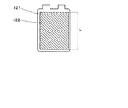
図3は、実施例のSOC表示装置におけるMFDのSOC表示を示す図であって、EV走行モード状態を示す図である。
MFD420におけるSOC表示は、バッテリを示すイラストレーション421に重畳して、SOCの増減に応じて長さが変化するバーグラフを表示したものである。
EV走行モードにおいては、図3に示すようにフルセグメント表示のバーグラフ422が表示される。
The SOC display in the
FIG. 3 is a diagram illustrating an SOC display of the MFD in the SOC display device of the embodiment, and is a diagram illustrating an EV traveling mode state.
The SOC display in the
In the EV running mode, a full segment
図3に示すフルセグメント表示のバーグラフ422は、例えば矩形に表示され、その上端部は、MFD420が有する画素群の1画素単位で、実質的に連続して上下するように構成されている。
SOCの減少に応じて、バーグラフ422の上端部は下降し、バーグラフ422の長さLが小さくなるようになっている。
図3においては、バーグラフ422の上端部が予め設定された表示範囲の上端部まで達した状態を示している。
このとき、バッテリ300のSOCは、EV走行モードにおけるSOC使用範囲の実用上の上限値(例えば85%)となっている。
一方、SOCが減少してEV走行モード→HV走行モード切替ライン(後述する図5を参照)に達した場合には、バーグラフ422の長さは実質的にゼロとなり、MFD420上に表示されなくなる(イラストレーション421のみが表示された状態となる。)。
The full segment
As the SOC decreases, the upper end portion of the
FIG. 3 shows a state in which the upper end portion of the
At this time, the SOC of the
On the other hand, when the SOC decreases and reaches the EV travel mode → HV travel mode switching line (see FIG. 5 described later), the length of the
図4は、実施例のSOC表示装置におけるMFDのSOC表示を示す図であって、HV走行モード状態を示す図である。
HV走行モードにおいては、バッテリを示すイラストレーション421に重畳して、複数(例えば8つ)のセグメント423a〜423hを上方から下方に順次配列して表示することが可能となっている。
HV走行モードにおいては、表示されるセグメントの個数によってSOCを示す。
HV走行モードにおけるSOC上限値(EV走行モード自動復帰ライン)の近傍においては、全てのセグメント423a〜423hが表示され、SOCの減少に応じて、上方のセグメント423aから順次非表示とされる。
SOCがHV走行モードにおける下限値近傍となった場合には、全てのセグメント423a〜423hが非表示となる(イラストレーション421のみが表示された状態となる。)。
FIG. 4 is a diagram showing the SOC display of the MFD in the SOC display device of the embodiment, and is a diagram showing the HV running mode state.
In the HV traveling mode, it is possible to display a plurality of (for example, eight)
In the HV traveling mode, the SOC is indicated by the number of displayed segments.
In the vicinity of the SOC upper limit value (EV travel mode automatic return line) in the HV travel mode, all the
When the SOC is close to the lower limit value in the HV travel mode, all the
ここで、フルセグメント表示におけるバーグラフ422と、8セグメント表示におけるセグメント423a〜423hは、色や輝度等の表示態様を異ならせて表示させる。
例えば、バーグラフ422を緑色で表示し、セグメント423a〜423hを青色で表示する構成とすることができる。
Here, the
For example, the
ハイブリッド統合制御ユニット240は、指針式SOCメータ411、及び、MFD420におけるフルセグメント表示において用いるフルセグメント表示用SOC値の算出処理を随時行う。
また、ハイブリッド統合制御ユニット240は、MFD420における8セグメント表示において用いる8セグメント表示用SOC値算出処理を行う。
指針式SOCメータ411及びMFD420がそれぞれ有するECUは、これらの各SOC値の算出値を受信して表示処理を行う。
また、MFD420のECUは、ハイブリッド統合制御ユニット240が出力するEV走行モード、HV走行モードの作動判別フラグを受信し、フルセグメント表示(EV走行モード時)と8セグメント表示(HV走行モード時)の切替えを行う。
The hybrid
Moreover, the hybrid
The ECUs included in the pointer
Further, the ECU of the
以下、実施例のハイブリッド車両におけるバッテリ300のSOC推移、及び、SOC変化に応じた走行モード切替動作について説明する。
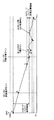
図5は、実施例のハイブリッド車両におけるSOC推移と走行モード切替動作の一例を示す図である。
図5において、縦軸はバッテリ300のSOCを示し、横軸は時間を示している。
Hereinafter, the SOC transition of the
FIG. 5 is a diagram illustrating an example of the SOC transition and the travel mode switching operation in the hybrid vehicle of the embodiment.
In FIG. 5, the vertical axis indicates the SOC of the
図5におけるA点においては、SOCは例えば約85%であり、実用上におけるバッテリ300の満充電状態となっている。
A点の状態からEV走行モードで走行を開始すると、回生発電等による一時的なSOCの回復はあり得るものの、走行や電装品の使用等による電力消費が通常は制動時の回生発電量等を上回るため、走行時間の経過に応じてSOCは徐々に減少する。
HV→EV自動復帰ラインであるB点、HV時常用域上限であるC点を順次通過し、EV→HV自動切替ラインであるD点のレベルまでSOCが減少すると、ハイブリッド統合制御ユニット240は、HV走行モードからEV走行モードへの切替えを自動的に行う。
EV→HV自動切替ラインは、例えば、SOCがHV走行モードにおけるSOC制御中心と実質的に一致する領域に設定される。
また、HV→EV自動復帰ラインは、例えば、EV走行モード復帰後におけるEV走行モードでの予測航続距離が所定値以上となる領域に設定される。
At point A in FIG. 5, the SOC is about 85%, for example, and the
If you start traveling in EV traveling mode from the state of point A, there is a possibility of temporary recovery of SOC due to regenerative power generation, etc., but power consumption due to traveling, use of electrical equipment, etc. usually reduces the amount of regenerative power generation during braking, etc. Therefore, the SOC gradually decreases as the running time elapses.
When the SOC decreases to the level of the D point which is the EV → HV automatic switching line through the B point which is the HV → EV automatic return line and the C point which is the upper limit of the HV normal use range in sequence, the hybrid
The EV → HV automatic switching line is set, for example, in a region where the SOC substantially coincides with the SOC control center in the HV traveling mode.
Further, the HV → EV automatic return line is set, for example, in a region where the predicted cruising distance in the EV travel mode after returning from the EV travel mode is a predetermined value or more.
HV走行モードにおいては、バッテリ300のSOCが、HV時常用域上限であるC点に相当するレベルと、HV時常用域下限であるE点に相当するレベルとの間となるように、ハイブリッド統合制御ユニット240は充放電制御を行なう。
また、例えば回生発電の機会が十分に得られないなどの何等かの理由によって、SOCがHV時常用域下限値を下回り、モータ走行負荷レベルであるF点に相当するレベルに達した場合には、モータ走行が不可能となり、さらにバッテリ使用領域下限であるG点に相当するレベルに達した場合には、エンジン10の出力でモータジェネレータ100を駆動して発電を行い、SOCがさらに減少しないよう充電する制御を行なう。
In the HV traveling mode, the hybrid integration is performed so that the SOC of the
In addition, when the SOC falls below the lower limit of the HV normal use range and reaches a level corresponding to the F point, which is the motor traveling load level, due to some reason such as insufficient regenerative power generation opportunities. When the motor travel becomes impossible and the level corresponding to the point G, which is the lower limit of the battery usage range, is reached, the
図6は、実施例のSOC表示装置における指針式SOCメータ及びMFDのSOC表示の推移の一例を示す図である。
図6においてA乃至Gは、上述した図5におけるA点乃至G点にそれぞれ対応する。
FIG. 6 is a diagram illustrating an example of transition of the SOC display of the pointer type SOC meter and the MFD in the SOC display device of the embodiment.
In FIG. 6, A to G correspond to the above-described points A to G in FIG.
指針式SOCメータ411は、A乃至Gの全領域において、共通の表示態様を維持しつつ、指針412の位置変化(揺動)のみによってSOCを表示する。
Aの状態においては、指針412は、満充電を示す目盛413aを指示している。
ここからSOCの減少に応じて指針412は反時計回りに回動し、Bの状態においては、HV走行モードからEV走行モードへの自動復帰ラインを示す目盛413fを指示する。
Cの状態になると、指針412は、HV時常用域上限を示す目盛413gを指示する。
Dの状態になると、指針412は、EV走行モードからHV走行モードへの自動切替ラインを示す目盛413hを指示する。
このとき、ドライバ413hは、指針412の目盛413hへの接近度合に基づいて、EV走行モードからHV走行モードへの切替を予測可能となっている。
ここからさらにSOCが減少してE,Fの状態となると、指針412は目盛413i側へ推移し、Gの状態となった際に目盛413iを指示する。
また、SOCが増加した場合は、指針412は時計回りに回動して、現在のSOCに対応する箇所を指示する。
The pointer-
In the state A, the
As the SOC decreases, the
In the state C, the
In the state D, the
At this time, the
When the SOC further decreases from this point to E and F states, the
When the SOC increases, the
MFD420におけるSOC表示は、Aの状態(EV走行モード)においては、図3に示すフルセグメント表示であって、バーグラフ422の長さ(高さ)が最大の状態となっている。
ここからSOCの減少に応じてバーグラフ422の長さは連続的に減少し、EV走行モードからHV走行モードへの自動切替ラインであるDの状態においては、バーグラフ422が表示されない状態となる。
EV走行モードからHV走行モードへ自動切替が行われる場合には、切替に先立ち、バーグラフ422が所定期間にわたって非表示状態となるように設定されている。
The SOC display in the
As the SOC decreases, the length of the
When the automatic switching from the EV traveling mode to the HV traveling mode is performed, the
EV走行モードからHV走行モードへの切替が行われると、MFD420におけるSOC表示は、図4に示す8セグメント表示へ変更される。
HV走行モードへの切替直後であるDの状態においては、セグメント423e〜423hが表示された状態となる。このとき、セグメント423a〜423dは非表示となっている。
When switching from the EV travel mode to the HV travel mode is performed, the SOC display in the
In the state D immediately after switching to the HV traveling mode, the
ここからSOCが減少すると、セグメント423e,セグメント423fが順次非表示となり、Eの状態ではセグメント423g,423hが表示された状態となる。
さらにSOCが減少し、Fの状態になると、セグメント423gが非表示となり、セグメント423hが表示された状態となる。
さらにSOCが減少し、Gの状態になると、セグメント423a〜423hは全て非表示となる。
When the SOC decreases from here, the
When the SOC further decreases to F state, the segment 423g is not displayed and the
When the SOC further decreases and the state becomes G, all the
一方、Dの状態から回生発電等によってSOCが増加すると、セグメント423d,423c,423b,423aが順次表示される。
Cの状態においては、セグメント423c〜423hが表示された状態となる。
HV走行モードからEV走行モードへの自動復帰ラインであるBの状態においては、セグメント423a〜423hが全て表示された状態となる。
HV走行モードからEV走行モードへの自動復帰(切替)が行われる場合には、切替に先立ち、セグメント423a〜423hの全てが所定期間にわたって表示状態となるように設定されている。
HV走行モードからEV走行モードへの切替が行われると、MFD420におけるSOC表示は、フルセグメント表示へ復帰し、バーグラフ422の下方部分の約3分の1の長さが表示される。
On the other hand, when the SOC increases from the state D by regenerative power generation or the like, the
In the state C, the
In the state B, which is an automatic return line from the HV travel mode to the EV travel mode, all the
When the automatic return (switching) from the HV traveling mode to the EV traveling mode is performed, all the
When switching from the HV traveling mode to the EV traveling mode is performed, the SOC display in the
以上説明したように、本実施例によれば、MFD420におけるSOC表示において、EV走行モード、HV走行モードのそれぞれにおいて利用されるSOC範囲を、バーグラフの表示範囲の全域に拡大して表示することによって、各走行モードにおけるSOCの推移を容易に把握することができる。
また、EV走行モードにおいてバーグラフ422が非表示となる最小値を示した場合には、直後(所定時間後)にHV走行モードへの変更が行われることを意味し、HV走行モードにおいてセグメント423a〜423hが全て表示されて最大値を示した場合には、直後(所定時間後)にEV走行モードへの変更が行われることを意味することから、現状のインジケータ表示から走行モードの切替が行われ得る時期などを容易に把握することができる。
また、指針式SOCメータ411を設けたことによって、MFD420の表示状態に関わらず、バッテリの全容量に対する現在のSOCの位置付けを容易に把握することができる。
さらに、指針式SOCメータ411に走行モード切替(復帰)ラインに相当する目盛を設けることによって、指針式SOCメータ411によっても走行モードの切替を容易に把握することが可能となる。
As described above, according to the present embodiment, in the SOC display on the
Further, when the
Further, by providing the pointer
Furthermore, by providing a scale corresponding to the travel mode switching (return) line in the pointer-
(変形例)
本発明は、以上説明した実施例に限定されることなく、種々の変形や変更が可能であって、それらも本発明の技術的範囲内である。
(1)ハイブリッド車両及びSOC表示装置の構成は上述した実施例に限定されず、適宜変更することが可能である。
例えば、実施例において車両はプラグイン充電機能を有するプラグインハイブリッド車両であったが、プラグイン充電機能を持たないハイブリッド車両であっても、エンジンを始動せずにモータのみによって走行する機能(EV走行モード)を有する車両の場合には本発明を適用することが可能である。
また、エンジンも実施例のようなガソリンエンジンに限らず、ディーゼルエンジンやその他の内燃機関を用いることができる。
(2)実施例の指針式SOCメータは、機械的に構成された指針及び目盛盤を有する構成としているが、これに代えて、このような指針式SOCメータに相当する画像をLCD等の画像表示装置に表示する構成としてもよい。
また、実施例においては、各領域を三色の目盛によって表示しているが、中間領域をグラデーションや複数色の塗り分けパターンによって表示してもよい。この場合、グラデーション領域の両端部、塗り分けパターン領域の両端部がそれぞれEV→HV自動切替ライン、HV→EV自動復帰ラインに対応するよう構成するとよい。
(3)実施例におけるMFDのSOC表示は、EV走行モードにおいてフルセグメント表示を行いHV走行モードにおいて8セグメント表示する構成となっているが、複数セグメント表示とフルセグメント表示との使い分けはこのような構成に限らず、適宜変更することができる。
例えば、EV走行モード、HV走行モードでともにフルセグメント表示としたり、ともに複数セグメント表示としてもよい。
また、複数セグメント表示におけるセグメント数も、実施例のような8セグメント表示に限らず、適宜増減することができる。
(Modification)
The present invention is not limited to the embodiments described above, and various modifications and changes are possible, and these are also within the technical scope of the present invention.
(1) The configurations of the hybrid vehicle and the SOC display device are not limited to the above-described embodiments, and can be changed as appropriate.
For example, in the embodiment, the vehicle is a plug-in hybrid vehicle having a plug-in charging function. However, even in a hybrid vehicle having no plug-in charging function, the function of running only by a motor without starting the engine (EV) The present invention can be applied to a vehicle having a travel mode.
The engine is not limited to the gasoline engine as in the embodiment, and a diesel engine or other internal combustion engine can be used.
(2) Although the pointer-type SOC meter of the embodiment has a mechanically configured pointer and scale plate, instead of this, an image corresponding to such a pointer-type SOC meter is an image of an LCD or the like. It is good also as a structure displayed on a display apparatus.
In the embodiment, each area is displayed with a three-color scale, but the intermediate area may be displayed with a gradation or a multi-color coating pattern. In this case, it is preferable that both ends of the gradation area and both ends of the painting pattern area correspond to the EV → HV automatic switching line and the HV → EV automatic return line, respectively.
(3) The SOC display of the MFD in the embodiment is configured to display full segments in the EV travel mode and display 8 segments in the HV travel mode, but the use of multiple segment display and full segment display is different. Not limited to the configuration, it can be changed as appropriate.
For example, both the EV travel mode and the HV travel mode may be full segment display, or both may be multi-segment display.
Also, the number of segments in the multi-segment display is not limited to the 8-segment display as in the embodiment, and can be increased or decreased as appropriate.
10 エンジン 20 トルクコンバータ
30 エンジンクラッチ 40 前後進切替部
50 バリエータ 51 プライマリプーリ
52 セカンダリプーリ 53 チェーン
60 出力クラッチ 70 フロントディファレンシャル
80 リアディファレンシャル 90 トランスファクラッチ
100 モータジェネレータ 210 エンジン制御ユニット
220 トランスミッション制御ユニット
230 モータジェネレータ制御ユニット
240 ハイブリッド統合制御ユニット
300 バッテリ 310 充電装置
410 コンビネーションメータ 411 指針式SOCメータ
412 指針 413a〜413i 目盛
420 マルチファンクションディスプレイ
421 イラストレーション 422 バーグラフ
423a〜423h セグメント
DESCRIPTION OF
Claims (4)
所定の表示範囲内で前記SOCの増減に応じて推移するインジケータ表示を表示するモード毎SOC表示手段を備え、
前記モード毎SOC表示手段は、前記EV走行モード時においては前記表示範囲の一方の端部及び他方の端部が前記EV走行モードにおいて使用されるSOC範囲の上限値及び前記EV走行モードから前記HV走行モードへの切替えが行われる第1の閾値に実質的に相当し、前記HV走行モード時においては前記表示範囲の一方の端部及び他方の端部が前記HV走行モードから前記EV走行モードへの切替えが行われる第2の閾値及び前記HV走行モードにおいて使用されるSOC範囲の下限値に実質的に相当し、前記EV走行モードから前記HV走行モードへの切替え実行に先立って前記EV走行モード時における前記インジケータ表示の最小値を表示すること
を特徴とするハイブリッド車両のSOC表示装置。 An EV traveling mode that prioritizes driving by only an electric motor, and an HV traveling mode that uses both an engine and an electric motor to drive and controls charging and discharging so that the SOC of the battery is within a predetermined range. An SOC display device,
SOC display means for each mode for displaying an indicator display that changes in accordance with the increase or decrease of the SOC within a predetermined display range;
The SOC display unit for each mode is configured such that, in the EV travel mode, one end and the other end of the display range are the upper limit value of the SOC range used in the EV travel mode and the HV from the EV travel mode. It substantially corresponds to the first threshold value for switching to the travel mode, and in the HV travel mode, one end and the other end of the display range are changed from the HV travel mode to the EV travel mode. The EV driving mode substantially corresponds to the second threshold value to be switched and the lower limit value of the SOC range used in the HV driving mode, and prior to the execution of switching from the EV driving mode to the HV driving mode. An SOC display device for a hybrid vehicle, wherein the minimum value of the indicator display at the time is displayed.
所定の表示範囲内で前記SOCの増減に応じて推移するインジケータ表示を表示するモード毎SOC表示手段を備え、
前記モード毎SOC表示手段は、前記EV走行モード時においては前記表示範囲の一方の端部及び他方の端部が前記EV走行モードにおいて使用されるSOC範囲の上限値及び前記EV走行モードから前記HV走行モードへの切替えが行われる第1の閾値に実質的に相当し、前記HV走行モード時においては前記表示範囲の一方の端部及び他方の端部が前記HV走行モードから前記EV走行モードへの切替えが行われる第2の閾値及び前記HV走行モードにおいて使用されるSOC範囲の下限値に実質的に相当し、前記HV走行モードから前記EV走行モードへの切替え実行に先立って前記HV走行モード時における前記インジケータ表示の最大値を表示すること
を特徴とするハイブリッド車両のSOC表示装置。 An EV traveling mode that prioritizes driving by only an electric motor, and an HV traveling mode that uses both an engine and an electric motor to drive and controls charging and discharging so that the SOC of the battery is within a predetermined range. An SOC display device,
SOC display means for each mode for displaying an indicator display that changes in accordance with the increase or decrease of the SOC within a predetermined display range;
The SOC display unit for each mode is configured such that, in the EV travel mode, one end and the other end of the display range are the upper limit value of the SOC range used in the EV travel mode and the HV from the EV travel mode. It substantially corresponds to the first threshold value for switching to the travel mode, and in the HV travel mode, one end and the other end of the display range are changed from the HV travel mode to the EV travel mode. Substantially equivalent to the second threshold value at which the switching is performed and the lower limit value of the SOC range used in the HV driving mode, and the HV driving mode prior to execution of switching from the HV driving mode to the EV driving mode. Display the maximum value of the indicator display at the time
An SOC display device for a hybrid vehicle characterized by the above.
前記全SOC表示手段の前記移動指標は、前記EV走行モード及び前記HV走行モードにおいて利用されるSOC範囲の最大値及び最小値にそれぞれ相当する位置の間で移動すること
を特徴とする請求項1又は請求項2に記載のハイブリッド車両のSOC表示装置。 A total SOC display means for displaying a movement index that moves according to an increase or decrease in the SOC and a fixed index that is arranged along a movement range of the movement index;
The movement index of the total SOC display means moves between positions corresponding to the maximum value and the minimum value of the SOC range used in the EV driving mode and the HV driving mode, respectively. Or the SOC display apparatus of the hybrid vehicle of Claim 2.
を特徴とする請求項3に記載のハイブリッド車両のSOC表示装置。
The fixed indicator of the indicator display means of the all SOC display means has a first indicator and a second indicator indicating locations corresponding to the first threshold value and the second threshold value, respectively. Item 4. The SOC display device for a hybrid vehicle according to Item 3.
Priority Applications (4)
| Application Number | Priority Date | Filing Date | Title |
|---|---|---|---|
| JP2015032488A JP6185945B2 (en) | 2015-02-23 | 2015-02-23 | SOC display device for hybrid vehicle |
| US15/011,280 US9895993B2 (en) | 2015-02-23 | 2016-01-29 | State of charge indicator of hybrid vehicle |
| DE102016102943.2A DE102016102943A1 (en) | 2015-02-23 | 2016-02-19 | Charge state display device |
| CN201610095173.5A CN105905118B (en) | 2015-02-23 | 2016-02-22 | The SOC display device of hybrid vehicle |
Applications Claiming Priority (1)
| Application Number | Priority Date | Filing Date | Title |
|---|---|---|---|
| JP2015032488A JP6185945B2 (en) | 2015-02-23 | 2015-02-23 | SOC display device for hybrid vehicle |
Publications (2)
| Publication Number | Publication Date |
|---|---|
| JP2016155399A JP2016155399A (en) | 2016-09-01 |
| JP6185945B2 true JP6185945B2 (en) | 2017-08-23 |
Family
ID=56577679
Family Applications (1)
| Application Number | Title | Priority Date | Filing Date |
|---|---|---|---|
| JP2015032488A Active JP6185945B2 (en) | 2015-02-23 | 2015-02-23 | SOC display device for hybrid vehicle |
Country Status (4)
| Country | Link |
|---|---|
| US (1) | US9895993B2 (en) |
| JP (1) | JP6185945B2 (en) |
| CN (1) | CN105905118B (en) |
| DE (1) | DE102016102943A1 (en) |
Families Citing this family (16)
| Publication number | Priority date | Publication date | Assignee | Title |
|---|---|---|---|---|
| JP6068531B2 (en) * | 2015-02-23 | 2017-01-25 | 富士重工業株式会社 | SOC display device for hybrid vehicle |
| JP6185945B2 (en) | 2015-02-23 | 2017-08-23 | 株式会社Subaru | SOC display device for hybrid vehicle |
| JP2017001509A (en) * | 2015-06-09 | 2017-01-05 | 株式会社デンソー | Engine control device |
| US10118500B2 (en) * | 2016-03-09 | 2018-11-06 | Ford Global Technologies, Llc | Battery capacity estimation based on open-loop and closed-loop models |
| JP6631358B2 (en) * | 2016-03-28 | 2020-01-15 | 三菱自動車工業株式会社 | Regenerative energy display |
| JP6372532B2 (en) * | 2016-09-05 | 2018-08-15 | トヨタ自動車株式会社 | Electric vehicle and control method of electric vehicle |
| JP6520902B2 (en) * | 2016-12-14 | 2019-05-29 | トヨタ自動車株式会社 | Connected vehicle |
| US10639994B2 (en) * | 2017-05-18 | 2020-05-05 | Mitsubishi Jidosha Kogyo Kabushiki Kaisha | Display device for hybrid vehicle |
| DE102017211790A1 (en) * | 2017-07-10 | 2019-01-10 | Bayerische Motoren Werke Aktiengesellschaft | User interface and method for a hybrid vehicle to display the state of charge |
| JP6981204B2 (en) * | 2017-11-24 | 2021-12-15 | トヨタ自動車株式会社 | vehicle |
| US11173805B2 (en) * | 2018-01-30 | 2021-11-16 | Karma Automotive Llc | State-of-charge display system |
| JP7045224B2 (en) * | 2018-03-12 | 2022-03-31 | 株式会社Subaru | Vehicle control system |
| JP6656284B2 (en) * | 2018-03-22 | 2020-03-04 | 本田技研工業株式会社 | Vehicle battery temperature display |
| GB201907140D0 (en) * | 2019-05-21 | 2019-07-03 | Rolls Royce Plc | Forecast of electric vehicles state of charge and energy storage capacity |
| CN110745000B (en) * | 2019-10-29 | 2021-09-28 | 上海天马有机发光显示技术有限公司 | Vehicle instrument and display method thereof, and vehicle speed monitoring display system |
| JP7382673B1 (en) * | 2022-09-07 | 2023-11-17 | キワ・アート・アンド・デザイン株式会社 | Mobility support system, mobility support program, and mobility support method |
Family Cites Families (24)
| Publication number | Priority date | Publication date | Assignee | Title |
|---|---|---|---|---|
| JP3982675B2 (en) * | 2002-01-17 | 2007-09-26 | 本田技研工業株式会社 | Battery remaining capacity display device |
| US7023216B2 (en) * | 2003-09-26 | 2006-04-04 | Ford Global Technologies, Llc | Indicator for use in vehicles having an energy storage device |
| JP2008056058A (en) | 2006-08-30 | 2008-03-13 | Mitsubishi Heavy Ind Ltd | Display device of cargo handling vehicle and hybrid cargo handling vehicle equipped with this display device |
| JP4155321B2 (en) * | 2006-09-25 | 2008-09-24 | トヨタ自動車株式会社 | Hybrid vehicle display device, hybrid vehicle, and hybrid vehicle display method |
| JP4251210B2 (en) * | 2006-11-07 | 2009-04-08 | トヨタ自動車株式会社 | Display device for hybrid vehicle |
| JP5141131B2 (en) * | 2007-08-08 | 2013-02-13 | トヨタ自動車株式会社 | Vehicle driving support apparatus and method |
| JP5086201B2 (en) * | 2008-07-30 | 2012-11-28 | 富士通テン株式会社 | Eco driving support device and method |
| JP5163407B2 (en) * | 2008-10-01 | 2013-03-13 | トヨタ自動車株式会社 | Hybrid vehicle |
| US8207841B2 (en) * | 2008-10-28 | 2012-06-26 | Ford Global Technologies, Llc | Vehicle information display and method |
| DE112009005220B4 (en) * | 2009-09-11 | 2018-07-26 | Toyota Jidosha Kabushiki Kaisha | Hybrid vehicle and a parameter display method for a hybrid vehicle |
| JP5223822B2 (en) * | 2009-09-11 | 2013-06-26 | トヨタ自動車株式会社 | Display device and hybrid vehicle including the same |
| US9506781B2 (en) * | 2009-10-22 | 2016-11-29 | Ford Global Technologies, Llc | Vehicle information display and method |
| JP5316466B2 (en) * | 2010-04-05 | 2013-10-16 | 三菱自動車工業株式会社 | Display device |
| JP5516027B2 (en) * | 2010-04-28 | 2014-06-11 | トヨタ自動車株式会社 | Vehicle control device |
| JP5472048B2 (en) * | 2010-11-10 | 2014-04-16 | 株式会社デンソー | In-vehicle secondary battery state quantification device |
| US8670885B2 (en) * | 2011-01-06 | 2014-03-11 | Ford Global Technologies, Llc | Information display system and method |
| US9696176B2 (en) * | 2011-01-06 | 2017-07-04 | Ford Global Technologies, Llc | Information display system and method |
| US8653960B2 (en) * | 2011-01-20 | 2014-02-18 | GM Global Technology Operations LLC | Vehicle gauge for displaying electric mode status and method of doing the same |
| US8836544B1 (en) * | 2011-02-17 | 2014-09-16 | Brunswick Corporation | Multifunctional displays and display systems for marine vessels |
| JP5704232B2 (en) * | 2011-05-10 | 2015-04-22 | トヨタ自動車株式会社 | Display device for hybrid vehicle |
| JP2013119349A (en) * | 2011-12-08 | 2013-06-17 | Toyota Motor Corp | Vehicle display device |
| KR101661593B1 (en) * | 2013-02-08 | 2016-09-30 | 도요타 지도샤(주) | Display device |
| JP6185945B2 (en) | 2015-02-23 | 2017-08-23 | 株式会社Subaru | SOC display device for hybrid vehicle |
| JP6068531B2 (en) * | 2015-02-23 | 2017-01-25 | 富士重工業株式会社 | SOC display device for hybrid vehicle |
-
2015
- 2015-02-23 JP JP2015032488A patent/JP6185945B2/en active Active
-
2016
- 2016-01-29 US US15/011,280 patent/US9895993B2/en active Active
- 2016-02-19 DE DE102016102943.2A patent/DE102016102943A1/en active Pending
- 2016-02-22 CN CN201610095173.5A patent/CN105905118B/en active Active
Also Published As
| Publication number | Publication date |
|---|---|
| JP2016155399A (en) | 2016-09-01 |
| US20160243959A1 (en) | 2016-08-25 |
| US9895993B2 (en) | 2018-02-20 |
| CN105905118A (en) | 2016-08-31 |
| DE102016102943A1 (en) | 2016-08-25 |
| CN105905118B (en) | 2019-01-01 |
Similar Documents
| Publication | Publication Date | Title |
|---|---|---|
| JP6185945B2 (en) | SOC display device for hybrid vehicle | |
| JP6068531B2 (en) | SOC display device for hybrid vehicle | |
| JP4725530B2 (en) | Vehicle display device | |
| US9168860B2 (en) | Vehicle display device | |
| JP4364279B2 (en) | Vehicle information display device and information display method | |
| JP5549726B2 (en) | Cruising range calculation device | |
| JP4530005B2 (en) | Hybrid vehicle | |
| US20110320088A1 (en) | System and method for displaying power status of hybrid vehicle | |
| US9718359B2 (en) | Braking display system and method | |
| CN102205844A (en) | Apparatus for hybrid engine control and method of manufacturing same | |
| WO2009008546A1 (en) | Hybrid vehicle and hybrid vehicle control method | |
| JP2016175485A (en) | vehicle | |
| CN104097629A (en) | Hybrid vehicle and control method thereof | |
| JP2015231796A (en) | Hybrid electric vehicle | |
| US9292178B2 (en) | Information display apparatus for a vehicle | |
| JP5712941B2 (en) | Vehicle and vehicle control method | |
| US11440409B2 (en) | Vehicle system and hybrid vehicle | |
| JP6327143B2 (en) | Hybrid vehicle | |
| KR101849980B1 (en) | Energy monitoring display system of re-ev vehicle | |
| JP4345771B2 (en) | Display device for hybrid vehicle | |
| JP2017136883A (en) | Electric vehicle |
Legal Events
| Date | Code | Title | Description |
|---|---|---|---|
| A131 | Notification of reasons for refusal |
Free format text: JAPANESE INTERMEDIATE CODE: A131 Effective date: 20160607 |
|
| A521 | Request for written amendment filed |
Free format text: JAPANESE INTERMEDIATE CODE: A523 Effective date: 20160805 |
|
| A02 | Decision of refusal |
Free format text: JAPANESE INTERMEDIATE CODE: A02 Effective date: 20170208 |
|
| A521 | Request for written amendment filed |
Free format text: JAPANESE INTERMEDIATE CODE: A523 Effective date: 20170427 |
|
| A911 | Transfer to examiner for re-examination before appeal (zenchi) |
Free format text: JAPANESE INTERMEDIATE CODE: A911 Effective date: 20170511 |
|
| TRDD | Decision of grant or rejection written | ||
| A01 | Written decision to grant a patent or to grant a registration (utility model) |
Free format text: JAPANESE INTERMEDIATE CODE: A01 Effective date: 20170704 |
|
| A61 | First payment of annual fees (during grant procedure) |
Free format text: JAPANESE INTERMEDIATE CODE: A61 Effective date: 20170728 |
|
| R150 | Certificate of patent or registration of utility model |
Ref document number: 6185945 Country of ref document: JP Free format text: JAPANESE INTERMEDIATE CODE: R150 |
|
| R250 | Receipt of annual fees |
Free format text: JAPANESE INTERMEDIATE CODE: R250 |
|
| R250 | Receipt of annual fees |
Free format text: JAPANESE INTERMEDIATE CODE: R250 |
|
| R250 | Receipt of annual fees |
Free format text: JAPANESE INTERMEDIATE CODE: R250 |
|
| R250 | Receipt of annual fees |
Free format text: JAPANESE INTERMEDIATE CODE: R250 |