JP6158209B2 - Reduced pressure tissue treatment system and method with reduced pressure dressing and associated valve - Google Patents
Reduced pressure tissue treatment system and method with reduced pressure dressing and associated valve Download PDFInfo
- Publication number
- JP6158209B2 JP6158209B2 JP2014543511A JP2014543511A JP6158209B2 JP 6158209 B2 JP6158209 B2 JP 6158209B2 JP 2014543511 A JP2014543511 A JP 2014543511A JP 2014543511 A JP2014543511 A JP 2014543511A JP 6158209 B2 JP6158209 B2 JP 6158209B2
- Authority
- JP
- Japan
- Prior art keywords
- valve
- fluid communication
- inlet
- tissue site
- reduced pressure
- Prior art date
- Legal status (The legal status is an assumption and is not a legal conclusion. Google has not performed a legal analysis and makes no representation as to the accuracy of the status listed.)
- Expired - Fee Related
Links
Images


Classifications
-
- A—HUMAN NECESSITIES
- A61—MEDICAL OR VETERINARY SCIENCE; HYGIENE
- A61M—DEVICES FOR INTRODUCING MEDIA INTO, OR ONTO, THE BODY; DEVICES FOR TRANSDUCING BODY MEDIA OR FOR TAKING MEDIA FROM THE BODY; DEVICES FOR PRODUCING OR ENDING SLEEP OR STUPOR
- A61M39/00—Tubes, tube connectors, tube couplings, valves, access sites or the like, specially adapted for medical use
- A61M39/22—Valves or arrangement of valves
- A61M39/24—Check- or non-return valves
-
- A—HUMAN NECESSITIES
- A61—MEDICAL OR VETERINARY SCIENCE; HYGIENE
- A61M—DEVICES FOR INTRODUCING MEDIA INTO, OR ONTO, THE BODY; DEVICES FOR TRANSDUCING BODY MEDIA OR FOR TAKING MEDIA FROM THE BODY; DEVICES FOR PRODUCING OR ENDING SLEEP OR STUPOR
- A61M1/00—Suction or pumping devices for medical purposes; Devices for carrying-off, for treatment of, or for carrying-over, body-liquids; Drainage systems
- A61M1/71—Suction drainage systems
- A61M1/74—Suction control
-
- A—HUMAN NECESSITIES
- A61—MEDICAL OR VETERINARY SCIENCE; HYGIENE
- A61M—DEVICES FOR INTRODUCING MEDIA INTO, OR ONTO, THE BODY; DEVICES FOR TRANSDUCING BODY MEDIA OR FOR TAKING MEDIA FROM THE BODY; DEVICES FOR PRODUCING OR ENDING SLEEP OR STUPOR
- A61M1/00—Suction or pumping devices for medical purposes; Devices for carrying-off, for treatment of, or for carrying-over, body-liquids; Drainage systems
- A61M1/71—Suction drainage systems
- A61M1/78—Means for preventing overflow or contamination of the pumping systems
-
- A—HUMAN NECESSITIES
- A61—MEDICAL OR VETERINARY SCIENCE; HYGIENE
- A61M—DEVICES FOR INTRODUCING MEDIA INTO, OR ONTO, THE BODY; DEVICES FOR TRANSDUCING BODY MEDIA OR FOR TAKING MEDIA FROM THE BODY; DEVICES FOR PRODUCING OR ENDING SLEEP OR STUPOR
- A61M1/00—Suction or pumping devices for medical purposes; Devices for carrying-off, for treatment of, or for carrying-over, body-liquids; Drainage systems
- A61M1/90—Negative pressure wound therapy devices, i.e. devices for applying suction to a wound to promote healing, e.g. including a vacuum dressing
- A61M1/91—Suction aspects of the dressing
- A61M1/912—Connectors between dressing and drainage tube
- A61M1/913—Connectors between dressing and drainage tube having a bridging element for transferring the reduced pressure from the connector to the dressing
-
- A—HUMAN NECESSITIES
- A61—MEDICAL OR VETERINARY SCIENCE; HYGIENE
- A61M—DEVICES FOR INTRODUCING MEDIA INTO, OR ONTO, THE BODY; DEVICES FOR TRANSDUCING BODY MEDIA OR FOR TAKING MEDIA FROM THE BODY; DEVICES FOR PRODUCING OR ENDING SLEEP OR STUPOR
- A61M1/00—Suction or pumping devices for medical purposes; Devices for carrying-off, for treatment of, or for carrying-over, body-liquids; Drainage systems
- A61M1/90—Negative pressure wound therapy devices, i.e. devices for applying suction to a wound to promote healing, e.g. including a vacuum dressing
- A61M1/91—Suction aspects of the dressing
- A61M1/915—Constructional details of the pressure distribution manifold
-
- A—HUMAN NECESSITIES
- A61—MEDICAL OR VETERINARY SCIENCE; HYGIENE
- A61M—DEVICES FOR INTRODUCING MEDIA INTO, OR ONTO, THE BODY; DEVICES FOR TRANSDUCING BODY MEDIA OR FOR TAKING MEDIA FROM THE BODY; DEVICES FOR PRODUCING OR ENDING SLEEP OR STUPOR
- A61M1/00—Suction or pumping devices for medical purposes; Devices for carrying-off, for treatment of, or for carrying-over, body-liquids; Drainage systems
- A61M1/90—Negative pressure wound therapy devices, i.e. devices for applying suction to a wound to promote healing, e.g. including a vacuum dressing
- A61M1/91—Suction aspects of the dressing
- A61M1/918—Suction aspects of the dressing for multiple suction locations
-
- A—HUMAN NECESSITIES
- A61—MEDICAL OR VETERINARY SCIENCE; HYGIENE
- A61M—DEVICES FOR INTRODUCING MEDIA INTO, OR ONTO, THE BODY; DEVICES FOR TRANSDUCING BODY MEDIA OR FOR TAKING MEDIA FROM THE BODY; DEVICES FOR PRODUCING OR ENDING SLEEP OR STUPOR
- A61M1/00—Suction or pumping devices for medical purposes; Devices for carrying-off, for treatment of, or for carrying-over, body-liquids; Drainage systems
- A61M1/71—Suction drainage systems
- A61M1/73—Suction drainage systems comprising sensors or indicators for physical values
- A61M1/732—Visual indicating means for vacuum pressure
-
- A—HUMAN NECESSITIES
- A61—MEDICAL OR VETERINARY SCIENCE; HYGIENE
- A61M—DEVICES FOR INTRODUCING MEDIA INTO, OR ONTO, THE BODY; DEVICES FOR TRANSDUCING BODY MEDIA OR FOR TAKING MEDIA FROM THE BODY; DEVICES FOR PRODUCING OR ENDING SLEEP OR STUPOR
- A61M1/00—Suction or pumping devices for medical purposes; Devices for carrying-off, for treatment of, or for carrying-over, body-liquids; Drainage systems
- A61M1/90—Negative pressure wound therapy devices, i.e. devices for applying suction to a wound to promote healing, e.g. including a vacuum dressing
- A61M1/92—Negative pressure wound therapy devices, i.e. devices for applying suction to a wound to promote healing, e.g. including a vacuum dressing with liquid supply means
-
- A—HUMAN NECESSITIES
- A61—MEDICAL OR VETERINARY SCIENCE; HYGIENE
- A61M—DEVICES FOR INTRODUCING MEDIA INTO, OR ONTO, THE BODY; DEVICES FOR TRANSDUCING BODY MEDIA OR FOR TAKING MEDIA FROM THE BODY; DEVICES FOR PRODUCING OR ENDING SLEEP OR STUPOR
- A61M39/00—Tubes, tube connectors, tube couplings, valves, access sites or the like, specially adapted for medical use
- A61M39/22—Valves or arrangement of valves
- A61M39/24—Check- or non-return valves
- A61M2039/2433—Valve comprising a resilient or deformable element, e.g. flap valve, deformable disc
- A61M2039/2446—Flexible disc
- A61M2039/2466—Flexible disc being fixed in its center
-
- A—HUMAN NECESSITIES
- A61—MEDICAL OR VETERINARY SCIENCE; HYGIENE
- A61M—DEVICES FOR INTRODUCING MEDIA INTO, OR ONTO, THE BODY; DEVICES FOR TRANSDUCING BODY MEDIA OR FOR TAKING MEDIA FROM THE BODY; DEVICES FOR PRODUCING OR ENDING SLEEP OR STUPOR
- A61M2205/00—General characteristics of the apparatus
- A61M2205/18—General characteristics of the apparatus with alarm
-
- A—HUMAN NECESSITIES
- A61—MEDICAL OR VETERINARY SCIENCE; HYGIENE
- A61M—DEVICES FOR INTRODUCING MEDIA INTO, OR ONTO, THE BODY; DEVICES FOR TRANSDUCING BODY MEDIA OR FOR TAKING MEDIA FROM THE BODY; DEVICES FOR PRODUCING OR ENDING SLEEP OR STUPOR
- A61M2205/00—General characteristics of the apparatus
- A61M2205/84—General characteristics of the apparatus for treating several patients simultaneously
Landscapes
- Health & Medical Sciences (AREA)
- Heart & Thoracic Surgery (AREA)
- Animal Behavior & Ethology (AREA)
- General Health & Medical Sciences (AREA)
- Anesthesiology (AREA)
- Biomedical Technology (AREA)
- Hematology (AREA)
- Life Sciences & Earth Sciences (AREA)
- Veterinary Medicine (AREA)
- Engineering & Computer Science (AREA)
- Public Health (AREA)
- Vascular Medicine (AREA)
- Pulmonology (AREA)
- External Artificial Organs (AREA)
- Media Introduction/Drainage Providing Device (AREA)
- Infusion, Injection, And Reservoir Apparatuses (AREA)
Description
関連出願の相互参照
本出願は、2011年11月23日出願の米国仮特許出願第61/563,529号明細書(REDUCED PRESSURE TISSUE TREATMENT SYSTEMS AND METHODS HAVING A REDUCED PRESSURE DRESSING AND ASSOCIATED VALVE)の優先権を主張し、この開示全体を、参照することにより本明細書に援用する。
CROSS REFERENCE TO RELATED APPLICATIONS This application is US Provisional Patent Application No. 61 / 563,529, filed November 23, 2011. And this disclosure is hereby incorporated by reference in its entirety.
本明細書に開示する主題は、概して、組織治療システムに関し、より詳細には、限定されるものではないが、減圧ドレッシングおよび関連の弁を有する減圧組織治療システムに関する。 The subject matter disclosed herein relates generally to tissue treatment systems, and more particularly, to, but not limited to, reduced pressure tissue treatment systems having reduced pressure dressings and associated valves.
臨床試験および実習から、組織部位に近接して減圧をもたらすことによって、組織部位における新しい組織の成長を増強および加速することが示されている。この現象の適用は多数あるが、減圧を行うことの特定の1つに、創傷の治療を含む。この治療(医学界では「陰圧閉鎖療法」、「減圧療法」、または「真空療法」と呼ばれることが多い)はいくつもの利点を提供し、それら利点には、上皮組織および皮下組織の移動、血流の改善、および創傷部位における組織の微小変形が含まれる。これらの利点と共に、肉芽組織の形成加速化や治癒時間の短縮が生じる。一般に、減圧は、減圧源によって、多孔質パッドまたは他のマニホールド装置を通して組織に行われる。多孔質パッドは、減圧を組織に分配しかつ組織から引き出された流体を運ぶことができる気泡または細孔を含む。多孔質パッドは、治療を促す他の構成要素を有するドレッシングに組み込まれていることが多い。 Clinical trials and practices have shown that enhancing and accelerating the growth of new tissue at a tissue site by providing a reduced pressure in proximity to the tissue site. Although there are many applications for this phenomenon, one particular one of performing decompression involves the treatment of wounds. This treatment (often referred to in the medical community as “negative pressure closure therapy”, “decompression therapy”, or “vacuum therapy”) offers a number of benefits, including migration of epithelial and subcutaneous tissue, Includes improved blood flow and tissue microdeformation at the wound site. Along with these advantages, the formation of granulation tissue is accelerated and the healing time is shortened. In general, vacuum is applied to tissue through a porous pad or other manifold device by a vacuum source. The porous pad includes bubbles or pores that can distribute the vacuum to the tissue and carry fluid drawn from the tissue. Porous pads are often incorporated into dressings with other components that facilitate treatment.
時には、複数の組織部位に対して治療を必要としている患者を治療する必要があることもある。これは、熱傷、戦争、または他の外傷によって負傷した患者に特に当てはまる。さらに、複数の組織部位は、現場で、または病院または他の医療施設への搬送中に治療する必要がある場合がある。 Sometimes it may be necessary to treat a patient in need of treatment for multiple tissue sites. This is especially true for patients injured by burns, wars, or other trauma. Further, multiple tissue sites may need to be treated on site or during transport to a hospital or other medical facility.
以下の詳細な説明において、本明細書の一部をなし、かつ本明細書で開示される主題を実施し得る特定の実施形態を説明するために示される添付図面を参照する。これらの実施形態は、当業者が本発明を実施できるようにするのに十分な程度、詳細に説明し、および詳細な説明の範囲から逸脱せずに、他の実施形態を使用し得ること、および論理的な構造上の、機械的な、電気的な、および化学的な変更がなされ得ることが理解される。当業者が、本明細書で説明する実施形態を実施できるようにするのに必要ではない詳細に関する説明を避けるために、当業者に公知の特定の情報に関する詳細な説明を省略し得る。それゆえ、以下の詳細な説明は、限定的ととられるべきではなく、例示的実施形態の範囲は、添付の特許請求の範囲によってのみ定義される。他に指定のない限り、本明細書では、「または」は相互排他性である必要はない。 In the following detailed description, references are made to the accompanying drawings that form a part hereof, and in which are shown by way of illustration specific embodiments in which the subject matter disclosed herein may be implemented. These embodiments are described in sufficient detail to enable those skilled in the art to practice the invention, and other embodiments may be used without departing from the scope of the detailed description. It is understood that mechanical, electrical, and chemical changes can be made in and logical structures. Detailed descriptions of specific information known to those of ordinary skill in the art may be omitted to avoid descriptions of details not necessary to enable one of ordinary skill in the art to practice the embodiments described herein. The following detailed description is, therefore, not to be taken in a limiting sense, and the scope of the exemplary embodiments is defined only by the appended claims. Unless otherwise specified herein, “or” need not be mutually exclusive.
用語「減圧」は、一般的に、治療が施されている組織部位における周囲圧力を下回る圧力を指す。ほとんどの場合、この減圧は、患者がいる場所の気圧を下回る。あるいは、減圧は、組織部位の組織に関連する静水圧を下回り得る。用語「真空」および「負圧」を、組織部位に適用される圧力を説明するために使用し得るが、組織部位で行われる実際の減圧は、通常完全な真空に関連付けられる減圧を著しく下回り得る。減圧は、初めに、組織部位の領域に流体の流れを生成し得る。組織部位の周囲の静水圧が所望の減圧に達すると、流れは弱まる可能性があるため、減圧が維持される。他に指定のない限り、本明細書で述べる圧力の値はゲージ圧である。同様に、減圧の上昇は、一般に、絶対圧の低下を指すが、減圧の低下は、一般に絶対圧の上昇を指す。 The term “reduced pressure” generally refers to a pressure below ambient pressure at the tissue site being treated. In most cases, this reduced pressure is below the air pressure where the patient is. Alternatively, the reduced pressure can be below the hydrostatic pressure associated with the tissue at the tissue site. The terms “vacuum” and “negative pressure” may be used to describe the pressure applied to a tissue site, but the actual vacuum performed at the tissue site can be significantly below the vacuum normally associated with a full vacuum. . The reduced pressure may initially generate a fluid flow in the region of the tissue site. When the hydrostatic pressure around the tissue site reaches the desired reduced pressure, the reduced pressure is maintained because the flow may weaken. Unless otherwise specified, the pressure values mentioned herein are gauge pressures. Similarly, an increase in vacuum generally refers to a decrease in absolute pressure, while a decrease in vacuum generally refers to an increase in absolute pressure.
本明細書で説明する組織治療システムおよび方法は、組織部位に対する流体(すなわち液体および気体)の流れを制御することによって、組織部位の治療を改善する。より具体的には、システムおよび方法は、組織部位への流体の逆流を防止する弁または他の流れ制御装置を含む。そのようなシステムは、単一の組織部位の治療だけでなく、複数の組織部位の治療にも有用とし得る。患者が、同時に治療する必要のある複数の組織部位または創傷を有するとき、例えば、複数の組織部位を単一の減圧源に接続することが好都合である場合がある。これは、(1)個々の組織部位の間に送られるマニホールドによって組織部位を「橋絡」し、かつ橋絡された組織部位の1つに減圧源を流体的に接続すること、または(2)別個の減圧チューブまたは他の導管を個々の組織部位それぞれに送ってから、マルチパスコネクタを使用してそれらチューブを減圧源に接続することによって達成され得る。これらのいずれの場合でも、組織部位は、共通のマニホールドまたは供給導管にそれぞれ流体的に接続され、これは、組織部位の1つから引き出された流体が別の組織部位に入る可能性を高める。特に組織部位の1つまたは複数に感染性物質が含まれる場合に、組織部位間の流体の交差汚染の問題をはらむ。これらの感染性物質が非感染組織部位に広がる場合があり、それにより、患者を悪化させ、かつ治癒にかかる時間を長期化させる。 The tissue treatment systems and methods described herein improve the treatment of tissue sites by controlling the flow of fluid (ie, liquids and gases) to the tissue site. More specifically, the system and method include a valve or other flow control device that prevents backflow of fluid to the tissue site. Such a system may be useful not only for the treatment of a single tissue site, but also for the treatment of multiple tissue sites. When a patient has multiple tissue sites or wounds that need to be treated simultaneously, it may be advantageous, for example, to connect multiple tissue sites to a single reduced pressure source. This can either (1) “bridge” the tissue site with a manifold sent between individual tissue sites and fluidly connect a reduced pressure source to one of the bridged tissue sites, or (2 It can be achieved by sending separate vacuum tubes or other conduits to each individual tissue site and then connecting them to a vacuum source using a multipath connector. In either of these cases, the tissue sites are each fluidly connected to a common manifold or supply conduit, which increases the likelihood that fluid drawn from one of the tissue sites will enter another tissue site. The problem of fluid cross-contamination between tissue sites, particularly when one or more of the tissue sites contains infectious substances. These infectious agents may spread to uninfected tissue sites, thereby exacerbating the patient and prolonging the time it takes to heal.
本明細書で説明するシステムおよび方法の構成要素である弁は、複数の組織部位間の交差汚染を防止し、かつ流体が組織部位に流れないようにする。下記でより詳細に示すように、いくつもの異なる弁のタイプを使用してもよく、および弁の位置決めは、特定の治療システムに依存して変化し得る。弁または他の流れ制御装置が存在することは、特に、複数の組織部位に関わる治療に有利であり、弁は、単一の組織部位の治療計画と同様に使用され得る。 Valves that are components of the systems and methods described herein prevent cross-contamination between multiple tissue sites and prevent fluid from flowing to the tissue sites. As will be shown in more detail below, a number of different valve types may be used and valve positioning may vary depending on the particular treatment system. The presence of a valve or other flow control device is particularly advantageous for treatment involving multiple tissue sites, and the valve can be used in the same manner as a treatment plan for a single tissue site.
ここで図面、および主に図1を参照すると、患者104の複数の組織部位102を同時に治療するためのシステム100の例示的実施形態が示されている。各組織部位102は、骨組織、脂肪組織、筋組織、皮膚組織、脈管組織、結合組織、軟骨、腱、靭帯、または任意の他の組織を含む、任意のヒト、動物、または他の生物の体の組織とし得る。組織部位102の治療は、流体、例えば滲出液や腹水の除去を含み得る。システム100を用いて、多数の部位、サイズ、および深さの組織を治療し得るが、システム100は、例えば、創傷(図示せず)を治療するために使用され得る。創傷は、表皮108、真皮110を通って、皮下組織112まで延在し得る。創傷の他の深さまたはタイプ、またはより一般的には、組織部位が治療され得る。説明のために3つの組織部位102を示すが、システム100を用いて任意の数の組織部位を治療し得ることを理解されたい。
Referring now to the drawings and primarily to FIG. 1, an exemplary embodiment of a
システム100は、複数の組織部位102に展開された複数の減圧ドレッシング114を含む。複数の減圧ドレッシング114の各々は、減圧を組織部位102に送達できかつ組織部位102から流体を除去するように動作可能な任意の種類のドレッシングとし得る。例示的一実施形態では、各減圧ドレッシング114は、ドレッシング充填材すなわちマニホールド116、およびカバーまたはシール部材118を含む。シール部材118は、取付装置122を使用して患者104に剥離可能に結合されている。取付装置122は多数の形態をとり得る。例えば、取付装置122は、シール部材118全体の周囲または一部分に延在する医学的に容認できる感圧接着剤、両面ドレープテープ、糊、親水コロイド、ヒドロゲル、または他のシール装置または要素とし得る。各減圧ドレッシング114に関し、シール部材118は、マニホールド116と、治療される組織部位102とを含む実質的な密閉空間124を形成し得る。
各減圧ドレッシング114に関し、マニホールド116は、関連の組織部位102に対して減圧を行ったり、流体を送達したり、または組織部位102から流体を除去したりするのを支援するために設けられる物体または構造である。マニホールド116は、マニホールド116の周りの組織部位102に提供されかつそこから除去される流体を分配することができる複数の流路または流れ経路を含む。例示的一実施形態では、流路または流れ経路は相互に接続されて、組織部位102に提供されるかまたはそこから除去される流体の分配を改善し得る。マニホールド116は、以下のうちの1つまたは複数を含む:組織部位102と接触して配置されかつ組織部位102に減圧を分配することができる生体適合性材料;例えば、気泡質の発泡体、連続気泡発泡体、多孔性組織集合体、液体、ゲル、および流路を含むまたは硬化して流路を含む発泡体などの、流路を形成するように配置された構造要素を有する装置;多孔質材、例えば発泡体、ガーゼ、フェルトのマット、または特定の生物学的適用に好適な任意の他の材料;または流路の機能を果たす複数の連続気泡または細孔を含む多孔質発泡体、例えば、Kinetic Concepts,Incorporated(San Antonio、Texas)製のGranuFoam(登録商標)材などのポリウレタン製の連続気泡の網状発泡体;生体再吸収性材料;または足場材料。場合によっては、マニホールド116はまた、薬剤、抗菌薬、成長因子、および様々な溶液などの流体を組織部位102に分配するためにも使用し得る。マニホールド116にまたはマニホールド116上に、吸収材料、ウィッキング材料、疎水性材料、および親水性材料などの他の層も含まれ得る。
For each reduced
例示的非限定的な一実施形態では、マニホールド116は、減圧ドレッシング114の使用後に患者の体に留まってもよい生体再吸収性材料から構成し得る。好適な生体再吸収性材料は、限定はされないが、ポリ乳酸(PLA)とポリグリコール酸(PGA)とのポリマーブレンドを含み得る。ポリマーブレンドはまた、限定はされないが、ポリカーボネート、ポリフマレート、およびカプララクトンを含み得る。マニホールド116は、新しい細胞増殖のための足場としての機能をさらに果たしても、細胞増殖を促進するためにマニホールド116と足場材料が一緒に使用されてもよい。足場は、細胞増殖または組織形成を増進させるまたは促進するのに使用される物体または構造体であり、例えば、細胞増殖のテンプレートを提供する三次元の多孔質構造体である。足場材料の実例は、リン酸カルシウム、コラーゲン、PLA/PGA、コーラルヒドロキシアパタイト(coral hydroxy apatite)、カーボネート、または加工された同種移植片材料を含む。
In one exemplary, non-limiting embodiment, the manifold 116 can be constructed from a bioresorbable material that may remain on the patient's body after use of the reduced pressure dressing 114. Suitable bioresorbable materials can include, but are not limited to, polymer blends of polylactic acid (PLA) and polyglycolic acid (PGA). The polymer blend can also include, but is not limited to, polycarbonate, polyfumarate, and coupler lactone.
シール部材118は、流体シールをもたらす任意に材料とし得る。流体シールは、特定の減圧源または関連のサブシステムから与えられた減圧を所望の部位で維持するのに適切なシールである。シール部材118は、例えば、不透過性または半透過性のエラストマー材料とし得る。半透過性材料に関し、透過性は、所与の減圧源に対して、所望の減圧を維持し得る程度に十分に低い必要がある。シール部材118は、各減圧ドレッシング114用の別個の部片としても、複数の減圧ドレッシング114の全てに使用される1つの連続的なシートとしてもよい。
The
図1に図示する実施形態では、シール部材118の各々はアパーチャ128を含む。システム100は、さらに、アパーチャを覆って配置された弁132と、3つの弁132およびドレッシング114を覆って位置決めされた橋絡用マニホールド136とを含む。各弁132(図2〜6を参照して下記で実施形態をより詳細に説明する)は、対応するシール部材118に封止式に取り付けられて、組織部位102とのいずれの流体連通も弁132を通って送られ得るようにし得る。橋絡用マニホールド136の機能は、先に説明したマニホールド116と同様であり、橋絡用マニホールド136は、多岐に分配する(manifolding)能力を提供する。実際に、橋絡用マニホールド136は、マニホールド116に対して先に挙げた材料のいずれかから作製し得る。各組織部位102と流体連通させて橋絡用マニホールド136を配置することによって、橋絡用マニホールド136に供給される減圧は、組織部位102の各々に分配され、それにより、各組織部位102から流体を除去し、かつ組織部位102を減圧にさらすことができ得る。
In the embodiment illustrated in FIG. 1, each of the
橋絡用マニホールド126を覆って橋絡用カバー144が位置決めされ、かつ橋絡用カバー144の周囲に沿って、シール部材118、患者の表皮108のいずれか、または場合によってはそれら双方に対して封止される。橋絡用カバー144は実質的な密閉空間146を提供し、その内部に橋絡用マニホールド136がある。橋絡用カバー144が存在することによって、橋絡用マニホールド136は、流体および圧力を適切に分配できる。橋絡用カバー144にはアパーチャ148が位置決めされて、密閉空間146との流体連通をもたらす。図1では、アパーチャ148を、最も右側の組織部位102の上側に位置決めされているとして示すが、その代わりに、アパーチャ148は、任意の特定の組織部位102の上側に位置決めしても、代替的に、2つの組織部位の中間に位置決めしてもよい。
A bridging
橋絡用カバー144の上に減圧アダプタ152が位置決めされ、かつアパーチャ148を通って密閉空間146に流体的に接続されている。減圧アダプタ152と密閉空間146との間の流体接続部を封止するために別個のカバー154が設けられ得る。減圧アダプタ152は、密閉空間148に減圧を送達するための任意の装置とし得る。例えば、減圧アダプタ152は、以下のうちの1つを含み得る:KCI(San Antonio、Texas)から入手可能なT.R.A.C.(登録商標)PadまたはSensa T.R.A.C.(登録商標)Pad;または別の装置またはチューブ。減圧アダプタ152にマルチルーメン減圧送達チューブ156または導管が流体的に結合される。マルチルーメン減圧送達チューブ156は、第1の端部157および第2の端部159を有する。マルチルーメン減圧送達チューブ156の第1の端部157は、治療ユニット158に流体的に結合される。マルチルーメン減圧送達チューブ156は、少なくとも1つの圧力サンプリングルーメンおよび少なくとも1つの減圧供給ルーメンを含む。圧力サンプリングルーメンは、各組織部位102の圧力に近似し得る、密閉空間148内の近似圧力を判断するための圧力をもたらす。減圧供給ルーメンは、減圧ドレッシング114に減圧を送達し、かつそこから流体を受け取る。マルチルーメン減圧送達チューブ156の第2の端部159は、減圧アダプタ152に流体的に結合される。
A
一実施形態では、治療ユニット158は、減圧源164と流体連通する流体閉じ込め部材162を含む。図1に示す実施形態では、流体閉じ込め部材162は、組織部位102からの流体を収集するためのチャンバを含む収集キャニスターである。あるいは、流体閉じ込め部材162は、吸収材料、または流体を収集できる任意の他の容器、装置、または材料とし得る。
In one embodiment,
引き続き図1を参照して説明すると、減圧源164は電動真空ポンプとし得る。別の実装例では、その代わりに、減圧源164は、電力を必要としない、手動で作動できるまたは手動で充電できるポンプとし得る。一実施形態では、減圧源164は、ドレッシング114から離れて、またはドレッシング114に隣接して位置決めされ得る1つまたは複数の圧電作動型マイクロポンプとし得る。その代わりに、減圧源164は、病院および他の医療施設で利用可能なものなどの、任意の他のタイプのポンプ、あるいは、壁面吸い込みポートまたは空気送達ポートとし得る。減圧源164は、治療ユニット158内に収容されても、それと共に使用されてもよく、治療ユニットはまた、センサ、処理装置、アラームインジケータ、メモリ、データベース、ソフトウェア、表示装置、およびユーザインターフェース166を含み、組織部位102へ減圧治療を行うのをさらに容易にする。一例では、減圧源164にまたはその付近に圧力検出センサ(図示せず)を配置し得る。圧力検出センサは、マルチルーメン減圧送達チューブ156の圧力サンプリングルーメンを経由して、減圧アダプタ152から圧力データを受信し得る。圧力検出センサは、減圧源164によって送達された減圧を監視および制御する処理装置と通信し得る。
Continuing with reference to FIG. 1, the
組織部位に行われる減圧の量および性質は、一般に、用いられる特定の治療計画に依存して変動するが、減圧は、一般に、約−5mm Hg(−667Pa)〜約−500mm Hg(−66.7kPa)、より典型的には、約−75mm Hg(−9.9kPa)〜約−300mm Hg(−39.9kPa)とし得る。一部の実施形態では、減圧源164は、Kinetic Concepts,Inc.(San Antonio、Texas)から入手可能なV.A.C.Freedom、V.A.C.ATS、InfoVAC、ActiVAC、AbTheraまたはV.A.C.Ulta治療ユニットとし得る。
The amount and nature of the reduced pressure applied to the tissue site will generally vary depending on the particular treatment plan used, but reduced pressure is generally between about −5 mm Hg (−667 Pa) to about −500 mm Hg (−66. 7 kPa), more typically from about −75 mm Hg (−9.9 kPa) to about −300 mm Hg (−39.9 kPa). In some embodiments, the reduced
図2および図3を参照すると、弁210の例示的実施形態が示されている。弁210は、弁本体214および弁蓋218を含み、これらは、好ましくは、耐久性のあるハウジングを弁に提供できるポリマー材料、金属、または任意の他の材料から形成される。弁本体214および弁蓋218は、一緒に結合して、内室222を形成できる。内室222は、入口壁226および出口壁230によって画成されている。弁本体214は少なくとも1つの入口ポート238を含み、および弁蓋218は少なくとも1つの出口ポート242を含む。入口壁226にはシールリング250が配置され、好ましくは入口ポート238を取り囲む。シールリング250は、入口壁226の一体部分とし、かつ入口壁226と同じ材料で作製し得るが、その代わりに、シールリング250は、異なる材料から作製してもよく、入口壁226にオーバーモールドされるかまたは他の方法でそこに結合される。一実施形態では、シールリング250は、エラストマー性材料としても、または他の可撓性材料としてもよく、入口壁226に接合されるかまたは他の方法でそこに結合される。
With reference to FIGS. 2 and 3, an exemplary embodiment of
弁210は、さらに、外周領域264および中心領域268を有する弁フラップ260を含む。弁フラップ260は、ポリマーまたは金属材料、または任意の材料から作製され、シールリング250と協働して、弁210を通る流体の流れを制御し得る。弁フラップ260は内室222内に位置決めされ、弁フラップ260の外周領域264がシールリング250と接触する。弁フラップ260の中心領域268は、入口壁226に接合されるかまたは他の方法でそこに結合される。弁フラップ260は、図2および図3に示すように湾曲した構成で予め形成され得るが、入口壁226への弁フラップ260の結合には、好ましくは、弁フラップ260が弾性変形することを必要とする。弁フラップ260のこの弾性変形は、弁フラップ260にプレストレスを与え、これにより、弁フラップ260とシールリング250との間のシールをより良好にする。
The
図2では、弁フラップ260、それゆえ弁210が閉鎖位置にある状態で示す。閉鎖位置では、弁フラップ260は、シールリング250に接触したままであり、この接触により、実質的に、流体が弁210を通って流れないようにする。図3では、弁フラップ260、それゆえ弁210が開放位置にある状態で示す。開放位置では、弁フラップ260は、弾性的に変形しており、もはやシールリング250と接触していない。弁フラップ260が開放している間、流体は、弁210を通って流れることができる。
In FIG. 2, the
一実施形態では、開放位置への弁フラップ260の移動は、入口ポート238における流体の圧力が、出口ポート242における流体の圧力を上回ると、発生する。この好都合な圧力差によって、弁フラップ260を、シールリング250から離れるように動かすことができ、流体を入口ポート238から出口ポート242へ流すことができる。反対に、出口ポート242における流体の圧力が、入口ポート238における流体の圧力を上回ると、流体は、弁フラップ260に付勢力を加えて、シールリング250との接触を維持する。このシールリング250との接触は、実質的に、出口ポート242から入口ポート238への流体の流れを防止する。継続的に弁フラップ260を開閉させる能力は、弁フラップ260が弾性的に変形する能力によってもたらされる。この弾性変形は、弁フラップ260の材料特性および物理的寸法(すなわち厚さ)によってもたらされ得る。
In one embodiment, movement of the
シールリング250は、好ましくは、少なくとも1つの入口ポート238の周りに継続的に配置されるが、用語「リング」は、シールリング250が円形に限定されることを暗示することを意味しない。シールリング250は、弁フラップ260がシールリング250と接触すると、出口ポート242から入口ポート238を流体的に隔離できる任意の特定の形状とし得る。
The
弁210は、図1のシステム100、または任意の他の減圧治療システムと共に使用して、組織部位への流体の流れを防止し得る。このようにして、弁210は、複数の組織部位が共通の減圧源に連続して接続されるときに、組織部位間の交差汚染の防止を支援する。同様に、圧力変化によって一瞬、流体を組織部位に押し返そうとする差圧を生じ得るときに、弁210は、単一の組織部位から除去された流体の逆流を防止できる。弁210は、ドレッシング114(図1参照)に対する弁132の配置と同様に、ドレッシングに隣接して配置され得るか、または代替的に、本明細書で説明するように、弁210は、他のシステム構成要素に対して動作可能に位置決めされ得る。弁210は、一般に、入口ポート238が組織部位の近く、かつ出口ポート242が減圧源の近くになるような向きにされる。
The
図2および図3に示すように、弁フラップ260の移動は、弁フラップ260の表裏間での差圧に依存する。一実施形態では、弁210は、単に、逆止弁と同様に、流れの方向制御をもたらすように構成し得る。そのような構成では、閉鎖位置から開放位置へ弁フラップ260を動かすために必要な力は、比較的小さい。より具体的には、流れを出口ポート242へ向かわせるのに好都合である、弁フラップ260の表裏間での比較的小さい圧力差が、弁フラップ260を開放位置に移動させることができる。この同じ構成では、流れを入口ポート238へ向かわせるのに好都合である、弁フラップ260の表裏間での比較的小さい圧力差が、弁フラップ260を閉鎖位置に保持できる。別の実施形態では、弁フラップ260は、開放位置へ動かすために、より大きい差圧を必要とするように構成し得る。弁フラップ260を開放させるために必要な差圧を大きくすることによって、弁210は、本質的に、弁を開放するために「クラッキング圧」を必要とする調整弁になる。このクラッキング圧は、弁を開放するために、減圧が特定のレベル(すなわち絶対圧が十分に低い)に確実に達するようにする。
As shown in FIGS. 2 and 3, the movement of the
図4を参照すると、弁410の例示的実施形態が示されている。弁410は、弁本体414および弁蓋418を含み、これらは、好ましくは、耐久性のあるハウジングを弁に提供できるポリマー材料、金属、または任意の他の材料から形成される。弁本体414および弁蓋418は、一緒に結合して、内室422を形成できる。内室422は、入口壁426および出口壁430によって画成されている。弁本体414は、少なくとも1つの入口ポート438を含み、および弁蓋418は少なくとも1つの出口ポート442を含む。入口壁426にはシールリング450が配置され、かつ好ましくは入口ポート438を取り囲む。シールリング450は入口壁426の一体部分とし、かつ入口壁426と同じ材料から作製し得るが、その代わりに、シールリング450は、異なる材料から作製して、入口壁426にオーバーモールドされるかまたは他の方法で結合される。一実施形態では、シールリング450はエラストマー性材料としても、または他の可撓性材料としてもよく、入口壁426に接合されるかまたは他の方法でそこに結合される。
Referring to FIG. 4, an exemplary embodiment of
弁410は、さらに、外周領域464および中心領域468を有する弁フラップ460を含む。弁フラップ460と、弁410の動作とは、本質的に、図2および図3に示す弁210と同様である。弁フラップ260と同様に、弁フラップ460は内室422内に位置決めされ、弁フラップ460の外周領域464がシールリング450に接触する。弁フラップ460の中心領域468は入口壁426に接触するが、弁210とは異なり、弁フラップ460は、入口壁426に接合または結合されない。その代わり、少なくとも1つの突出部470が弁蓋418から延出する。弁蓋418および弁本体414が組立てられると、突出部470は弁フラップ460に力を加えて、弁フラップ460を、入口壁426と接触するように付勢する。ここでも、弁フラップ460のこの弾性変形によって弁フラップ460にプレストレスを与え、これにより、弁フラップ460とシールリング450との間に良好なシールを形成する。
図4では、弁フラップ460、それゆえ弁410が閉鎖位置にある状態で示す。弁410は、弁210に関して説明したものと同様に動作し、および弁410は、図1のシステム100、または任意の他の減圧治療システムと共に使用して、組織部位への流体の流れを防止する。このように、弁410は、複数の組織部位が共通の減圧源に連続して接続されるときに、組織部位間の交差汚染の防止を支援する。同様に、弁410は、圧力変化によって一瞬、流体を組織部位に押し返そうとする差圧を生じ得るときに、単一の組織部位から除去された流体の逆流を防止できる。弁410は、ドレッシング114に対する弁132の配置(図1参照)と同様に、ドレッシングに隣接して配置され得るか、または代替的に、本明細書で説明するように、弁410は、他のシステム構成要素に対して動作可能に位置決めされ得る。弁410は、一般に、入口ポート438が組織部位の近く、および出口ポート442が減圧源の近くになるような向きにされる。
In FIG. 4, the
弁フラップ460の移動は、弁フラップ460の表裏間での差圧に依存する。一実施形態では、弁410は、単に、逆止弁と同様に、流れの方向制御をもたらすように構成し得る。そのような構成では、弁フラップ460を閉鎖位置から開放位置へ移動させるために必要な力は、比較的小さい。より具体的には、流れを出口ポート442に向かわせるのに好都合である、弁フラップ460の表裏間での比較的小さい圧力差が、弁フラップ460を開放位置に移動させることができる。この同じ構成では、流れを入口ポート438に向かわせるのに好都合である、弁フラップ460の表裏間での比較的小さい圧力差が、弁フラップ460を閉鎖位置に保持する。別の実施形態では、弁フラップ460は、開放位置に移動させるために、より高い差圧を必要とするように構成され得る。弁フラップ460を開放させるために必要な差圧を高くすることによって、弁410は、本質的に、弁を開放するために「クラッキング圧」を必要とする調整弁になる。このクラッキング圧は、弁410を開放するために、減圧が特定のレベル(すなわち絶対圧が十分に低い)に確実に達するようにする。
The movement of the
図5を参照すると、弁510の例示的実施形態が示されている。弁510は、弁本体514および弁蓋518を含み、これらは、好ましくは、耐久性のあるハウジングを弁に提供できるポリマー材料、金属、または任意の他の材料から形成される。弁本体514および弁蓋518は一緒に結合して、内室522を形成できる。内室522は、入口壁526および出口壁530によって画成されている。弁本体514は少なくとも1つの入口ポート538を含み、および弁蓋518は少なくとも1つの出口ポート542を含む。入口壁526にはシール部材550が配置され、好ましくは入口ポート538を取り囲む。シール部材550は、好ましくはダックビル弁または制御装置の形状に構成され、かつ一対のフラッパー560を含み、これらフラッパーは、弁510が閉鎖位置(図5参照)にあるときに一緒にされる。フラッパー560は、フラッパー560の形状および弾性特性によって、一緒にされ得る。あるいは、フラッパー560は、シール部材550の内部または外部に配置された付勢部材またはバネ装置によって一緒にされ得る。
Referring to FIG. 5, an exemplary embodiment of
フラッパー560と、弁510の動作とは、図2〜4に示す弁210および410の動作と同様である。弁510は、図1のシステム100、または任意の他の減圧治療システムと共に使用して、組織部位への流体の流れを防止し得る。このようにして、弁510は、複数の組織部位が共通の減圧源に連続して接続されるときに、組織部位間の交差汚染の防止を支援する。同様に、弁510は、圧力変化によって一瞬、流体を組織部位に押し返そうとする差圧を生じ得るときに、単一の組織部位から除去された流体の逆流を防止できる。弁510は、ドレッシング114に対する弁132の配置(図1参照)と同様に、ドレッシングに隣接して配置され得るか、または代替的に、本明細書で説明するように、弁510は、他のシステム構成要素に対して動作可能に位置決めされ得る。弁510は、一般に、入口ポート538が組織部位の近くおよび出口ポート542が減圧源の近くになるような向きにされる。
The operation of
フラッパー560の移動は、シール部材550の表裏間での差圧に依存する。一実施形態では、弁510は、単に、逆止弁と同様に流れの方向制御をもたらすように構成し得る。そのような構成では、フラッパー560を離す(すなわちフラッパー560を開放位置に移動させる)ために必要な力は、比較的小さい。より具体的には、流れを出口ポート542に向かわせるのに好都合である、シール部材550の表裏間での比較的小さい圧力差が、フラッパー560を開放位置に移動させることができる。この同じ構成では、流れを入口ポート538に向かわせるのに好都合である、シール部材550の表裏間での比較的小さい圧力差が、フラッパー560を閉鎖位置に保持する。別の実施形態では、フラッパー560は、開放位置に移動させるために、より高い差圧を必要とするように構成され得る。フラッパー560を開放させるために必要な差圧を高くすることによって、弁510は、本質的に、弁を開放するために「クラッキング圧」を必要とする調整弁になる。このクラッキング圧は、弁510を開放するために、減圧が特定のレベル(すなわち絶対圧が十分に低い)に確実に達するようにする。
The movement of the
図6を参照すると、弁610の例示的実施形態が示されている。弁610は、弁本体614および弁蓋618を含み、これらは、好ましくは、耐久性のあるハウジングを弁に提供できるポリマー材料、金属、または任意の他の材料から形成される。弁本体614および弁蓋618は一緒に結合でき、内室622を形成する。内室622は、入口壁626および出口壁630によって画成されている。弁本体614は少なくとも1つの入口ポート638を含み、および弁蓋618は少なくとも1つの出口ポート642を含む。入口壁626にはシールリング650が配置され、好ましくは、入口ポート638を取り囲む。シールリング650は、入口壁626の一体部分とし、かつ入口壁626と同じ材料から作製し得るが、その代わりに、シールリング650は、異なる材料から作製して、入口壁626にオーバーモールドされても、または他の方法でそこに結合されてもよい。一実施形態では、シールリング650は、エラストマー性材料としても、または他の可撓性材料としてもよく、入口壁626に接合されるかまたは他の方法でそこに結合される。
Referring to FIG. 6, an exemplary embodiment of
弁610は、さらに、外周領域664および中心領域668を有する弁フラップ660を含む。弁フラップ660と、弁610の動作とは、図2および図3に示す弁210の動作とある程度似ている。弁フラップ260と同様に、弁フラップ660は内室622内に位置決めされて、弁フラップ660の外周領域664がシールリング650に接触する。しかしながら、弁フラップ260とは異なり、弁フラップ660は、湾曲した形状に弾性的に変形しないため、弁フラップ660の中心領域668が入口壁626に接触する。その代わりに、弁フラップ660は、より剛体の材料から作製されており、実質的に平面的な構成のままである。弁フラップ660は、バネ672によって、閉鎖位置にあるシールリング650(図示せず)と接触するように付勢される。バネ672によって弁フラップ660に加えられる力は、距離Dを変更することによって調整され、そのバネは、予め圧縮されている。シャフト676および調整部材682によって距離Dを調整できるようにし、それにより、弁フラップ660を開放位置(図6参照)に移動させるために必要な力の調整機能を生じる。
弁610は、弁210の説明と同様に動作し、および弁610は、図1のシステム100、または任意の他の減圧治療システムと共に使用して、組織部位への流体の流れを防止する。このようにして、弁610は、複数の組織部位が共通の減圧源に連続して接続されるときに、組織部位間の交差汚染の防止を支援する。同様に、弁610は、圧力変化によって一瞬、流体を組織部位に押し返そうとする差圧を生じ得るときに、単一の組織部位から除去された流体の逆流を防止できる。弁610は、ドレッシング114に対する弁132の配置(図1参照)と同様に、ドレッシングに隣接して配置され得るか、または代替的に、弁610は、本明細書で説明するように、他のシステム構成要素に対して動作可能に位置決めされ得る。弁610は、一般に、入口ポート638が組織部位の近く、および出口ポート642が減圧源の近くになるような向きにされる。
弁フラップ660の移動は、弁フラップ660の表裏間での差圧に依存する。一実施形態では、弁610は、単に、逆止弁と同様に、流れの方向制御をもたらすように構成し得る。そのような構成では、閉鎖位置から開放位置へ弁フラップ660を移動させるために必要な力は、比較的小さい。より具体的には、流れを出口ポート642に向かわせるのに好都合である、弁フラップ660の表裏間での比較的小さい圧力差が、弁フラップ660を開放位置に移動させることができる。この同じ構成では、流れを入口ポート638に向かわせるのに好都合である、弁フラップ660の表裏間での比較的小さい圧力差が、弁フラップ660を閉鎖位置に保持する。別の実施形態では、弁フラップ660は、開放位置に移動させるために、より高い差圧を必要とするように構成され得る。弁フラップ660を開放させるために必要な差圧を高くすることによって、弁610は、本質的に、弁を開放するために「クラッキング圧」を必要とする調整弁になる。このクラッキング圧は、弁610を開放させるために、減圧が特定のレベル(すなわち絶対圧が十分に低い)に確実に達するようにする。
The movement of the
圧力を調整するまたは流体の流れの方向を制御するための複数の弁の構成を説明したが、本明細書で説明する減圧治療システムと共に他の弁の構成を使用し得ることを認識されたい。他の弁の構成は、限定されるものではない、ボール弁、ポペット弁、ゲート弁、またはバタフライ弁を含み得る。 Although multiple valve configurations for regulating pressure or controlling the direction of fluid flow have been described, it should be appreciated that other valve configurations may be used with the reduced pressure treatment system described herein. Other valve configurations may include, but are not limited to, ball valves, poppet valves, gate valves, or butterfly valves.
システム100または任意の他の減圧治療システムにおける、本明細書で説明する弁(例えば、弁210、410、510、610)の位置決めは、様々とし得る。図7を参照して説明すると、減圧治療システム700は、組織部位702に位置決めされた減圧ドレッシング714に近接して位置決めされた弁710を含む。減圧ドレッシング714は、マニホールド716およびシール部材またはカバー718を含む。カバー718は、接着剤または他の結合手段を使用して、患者704に剥離可能に結合される。カバー718はアパーチャ728を含み、およびカバー718の上方に弁710が位置決めされて、弁710がアパーチャ728を覆うようにする。一実施形態では、弁710は、カバー718に接合されて、溶接されて、または他の方法で封止式に取り付けられて、カバー718の下側にある空間から出る流体が、弁710を通過する必要があるようにする。弁710は、図7ではカバー718の上方に示すが、その代わりに、弁710は、取付手段が弁710とカバー718との間に所望のシールをもたらす限り、カバー718の下側に設置されてもよい。一実施形態では、弁710は、弁710の表面の一方に配置された接着剤または他の接合剤を含み、弁710をカバー718に取り付けるようにし得る。別の実施形態では、接着剤または接合剤はカバー718に配置され得る。
The positioning of the valves described herein (eg,
弁710の上方には、システム100の橋絡用マニホールド136と同様の橋絡用マニホールド736が位置決めされる。橋絡用マニホールド736は、複数の組織部位間に共通の流体連通手段を提供するか、または状況次第では、離れた位置から減圧を多岐的に分配する能力を提供する。弁710を、カバー718と封止式に接触させかつ橋絡用マニホールド736の下方へ配置することにより、弁710は、橋絡用マニホールド736にある流体が、カバー718の下側の密閉空間に入るのを実質的に防止できる。減圧ドレッシングに隣接させて、本明細書で説明する弁710、またはいずれかの弁を配置することにより、流体の方向制御をできるようにし、かつ一部の実施形態では、減圧治療を受けている組織部位に関連する圧力を制御できるようにする。
Positioned above the
図8を参照すると、弁810の代替的な位置決めが示されている。図8では、システム100の減圧アダプタ152と同様の減圧アダプタ852が導管ハウジング874を含み、この導管ハウジングは、入口面878を画成する凹部領域876を有する。導管ハウジング874内に主導管880が位置決めされる。減圧アダプタ852は、さらに、導管ハウジング874に取り付けられたベース884を含み、ベース884のアパーチャが凹部領域876を取り囲む。前述の通り、減圧アダプタ852は、減圧源と減圧ドレッシングとの間のインターフェースを提供する。
Referring to FIG. 8, an alternate positioning of
図8に示す実施形態では、弁810は、主導管880と凹部領域876との間に配置されて、弁810の入口が凹部領域876の方へ向けられ、かつ弁810の出口が主導管880の方へ向けられる。減圧アダプタ852の様々な構成要素に対する弁810の配置は様々とし得る;しかしながら、減圧アダプタ852を通過するいずれの流体も弁810を通過して弁810によって制御される必要があるように、弁810を配置することが望ましい。弁810は、減圧アダプタ852に対して永久的にまたは取り外し可能に設置され得る。
In the embodiment shown in FIG. 8, the
図9を参照すると、患者904の複数の組織部位902を同時に治療するシステム900の例示的実施形態が示されている。各組織部位902は、骨組織、脂肪組織、筋組織、皮膚組織、脈管組織、結合組織、軟骨、腱、靭帯、または任意の他の組織を含む、任意のヒト、動物、または他の生物の体の組織とし得る。組織部位902の治療は、流体、例えば滲出液や腹水の除去を含み得る。システム900を用いて多数の部位、サイズ、および深さの組織を治療し得るが、システム900は、例えば、創傷(図示せず)の治療に使用し得る。創傷は、例えば、表皮908、真皮990を通って、皮下組織912まで延在する。創傷の他の深さまたはタイプ、またはより一般的に、組織部位を治療し得る。説明のために3つの組織部位902を示すが、システム900を用いて任意の数の組織部位を治療し得ることを理解されたい。
With reference to FIG. 9, an exemplary embodiment of a
システム900は、複数の組織部位902に展開された複数の減圧ドレッシング914を含む。複数の減圧ドレッシング914の各々は、減圧を組織部位902に送達できかつ組織部位902から流体を除去するように動作可能な任意の種類のドレッシングとし得る。例示的一実施形態では、各減圧ドレッシング914は、ドレッシング充填材すなわちマニホールド916、およびシール部材918を含む。シール部材918は、取付装置922を使用して患者904に剥離可能に結合される。取付装置922は多数の形態を取り得る。例えば、取付装置922は、シール部材918全体の周囲または一部分に延在する、医学的に容認できる感圧接着剤、両面ドレープテープ、糊、親水コロイド、ヒドロゲル、または他のシール装置または要素とし得る。各減圧ドレッシング914に関し、シール部材918は、マニホールド916と、治療される組織部位902とを含む実質的な密閉空間924を形成する。
各減圧ドレッシング914に関し、マニホールド916は、関連の組織部位902に対して減圧を行ったり、流体を送達したり、または関連の組織部位902から流体を除去したりするのを支援するために設けられる物体または構造である。マニホールド916は、マニホールド916の周囲の組織部位902に提供されるまたはそこから除去される流体を分配できる複数の流路または流れ経路を含む。例示的一実施形態では、流路または流れ経路は相互に接続されて、組織部位902に提供されるかまたはそこから除去される流体の分配を改善し得る。マニホールド916は、以下のうちの1つまたは複数を含む:組織部位902と接触して配置されかつ組織部位902に減圧を分配することができる生体適合性材料;例えば気泡質の発泡体、連続気泡発泡体、多孔性組織集合体、および液体、ゲル、および流路を含むまたは硬化して流路を含む発泡体などの、流路を形成するように配置された構造要素を有する装置;多孔質材、例えば発泡体、ガーゼ、フェルトのマット、または特定の生物学的適用に好適な任意の他の材料;または流路の機能を果たす複数の連続気泡または細孔を含む多孔質発泡体、例えば、Kinetic Concepts,Incorporated(San Antonio、Texas)製のGranuFoam(登録商標)材などのポリウレタン製の連続気泡の網状発泡体;生体再吸収性材料;または足場材料。場合によっては、マニホールド916はまた、薬剤、抗菌薬、成長因子、および様々な溶液などの流体を組織部位902に分配するためにも使用し得る。マニホールド916にまたはマニホールド916上に、吸収材料、ウィッキング材料、疎水性材料、および親水性材料などの他の層も含まれ得る。
For each reduced pressure dressing 914, a manifold 916 is provided to assist in applying reduced pressure to the associated
例示的非限定的な一実施形態では、マニホールド916は、減圧ドレッシング914の使用後に患者の体に留まってもよい生体再吸収性材料から構成し得る。好適な生体再吸収性材料は、限定はされないが、ポリ乳酸(PLA)とポリグリコール酸(PGA)とのポリマーブレンドを含み得る。ポリマーブレンドはまた、限定はされないが、ポリカーボネート、ポリフマレート、およびカプララクトンを含み得る。マニホールド916は、新しい細胞増殖のための足場としての機能をさらに果たしても、細胞増殖を促進するためにマニホールド916と足場材料が一緒に使用されてもよい。足場は、細胞増殖または組織形成を増進させるまたは促進するのに使用される物体または構造体であり、例えば、細胞増殖のテンプレートを提供する三次元の多孔質構造体である。足場材料の実例は、リン酸カルシウム、コラーゲン、PLA/PGA、コーラルヒドロキシアパタイト、カーボネート、または加工された同種移植片材料を含む。 In one exemplary, non-limiting embodiment, the manifold 916 can be composed of a bioresorbable material that may remain on the patient's body after use of the reduced pressure dressing 914. Suitable bioresorbable materials can include, but are not limited to, polymer blends of polylactic acid (PLA) and polyglycolic acid (PGA). The polymer blend can also include, but is not limited to, polycarbonate, polyfumarate, and coupler lactone. The manifold 916 may further serve as a scaffold for new cell growth, or the manifold 916 and scaffold material may be used together to promote cell growth. A scaffold is an object or structure used to enhance or promote cell growth or tissue formation, eg, a three-dimensional porous structure that provides a template for cell growth. Examples of scaffold materials include calcium phosphate, collagen, PLA / PGA, coral hydroxyapatite, carbonate, or processed allograft material.
シール部材918は、流体シールをもたらす任意の材料とし得る。流体シールは、特定の減圧源または関連のサブシステムから与えられた減圧を所望の部位に維持するのに適切なシールである。シール部材918は、例えば、不透過性または半透過性のエラストマー材料とし得る。半透過性材料に関し、透過性は、所与の減圧源に対して、所望の減圧を維持し得るように十分に低い必要がある。シール部材918は、各減圧ドレッシング914に対し別個の部片としても、複数の減圧ドレッシング914の全てに使用される1つの連続的なシートとしてもよい。
図9に示す実施形態では、減圧アダプタ952が各シール部材918に結合されて、減圧アダプタ952が、各シール部材918の下側にある密閉空間924との流体連通を可能にする。減圧アダプタ952は、密閉空間924に減圧を送達する任意の装置とし得る。例えば、減圧アダプタ952は、以下のうちの1つを含み得る:KCI(San Antonio、Texas)から入手可能なT.R.A.C.(登録商標)PadまたはSensa T.R.A.C.(登録商標)Pad;または別の装置またはチューブ。マルチルーメン減圧送達チューブ956または導管が、各減圧アダプタ952に流体的に結合される。マルチルーメン減圧送達チューブ956は、第1の端部957および第2の端部959を有する。マルチルーメン減圧送達チューブ956の第1の端部957は、マルチパスコネクタ961に流体的に結合される。図9に示すマルチパスコネクタ961は、4つの接続ポートを含み、1つは減圧送達チューブ956の各々を受け入れ、かつ1つは、マルチパスコネクタ961と治療ユニット958との間を流体的に接続する供給チューブ963を受け入れる。
In the embodiment shown in FIG. 9, a
各マルチルーメン減圧送達チューブ956は、少なくとも1つの圧力サンプリングルーメンおよび少なくとも1つの減圧供給ルーメンを含み得る。圧力サンプリングルーメンは密閉空間924内の近似圧力を判断するための圧力を提供し、これは、各組織部位902における圧力に近似し得る。減圧供給ルーメンは、減圧ドレッシング914に減圧を送達し、かつそこから流体を受け取る。マルチルーメン減圧送達チューブ956の第2の端部959は、減圧アダプタ952に流体的に結合される。
Each multi-lumen
一実施形態では、治療ユニット958は、減圧源964と流体連通する流体閉じ込め部材962を含む。図9に示す実施形態では、流体閉じ込め部材962は、組織部位902からの流体を収集するチャンバを含む収集キャニスターである。あるいは、流体閉じ込め部材962は、吸収材料、または流体を収集できる任意の他の容器、装置、または材料とし得る。
In one embodiment,
引き続き図9を参照して説明すると、減圧源964は電動真空ポンプとし得る。別の実装例では、その代わりに、減圧源964は、電力を必要としない、手動で作動できるまたは手動で充電できるポンプとし得る。一実施形態では、減圧源964は、ドレッシング914から離れて、またはドレッシング914に隣接して位置決めされ得る1つまたは複数の圧電作動型マイクロポンプとし得る。その代わりに、減圧源964は、病院および他の医療施設で利用可能なものなどの、任意の他のタイプのポンプ、あるいは、壁面吸い込みポートまたは空気送達ポートとし得る。減圧源964は、治療ユニット958内に収容されても、それと共に使用されてもよく、治療ユニットはまた、センサ、処理装置、アラームインジケータ、メモリ、データベース、ソフトウェア、表示装置、およびユーザインターフェース966を含み、組織部位902へ減圧治療を行うのをさらに容易にする。一例では、減圧源964にまたはその付近に圧力検出センサ(図示せず)を配置し得る。圧力検出センサは、マルチルーメン減圧送達チューブ956の圧力サンプリングルーメンを経由して、減圧アダプタ952から圧力データを受信し得る。圧力検出センサは、減圧源964によって送達された減圧を監視および制御する処理装置と通信し得る。
Continuing with reference to FIG. 9, the
組織部位に行われる減圧の量および性質は、一般に、用いられる特定の治療計画に応じて変動するが、減圧は、一般に、約−5mm Hg(−667Pa)〜約−500mm Hg(−66.7kPa)、より典型的には、約−75mm Hg(−9.9kPa)〜約−300mm Hg(−39.9kPa)とし得る。一部の実施形態では、減圧源964は、Kinetic Concepts,Inc.(Antonio、Texas)から入手可能なV.A.C.Freedom、V.A.C.ATS、InfoVAC、ActiVAC、AbTheraまたはV.A.C.Ulta治療ユニットとし得る。
The amount and nature of the vacuum applied to the tissue site will generally vary depending on the particular treatment plan used, but the vacuum is generally between about −5 mm Hg (−667 Pa) to about −500 mm Hg (−66.7 kPa). ), More typically from about −75 mm Hg (−9.9 kPa) to about −300 mm Hg (−39.9 kPa). In some embodiments, the reduced
システム900は、さらに、各組織部位902と減圧源964との間の流体連通路に関連した弁910を含む。組織部位902の1つに対して、弁910(より具体的には910aを付す)を、減圧送達チューブ956と一致させて位置決めする。残りの組織部位902に対して、弁910(より具体的には910bを付す)を、マルチパスコネクタ957内に位置決めする。各弁910は、本明細書で説明する他の弁のように、流体の方向制御をもたらし、流体が組織部位902に流入しないようにし得る。一部の実施形態では、弁910は、組織部位902にもたらされる減圧の量を調整するために設けられる。
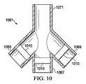
図10を参照すると、マルチパスコネクタ1061の例示的実施形態が示されている。マルチパスコネクタ1061は、マルチパスコネクタ961と同様であり、かつ第1の分岐ポート1065、第2の分岐ポート1067、第3の分岐ポート1069、および供給ポート1071を含む。分岐ポート1065、1067、1069の各々は減圧チューブに結合されるように適合されており、減圧チューブは、減圧ドレッシングに流体的に接続されている。供給ポート1071は、減圧源に流体的に接続されている供給チューブに結合されるように適合されている。マルチパスコネクタ1061は、複数のチューブまたは導管を接続する手段を提供し、流体および圧力の分配を生じ得る。図10に示すマルチパスコネクタ1061は、4つの導管またはチューブを流体的に接続できるが、その代わりに、より少数のチューブまたはより多数のチューブを接続するコネクタを設け得る。
Referring to FIG. 10, an exemplary embodiment of a
図10に示す実施形態では、分岐ポート1065、1067、1069の各々の内部に弁1010が配置される。マルチパスコネクタ1061の様々なポートに対する弁1010の配置は、様々とし得る;しかしながら、マルチパスコネクタ1061を通過するいずれの流体も、弁1010を通過して弁1010による制御を受ける必要があるように、弁1010を配置することが望ましい。弁1010は、マルチパスコネクタ1061に永久的にまたは取り外し可能に設置し得る。
In the embodiment shown in FIG. 10, a
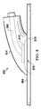
図11を参照すると、減圧送達チューブ1126の例示的実施形態が示されている。減圧送達チューブ1126は、減圧送達チューブ956と同様であり、かつ好ましくは、減圧源と減圧ドレッシングとの間に流体連通をもたらす。図11に示す実施形態では、弁1110は、減圧送達チューブ1126に動作可能に関連付けられる。チューブ内へのまたは単にそこに接続される弁1110の特定の配置は、様々とし得る;しかしながら、減圧送達チューブ1126を通るいずれの流体も、弁1110を通過して弁1110による制御を受ける必要があるように、弁1110を配置することが望ましい。弁1110は、減圧送達チューブ1126に永久的にまたは取り外し可能に設置し得る。
Referring to FIG. 11, an exemplary embodiment of a reduced
いくつもの別々の実施形態を説明したが、各実施形態の態様は、その実施形態にのみ特有のものではなく、および実施形態の特徴を他の実施形態の特徴と組み合わせ得ることを具体的に考慮する。 While several separate embodiments have been described, each aspect of each embodiment is not specific to that embodiment, and specifically considers that the features of the embodiments may be combined with the features of other embodiments. To do.
Claims (28)
前記組織部位の第1の組織部位に位置決めされるように適合された第1のドレッシング充填材と;
前記組織部位の第2の組織部位に位置決めされるように適合された第2のドレッシング充填材と;
前記第1のドレッシング充填材および前記第2のドレッシング充填材に流体的に接続されるように適合された減圧源と;
前記第1の組織部位に関連付けられて、前記第1の組織部位からの流体の流れを可能にしかつ前記第1の組織部位に向かう流体の流れを実質的に排除するように適合された第1の弁と;
前記第2の組織部位に関連付けられて、前記第2の組織部位からの流体の流れを可能にしかつ前記第2の組織部位に向かう流体の流れを実質的に排除するように適合された第2の弁と
を含み、
前記第1の弁および前記第2の弁が、各々、入口および出口と、前記入口と前記出口との間を流体連通させるように位置決めされた弁フラップおよびシールリングとを有し、前記弁フラップは、閉鎖位置と開放位置との間を可動であり、および前記閉鎖位置では、前記弁フラップは前記シールリングに接触して、前記入口と前記出口との間の流体連通を実質的に排除し、および開放位置では、前記弁フラップは前記シールリングから離れており、前記入口と前記出口との間の流体連通を可能にすることを特徴とする、システム。 In a system for treating multiple tissue sites,
A first dressing filler adapted to be positioned at a first tissue site of the tissue site;
A second dressing filler adapted to be positioned at a second tissue site of the tissue site;
A reduced pressure source adapted to be fluidly connected to the first dressing filler and the second dressing filler;
A first associated with the first tissue site and adapted to allow fluid flow from the first tissue site and substantially exclude fluid flow toward the first tissue site. And the valve;
A second, associated with the second tissue site, adapted to allow fluid flow from the second tissue site and substantially exclude fluid flow toward the second tissue site. look including a valve,
The first valve and the second valve each have an inlet and an outlet, and a valve flap and a seal ring positioned to provide fluid communication between the inlet and the outlet; Is movable between a closed position and an open position, and in the closed position, the valve flap contacts the seal ring, substantially eliminating fluid communication between the inlet and the outlet. And in the open position, the valve flap is remote from the seal ring to allow fluid communication between the inlet and the outlet .
内室を有する弁本体と;
前記内室と流体連通している入口と;
前記内室と流体連通している出口と;
前記内室の壁に配置されかつ前記入口の周囲を囲むシールリングと;
閉鎖位置と開放位置との間を可動な弁フラップであって、前記閉鎖位置では、前記弁フラップが前記シールリングと接触して、前記出口と前記入口との間の流体連通を実質的に防止し、および前記開放位置では、前記弁フラップは前記シールリングから離れており、前記入口と前記出口との間の流体連通を可能にする、弁フラップと
を含むことを特徴とする、弁。 In a treatment valve that regulates fluid flow at a tissue site,
A valve body having an inner chamber;
An inlet in fluid communication with the inner chamber;
An outlet in fluid communication with the inner chamber;
A seal ring disposed on the wall of the inner chamber and surrounding the periphery of the inlet;
A valve flap movable between a closed position and an open position, wherein the valve flap contacts the seal ring to substantially prevent fluid communication between the outlet and the inlet. And, in the open position, the valve flap is remote from the seal ring and includes a valve flap that allows fluid communication between the inlet and the outlet.
前記組織部位に位置決めされるように適合されたドレッシング充填材と;
前記ドレッシング充填材および前記組織部位に隣接して位置決めされるように適合されたカバーであって、前記カバーと前記組織部位との間に実質的な密閉空間を形成する、カバーと;
前記実質的な密閉空間と流体連通し、前記実質的な密閉空間に減圧をもたらすように適合された減圧源と;
前記ドレッシング充填材と前記減圧源との間を流体連通させて、前記組織部位からの流体の流れを可能にしかつ前記組織部位に向かう流体の流れを実質的に防止するように適合された弁と
を含み、
前記弁が、前記弁の入口と出口との間を流体連通させるように位置決めされた弁フラップおよびシールリングを有し、前記弁フラップは、閉鎖位置と開放位置との間を可動であり、および前記閉鎖位置では、前記弁フラップは前記シールリングに接触して、前記入口と前記出口との間の流体連通を実質的に排除し、および開放位置では、前記弁フラップは前記シールリングから離れており、前記入口と前記出口との間の流体連通を可能にすることを特徴とする、治療システム。 In a treatment system for treating a tissue site,
Dressing filler adapted to be positioned at the tissue site;
A cover adapted to be positioned adjacent to the dressing filler and the tissue site, the cover forming a substantially enclosed space between the cover and the tissue site;
A reduced pressure source in fluid communication with the substantially enclosed space and adapted to provide a reduced pressure to the substantially enclosed space;
A valve adapted to provide fluid communication between the dressing filler and the reduced pressure source to allow fluid flow from the tissue site and substantially prevent fluid flow toward the tissue site; only including,
The valve has a valve flap and a seal ring positioned to provide fluid communication between an inlet and an outlet of the valve, the valve flap being movable between a closed position and an open position; and In the closed position, the valve flap contacts the seal ring to substantially eliminate fluid communication between the inlet and the outlet, and in the open position, the valve flap moves away from the seal ring. A treatment system, characterized by allowing fluid communication between the inlet and the outlet .
前記組織部位の第1の組織部位に位置決めされるように適合された第1のドレッシング充填材と;
前記組織部位の第2の組織部位に位置決めされるように適合された第2のドレッシング充填材と;
前記第1のドレッシング充填材と前記第2のドレッシング充填材との間に流体連通をもたらすように適合された橋絡用マニホールドと;
前記橋絡用マニホールドによって前記第1のドレッシング充填材および前記第2のドレッシング充填材に流体的に接続されるように適合された減圧源と;
前記橋絡用マニホールドと前記第1のドレッシング充填材との間を流体連通させる第1の弁であって、前記第1のドレッシング充填材との流体連通が前記第1の弁によってもたらされる、第1の弁と;
前記橋絡用マニホールドと前記第2のドレッシング充填材との間を流体連通させる第2の弁であって、前記第2のドレッシング充填材との流体連通が前記第2の弁によってもたらされ、および前記第1の弁および前記第2の弁が、各々、入口および出口を有し、前記第1および前記第2の弁が、各々、前記入口から前記出口への流体連通をもたらしかつ前記出口から前記入口への流体連通を実質的に排除するように適合されており、および前記第1の弁の前記入口が、前記第1のドレッシング充填材の方に位置決めされ、および前記第2の弁の前記入口が、前記第2のドレッシング充填材の方に位置決めされている、第2の弁と
を含み、
前記第1の弁および前記第2の弁が、各々、前記入口と前記出口との間を流体連通させるように位置決めされた弁フラップおよびシールリングを有し、前記弁フラップは、閉鎖位置と開放位置との間を可動であり、および前記閉鎖位置では、前記弁フラップは前記シールリングに接触して、前記入口と前記出口との間の流体連通を実質的に排除し、および開放位置では、前記弁フラップは前記シールリングから離れており、前記入口と前記出口との間の流体連通を可能にすることを特徴とする、システム。 In a system for treating multiple tissue sites,
A first dressing filler adapted to be positioned at a first tissue site of the tissue site;
A second dressing filler adapted to be positioned at a second tissue site of the tissue site;
A bridging manifold adapted to provide fluid communication between the first dressing filler and the second dressing filler;
A reduced pressure source adapted to be fluidly connected to the first dressing filler and the second dressing filler by the bridging manifold;
A first valve in fluid communication between the bridging manifold and the first dressing filler, wherein fluid communication with the first dressing filler is provided by the first valve; One valve;
A second valve for fluid communication between the bridging manifold and the second dressing filler, wherein fluid communication with the second dressing filler is provided by the second valve; And the first valve and the second valve each have an inlet and an outlet, and the first and second valves each provide fluid communication from the inlet to the outlet and the outlet Adapted to substantially eliminate fluid communication from the inlet to the inlet, and the inlet of the first valve is positioned towards the first dressing filler, and the second valve It said inlet of said are positioned towards the second dressing filler, saw including a second valve,
The first valve and the second valve each have a valve flap and a seal ring positioned to provide fluid communication between the inlet and the outlet, the valve flap being in a closed position and an open position And in the closed position, the valve flap contacts the seal ring to substantially eliminate fluid communication between the inlet and the outlet, and in the open position, The system characterized in that the valve flap is remote from the seal ring and allows fluid communication between the inlet and the outlet .
Applications Claiming Priority (3)
| Application Number | Priority Date | Filing Date | Title |
|---|---|---|---|
| US201161563529P | 2011-11-23 | 2011-11-23 | |
| US61/563,529 | 2011-11-23 | ||
| PCT/US2012/065631 WO2013078095A2 (en) | 2011-11-23 | 2012-11-16 | Reduced pressure tissue treatment systems and methods having a reduced pressure dressing and associated valve |
Publications (3)
| Publication Number | Publication Date |
|---|---|
| JP2014533579A JP2014533579A (en) | 2014-12-15 |
| JP2014533579A5 JP2014533579A5 (en) | 2016-01-14 |
| JP6158209B2 true JP6158209B2 (en) | 2017-07-05 |
Family
ID=47279101
Family Applications (1)
| Application Number | Title | Priority Date | Filing Date |
|---|---|---|---|
| JP2014543511A Expired - Fee Related JP6158209B2 (en) | 2011-11-23 | 2012-11-16 | Reduced pressure tissue treatment system and method with reduced pressure dressing and associated valve |
Country Status (7)
| Country | Link |
|---|---|
| US (1) | US9981075B2 (en) |
| EP (2) | EP3219338A3 (en) |
| JP (1) | JP6158209B2 (en) |
| CN (1) | CN103917257B (en) |
| AU (1) | AU2012340921B2 (en) |
| CA (1) | CA2855743A1 (en) |
| WO (1) | WO2013078095A2 (en) |
Families Citing this family (38)
| Publication number | Priority date | Publication date | Assignee | Title |
|---|---|---|---|---|
| US10413450B2 (en) * | 2007-12-12 | 2019-09-17 | University Of Kansas | Barrier system to reduce the rates of infections |
| DE102010034292A1 (en) * | 2010-08-13 | 2012-02-16 | Paul Hartmann Ag | Connecting device for merging at least two line sections in a vacuum wound treatment system |
| CN104619360B (en) * | 2012-09-12 | 2019-08-16 | 凯希特许有限公司 | System and method for collecting exudate in decompression treatment |
| US9427503B2 (en) * | 2013-03-15 | 2016-08-30 | Corvivo Inc. | Cardiotomy suction tube system with multiple tips |
| WO2016006458A1 (en) * | 2014-07-08 | 2016-01-14 | 株式会社村田製作所 | Negative-pressure closure therapy device |
| AU2015292343B2 (en) * | 2014-07-24 | 2020-05-07 | Solventum Intellectual Properties Company | Combination fluid instillation and negative pressure dressing |
| CN104225770A (en) * | 2014-09-30 | 2014-12-24 | 昆山韦睿医疗科技有限公司 | Method for cooperation of multiple negative-pressure treatment devices and negative-pressure treatment system |
| WO2017019939A1 (en) | 2015-07-29 | 2017-02-02 | Innovative Therapies, Inc. | Wound therapy device pressure monitoring and control system |
| US11306224B2 (en) | 2015-08-31 | 2022-04-19 | 3M Innovative Properties Company | Articles comprising (meth)acrylate pressure-sensitive adhesive with enhanced adhesion to wet surfaces |
| EP3344206B1 (en) | 2015-08-31 | 2020-09-23 | 3M Innovative Properties Company | Negative pressure wound therapy dressings comprising (meth)acrylate pressure-sensitive adhesive with enhanced adhesion to wet surfaces |
| GB201519388D0 (en) * | 2015-11-03 | 2015-12-16 | I2R Medical Ltd | Connector |
| US11771820B2 (en) | 2016-03-04 | 2023-10-03 | Smith & Nephew Plc | Negative pressure wound therapy apparatus for post breast surgery wounds |
| US11413388B2 (en) * | 2016-05-24 | 2022-08-16 | Somavac Medical Solutions, Inc. | Portable device with disposable reservoir for collection of internal fluid after surgery from a plurality of sites simultaneously |
| US11577017B2 (en) | 2016-05-24 | 2023-02-14 | Somavac Medical Solutions, Inc. | Analytical method for controlled and measured internal fluid after surgery |
| EP3320926B1 (en) * | 2016-11-10 | 2023-03-01 | Mölnlycke Health Care AB | Connector device for a negative pressure wound therapy system |
| CN106581789B (en) * | 2016-12-12 | 2023-05-26 | 武汉维斯第医用科技股份有限公司 | External multi-pipeline converter for negative pressure closed drainage system |
| WO2018150263A1 (en) | 2017-02-15 | 2018-08-23 | Smith & Nephew Pte. Limited | Negative pressure wound therapy apparatuses and methods for using the same |
| JP2020508767A (en) * | 2017-02-28 | 2020-03-26 | ティージェイ スミス アンド ネフュー リミテッド | Multiple dressings negative pressure wound therapy system |
| EP3372257A1 (en) * | 2017-03-09 | 2018-09-12 | Mölnlycke Health Care AB | Negative pressure wound therapy assembly |
| GB2560365B (en) * | 2017-03-09 | 2021-10-20 | Brightwake Ltd | Improvements relating to apparatus negative pressure wound therapy |
| WO2018167199A1 (en) * | 2017-03-15 | 2018-09-20 | Smith & Nephew Plc | Multiple dressing negative pressure wound therapy system with calibrated leak paths |
| US11179512B2 (en) * | 2017-06-07 | 2021-11-23 | Kci Licensing, Inc. | Multi-layer wound filler for extended wear time |
| WO2018229008A1 (en) * | 2017-06-14 | 2018-12-20 | Smith & Nephew Plc | Negative pressure wound therapy apparatus |
| WO2019055176A1 (en) * | 2017-09-14 | 2019-03-21 | Kci Licensing, Inc. | Oxygen therapy with fluid removal |
| GB201813282D0 (en) * | 2018-08-15 | 2018-09-26 | Smith & Nephew | System for medical device activation and opertion |
| GB201804347D0 (en) | 2018-03-19 | 2018-05-02 | Smith & Nephew Inc | Securing control of settings of negative pressure wound therapy apparatuses and methods for using the same |
| MX2020010044A (en) * | 2018-03-26 | 2021-01-15 | Deroyal Ind Inc | Multi-lumen bridge for negative pressure wound therapy system. |
| CN108433747A (en) * | 2018-04-11 | 2018-08-24 | 中山大学中山眼科中心 | The harvester of suction type liquid sample |
| GB201806988D0 (en) | 2018-04-30 | 2018-06-13 | Quintanar Felix Clarence | Power source charging for negative pressure wound therapy apparatus |
| US11559619B2 (en) | 2018-04-30 | 2023-01-24 | Smith & Nephew Asia Pacific Pte. Limited | Systems and methods for controlling dual mode negative pressure wound therapy apparatus |
| GB201808438D0 (en) | 2018-05-23 | 2018-07-11 | Smith & Nephew | Systems and methods for determining blockages in a negative pressure wound therapy system |
| BR112021003541A2 (en) * | 2018-08-29 | 2021-05-18 | Aatru Medical, LLC | negative pressure treatment including mechanical and chemical pump |
| WO2020231360A1 (en) * | 2019-05-10 | 2020-11-19 | HOT, Semih | A two-way vacuum assisted closure system |
| US11484640B2 (en) | 2019-07-03 | 2022-11-01 | T.J.Smith And Nephew, Limited | Negative pressure wound therapy dressing recognition, wound status detection, and therapy adjustment |
| US11890237B2 (en) * | 2019-10-04 | 2024-02-06 | Covidien Lp | Outflow collection vessels, systems, and components thereof for hysteroscopic surgical procedures |
| MX2022010815A (en) * | 2020-03-03 | 2022-09-27 | Deroyal Ind Inc | Negative pressure wound therapy instillation system. |
| CN111282152A (en) * | 2020-04-03 | 2020-06-16 | 美药星(南京)制药有限公司 | Flow control valve for controlling liquid flow and flow velocity |
| WO2023079382A1 (en) * | 2021-11-05 | 2023-05-11 | Kci Manufacturing Unlimited Company | Negative pressure wound therapy dressing with isolated super absorbent |
Family Cites Families (134)
| Publication number | Priority date | Publication date | Assignee | Title |
|---|---|---|---|---|
| US1355846A (en) | 1920-02-06 | 1920-10-19 | David A Rannells | Medical appliance |
| US2547758A (en) | 1949-01-05 | 1951-04-03 | Wilmer B Keeling | Instrument for treating the male urethra |
| US2632443A (en) | 1949-04-18 | 1953-03-24 | Eleanor P Lesher | Surgical dressing |
| GB692578A (en) | 1949-09-13 | 1953-06-10 | Minnesota Mining & Mfg | Improvements in or relating to drape sheets for surgical use |
| US2682873A (en) | 1952-07-30 | 1954-07-06 | Johnson & Johnson | General purpose protective dressing |
| NL189176B (en) | 1956-07-13 | 1900-01-01 | Hisamitsu Pharmaceutical Co | PLASTER BASED ON A SYNTHETIC RUBBER. |
| US2969057A (en) | 1957-11-04 | 1961-01-24 | Brady Co W H | Nematodic swab |
| US3066672A (en) | 1960-09-27 | 1962-12-04 | Jr William H Crosby | Method and apparatus for serial sampling of intestinal juice |
| US3367332A (en) | 1965-08-27 | 1968-02-06 | Gen Electric | Product and process for establishing a sterile area of skin |
| US3520300A (en) | 1967-03-15 | 1970-07-14 | Amp Inc | Surgical sponge and suction device |
| US3568675A (en) | 1968-08-30 | 1971-03-09 | Clyde B Harvey | Fistula and penetrating wound dressing |
| US3682180A (en) | 1970-06-08 | 1972-08-08 | Coilform Co Inc | Drain clip for surgical drain |
| BE789293Q (en) | 1970-12-07 | 1973-01-15 | Parke Davis & Co | MEDICO-SURGICAL DRESSING FOR BURNS AND SIMILAR LESIONS |
| US3826254A (en) | 1973-02-26 | 1974-07-30 | Verco Ind | Needle or catheter retaining appliance |
| DE2527706A1 (en) | 1975-06-21 | 1976-12-30 | Hanfried Dr Med Weigand | DEVICE FOR THE INTRODUCTION OF CONTRAST AGENTS INTO AN ARTIFICIAL INTESTINAL OUTLET |
| DE2640413C3 (en) | 1976-09-08 | 1980-03-27 | Richard Wolf Gmbh, 7134 Knittlingen | Catheter monitor |
| NL7710909A (en) | 1976-10-08 | 1978-04-11 | Smith & Nephew | COMPOSITE STRAPS. |
| GB1562244A (en) | 1976-11-11 | 1980-03-05 | Lock P M | Wound dressing materials |
| US4080970A (en) | 1976-11-17 | 1978-03-28 | Miller Thomas J | Post-operative combination dressing and internal drain tube with external shield and tube connector |
| US4139004A (en) | 1977-02-17 | 1979-02-13 | Gonzalez Jr Harry | Bandage apparatus for treating burns |
| US4184510A (en) | 1977-03-15 | 1980-01-22 | Fibra-Sonics, Inc. | Valued device for controlling vacuum in surgery |
| US4165748A (en) | 1977-11-07 | 1979-08-28 | Johnson Melissa C | Catheter tube holder |
| US4245637A (en) | 1978-07-10 | 1981-01-20 | Nichols Robert L | Shutoff valve sleeve |
| SE414994B (en) | 1978-11-28 | 1980-09-01 | Landstingens Inkopscentral | VENKATETERFORBAND |
| GB2047543B (en) | 1978-12-06 | 1983-04-20 | Svedman Paul | Device for treating tissues for example skin |
| US4266545A (en) | 1979-04-06 | 1981-05-12 | Moss James P | Portable suction device for collecting fluids from a closed wound |
| US4284079A (en) | 1979-06-28 | 1981-08-18 | Adair Edwin Lloyd | Method for applying a male incontinence device |
| US4261363A (en) | 1979-11-09 | 1981-04-14 | C. R. Bard, Inc. | Retention clips for body fluid drains |
| US4569348A (en) | 1980-02-22 | 1986-02-11 | Velcro Usa Inc. | Catheter tube holder strap |
| US4480638A (en) | 1980-03-11 | 1984-11-06 | Eduard Schmid | Cushion for holding an element of grafted skin |
| US4297995A (en) | 1980-06-03 | 1981-11-03 | Key Pharmaceuticals, Inc. | Bandage containing attachment post |
| DE3024589C2 (en) * | 1980-06-28 | 1982-09-09 | Bopp & Reuther Gmbh, 6800 Mannheim | Butterfly valve |
| US4333468A (en) | 1980-08-18 | 1982-06-08 | Geist Robert W | Mesentery tube holder apparatus |
| US4465485A (en) | 1981-03-06 | 1984-08-14 | Becton, Dickinson And Company | Suction canister with unitary shut-off valve and filter features |
| US4392853A (en) | 1981-03-16 | 1983-07-12 | Rudolph Muto | Sterile assembly for protecting and fastening an indwelling device |
| US4373519A (en) | 1981-06-26 | 1983-02-15 | Minnesota Mining And Manufacturing Company | Composite wound dressing |
| US4392858A (en) | 1981-07-16 | 1983-07-12 | Sherwood Medical Company | Wound drainage device |
| US4419097A (en) | 1981-07-31 | 1983-12-06 | Rexar Industries, Inc. | Attachment for catheter tube |
| SE429197B (en) | 1981-10-14 | 1983-08-22 | Frese Nielsen | SAR TREATMENT DEVICE |
| DE3146266A1 (en) | 1981-11-21 | 1983-06-01 | B. Braun Melsungen Ag, 3508 Melsungen | COMBINED DEVICE FOR A MEDICAL SUCTION DRAINAGE |
| US4551139A (en) | 1982-02-08 | 1985-11-05 | Marion Laboratories, Inc. | Method and apparatus for burn wound treatment |
| US4475909A (en) | 1982-05-06 | 1984-10-09 | Eisenberg Melvin I | Male urinary device and method for applying the device |
| DE3361779D1 (en) | 1982-07-06 | 1986-02-20 | Dow Corning | Medical-surgical dressing and a process for the production thereof |
| US4493701A (en) * | 1982-08-19 | 1985-01-15 | American Hospital Supply Corporation | Wound drainage device of resilient sidewalls with a constant rate of recovery |
| NZ206837A (en) | 1983-01-27 | 1986-08-08 | Johnson & Johnson Prod Inc | Thin film adhesive dressing:backing material in three sections |
| US4548202A (en) | 1983-06-20 | 1985-10-22 | Ethicon, Inc. | Mesh tissue fasteners |
| US4540412A (en) | 1983-07-14 | 1985-09-10 | The Kendall Company | Device for moist heat therapy |
| US4543100A (en) | 1983-11-01 | 1985-09-24 | Brodsky Stuart A | Catheter and drain tube retainer |
| US4525374A (en) | 1984-02-27 | 1985-06-25 | Manresa, Inc. | Treating hydrophobic filters to render them hydrophilic |
| GB2157958A (en) | 1984-05-03 | 1985-11-06 | Ernest Edward Austen Bedding | Ball game net support |
| US4897081A (en) | 1984-05-25 | 1990-01-30 | Thermedics Inc. | Percutaneous access device |
| US5215522A (en) | 1984-07-23 | 1993-06-01 | Ballard Medical Products | Single use medical aspirating device and method |
| GB8419745D0 (en) | 1984-08-02 | 1984-09-05 | Smith & Nephew Ass | Wound dressing |
| US4872450A (en) | 1984-08-17 | 1989-10-10 | Austad Eric D | Wound dressing and method of forming same |
| US4655754A (en) | 1984-11-09 | 1987-04-07 | Stryker Corporation | Vacuum wound drainage system and lipids baffle therefor |
| US4826494A (en) | 1984-11-09 | 1989-05-02 | Stryker Corporation | Vacuum wound drainage system |
| US4605399A (en) | 1984-12-04 | 1986-08-12 | Complex, Inc. | Transdermal infusion device |
| US5037397A (en) | 1985-05-03 | 1991-08-06 | Medical Distributors, Inc. | Universal clamp |
| US4640688A (en) | 1985-08-23 | 1987-02-03 | Mentor Corporation | Urine collection catheter |
| US4710165A (en) | 1985-09-16 | 1987-12-01 | Mcneil Charles B | Wearable, variable rate suction/collection device |
| US4758220A (en) | 1985-09-26 | 1988-07-19 | Alcon Laboratories, Inc. | Surgical cassette proximity sensing and latching apparatus |
| US4733659A (en) | 1986-01-17 | 1988-03-29 | Seton Company | Foam bandage |
| WO1987004626A1 (en) | 1986-01-31 | 1987-08-13 | Osmond, Roger, L., W. | Suction system for wound and gastro-intestinal drainage |
| US4838883A (en) | 1986-03-07 | 1989-06-13 | Nissho Corporation | Urine-collecting device |
| JPS62281965A (en) | 1986-05-29 | 1987-12-07 | テルモ株式会社 | Catheter and catheter fixing member |
| GB8621884D0 (en) | 1986-09-11 | 1986-10-15 | Bard Ltd | Catheter applicator |
| GB2195255B (en) | 1986-09-30 | 1991-05-01 | Vacutec Uk Limited | Apparatus for vacuum treatment of an epidermal surface |
| US4743232A (en) | 1986-10-06 | 1988-05-10 | The Clinipad Corporation | Package assembly for plastic film bandage |
| DE3634569A1 (en) | 1986-10-10 | 1988-04-21 | Sachse Hans E | CONDOM CATHETER, A URINE TUBE CATHETER FOR PREVENTING RISING INFECTIONS |
| JPS63135179A (en) | 1986-11-26 | 1988-06-07 | 立花 俊郎 | Subcataneous drug administration set |
| GB8628564D0 (en) | 1986-11-28 | 1987-01-07 | Smiths Industries Plc | Anti-foaming agent suction apparatus |
| GB8706116D0 (en) | 1987-03-14 | 1987-04-15 | Smith & Nephew Ass | Adhesive dressings |
| US4787888A (en) | 1987-06-01 | 1988-11-29 | University Of Connecticut | Disposable piezoelectric polymer bandage for percutaneous delivery of drugs and method for such percutaneous delivery (a) |
| US4863449A (en) | 1987-07-06 | 1989-09-05 | Hollister Incorporated | Adhesive-lined elastic condom cathether |
| US5176663A (en) | 1987-12-02 | 1993-01-05 | Pal Svedman | Dressing having pad with compressibility limiting elements |
| US4906240A (en) | 1988-02-01 | 1990-03-06 | Matrix Medica, Inc. | Adhesive-faced porous absorbent sheet and method of making same |
| US4985019A (en) | 1988-03-11 | 1991-01-15 | Michelson Gary K | X-ray marker |
| GB8812803D0 (en) | 1988-05-28 | 1988-06-29 | Smiths Industries Plc | Medico-surgical containers |
| US4919654A (en) | 1988-08-03 | 1990-04-24 | Kalt Medical Corporation | IV clamp with membrane |
| US5000741A (en) | 1988-08-22 | 1991-03-19 | Kalt Medical Corporation | Transparent tracheostomy tube dressing |
| EP0379416B1 (en) | 1989-01-16 | 1995-03-08 | Roussel-Uclaf | Azabicycloheptene derivatives and their salts, process for their preparation, their use as medicaments and compositions containing them |
| GB8906100D0 (en) | 1989-03-16 | 1989-04-26 | Smith & Nephew | Laminates |
| US5100396A (en) | 1989-04-03 | 1992-03-31 | Zamierowski David S | Fluidic connection system and method |
| US5527293A (en) | 1989-04-03 | 1996-06-18 | Kinetic Concepts, Inc. | Fastening system and method |
| US4969880A (en) | 1989-04-03 | 1990-11-13 | Zamierowski David S | Wound dressing and treatment method |
| US5261893A (en) | 1989-04-03 | 1993-11-16 | Zamierowski David S | Fastening system and method |
| US5358494A (en) | 1989-07-11 | 1994-10-25 | Svedman Paul | Irrigation dressing |
| JP2719671B2 (en) | 1989-07-11 | 1998-02-25 | 日本ゼオン株式会社 | Wound dressing |
| US5232453A (en) | 1989-07-14 | 1993-08-03 | E. R. Squibb & Sons, Inc. | Catheter holder |
| GB2235877A (en) | 1989-09-18 | 1991-03-20 | Antonio Talluri | Closed wound suction apparatus |
| US5134994A (en) | 1990-02-12 | 1992-08-04 | Say Sam L | Field aspirator in a soft pack with externally mounted container |
| US5092858A (en) | 1990-03-20 | 1992-03-03 | Becton, Dickinson And Company | Liquid gelling agent distributor device |
| JP2941918B2 (en) | 1990-09-19 | 1999-08-30 | テルモ株式会社 | Weighing device |
| US5149331A (en) | 1991-05-03 | 1992-09-22 | Ariel Ferdman | Method and device for wound closure |
| US5278100A (en) | 1991-11-08 | 1994-01-11 | Micron Technology, Inc. | Chemical vapor deposition technique for depositing titanium silicide on semiconductor wafers |
| US5636643A (en) | 1991-11-14 | 1997-06-10 | Wake Forest University | Wound treatment employing reduced pressure |
| US5645081A (en) | 1991-11-14 | 1997-07-08 | Wake Forest University | Method of treating tissue damage and apparatus for same |
| US5279550A (en) | 1991-12-19 | 1994-01-18 | Gish Biomedical, Inc. | Orthopedic autotransfusion system |
| US5167613A (en) | 1992-03-23 | 1992-12-01 | The Kendall Company | Composite vented wound dressing |
| FR2690617B1 (en) | 1992-04-29 | 1994-06-24 | Cbh Textile | TRANSPARENT ADHESIVE DRESSING. |
| DE4306478A1 (en) | 1993-03-02 | 1994-09-08 | Wolfgang Dr Wagner | Drainage device, in particular pleural drainage device, and drainage method |
| US5342376A (en) | 1993-05-03 | 1994-08-30 | Dermagraphics, Inc. | Inserting device for a barbed tissue connector |
| US6241747B1 (en) | 1993-05-03 | 2001-06-05 | Quill Medical, Inc. | Barbed Bodily tissue connector |
| US5344415A (en) | 1993-06-15 | 1994-09-06 | Deroyal Industries, Inc. | Sterile system for dressing vascular access site |
| US5437651A (en) | 1993-09-01 | 1995-08-01 | Research Medical, Inc. | Medical suction apparatus |
| US5549584A (en) | 1994-02-14 | 1996-08-27 | The Kendall Company | Apparatus for removing fluid from a wound |
| US5556375A (en) | 1994-06-16 | 1996-09-17 | Hercules Incorporated | Wound dressing having a fenestrated base layer |
| US5607388A (en) | 1994-06-16 | 1997-03-04 | Hercules Incorporated | Multi-purpose wound dressing |
| US5664270A (en) | 1994-07-19 | 1997-09-09 | Kinetic Concepts, Inc. | Patient interface system |
| WO1996005873A1 (en) | 1994-08-22 | 1996-02-29 | Kinetic Concepts Inc. | Wound drainage equipment |
| DE29504378U1 (en) | 1995-03-15 | 1995-09-14 | Mtg Medizinisch Tech Geraeteba | Electronically controlled low-vacuum pump for chest and wound drainage |
| GB9523253D0 (en) | 1995-11-14 | 1996-01-17 | Mediscus Prod Ltd | Portable wound treatment apparatus |
| DE19545421C2 (en) * | 1995-12-06 | 2001-05-10 | Filtertek Bv | Check valve, especially for medical technology |
| US6135116A (en) | 1997-07-28 | 2000-10-24 | Kci Licensing, Inc. | Therapeutic method for treating ulcers |
| AU755496B2 (en) | 1997-09-12 | 2002-12-12 | Kci Licensing, Inc. | Surgical drape and suction head for wound treatment |
| GB9719520D0 (en) | 1997-09-12 | 1997-11-19 | Kci Medical Ltd | Surgical drape and suction heads for wound treatment |
| US6071267A (en) | 1998-02-06 | 2000-06-06 | Kinetic Concepts, Inc. | Medical patient fluid management interface system and method |
| US6488643B1 (en) | 1998-10-08 | 2002-12-03 | Kci Licensing, Inc. | Wound healing foot wrap |
| US6287316B1 (en) | 1999-03-26 | 2001-09-11 | Ethicon, Inc. | Knitted surgical mesh |
| US7799004B2 (en) | 2001-03-05 | 2010-09-21 | Kci Licensing, Inc. | Negative pressure wound treatment apparatus and infection identification system and method |
| US6856821B2 (en) | 2000-05-26 | 2005-02-15 | Kci Licensing, Inc. | System for combined transcutaneous blood gas monitoring and vacuum assisted wound closure |
| US6991643B2 (en) | 2000-12-20 | 2006-01-31 | Usgi Medical Inc. | Multi-barbed device for retaining tissue in apposition and methods of use |
| WO2001062328A1 (en) | 2000-02-24 | 2001-08-30 | Venetec International, Inc. | Universal catheter anchoring system |
| US6540705B2 (en) | 2001-02-22 | 2003-04-01 | Core Products International, Inc. | Ankle brace providing upper and lower ankle adjustment |
| DE102005007016A1 (en) * | 2005-02-15 | 2006-08-24 | Fleischmann, Wilhelm, Dr.med. | Device for the treatment of wounds |
| US20090157016A1 (en) | 2005-07-24 | 2009-06-18 | Carmeli Adahan | Suctioning system, method and kit |
| EP2127690B2 (en) * | 2005-07-24 | 2017-06-14 | M.E.A.C. Engineering Ltd. | Wound closure and drainage system |
| CA2661963A1 (en) * | 2006-08-30 | 2008-03-06 | Southeastern Medical Technologies | Methods, compositions and apparatuses to treat wounds with pressures altered from atmospheric |
| US20090281509A1 (en) * | 2008-05-12 | 2009-11-12 | Gellis Michael B | Apparatus to collect body fluids following liposuction surgery |
| WO2009141820A1 (en) | 2008-05-21 | 2009-11-26 | Morris Topaz | Wound healing device |
| WO2010102146A1 (en) | 2009-03-04 | 2010-09-10 | Spiracur Inc. | Devices and methods to apply alternating level of reduced pressure to tissue |
| GB2470940A (en) | 2009-06-10 | 2010-12-15 | Systagenix Wound Man Ip Co Bv | Vacuum wound dressing with hydrogel layer |
| TW201102116A (en) * | 2009-07-13 | 2011-01-16 | Univ Nat Pingtung Sci & Tech | A portable negative-bias caring device |
| US9452247B2 (en) * | 2009-12-16 | 2016-09-27 | Paul Hartmann Ag | Device for negative pressure wound therapy |
-
2012
- 2012-11-16 JP JP2014543511A patent/JP6158209B2/en not_active Expired - Fee Related
- 2012-11-16 US US13/679,865 patent/US9981075B2/en active Active
- 2012-11-16 WO PCT/US2012/065631 patent/WO2013078095A2/en active Application Filing
- 2012-11-16 CA CA 2855743 patent/CA2855743A1/en not_active Abandoned
- 2012-11-16 EP EP17168662.9A patent/EP3219338A3/en not_active Withdrawn
- 2012-11-16 CN CN201280055068.9A patent/CN103917257B/en not_active Expired - Fee Related
- 2012-11-16 AU AU2012340921A patent/AU2012340921B2/en not_active Ceased
- 2012-11-16 EP EP12795246.3A patent/EP2782614B1/en active Active
Also Published As
| Publication number | Publication date |
|---|---|
| CN103917257A (en) | 2014-07-09 |
| US9981075B2 (en) | 2018-05-29 |
| EP3219338A3 (en) | 2017-12-27 |
| CN103917257B (en) | 2019-02-15 |
| JP2014533579A (en) | 2014-12-15 |
| AU2012340921A1 (en) | 2014-05-01 |
| WO2013078095A3 (en) | 2013-07-18 |
| EP2782614A2 (en) | 2014-10-01 |
| EP2782614B1 (en) | 2017-05-03 |
| CA2855743A1 (en) | 2013-05-30 |
| AU2012340921B2 (en) | 2017-05-11 |
| WO2013078095A2 (en) | 2013-05-30 |
| US20130131616A1 (en) | 2013-05-23 |
| EP3219338A2 (en) | 2017-09-20 |
Similar Documents
| Publication | Publication Date | Title |
|---|---|---|
| JP6158209B2 (en) | Reduced pressure tissue treatment system and method with reduced pressure dressing and associated valve | |
| JP6707099B2 (en) | Abdominal treatment system, delivery device, and method | |
| US20230201042A1 (en) | Hybrid drape having a gel-coated perforated mesh | |
| JP6293824B2 (en) | Dressing and system providing decompression therapy | |
| EP3574877B1 (en) | Low-acuity dressing with integral pump | |
| JP6259510B2 (en) | Multi-porous conduit | |
| EP3294158B1 (en) | Wound debridement by irrigation with ultrasonically activated microbubbles | |
| CN102715984B (en) | Self contained wound dressing with micropump | |
| JP6306031B2 (en) | Wound connection pad with pneumatic connection confirmation capability | |
| JP5500603B2 (en) | System and method for delivering reduced pressure to subcutaneous tissue | |
| US8167869B2 (en) | Wound therapy system with proportional valve mechanism | |
| JP6189840B2 (en) | Decompression wound dressing | |
| JP2016221298A (en) | Dressings, systems and methods for treating tissue site | |
| KR20110083692A (en) | Modular, reduced-pressure, wound-closure systems and methods | |
| JP2017530755A (en) | Dynamic negative pressure therapy with infusion | |
| JP2012523915A (en) | Reduced pressure treatment system and method using variable cover |
Legal Events
| Date | Code | Title | Description |
|---|---|---|---|
| A521 | Request for written amendment filed |
Free format text: JAPANESE INTERMEDIATE CODE: A523 Effective date: 20151113 |
|
| A621 | Written request for application examination |
Free format text: JAPANESE INTERMEDIATE CODE: A621 Effective date: 20151113 |
|
| A131 | Notification of reasons for refusal |
Free format text: JAPANESE INTERMEDIATE CODE: A131 Effective date: 20160816 |
|
| A521 | Request for written amendment filed |
Free format text: JAPANESE INTERMEDIATE CODE: A523 Effective date: 20161116 |
|
| TRDD | Decision of grant or rejection written | ||
| A01 | Written decision to grant a patent or to grant a registration (utility model) |
Free format text: JAPANESE INTERMEDIATE CODE: A01 Effective date: 20170509 |
|
| A61 | First payment of annual fees (during grant procedure) |
Free format text: JAPANESE INTERMEDIATE CODE: A61 Effective date: 20170607 |
|
| R150 | Certificate of patent or registration of utility model |
Ref document number: 6158209 Country of ref document: JP Free format text: JAPANESE INTERMEDIATE CODE: R150 |
|
| R250 | Receipt of annual fees |
Free format text: JAPANESE INTERMEDIATE CODE: R250 |
|
| S111 | Request for change of ownership or part of ownership |
Free format text: JAPANESE INTERMEDIATE CODE: R313113 |
|
| R360 | Written notification for declining of transfer of rights |
Free format text: JAPANESE INTERMEDIATE CODE: R360 |
|
| R360 | Written notification for declining of transfer of rights |
Free format text: JAPANESE INTERMEDIATE CODE: R360 |
|
| R371 | Transfer withdrawn |
Free format text: JAPANESE INTERMEDIATE CODE: R371 |
|
| S111 | Request for change of ownership or part of ownership |
Free format text: JAPANESE INTERMEDIATE CODE: R313113 |
|
| LAPS | Cancellation because of no payment of annual fees | ||
| R350 | Written notification of registration of transfer |
Free format text: JAPANESE INTERMEDIATE CODE: R350 |