JP6107745B2 - Power conversion device and abnormality diagnosis method for power conversion device - Google Patents
Power conversion device and abnormality diagnosis method for power conversion device Download PDFInfo
- Publication number
- JP6107745B2 JP6107745B2 JP2014107190A JP2014107190A JP6107745B2 JP 6107745 B2 JP6107745 B2 JP 6107745B2 JP 2014107190 A JP2014107190 A JP 2014107190A JP 2014107190 A JP2014107190 A JP 2014107190A JP 6107745 B2 JP6107745 B2 JP 6107745B2
- Authority
- JP
- Japan
- Prior art keywords
- unit
- blocking
- command
- signal
- shut
- Prior art date
- Legal status (The legal status is an assumption and is not a legal conclusion. Google has not performed a legal analysis and makes no representation as to the accuracy of the status listed.)
- Active
Links
Images

Classifications
-
- H—ELECTRICITY
- H02—GENERATION; CONVERSION OR DISTRIBUTION OF ELECTRIC POWER
- H02M—APPARATUS FOR CONVERSION BETWEEN AC AND AC, BETWEEN AC AND DC, OR BETWEEN DC AND DC, AND FOR USE WITH MAINS OR SIMILAR POWER SUPPLY SYSTEMS; CONVERSION OF DC OR AC INPUT POWER INTO SURGE OUTPUT POWER; CONTROL OR REGULATION THEREOF
- H02M1/00—Details of apparatus for conversion
- H02M1/32—Means for protecting converters other than automatic disconnection
-
- H—ELECTRICITY
- H02—GENERATION; CONVERSION OR DISTRIBUTION OF ELECTRIC POWER
- H02H—EMERGENCY PROTECTIVE CIRCUIT ARRANGEMENTS
- H02H7/00—Emergency protective circuit arrangements specially adapted for specific types of electric machines or apparatus or for sectionalised protection of cable or line systems, and effecting automatic switching in the event of an undesired change from normal working conditions
- H02H7/08—Emergency protective circuit arrangements specially adapted for specific types of electric machines or apparatus or for sectionalised protection of cable or line systems, and effecting automatic switching in the event of an undesired change from normal working conditions for dynamo-electric motors
- H02H7/0833—Emergency protective circuit arrangements specially adapted for specific types of electric machines or apparatus or for sectionalised protection of cable or line systems, and effecting automatic switching in the event of an undesired change from normal working conditions for dynamo-electric motors for electric motors with control arrangements
- H02H7/0844—Fail safe control, e.g. by comparing control signal and controlled current, isolating motor on commutation error
-
- H—ELECTRICITY
- H02—GENERATION; CONVERSION OR DISTRIBUTION OF ELECTRIC POWER
- H02M—APPARATUS FOR CONVERSION BETWEEN AC AND AC, BETWEEN AC AND DC, OR BETWEEN DC AND DC, AND FOR USE WITH MAINS OR SIMILAR POWER SUPPLY SYSTEMS; CONVERSION OF DC OR AC INPUT POWER INTO SURGE OUTPUT POWER; CONTROL OR REGULATION THEREOF
- H02M5/00—Conversion of ac power input into ac power output, e.g. for change of voltage, for change of frequency, for change of number of phases
- H02M5/02—Conversion of ac power input into ac power output, e.g. for change of voltage, for change of frequency, for change of number of phases without intermediate conversion into dc
- H02M5/04—Conversion of ac power input into ac power output, e.g. for change of voltage, for change of frequency, for change of number of phases without intermediate conversion into dc by static converters
- H02M5/22—Conversion of ac power input into ac power output, e.g. for change of voltage, for change of frequency, for change of number of phases without intermediate conversion into dc by static converters using discharge tubes with control electrode or semiconductor devices with control electrode
- H02M5/275—Conversion of ac power input into ac power output, e.g. for change of voltage, for change of frequency, for change of number of phases without intermediate conversion into dc by static converters using discharge tubes with control electrode or semiconductor devices with control electrode using devices of a triode or transistor type requiring continuous application of a control signal
- H02M5/297—Conversion of ac power input into ac power output, e.g. for change of voltage, for change of frequency, for change of number of phases without intermediate conversion into dc by static converters using discharge tubes with control electrode or semiconductor devices with control electrode using devices of a triode or transistor type requiring continuous application of a control signal for conversion of frequency
-
- H—ELECTRICITY
- H02—GENERATION; CONVERSION OR DISTRIBUTION OF ELECTRIC POWER
- H02H—EMERGENCY PROTECTIVE CIRCUIT ARRANGEMENTS
- H02H3/00—Emergency protective circuit arrangements for automatic disconnection directly responsive to an undesired change from normal electric working condition with or without subsequent reconnection ; integrated protection
- H02H3/02—Details
- H02H3/05—Details with means for increasing reliability, e.g. redundancy arrangements
-
- H—ELECTRICITY
- H02—GENERATION; CONVERSION OR DISTRIBUTION OF ELECTRIC POWER
- H02H—EMERGENCY PROTECTIVE CIRCUIT ARRANGEMENTS
- H02H7/00—Emergency protective circuit arrangements specially adapted for specific types of electric machines or apparatus or for sectionalised protection of cable or line systems, and effecting automatic switching in the event of an undesired change from normal working conditions
- H02H7/10—Emergency protective circuit arrangements specially adapted for specific types of electric machines or apparatus or for sectionalised protection of cable or line systems, and effecting automatic switching in the event of an undesired change from normal working conditions for converters; for rectifiers
- H02H7/12—Emergency protective circuit arrangements specially adapted for specific types of electric machines or apparatus or for sectionalised protection of cable or line systems, and effecting automatic switching in the event of an undesired change from normal working conditions for converters; for rectifiers for static converters or rectifiers
- H02H7/1216—Emergency protective circuit arrangements specially adapted for specific types of electric machines or apparatus or for sectionalised protection of cable or line systems, and effecting automatic switching in the event of an undesired change from normal working conditions for converters; for rectifiers for static converters or rectifiers for AC-AC converters
Description
本開示は、電力変換装置、及び、電力変換装置の異常診断方法に関する。 The present disclosure relates to a power conversion device and an abnormality diagnosis method for the power conversion device.
例えば、インバータ等を用いて電力変換を行って交流電力を生成する電力変換装置があり、この種の電力変換装置はしばしば、モータを駆動するために用いられる。特許文献1には、この種の電力変換装置として、インバータを用いて直流電力から交流電力を生成するモータ制御装置が記載されている。 For example, there is a power conversion device that generates AC power by performing power conversion using an inverter or the like, and this type of power conversion device is often used to drive a motor. Patent Document 1 describes a motor control device that generates AC power from DC power using an inverter as this type of power conversion device.
特許文献1に記載のモータ制御装置は、インバータを駆動するゲート駆動回路と、ゲート駆動回路に与えるPWM(Pulse Width Modulation)信号を生成するPWM発生回路と、ゲート駆動回路とPWM発生回路との間に直列に接続された2つの3ステートバッファとを備え、これらの3ステートバッファのゲートの開閉は、外部の2つの停止スイッチとそれぞれ連動する。このモータ制御装置によれば、外部の2つの停止スイッチによって2つの3ステートバッファのゲートを閉じ、ゲート駆動回路へのPWM信号の供給を遮断し、インバータを停止し、モータを停止することができる。これにより、従来、モータとインバータとの間に設けていたコンタクタ(Electromagnetic Contactor)を省略でき、省スペース化を実現し、システムトータルコストを削減できる。また、停止スイッチ及び3ステートバッファによる安全停止回路の二重化によって、安全性を高めることができる。 A motor control device described in Patent Document 1 includes a gate drive circuit that drives an inverter, a PWM generation circuit that generates a PWM (Pulse Width Modulation) signal applied to the gate drive circuit, and a gate drive circuit and a PWM generation circuit. Are connected in series, and the opening and closing of the gates of these three-state buffers are interlocked with two external stop switches, respectively. According to this motor control device, the gates of the two three-state buffers are closed by two external stop switches, the supply of the PWM signal to the gate drive circuit is shut off, the inverter is stopped, and the motor can be stopped. . Thereby, the contactor (Electromagnetic Contactor) conventionally provided between the motor and the inverter can be omitted, space saving can be realized, and the total system cost can be reduced. Further, the safety can be improved by duplicating the safety stop circuit by the stop switch and the 3-state buffer.
また、このモータ制御装置は、3ステートバッファの異常状態を示す信号の論理積を生成する。これにより、外部の上位装置によって安全停止回路自体の異常状態を検出することができ、安全性をより高めることができる。 In addition, the motor control device generates a logical product of signals indicating an abnormal state of the 3-state buffer. Thereby, the abnormal state of the safety stop circuit itself can be detected by the external host device, and the safety can be further improved.
本開示は、従来に比して更に安全性を高めることができる電力変換装置、及び、電力変換装置の異常診断方法を提供することを目的とする。 An object of this indication is to provide the power converter device which can improve safety | security further compared with the past, and the abnormality diagnosis method of a power converter device.
本開示の電力変換装置は、交流電力を、周波数が異なる交流電力に直接変換する電力変換部と、電力変換部を駆動するゲート駆動部と、ゲート駆動部に供給するゲート駆動信号を生成するゲート駆動信号発生部と、ゲート駆動部とゲート駆動信号発生部との間に接続され、外部の上位装置からの指令に応じてゲート駆動部へのゲート駆動信号の供給及び遮断を切り換える2つの遮断部と、2つの遮断部のうちの少なくとも一方の遮断部の異常状態を診断する診断部と、診断部によって一方の遮断部が異常状態であると診断された場合に、2つの遮断部のうちの他方の遮断部に、ゲート駆動部へのゲート駆動信号の供給を遮断させる遮断制御部とを備え、一方の遮断部は、出力信号と関連したフィードバック信号を生成し、診断部は、指令とフィードバック信号とに基づいて、一方の遮断部の異常状態を診断する。 A power converter according to the present disclosure includes a power converter that directly converts AC power into AC power having a different frequency, a gate driver that drives the power converter, and a gate that generates a gate drive signal to be supplied to the gate driver. Drive signal generating unit, and two blocking units connected between the gate driving unit and the gate driving signal generating unit, which switch supply and blocking of the gate driving signal to the gate driving unit in accordance with a command from an external host device And a diagnostic unit for diagnosing an abnormal state of at least one of the two blocking units, and when the diagnostic unit diagnoses that one of the blocking units is in an abnormal state, The other shut-off unit includes a shut-off control unit that shuts off the supply of the gate drive signal to the gate drive unit. One shut-off unit generates a feedback signal related to the output signal, and the diagnosis unit sends the command and Based on the readback signal, to diagnose the abnormal condition of one of the cut-off portion.
また、本開示の電力変換装置の異常診断方法は、交流電力を、周波数が異なる交流電力に直接変換する電力変換部と、電力変換部を駆動するゲート駆動部と、ゲート駆動部に供給するゲート駆動信号を生成するゲート駆動信号発生部と、ゲート駆動部とゲート駆動信号発生部との間に接続され、外部の上位装置からの指令に応じてゲート駆動部へのゲート駆動信号の供給及び遮断を切り換える2つの遮断部とを備える電力変換装置の異常診断方法であって、2つの遮断部のうちの少なくとも一方の遮断部の異常状態を、前記一方の遮断部からの出力信号と関連したフィードバック信号と前記指令とに基づいて診断し、一方の遮断部が異常状態であると診断された場合に、2つの遮断部のうちの他方の遮断部に、ゲート駆動部へのゲート駆動信号の供給を遮断させる。 In addition, the abnormality diagnosis method for the power conversion device according to the present disclosure includes a power conversion unit that directly converts AC power into AC power having a different frequency, a gate drive unit that drives the power conversion unit, and a gate that is supplied to the gate drive unit. A gate drive signal generation unit that generates a drive signal, and is connected between the gate drive unit and the gate drive signal generation unit, and supplies and cuts off the gate drive signal to the gate drive unit according to a command from an external host device A method for diagnosing abnormality of a power conversion device comprising two shut-off units that switch between the two shut-off units, wherein an abnormal state of at least one of the shut-off units is related to an output signal from the one shut-off unit When a diagnosis is made based on the signal and the command, and one of the shut-off parts is diagnosed as being in an abnormal state, the other shut-off part of the two shut-off parts is connected to the gate drive signal to the gate drive part. To cut off the supply of.
また、本開示の電力変換装置は、交流電力を、周波数が異なる交流電力に直接変換する電力変換回路と、電力変換回路を駆動するゲート駆動回路と、ゲート駆動回路に供給するゲート駆動信号を生成するゲート駆動信号発生回路と、ゲート駆動回路とゲート駆動信号発生回路との間に直列に接続され、外部の上位装置からの指令に応じてゲート駆動回路へのゲート駆動信号の供給及び遮断を切り換える2つの遮断回路(ゲートバッファ)と、2つの遮断回路のうちの少なくとも一方の遮断回路の異常状態を診断する診断手段(診断回路)と、診断手段によって一方の遮断回路が異常状態であると診断された場合に、2つの遮断回路のうちの他方の遮断回路に、ゲート駆動回路へのゲート駆動信号の供給を遮断させる遮断制御手段(遮断制御回路)とを備え、一方の遮断回路は、出力信号と関連したフィードバック信号を生成し、診断手段は、指令とフィードバック信号とに基づいて、一方の遮断回路の異常状態を診断してもよい。 In addition, the power conversion device of the present disclosure generates a power conversion circuit that directly converts AC power into AC power having a different frequency, a gate drive circuit that drives the power conversion circuit, and a gate drive signal that is supplied to the gate drive circuit Connected in series between the gate drive signal generating circuit and the gate drive signal generating circuit, and switching between supply and cutoff of the gate drive signal to the gate drive circuit according to a command from an external host device Diagnosis means (diagnostic circuit) for diagnosing an abnormal state of at least one of the two cutoff circuits (gate buffer), a diagnostic circuit (diagnostic circuit), and diagnoses that one of the cutoff circuits is in an abnormal state by the diagnostic means In this case, the other cutoff circuit of the two cutoff circuits shuts off the supply of the gate drive signal to the gate drive circuit (the cutoff control circuit). ) And provided with, one of the blocking circuit generates a feedback signal related to the output signal, the diagnostic means based on a command and a feedback signal and may diagnose an abnormal state of one of the shutoff circuit.
本開示によれば、従来に比して更に安全性を高めることができる。 According to the present disclosure, it is possible to further improve safety as compared with the related art.
以下、図面を参照して実施形態について詳細に説明する。なお、各図面において同一又は相当の部分に対しては同一の符号を附すこととする。 Hereinafter, embodiments will be described in detail with reference to the drawings. In the drawings, the same or corresponding parts are denoted by the same reference numerals.
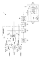
図1は、一実施形態に係る電力変換装置を示す回路ブロック図である。図1に示す電力変換装置1は、電力変換部(電力変換回路)10と、PWM発生部(PWM発生回路、ゲート駆動信号発生部、ゲート駆動信号発生回路)20と、ゲート駆動部(ゲート駆動回路)30と、2つの遮断部(遮断回路、ゲートバッファ)40,50と、診断部(診断手段、診断回路)60と、遮断制御部(遮断制御手段、遮断制御回路)70と、フォトカプラ41,51,61とを備える。
FIG. 1 is a circuit block diagram showing a power conversion device according to an embodiment. A power conversion device 1 illustrated in FIG. 1 includes a power conversion unit (power conversion circuit) 10, a PWM generation unit (PWM generation circuit, a gate drive signal generation unit, a gate drive signal generation circuit) 20, and a gate drive unit (gate drive). Circuit) 30, two shut-off parts (shut-off circuit, gate buffer) 40, 50, a diagnosis part (diagnosis means, diagnosis circuit) 60, a shut-off control part (shut-off control means, shut-off control circuit) 70, and a
電力変換部10は、複数のスイッチング素子を含み、交流電力を、周波数が異なる交流電力に直接変換する。例えば、三相交流モータを駆動するために、三相交流電力を、周波数が異なる三相交流電力に直接変換する場合、電力変換部10はマトリクスコンバータ回路(サイクロコンバータ回路)を含む。マトリクスコンバータ回路は、三相交流電源と三相交流モータとの間に9個の双方向スイッチを含む。まず、3個の双方向スイッチの一端は三相交流電源のU相、V相、W相にそれぞれ接続され、当該3個の双方向スイッチの他端は三相交流モータのU相に接続される。また、別の3個の双方向スイッチの一端は三相交流電源のU相、V相、W相にそれぞれ接続され、当該3個の双方向スイッチの他端は三相交流モータのV相に接続される。また、残りの3個の双方向スイッチの一端は三相交流電源のU相、V相、W相にそれぞれ接続され、当該3個の双方向スイッチの他端は三相交流モータのW相に接続される。そして、9個の双方向スイッチはそれぞれ、2つのスイッチング素子から構成される。すなわち、電力変換部10は、18個のスイッチング素子を含むこととなる。これらのスイッチング素子の一例としては、FET(Field effect transistor)やIGBT(Insulated GateBipolar Transistor)等が挙げられる。電力変換部10は、PWM発生部20及びゲート駆動部30によって駆動される。
The
PWM発生部20は、外部の上位装置からの指令(例えば、後述するHWBB1,HWBB2)に基づいて、電力変換部10を駆動するためのPWM(Pulse Width Modulation)信号を生成する。例えば、PWM発生部20は、電力変換部10における18個のスイッチング素子それぞれのために、6つのPWM信号を生成する。PWM発生部20は、PWM信号をゲート駆動部30に供給する。また、PWM発生部20は、外部の上位装置からの指令に応じて、ゲート駆動部30へのPWM信号の供給を停止する。
The
ゲート駆動部30は、PWM発生部20からのPWM信号に基づいて、電力変換部10を駆動するための駆動信号を生成する。例えば、ゲート駆動部30は、PWM発生部20からの6つのPWM信号に基づいて、電力変換部10における18個のスイッチング素子を駆動するための18個の駆動信号をそれぞれ生成する。PWM発生部20とゲート駆動部30との間には、2つの遮断部40,50が直列に接続されている。
Based on the PWM signal from the
遮断部40,50はそれぞれ、外部の上位装置からの指令HWBB1,HWBB2に応じて、PWM発生部20からゲート駆動部30へのPWM信号の供給及び遮断を切り換える。例えば、遮断部40,50はそれぞれ、6つのPWM信号のために6つの3ステートバッファを含む。指令HWBB1,HWBB2はそれぞれ、フォトカプラ41,51を介して遮断部40,50のイネーブル端子に入力される。
The shut-off
ここで、指令HWBB1,HWBB2は、モータを停止するために電力変換部10への駆動信号の供給を停止する指令、すなわち、PWM発生部20からゲート駆動部30へのPWM信号の供給を遮断する指令である。指令HWBB1,HWBB2は、ノーマリオン信号を含み、例えば、モータを動作するときにはLowレベルであり、モータを停止するときにHighレベルとなる。指令HWBB1,HWBB2は、特許文献1に記載の2つの停止スイッチそれぞれからの信号を含んでもよい。
Here, the commands HWBB1 and HWBB2 are commands for stopping the supply of the drive signal to the
例えば、指令HWBB1が動作を示すLowレベルである場合、フォトカプラ41がオン状態となり、遮断部40のイネーブル端子にLowレベルの動作指令HWBB1が入力される。すると、このLowレベルの動作指令HWBB1に応じて3ステートバッファのゲートが開き、遮断部40は、PWM発生部20からのPWM信号を遮断部50に供給する。同様に、指令HWBB2が動作を示すLowレベルである場合、フォトカプラ51がオン状態となり、遮断部50のイネーブル端子にLowレベルの動作指令HWBB2が入力される。すると、このLowレベルの動作指令HWBB2に応じて3ステートバッファのゲートが開き、遮断部50は、遮断部40からのPWM信号をゲート駆動部30に供給する。
For example, when the command HWBB1 is at the low level indicating the operation, the
一方、指令HWBB1が停止を示すHighレベルである場合、フォトカプラ41がオフ状態となり、遮断部40のイネーブル端子にHighレベルの停止指令HWBB1が入力される。すると、このHighレベルの停止指令HWBB1に応じて3ステートバッファのゲートが閉じて、3ステートバッファの出力がハイインピーダンスとなり、遮断部40は、PWM発生部20から遮断部50へのPWM信号の供給を遮断する。同様に、指令HWBB2が停止を示すHighレベルである場合、フォトカプラ51がオフ状態となり、遮断部50のイネーブル端子にHighレベルの停止指令HWBB2が入力される。すると、このHighレベルの停止指令HWBB2に応じて3ステートバッファのゲートが閉じて、3ステートバッファの出力がハイインピーダンスとなり、遮断部50は、遮断部40からゲート駆動部30へのPWM信号の供給を遮断する。これにより、特許文献1同様に、遮断部40,50による安全停止回路の二重化によって、安全性を高めることができる。
On the other hand, when the command HWBB1 is at a high level indicating a stop, the
また、遮断部40,50はそれぞれ、自身の正常状態及び異常状態を示す情報として、自身の出力信号に関連したフィードバック信号FB1,FB2を診断部60に供給する。例えば、遮断部40,50が正常状態である場合、フィードバック信号FB1,FB2は、Lowレベルである。一方、遮断部40,50が異常状態である場合には、フィードバック信号FB1,FB2は、Highレベルとなる。
Moreover, the interruption | blocking
診断部60は、外部の上位装置からの指令HWBB1と、遮断部40からのフィードバック信号FB1とに基づいて、遮断部40の正常状態及び異常状態を診断する。また、診断部60は、外部の上位装置からの指令HWBB2と、遮断部50からのフィードバック信号FB2とに基づいて、遮断部50の正常状態及び異常状態を診断する。診断部60は、遮断部40,50のうちの何れか一方が異常状態であると診断した場合、遮断制御部70に通知する。
The
診断部60は、CPU(Central Processing Unit)、ROM(Read Only Memory)、RAM(Random AccessMemory)等を含み、ROMに記憶されているプログラムをCPUで実行することによって構成される。
The
診断部60は、指令HWBB1が動作を示すLowレベルである場合、Lowレベルの動作指令HWBB1を遮断部40に供給するように、Lowレベルの信号SO1を遮断制御部70に通知するようにプログラムされ、構成されている。また、診断部60は、指令HWBB2が動作を示すLowレベルである場合、Lowレベルの動作指令HWBB2を遮断部50に供給するように、Lowレベルの信号SO2を遮断制御部70に通知するようにプログラムされ、構成されている。
The
また、診断部60は、指令HWBB1が動作を示すLowレベルである場合、フィードバック信号FB1がLowレベルであれば、遮断部40が正常状態であると診断し、遮断制御部70へのLowレベルの信号SO2の供給を継続するようにプログラムされ、構成されている。同様に、診断部60は、指令HWBB2が動作を示すLowレベルである場合、フィードバック信号FB2がLowレベルであれば、遮断部50が正常状態であると診断し、遮断制御部70へのLowレベルの信号SO1の供給を継続するようにプログラムされ、構成されている。
The
一方、指令HWBB1が動作を示すLowレベルである場合に、フィードバック信号FB1がHighレベルならば、診断部60は、遮断部40が異常状態であると診断し、異常を示すHighレベルの信号SO2にて遮断制御部70に通知するようにプログラムされ、構成されている。同様に、指令HWBB2が動作を示すLowレベルである場合、フィードバック信号FB2がHighレベルならば、診断部60は、遮断部50が異常状態であると診断し、異常を示すHighレベルの信号SO1にて遮断制御部70に通知するようにプログラムされ、構成されている。
On the other hand, when the command HWBB1 is at a low level indicating an operation and the feedback signal FB1 is at a high level, the
また、診断部60は、遮断部40,50の異常状態を示す信号の論理積信号EDMを生成するようにプログラムされ、構成されている。信号EDMは、フォトカプラ61を介して外部の上位装置へ供給される(EDM監視)。これにより、特許文献1同様に、外部の上位装置によって安全停止回路自体の異常状態を検出することができ、安全性を高めることができる。
The
遮断制御部70は、診断部60によって一方の遮断部40が異常状態であると診断された場合、他方の遮断部50への指令HWBB2の供給を遮断する。一方、遮断制御部70は、診断部60によって一方の遮断部50が異常状態であると診断された場合、他方の遮断部40への指令HWBB1の供給を遮断する。
When the
例えば、遮断制御部70は、遮断部40,50のイネーブル端子に対してそれぞれ直列に介在する2つのトランジスタ71,72を含む。トランジスタ71のコレクタは遮断部40のイネーブル端子に接続され、エミッタにはフォトカプラ41を介して指令HWBB1が入力され、ベースには診断部60からの信号SO1が入力される。一方、トランジスタ72のコレクタは遮断部50のイネーブル端子に接続され、エミッタにはフォトカプラ51を介して指令HWBB2が入力され、ベースには診断部60からの信号SO2が入力される。
For example, the
例えば、遮断制御部70におけるトランジスタ71は、診断部60からLowレベルの信号SO1を受けてオン状態となり、指令HWBB1を遮断部40に供給する。また、遮断制御部70におけるトランジスタ72は、診断部60からLowレベルの信号SO2を受けてオン状態となり、指令HWBB2を遮断部50に供給する。
For example, the
一方、遮断制御部70におけるトランジスタ71は、診断部60から遮断部50の異常を示すHighレベルの信号SO1を受けてオフ状態となり、遮断部40への指令HWBB1の供給を遮断する。また、遮断制御部70におけるトランジスタ72は、診断部60から遮断部40の異常を示すHighレベルの信号SO2を受けてオフ状態となり、遮断部50への指令HWBB2の供給を遮断する。
On the other hand, the
次に、電力変換装置の動作、及び、異常診断方法を示す。まず、Lowレベルの動作指令HWBB1,HWBB2が入力されると、診断部60からの信号SO1,SO2がLowレベルとなり、遮断制御部70におけるトランジスタ71,72がオン状態となり、遮断部40,50にLowレベルの動作指令HWBB1,HWBB2が供給される。
Next, the operation of the power converter and the abnormality diagnosis method will be shown. First, when the low level operation commands HWBB1 and HWBB2 are input, the signals SO1 and SO2 from the
遮断部40,50が正常状態である場合、遮断部40,50における3ステートバッファのゲートが開き、PWM発生部20からゲート駆動部30へPWM信号が供給される。このとき、遮断部40,50のフィードバック信号FB1,FB2がLowレベルとなる。すると、診断部60によって、Lowレベルの動作指令HWBB1,HWBB2とLowレベルのフィードバック信号FB1,FB2とに基づいて遮断部40,50が正常状態であると診断し、信号SO1,SO2をLowレベルのままとする。すると、遮断制御部70によって、遮断部40,50にLowレベルの動作指令HWBB1,HWBB2を供給し続け、遮断部40,50によって、PWM発生部20からゲート駆動部30へのPWM信号の供給が継続される。
When the blocking
一方、例えば、遮断部40が異常状態となると、遮断部40のフィードバック信号FB1がHighレベルとなる。すると、診断部60によって、Lowレベルの動作指令HWBB1とHighレベルのフィードバック信号FB1とに基づいて遮断部40が異常状態であると診断し、異常を示すHighレベルの信号SO2にて遮断制御部70に通知する。すると、遮断制御部70におけるトランジスタ72がオフ状態となり、遮断制御部70によって、遮断部50への指令HWBB2の供給を遮断する。すると、正常状態であるもう一方の遮断部50によって、PWM発生部20からゲート駆動部30へのPWM信号の供給を遮断することができる。
On the other hand, for example, when the blocking
また、例えば、遮断部50が異常状態となると、遮断部50のフィードバック信号FB2がHighレベルとなる。すると、診断部60によって、Lowレベルの動作指令HWBB2とHighレベルのフィードバック信号FB2とに基づいて遮断部50が異常状態であると診断し、異常を示すHighレベルの信号SO1にて遮断制御部70に通知する。すると、遮断制御部70におけるトランジスタ71がオフ状態となり、遮断制御部70によって、遮断部40への指令HWBB1の供給を遮断する。すると、正常状態であるもう一方の遮断部40によって、PWM発生部20からゲート駆動部30へのPWM信号の供給を遮断することができる。
Further, for example, when the blocking
この実施形態の電力変換装置によれば、2つの遮断部40,50のうちの少なくとも一方の遮断部の異常状態を診断する診断部60と、診断部60によって一方の遮断部が異常状態であると診断された場合に、2つの遮断部40,50のうちの他方の遮断部に、ゲート駆動部30へのPWM信号の供給を遮断させる遮断制御部70とを内蔵するので、外部の上位装置を介さずに安全停止回路としての遮断部40,50自体の異常状態を診断、一方の遮断部が異常状態である場合に、正常状態である他方の遮断部を遮断制御することができ、安全性をより高めることができる。
According to the power conversion device of this embodiment, a
ところで、欧州エレベータ安全規格によれば、モータと電力変換装置との間のコンタクタ(ElectromagneticContactor)を省略するためには、安全規格IEC61508のSIL3レベル相当であることが要求されている。一方、特許文献1に記載のモータ制御装置は、安全規格IEC61508のSIL2レベル相当であり、欧州向けエレベータに用いられる場合、コンタクタ(Electromagnetic Contactor)を省略できず、欧州向けエレベータの小型化、低コスト化が実現できなかった。しかしながら、この実施形態の電力変換装置は、安全規格IEC61508のSIL3レベル相当であるので、欧州向けエレベータに用いられる場合、コンタクタ(Electromagnetic Contactor)を省略でき、欧州向けエレベータの小型化、低コスト化が可能である。 By the way, according to the European elevator safety standard, in order to omit the contactor (Electromagnetic Contactor) between the motor and the power converter, it is required to be equivalent to the SIL3 level of the safety standard IEC61508. On the other hand, the motor control device described in Patent Document 1 corresponds to the SIL2 level of the safety standard IEC61508, and when used in an elevator for Europe, a contactor (Electromagnetic Contactor) cannot be omitted, and the size and cost of the elevator for Europe are reduced. Could not be realized. However, since the power converter of this embodiment is equivalent to the SIL3 level of the safety standard IEC61508, when used in an elevator for Europe, a contactor (Electromagnetic Contactor) can be omitted, and the size and cost of the elevator for Europe can be reduced. Is possible.
また、この実施形態では、2つの遮断部40,50のうちの何れか一方の遮断部が、出力信号と関連したフィードバック信号を生成し、診断部60が、指令と当該一方の遮断部からのフィードバック信号とに基づいて、当該一方の遮断部の異常状態を診断してもよい。この場合、診断部60は、当該一方の遮断部が異常状態であると診断した場合に、遮断制御部70に通知し、遮断制御部70は、診断部60からの通知に応じて2つの遮断部40,50のうちの他方の遮断部への指令の供給を遮断することによって、他方の遮断部に、ゲート駆動部30へのPWM信号の供給を遮断させてもよい。
In this embodiment, either one of the two blocking
また、この実施形態では、上述したように、2つの遮断部40,50の両方が、出力信号と関連したフィードバック信号を生成し、診断部60が、指令HWBB1,HWBB2と2つの遮断部40,50からのフィードバック信号FB1,FB2とに基づいて、2つの遮断部40,50の両方の異常状態を診断してもよい。この場合、診断部60は、2つの遮断部40,50のうちの何れか一方の遮断部が異常状態であると診断した場合に、遮断制御部70に通知し、遮断制御部70は、診断部60からの通知SO1,SO2に応じて2つの遮断部40,50のうちの他方の遮断部への指令の供給を遮断することによって、他方の遮断部に、ゲート駆動部30へのPWM信号の供給を遮断させてもよい。
In this embodiment, as described above, both of the two blocking
また、図2に、別の実施形態に係る電力変換装置の回路ブロック図を示す。図2に示す電力変換装置1Aは、電力変換装置1において、遮断部40に代えて遮断部40Aを備える点で本実施形態と異なっている。電力変換装置1Aの他の構成は、電力変換装置1と同一である。
FIG. 2 shows a circuit block diagram of a power conversion device according to another embodiment. A
遮断部40Aは、例えば、6つのPWM信号のために6つのフォトカプラを含む。また、遮断部40Aは、6つのフォトカプラへの電源電圧の供給及び遮断を切り換えるシャットオフ回路42を含み、シャットオフ回路42はトランジスタを含む。例えば、遮断制御部70からLowレベルの指令HWBB1が供給される場合、シャットオフ回路42におけるトランジスタがオン状態となり、シャットオフ回路42はフォトカプラに電源電力Vccを供給し、フォトカプラがオン状態となり、PWM発生部20からゲート駆動部30へPWM信号が供給される。一方、例えば、遮断制御部70からHighレベルの指令HWBB1が供給される場合、シャットオフ回路42におけるトランジスタがオフ状態となり、シャットオフ回路42はフォトカプラへの電源電力Vccの供給を遮断し、フォトカプラがオフ状態となり、PWM発生部20からゲート駆動部30へのPWM信号の供給が遮断される。
The blocking
また、遮断部50が異常状態となり、遮断制御部70からLowレベルの指令HWBB1の供給が遮断されると、シャットオフ回路42におけるトランジスタがオフ状態となり、シャットオフ回路42はフォトカプラへの電源電力Vccの供給を遮断し、フォトカプラがオフ状態となり、PWM発生部20からゲート駆動部30へのPWM信号の供給が遮断される。このように、遮断部40Aは、遮断制御部70からLowレベルの指令HWBB1の供給が遮断されると、シャットオフ回路42によってフォトカプラへの電源電力Vccの供給を遮断し、PWM発生部20からゲート駆動部30へのPWM信号の供給を遮断する。
When the shut-off
また、遮断部40Aは、シャットオフ回路42の異常状態をフィードバック信号FB1によって診断部60に通知してもよい。この場合、診断部60は、シャットオフ回路42からのフィードバック信号FB1に基づいて、シャットオフ回路42の異常状態を診断する。例えば、シャットオフ回路42のトランジスタが開放異常状態である場合、診断部60は、動作を示すLowレベルの指令HWBB1と、シャットオフ回路42の異常状態を示すフィードバック信号FB1とから、シャットオフ回路42のトランジスタの異常状態を診断できるようにプログラムされ、構成されていてもよい。また、シャットオフ回路42のトランジスタが短絡異常状態である場合、診断部60は、停止を示すHighレベルの指令HWBB1と、シャットオフ回路42の異常状態を示すフィードバック信号FB1とから、シャットオフ回路42のトランジスタの異常状態を診断できるようにプログラムされ、構成されていてもよい。
The
この別の実施形態の電力変換装置1Aによれば、遮断部40Aがフォトカプラとシャットオフ回路42とを含み、シャットオフ回路42によってフォトカプラへの電源電力の供給を遮断することができるので、PWM発生部20からゲート駆動部30へのPWM信号の供給を確実に遮断することができ、安全性をより高めることができる。
According to the
以上、実施形態について説明したが、本発明は必ずしも上述した実施形態に限定されるものではなく、その要旨を逸脱しない範囲で様々な変更が可能である。例えば、電力変換装置1における遮断部40,50の配列順序、及び、電力変換装置1Aにおける遮断部40A,50の配列順序は、変更してもよい。また、電力変換装置1Aにおける遮断部50が、遮断部40Aと同一の構成であってもよい。また、本実施形態では、2つの遮断部を備える安全停止回路の二重化を例示したが、3つ以上の遮断部を備えることにより三重化以上の安全停止回路を実現可能である。また、本実施形態では、ゲート駆動部30に供給するゲート駆動信号を生成するゲート駆動信号発生部として、PWM信号を生成するPWM発生部20を例示したが、ゲート駆動信号発生部はこれに限定されない。例えば、ゲート駆動信号発生部は、PWM信号に代えて方形波信号(スイッチのON/OFF信号)を生成してもよい。また、診断部60は論理回路等の回路素子の組み合わせ回路でも実現可能であることは、本開示内容より、当業者によって認識できる。
Although the embodiment has been described above, the present invention is not necessarily limited to the above-described embodiment, and various modifications can be made without departing from the scope of the invention. For example, the arrangement order of the blocking
1,1A…電力変換装置、10…電力変換部、20…PWM発生部、30…ゲート駆動部、40,40A,50…遮断部、41,51,61…フォトカプラ、42…シャットオフ回路、60…診断部、70…遮断制御部、71,72…トランジスタ。
DESCRIPTION OF
Claims (7)
前記電力変換部を駆動するゲート駆動部と、
前記ゲート駆動部に供給するゲート駆動信号を生成するゲート駆動信号発生部と、
前記ゲート駆動部と前記ゲート駆動信号発生部との間に接続され、外部の上位装置からの指令に応じて前記ゲート駆動部への前記ゲート駆動信号の供給及び遮断を切り換える2つの遮断部と、
前記外部の上位装置からの指令が、前記ゲート駆動信号を供給させる指令であるときに、前記2つの遮断部のうちの少なくとも一方の遮断部の異常状態を診断する診断部と、
前記診断部によって前記一方の遮断部が異常状態であると診断された場合に、前記2つの遮断部のうちの他方の遮断部に、前記ゲート駆動部への前記ゲート駆動信号の供給を遮断させる遮断制御部と、
を備え、
前記一方の遮断部は、出力信号と関連したフィードバック信号を生成し、
前記診断部は、前記指令と前記フィードバック信号とに基づいて、前記一方の遮断部の異常状態を診断する、
電力変換装置。 AC power, a power conversion unit which frequency is converted into a different AC power,
A gate driver for driving the power converter;
A gate drive signal generator for generating a gate drive signal to be supplied to the gate driver;
Two blocking units connected between the gate driving unit and the gate driving signal generating unit, and switching the supply and blocking of the gate driving signal to the gate driving unit according to a command from an external host device;
A diagnostic unit for diagnosing an abnormal state of at least one of the two blocking units when the command from the external host device is a command for supplying the gate drive signal ;
When the diagnostic unit diagnoses that the one blocking unit is in an abnormal state, the other blocking unit of the two blocking units is configured to block the supply of the gate drive signal to the gate driving unit. A shut-off control unit;
With
The one blocking unit generates a feedback signal associated with the output signal;
The diagnostic unit diagnoses an abnormal state of the one blocking unit based on the command and the feedback signal.
Power conversion device.
前記遮断制御部は、前記診断部からの通知に応じて前記他方の遮断部への前記指令の供給を遮断することによって、前記他方の遮断部に、前記ゲート駆動部への前記ゲート駆動信号の供給を遮断させる、
請求項1に記載の電力変換装置。 When the diagnosis unit diagnoses that the one blocking unit is in an abnormal state, it notifies the blocking control unit,
The shut-off control unit shuts off the supply of the command to the other shut-off unit in response to a notification from the diagnosis unit, thereby causing the other shut-off unit to transmit the gate drive signal to the gate drive unit. Shut off the supply,
The power conversion device according to claim 1.
前記診断部は、前記指令と前記2つの遮断部からのフィードバック信号とに基づいて、前記2つの遮断部の異常状態をそれぞれ診断する、
請求項1に記載の電力変換装置。 Each of the two interrupters generates a feedback signal associated with the output signal;
The diagnosis unit diagnoses an abnormal state of the two blocking units based on the command and feedback signals from the two blocking units,
The power conversion device according to claim 1.
前記遮断制御部は、前記診断部からの通知に応じて前記2つの遮断部のうちの他方の遮断部への前記指令の供給を遮断することによって、前記他方の遮断部に、前記ゲート駆動部への前記ゲート駆動信号の供給を遮断させる、
請求項3に記載の電力変換装置。 When the diagnosis unit diagnoses that one of the two blocking units is in an abnormal state, it notifies the blocking control unit,
The shut-off control unit shuts off the supply of the command to the other shut-off unit of the two shut-off units in response to a notification from the diagnosis unit, so that the gate drive unit is connected to the other shut-off unit. Cutting off the supply of the gate drive signal to
The power conversion device according to claim 3.
請求項2又は4に記載の電力変換装置。 The other shut-off unit shuts off the supply of the gate drive signal to the gate drive unit by shutting off the supply of power according to the cut-off of the supply of the command,
The power converter according to claim 2 or 4.
前記外部の上位装置からの指令が、前記ゲート駆動信号を供給させる指令であるときに、前記2つの遮断部のうちの少なくとも一方の遮断部の異常状態を、前記一方の遮断部からの出力信号と関連したフィードバック信号と前記指令とに基づいて診断し、
前記一方の遮断部が異常状態であると診断された場合に、前記2つの遮断部のうちの他方の遮断部に、前記ゲート駆動部への前記ゲート駆動信号の供給を遮断させる、
電力変換装置の異常診断方法。 AC power, a power conversion unit which frequency is converted into a different AC power, a gate driver for driving the power conversion unit, and a gate drive signal generator for generating a gate drive signal supplied to the gate driver, Two blocking units connected between the gate driving unit and the gate driving signal generating unit, and switching between supply and blocking of the gate driving signal to the gate driving unit in accordance with a command from an external host device An abnormality diagnosis method for a power conversion device comprising:
When the command from the external host device is a command to supply the gate drive signal, an abnormal state of at least one of the two shut-off units is output as an output signal from the one shut-off unit. Diagnosis based on the feedback signal associated with the command and the command,
When the one blocking unit is diagnosed as being in an abnormal state, the other blocking unit of the two blocking units is configured to block the supply of the gate driving signal to the gate driving unit.
Abnormality diagnosis method for power conversion device.
Priority Applications (4)
| Application Number | Priority Date | Filing Date | Title |
|---|---|---|---|
| JP2014107190A JP6107745B2 (en) | 2014-05-23 | 2014-05-23 | Power conversion device and abnormality diagnosis method for power conversion device |
| CN201510059248.XA CN105099213B (en) | 2014-05-23 | 2015-02-04 | The abnormality diagnostic method of power-converting device and power-converting device |
| EP15168842.1A EP2947760A1 (en) | 2014-05-23 | 2015-05-22 | Safe-off for matrix converter |
| US14/719,697 US9601988B2 (en) | 2014-05-23 | 2015-05-22 | Power conversion apparatus and method for analyzing for abnormality in power conversion apparatus having cutoff devices |
Applications Claiming Priority (1)
| Application Number | Priority Date | Filing Date | Title |
|---|---|---|---|
| JP2014107190A JP6107745B2 (en) | 2014-05-23 | 2014-05-23 | Power conversion device and abnormality diagnosis method for power conversion device |
Publications (2)
| Publication Number | Publication Date |
|---|---|
| JP2015223059A JP2015223059A (en) | 2015-12-10 |
| JP6107745B2 true JP6107745B2 (en) | 2017-04-05 |
Family
ID=53199835
Family Applications (1)
| Application Number | Title | Priority Date | Filing Date |
|---|---|---|---|
| JP2014107190A Active JP6107745B2 (en) | 2014-05-23 | 2014-05-23 | Power conversion device and abnormality diagnosis method for power conversion device |
Country Status (4)
| Country | Link |
|---|---|
| US (1) | US9601988B2 (en) |
| EP (1) | EP2947760A1 (en) |
| JP (1) | JP6107745B2 (en) |
| CN (1) | CN105099213B (en) |
Cited By (1)
| Publication number | Priority date | Publication date | Assignee | Title |
|---|---|---|---|---|
| JP7298476B2 (en) | 2017-09-29 | 2023-06-27 | 日本ゼオン株式会社 | Modified block copolymer composition |
Families Citing this family (6)
| Publication number | Priority date | Publication date | Assignee | Title |
|---|---|---|---|---|
| JP6772887B2 (en) * | 2017-02-21 | 2020-10-21 | オムロン株式会社 | Servo system |
| KR102520385B1 (en) * | 2017-05-16 | 2023-04-11 | 파나소닉 아이피 매니지먼트 가부시키가이샤 | motor drive unit |
| JP7218595B2 (en) * | 2019-01-31 | 2023-02-07 | 株式会社デンソー | power converter |
| KR102281632B1 (en) * | 2019-02-22 | 2021-07-23 | 엘에스일렉트릭(주) | Apparatus for protecting inverter |
| JP7149922B2 (en) * | 2019-11-20 | 2022-10-07 | 三菱電機株式会社 | power module |
| CN114731118A (en) * | 2020-01-22 | 2022-07-08 | 北京Abb电气传动系统有限公司 | Safe Torque Off (STO) circuit and method for the STO circuit |
Family Cites Families (9)
| Publication number | Priority date | Publication date | Assignee | Title |
|---|---|---|---|---|
| JP5122104B2 (en) * | 2006-09-26 | 2013-01-16 | 東芝三菱電機産業システム株式会社 | Voltage-type self-excited converter gate circuit system |
| JP5370724B2 (en) | 2008-10-27 | 2013-12-18 | 株式会社安川電機 | Motor control device with safe stop circuit |
| JP5316767B2 (en) * | 2008-12-22 | 2013-10-16 | シンフォニアテクノロジー株式会社 | Power conversion device and power supply system |
| JP5333756B2 (en) * | 2009-06-08 | 2013-11-06 | 富士電機株式会社 | Inverter device |
| JP5418304B2 (en) * | 2010-02-26 | 2014-02-19 | 富士電機株式会社 | Power converter |
| JP5787127B2 (en) * | 2010-09-03 | 2015-09-30 | 富士電機株式会社 | Power converter protection circuit |
| JP5849632B2 (en) * | 2011-11-15 | 2016-01-27 | シンフォニアテクノロジー株式会社 | Power converter |
| JP6075024B2 (en) * | 2012-11-19 | 2017-02-08 | 富士電機株式会社 | Multi-level inverter |
| US9318992B2 (en) * | 2013-08-22 | 2016-04-19 | Yaskawa America, Inc. | Drive circuit for a pre-phase AC motor |
-
2014
- 2014-05-23 JP JP2014107190A patent/JP6107745B2/en active Active
-
2015
- 2015-02-04 CN CN201510059248.XA patent/CN105099213B/en active Active
- 2015-05-22 US US14/719,697 patent/US9601988B2/en active Active
- 2015-05-22 EP EP15168842.1A patent/EP2947760A1/en active Pending
Cited By (1)
| Publication number | Priority date | Publication date | Assignee | Title |
|---|---|---|---|---|
| JP7298476B2 (en) | 2017-09-29 | 2023-06-27 | 日本ゼオン株式会社 | Modified block copolymer composition |
Also Published As
| Publication number | Publication date |
|---|---|
| US20150340960A1 (en) | 2015-11-26 |
| EP2947760A1 (en) | 2015-11-25 |
| US9601988B2 (en) | 2017-03-21 |
| CN105099213A (en) | 2015-11-25 |
| CN105099213B (en) | 2018-09-11 |
| JP2015223059A (en) | 2015-12-10 |
Similar Documents
| Publication | Publication Date | Title |
|---|---|---|
| JP6107745B2 (en) | Power conversion device and abnormality diagnosis method for power conversion device | |
| JP5418304B2 (en) | Power converter | |
| JP5333756B2 (en) | Inverter device | |
| JP5370724B2 (en) | Motor control device with safe stop circuit | |
| JP6150222B2 (en) | Motor control device | |
| JP6075024B2 (en) | Multi-level inverter | |
| KR101758773B1 (en) | Multiaxial robot power shut-off device and multiaxial robot | |
| JPWO2008132975A1 (en) | Power converter | |
| JP5822041B1 (en) | Power converter | |
| EP3166218B1 (en) | Power converter | |
| CN102710116A (en) | PWM (pulse-width modulation) interlocking drive circuit | |
| JP2002027665A (en) | Intelligent power module | |
| CN107431449B (en) | Motor control device | |
| EP3220539B1 (en) | Motor controller | |
| JP6405978B2 (en) | Inverter device | |
| JP2013247693A (en) | Power converter for motor drive | |
| KR20170045048A (en) | Electric compressor, and method for detecting a fault of gate in insulated gate bipolar transistor thereof | |
| JP7341370B1 (en) | power converter | |
| JP6332496B2 (en) | Motor control device | |
| JP2019054703A (en) | Power conversion equipment and safety function module | |
| JP7080785B2 (en) | Uninterruptible power system | |
| KR20150026291A (en) | Three phase aprratus for driving gate | |
| JP2018195128A (en) | Diagnostic system | |
| JP7145435B2 (en) | Breaking circuit diagnostic device, motor control device, and breaking circuit diagnostic method | |
| JP6207798B2 (en) | Power converter |
Legal Events
| Date | Code | Title | Description |
|---|---|---|---|
| A621 | Written request for application examination |
Free format text: JAPANESE INTERMEDIATE CODE: A621 Effective date: 20160819 |
|
| A871 | Explanation of circumstances concerning accelerated examination |
Free format text: JAPANESE INTERMEDIATE CODE: A871 Effective date: 20160819 |
|
| A975 | Report on accelerated examination |
Free format text: JAPANESE INTERMEDIATE CODE: A971005 Effective date: 20160905 |
|
| A131 | Notification of reasons for refusal |
Free format text: JAPANESE INTERMEDIATE CODE: A131 Effective date: 20161004 |
|
| RD03 | Notification of appointment of power of attorney |
Free format text: JAPANESE INTERMEDIATE CODE: A7423 Effective date: 20161006 |
|
| A521 | Written amendment |
Free format text: JAPANESE INTERMEDIATE CODE: A523 Effective date: 20161129 |
|
| TRDD | Decision of grant or rejection written | ||
| A01 | Written decision to grant a patent or to grant a registration (utility model) |
Free format text: JAPANESE INTERMEDIATE CODE: A01 Effective date: 20170207 |
|
| A61 | First payment of annual fees (during grant procedure) |
Free format text: JAPANESE INTERMEDIATE CODE: A61 Effective date: 20170220 |
|
| R150 | Certificate of patent or registration of utility model |
Ref document number: 6107745 Country of ref document: JP Free format text: JAPANESE INTERMEDIATE CODE: R150 |