JP6098079B2 - Fundus tomography system - Google Patents
Fundus tomography system Download PDFInfo
- Publication number
- JP6098079B2 JP6098079B2 JP2012202492A JP2012202492A JP6098079B2 JP 6098079 B2 JP6098079 B2 JP 6098079B2 JP 2012202492 A JP2012202492 A JP 2012202492A JP 2012202492 A JP2012202492 A JP 2012202492A JP 6098079 B2 JP6098079 B2 JP 6098079B2
- Authority
- JP
- Japan
- Prior art keywords
- fundus
- scan
- light
- circle
- tomographic image
- Prior art date
- Legal status (The legal status is an assumption and is not a legal conclusion. Google has not performed a legal analysis and makes no representation as to the accuracy of the status listed.)
- Active
Links
- 238000003325 tomography Methods 0.000 title claims description 9
- 230000003287 optical effect Effects 0.000 claims description 102
- 238000005259 measurement Methods 0.000 claims description 57
- 238000003384 imaging method Methods 0.000 claims description 54
- 230000035945 sensitivity Effects 0.000 claims description 27
- 230000002093 peripheral effect Effects 0.000 claims description 10
- 238000001228 spectrum Methods 0.000 claims description 10
- 238000004458 analytical method Methods 0.000 claims description 3
- 238000012014 optical coherence tomography Methods 0.000 description 30
- 239000013307 optical fiber Substances 0.000 description 18
- 239000000835 fiber Substances 0.000 description 8
- 230000010287 polarization Effects 0.000 description 7
- 238000010586 diagram Methods 0.000 description 6
- 210000002445 nipple Anatomy 0.000 description 4
- 206010025421 Macule Diseases 0.000 description 3
- 238000000034 method Methods 0.000 description 3
- 238000012545 processing Methods 0.000 description 3
- 230000002207 retinal effect Effects 0.000 description 3
- 210000000844 retinal pigment epithelial cell Anatomy 0.000 description 3
- 238000011158 quantitative evaluation Methods 0.000 description 2
- 230000000052 comparative effect Effects 0.000 description 1
- 239000002131 composite material Substances 0.000 description 1
- 230000008878 coupling Effects 0.000 description 1
- 238000010168 coupling process Methods 0.000 description 1
- 238000005859 coupling reaction Methods 0.000 description 1
- 238000001514 detection method Methods 0.000 description 1
- 238000003708 edge detection Methods 0.000 description 1
- 238000002474 experimental method Methods 0.000 description 1
- 210000004220 fundus oculi Anatomy 0.000 description 1
- 239000011159 matrix material Substances 0.000 description 1
- 238000003825 pressing Methods 0.000 description 1
- 210000003583 retinal pigment epithelium Anatomy 0.000 description 1
- 238000004088 simulation Methods 0.000 description 1
- 230000003595 spectral effect Effects 0.000 description 1
- 238000012360 testing method Methods 0.000 description 1
Images


Landscapes
- Eye Examination Apparatus (AREA)
Description
本発明は、被検眼眼底の断層像を撮影する眼底断層像撮影装置に関する。 The present invention relates to a fundus tomographic image photographing apparatus for photographing a tomographic image of a fundus to be examined.
被検者眼の眼底の断層像を撮影する眼底断層像撮影装置として、低コヒーレント光を用いた光断層干渉計(Optical Coherence Tomography:OCT)が知られている(特許文献1参照)。 As a fundus tomographic image capturing apparatus for capturing a tomographic image of the fundus of a subject's eye, an optical tomography interferometer (Optical Coherence Tomography: OCT) using low-coherent light is known (see Patent Document 1).
また、上記のような眼底断層像撮影装置において、受光素子によって取得されるスペクトル情報をフーリエ解析して被検物の断層像を得るフーリエドメインOCTが知られている(特許文献1参照)。フーリエドメインOCTとしては、受光系に分光光学系を用いた構成のSD−OCT、投光系に波長可変光源を用いた構成のSS−OCTが知られている。 In addition, in the fundus tomography apparatus as described above, Fourier domain OCT is known in which spectral information acquired by a light receiving element is Fourier analyzed to obtain a tomographic image of a test object (see Patent Document 1). As the Fourier domain OCT, SD-OCT having a configuration using a spectroscopic optical system as a light receiving system and SS-OCT having a configuration using a wavelength variable light source as a light projecting system are known.
このような装置において、測定光をラスタースキャン、複数のラインスキャンによって、XY方向に二次元的に走査させることにより断層像のマップ撮影を行う。 In such an apparatus, a map of a tomographic image is taken by two-dimensionally scanning the measurement light in the XY directions by a raster scan and a plurality of line scans.
フーリエドメインOCTを原理とする干渉光学系により得られる断層像は、測定光と参照光との光路長が一致する深度位置での感度(干渉感度)が最も高く、この深度位置から離れるにしたがって感度が低下していく。このため、当該深度位置に近い部分については高感度・高解像度の画像が得られるが、当該深度位置から離れた部位については画像の感度・解像度が低下してしまう。 The tomographic image obtained by the interference optical system based on the Fourier domain OCT has the highest sensitivity (interference sensitivity) at the depth position where the optical path lengths of the measurement light and the reference light match, and the sensitivity increases as the distance from the depth position increases. Will go down. For this reason, a high-sensitivity and high-resolution image can be obtained for a portion close to the depth position, but the sensitivity and resolution of the image is lowered for a portion away from the depth position.
ところで、このような装置を用いて広画角のマップ撮影(三次元撮影)を行った場合、眼底面の湾曲によって、光路長が一致する深度位置から各眼底部位(例えば、乳頭と乳頭周辺部)までの距離が異なる。このため、眼底中心部と眼底周辺部は、同じ断層画像内であっても、撮影感度が異なるため、定量的な観察・評価がしづらい。眼底中心部と眼底周辺部と、同じ断層画像内で取得しようとした場合、一部が感度の低い深度位置で撮影されることになり、層検出の精度低下が生じる。 By the way, when map imaging (three-dimensional imaging) with a wide angle of view is performed using such a device, each fundus region (for example, the nipple and the nipple periphery) from the depth position where the optical path lengths match due to the curvature of the fundus ) Distance is different. For this reason, the fundus central part and the fundus peripheral part are difficult to quantitatively observe and evaluate because the imaging sensitivity is different even in the same tomographic image. If the fundus central part and the fundus peripheral part are to be acquired in the same tomographic image, a part of the fundus is imaged at a low-sensitivity depth position, resulting in a decrease in layer detection accuracy.
本発明は、上記問題点を鑑み、定量的な評価に適した眼底断層像を取得できる眼底断層像撮影装置を提供することを技術課題とする。 In view of the above-described problems, an object of the present invention is to provide a fundus tomography apparatus capable of acquiring a fundus tomogram suitable for quantitative evaluation.
上記課題を解決するために、本発明は以下のような構成を備えることを特徴とする。 In order to solve the above problems, the present invention is characterized by having the following configuration.
(1)
光源から出射された光を測定光と参照光に分割し、測定光を被検眼眼底に導き,参照光を参照光学系に導いた後、眼底で反射した測定光と参照光とが合成された光のスペクトルを受光素子に受光させる干渉光学系と、
前記測定光の光路中に配置され,眼底上で前記測定光を走査する光スキャナと、
前記受光素子から出力されるスペクトル信号をフーリエ解析して眼底断層像を得る眼底断層像撮影装置において、
前記光スキャナを制御して、サークル径が互いに異なる複数のサークルスキャンを順次行うと共に、各サークルスキャンによって取得される眼底断層像が同一の感度で取得されるように測定光と参照光の光路長差を各サークルスキャン単位で調整する制御手段と、
を備える、ことを特徴とする。
(1)
The light emitted from the light source is divided into measurement light and reference light, the measurement light is guided to the fundus of the eye to be examined, the reference light is guided to the reference optical system, and then the measurement light reflected from the fundus and the reference light are combined. An interference optical system for causing the light receiving element to receive the light spectrum;
An optical scanner arranged in the optical path of the measurement light and scanning the measurement light on the fundus;
In the fundus tomography apparatus for obtaining a fundus tomogram by performing Fourier analysis on the spectrum signal output from the light receiving element,
The optical scanner is controlled to sequentially perform a plurality of circle scans having different circle diameters , and the optical path lengths of the measurement light and the reference light so that the fundus tomographic image acquired by each circle scan is acquired with the same sensitivity. Control means for adjusting the difference for each circle scan ;
It is characterized by comprising .
本発明によれば、定量的な評価に適した眼底断層像を取得できる。 According to the present invention, a fundus tomographic image suitable for quantitative evaluation can be acquired.
本発明の実施形態を図面に基づいて説明する。図1は、本実施形態に係る眼底断層像撮影装置の光学系及び制御系を示す図である。また、本実施形態においては、被検眼の奥行き方向をZ方向(光軸L1方向)、奥行き方向に垂直な平面上の水平方向成分をX方向、鉛直方向成分をY方向として説明する。 Embodiments of the present invention will be described with reference to the drawings. FIG. 1 is a diagram illustrating an optical system and a control system of a fundus tomography apparatus according to the present embodiment. In this embodiment, the depth direction of the eye to be examined is described as the Z direction (optical axis L1 direction), the horizontal component on the plane perpendicular to the depth direction is defined as the X direction, and the vertical component is described as the Y direction.
本装置は、光コヒーレンストモグラフィーデバイス(OCTデバイス)1である。図1において、OCTデバイス1は、干渉光学系(OCT光学系)200と、固視標投影ユニット300と、制御部(CPU)70と、を備える。
This apparatus is an optical coherence tomography device (OCT device) 1. In FIG. 1, the OCT device 1 includes an interference optical system (OCT optical system) 200, a fixation
OCT光学系200は、測定光源から発せられた光束を測定光と参照光に分割し、測定光束を被検眼眼底に導き,参照光を参照光学系に導いた後、眼底で反射した測定光と参照光とが合成された光のスペクトル(干渉状態)を検出器(受光素子)により検出する。
The OCT
OCT光学系200は、測定光学系200aと参照光学系200bを含む。また、干渉光学系200は、参照光と測定光による干渉光を周波数(波長)毎に分光し、分光された干渉光を受光手段(本実施形態においては、1次元受光素子)に受光させる分光光学系800を有する。また、ダイクロイックミラー40は、OCT光学系200の測定光として用いられる波長成分の光を反射し、固視標投影ユニット300に用いられる波長成分の光を透過する特性を有する。
The OCT
まず、ダイクロイックミラー40の反射側に設けられたOCT光学系200の構成について説明する。27はOCT光学系200の測定光及び参照光として用いられる低コヒーレントな光を発するOCT光源であり、例えばSLD光源等が用いられる。OCT光源27には、例えば、中心波長840nmで50nmの帯域を持つ光源が用いられる。26は光分割部材と光結合部材としての役割を兼用するファイバーカップラーである。OCT光源27から発せられた光は、導光路としての光ファイバ38aを介して、ファイバーカップラー26によって参照光と測定光とに分割される。測定光は光ファイバ38bを介して被検眼Eへと向かい、参照光は光ファイバ38c(ポラライザ(偏光素子)33)を介して参照ミラー31へと向かう。
First, the configuration of the OCT
測定光を被検眼Eへ向けて出射する光路には、測定光を出射する光ファイバ38bの端部39b、コリメータレンズ21、フォーカス用光学部材(フォーカシングレンズ)24、走査部(光スキャナ)23と、リレーレンズ22が配置されている。走査部23は、2つのガルバノミラーによって構成され、走査駆動機構51の駆動により、測定光源から発せられた測定光を眼底上で二次元的(XY方向)に走査させるために用いられる。なお、走査部23は、例えば、AOM(音響光学素子)やレゾナントスキャナ等によって構成されていてもよい。
In the optical path for emitting the measurement light toward the eye E, the
ダイクロイックミラー40及び対物レンズ10は、OCT光学系200からのOCT測定光を被検眼眼底へと導光する導光光学系としての役割を有する。
The
フォーカシングレンズ24は、駆動機構24aの駆動によって、光軸方向に移動可能となっており、被検者眼底に対する視度を補正するために用いられる。
The focusing
光ファイバ38bの端部39bから出射した測定光は、コリメータレンズ21によってコリメートされた後、フォーカシングレンズ24を介して、走査部23に達し、2つのガルバノミラーの駆動により反射方向が変えられる。そして、走査部23で反射された測定光は、リレーレンズ22を介して、ダイクロイックミラー40で反射された後、対物レンズ10を介して、被検眼眼底に集光される。
The measurement light emitted from the
そして、眼底で反射した測定光は、対物レンズ10を介して、ダイクロイックミラー40で反射し、OCT光学系200に向かい、リレーレンズ22、走査部23の2つのガルバノミラー、フォーカシングレンズ24及びコリメータレンズ21を介して、光ファイバ38bの端部39bに入射する。端部39bに入射した測定光は、光ファイバ38b、ファイバーカップラー26、光ファイバ38dを介して、光ファイバ38dの端部84aに達する。
Then, the measurement light reflected from the fundus is reflected by the
一方、参照光を参照ミラー31に向けて出射する光路には、光ファイバ38c、参照光を出射する光ファイバ38cの端部39c、コリメータレンズ29、参照ミラー31が配置されている。光ファイバ38cは、参照光の偏光方向を変化させるため、駆動機構34により回転移動される。すなわち、光ファイバ38c及び駆動機構34は、偏光方向を調整するためのポラライザ33として用いられる。なお、ポラライザとしては、上記構成に限定されず、測定光の光路又は参照光の光路に配置されるポラライザを駆動させることにより、測定光と参照光の偏光状態を略一致させるものであればよい。例えば、1/2波長板や1/4波長板を用いることやファイバーに圧力を加えて変形させることで偏光状態を変えるもの等が適用できる。
On the other hand, an
なお、ポラライザ33(偏光コントローラ)は、測定光と参照光の偏光方向を一致させるために、測定光と参照光の少なくともいずれかの偏光方向を調整する構成であればよい。例えば、ポラライザは、測定光の光路に配置された構成であってもよい。 The polarizer 33 (polarization controller) may be configured to adjust the polarization direction of at least one of the measurement light and the reference light in order to match the polarization directions of the measurement light and the reference light. For example, the polarizer may be arranged in the optical path of the measurement light.
また、参照ミラー駆動機構50は、参照光との光路長を調整するために参照光の光路中に配置された参照ミラー31を駆動させる。参照ミラー31は、本実施形態においては、参照光の光路中に配置され、参照光の光路長を変化させるべく、光軸方向に移動可能な構成となっている。
The reference
光ファイバー38cの端部39cから出射した参照光は、コリメータレンズ29で平行光束とされ、参照ミラー31で反射された後、コリメータレンズ29により集光されて光ファイバ38cの端部39cに入射する。端部39cに入射した参照光は、光ファイバ38c、光ファイバ38c(ポラライザ33)を介して、ファイバーカップラー26に達する。
The reference light emitted from the
そして、光源27から発せられた光によって前述のように生成される参照光と被検眼眼底に照射された測定光による眼底反射光は、ファイバーカップラー26にて合成され干渉光とされた後、光ファイバ38dを通じて端部84aから出射される。周波数毎の干渉信号を得るために干渉光を周波数成分に分光する分光光学系800(スペクトロメータ部)は、コリメータレンズ80、グレーティングミラー(回折格子)81、集光レンズ82、受光素子83を有する。受光素子83は、赤外域に感度を有する一次元素子(ラインセンサ)を用いている。
Then, the reference light generated as described above by the light emitted from the
ここで、端部84aから出射された干渉光は、コリメータレンズ80にて平行光とされた後、グレーティングミラー81にて周波数成分に分光される。そして、周波数成分に分光された干渉光は、集光レンズ82を介して、受光素子83の受光面に集光する。これにより、受光素子83上で干渉縞のスペクトル情報(スペクトル信号)が記録される。そして、受光素子83からの出力信号に基づいて、フーリエ変換を用いて解析することで、眼の断層像(眼底断層像)を撮像する。すなわち、そのスペクトル情報が制御部70へと入力され、フーリエ変換を用いて解析することで、被検眼の深さ方向における情報が計測可能となる。ここで、制御部70は、走査部23により測定光を眼底上で所定の横断方向に走査することにより断層像を取得できる。例えば、X方向もしくはY方向に走査することにより、被検眼眼底のXZ面もしくはYZ面における断層像(眼底断層像)を取得できる(なお、本実施形態においては、このように測定光を眼底に対して一次元走査し、断層像を得る方式をBスキャンとする)。なお、取得された眼底断層像は、制御部70に接続されたメモリ72に記憶される。さらに、走査部23の駆動を制御して、測定光をXY方向に二次元的に走査することにより、受光素子83からの出力信号に基づき被検者眼眼底のXY方向に関する二次元動画像や被検眼眼底の三次元画像を取得できる。
Here, the interference light emitted from the
次に、固視標投影ユニット300について説明する。固視標投影ユニット300は、眼Eの視線方向を誘導するための光学系を有する。固視標投影ユニット300は、眼Eに呈示する固視標を有し、複数の方向に眼Eを誘導できる。
Next, the fixation
例えば、固視標投影ユニット300は、可視光を発する可視光源を有し、視標の呈示位置を二次元的に変更させる。これにより、視線方向が変更され、結果的に撮像部位が変更される。例えば、撮影光軸と同方向から固視標が呈示されると、眼底の中心部が撮像部位として設定される。また、撮影光軸に対して固視標が上方に呈示されると、眼底の上部が撮像部位として設定される。すなわち、撮影光軸に対する視標の位置に応じて撮影部位が変更される。
For example, the fixation
固視標投影ユニット300としては、例えば、マトリクス状に配列されたLEDの点灯位置により固視位置を調整する構成、光源からの光を光スキャナを用いて走査させ、光源の点灯制御により固視位置を調整する構成、等、種々の構成が考えられる。また、投影ユニット300は、内部固視灯タイプであってもよいし、外部固視灯タイプであってもよい。
As the fixation
また、制御部70には、表示モニタ75、メモリ72、コントロール部74、参照ミラー駆動機構50、フォーカシングレンズ駆動機構24a、光ファイバ38cの駆動機構34、等が接続されている。
The
<サークルスキャンについて>
本実施形態において、マップ撮影時のスキャンパターンとしてサークルスキャンが用いられる。なお、本実施形態においては、マップ撮影によって、三次元OCTデータ(三次元画像)が取得される場合を例として説明をする。サークルスキャンでは、眼底上に設定された中心位置を基準として、サークル状に測定光が走査される。サークルスキャンによって、中心位置に対して同一円周上にある眼底領域での眼底断層像が取得される。
<About circle scan>
In the present embodiment, a circle scan is used as a scan pattern during map shooting. In the present embodiment, a case where three-dimensional OCT data (three-dimensional image) is acquired by map photographing will be described as an example. In the circle scan, the measurement light is scanned in a circle with reference to the center position set on the fundus. By the circle scan, a fundus tomographic image in the fundus region located on the same circumference with respect to the center position is acquired.
図2(a)は、互いに直径が異なる同心円状の複数のサークルスキャンを行う際のスキャンパターンの一例を示す。図2(b)は、一つのサークルスキャンにて眼底領域をスキャンした場合の眼底断層像の一例を示す図である。 FIG. 2A shows an example of a scan pattern when a plurality of concentric circle scans having different diameters are performed. FIG. 2B is a diagram illustrating an example of a fundus tomogram when the fundus region is scanned by one circle scan.
例えば、図2(a)に示すように、サークルスキャンでは、走査中心Oを中心として、0°方向から360°方向へ向けて円周方向にスキャンが行なわれる。取得される眼底断層像は、例えば、左端が0°方向の撮影部位を取得したAスキャン信号に対応し、時計回りに順次Aスキャン信号が並び、右端が360°方向の撮影部位を取得したAスキャン信号に対応する。なお、左端が360°方向の撮影部位を取得したAスキャン信号に対応し、反時計回りに順次Aスキャン信号が並べられ、右端が0°方向の撮影部位を取得したAスキャン信号に対応してもよい。もちろん、これに限定されず、断層像は、ある角度におけるAスキャン信号が左端に形成され、順次Aスキャン信号が形成される画像であればよい。 For example, as shown in FIG. 2A, in the circle scan, the scan is performed in the circumferential direction from the 0 ° direction to the 360 ° direction with the scan center O as the center. The acquired fundus tomogram corresponds to, for example, an A scan signal obtained from an imaging region whose left end is in the 0 ° direction, and A scan signals are sequentially arranged clockwise and the right end is acquired as an imaging region in the 360 ° direction. Corresponds to the scan signal. The left end corresponds to the A scan signal obtained from the imaging region in the 360 ° direction, the A scan signal is sequentially arranged counterclockwise, and the right end corresponds to the A scan signal obtained from the imaging region in the 0 ° direction. Also good. Of course, the present invention is not limited to this, and the tomographic image may be an image in which an A scan signal at a certain angle is formed at the left end and an A scan signal is sequentially formed.
図2(b)に示されるように、サークルスキャンによって眼底断層像を取得した場合、眼底の形状は、球状であるため、各横断位置(角度位置)の眼底表面像は、深さ方向に関して略均一な位置にて取得される。このため、サークルスキャンにて取得された眼底断層像は、画像内において、横断位置に関わらず、深さ方向における眼底各層の位置が略同一の位置に存在するため、その画像内における眼底各層の撮影感度が略同一となる。 As shown in FIG. 2B, when the fundus tomographic image is acquired by the circle scan, the shape of the fundus is spherical. Therefore, the fundus surface image at each transverse position (angular position) is substantially in the depth direction. Acquired at a uniform position. For this reason, the fundus tomographic image acquired by the circle scan has almost the same position of each fundus layer in the depth direction regardless of the crossing position in the image. The shooting sensitivity is substantially the same.
比較例として、図3(a)は、ラインスキャンを行う際のスキャンパターンの一例を示す。図3(b)は、ラインスキャンにて眼底領域をスキャンした場合の眼底断層像の一例を示す図である。 As a comparative example, FIG. 3A shows an example of a scan pattern when performing a line scan. FIG. 3B is a diagram illustrating an example of a fundus tomographic image when the fundus region is scanned by line scanning.
ラインスキャンでは、眼底上において、ある方向に関して直線状(ライン状)に測定光が走査される。ラインスキャンによって、眼底上を直線状に横断する領域での眼底断層像が取得される。 In the line scan, the measurement light is scanned in a straight line (line shape) in a certain direction on the fundus. By line scanning, a fundus tomographic image is acquired in a region that crosses the fundus linearly.
ラインスキャンによって取得された眼底断層像(図3参照)の場合、各横断位置での眼底表面像は、深さ方向に関して中心と周辺とで取得位置が異なる。したがって、ラインスキャンによって取得された眼底断層像は、その画像内におけて、各横断位置によって、眼底各層の撮影時の感度が異なる。 In the case of a fundus tomogram acquired by line scanning (see FIG. 3), the fundus surface image at each crossing position differs in the acquisition position between the center and the periphery in the depth direction. Therefore, the fundus tomographic image acquired by the line scan has different sensitivities at the time of photographing each layer of the fundus depending on each crossing position in the image.
<制御動作>
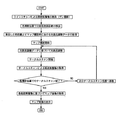
以下、広画角マップ撮影時の制御動作について説明する。図4は、広画角マップ撮影時の制御動作をフローチャートにて示した図である。
<Control action>
Hereinafter, the control operation at the time of wide-angle map shooting will be described. FIG. 4 is a flowchart showing the control operation during wide-angle map shooting.
検者によって撮影部位が選択されると、制御部70は、固視標投影ユニット300を制御し、選択された撮影部位に対応する位置に固視位置を移動させる。例えば、黄斑撮影モードが選択されると、固視位置が中央に設定され、乳頭部撮影モードが選択されると、固視位置が鼻側かつ若干上側に設定される。なお、固視位置は、左右眼で略左右対称な位置関係となる。すなわち、本実施形態においては、目的撮影部位と固視標投影ユニット300の位置とが関連付けされており、これに基づき固視位置が設定されるので、検者が所望する眼底部位の断層画像が容易に取得できる。本実施形態においては、広画角の黄斑撮影モードを例として説明する。なお、撮影画角の設定は撮影モード内で行える構成とする。もちろん、撮影画角は、撮影モードが設定されていない状態で設定できる構成としてもよいし、撮影モードに応じて予め撮影画角が設定されている構成としてもよい。
When the imaging part is selected by the examiner, the
検者によって、黄斑撮影モードが設定され、撮影画角が広画角(例えば、画角30°)に設定されると、黄斑を中心とした断層像の広画角マップ撮影が行われる。そして、検者によって、コントロール部74の図無きマップ撮影開始のスイッチが操作されると、制御部70は、マップ撮影を開始する。
When the examiner sets the macular photographing mode and the photographing angle of view is set to a wide angle of view (for example, an angle of view of 30 °), wide-angle map photographing of a tomographic image centered on the macular is performed. When the examiner operates a map shooting start switch (not shown) of the
マップ撮影時において、各サークルスキャンを行う場合、制御部70は、複数のサークルスキャンの走査領域に関して、基準位置Bに対する眼底の高さ情報を取得し、取得された高さ情報に基づいて光路差の調整を行う。制御部70は、高さ情報を得るため、走査部23を制御して、サークルスキャンにおける走査中心を通るようにラインスキャンを行う。そして、ラインスキャンにて取得された眼底断層像を処理して、各横断位置での深さ方向における眼底断層像の取得位置を取得することにより眼底の高さ情報を得る。
When performing each circle scan at the time of map shooting, the
初めに、ラインスキャンによるプレ撮影が行われる。制御部70は、走査部23を制御し、ラインスキャンによる光切断面がサークルスキャンにて用いられる走査中心Oを通るように、眼底に対してラインスキャンを行う。
First, pre-photographing by line scanning is performed. The
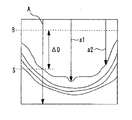
図5はラインスキャンによって取得された断層画像の一例を示す図である。制御部70は、取得した眼底断層像において、深さ方向(Aスキャン方向)に走査する複数の走査線を設定し、各走査線上における輝度分布データを求める。制御部70は、各走査線に対応する輝度分布からエッジ検出を行い、断層像(眼底)の表面位置を検出する。例えば、図5に示すように、走査線Aが設定され、その輝度分布データが取得される。そして、断層像の輝度レベルが検出され、眼底の表面位置Sが画像処理により抽出される。
FIG. 5 is a diagram showing an example of a tomographic image acquired by line scanning. The
次いで、制御部70は、横断方向における各Aスキャン方向の表面位置と基準位置Bとの距離を算出する。例えば、図5に示すように、走査線Aにおいて、眼底の表面位置Sが検出され、表面位置Sと基準位置Bとの距離ΔDが算出される。
Next, the
基準位置Bは、マップ撮影時において、中心に対する距離が互いに異なる複数のサークルスキャンを行う際に、各サークルスキャンによって取得される眼底断層像が、ほぼ同じ深さ位置にて取得され、同一の感度にて取得されるための目標位置である。 As for the reference position B, when performing a plurality of circle scans having different distances from the center at the time of map shooting, the fundus tomographic image acquired by each circle scan is acquired at substantially the same depth position, and the same sensitivity is obtained. This is the target position for acquisition at.
制御部70によって、各走査線(例えば、走査線a1や走査線a2)において、各表面位置から基準位置Bまでの距離が算出され、その各走査線の位置情報とともに、走査線毎に算出された距離がメモリ72に記憶される。なお、算出された距離は、マップ撮影時の光路長調整時に用いられる。
The
マップ撮影時において各サークルスキャンを行う場合、制御部70は、走査線それぞれで算出された距離に基づいて、基準位置Bと眼底の表面位置とが一致するように光路長調整を行う(詳しくは、後述する)。これにより、複数のサークルスキャンによって取得された各断層像は、互いに、眼底の表面位置がほぼ同一位置、同一感度にて取得される。すなわち、どの眼底撮影位置で撮影をおこなっても同一の感度で、眼底断層像が取得される。なお、基準位置Bは、感度の高い画像を取得できる測定光と参照光との光路長一致位置の近傍に設定されることが望ましい。
When each circle scan is performed at the time of map shooting, the
本実施形態における光路長一致位置の近傍とは、眼底断層像が高感度で取得される位置であり、例えば、光路長一致位置を基準に±Zmmの撮像範囲に設定された装置は、各サークルスキャンにて取得される複数の眼底断層像の表面が、光路長一致位置から±1/2Zmmまでの領域に位置するように測定光と参照光の光路差を調整する。これにより、相対的に高感度にて複数の眼底断層像が得られる。 In the present embodiment, the vicinity of the optical path length coincidence position is a position at which the fundus tomographic image is acquired with high sensitivity. For example, an apparatus set in an imaging range of ± Z mm with respect to the optical path length coincidence position is a circle. The optical path difference between the measurement light and the reference light is adjusted so that the surfaces of a plurality of fundus tomographic images acquired by scanning are located in a region from the optical path length matching position to ± 1/2 Zmm. Thereby, a plurality of fundus tomographic images are obtained with relatively high sensitivity.
なお、プレ撮影にて取得された眼底断層像において、各表面位置から基準位置Bまでの距離を算出するための各走査線が通過した走査位置と、マップ撮影を行う際の各サークルスキャンによる走査位置とは、同一の走査位置となるように対応づけ(設定)されている。そして、これらの走査位置設定情報は、メモリ72に記憶されている。また、マップ撮影時のサークルスキャンを行う撮影位置についても、予め設定され、メモリ72に記憶されている。
In the fundus tomographic image acquired by pre-imaging, the scanning position through which each scanning line for calculating the distance from each surface position to the reference position B has passed, and scanning by each circle scan when performing map imaging. The position is associated (set) so as to be the same scanning position. These pieces of scanning position setting information are stored in the
図6は、プレ撮影によって眼底上領域Gをラインスキャンした眼底断層像において各撮影位置とマップ撮影時におけるサークルスキャンの各走査位置の関係を示した図である。例えば、図6に示された眼底断層像の撮影位置P1上をAスキャン方向に走査した走査線A1とマップ撮影において眼底上の撮影位置P1を通るサークルスキャンC1は、対応づけがされている。また、撮影位置P2上では走査線A2とマップ撮影におけるサークルスキャンC2が対応づけされ、撮影位置P3上では走査線A3とマップ撮影におけるサークルスキャンC3が対応づけされて設定されている。このため、眼底表面位置から基準位置Bまでの距離を算出することによって、各撮影位置でサークルスキャンを行う際に、プレ撮影時の参照ミラー31の位置からどのくらい参照ミラー31を移動させれば、すべての撮影位置で同一の感度を取得できるか算出できる。すなわち、各撮影位置での距離に応じて、撮影位置毎にサークルスキャン時の参照ミラー31の移動量を設定することができる。
FIG. 6 is a diagram showing a relationship between each imaging position and each scanning position of the circle scan at the time of map imaging in the fundus tomographic image obtained by performing line scanning on the fundus oculi region G by pre-imaging. For example, the scanning line A1 scanned in the A-scan direction on the fundus tomographic image capturing position P1 shown in FIG. 6 is associated with the circle scan C1 passing through the image capturing position P1 on the fundus in the map image capturing. Further, the scanning line A2 and the circle scan C2 in the map photographing are associated with each other on the photographing position P2, and the scanning line A3 and the circle scan C3 in the map photographing are associated with each other on the photographing position P3. Therefore, by calculating the distance from the fundus surface position to the reference position B, when the circle scan is performed at each imaging position, how much the
より具体的には、各サークルスキャンによる撮影位置に応じて、眼底表面位置から基準位置Bまでの距離が算出されているため、参照ミラー31を移動させ光路長を調整することによって、眼底表面位置を基準位置Bに移動させるのに必要な移動量が算出される。
More specifically, since the distance from the fundus surface position to the reference position B is calculated according to the imaging position by each circle scan, the fundus surface position is adjusted by moving the
例えば、プレ撮影時の参照ミラー31の位置から、参照ミラー31の位置を撮影位置に応じた移動量分だけ逐次移動させることによって、光路長が調整され、その撮影位置における眼底表面位置が基準位置Bに移動される。
For example, the optical path length is adjusted by sequentially moving the position of the
制御部70は、メモリ72に記憶された各撮影位置における眼底表面位置から基準位置Bまでの距離と、参照ミラー31の移動量とのデータテーブルを参照して、その距離に基づいて、各撮影位置の参照ミラーの移動量を算出する。なお、距離と参照ミラーの移動量のデータテーブルは、予め、実験やシミュレーションによって算出される。
The
次いで、制御部70は、マップ撮影を行う。図7は、マップ撮影時のスキャン動作について説明する概略図である。図7では、走査中心が、黄斑中心に設定される。
Next, the
制御部70は、走査部23を制御してサークル径が互いに異なる複数のサークルスキャンを順次行うと共に、各サークルスキャンによって取得される複数の眼底断層像が光路長一致位置の近傍で取得されるように各サークルスキャンのサークル径に応じて測定光と参照光の光路差を調整する。
The
例えば、制御部70は、黄斑上に設定されたサークルスキャンC1を行い、眼底断層像を取得する。その後、順次、サークルスキャンの直径を変更して、撮影位置を変更し、撮影を行っていく。
For example, the
制御部70は、サークルスキャンC1の撮影位置に対応する参照ミラー31の移動量をメモリ72から呼び出す。そして、制御部70は、その移動量に基づいて、参照ミラー31を移動させて、光路長を調整する。制御部70は、光路長の調整が終了すると、サークルスキャンC1を開始し、眼底断層像を取得する。これにより、サークルスキャンC1において、眼底表面が基準位置Bに位置された状態の断層像データ(図8(a)参照)が得られる。
The
サークルスキャンC1での撮影が終了すると、制御部70は、サークルスキャンC2の撮影位置に対応する参照ミラー31の移動量に応じて光路長の調整を行い、光路長調整後、制御部70は、サークルスキャンC2を行い、眼底断層像(図8(b)参照)を取得する。
When shooting with the circle scan C1 ends, the
同様に、制御部70は、サークルスキャンC2での撮影完了後、次のサイズのサークルスキャンC3に合わせて光路長調整を行い、サークルスキャンによって眼底断層像(図8(c)参照)を取得する。制御部70は、所定のサイズ(例えば、直径9mm)のサークルスキャンによる眼底断層像を取得するまで、撮影位置に応じた光路長調整とサークルスキャンを繰り返し行う。
Similarly, after completion of imaging in the circle scan C2, the
各サークルスキャンの間隔は、眼底上の走査位置に関して互いに近接する。スキャン位置の近接性に関しては、スキャン位置が連続するパターンの他、断層観察における連続性が確保される程度にスキャン位置が互いに近接するパターン(例えば、150μm程度)が考えられる。 The intervals between the circle scans are close to each other with respect to the scan position on the fundus. Regarding the proximity of the scan positions, in addition to a pattern in which the scan positions are continuous, a pattern in which the scan positions are close to each other to the extent that continuity in tomographic observation is ensured (for example, about 150 μm) can be considered.
例えば、最初のサークルスキャンC1の直径は、黄斑の直径より小さいサイズに設定される(例えば、直径1.0mm)。また、本実施形態において、サークルスキャンのサイズは、直径1.0mmから0.1mmずつ大きくしていく構成とする。また、最大のサークルスキャンのサイズを直径9.0mmとする。このため、本実施形態において、直径1.0mmのサークルスキャンからスキャンが開始され、サークルスキャンのサイズを変更しながら、直径9.0mmのサークルスキャンまで、合計で81スキャン行い、三次元OCTデータが取得される。なお、本実施形態においては、サークルスキャンのサイズを1.0mmから0.1mmずつ大きくしていく構成としたが、サークルスキャンの間隔は、これに限定されない。また、各サークルスキャンのサイズや、複数のサークルスキャンによるスキャンエリアにおいても、これに限定されない。もちろん、検者が任意にサークルサイズやスキャンエリアの変更を設定できる構成を設けてもよい。 For example, the diameter of the first circle scan C1 is set to be smaller than the diameter of the macular (for example, 1.0 mm in diameter). In this embodiment, the size of the circle scan is increased from 1.0 mm to 0.1 mm in diameter. The maximum circle scan size is set to 9.0 mm in diameter. For this reason, in this embodiment, scanning is started from a circle scan with a diameter of 1.0 mm, and while changing the size of the circle scan, a total of 81 scans are performed up to a circle scan with a diameter of 9.0 mm. To be acquired. In this embodiment, the circle scan size is increased from 1.0 mm by 0.1 mm, but the circle scan interval is not limited to this. Further, the size of each circle scan and a scan area by a plurality of circle scans are not limited to this. Of course, a configuration in which the examiner can arbitrarily set the change of the circle size and the scan area may be provided.
以上のようにして、各サークルスキャンの撮影位置毎に光路長調整を行い、同一の感度にて、眼底断層像が取得されるようにする。各サークルスキャンによる眼底断層像が取得されると、制御部70は、それらの複数の眼底断層像を画像処理(複合処理)により、眼底の三次元OCTデータを取得する。そして、制御部70は、三次元OCTデータに基づいて、眼底各層の厚み(眼底の層厚分布)を測定する。その後、その測定結果に基づいて層厚マップ又は正常眼データを用いた差分マップを作成し、モニタ75に表示する。なお、三次元OCTデータを用いてして、三次元グラフィック画像を作成して、モニタ75に表示してもよい。
As described above, the optical path length is adjusted for each imaging position of each circle scan, and the fundus tomographic image is acquired with the same sensitivity. When the fundus tomographic image by each circle scan is acquired, the
三次元OCTデータの取得は、各サークルスキャンによってサークル状に取得された眼底断層像を同心円上に配列することによって行われる。なお、各サークルスキャンの眼底断層像は、中心部での眼底断層像と周辺部での眼底断層像で走査距離の違いから大きさが異なる。このため、これらの眼底断層像を同様の大きさで表示する場合、中心部の画像を引き伸ばして拡大表示することになる。しかしながら、眼底断層像間の解像度が中心部と周辺部で異なってしまう。また、周辺部の眼底断層像を縮小し、中心部の眼底断層像の大きさに調整すると、眼底断層像が小さくなり、観察しづらくなる。 The acquisition of the three-dimensional OCT data is performed by arranging the fundus tomographic images acquired in a circle shape by each circle scan on concentric circles. It should be noted that the fundus tomographic image of each circle scan is different in size between the fundus tomographic image at the center and the fundus tomographic image at the periphery due to the difference in scanning distance. Therefore, when these fundus tomographic images are displayed in the same size, the central image is enlarged and displayed. However, the resolution between fundus tomographic images differs between the central portion and the peripheral portion. Further, if the fundus tomographic image in the peripheral part is reduced and adjusted to the size of the fundus tomographic image in the central part, the fundus tomographic image becomes small and difficult to observe.
このため、眼底断層像を同一の解像度にて、好適に表示するために、中心部と周辺部で走査速度を変化させ、眼底断層像を取得する手法が挙げられる。この場合、例えば、中心部での走査速度を周辺部での走査速度よりも遅くし、取得される眼底断層像が引き伸ばされても、周辺部の眼底断層像の解像度と同様となるようにする。 For this reason, in order to display the fundus tomographic image suitably at the same resolution, there is a method of acquiring the fundus tomographic image by changing the scanning speed between the central part and the peripheral part. In this case, for example, the scanning speed at the central portion is made slower than the scanning speed at the peripheral portion so that the resolution of the fundus tomographic image in the peripheral portion is the same even if the acquired fundus tomographic image is enlarged. .
以上のように、サークルスキャンを用いて、同一の感度にて眼底断層像を取得していくことによって、全撮影領域において、感度の良いマップ撮影を行うことができる。 As described above, by acquiring a fundus tomographic image with the same sensitivity using the circle scan, map imaging with high sensitivity can be performed in the entire imaging region.
なお、本実施形態においては、眼底の表面位置を検出し、表面位置を断層画像中の基準位置Bに移動させるように光路長調整を行ったがこれに限定されない。本実施形態では、制御部70は、眼底内の所定の網膜層を検出し、その網膜層を基準位置Bに移動させ、光路長調整を行う。例えば、RPE(網膜色素上皮細胞)層を眼底断層像から抽出し、RPE層が基準位置に移動されるように光路長調整を行ってもよい。
In the present embodiment, the surface position of the fundus is detected and the optical path length adjustment is performed so as to move the surface position to the reference position B in the tomographic image, but the present invention is not limited to this. In the present embodiment, the
なお、本実施形態においては、プレ撮影によって各サークルスキャンに応じた参照ミラーの移動量を算出し、光路長調整を行う構成としたがこれに限定されない。例えば、サークルスキャン毎に、断層像データ取得前に基準位置Bへのトラッキングを行い、光路長調整を行っていく構成としてもよい。 In the present embodiment, the amount of movement of the reference mirror corresponding to each circle scan is calculated by pre-photographing and the optical path length is adjusted. However, the present invention is not limited to this. For example, for each circle scan, the tracking to the reference position B may be performed and the optical path length adjustment may be performed before tomographic image data acquisition.
なお、本実施形態においては、光路長一致位置に対して同じ深さ位置されるように、各サークルスキャンのサークル径に応じて測定光と参照光の光路差を調整したがこれに限定されない。各サークルスキャンにて取得される眼底断層像が高感度領域で位置されるように、光路差を調整する。例えば、各眼底断層像は、高感度領域において、位置ずれが許容される。 In the present embodiment, the optical path difference between the measurement light and the reference light is adjusted in accordance with the circle diameter of each circle scan so as to be positioned at the same depth with respect to the optical path length matching position, but the present invention is not limited to this. The optical path difference is adjusted so that the fundus tomographic image acquired by each circle scan is positioned in the high sensitivity region. For example, each fundus tomographic image is allowed to be displaced in the high sensitivity region.
なお、本実施形態においては、マップ撮影時にサークルスキャンを複数回行うことによって三次元OCTデータを取得する構成としたがこれに限定されない。例えば、サークルスキャンとその他のスキャンパターンを組み合わせてマップ撮影をおこなってもよい。例えば、黄斑周辺部(中心画角)においては、ラスタースキャンによって眼底上で測定光を二次元的走査することによって眼底の3次元断層像を取得し、湾曲度の大きい周辺画角においては、複数のサークルスキャンにて眼底上で測定光を二次元的走査することによって眼底断層像を取得する構成としてもよい。 In the present embodiment, three-dimensional OCT data is acquired by performing a circle scan a plurality of times during map shooting, but the present invention is not limited to this. For example, map shooting may be performed by combining a circle scan and other scan patterns. For example, in the macular peripheral part (center angle of view), a three-dimensional tomographic image of the fundus is obtained by two-dimensional scanning of the measurement light on the fundus by raster scanning, and in the peripheral field angle with a large degree of curvature, a plurality of Alternatively, the tomographic image of the fundus may be obtained by two-dimensionally scanning the measurement light on the fundus with the circle scan.
また、本発明は、撮影条件の異なる複数のスキャンを順次行う構成であれば適用可能である。例えば、スキャン長、スキャン位置等に応じて変更する。例えば、複数のスキャン長(3mm、6mm、9mm等)にてスキャンを行う場合、複数のスキャン長の内、相対的に長いスキャン長(例えば、最も長いスキャン長)にて、プレ撮影として、スキャンを行う。そして、プレ撮影によって、取得された断層像より、他のスキャン長に対応する走査範囲での眼底の位置(例えば、眼底表面の位置、ある網膜層(例えば、網膜色素上皮層)の位置)を検出する。そして、他のスキャン長での撮影において、プレ撮影にて検出された眼底の位置が、基準位置に位置するように、光路長調整を行い、同一の感度にて、眼底断層像が取得されるようにする。 The present invention is applicable to any configuration that sequentially performs a plurality of scans with different imaging conditions. For example, it is changed according to the scan length, scan position, and the like. For example, when scanning with a plurality of scan lengths (3 mm, 6 mm, 9 mm, etc.), scanning is performed as pre-photographing with a relatively long scan length (for example, the longest scan length) among the plurality of scan lengths. I do. Then, the fundus position (for example, the position of the fundus surface, the position of a certain retinal layer (for example, the retinal pigment epithelium layer)) in the scanning range corresponding to another scan length is obtained from the tomogram acquired by pre-imaging. To detect. In imaging with other scan lengths, the optical path length is adjusted so that the fundus position detected in the pre-imaging is positioned at the reference position, and a fundus tomographic image is acquired with the same sensitivity. Like that.
また、例えば、複数の異なるスキャンパターンにてスキャンを行う場合、第1のスキャンパターンでの撮影をプレ撮影として用い、第2のスキャンパターンにおける眼底上の走査範囲の少なくとも一部を含むようなスキャンにて、断層像を取得する。プレ撮影によって得られた断層像により、第2のスキャンパターンによる眼底上の走査範囲での眼底位置を検出することができる。そして、第2のスキャンパターンでの撮影を行う場合、検出された眼底位置が基準位置に位置するように、スキャン位置毎に光路長調整を行い、第2のスキャンパターンの走査位置と第1のスキャンパターンの走査位置との間で同一の感度にて、眼底断層像が取得されるようにする。ここで、第2のスキャンパターンの中で異なる複数の断層像を得る場合(例えば、クロススキャン)、各断層像が同一の感度にて取得されるように光路長が制御される。 In addition, for example, when scanning with a plurality of different scan patterns, the scan using the first scan pattern is used as a pre-scan, and the scan includes at least a part of the scan range on the fundus in the second scan pattern. To obtain a tomographic image. The tomographic image obtained by the pre-imaging can detect the fundus position in the scanning range on the fundus according to the second scan pattern. When photographing with the second scan pattern, the optical path length is adjusted for each scan position so that the detected fundus position is located at the reference position, and the scan position of the second scan pattern is compared with the first scan pattern. A fundus tomographic image is acquired with the same sensitivity to the scanning position of the scan pattern. Here, when a plurality of different tomographic images are obtained in the second scan pattern (for example, cross scan), the optical path length is controlled so that each tomographic image is acquired with the same sensitivity.
具体例として、異なるスキャンパターンとしては、クロススキャンやラジアルスキャン等の組み合わせが考えられる。例えば、クロススキャン(X方向及びY方向のスキャン)の場合には、プレ撮影として、サークルスキャンにて、断層像を撮影するようにすれば、X方向及びY方向の両方のスキャンでの眼底位置を検出することができる。そして、クロススキャンを行う場合、検出された眼底位置が基準位置に位置するように、スキャン位置毎に光路長調整を行い、X方向及びY方向の両方のスキャン位置にて、同一の感度にて、眼底断層像が取得されるようにする。なお、一度のプレ撮影で全てのスキャン位置を含む断層像が取得できない場合には、複数のプレ撮影を行うようにしてもよい。 As a specific example, a combination of cross scan, radial scan, or the like can be considered as different scan patterns. For example, in the case of a cross scan (scan in the X direction and the Y direction), if a tomographic image is taken by a circle scan as pre-photographing, the fundus position in both the X direction and Y direction scans Can be detected. When performing a cross scan, the optical path length is adjusted for each scan position so that the detected fundus position is located at the reference position, and the same sensitivity is obtained at both the X and Y scan positions. The fundus tomographic image is acquired. If a tomographic image including all scan positions cannot be acquired by one pre-photographing, a plurality of pre-photographs may be performed.
また、上記複数の異なるスキャンパターンにて限定されずものではなく、異なる複数のスキャン位置でのスキャンであれば、本実施形態の技術の適用は可能である。 Further, the present invention is not limited to the plurality of different scan patterns, and the technique of the present embodiment can be applied as long as the scan is performed at a plurality of different scan positions.
例えば、スキャンパターンとスキャン長が同一で、眼底上の撮影の位置が異なるスキャンが挙げられる。例えば、ラインスキャンやサークルスキャンにて、乳頭近傍位置と黄斑近傍位置をスキャンすることが挙げられる。 For example, scans having the same scan pattern and scan length and different photographing positions on the fundus can be mentioned. For example, the position near the nipple and the position near the macula can be scanned by line scanning or circle scanning.
このような場合、上記のように、眼底上の第1の撮影部位(例えば、乳頭近傍位置)での撮影をプレ撮影として用い、眼底上の第2の撮影部位(例えば、黄斑近傍位置)の少なくとも一部を含むようなスキャンにて、断層像を取得する。もちろん、複数のプレ撮影を行うようにしてもよい。そして、プレ撮影として取得された断層像より眼底位置を検出する。そして、眼底上の第2の撮影部位にて撮影を行う場合、第1の撮影部位にて検出された眼底位置が基準位置に位置するように、光路長調整を行い、第2の撮影部位の走査位置にて、同一の感度にて、眼底断層像が取得されるようにする。なお、第2の撮影部位での撮影において、異なる複数の断層像を得る場合(例えば、クロススキャン)、各断層像が同一の感度にて取得されるように光路長が制御される。 In such a case, as described above, imaging at the first imaging region on the fundus (for example, the position near the nipple) is used as pre-imaging, and the second imaging region on the fundus (for example, the position near the macula) is used. A tomographic image is acquired by a scan including at least a part. Of course, you may make it perform several pre imaging | photography. Then, the fundus position is detected from the tomographic image acquired as the pre-photographing. Then, when imaging is performed at the second imaging region on the fundus, the optical path length is adjusted so that the fundus position detected at the first imaging region is positioned at the reference position, and the second imaging region is detected. A fundus tomographic image is acquired at the scanning position with the same sensitivity. Note that, in imaging at the second imaging region, when obtaining a plurality of different tomographic images (for example, cross scan), the optical path length is controlled so that each tomographic image is acquired with the same sensitivity.
なお、本実施形態においては、参照ミラー31を移動させることによって撮影位置に応じた光路長調整を行う構成としたがこれに限定されない。本実施形態の装置は、測定光又は参照光の光路中に配置された光学部材を、測定光と参照光の光路差を調整するために移動させる駆動部を備える。例えば、測定光の光路長と参照光の光路長との光路長差を変更するための構成としては、測定光の光路長を変化させて参照光との光路長を調整するような構成としてもよい。例えば、図1の光学系において、参照ミラー31を固定とし、コリメータレンズ21とファイバー端部39bとを一体的に移動させることにより参照光の光路長に対して測定光の光路長を変化させるような構成が考えられる。
In the present embodiment, the optical path length is adjusted according to the shooting position by moving the
なお、上記説明において、スペクトルメータを用いたスペクトルドメインOCTを例にとって説明したが、これに限定されない。例えば、波長可変光源を備えるSS−OCT(Swept source OCT)であってもよい。 In the above description, the spectrum domain OCT using a spectrum meter has been described as an example, but the present invention is not limited to this. For example, SS-OCT (Swept source OCT) provided with a wavelength variable light source may be used.
23 走査部
24 フォーカシングレンズ
24a 駆動機構
31 参照ミラー
33 ポラライザ
34 駆動機構
50 駆動機構
70 制御部
72 メモリ
75 表示モニタ
200 OCT光学系
300 固視標投影ユニット
DESCRIPTION OF
Claims (3)
前記測定光の光路中に配置され,眼底上で前記測定光を走査する光スキャナと、
前記受光素子から出力されるスペクトル信号をフーリエ解析して眼底断層像を得る眼底断層像撮影装置において、
前記光スキャナを制御して、サークル径が互いに異なる複数のサークルスキャンを順次行うと共に、各サークルスキャンによって取得される眼底断層像が同一の感度で取得されるように測定光と参照光の光路長差を各サークルスキャン単位で調整する制御手段と、
を備える、ことを特徴とする眼底断層像撮影装置。 The light emitted from the light source is divided into measurement light and reference light, the measurement light is guided to the fundus of the eye to be examined, the reference light is guided to the reference optical system, and then the measurement light reflected from the fundus and the reference light are combined. An interference optical system for causing the light receiving element to receive the light spectrum;
An optical scanner arranged in the optical path of the measurement light and scanning the measurement light on the fundus;
In the fundus tomography apparatus for obtaining a fundus tomogram by performing Fourier analysis on the spectrum signal output from the light receiving element,
The optical scanner is controlled to sequentially perform a plurality of circle scans having different circle diameters , and the optical path lengths of the measurement light and the reference light so that the fundus tomographic image acquired by each circle scan is acquired with the same sensitivity. Control means for adjusting the difference for each circle scan ;
A fundus tomography apparatus characterized by comprising:
Priority Applications (1)
| Application Number | Priority Date | Filing Date | Title |
|---|---|---|---|
| JP2012202492A JP6098079B2 (en) | 2011-09-29 | 2012-09-14 | Fundus tomography system |
Applications Claiming Priority (3)
| Application Number | Priority Date | Filing Date | Title |
|---|---|---|---|
| JP2011214236 | 2011-09-29 | ||
| JP2011214236 | 2011-09-29 | ||
| JP2012202492A JP6098079B2 (en) | 2011-09-29 | 2012-09-14 | Fundus tomography system |
Publications (3)
| Publication Number | Publication Date |
|---|---|
| JP2013081763A JP2013081763A (en) | 2013-05-09 |
| JP2013081763A5 JP2013081763A5 (en) | 2015-11-05 |
| JP6098079B2 true JP6098079B2 (en) | 2017-03-22 |
Family
ID=48527585
Family Applications (1)
| Application Number | Title | Priority Date | Filing Date |
|---|---|---|---|
| JP2012202492A Active JP6098079B2 (en) | 2011-09-29 | 2012-09-14 | Fundus tomography system |
Country Status (1)
| Country | Link |
|---|---|
| JP (1) | JP6098079B2 (en) |
Families Citing this family (6)
| Publication number | Priority date | Publication date | Assignee | Title |
|---|---|---|---|---|
| JP2014226173A (en) * | 2013-05-20 | 2014-12-08 | 株式会社トーメーコーポレーション | Optical tomographic image generating device, method for controlling the optical tomographic image generating device, program therefor, and storage medium |
| JP6756516B2 (en) * | 2016-04-28 | 2020-09-16 | 株式会社トプコン | Ophthalmologic imaging equipment |
| JP6940960B2 (en) * | 2017-02-28 | 2021-09-29 | キヤノン株式会社 | Imaging device, operation method and program of imaging device |
| EP3845119A4 (en) | 2018-08-29 | 2022-05-04 | Topcon Corporation | Ophthalmology device, and control method therefor |
| JP7325675B2 (en) | 2018-09-27 | 2023-08-14 | 株式会社トプコン | ophthalmic imaging equipment |
| JP2021194243A (en) * | 2020-06-15 | 2021-12-27 | 株式会社トプコン | Ophthalmologic apparatus, control method of ophthalmologic apparatus, and program |
Family Cites Families (7)
| Publication number | Priority date | Publication date | Assignee | Title |
|---|---|---|---|---|
| WO2004098396A2 (en) * | 2003-05-01 | 2004-11-18 | The Cleveland Clinic Foundation | Method and apparatus for measuring a retinal sublayer characteristic |
| WO2006022045A1 (en) * | 2004-08-26 | 2006-03-02 | National University Corporation Nagoya University | Optical interference tomograph |
| JP5523658B2 (en) * | 2007-03-23 | 2014-06-18 | 株式会社トプコン | Optical image measuring device |
| JP5679630B2 (en) * | 2008-12-26 | 2015-03-04 | キヤノン株式会社 | Optical tomographic imaging apparatus and method |
| JP5483873B2 (en) * | 2008-12-26 | 2014-05-07 | キヤノン株式会社 | Optical tomographic imaging apparatus and optical tomographic imaging method |
| JP5489539B2 (en) * | 2009-06-05 | 2014-05-14 | キヤノン株式会社 | Imaging apparatus, imaging apparatus control method, and tomographic image forming method by OCT |
| JP5432625B2 (en) * | 2009-07-29 | 2014-03-05 | 株式会社トプコン | Ophthalmic observation device |
-
2012
- 2012-09-14 JP JP2012202492A patent/JP6098079B2/en active Active
Also Published As
| Publication number | Publication date |
|---|---|
| JP2013081763A (en) | 2013-05-09 |
Similar Documents
| Publication | Publication Date | Title |
|---|---|---|
| US9743830B2 (en) | Fundus photography device | |
| US7980696B1 (en) | Ophthalmic photographing apparatus | |
| JP6007527B2 (en) | Fundus photographing device | |
| JP5255524B2 (en) | Optical tomographic imaging device, optical tomographic image processing device. | |
| US20130107277A1 (en) | Optical tomographic imaging apparatus and imaging method therefor | |
| JP5701660B2 (en) | Fundus photographing device | |
| JP6098079B2 (en) | Fundus tomography system | |
| EP2644085B1 (en) | Fundus photographing apparatus | |
| JP6221516B2 (en) | Ophthalmic photographing apparatus and ophthalmic photographing program | |
| US9675243B2 (en) | Ophthalmic photographing apparatus | |
| JP2018175258A (en) | Image generating device, image generation method, and program | |
| US10653309B2 (en) | Ophthalmologic apparatus, and ophthalmologic imaging method | |
| US20150272432A1 (en) | Ophthalmic photography device, ophthalmic photography method, and ophthalmic photography program | |
| JP2016158906A (en) | Eye axial length measurement device, eye ball shape information acquisition method, and eye ball shape information acquisition program | |
| JP6040562B2 (en) | Attachment for fundus photography device | |
| JP2018201858A (en) | Spectacle-wearing parameter acquisition apparatus, spectacle-wearing parameter acquisition method, and spectacle-wearing parameter acquisition program | |
| JP5807371B2 (en) | Ophthalmic imaging equipment | |
| JP2005348755A (en) | Ophthalmologic measuring device | |
| JP2018102789A (en) | Optical coherence tomography apparatus | |
| JP2018023675A (en) | Optical tomographic imaging apparatus | |
| JP6160807B2 (en) | Ophthalmic photographing apparatus and ophthalmic photographing program | |
| JP6775995B2 (en) | Optical tomography imaging device, operation method of optical tomography imaging device, and program | |
| JP2015085043A (en) | Fundus photographing device | |
| WO2022113790A1 (en) | Optical coherence tomography device and control program therefor | |
| JP5680133B2 (en) | Ophthalmic equipment |
Legal Events
| Date | Code | Title | Description |
|---|---|---|---|
| A521 | Request for written amendment filed |
Free format text: JAPANESE INTERMEDIATE CODE: A523 Effective date: 20150911 |
|
| A621 | Written request for application examination |
Free format text: JAPANESE INTERMEDIATE CODE: A621 Effective date: 20150911 |
|
| A977 | Report on retrieval |
Free format text: JAPANESE INTERMEDIATE CODE: A971007 Effective date: 20160624 |
|
| A131 | Notification of reasons for refusal |
Free format text: JAPANESE INTERMEDIATE CODE: A131 Effective date: 20160628 |
|
| A521 | Request for written amendment filed |
Free format text: JAPANESE INTERMEDIATE CODE: A523 Effective date: 20160826 |
|
| TRDD | Decision of grant or rejection written | ||
| A01 | Written decision to grant a patent or to grant a registration (utility model) |
Free format text: JAPANESE INTERMEDIATE CODE: A01 Effective date: 20170124 |
|
| A61 | First payment of annual fees (during grant procedure) |
Free format text: JAPANESE INTERMEDIATE CODE: A61 Effective date: 20170206 |
|
| R150 | Certificate of patent or registration of utility model |
Ref document number: 6098079 Country of ref document: JP Free format text: JAPANESE INTERMEDIATE CODE: R150 |
|
| R250 | Receipt of annual fees |
Free format text: JAPANESE INTERMEDIATE CODE: R250 |
|
| R250 | Receipt of annual fees |
Free format text: JAPANESE INTERMEDIATE CODE: R250 |
|
| R250 | Receipt of annual fees |
Free format text: JAPANESE INTERMEDIATE CODE: R250 |
|
| R250 | Receipt of annual fees |
Free format text: JAPANESE INTERMEDIATE CODE: R250 |
|
| R250 | Receipt of annual fees |
Free format text: JAPANESE INTERMEDIATE CODE: R250 |