JP6071693B2 - Route search device and route search system - Google Patents
Route search device and route search system Download PDFInfo
- Publication number
- JP6071693B2 JP6071693B2 JP2013066236A JP2013066236A JP6071693B2 JP 6071693 B2 JP6071693 B2 JP 6071693B2 JP 2013066236 A JP2013066236 A JP 2013066236A JP 2013066236 A JP2013066236 A JP 2013066236A JP 6071693 B2 JP6071693 B2 JP 6071693B2
- Authority
- JP
- Japan
- Prior art keywords
- route
- label
- node
- link
- point
- Prior art date
- Legal status (The legal status is an assumption and is not a legal conclusion. Google has not performed a legal analysis and makes no representation as to the accuracy of the status listed.)
- Expired - Fee Related
Links
Images


Landscapes
- Instructional Devices (AREA)
- Navigation (AREA)
- Traffic Control Systems (AREA)
Description
本発明は、経路探索装置に関する。 The present invention relates to a route search apparatus.
近年では、出発地点から到着地点までの経路を探索する経路探索装置として、自動車に搭載されたカーナビゲーションシステム、携帯電話機、携帯ゲーム機、PND(Personal Navigation Device)およびPDA(Personal Digital Assistant)が知られている。経路探索装置の中には、出発地点から到着地点までの経路として、利用者に複数の経路を提示するものもある。 In recent years, car navigation systems, mobile phones, portable game machines, PNDs (Personal Navigation Devices) and PDAs (Personal Digital Assistants) installed in automobiles are known as route search devices for searching for routes from departure points to arrival points. It has been. Some route search devices present a plurality of routes to the user as routes from the departure point to the arrival point.
例えば、特許文献1には、出発地点から出発地点と異なる到着地点に至る経路の探索結果が記憶され、その後、前回の探索結果の経路と同一の出発地点から同一の到着地点に至る経路が探索されると、前回の探索結果の経路に含まれるリンクのリンクコストを大きくして、前回の探索結果の経路と異なる経路を探索する経路探索装置について開示されている。
For example,
しかし、特許文献1に記載された技術では、探索範囲808と探索範囲809との間の領域は、ネットワークが疎な状態である階層3のみで探索を行っているため、複数の経路を探索しようとしても経路の選択肢が限られるという課題があった。また、出発地点から到着地点に至る複数の経路を探索したい場合に、出発地点から到着地点に至る1つの経路を探索した後、また新たに、出発地点から到着地点に至る経路を探索する処理が必要だった。さらにまた、出発地点から到着地点に至る複数の経路が探索された場合に、1つの経路に含まれるノードやリンクが、他の経路におけるノードやリンクと重複しない場合があり、探索される経路に関係性がなく、1つの経路と関連性を持った経路を探索したいとの課題があった。
However, in the technique described in
本発明は、上述の課題の少なくとも一部を解決するためになされたものであり、以下の形態として実現することが可能である。 SUMMARY An advantage of some aspects of the invention is to solve at least a part of the problems described above, and the invention can be implemented as the following forms.
(1)本発明の一形態によれば、リンクとノードとを含むネットワーク上における任意の異なる2つの地点を結ぶ経路を探索する経路探索装置が提供される。この経路探索装置は、第1地点と第2地点とを特定するデータを取得する地点取得部と:各リンクの通過に要する時間を表わすリンクコストを特定するデータを記憶する経路情報記憶部と:前記ネットワーク上の所定の部分領域について、第1の詳細度の複数のリンクから構成される第1のリンク群を探索することにより、前記第1地点から前記第2地点に至る経路である第1の経路を設定する第1経路設定部と:前記第1の経路のリンクコストの累計値に加える許容時間を特定するデータを取得する許容時間取得部と:前記所定の部分領域について、前記第1の詳細度よりも詳細な第2の詳細度の複数のリンクから構成される第2のリンク群を探索することにより、前記第1地点から前記第2地点に至る、少なくとも前記第1の経路と一部が異なる経路を第2の経路として設定する第2経路設定部と、を備え、前記第2経路設定部は、前記リンクコストの累計値が前記第1の経路のリンクコストの累計値に前記許容時間を加えた値以下である経路を第2の経路として設定する。
また、本発明の一形態によれば、リンクとノードとを含むネットワーク上における任意の異なる2つの地点を結ぶ経路を探索する経路探索装置が提供される。この経路探索装置は、第1地点と第2地点とを特定するデータを取得する地点取得部と;前記ネットワーク上の所定の部分領域について、第1の詳細度の複数のリンクから構成される第1のリンク群を探索することにより、前記第1地点から前記第2地点に至る経路である第1の経路を設定する第1経路設定部と;前記所定の部分領域について、前記第1の詳細度よりも詳細な第2の詳細度の複数のリンクから構成される第2のリンク群に対して、探索する前記第2のリンク群に含まれるリンクを制限して探索することにより、前記第1地点から前記第2地点に至る、少なくとも前記第1の経路と一部が異なる経路を第2の経路として設定する第2経路設定部と、を備える。この形態の経路探索装置によれば、探索する前記第2のリンク群に含まれるリンクを制限して探索することによって、第2の経路の選択肢をあまり限定されないとともに、第2の経路の探索時間の増大を抑制することができる。
(1) According to one aspect of the present invention, there is provided a route search device that searches for a route connecting any two different points on a network including a link and a node. This route search device includes a point acquisition unit that acquires data for specifying a first point and a second point; a route information storage unit that stores data for specifying a link cost representing a time required for each link to pass through: A first route that is a route from the first point to the second point by searching for a first link group composed of a plurality of links having a first level of detail for a predetermined partial area on the network. A first route setting unit that sets a route of the first route: an allowable time acquisition unit that acquires data for specifying an allowable time to be added to the cumulative value of the link cost of the first route; By searching for a second link group composed of a plurality of links having a second detail level that is more detailed than the detail level, at least the first route from the first point to the second point part A second route setting unit configured to set a different route as a second route, wherein the second route setting unit sets the allowable time to the cumulative value of the link cost to the cumulative value of the link cost of the first route. A route that is equal to or less than the value obtained by adding is set as the second route.
Moreover, according to one form of this invention, the route search apparatus which searches the path | route which connects the arbitrary two different points on the network containing a link and a node is provided. The route search device includes: a point acquisition unit that acquires data for specifying a first point and a second point; and a predetermined partial area on the network including a plurality of links having a first degree of detail. A first route setting unit that sets a first route that is a route from the first point to the second point by searching for one link group; and the first details for the predetermined partial region The second link group composed of a plurality of links having a second level of detail that is more detailed than the second level, by limiting and searching for links included in the second link group to be searched, A second route setting unit configured to set, as a second route, a route that is at least partially different from the first route from the first point to the second point. According to the route search device of this aspect, the search of the second route is not limited so much by limiting the links included in the second link group to be searched, and the search time of the second route is not so limited. Can be suppressed.
(2)上記形態の経路探索装置において、前記第2経路設定部は、前記所定の部分領域について探索する前記第2の詳細度の複数のリンクを制限するために、前記第1の経路に含まれるノードを起点として前記所定の部分領域を探索して、前記第2の経路を設定してもよい。この形態の経路探索装置によれば、第1の経路に含まれるノードを起点として第2の経路が探索されるので、第2の経路をより効率良く設定できる。 (2) In the route search device of the above aspect, the second route setting unit is included in the first route in order to limit a plurality of links having the second level of detail to be searched for the predetermined partial area. The second route may be set by searching the predetermined partial area starting from a node to be started. According to the route search device of this aspect, since the second route is searched starting from the node included in the first route, the second route can be set more efficiently.
(3)上記形態の経路探索装置において、前記第2経路設定部は、前記第1経路設定部により設定された前記第1の経路が所定数以下の場合に前記第2の経路を設定してもよい。この形態の経路探索装置によれば、十分な数の第1の経路が探索されて設定されている場合には、第2の経路が設定されないため、経路探索の処理を抑制でき、かつ、迅速に第1地点から第2地点に至る経路を探索できる。 (3) In the route search device according to the above aspect, the second route setting unit sets the second route when the first route set by the first route setting unit is a predetermined number or less. Also good. According to the route search device of this aspect, when a sufficient number of first routes are searched and set, the second route is not set, so that the route search process can be suppressed and quickly performed. The route from the first point to the second point can be searched.
(4)上記形態の経路探索装置において、前記第1経路設定部は、各リンクに対して進行方向に基づき設定された規制を考慮して、前記第1地点から任意のノードに至る順探索経路を探索し、前記第2地点から任意のノードに至る逆探索経路を探索し、前記順探索経路と前記逆探索経路とに含まれるノードである重複ノードが出現した場合に、前記重複ノードを含む前記順探索経路と前記逆探索経路とに基づいて前記第1の経路を設定してもよい。この形態の経路探索装置によれば、順探索経路の探索と逆探索経路の探索とによって第1地点から第2地点に至る経路を探索するため、効率良く、かつ、迅速に第1地点から第2地点に至る経路を探索できる。 (4) In the route search device according to the above aspect, the first route setting unit considers a restriction set based on a traveling direction for each link, and a forward search route from the first point to an arbitrary node. And search for a reverse search route from the second point to an arbitrary node, and if a duplicate node that is a node included in the forward search route and the reverse search route appears, the duplicate node is included. The first route may be set based on the forward search route and the reverse search route. According to the route search device of this aspect, since the route from the first point to the second point is searched by the search for the forward search route and the search for the reverse search route, the route search from the first point can be performed efficiently and quickly. A route to two points can be searched.
(5)上記形態の経路探索装置において、前記第1経路設定部は、前記所定の部分領域よりも前記第1地点に近い領域について、前記第1のリンク群よりも詳細な複数のリンクから構成される他のリンク群を探索した後に、前記所定の部分領域を探索してもよい。この形態の経路探索装置によれば、階層的探索の利点を生かしつつ、第2の経路の選択肢をあまり限定されないようにすることができる。 (5) In the route search device according to the above aspect, the first route setting unit includes a plurality of links that are more detailed than the first link group in a region closer to the first point than the predetermined partial region. The predetermined partial area may be searched after searching for another link group. According to the route search device of this aspect, the options of the second route can be made not so limited while taking advantage of the hierarchical search.
(6)上記形態の経路探索装置において、さらに;各リンクの通過に要する時間を表わすリンクコストを特定するデータを記憶する経路情報記憶部と;複数の特定のノードのそれぞれに対してラベル情報を付与するラベル情報付与部であって、前記ラベル情報は、前記第1地点から前記特定のノードに至る特定の経路におけるリンクコストの累計値と、前記特定の経路に含まれるリンクを介して前記特定のノードに隣接するノードである直前ノードに付与された前記ラベル情報である直前ラベル情報と、を含む、ラベル情報付与部と;前記第1の経路のリンクコストの累計値に加える許容時間を特定するデータを取得する許容時間取得部と、を備え;前記第1経路設定部は、前記第1地点から前記第2地点に至る経路の内、前記ラベル情報に基づいて特定される経路のリンクコストの累計値が最も小さくなる経路を最適経路として設定し;前記第2経路設定部は、前記第1の経路に含まれるノードに付与された前記ラベル情報と、前記最適経路と、に基づいて、リンクコストの累計値が前記第1の経路のリンクコストの累計値に前記許容時間を加えた値以下である経路を第2の経路として設定してもよい。この形態の経路探索装置によれば、リンクコストの累計値が最も小さい経路と、探索時に付与されたラベルと、に基づいて前記第2の経路が設定されるため、1つの経路が設定された後に、再度、第1地点から第2地点に至るノードへのラベルの付与が不要であり、リンクコストの累計値が小さい経路を効率良く設定できる。 (6) In the route search device of the above aspect, a route information storage unit that stores data for specifying a link cost representing a time required for each link to pass; label information for each of a plurality of specific nodes; A label information adding unit for providing the label information, the cumulative value of a link cost in a specific route from the first point to the specific node, and the specific via a link included in the specific route; A label information adding unit including the immediately preceding label information which is the label information given to the immediately preceding node which is a node adjacent to the node; and specifying an allowable time to be added to the cumulative value of the link cost of the first route An allowable time acquisition unit for acquiring data to be performed; the first route setting unit includes the label information in a route from the first point to the second point. A path having the smallest cumulative value of link costs of the path identified as the optimal path is set as the optimal path; the second path setting unit includes the label information given to the node included in the first path; Based on the optimum route, a route whose cumulative link cost is less than or equal to the sum of the link cost of the first route plus the allowable time may be set as the second route. According to the route searching apparatus of this embodiment, since the cumulative value of the link cost and smallest path, the label assigned to the time of the search, the second path is set based on one route is set Later, it is not necessary to assign a label to the node from the first point to the second point again, and a route with a small cumulative link cost can be set efficiently.
なお、本発明は、種々の態様で実現することが可能であり、例えば、経路探索装置および方法、経路探索システムおよび方法、情報端末装置、情報送信装置および方法、携帯端末装置、情報処理サーバ、経路探索サーバ、これらの装置、方法、システムを実現するためのコンピュータプログラム等の形態で実現することができる。また、これらのコンピュータプログラムは、コンピュータが読取可能な記録媒体(例えば、フレキシブルディスクやCD−ROM、DVD−ROM、光磁気ディスク、メモリカード、ハードディスク等)に記録されていてもよい。 Note that the present invention can be realized in various modes. For example, a route search device and method, a route search system and method, an information terminal device, an information transmission device and method, a mobile terminal device, an information processing server, The present invention can be realized in the form of a route search server, a computer program for realizing these devices, methods, and systems. Further, these computer programs may be recorded on a computer-readable recording medium (for example, a flexible disk, a CD-ROM, a DVD-ROM, a magneto-optical disk, a memory card, a hard disk, etc.).
A.第1実施形態:
A−1.情報処理システムの構成:
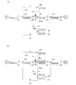
図1は、本発明の第1実施形態における経路探索システム10の概略構成を示す説明図である。本実施形態の経路探索システム10は、サーバ100と自動車に搭載されたカーナビゲーションシステム(カーナビ)200とを備えている。図1には、カーナビ200を搭載した自動車を1台のみ示しているが、経路探索システム10には、複数のカーナビ200および携帯ゲーム機、PND(Personal Navigation Device)、PDA(Personal Digital Assistant)といった様々な携帯端末装置が含まれ得る。
A. First embodiment:
A-1. Information processing system configuration:
FIG. 1 is an explanatory diagram showing a schematic configuration of a
カーナビ200は、GPS受信機201と、表示パネル202と、音声出力部203と、無線通信回路205と、操作部206と、主制御部210と、を備えている。
The
GPS受信機201は、GPS(Global Positioning System/全地球測位システム)を構成する人工衛星を用いて測定したカーナビ200の現在位置(緯度、経度)を特定する出発地点情報を電波によって受信する。
The
表示パネル202は、液晶ディスプレイとこれを駆動する駆動回路とを備えている。表示パネル202としては、液晶ディスプレイに限らず、有機ELディスプレイなど、種々の表示デバイスを採用することが可能である。音声出力部203は、音声を出力するためのスピーカや、これを駆動する駆動回路などから構成される。無線通信回路205は、基地局BSとの間でデータ通信もしくは音声通信を無線によって行なう。操作部206は、テンキーやカーソルキーやタッチパネルなどから構成される入力デバイスである。操作部206は、利用者による到着地点および到着地点に到着するまでに許容できる加算時刻の設定入力等を受け付ける。
The
主制御部210は、カーナビ200の各部を制御する。主制御部210は、CPU211と、RAM212と、ROM213と、を備えている。CPU211は、ROM213に記憶されたプログラムをRAM212にロードして実行することで、後述する種々の処理を実行するための機能を実現する。例えば、主制御部210は、表示パネル202を制御することで、地図画像や推奨経路、現在位置などを表示する。また、主制御部210は、無線通信回路205を制御することで、基地局BSを介して(より詳細には、送受信アンテナ、基地局BS、交換局を介して)、インターネットINT上の情報記憶部110および経路探索部120と通信する。また、主制御部210は、一定時間ごとにGPS受信機201を介してGPSを用いてカーナビ200の現在位置情報を測定して、出発地点情報を生成する。
The
サーバ100は、インターネットINTを介してカーナビ200との通信を行なう通信部102と、情報記憶部110と、経路探索部120と、を備えている。情報記憶部110は、CPU、RAM、ROM、により構成された制御部を有し、情報を記憶する記憶装置118を備えている。記憶装置118は、例えば、ハードディスク装置により構成されている。記憶装置118には、地図情報データベース(DB)114と、ノード別経路情報データベース(DB)115と、が構築されている。
The
地図情報DB114は、例えば、リンク情報およびノード情報、画像データとしての地図画像データを記憶している。リンク情報は、複数の層から構成される階層構造を有している。本実施形態では、リンク情報は、3つの層から構成されており、各リンクは、3つの層のいずれかに分類されて記憶されている。一番下の層であるレベル1には、市街地の道路に相当する複数のリンクが記憶され、真ん中の層であるレベル2には、国道に相当するリンクが記憶され、一番上の層であるレベル3には、高速道路に相当するリンクが記憶されている。なお、リンク情報の階層構造の分類方法は本実施形態の態様に限られず、種々変形可能である。他の実施形態において、例えば、レベル1をさらに二つのレベルに分けて、市街地の道路を車線数に応じて分類するなどしてもよいし、層の数は3つや4つ以外の数であってもよい。
The
ノード別経路情報DB115は、後述する出発地点から到着地点までの経路を探索する際に、経路探索の対象となる予め設定された経路探索範囲内に存在する任意に選択されたノードである特定のノードに付与されたラベルに含まれる情報を記憶する。特定のノードに付与されたラベルに含まれる情報は、出発地点から特定のノードに至る経路までリンクコストの累計値(以下、「コスト累計値」とも呼ぶ)と、当該経路における特定のノードに到着する1つ前の直前ノードに付与されたラベルである直前ラベルと、を含む情報である。特定のノードに付与された複数のラベルの内、最も小さいコスト累計値を有するラベルは、確定ラベルもしくは仮ラベルとして記憶される。特定のノードにおいて、確定ラベルもしくは仮ラベル以外のラベル情報は負けラベルとして記憶される。確定ラベルは、各ノードに記憶された全ての仮ラベルの中で、最小のコスト累計値の仮ラベルになった場合に、仮ラベルから変更されるラベルである。
The node-specific
経路探索部120は、CPU、RAM、ROM、により構成された制御部を有し、ラベル付与部122と、第1経路設定部121と、第2経路設定部125と、を備えている。経路探索部120は、カーナビ200に到着地点が設定され、カーナビ200から出発地点情報が送信されると、通信部102を介して出発地点情報および到着地点情報を受信する。ラベル付与部122は、出発地点および到着地点から順々にノードにラベルを付与する。なお、ノードにラベルを付与する処理の詳細については後述する。
The
第1経路設定部121は、最適経路設定部123と、類似経路設定部124とを有している。最適経路設定部123は、ノードに付与されたラベルに含まれる情報に基づいて、出発地点から到着地点に至る経路の内、コスト累計値が最も小さい経路を最適経路として設定する。類似経路設定部124は、ラベルに含まれる情報と最適経路とに基づいて、出発地点から到着地点に至る類似経路を設定する。類似経路の設定処理の詳細については後述する。第2経路設定部125は、後述する下位層探索処理によって、ノードに付与されたラベルと、最適経路および類似経路と、に基づいて第2の経路を設定する。経路探索部120は、最適経路および類似経路と、第2の経路と、を含む経路情報を通信部102を介してカーナビ200に送信する。なお、最適経路および類似経路は、請求項における第1の経路に相当する。
The first
A−2.マルチラベルダイクストラ法:
図2は、マルチラベルダイクストラ法を用いた経路探索処理の流れを示す説明図である。経路探索処理では、初めに、経路探索部120は、出発地点および到着地点を設定する(ステップS11)。次に、経路探索部120は、出発地点STから到着地点GLへと移動するために許容される時間を表わす許容コストを、最適経路による移動時間に対する許容加算時刻に基づいて設定する(ステップS12)。本実施形態では、許容コストは、100に設定される。次に、ラベル付与部122は、各ノードにラベルを付与し、最適経路決定処理を行なう(ステップS13)。
A-2. Multi-label Dijkstra method:
FIG. 2 is an explanatory diagram showing the flow of route search processing using the multi-label Dijkstra method. In the route search process, first, the
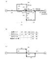
図3は、出発地点STから到着地点GLまでの経路におけるノードとリンクとの一例を示す説明図である。図3には、リンクおよびノードの各名称と、各リンクにおけるリンクコストと、直進禁止表示NGRと、が示されている。マルチラベルダイクストラ法では、各リンクに、進行方向や進行方向の変更に基づいて設定された各種規制を踏まえて、ノードにラベルが付与される。図3に示す全てのリンクは、自動車が走行する道路であり、矢印の方向にしか進めない一方通行の道路であり、逆走やUターンができないように設定されている。例えば、リンクL03では、利用者は、ノードN51からノードN61へと進むことができるが、その逆のノードN61からノードN51へとは進むことができない。直進禁止表示NGRは、リンクL05からノードN61へと入った場合には、ノードN61からリンクL06へとは進めないことを示している。また、図3に示す各ノードにおいては、リンクコストに加えて、左折する場合にはさらに左折コストとして5が加算され、右折する場合にはさらに右折コストとして10が加算されるように設定されている。例えば、L01からノードN51へと入った場合、ノードN51からリンクL02へと進む場合には左折コストが加算され、ノードN51からリンクL04へと進む場合には右折コストが加算される。 FIG. 3 is an explanatory diagram showing an example of nodes and links in the route from the departure point ST to the arrival point GL. FIG. 3 shows the names of links and nodes, the link cost of each link, and the straight travel prohibition display NGR. In the multi-label Dijkstra method, each link is given a label based on various regulations set based on the direction of travel and changes in the direction of travel. All the links shown in FIG. 3 are roads on which automobiles travel, and are one-way roads that can only proceed in the direction of the arrows, and are set so that reverse running and U-turns are not possible. For example, on the link L03, the user can proceed from the node N51 to the node N61, but cannot travel from the opposite node N61 to the node N51. The straight travel prohibition display NGR indicates that, when entering from the link L05 to the node N61, it is not possible to proceed from the node N61 to the link L06. Further, in each node shown in FIG. 3, in addition to the link cost, 5 is added as a left turn cost when making a left turn, and 10 is added as a right turn cost when making a right turn. Yes. For example, when entering from the node L51 to the node N51, a left turn cost is added when going from the node N51 to the link L02, and a right turn cost is added when going from the node N51 to the link L04.
図4から図6までに示す各図は、各ノードにおけるラベルの付与の概略を示す説明図である。マルチラベルダイクストラ法では、各ノードに付与されたラベルの内、最も小さいコスト累計値を含む仮ラベルに着目して、着目されたラベル(以降、「着目ラベル」とも呼ぶ)は確定ラベルとなり、着目ラベルから接続されていると共に通過できるリンクを介する隣接するノードに新たなラベルが付与される。新たに付与されるラベルの情報に含まれるコスト累計値が、同じノードに付与されたラベルであり、かつ、同じ直前ノードを持つラベルの情報に含まれるコスト累計値の内で最も小さい場合には、新たに付与されるラベルは、仮ラベルとして記憶される。一方、新たに付与されるラベルに含まれるコスト累計値が、同じノードに付与され、かつ、同じ直前ノードを持つラベルの情報に含まれるコスト累計値の内で最も小さくない場合には、新たに付与されるラベルは、負けラベルとして記憶される。 Each of the diagrams shown in FIGS. 4 to 6 is an explanatory diagram showing an outline of label assignment in each node. In the multi-label Dijkstra method, paying attention to the temporary label including the smallest accumulated cost value among the labels assigned to each node, the focused label (hereinafter also referred to as “focused label”) becomes a definitive label. A new label is given to an adjacent node via a link that is connected and can pass through the label. When the total cost value included in the newly added label information is the label given to the same node and is the smallest of the total cost values included in the label information having the same previous node The newly assigned label is stored as a temporary label. On the other hand, if the total cost value included in the newly added label is not the smallest of the total cost values included in the label information that is assigned to the same node and has the same previous node, The given label is stored as a losing label.
図4(a)に示すように、最初にラベルの付与を始めるときには、いずれのノードにもラベルが付与されていないため、ラベル付与部122は、出発地点STに仮ラベルであるラベルA0を付与する。ラベルA0には、出発地点STに入る直前ラベルと、コスト累計値と、が記憶されている。ラベルA0では、出発地点STが出発点であり、直前ラベルは存在しないため、直前ラベルは「NULL」と記憶され、コスト累計値は「0」と記憶される。
As shown in FIG. 4A, when labeling is started for the first time, since no label is assigned to any node, the
次に、出発地点STにおける仮ラベルはA0の1つしかないため、ラベルA0が出発地点STにおける確定ラベルとして記憶され、四角形で囲まれて確定ラベルとして表示される。次に、ラベルA0からリンクL01を通過してノードN51へと入る経路のラベルA1が仮ラベルとして記憶される。ラベルA1のコスト累計値には、リンクL01におけるリンクコストの10が加算されて記憶される。図4(a)でラベルA1は、出発地点STからノードN51へと入った方向(右向き)を頂点とした五角形で囲まれて仮ラベルとして表示される。 Next, since there is only one temporary label A0 at the departure point ST, the label A0 is stored as a confirmed label at the departure point ST and is displayed as a confirmed label surrounded by a rectangle. Next, the label A1 of the route from the label A0 through the link L01 to the node N51 is stored as a temporary label. The link cost 10 of the link L01 is added to the cost accumulated value of the label A1 and stored. In FIG. 4A, the label A1 is displayed as a temporary label surrounded by a pentagon with the direction (rightward) from the departure point ST to the node N51 as a vertex.
次に、図4(b)に示すように、ラベルA1は、この時点で各ノードに記憶された全ての仮ラベルの中で、最小のコスト累計値のラベルであるため、ノードN51における確定ラベルとして記憶される。次に、ラベルA1を基準として、ラベルA2、ラベルA3、ラベルA4、が仮ラベルとして記憶される。ラベルA2は、ノードN51からリンクL02を通過してノードN62へと入る経路のラベルである。ラベルA2は、直前ラベルがラベルA1である。ラベルA2のコスト累計値は、リンクL02におけるリンクコストの15と、ノードN51における左折コスト5と、がラベルA1のコスト累計値に加算された30として記憶される。ラベルA3は、ノードN51からリンクL03を通過してノードN61へと入る経路のラベルである。ラベルA3は、直前ラベルがラベルA1である。ラベルA3のコスト累計値は、リンクL03におけるリンクコストの10がラベルA1のコスト累計値に加算された20として記憶される。ラベルA4は、ノードN51からリンクL04を通過してノードN60へと入る経路のラベルである。ラベルA4は、直前ラベルがラベルA1である。ラベルA4のコスト累計値は、リンクL04におけるリンクコストの30と、ノードN51における右折コスト10と、がラベルA1のコスト累計値に加算された50として記憶される。 Next, as shown in FIG. 4B, since the label A1 is the label of the minimum accumulated cost value among all the temporary labels stored in each node at this time, the confirmed label in the node N51. Is remembered as Next, label A2, label A3, and label A4 are stored as temporary labels with reference to label A1. The label A2 is a label of a route that passes from the node N51 through the link L02 and enters the node N62. For label A2, the immediately preceding label is label A1. The accumulated cost value of the label A2 is stored as 30 obtained by adding the link cost 15 of the link L02 and the left turn cost 5 of the node N51 to the accumulated cost value of the label A1. The label A3 is a label of a route that passes from the node N51 through the link L03 to the node N61. For label A3, the immediately preceding label is label A1. The cost accumulated value of the label A3 is stored as 20 in which the link cost 10 in the link L03 is added to the cost accumulated value of the label A1. The label A4 is a label of a route that passes from the node N51 through the link L04 to the node N60. For label A4, the immediately preceding label is label A1. The accumulated cost value of the label A4 is stored as 50 obtained by adding the link cost 30 in the link L04 and the right turn cost 10 in the node N51 to the accumulated cost value of the label A1.
次に、この時点で各ノードに記憶された全ての仮ラベルの中で最小のコスト累計値であるラベルA3が確定ラベルとして記憶されると共に、図5(a)に示すように、ラベルA3を基準として、ラベルA5、ラベルA6、が仮ラベルとして記憶される。ラベルA5は、ノードN61からリンクL06を通過してノードN60へと入る経路のラベルである。ラベルA5は、直前ラベルがラベルA3である。ラベルA5のコスト累計値は、リンクL06におけるリンクコストの10と、ノードN61における右折コスト10と、がラベルA3のコスト累計値に加算された40として記憶される。マルチラベルダイクストラ法では、各ラベルに記憶された直前ラベルの情報に含まれる直前ノードを考慮に入れるため、特定のノードにおいて異なるノードから入った経路のラベルの場合、これらは同一のラベルとしてみなさないため、複数の確定ラベルや仮ラベルが存在する場合がある。そのため、ノードN60において、ラベルA4とラベルA5との2つの仮ラベルが存在している。ラベルA6は、ノードN61からリンクL07を通過してノードN71へと入る経路のラベルである。ラベルA6は、直前ラベルがラベルA3である。ラベルA6のコスト累計値は、リンクL07におけるリンクコストの10がラベルA3のコスト累計値に加算された30として記憶される。 Next, among all the temporary labels stored in each node at this time, the label A3 which is the minimum accumulated cost value is stored as a confirmed label, and as shown in FIG. As a reference, labels A5 and A6 are stored as temporary labels. The label A5 is a label of a route from the node N61 through the link L06 to the node N60. For label A5, the immediately preceding label is label A3. The accumulated cost value of the label A5 is stored as 40 obtained by adding the link cost 10 in the link L06 and the right turn cost 10 in the node N61 to the accumulated cost value of the label A3. In the multi-label Dijkstra method, since the immediately preceding node included in the information of the immediately preceding label stored in each label is taken into consideration, in the case of a label of a route entered from a different node in a specific node, these are not regarded as the same label. Therefore, there may be a plurality of confirmed labels and temporary labels. Therefore, at node N60, there are two temporary labels, label A4 and label A5. The label A6 is a label of a route that passes from the node N61 through the link L07 and enters the node N71. For label A6, the immediately preceding label is label A3. The cost accumulated value of the label A6 is stored as 30 obtained by adding 10 of the link cost in the link L07 to the cost accumulated value of the label A3.
次に、ラベルA2は、この時点で各ノードに記憶された全ての仮ラベルの中で最小のコスト累計値であるため、ノードN62における確定ラベルとして記憶されると共に、図5(b)に示すように、ラベルA2を基準として、ラベルA7が仮ラベルとして記憶される。ラベルA7は、ノードN62からリンクL05を通過してノードN61へと入る経路のラベルである。ラベルA7は、直前ラベルがラベルA2である。ラベルA7のコスト累計値は、リンクL05におけるリンクコストの5がラベルA2のコスト累計値に加算された35として記憶される。ノードN62は、交差点ではなく、道なり方向への通行であるため、ラベルA7のコスト累計値には、右折コストが加算されない。 Next, since the label A2 is the minimum accumulated cost value among all the temporary labels stored in each node at this time, the label A2 is stored as a confirmed label in the node N62 and shown in FIG. 5B. Thus, label A7 is stored as a temporary label with label A2 as a reference. The label A7 is a label of a route that passes from the node N62 through the link L05 to the node N61. For label A7, the immediately preceding label is label A2. The cost accumulated value of the label A7 is stored as 35 obtained by adding 5 of the link cost of the link L05 to the cost accumulated value of the label A2. Since the node N62 is not an intersection but a road, the right turn cost is not added to the accumulated cost value of the label A7.
次に、この時点で各ノードに記憶された全ての仮ラベルの中で最小のコスト累計値のラベルA6が確定ラベルとして記憶されると共に、図6(a)に示すように、ラベルA6を基準として、ラベルA8が仮ラベルとして記憶される。ラベルA8は、ノードN71からリンクL09を通過して到着地点GLへと入る経路のラベルである。ラベルA8は、直前ラベルがラベルA6である。ラベルA8のコスト累計値は、リンクL09におけるリンクコストの10がラベルA6のコスト累計値に加算された40として記憶される。 Next, among all the temporary labels stored in each node at this time, the label A6 having the minimum accumulated cost value is stored as a confirmed label, and the label A6 is used as a reference as shown in FIG. The label A8 is stored as a temporary label. The label A8 is a label of a route that passes from the node N71 through the link L09 and enters the arrival point GL. For label A8, the immediately preceding label is label A6. The cost accumulated value of the label A8 is stored as 40 obtained by adding 10 of the link cost of the link L09 to the cost accumulated value of the label A6.
次に、この時点で各ノードに記憶された全ての仮ラベルの中で最小のコスト累計値のラベルA7が確定ラベルとして記憶されると共に、図6(b)に示すように、ラベルA7を基準として、ノードN61からリンクL07を通過してノードN71へと入る経路のラベルA9が付与される。ラベルA9は、直前ラベルがラベルA7である。ラベルA9のコスト累計値は、リンクL07におけるリンクコストの10と、ノードN61における左折コスト5と、がラベルA7のコスト累計値に加算された50として記憶される。ラベルA9は、ラベルA6と同様に、直前のノードがノードN61であり、ラベルA6のコスト累計値である30よりも大きいため、負けラベルとして記憶される。図6(b)に示すように、負けラベルは、楕円で囲まれて表示される。また、直進禁止表示NGRによって、リンクL05からリンクL06へとは進めないため、この経路に対応したラベルは付与されない。
Next, among all the temporary labels stored in each node at this time, the label A7 having the minimum accumulated cost value is stored as the final label, and the label A7 is used as a reference as shown in FIG. 6B. Is given a label A9 of a route from the node N61 through the link L07 to the node N71. For label A9, the immediately preceding label is label A7. The accumulated cost value of the label A9 is stored as 50 obtained by adding the link cost 10 at the link L07 and the left turn cost 5 at the node N61 to the accumulated cost value of the label A7. Similarly to the label A6, the label A9 is stored as a losing label because the immediately preceding node is the node N61 and is larger than the cost
次に、上述した各ノードにおけるラベルの付与と同じように、確定ラベルとして記憶されたラベルA5を基準としてラベルA10が仮ラベルとして記憶される。次に、ラベルA5とコスト累計値が同じラベルA8が確定ラベルとして記憶され、到着地点GLに確定ラベルが付与される。なお、到着地点GLで確定したラベルA8からは、これ以上どこにも進むことができないため、ラベルA8を基準として新たなラベルは付与されない。到着地点GLに確定ラベルが付与されたため、ラベルA8により最適経路が設定され、最適経路のコスト累計値は40であることが決定する。 Next, similarly to the label assignment at each node described above, the label A10 is stored as a temporary label with the label A5 stored as the confirmed label as a reference. Next, a label A8 having the same cost accumulated value as the label A5 is stored as a confirmed label, and the confirmed label is given to the arrival point GL. In addition, since the label A8 determined at the arrival point GL cannot go any further, no new label is given based on the label A8. Since the final label is assigned to the arrival point GL, the optimum route is set by the label A8, and it is determined that the accumulated cost value of the optimum route is 40.
次に、この時点で各ノードに記憶された全ての仮ラベルの中で最小のコスト累計値のラベルA4に着目すると、ラベルA4のコスト累計値は、50であり、最適経路のコスト累計値40に許容コストの100を加えたコストの140未満を満たす。そのため、ラベルA4が引き続き確定ラベルとして記憶され、ラベルA4を基準としてラベルA11が付与される。しかし、ノードN71に既に存在しているラベルA10は、ラベルA11と同じ直前のノードN60を持つラベルであり、かつ、ラベルA11のコスト累計値の80よりも小さなコスト累計値の65を持っているため、ラベルA11は負けラベルとして記憶される。次に、ノードN71において、ラベルA10が確定ラベルとして記憶され、ラベルA10を基準として、ラベルA12が付与される。これですべての仮ラベルがなくなったことから、ラベルの付与処理が終了する。
Next, paying attention to the label A4 with the minimum cost accumulated value among all the temporary labels stored in each node at this time, the cost accumulated value of the label A4 is 50, and the cost accumulated
図6(c)には、出発地点STから到着地点GLまでの最適経路と、各ノードにおけるラベルと、が示されている。図6(c)では、最適経路として、出発地点STからリンクL01、ノードN51、リンクL03、ノードN61、リンクL07、ノードN71、リンクL09を通過して到着地点GLへと入った経路が、他のリンクよりも太く矢印で示されている。 FIG. 6C shows the optimum route from the departure point ST to the arrival point GL and the labels at each node. In FIG. 6 (c), as the optimum route, the route from the departure point ST through the link L01, the node N51, the link L03, the node N61, the link L07, the node N71, and the link L09 to the arrival point GL It is indicated by an arrow that is thicker than the link.
次に、類似経路設定部124は、最適経路と、各ノードに付与されたラベルに含まれる情報と、に基づいて、コスト累計値が初めに設定した許容コスト100と、最適経路のコスト累計値40を加えたコストの140以下の経路を第2経路として設定する(図2のステップS14)。図7は、類似経路設定処理の流れを示す説明図である。類似経路設定部124は、到着地点GLに負けラベルが記憶されているかを判定する(ステップS21)。到着地点GLに負けラベルが記憶されていると判定された場合には(ステップS21:YES)、類似経路設定部124は、到着地点GLにおける経路別コスト差が許容コストの100以下であるか否かを判定する(ステップS22)。到着地点GLに負けラベルが記憶されていないと判定された場合には(ステップS21:NO)、類似経路設定部124は、到着地点GLにおける類似経路を設定しない。経路別コスト差とは、各ノードに付与された、確定ラベルに含まれるコスト累計値と負けラベルに含まれるコスト累計値との差である。ステップS22の処理において経路別コスト差が許容コスト以下であると判定された場合には(ステップS22:YES)、類似経路設定部124は、到着地点GLにおける類似経路として設定する(ステップS23)。ステップS22の処理において経路別コスト差が許容コストを超えると判定された場合には(ステップS22:NO)、類似経路設定部124は、到着地点GLにおける類似経路を設定しない。
Next, the similar
次に、類似経路設定部124は、最適経路に含まれるノードである最適ノードにおいて、負けラベルの直前のノードが最適ノードである負けラベル(以下、「特定負けラベル」とも呼ぶ)があるか否かを判定する(ステップS24)。図6(c)に示すように、到着地点GLにおける確定ラベルのラベルA8と負けラベルのA12との経路別コスト差である45は、許容コストの100よりも小さいため、類似経路設定部124は、いずれかの最適ノードに特定負けラベルがあるか否かを判定する。特定負けラベルがないと判定された場合(図7のステップS24:NO)、類似経路設定部124は、類似経路設定処理を終了する。特定負けラベルがあると判定された場合(ステップS24:YES)、類似経路設定部124は、最適ノードにおける特定負けラベルと確定ラベルとの経路別コスト差が許容コスト以下であるかを判定する(ステップS25)。
Next, the similar
図6(c)に示すように、到着地点GLにおけるラベルA12と、ノードN71におけるラベルA9およびラベルA11と、が最適ノードにおける負けラベルである。ラベルA12に含まれる直前ラベルは、ラベルA10であり、ラベルA10は最適ノードであるノードN71に付与されたラベルである。ラベルA9に含まれる直前ラベルは、ラベルA7であり、ラベルA7は最適ノードであるノードN61に付与されたラベルである。ラベルA11に含まれる直前ラベルは、ラベルA4であり、ラベルA4は最適ノードではないノードN60に付与されたラベルである。そのため、ラベルA12およびラベルA9は、特定負けラベルであり、ラベルA11は、特定負けラベルではない。 As shown in FIG. 6C, the label A12 at the arrival point GL and the labels A9 and A11 at the node N71 are losing labels at the optimum node. The immediately preceding label included in the label A12 is the label A10, and the label A10 is a label given to the node N71 that is the optimum node. The immediately preceding label included in the label A9 is the label A7, and the label A7 is a label given to the node N61 that is the optimum node. The immediately preceding label included in label A11 is label A4, and label A4 is a label given to node N60 that is not the optimum node. Therefore, label A12 and label A9 are specific loss labels, and label A11 is not a specific loss label.
次に、類似経路設定部124は、最適ノードに付与された特定負けラベルであるラベルA9およびラベルA12における経路別コスト差のそれぞれが許容コスト以下であるか否かを判定する(ステップS25)。ステップS25の処理において特定負けラベルの経路別コスト差が許容コストを超える場合には(ステップS25:NO)、類似経路設定部124は、類似経路設定処理を終了する。到着地点GLにおいて、ラベルA12のコスト累計値は85であり、ラベルA12の最適経路のラベルA8に対する経路別コスト差は45である。ノードN71において、ラベルA9のコスト累計値は50であり、ラベルA9の最適経路を構成するラベルA6に対するラベルA9の経路別コスト差は20である。そのため、これら2つの特定負けラベルの経路別コスト差は、許容コストの100以下であるため(ステップS25:YES)、類似経路設定部124は、ラベルA12に基づいて特定される経路と、ラベルA9に基づいて特定される経路およびリンクL09とを組み合わせた経路と、を類似経路として決定する(ステップS26)。
Next, the similar
図8は、最適ノードにおいて設定された類似経路の概略を示す説明図である。図8(a)には、設定された最適経路および類似経路と、最適経路および類似経路に関連する確定ラベルおよび負けラベルと、が示されている。図8(a)では、最適経路は実線で示され、最適経路と異なる類似経路は点線または一点鎖線で示されている。図8(b)には、各最適ノードにおける確定ラベルと、負けラベルと、経路別コスト差と、が示されている。図8(c)には、最適ノードと類似経路における経路別コスト差とのそれぞれの概略が示されている。 FIG. 8 is an explanatory diagram showing an outline of a similar route set in the optimum node. FIG. 8A shows the set optimal route and the similar route, and the finalized label and the losing label related to the optimal route and the similar route. In FIG. 8A, the optimum route is indicated by a solid line, and a similar route different from the optimum route is indicated by a dotted line or a one-dot chain line. FIG. 8B shows a definite label, a losing label, and a path-specific cost difference at each optimum node. FIG. 8C shows an outline of the optimum node and the cost difference for each route in the similar route.
類似経路設定部124は、類似経路を設定すると(図7のステップS26)、次に、設定した類似経路に類似する準類似経路を設定する。類似経路設定部124は、類似経路に含まれるノードである類似ノードにおいて、負けラベルの直前のノードが類似ノードである負けラベル(以下、「準特定負けラベル」とも呼ぶ)があるか否かを判定する(ステップS27)。なお、最適経路と類似経路との関係によって、最適ノードかつ類似ノードとなるノードも存在する。準特定負けラベルがないと判定された場合には(ステップS27:NO)、類似経路設定部124は、類似経路設定処理を終了する。
When the similar
図9は、最適ノードおよび類似ノードにおいて設定された最適経路および準類似経路の概略を示す説明図である。図9(a)には、設定された最適経路と類似経路と準類似経路と、各経路に関連する確定ラベルおよび負けラベルと、が示されている。最適経路は実線で示され、最適経路と異なる類似経路は点線または一点鎖線で示され、最適経路および類似経路と異なる準類似経路は一点鎖線および二点鎖線で示されている。図9(b)には、最適ノードおよび類似ノードにおける確定ラベル、負けラベル、経路別コスト差、経路加算コスト、が示されている。図9(c)には、準類似経路の経路別コスト差および経路加算コストの概略が示されている。 FIG. 9 is an explanatory diagram showing an outline of the optimum route and the semi-similar route set in the optimum node and the similar node. FIG. 9A shows the set optimum route, similar route, semi-similar route, and a definite label and a losing label related to each route. The optimum path is indicated by a solid line, a similar path different from the optimum path is indicated by a dotted line or a one-dot chain line, and a semi-similar path different from the optimum path and the similar path is indicated by a one-dot chain line and a two-dot chain line. FIG. 9B shows the definite label, the losing label, the cost difference for each route, and the route addition cost at the optimum node and the similar node. FIG. 9C shows an outline of the cost difference for each route of the semi-similar route and the route addition cost.
図9(a)に示すように、準特定負けラベルとなる類似ノードに付与された負けラベルは、ラベルA11である。ラベルA11の直前のノードは、ラベルA12を構成する類似経路に含まれる類似ノードであるため(図7のステップS27:YES)、類似経路設定部124は、差分許容コストが設定した許容コスト以下であるか否かを判定する(ステップS28)。差分許容コストとは、許容コストから、類似経路のリンクコストのコスト累計値から最適経路のリンクコストのコスト累計値を差し引いた値を、差し引いた値である。そのため、ラベルA11の差分許容コストは、類似経路のリンクコストの累計値である85から最適経路のリンクコストのコスト累計値である40を差し引いた45を、許容コストの100から差し引いた55である。ノードN71において、ラベルA12から特定される類似経路のラベルA10と、ラベルA11と、の経路別コスト差は、15であり、差分許容コストの55以下であるため(図7のステップS28:YES)、類似経路設定部124は、ラベルA11から特定される経路を準類似経路として設定する(ステップS29)。次に、類似経路設定部124は、準類似経路を類似経路として設定し(ステップS30)、新たに設定した類似経路に対して準類似経路が設定されなくなるまでステップS27からステップS30までの処理を繰り返す。ステップS28の処理において、該当する負けラベルがないと判定された場合には(ステップS28:NO)、類似経路設定部124は、準類似経路設定処理を終了する。
As shown in FIG. 9A, the losing label given to the similar node that becomes the semi-specific losing label is the label A11. Since the node immediately before the label A11 is a similar node included in the similar route constituting the label A12 (step S27 in FIG. 7: YES), the similar
A−3.経路探索処理:
図10は、本実施形態における経路探索処理の流れを示す説明図である。経路探索処理では、カーナビ200の利用者の出発地点から到着地点に至る経路の内の最適経路および類似経路が探索される。
A-3. Route search process:
FIG. 10 is an explanatory diagram showing the flow of route search processing in the present embodiment. In the route search process, an optimum route and a similar route are searched for from the departure point to the arrival point of the user of the
初めに、サーバ100の経路探索部120は、利用者による自動車のカーナビ200への入力に基づいて、出発地点と、到着地点と、出発地点から到着地点までの経路を移動するために許容される加算時間を表す許容コストと、を取得する(ステップS41)。利用者がカーナビ200に到着地点を入力すると、カーナビ200は、到着地点情報を生成する。また、GPS受信機201は、カーナビ200の現在位置から出発地点情報を生成する。また、利用者がカーナビ200に対し、最適経路での移動時間に対して遅れたとみなさない許容時間範囲を設定することで、経路探索部120は、この許容時間を許容コストとして保持する。なお、出発地点および到着地点のそれぞれは、請求項における第1地点および第2地点に相当する。
First, the
次に、経路探索部120は、階層的経路探索処理を行なう(ステップS42)。階層的経路探索処理では、出発地点STから到着地点GLに至る最適経路および類似経路が設定される。なお、階層的経路探索処理の詳細については後述する。次に、経路探索部120は、階層的経路探索処理において、所定の数以上の類似経路の存在有無を判定する(ステップS43)。所定の数以上の類似経路がないと判定された場合には(ステップS43:NO)、経路探索部120は、下位層追加探索処理を行なう(ステップS44)。なお、下位層追加探索処理の詳細については後述する。ステップS43の処理で所定の数以上の類似経路があると判定された場合(ステップS43:YES)、または、下位層追加探索処理が完了した場合には(ステップS44)、経路探索部120は、経路探索処理を終了する。
Next, the
A−3−1.階層的経路探索処理:
図11は、階層的経路探索処理の流れを示す説明図である。階層的経路探索処理では、リンク情報に記憶されている層に含まれるレベル別のリンクごとに、経路探索を行なう条件を変更して、出発地点から到着地点に至る経路を探索する。
A-3-1. Hierarchical route search processing:
FIG. 11 is an explanatory diagram showing the flow of the hierarchical route search process. In the hierarchical route search processing, the route search condition is changed for each level-level link included in the layer stored in the link information, and the route from the departure point to the arrival point is searched.
初めに、経路探索部120は、出発地点STと到着地点GLとに仮ラベルを付与する(ステップS51)。次に経路探索部120は、経路を探索する層である探索層のレベルを設定する(ステップS52)。本実施形態では、初期値としてレベル1を探索層として設定する。探索層がレベル1に設定されると、経路探索部120は、探索層と、探索層よりも上位の層であるレベル2およびレベル3と、に記憶されている複数のリンク(以下「レベル1リンク群」という。)を探索対象として経路探索を行なう。この場合、リンク情報に記憶された全てのリンクが探索対象となるが、例えば、レベル2が探索層として設定された場合には、レベル2とレベル3とに記憶されたリンク(以下「レベル2リンク群」という。)のみが探索対象となる。また、レベル3が探索層として設定された場合には、レベル3に記憶されたリンク(以下「レベル3リンク群」という。)のみが探索対象となる。以上のように、レベル1リンク群は、レベル2リンク群よりも詳細な詳細度の複数のリンクからなり、レベル2リンク群は、レベル3リンク群よりも詳細な詳細度の複数のリンクからなっている。なお、他の実施形態では、初期値についは種々変形可能である。
First, the
次に、経路探索部120は、探索対象の複数のリンクに接続するノードに対してラベルを付与するループ回数を設定する(ステップS53)。1回のループでは、1つの仮ラベルが付与されたノードに接続する進行可能であるリンクを介して、隣接する全てのノードにラベルが付与される。例えば、あるノードにおける仮ラベルに着目した場合、着目ラベルが付与されたノードが接続する進行可能なリンクが3つある場合には、1回のループによって隣接する各ノードのそれぞれに仮ラベルが付与され、合計として3つのラベルが付与される。経路探索部120は、探索層のレベルに対して予め設定されたループ回数だけノードにラベルを付与する。本実施形態では、レベル1におけるループ回数は、1000回に設定されているが、他の実施形態では異なる回数であってもよい。
Next, the
次に、経路探索部120は、経路導出処理を行なう(ステップS54)。経路導出処理では、ノードにラベルを付与することによって、出発地点STから到着地点GLに至る最適経路を探索する。なお、経路導出処理の詳細については後述する。次に、経路探索部120は、経路導出処理によって、最適経路が設定されたか否かを判定する(ステップS55)。最適経路が設定されていないと判定された場合には(ステップS55:NO)、経路探索部120は、探索層のレベルを1つ上げて、探索層をレベル2に設定する(ステップS56)。その後、経路探索部120は、探索層がレベル2の場合のループ回数を、予め設定された500回に設定し(ステップS53)、ステップS54以降の処理を最適経路が設定されるまで繰り返す。ステップS55の処理において、最適経路が設定されたと判定された場合には(ステップS55:YES)、経路探索部120は、階層的経路探索処理を終了する。
Next, the
A−3−2.経路導出処理:
図12は、経路導出処理の流れを示す説明図である。経路導出処理では、初めに、経路探索部120は、双方向探索において、順探索と逆探索とから一方を選択する(ステップS61)。経路導出処理では、マルチラベルダイクストラ法を用いて、出発地点STから順番にノードにラベルを付与して経路を探索する順探索と同時に、到着地点GLからも順番にノードにラベルを付与して経路を探索する逆探索を行なう双方向探索が行なわれる。経路探索部120は、順探索と逆探索とから一方を選択して、選択した経路探索において、ノードにラベルを付与する。例えば、順探索によって探索されたノードにラベルが付与された場合には、次のラベルの付与では、逆探索によって探索されたノードにラベルが付与される。経路導出処理を始めた初期では、経路探索部120は、初めに、順探索を選択する。
A-3-2. Route derivation process:
FIG. 12 is an explanatory diagram showing the flow of the route derivation process. In the route derivation process, first, the
図13は、双方向探索の概略を示す説明図である。図13には、出発地点STおよび到着地点GLを含む一部の領域のノードとリンクとが示されている。図13に示すように、リンクL13、リンクL14、リンクL17、リンクL18には、進行方向に対して規制が設定されており、これらのリンクでは、利用者は、矢印の向きに沿って各リンクを通過できるが、逆方向に沿って各リンクを通過できない。例えば、リンクL13は、ノードN11からノードN13へと通過できるリンクであるが、ノードN13からノードN11へとは通過できないリンクである。逆探索では、到着地点GLからノードにラベルを付与する場合に、ラベル付与部122は、各リンクに設定された進行方向や右折コスト等の設定を変更してラベルを付与する。例えば、リンクL18は、ノードN18からノードN16へと通過できるリンクであるが、逆探索では、ノードN16からノードN18へと通過できるとリンクとして、ラベルが付与される。また、リンクL16からノードN16を介してリンクL18へと入る場合には、ラベルに含まれるコスト累計値には、左折コストではなく、右折コストが加算される。1回のループでは、出発地点STを出発して付与されたラベル、または、到着地点GLを出発して付与されたラベルのそれぞれの1つの確定ラベルに対して、ラベルの付与が行なわれる。
FIG. 13 is an explanatory diagram showing an outline of the bidirectional search. FIG. 13 shows nodes and links in some areas including the departure point ST and the arrival point GL. As shown in FIG. 13, the link L13, the link L14, the link L17, and the link L18 are set with respect to the traveling direction, and in these links, the user moves each link along the direction of the arrow. Can pass through, but not through each link along the opposite direction. For example, the link L13 is a link that can pass from the node N11 to the node N13, but cannot pass from the node N13 to the node N11. In the reverse search, when assigning a label to the node from the arrival point GL, the
次に、ラベル付与部122は、順探索もしくは逆探索によって付与された仮ラベルがあるか否かを判定する(図12のステップS62)。まだ仮ラベルがある場合には(ステップS62:YES)、経路探索部120は、ノードにラベルを付与したループ回数が設定されたループ回数である1000回よりも大きいか否かを判定する(ステップS63)。最初の時点では、出発地点STおよび到着地点GLに隣接するノードのみにラベルが付与されているため、ラベル付与回数は1000回より小さい(ステップS63:NO)。その場合、経路探索部120は、順探索によって付与された複数の仮ラベルに含まれるコスト累計値の内の最も小さい最小順コストと、逆探索によって付与された複数の仮ラベルに含まれるコスト累計値の内の最も小さい最小逆コストと、を加えた値(以下、「合算コスト累計値」とも呼ぶ)が既に導出されている最適経路のコスト累計値(以下、「導出済最適経路コスト」とも呼ぶ)に許容コストを加えた値よりも大きいか否かを判定する(ステップS64)。なお、ステップS64の処理において、最適経路が設定されておらず、導出済最適経路コストが存在しない場合には、合算コスト累計値が導出済最適経路コストと許容コストとの和よりも小さいと判定される。
Next, the
ステップS64の処理において、条件を満たさない場合には(ステップS64:NO)、ラベル付与部122は、ループ回数を1回増やす(ステップS65)。ラベル付与部122は、ラベルを付与するために、ノードに付与されたラベルに含まれるコスト累計値が最も少ない仮ラベルに着目する(ステップS66)。次に、ラベル付与部122は、着目した仮ラベルを確定ラベルに変更する(ステップS67)。
In the process of step S64, when the condition is not satisfied (step S64: NO), the
次に、経路探索部120は、順探索によって付与されたラベルと逆探索によって付与されたラベルとの順逆両方向のラベルが重複するノードが存在するか否かを判定する(ステップS68)。図14は、ラベルが重複するノードの一例を示す説明図である。図14には、双方向探索が行なわれた場合に、出発地点STから到着地点GLに至る経路に含まれるノードに付与された確定ラベルおよび仮ラベルが示されている。図14(a)には、順探索および逆探索のそれぞれに対してループ回数を増やし、順番にノードにラベルが付与された場合に、順探索によって付与されたラベルと、逆探索によって付与されたラベルと、が重複するノードが示されている。図14(a)において、「順確定」は、順探索によってノードに付与された確定ラベルを意味し、「順仮」は、順探索によってノードに付与された仮ラベルを意味する。また、「逆確定」は、逆探索によってノードに付与された確定ラベルを意味し、「逆仮」は、逆探索によってノードに付与された仮ラベルを意味する。図14(a)に示すように、順探索および逆探索のそれぞれによって順番にノードにラベルが付与されると、リンクL23のように、順探索および逆探索のそれぞれの確定ラベルから特定される経路に含まれるリンクが出現する。この場合に、ノードN22およびノードN23が重複するノードとしてみなされる。図14(b)には、順探索のみに基づいて探索された出発地点STから到着地点GLに至る経路が示されている。この場合に、到着地点GLが重複するノードとしてみなされる。マルチラベルダイクストラ法を用いた双方向探索では、図14(a)または図14(b)に示すようなラベルに基づいて出発地点STから到着地点GLに至る経路が探索される。
Next, the
図12のステップS68の処理において、重複するノードが存在すると判定された場合には(ステップS68:YES)、経路探索部120は、経路接続後処理を行ない(ステップS69)、ステップS61以降の処理を行なう。経路接続後処理では、重複するノードに基づいて経路が設定される。なお、経路接続後処理の詳細については後述する。ステップS68の処理において、重複するノードが存在しないと判定された場合には(ステップS68:NO)、ラベル付与部122は、ラベル付与処理を行ない(ステップS70)、経路探索部120は、ステップS61以降の処理を行なう。ラベル付与処理では、マルチラベルダイクストラ法を用いて、ノードにラベルが付与される。なお、ラベル付与処理の詳細については後述する。
If it is determined in step S68 in FIG. 12 that there is an overlapping node (step S68: YES), the
ステップS62の処理において仮ラベルがないと判定された場合と(ステップS62:NO)、ステップS63の処理においてループ回数が設定されたループ回数よりも多いと判定された場合と(ステップS63:YES)、合算コスト累計値が導出済最適経路コストと許容コストとの和よりも大きいと判定された場合とには(ステップS64:YES)、経路探索部120は、ノードに付与された負けラベルが存在するか否かを判定する(ステップS71)。ノードに付与された負けラベルが存在すると判定された場合には(ステップS71:YES)、類似経路設定部124は、負けラベルが付与されている確定ラベルと負けラベルとに含まれるコスト累計値の差に基づいて、最適経路のコスト累計値に許容コストを加えた値以下のコスト累計値となる類似経路を設定し(ステップS72)、経路探索部120は、経路導出処理を終了する。また、ステップS71の処理において、ノードに付与された負けラベルがないと判定された場合には(ステップS71:NO)、経路探索部120は、経路導出処理を終了する。
When it is determined in step S62 that there is no temporary label (step S62: NO), when it is determined in step S63 that the number of loops is greater than the set loop number (step S63: YES). When it is determined that the total accumulated cost is greater than the sum of the derived optimal route cost and the allowable cost (step S64: YES), the
A−3−3.経路接続後処理:
図15は、経路接続後処理の流れを示す説明図である。経路接続後処理では、双方向探索によって、順探索および逆探索のそれぞれによって付与されたラベルが重複するノードがある場合に、重複するノードに付与された2つのラベルに基づいて経路が設定される。初めに、経路探索部120は、重複するノードに付与されたラベルに基づいて、出発地点STから到着地点GLに至る経路のコスト累計値を算出する(ステップS81)。
A-3-3. Post-route processing:
FIG. 15 is an explanatory diagram showing the flow of post-path connection processing. In the post-route connection processing, when there are nodes with overlapping labels assigned by the forward search and the reverse search, the route is set based on the two labels assigned to the overlapping nodes. . First, the
図16は、重複するノードに付与された確定ラベルに含まれるコスト累計値の一例を示す説明図である。図16に示すように、順探索と逆探索とによって、ノードN22およびノードN23が重複するノードに該当する。この場合に、経路探索部120は、出発地点STから到着地点GLに至る経路のコスト累計値を、ノードN23において順探索によって付与された確定ノードに含まれるコスト累計値の40と、ノードN22において逆探索によって付与された確定ノードに含まれるコスト累計値の60と、の和に、重複するリンクL23のリンクコストの10を差し引いた値として算出する。
FIG. 16 is an explanatory diagram showing an example of the accumulated cost value included in the confirmed label given to the overlapping node. As illustrated in FIG. 16, the node N22 and the node N23 correspond to the overlapping nodes by the forward search and the reverse search. In this case, the
確定した経路のコスト累計値が算出されると、経路探索部120は、算出したコスト累計値が導出済最適経路コストと許容コストとを加えた値以下であるか否かを判定する(図15のステップS82)。算出したコスト累計値がステップS82の処理における条件を満たさないと判定された場合には(ステップS82:NO)、経路探索部120は、経路接続後処理を終了する。算出したコスト累計値がステップS82の処理における条件を満たすと判定された場合には(ステップS82:YES)、経路探索部120は、確定した経路を、出発地点STから到着地点GLに至る候補経路として記憶する(ステップS83)。次に、経路探索部120は、新たに記憶した候補経路のコスト累計値が、既に記憶していた候補経路の内で、最小であるか否かを判定する(ステップS84)。新たに記憶した候補経路のコスト累計値が候補経路の内で最小ではないと判定された場合(ステップS84:NO)、経路探索部120は、経路接続後処理を終了する。新たに記憶した候補経路のコスト累計値が候補経路の内で最小であると判定された場合には(ステップS84:YES)、経路探索部120は、新たに記憶した候補経路を導出済最適経路に設定し、導出済最適経路コストを更新する(ステップS85)。次に、経路探索部120は、更新後の導出済最適経路コストに基づいて、候補経路を更新し(ステップS86)、経路接続後処理を終了する。
When the accumulated cost value of the determined route is calculated, the
図17および図18は、候補経路および導出済最適経路の更新の概略を示す説明図である。図17には、新たに確定した経路が候補経路として記憶される前に、記憶されている複数の候補経路の一例が示されている。図17に示すように、候補経路として、経路R01、経路R02、経路R03が記憶されており、最小のコスト累計値の30を有する経路R01が導出済最適経路として記憶されている。許容コストが30に設定されているため、導出済最適経路コストと許容コストとの和は、60である。 FIG. 17 and FIG. 18 are explanatory diagrams showing an outline of updating candidate routes and derived optimum routes. FIG. 17 shows an example of a plurality of candidate routes stored before a newly determined route is stored as a candidate route. As shown in FIG. 17, a route R01, a route R02, and a route R03 are stored as candidate routes, and a route R01 having a minimum accumulated cost value of 30 is stored as a derived optimum route. Since the allowable cost is set to 30, the sum of the derived optimum route cost and the allowable cost is 60.
図18には、新たに確定した経路R04が候補経路として記憶された後に、更新された候補経路の一例が示されている。図18(a)には、経路R04のコスト累計値が40の場合が示されており、図18(b)には、経路R04のコスト累計値が120の場合が示されており、図18(c)には、経路R04のコスト累計値が20の場合が示されている。図18(a)に示すように、経路R04のコスト累計値が40の場合には、経路R04が新たな候補経路として記憶され、経路R01,R02,R03も候補経路として記憶され続ける。図18(b)に示すように、経路R04のコスト累計値が120の場合には、経路R04は、図17に示す導出済最適経路コストと許容コストとの和である60以下でないため、候補経路として記憶されない。図18(c)に示すように、経路R04のコスト累計値が20の場合には、経路R04は、新たな候補経路として記憶されると共に、候補経路の内でコスト累計値が最も小さいため、導出済最適経路として記憶される。経路R04が導出済最適経路として記憶されると、導出済最適経路コストと許容コストとの和が50となり、コスト累計値が60である経路R02は、候補経路から除外される。 FIG. 18 shows an example of a candidate route updated after the newly determined route R04 is stored as a candidate route. FIG. 18A shows a case where the accumulated cost value of the route R04 is 40, and FIG. 18B shows a case where the accumulated cost value of the route R04 is 120. (C) shows a case where the accumulated cost value of the route R04 is 20. As shown in FIG. 18A, when the cost total value of the route R04 is 40, the route R04 is stored as a new candidate route, and the routes R01, R02, and R03 are also continuously stored as candidate routes. As shown in FIG. 18B, when the total cost value of the route R04 is 120, the route R04 is not less than 60, which is the sum of the derived optimum route cost and the allowable cost shown in FIG. Not memorized as a route. As shown in FIG. 18C, when the accumulated cost value of the route R04 is 20, the route R04 is stored as a new candidate route and the accumulated cost value is the smallest among the candidate routes. It is stored as a derived optimum route. When the route R04 is stored as the derived optimum route, the sum of the derived optimum route cost and the allowable cost is 50, and the route R02 having a cumulative cost value of 60 is excluded from the candidate routes.
A−3−4.ラベル付与処理:
図19は、ラベル付与処理の流れを示す説明図である。ラベル付与処理では、マルチラベルダイクストラ法を用いて、ノードにラベルが付与される。初めに、ラベル付与部122は、確定ラベルへ変更された着目ラベルが付与されたノードからリンクを介して進行可能なノードを検出する(ステップS91)。ラベル付与部122は、検出したノードに既にラベルが付与されているか否かを判定する(ステップS92)。検出したノードにラベルが付与されていないと判定された場合には(ステップS92:NO)、ラベル付与部122は、検出したノードに新たなラベルを仮ラベルとして付与し(ステップS93)、ラベル付与処理を終了する。
A-3-4. Labeling process:
FIG. 19 is an explanatory diagram showing the flow of the labeling process. In the label assignment process, a label is assigned to a node using the multi-label Dijkstra method. First, the
ステップS92の処理において、検出したノードに既にラベルが付与されていると判定された場合には(ステップS92:YES)、ラベル付与部122は、既に付与されているラベルの中に確定ラベルが存在するか否かを判定する(ステップS94)。既に付与されているラベルの中に確定ラベルが存在しない場合は(ステップS94:NO)、既に付与されているラベルの中に仮ラベルが必ず存在するため、検出ノードに付与する新たなラベルに含まれるコスト累計値と、既に付与されている仮ラベルに含まれるコスト累計値と、を比較し(ステップS95)、新たなラベルに含まれるコスト累計値の方が小さい場合には(ステップS95:YES)、既に付与されている仮ラベルを負けラベルへ変更するとともに(ステップS96)、新たなラベルを仮ラベルとして付与する(ステップS93)。新たなラベルに含まれるコスト累計値の方が、既に付与されている仮ラベルに含まれるコスト累計値より大きい場合には(ステップS95:NO)、新たなラベルを負けラベルとして付与する(ステップS97)。既に付与されているラベルの中に確定ラベルが存在する場合は(ステップS94:YES)、検出ノードに付与する新たなラベルに含まれるコスト累計値から、既に付与されている確定ラベルに含まれるコスト累計値を差し引いた値が、導出済経路最適コストと許容コストと和未満か否かを判定する(ステップS98)。ステップS98の処理における条件を満たすと判定された場合には(ステップS98:YES)、ラベル付与部122は、検出したノードに新たなラベルを負けラベルとして付与し(ステップS97)、ラベル付与処理を終了する。ステップS98の処理における条件を満たさないと判定された場合には(ステップS98:NO)、ラベル付与部122は、検出ノードにラベルを付与しないでラベル付与処理を終了する。
In the process of step S92, when it is determined that a label is already assigned to the detected node (step S92: YES), the
A−3−5.下位層追加探索処理:
経路探索処理において、所定の数以上の類似経路がないと判定された場合には(図10のステップS43:NO)、経路探索部120は、下位層追加探索処理を行なう(ステップS44)。図20は、下位層追加探索処理の流れを示す説明図である。下位層追加探索処理では、出発地点STから到着地点GLに至る経路が少なくとも1つ設定された場合に、探索層のレベルを1つ下げてラベルが付与され、経路探索が行なわれる。初めに、経路探索部120は、経路探索を行なう探索層のレベルを1つ下げる。例えば、探索層がレベル2の場合に出発地点STから到着地点GLに至る経路が設定された場合には、探索層をレベル1に変更する。次に、ラベル付与部122は、仮ラベル追加処理を行なう(ステップS102)。
A-3-5. Lower layer additional search processing:
In the route search process, when it is determined that there are no more than a predetermined number of similar routes (step S43: NO in FIG. 10), the
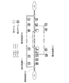
図21から図24までの各図は、仮ラベル追加処理においてノードに付与された仮ラベルの一例を示す説明図である。図21には、出発地点STから到着地点GLに至る最適経路R10、類似経路R11、類似経路R12と、第2の経路R13と、第2の経路R14と、各経路に含まれるリンクおよびノードと、各ノードに付与された確定ラベルおよび仮ラベルと、が示されている。図21では、各経路に含まれるリンクが分類されている層のレベルに基づいて、線種が変更されて示されている。図21に示すように、下位層追加探索処理以外のリンクについて、レベル1リンク群は実線、レベル2リンク群は点線、レベル3リンク群は一点鎖線で示されている。また、最適経路R10は、太線で示され、類似経路R11および類似経路R12は、最適経路R10よりも細い線で示されている。各ノードに付与された確定ラベルは、中が黒で塗りつぶされた五角形で示され、仮ラベルは中が白抜きの五角形で示されている。なお、順探索によって付与された確定ラベルおよび仮ラベルは、五角形の頂点が出発地点STから到着地点GLの方に向いており、逆探索によって付与された確定ラベルおよび仮ラベルは、五角形の頂点が到着地点GLから出発地点STへの方に向いている。下位層追加探索処理では、第2経路設定部125は、最適経路R10と、ノードに付与されたラベルと、に基づいて、第2の経路R13および第2の経路R14を設定する。
Each of FIGS. 21 to 24 is an explanatory diagram showing an example of a temporary label given to a node in the temporary label addition process. FIG. 21 shows an optimum route R10, a similar route R11, a similar route R12, a second route R13, a second route R14, links and nodes included in each route from the departure point ST to the arrival point GL. The fixed label and temporary label assigned to each node are shown. In FIG. 21, the line type is changed based on the level of the layer into which the links included in each route are classified. As shown in FIG. 21, for links other than the lower layer additional search process, the
図21から図24までの各図に示す仮ラベル追加処理では、探索層がレベル3のときに最適経路が出現している。図21に示す仮ラベル処理では、ラベル付与部122は、最適経路R10に含まれるレベル2リンク群に接続するノードに仮ラベルを付与する。すなわち、下位層追加探索処理では、第2経路設定部125は、仮ラベルが付与された最適経路R10に含まれるレベル2リンク群に接続するノードを起点とするとともに、点線および一点鎖線の部分についてレベル2リンク群を経路導出処理(A−3−2)することにより、第2の経路R13および第2の経路R14を探索する。この場合、最適経路R10に含まれるレベル2リンク群に接続するノードを起点として当該経路導出処理をすることにより、階層的経路探索処理(図10のステップS42)のときにレベル3リンク群を探索した部分領域(以下「所定の部分領域」という。)について全てのリンクを探索するのではなく、探索するリンクを制限している。なお、本実施形態におけるレベル3リンク群は、請求項における第1のリンク群に相当し、本実施形態におけるレベル2リンク群は、請求項における第2のリンク群に相当する。
In the temporary label addition processing shown in each of FIGS. 21 to 24, the optimum route appears when the search layer is level 3. In the temporary label process shown in FIG. 21, the
図22から図24までの各図に示す仮ラベル追加処理は、図21と比較して、仮ラベルを付与する条件が異なるため、第2経路設定部125が設定する第2の経路が異なり、他は、図21に示す仮ラベル追加処理と同じである。図22に示す仮ラベル追加処理では、ラベル付与部122は、図21に示す仮ラベル処理と同様に、最適経路R10に含まれるレベル2リンク群に接続するノードに仮ラベルを付与する。さらに、ラベル付与部122は、最適経路R10から分岐する経路であり、分岐するノードがレベル3の探索層よりも1つ下のレベル2リンク群と接続している類似経路R12に含まれるノードにも仮ラベルを付与する。そのため、図22に示すように、第2経路設定部125は、類似経路R12に含まれるノードに付与された仮ラベルに基づいて、さらに第2の経路R15を設定する。
The provisional label addition process shown in each figure from FIG. 22 to FIG. 24 is different from the condition in FIG. 21 in providing the provisional label, so the second route set by the second
図23に示す仮ラベル追加処理では、ラベル付与部122は、最適経路R10と、類似経路R11と、類似経路R12とに含まれるレベル2リンク群に接続する全てのノードに仮ラベルを付与する。そのため、図23に示す例では、図21に示す例と異なり、第2経路設定部125は、類似経路R11に含まれるノードに付与された仮ラベルに基づいて、さらに第2の経路R16を設定する。
In the temporary label addition process shown in FIG. 23, the
図24に示す仮ラベル追加処理では、ラベル付与部122は、最適経路R10に含まれると共に、類似経路R11および類似経路R12には含まれないノードに仮ラベルを付与する。そのため、図24に示す例では、図21に示す例と異なり、第2経路設定部125は、第2の経路R13を設定せずに、第2の経路R14のみを設定する。
In the temporary label addition process shown in FIG. 24, the
A−4.探索経路提示:
図25は、利用者に提示される出発地点STから到着地点GLに至る経路の一例を示す説明図である。図25には、経路探索処理によって設定された、最適経路R20と、最適経路とは異なる複数の経路である非最適経路R21,R22,R23,R24,R25と、が示されている。なお、非最適経路は、類似経路と第2の経路とを含む経路である。例えば、非最適経路R21は、出発地点STからノードN3までが最適経路R20と同じ経路で、ノードN3で最適経路R20からはずれてノードN10を通過し、ノードN4で最適経路R20に合流して、ノードN4から到着地点GLまでは最適経路R20と同じ経路である。なお、ノードN4とノードN5とを結ぶリンクに非最適経路R21が重複されて示されているのは、マルチラベルダイクストラ法を用いて非最適経路R21が設定されたためである。非最適経路R21と同じように、非最適経路R22および非最適経路R25では、ノードN6と到着地点GLとを結ぶリンクは、最適経路R20と重複している。また、非最適経路R23は、非最適経路R22に基づいて設定された非最適経路であるため、ノードN7とノードN8とを結ぶリンクは、非最適経路R22と非最適経路R23とで重複している。なお、非最適経路R24は、最適経路R20と異なるリンクを経由して到着地点GLへ直接合流しているため、合流地点で最適経路R20および他の非最適経路と重複するリンクを含んでいない。
A-4. Search route presentation:
FIG. 25 is an explanatory diagram showing an example of a route from the departure point ST to the arrival point GL presented to the user. FIG. 25 shows an optimum route R20 set by route search processing and non-optimal routes R21, R22, R23, R24, and R25, which are a plurality of routes different from the optimum route. Note that the non-optimal route is a route including a similar route and a second route. For example, the non-optimal route R21 is the same route as the optimum route R20 from the departure point ST to the node N3, deviates from the optimum route R20 at the node N3, passes through the node N10, and joins the optimum route R20 at the node N4. The route from the node N4 to the arrival point GL is the same route as the optimum route R20. The reason why the non-optimal route R21 is shown overlapping the link connecting the node N4 and the node N5 is that the non-optimal route R21 is set using the multi-label Dijkstra method. As in the non-optimal route R21, in the non-optimal route R22 and the non-optimal route R25, the link connecting the node N6 and the arrival point GL overlaps with the optimum route R20. Further, since the non-optimal route R23 is a non-optimal route set based on the non-optimal route R22, the link connecting the node N7 and the node N8 overlaps with the non-optimal route R22 and the non-optimal route R23. Yes. Note that the non-optimal route R24 directly joins the arrival point GL via a link different from the optimum route R20, and therefore does not include a link overlapping the optimum route R20 and other non-optimal routes at the joining point.
経路探索部120は、予め定められた設定や使用者の操作によって、経路探索処理によって設定された経路情報をカーナビ200に送信する。例えば、最適経路R20に対するコスト累計値の差が小さい経路を提示する場合には、経路探索部120は、最適経路R20に対するコスト累計値の差が小さい順に、所定の数の非最適経路を提示する。また、最適経路R20に対して、できるだけ異なる経路、すなわち、最適経路R20に含まれるリンクと重複しない経路を提示する場合には、非最適経路R24、非最適経路R23およびノードN8とノードN6を結ぶリンクを含む経路、ノードN1とノードN9とを結ぶリンクおよび非最適経路R25を含む経路、を提示する。
The
以上説明したように、本実施形態におけるサーバ100では、図21に示すように、レベル2の層を探索層として経路探索を行ない、ラベル付与部122が探索結果に基づいて出発地点STから到着地点GLに至る最適経路R10を設定する。下位層追加探索処理によって、第2経路設定部125は、第2の経路R13,R14,R15,R16を探索する場合に、探索するリンクを制限し、最適経路R10または類似経路R11,R12と少なくとも一部のノードまたはリンクが異なる類似経路R11,R12を設定する。そのため、本実施形態におけるサーバ100では、最適経路R10および類似経路R11,R12の探索結果に基づいて第2の経路R13,R14,R15,R16が設定されるため、最適経路R10および類似経路R11,R12とは異なる経路が設定される場合に、出発地点STから到着地点GLに至る経路を再探索する必要がなく、第2の経路R13,R14,R15,R16が効率良く設定される。また、本実施形態のサーバ100では、下位層追加探索処理によって、第2経路設定部125は、最適経路R10および類似経路R11,R12が設定された際の探索層よりも下位の層に記憶されたリンクを用いた第2の経路を設定できる。つまり、所定の部分領域について、上位の層に記録されたリンクのみで探索した場合、探索される経路数が少ないが、その領域について、下位の層に記憶されたリンクを用いて探索しているので、探索する経路の選択肢をあまり限定されない。一方、下位の層に記憶されたリンクを探索する場合、探索するリンクがより詳細になるため探索に時間がかかることになるが、探索するリンクを制限することにより探索時間の増大を抑制することができる。
As described above, in the
また、本実施形態におけるサーバ100では、図21に示すように、仮ラベル処理では、最適経路R10および類似経路R11,R12に含まれるレベル2リンク群のリンクに接続するノードにラベルが付与され、第2経路設定部125は、付与された仮ラベルに基づいて、第2の経路R13,R14,R15,R16を設定する。そのため、本実施形態におけるサーバ100では、最適経路R10および類似経路R11,R12に含まれるノードを起点として第2の経路R13,R14,R15,R16が探索されるので、第2の経路をより効率良く設定できる。
Further, in the
また、本実施形態におけるサーバ100では、所定の数以上の類似経路がないと判定された場合には(図10のステップS43:NO)、下位層追加探索処理が行なわれ(ステップS44)、類似経路設定部124は、類似経路を設定する(図12のステップS72)。そのため、本実施形態におけるサーバ100では、十分な数の類似経路が探索されて設定されている場合には、第2の経路が設定されないため、経路探索の処理を抑制でき、かつ、迅速に出発地点STから到着地点GLに至る経路を探索できる。
In addition, in the
また、本実施形態におけるサーバ100では、出発地点STを起点とする順探索と、到着地点GLを起点とする逆探索と、を含む双方向探索が行なわれる。各リンクには、進行方向に対して規制が設定されており、逆探索では、各リンクに設定された進行方向や右折コスト等の設定が変更される。双方向探索によって、順探索および逆探索のそれぞれによって探索された経路に含まれる重複するノードがある場合に、最適経路設定部123および類似経路設定部124は、重複するノードを含み、順探索によって探索された経路と、逆探索によって探索された経路と、に基づいて最適経路や類似経路を設定する。そのため、本実施形態におけるサーバ100では、双方向探索によって出発地点STから到着地点GLに至る経路を探索するため、効率良く、かつ、迅速に出発地点STから到着地点GLに至る経路を探索できる。
Further, in the
また、本実施形態におけるサーバ100では、ラベル付与部122は、出発地点および到着地点から順々にノードに、出発地点から特定のノードに至る経路までコスト累計値と、当該経路における特定のノードに到着する1つ前の直前ノードに付与されたラベルである直前ラベルと、を含む情報ラベルを付与する。最適経路設定部123は、ノードに付与されたラベルに含まれる情報に基づいて、出発地点から到着地点に至る経路の内、コスト累計値が最も小さい経路を最適経路として設定する。類似経路設定部124は、ラベルに含まれる情報と、最適経路と、許容コストと、に基づいて出発地点STから到着地点GLに至る類似経路を設定する。そのため、本実施形態におけるサーバ100では、コスト累計値が最も小さい経路と、探索時に付与されたラベルと、に基づいて類似経路が設定されるため、1つの経路が設定された後に、再度、出発地点STから到着地点GLに至るノードへのラベルの付与が不要であり、コスト累計値が小さい経路を効率良く設定できる。
Further, in the
B.第2実施形態:
第2実施形態では、上記実施形態における探索経路提示(図25)によって提示された最適経路R20および複数の非最適経路に対して、さらに情報を付加した経路情報を利用者に提示する。図26は、利用者に提示される出発地点STから到着地点GLに至る経路一覧の一例を示す説明図である。図26には、出発地点STから到着地点GLに至る各経路に対して、分岐ノードと、合流ノードと、合流先と、構成ノードと、が一覧で示されている。分岐ノードは、最適経路R20から、最適経路R20とは異なるリンクを通過する場合に起点となるノードである。合流ノードは、最適経路R20とは異なるリンクを通過した後に、最適経路R20または他の非最適経路に合流するノードである。合流先は、合流ノードで合流した後に、同じノードおよびリンクを通過する最適経路R20または他の非最適経路である。構成ノードは、出発地点STから到着地点GLに至る経路において、通過する順番に沿って表示されたノードである。例えば、非最適経路R23は、ノードN1で最適経路R20から分岐して、ノードN7で非最適経路R22と合流する経路であり、出発地点ST、ノードN1、ノードN7、ノードN8、ノードN6、到着地点GLのノードを通過する。
B. Second embodiment:
In the second embodiment, route information obtained by adding information to the optimum route R20 and the plurality of non-optimal routes presented by the search route presentation (FIG. 25) in the above embodiment is presented to the user. FIG. 26 is an explanatory diagram showing an example of a route list from the departure point ST to the arrival point GL presented to the user. In FIG. 26, for each route from the departure point ST to the arrival point GL, a branch node, a merge node, a merge destination, and a configuration node are shown in a list. A branch node is a node that becomes a starting point when passing through a link different from the optimum route R20 from the optimum route R20. The joining node is a node that joins the optimum route R20 or another non-optimal route after passing through a link different from the optimum route R20. The joining destination is the optimum route R20 or other non-optimal route that passes through the same node and link after joining at the joining node. The constituent nodes are nodes that are displayed along the order of passage in the route from the departure point ST to the arrival point GL. For example, the non-optimal route R23 is a route that branches from the optimum route R20 at the node N1 and merges with the non-optimal route R22 at the node N7. The departure point ST, the node N1, the node N7, the node N8, the node N6, and the arrival Pass the node at point GL.
図27は、第2実施形態における出発地点STから到着地点GLに至る経路の一例を示す説明図である。図27には、ノードN3とノードN4とを結ぶリンクと、ノードN9とノードN5とを結ぶリンクと、において、事故が起きて渋滞ax1,ax2が発生している状態が示されている。図28は、第2実施形態における出発地点STから到着地点GLに至る経路一覧の一例を示す説明図である。図28(a)には、利用者が乗車する自動車の現在位置がノードN1である場合の経路情報の一覧が示されている。渋滞ax1および渋滞ax2の発生は、構成ノードに表示される。最適経路R20に渋滞axが発生している場合に、サーバ100は、渋滞ax1を回避するための経路情報を提示する。図28(a)に示すように、非最適経路R24には渋滞ax2が発生しているため、サーバ100は、非最適経路R24を通行すると渋滞ax2に巻き込まれることを提示する。
FIG. 27 is an explanatory diagram illustrating an example of a route from the departure point ST to the arrival point GL in the second embodiment. FIG. 27 shows a state in which traffic accidents ax1 and ax2 occur due to an accident at the link connecting the node N3 and the node N4 and the link connecting the node N9 and the node N5. FIG. 28 is an explanatory diagram illustrating an example of a route list from the departure point ST to the arrival point GL in the second embodiment. FIG. 28A shows a list of route information when the current position of the vehicle on which the user gets is the node N1. The occurrence of the traffic jam ax1 and the traffic jam ax2 is displayed on the constituent nodes. When the traffic jam ax occurs in the optimal route R20, the
図28(b)には、利用者が乗車する自動車の現在位置がノードN2である場合の経路情報の一覧が示されている。図28(a)に示す例と同じように、サーバ100は、非最適経路R24を通行すると渋滞ax2に巻き込まれることを提示する。また、図28(b)に示すように、自動車の現在位置がノードN2であるため、サーバ100は、ノードN1を分岐ノードとする非最適経路R23および非最適経路R25の経路を通行できないことを提示する。そのため、第2実施形態におけるサーバ100では、出発地点STから到着地点GLに至る経路に発生した渋滞ax1,ax2等に基づいて、利用者に提示する経路情報を変更するため、利用者の利便性が向上する。
FIG. 28B shows a list of route information when the current position of the vehicle on which the user gets is the node N2. As in the example illustrated in FIG. 28A, the
C.変形例:
なお、この発明は上記の実施例や実施形態に限られるものではなく、その要旨を逸脱しない範囲において種々の態様において実施することが可能であり、例えば次のような変形も可能である。
C. Variations:
The present invention is not limited to the above-described examples and embodiments, and can be implemented in various modes without departing from the gist thereof. For example, the following modifications are possible.
C1.変形例1:
上記実施形態では、経路導出処理において、類似経路の設定が行なわれたが(図12のステップS72)、必ずしも類似経路の設定が行なわれなくてもよい。例えば、順探索と逆探索とによって、重複するノードが出現した場合に、重複するノードを含む出発地点STから到着地点GLに至る経路を設定し、設定された経路に基づいて下位層追加探索処理が行なわれて、第2の経路が設定されてもよい。また、上記実施形態では、仮ラベルが付与された最適経路(図21のR10)に含まれるレベル2リンク群に接続するノードを起点とするとともに、所定の部分領域について、レベル2リンク層を経路導出処理(A−3−2)する場合に探索するリンクを制限しているが、他の方法で探索するリンクを制限してもよい。例えば、下位層追加探索処理のときに、所定の部分領域のうち最適経路から所定の距離範囲の複数のリンクのみを探索することにより、探索するリンクを制限するようにしてもよい。
C1. Modification 1:
In the above embodiment, the similar route is set in the route derivation process (step S72 in FIG. 12), but the similar route need not necessarily be set. For example, when an overlapping node appears by forward search and reverse search, a route from the departure point ST including the overlapping node to the arrival point GL is set, and lower layer additional search processing is performed based on the set route And the second route may be set. Moreover, in the said embodiment, while starting from the node connected to the
また、上記実施形態では、ラベル付与処理において、検出したノードに既に確定ラベルが付与されていると判定された場合には(図19のステップS94:YES)、ラベル付与部122は、ステップS98の処理を行なったが、必ずしもステップS98の処理が行なわれなくてもよい。例えば、単に、検出したノードに既に確定ラベルが付与されている場合には(ステップS94:YES)、検出したノードにラベルを付与しない態様であってもよい。
In the above embodiment, if it is determined in the labeling process that a confirmed label has already been assigned to the detected node (step S94 in FIG. 19: YES), the
また、上記実施形態では、マルチラベルダイクストラ法を用いた双方向探索によって、出発地点STから到着地点GLに至る経路が探索されたが、必ずしも双方向探索によって、経路探索が行なわれなくてもよい。単純に、順探索のみのマルチラベルダイクストラ法によって、経路探索が行なわれてもよい。 In the above embodiment, the route from the departure point ST to the arrival point GL is searched by the bidirectional search using the multi-label Dijkstra method. However, the route search may not necessarily be performed by the bidirectional search. . The route search may be performed simply by the multi-label Dijkstra method with only forward search.
C2.変形例2:
上記実施形態では、利用者がカーナビ200の操作部206を操作することにより、到着地点GLを設定したが、到着地点GLおよび各種設定の入力手段はこれに限られず、種々変形可能である。例えば、カーナビ200が利用者の音声入力を受け付ける音声入力部を備えており、音声によって到着地点GLの設定等、各種設定が行なわれてもよい。
C2. Modification 2:
In the above embodiment, the arrival point GL is set by the user operating the
また、上記実施形態では、図1に示すようにサーバ100が情報記憶部110および経路探索部120を備える態様としたが、情報記憶部110および経路探索部120を備える装置はこの態様に限られず、種々変形可能である。例えば、情報記憶部110と経路探索部120とは異なるサーバに備えられていてもよいし、経路探索部120がカーナビ200に搭載されていてもよい。また、経路探索部120におけるラベル付与部122と、第1経路設定部121と、第2経路設定部125とがそれぞれ異なるサーバ100に備えられていてもよい。また、地図情報DB114とノード別経路情報DB115とが同じデータベースに記憶されていてもよい。
In the above embodiment, the
本発明は、上記実施形態や変形例に限られるものではなく、その趣旨を逸脱しない範囲において種々の構成で実現することができる。例えば、発明の概要の欄に記載した各形態中の技術的特徴に対応する実施形態、変形例中の技術的特徴は、上述の課題の一部または全部を解決するために、あるいは、上述の効果の一部または全部を達成するために、適宜、差し替えや、組み合わせを行なうことが可能である。また、その技術的特徴が本明細書中に必須なものとして説明されていなければ、適宜、削除することが可能である。 The present invention is not limited to the above-described embodiments and modifications, and can be realized with various configurations without departing from the spirit of the present invention. For example, the technical features in the embodiments and the modifications corresponding to the technical features in each form described in the summary section of the invention are to solve some or all of the above-described problems, or In order to achieve part or all of the effects, replacement or combination can be performed as appropriate. Further, if the technical feature is not described as essential in the present specification, it can be deleted as appropriate.
10…経路探索システム
100…サーバ
102…通信部
110…情報記憶部
114…地図情報DB
115…ノード別経路情報DB
118…記憶装置
120…経路探索部
121…第1経路設定部
122…ラベル付与部
123…最適経路設定部
124…類似経路設定部
125…第2経路設定部
200…カーナビ
201…GPS受信機
202…表示パネル
203…音声出力部
205…無線通信回路
206…操作部
210…主制御部
211…CPU
R1…経路
GL…到着地点
BS…基地局
ST…出発地点
NGR…直進禁止表示
ax1,ax2…渋滞
DESCRIPTION OF
115 ... Node-specific route information DB
DESCRIPTION OF
R1 ... Route GL ... Arrival point BS ... Base station ST ... Departure point NGR ... No straight ahead ax1, ax2 ... Congestion
Claims (6)
第1地点と第2地点とを特定するデータを取得する地点取得部と、
各リンクの通過に要する時間を表わすリンクコストを特定するデータを記憶する経路情報記憶部と、
前記ネットワーク上の所定の部分領域について、第1の詳細度の複数のリンクから構成される第1のリンク群を探索することにより、前記第1地点から前記第2地点に至る経路である第1の経路を設定する第1経路設定部と、
前記第1の経路のリンクコストの累計値に加える許容時間を特定するデータを取得する許容時間取得部と、
前記所定の部分領域について、前記第1の詳細度よりも詳細な第2の詳細度の複数のリンクから構成される第2のリンク群を探索することにより、前記第1地点から前記第2地点に至る、少なくとも前記第1の経路と一部が異なる経路を第2の経路として設定する第2経路設定部と、を備え、
前記第2経路設定部は、前記リンクコストの累計値が前記第1の経路のリンクコストの累計値に前記許容時間を加えた値以下である経路を第2の経路として設定する、経路探索装置。 A route search device for searching for a route connecting any two different points on a network including a link and a node,
A point acquisition unit for acquiring data identifying the first point and the second point;
A path information storage unit that stores data for specifying the link cost representing the time required for each link to pass;
A first route that is a route from the first point to the second point by searching for a first link group composed of a plurality of links having a first level of detail for a predetermined partial area on the network. A first route setting unit for setting a route of
An allowable time acquisition unit for acquiring data for specifying an allowable time to be added to the cumulative value of the link cost of the first route;
For the predetermined partial region, by search look for second link group formed of a plurality of links of the second level of detail more specific than the first level of detail, the second from the first point reaches the point, e Bei second path setting unit for setting at least the first path and partially different routes as the second path, and
The route search device , wherein the second route setting unit sets, as a second route, a route in which the cumulative value of the link cost is equal to or less than a value obtained by adding the allowable time to the cumulative value of the link cost of the first route. .
前記第2経路設定部は、前記第2のリンク群に含まれるリンクを制限して探索する、経路探索装置。 The route search device according to claim 1,
The second route setting unit is a route search device that searches by restricting links included in the second link group.
前記第2経路設定部は、前記第1の経路に含まれるノードを起点として前記所定の部分領域を探索して、前記第2の経路を設定する、経路探索装置。 The route search device according to claim 1 or 2, wherein
The route search device, wherein the second route setting unit searches the predetermined partial area from a node included in the first route as a starting point, and sets the second route.
前記第1経路設定部は、前記所定の部分領域よりも前記第1地点に近い領域について、
前記第1のリンク群よりも詳細な複数のリンクから構成される他のリンク群を探索した後に、前記所定の部分領域を探索する、経路探索装置。 A route search device according to any one of claims 1 to 3 ,
The first route setting unit is a region closer to the first point than the predetermined partial region,
A route search device that searches for the predetermined partial area after searching for another link group composed of a plurality of links more detailed than the first link group.
複数の特定のノードのそれぞれに対してラベル情報を付与するラベル情報付与部であって、前記ラベル情報は、前記第1地点から前記特定のノードに至る特定の経路におけるリンクコストの累計値と、前記特定の経路に含まれるリンクを介して前記特定のノードに隣接するノードである直前ノードに付与された前記ラベル情報である直前ラベル情報と、を含む、ラベル情報付与部を備え、
前記第1経路設定部は、前記第1地点から前記第2地点に至る経路の内、前記ラベル情報に基づいて特定される経路のリンクコストの累計値が最も小さくなる経路を最適経路として設定し、
前記第2経路設定部は、前記第1の経路に含まれるノードに付与された前記ラベル情報と、前記最適経路と、に基づいて、リンクコストの累計値が前記第1の経路のリンクコストの累計値に前記許容時間を加えた値以下である経路を前記第2の経路として設定する、経路探索装置。 The route search device according to any one of claims 1 to 4 , further comprising:
A label information giving unit for giving label information to each of a plurality of specific nodes, wherein the label information includes a cumulative value of link costs in a specific route from the first point to the specific node; A label information giving unit including: immediately preceding label information that is the label information given to the immediately preceding node that is a node adjacent to the specified node via a link included in the specified route;
The first route setting unit sets, as an optimum route, a route in which a cumulative value of link costs of a route specified based on the label information is the smallest among routes from the first point to the second point. ,
The second route setting unit, based on the label information given to the nodes included in the first route, and the optimum route, the cumulative value of the link cost of the link cost of the first route A route search device that sets a route that is equal to or less than a value obtained by adding the allowable time to the cumulative value as the second route.
第1地点と第2地点とを特定するデータを取得する地点取得部と、
各リンクの通過に要する時間を表わすリンクコストを特定するデータを記憶する経路情報記憶部と、
前記ネットワーク上の所定の部分領域について、第1の詳細度の複数のリンクから構成される第1のリンク群を探索することにより、前記第1地点から前記第2地点に至る経路である第1の経路を設定する第1経路設定部と、
前記第1の経路のリンクコストの累計値に加える許容時間を特定するデータを取得する許容時間取得部と、
前記所定の部分領域について、前記第1の詳細度よりも詳細な第2の詳細度の複数のリンクから構成される第2のリンク群を探索することにより、前記第1地点から前記第2地点に至る、少なくとも前記第1の経路と一部が異なる経路を第2の経路として設定する第2経路設定部と、を備え、
前記第2経路設定部は、前記リンクコストの累計値が前記第1の経路のリンクコストの累計値に前記許容時間を加えた値以下である経路を第2の経路として設定する、経路探索システム。 A route search system for searching for a route connecting any two different points on a network including a link and a node,
A point acquisition unit for acquiring data identifying the first point and the second point;
A path information storage unit that stores data for specifying the link cost representing the time required for each link to pass;
A first route that is a route from the first point to the second point by searching for a first link group composed of a plurality of links having a first level of detail for a predetermined partial area on the network. A first route setting unit for setting a route of
An allowable time acquisition unit for acquiring data for specifying an allowable time to be added to the cumulative value of the link cost of the first route;
For the predetermined partial region, by search look for second link group formed of a plurality of links of the second level of detail more specific than the first level of detail, the second from the first point reaches the point, e Bei second path setting unit for setting at least the first path and partially different routes as the second path, and
The route search system , wherein the second route setting unit sets, as a second route, a route in which the cumulative value of the link cost is equal to or less than a value obtained by adding the allowable time to the cumulative value of the link cost of the first route. .
Priority Applications (1)
| Application Number | Priority Date | Filing Date | Title |
|---|---|---|---|
| JP2013066236A JP6071693B2 (en) | 2013-03-27 | 2013-03-27 | Route search device and route search system |
Applications Claiming Priority (1)
| Application Number | Priority Date | Filing Date | Title |
|---|---|---|---|
| JP2013066236A JP6071693B2 (en) | 2013-03-27 | 2013-03-27 | Route search device and route search system |
Publications (3)
| Publication Number | Publication Date |
|---|---|
| JP2014190818A JP2014190818A (en) | 2014-10-06 |
| JP2014190818A5 JP2014190818A5 (en) | 2016-02-12 |
| JP6071693B2 true JP6071693B2 (en) | 2017-02-01 |
Family
ID=51837209
Family Applications (1)
| Application Number | Title | Priority Date | Filing Date |
|---|---|---|---|
| JP2013066236A Expired - Fee Related JP6071693B2 (en) | 2013-03-27 | 2013-03-27 | Route search device and route search system |
Country Status (1)
| Country | Link |
|---|---|
| JP (1) | JP6071693B2 (en) |
Families Citing this family (1)
| Publication number | Priority date | Publication date | Assignee | Title |
|---|---|---|---|---|
| KR101952149B1 (en) * | 2017-03-03 | 2019-02-27 | 엔에이치엔엔터테인먼트 주식회사 | Method and system for providing route guidance using navigation |
Family Cites Families (6)
| Publication number | Priority date | Publication date | Assignee | Title |
|---|---|---|---|---|
| JP2696096B2 (en) * | 1988-12-26 | 1998-01-14 | 株式会社豊田中央研究所 | Shortest route search device |
| JPH09133540A (en) * | 1995-11-07 | 1997-05-20 | Sumitomo Electric Ind Ltd | Method for acquiring a plurality of routes and car navigation system employing it |
| JP3983049B2 (en) * | 2001-12-21 | 2007-09-26 | 株式会社ゼンリン | Route search device |
| JP5590950B2 (en) * | 2010-04-12 | 2014-09-17 | アルパイン株式会社 | Navigation device and guided route search method |
| JP2012026859A (en) * | 2010-07-23 | 2012-02-09 | Sanyo Electric Co Ltd | Route searching device |
| US8660789B2 (en) * | 2011-05-03 | 2014-02-25 | University Of Southern California | Hierarchical and exact fastest path computation in time-dependent spatial networks |
-
2013
- 2013-03-27 JP JP2013066236A patent/JP6071693B2/en not_active Expired - Fee Related
Also Published As
| Publication number | Publication date |
|---|---|
| JP2014190818A (en) | 2014-10-06 |
Similar Documents
| Publication | Publication Date | Title |
|---|---|---|
| US20090164111A1 (en) | Navigation apparatus and program | |
| US7493213B2 (en) | Single or multiple route map matching apparatus for navigation service and method thereof | |
| US20060247852A1 (en) | System and method for providing safety-optimized navigation route planning | |
| JP2007040721A (en) | Navigation system, poi searching method, information delivery server, and portable terminal | |
| JP2010281802A (en) | Route search device and route search method | |
| JP2016053495A (en) | Route search system, route search method, and computer program | |
| JP6664469B2 (en) | Communication terminal, route search system, and computer program | |
| WO2017170142A1 (en) | Communication terminal, server device, movement guidance system, and computer program | |
| WO2017170141A1 (en) | Server device, communication terminal, route search system, and computer program | |
| JP2017166904A (en) | Navigation device and route searching method | |
| KR100695346B1 (en) | Navigation method using realtime traffic information of satellite DMB | |
| JP6071693B2 (en) | Route search device and route search system | |
| US20180128629A1 (en) | Route search apparatus, route search method, computer readable storage medium storing a program and data structure | |
| JP5724842B2 (en) | Traffic light attribute detection system, traffic light attribute detection device, traffic light attribute detection method, and computer program | |
| JP2007132712A (en) | Navigation device, map server, map update system, map update method, and map update program | |
| JP2009210532A (en) | Map display system, route search server, route search method, and terminal device | |
| JP2010054754A (en) | Data structure of map data | |
| JP5342291B2 (en) | Map data update system, map data update method | |
| JP6307270B2 (en) | Route search device | |
| JP6385255B2 (en) | Route search system, route search method, computer program | |
| JP2008002854A (en) | Route guidance device | |
| JP6374772B2 (en) | Route search system, route search method, computer program | |
| JP2008122319A (en) | Route search method, route search system, and route search server | |
| JP6446503B2 (en) | Route search device, route search method, computer program, and data structure | |
| JP5724841B2 (en) | Traffic light attribute detection system, traffic light attribute detection device, traffic light attribute detection method, and computer program |
Legal Events
| Date | Code | Title | Description |
|---|---|---|---|
| A521 | Written amendment |
Free format text: JAPANESE INTERMEDIATE CODE: A523 Effective date: 20151218 |
|
| A621 | Written request for application examination |
Free format text: JAPANESE INTERMEDIATE CODE: A621 Effective date: 20151218 |
|
| RD04 | Notification of resignation of power of attorney |
Free format text: JAPANESE INTERMEDIATE CODE: A7424 Effective date: 20160530 |
|
| A977 | Report on retrieval |
Free format text: JAPANESE INTERMEDIATE CODE: A971007 Effective date: 20160929 |
|
| A131 | Notification of reasons for refusal |
Free format text: JAPANESE INTERMEDIATE CODE: A131 Effective date: 20161004 |
|
| A521 | Written amendment |
Free format text: JAPANESE INTERMEDIATE CODE: A523 Effective date: 20161201 |
|
| TRDD | Decision of grant or rejection written | ||
| A01 | Written decision to grant a patent or to grant a registration (utility model) |
Free format text: JAPANESE INTERMEDIATE CODE: A01 Effective date: 20161220 |
|
| A61 | First payment of annual fees (during grant procedure) |
Free format text: JAPANESE INTERMEDIATE CODE: A61 Effective date: 20161227 |
|
| R150 | Certificate of patent or registration of utility model |
Ref document number: 6071693 Country of ref document: JP Free format text: JAPANESE INTERMEDIATE CODE: R150 |
|
| LAPS | Cancellation because of no payment of annual fees |