JP6060858B2 - POS system, server device, and server device control method - Google Patents

POS system, server device, and server device control method Download PDF

Info

Publication number
JP6060858B2
JP6060858B2 JP2013178388A JP2013178388A JP6060858B2 JP 6060858 B2 JP6060858 B2 JP 6060858B2 JP 2013178388 A JP2013178388 A JP 2013178388A JP 2013178388 A JP2013178388 A JP 2013178388A JP 6060858 B2 JP6060858 B2 JP 6060858B2
Authority
JP
Japan
Prior art keywords
data
unit
storage
information
control unit
Prior art date
Legal status (The legal status is an assumption and is not a legal conclusion. Google has not performed a legal analysis and makes no representation as to the accuracy of the status listed.)
Expired - Fee Related
Application number
JP2013178388A
Other languages
Japanese (ja)
Other versions
JP2015046135A5 (en
JP2015046135A (en
Inventor
青木 滋
滋 青木
直弘 金子
直弘 金子
Current Assignee (The listed assignees may be inaccurate. Google has not performed a legal analysis and makes no representation or warranty as to the accuracy of the list.)
Seiko Epson Corp
Original Assignee
Seiko Epson Corp
Priority date (The priority date is an assumption and is not a legal conclusion. Google has not performed a legal analysis and makes no representation as to the accuracy of the date listed.)
Filing date
Publication date
Priority to JP2013178388A priority Critical patent/JP6060858B2/en
Application filed by Seiko Epson Corp filed Critical Seiko Epson Corp
Priority to RU2016111141A priority patent/RU2016111141A/en
Priority to CN201480047127.7A priority patent/CN105493056B/en
Priority to US14/914,080 priority patent/US10686881B2/en
Priority to EP14839936.3A priority patent/EP3040870A4/en
Priority to KR1020157028248A priority patent/KR101827936B1/en
Priority to PCT/JP2014/004340 priority patent/WO2015029406A1/en
Publication of JP2015046135A publication Critical patent/JP2015046135A/en
Publication of JP2015046135A5 publication Critical patent/JP2015046135A5/ja
Application granted granted Critical
Publication of JP6060858B2 publication Critical patent/JP6060858B2/en
Expired - Fee Related legal-status Critical Current
Anticipated expiration legal-status Critical

Links

Images

Landscapes

  • Digital Computer Display Output (AREA)
  • Information Transfer Between Computers (AREA)
  • Cash Registers Or Receiving Machines (AREA)

Description

本発明は、POSシステム、サーバー装置、及び、サーバー装置の制御方法に関する。 The present invention relates to a POS system, a server device, and a server device control method.

従来、商品販売に係る会計処理等を行うPOSシステムにおいて、オペレーターが操作するPOS端末装置とは別の装置により、金額や数量等の情報を出力する構成が知られている(例えば、特許文献1参照)。特許文献1には、ホスト装置に接続され、ホスト装置から入力されるコマンドに従って表示を行うPOS用カスタマーディスプレイが開示されている。カスタマーディスプレイのような、POSシステムで使用される出力装置は、POSシステムで会計処理等を実行する場合に、大幅な遅延を生じることなく、リアルタイムで情報を出力することが要求される。このため、従来は、特許文献1記載のようにホスト装置に直接接続され、ホスト装置から随時コマンドを送信して表示を制御していた。   2. Description of the Related Art Conventionally, in a POS system that performs accounting processing related to product sales, a configuration is known in which information such as the amount of money and quantity is output by a device different from a POS terminal device operated by an operator (for example, Patent Document 1). reference). Patent Document 1 discloses a POS customer display that is connected to a host device and performs display according to a command input from the host device. An output device used in a POS system, such as a customer display, is required to output information in real time without causing a significant delay when performing an accounting process or the like in the POS system. For this reason, conventionally, as described in Patent Document 1, it is directly connected to a host device, and a command is transmitted from the host device as needed to control display.

特開2001−109448号公報JP 2001-109448 A

POSシステムに、カスタマーディスプレイ等の出力装置を複数備えることも考え得る。この場合、各々の出力装置を個別に制御することは難しかった。例えば、複数のカスタマーディスプレイを使い分けて異なる態様で表示させる等の制御を行う例はなかった。
本発明は、上述した事情に鑑みてなされたものであり、POSシステムが備える出力装置に対し、出力装置の動作を個別に制御できるようにすることを目的とする。
It can be considered that the POS system includes a plurality of output devices such as customer displays. In this case, it is difficult to control each output device individually. For example, there has been no example of performing control such as using a plurality of customer displays in different ways.
The present invention has been made in view of the above-described circumstances, and an object of the present invention is to individually control the operation of the output device with respect to the output device provided in the POS system.

上記目的を達成するために、本発明のPOSシステムは、決済処理を行うPOS端末装置と、データに基づいて出力を行う出力装置と、前記出力装置に前記データを送信する送信部、前記データを記憶する記憶領域を含んで前記記憶領域と前記出力装置とを対応づける対応情報を記憶する記憶部、前記POS端末装置の決済処理に基づいて前記データを取得して前記記憶領域に記憶させる記憶制御部、及び、前記記憶制御部が前記記憶領域に前記データを記憶させた場合に前記記憶領域に記憶された前記データを前記対応情報で前記記憶領域に対応づけられた前記出力装置に送信する送信制御部を有するサーバー装置と、を備えることを特徴とする。
本発明によれば、POS端末装置の決済処理に基づくデータが、サーバー装置から出力装置に対し、出力装置がサーバー装置にデータを要求する手順を経ることなく、送信される。また、データが送信される出力装置を、記憶領域との対応づけによって設定できる。このため、出力装置へ出力するデータや、データの出力先となる出力装置を任意に決めることができ、出力装置を個別に制御できる。
In order to achieve the above object, a POS system of the present invention includes a POS terminal device that performs a settlement process, an output device that performs output based on data, a transmission unit that transmits the data to the output device, and the data A storage unit for storing correspondence information that associates the storage area with the output device, including a storage area to be stored; storage control for acquiring the data based on a settlement process of the POS terminal device and storing the data in the storage area And when the storage control unit stores the data in the storage area, the data stored in the storage area is transmitted to the output device associated with the storage area with the correspondence information. And a server device having a control unit.
According to the present invention, data based on the payment processing of the POS terminal device is transmitted from the server device to the output device without going through a procedure for the output device to request data from the server device. In addition, an output device to which data is transmitted can be set by associating with a storage area. For this reason, the data to be output to the output device and the output device to which the data is output can be arbitrarily determined, and the output devices can be individually controlled.

また、本発明は、上記POSシステムにおいて、前記出力装置と前記サーバー装置とをウェブソケット接続し、前記サーバー装置は、接続された前記出力装置を前記記憶領域に対応づける前記対応情報を生成する対応情報制御部を有する。
本発明によれば、サーバー装置にウェブソケット接続された出力装置が、対応情報により、データの送信先として記憶領域に対応づけられるので、この対応情報に従ってサーバー装置が出力装置にデータを送信できる。
According to the present invention, in the POS system, the output device and the server device are connected by web socket, and the server device generates the correspondence information that associates the connected output device with the storage area. It has an information control part.
According to the present invention, since the output device connected to the server device via the web socket is associated with the storage area as the data transmission destination by the correspondence information, the server device can transmit data to the output device according to the correspondence information.

また、本発明は、上記POSシステムにおいて、前記POS端末装置に入力データを送信する入力装置を備え、前記データは、前記入力装置で送信された前記入力データ、もしくは前記入力データに基づいて決済処理された決済処理データである。
本発明によれば、入力装置がPOS端末に送信する入力データまたは決済処理された決済処理データが、記憶領域に対応づけられた出力装置に送信される。これにより、出力装置へ入力データまたは決済処理データを出力する際に、出力するデータや出力先となる出力装置を任意に決めることができる。
In the POS system, the present invention further includes an input device that transmits input data to the POS terminal device, and the data is settled based on the input data transmitted by the input device or the input data. Payment processing data.
According to the present invention, the input data transmitted from the input device to the POS terminal or the settlement processing data subjected to settlement processing is transmitted to the output device associated with the storage area. Thereby, when outputting input data or payment process data to an output device, the data to be output and the output device as an output destination can be arbitrarily determined.

また、本発明は、上記POSシステムにおいて、前記記憶部は、前記記憶領域を複数含み、前記データは、前記記憶領域を指定する指定情報を有し、前記記憶制御部は、前記指定情報に基づいて、前記記憶領域に記憶させる。
本発明によれば、サーバー装置により取得されるデータが有する指定情報により記憶領域を指定することで、このデータの送信先となる出力装置を指定でき、任意の出力装置にデータを送信できる。
In the POS system according to the present invention, the storage unit includes a plurality of the storage areas, the data has designation information for designating the storage area, and the storage control unit is based on the designation information. To store in the storage area.
According to the present invention, by designating the storage area by the designation information included in the data acquired by the server device, the output device as the transmission destination of this data can be designated, and the data can be transmitted to any output device.

また、本発明は、上記POSシステムにおいて、前記記憶部は、前記記憶領域を複数含み、前記データは、属性情報を有し、前記記憶制御部は、前記属性情報に基づいて前記データを記憶させる記憶領域を選択する。
本発明によれば、サーバー装置により取得されるデータが、当該データが有する属性情報に対応する記憶領域に記憶され、この記憶領域に対応する出力装置に送信される。このため、データの属性に応じた出力装置にデータが送信されるので、任意の出力装置にデータを送信できる。
In the POS system according to the present invention, the storage unit includes a plurality of storage areas, the data includes attribute information, and the storage control unit stores the data based on the attribute information. Select a storage area.
According to the present invention, data acquired by a server device is stored in a storage area corresponding to attribute information included in the data, and transmitted to an output device corresponding to the storage area. For this reason, since data is transmitted to the output device according to the data attribute, the data can be transmitted to any output device.

また、本発明は、上記POSシステムにおいて、前記出力装置は、表示を行う表示部、及び、前記データに基づいて前記表示部で表示させる出力制御部を有する表示装置であり、前記対応情報は、前記出力装置の表示形態に係る情報を有し、前記出力制御部は、前記データを前記対応情報の前記表示形態に係る情報に対応して前記表示部に表示させる。
本発明によれば、出力装置が受信したデータを表示し、データの表示形態をサーバー装置が有する対応情報で制御できる。このため、サーバー装置から出力装置にデータを送信して、任意の表示形態で表示させることができる。
Further, the present invention is the above POS system, wherein the output device is a display device having a display unit that performs display and an output control unit that displays on the display unit based on the data, and the correspondence information includes: It has information concerning the display form of the output device, and the output control part displays the data on the display part corresponding to the information concerning the display form of the correspondence information.
According to the present invention, the data received by the output device can be displayed, and the display mode of the data can be controlled by the correspondence information that the server device has. Therefore, data can be transmitted from the server device to the output device and displayed in an arbitrary display form.

また、上記目的を達成するために、本発明のサーバー装置は、出力装置にデータを送信する送信部と、前記データを記憶する記憶領域を有し、前記記憶領域と前記出力装置とを対応づける対応情報を記憶する記憶部と、前記データを取得して前記記憶領域に記憶させる記憶制御部と、前記記憶制御部が前記記憶領域に前記データを記憶させた場合に、前記記憶領域に記憶された前記データを前記対応情報で前記記憶領域に対応づけられた前記出力装置に送信する送信制御部と、を備えることを特徴とする。
本発明によれば、出力装置がサーバー装置にデータを要求する手順を経ることなく、サーバー装置が有する記憶領域に対応づけられた出力装置に、データが送信される。この場合にデータが送信される出力装置を、記憶領域との対応づけによって設定できるので、出力装置へ出力するデータや、データの出力先となる出力装置を任意に決めることができ、出力装置を個別に制御できる。
In order to achieve the above object, the server device of the present invention includes a transmission unit that transmits data to an output device, a storage area that stores the data, and associates the storage area with the output device. A storage unit that stores correspondence information, a storage control unit that acquires the data and stores the data in the storage region, and the storage control unit that stores the data in the storage region are stored in the storage region. And a transmission control unit that transmits the data to the output device associated with the storage area using the correspondence information.
According to the present invention, data is transmitted to an output device associated with a storage area of the server device without going through a procedure for the output device to request data from the server device. In this case, since the output device to which data is transmitted can be set by associating with the storage area, the data to be output to the output device and the output device to which the data is output can be arbitrarily determined. Can be controlled individually.

また、上記目的を達成するために、本発明のデータ送信方法は、POS端末装置の決済処理に基づいてデータを取得し、取得した前記データを記憶部の所定の記憶領域に記憶させ、前記記憶領域に前記データを記憶させたとき、前記記憶領域に対応づけられた出力装置へ前記データを送信することを特徴とする。
本発明によれば、POS端末装置の動作に基づくデータをサーバー装置が取得すると、出力装置がサーバー装置にデータを要求する手順を経ることなく、データが出力装置に送信される。また、データが送信される出力装置を、記憶領域との対応づけによって設定できる。このため、個々の出力装置へ出力するデータを任意に決め、各出力装置を個別に制御できる。
In order to achieve the above object, the data transmission method of the present invention acquires data based on a settlement process of a POS terminal device, stores the acquired data in a predetermined storage area of a storage unit, and stores the stored data. When the data is stored in an area, the data is transmitted to an output device associated with the storage area.
According to the present invention, when the server device acquires data based on the operation of the POS terminal device, the data is transmitted to the output device without going through a procedure for the output device to request data from the server device. In addition, an output device to which data is transmitted can be set by associating with a storage area. Therefore, it is possible to arbitrarily determine data to be output to each output device and control each output device individually.

本発明によれば、個々の出力装置へ出力するデータを任意に決め、各出力装置を個別に制御できる。   According to the present invention, data to be output to individual output devices can be arbitrarily determined, and each output device can be individually controlled.

本実施形態に係るPOSシステムの概略構成ブロック図である。It is a schematic block diagram of a POS system according to the present embodiment. POSシステムの各装置の機能的構成を示すブロック図である。It is a block diagram which shows the functional structure of each apparatus of a POS system. POSシステムにおけるデータ送信動作の説明図である。It is explanatory drawing of the data transmission operation | movement in a POS system. POSシステムの各装置の動作を示すフローチャートである。It is a flowchart which shows operation | movement of each apparatus of a POS system. タブレット端末に表示されるユーザーインターフェイスを示す図である。It is a figure which shows the user interface displayed on a tablet terminal. POSシステムの各装置の動作を示すフローチャートである。It is a flowchart which shows operation | movement of each apparatus of a POS system. タブレット端末に表示されるユーザーインターフェイスを示す図である。It is a figure which shows the user interface displayed on a tablet terminal. POSシステムにおけるデータ再送動作の説明図である。It is explanatory drawing of the data resending operation | movement in a POS system. POSシステムの各装置の動作を示すフローチャートである。It is a flowchart which shows operation | movement of each apparatus of a POS system.

以下、図面を参照して本発明の実施形態について説明する。
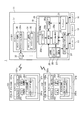
図1は、本実施形態に係るPOS(Point of Sales)システム1の概略構成ブロック図である。また、図2はPOSシステム1を構成する第1タブレット端末101、第2タブレット端末102(出力装置)、及び、ホスト装置11(サーバー装置)の機能的構成を示すブロック図である。
Hereinafter, embodiments of the present invention will be described with reference to the drawings.
FIG. 1 is a schematic block diagram of a POS (Point of Sales) system 1 according to the present embodiment. FIG. 2 is a block diagram showing a functional configuration of the first tablet terminal 101, the second tablet terminal 102 (output device), and the host device 11 (server device) constituting the POS system 1.

POSシステム1は、ショッピングセンターや、百貨店、コンビニエンスストア等の小売店、レストランや、喫茶店等の飲食店、その他の店舗、施設に適用されるシステムである。POSシステム1は、店舗における商品販売に関し、販売商品の登録、支払い金額算出、支払いに伴う会計処理、販売及び会計処理の結果を印刷するレシート発行、この会計処理に伴う情報の提供等を行う。また、POSシステム1は、店舗における商品の販売状況、商品の在庫の状況、売上の状況等を管理する機能を有する。
POSシステム1が使用される店舗には、会計処理を行う複数のレジカウンターが設けられている。そして、1つのレジカウンターには、少なくとも1台のホスト装置11が設けられ、さらに、複数の第2タブレット端末102を設置可能である。第1タブレット端末101、及び、1または複数の第2タブレット端末102は、ホスト装置11に接続される。
The POS system 1 is a system applied to a shopping center, a retail store such as a department store and a convenience store, a restaurant, a restaurant such as a coffee shop, and other stores and facilities. The POS system 1 performs registration of sales merchandise, calculation of a payment amount, accounting processing associated with payment, issuance of a receipt for printing the results of sales and accounting processing, provision of information associated with the accounting processing, and the like. The POS system 1 also has a function of managing the sales status of products in stores, the status of product inventory, the status of sales, and the like.
A store where the POS system 1 is used is provided with a plurality of cashier counters that perform accounting processing. One cash register counter is provided with at least one host device 11 and a plurality of second tablet terminals 102 can be installed. The first tablet terminal 101 and one or more second tablet terminals 102 are connected to the host device 11.

第1タブレット端末101、及び、第2タブレット端末102は、タブレット型(板状)のコンピューターであり、本実施形態では、前面に形成された表示領域にタッチパネルが設けられ、タッチ操作によって各種入力が可能なタイプの端末である(図5参照)。
第1タブレット端末101は、レジカウンターにおいて、会計を担当するレジ担当者(オペレーター)が使用する端末であり、後述するように、レジカウンターにおける会計に際し、レジ担当者にユーザーインターフェイスを提供する。
第2タブレット端末102は、レジカウンターにおいて、会計に関する情報、例えば、会計に係る合計金額等を、顧客に対して表示する。すなわち、第2タブレット端末102は、いわゆるカスタマーディスプレイとしての機能を果たす装置である。一般的なPOSシステムのカスタマーディスプレイとしては、数十×数百ドットのドットマトリクス式の表示パネルを備えた装置が挙げられる。これに対し、本実施形態に係るPOSシステム1は、汎用のタブレット端末をカスタマーディスプレイとして使用可能とし、従来のカスタマーディスプレイと比較して、高精細でダイナミックな画像を表示可能である。第2タブレット端末102は、レジカウンターにおいて、顧客が視認できる位置に配置される。また、一部の第2タブレット端末102を、レジカウンターから離れた場所に設置することも勿論可能である。
The first tablet terminal 101 and the second tablet terminal 102 are tablet-type (plate-like) computers. In this embodiment, a touch panel is provided in a display area formed on the front surface, and various inputs are performed by touch operations. This is a possible type of terminal (see FIG. 5).
The first tablet terminal 101 is a terminal used by a cashier in charge of accounting at the cashier counter. As described later, the first tablet terminal 101 provides a user interface to the cashier in charge at the cashier at the cashier counter.
The second tablet terminal 102 displays information related to the accounting, for example, the total amount related to the accounting, to the customer at the cashier counter. That is, the second tablet terminal 102 is a device that functions as a so-called customer display. As a customer display of a general POS system, there is an apparatus provided with a dot matrix type display panel of several tens of several hundred dots. On the other hand, the POS system 1 according to the present embodiment can use a general-purpose tablet terminal as a customer display, and can display a high-definition and dynamic image as compared with a conventional customer display. The 2nd tablet terminal 102 is arrange | positioned in the position which a customer can visually recognize in a cash register counter. Of course, it is possible to install some of the second tablet terminals 102 at locations away from the cashier counter.

ホスト装置11は、POSサーバー17及びデバイスサーバー18を備えた装置である。POSサーバー17は、POSシステム1を管理するサーバー装置として、第1タブレット端末101に対するデータの提供等を行う。
デバイスサーバー18には、入力デバイス(入力装置)としてバーコードスキャナー12及びカードリーダー13が接続されている。バーコードスキャナー12は、商品または商品の包装に付されたバーコードを読み取って、読取結果をデバイスサーバー18に出力する。バーコードスキャナー12は、Bluetooth(登録商標)の規格に準拠した近距離無線通信によってデバイスサーバー18と接続されてもよいし、USBインターフェイス等の有線通信インターフェイスにより接続されてもよい。カードリーダー13は、クレジットカードや顧客の会員カード等を読み取って、読取結果をデバイスサーバー18に出力する。カードリーダー13は、磁気カードに記録された磁気情報を読み取るものであってもよいし、ICカードに対する情報の読み書きを行うものであってもよい。カードリーダー13は、USB等の規格に準拠した有線通信インターフェイスによりデバイスサーバー18に接続される。
The host device 11 is a device including a POS server 17 and a device server 18. The POS server 17 is a server device that manages the POS system 1 and provides data to the first tablet terminal 101.
A barcode scanner 12 and a card reader 13 are connected to the device server 18 as input devices (input devices). The barcode scanner 12 reads the barcode attached to the product or the product packaging, and outputs the read result to the device server 18. The barcode scanner 12 may be connected to the device server 18 by short-range wireless communication based on the Bluetooth (registered trademark) standard, or may be connected by a wired communication interface such as a USB interface. The card reader 13 reads a credit card, a customer membership card, and the like, and outputs the read result to the device server 18. The card reader 13 may read magnetic information recorded on the magnetic card or read / write information from / to the IC card. The card reader 13 is connected to the device server 18 by a wired communication interface compliant with a standard such as USB.

デバイスサーバー18は、バーコードスキャナー12及びカードリーダー13から入力されるデータを第1タブレット端末101に送信する。また、デバイスサーバー18には、紙幣や、貨幣、金券等を収容するキャッシュドロワー14及びプリンターユニット21が接続されている。キャッシュドロワー14は、所定のシリアル通信の規格に準拠した有線通信方式によりデバイスサーバー18に接続される。デバイスサーバー18は、第1タブレット端末101から入力されるデータに基づき、キャッシュドロワー14を駆動して開かせる。また、デバイスサーバー18は、ホスト装置11の筐体に内蔵されるプリンターユニット21を制御して、レシートを印刷させる。さらに、デバイスサーバー18は、複数の第2タブレット端末102に対して表示データを送信する送信装置として機能する。   The device server 18 transmits data input from the barcode scanner 12 and the card reader 13 to the first tablet terminal 101. The device server 18 is connected to a cash drawer 14 and a printer unit 21 that store bills, money, cash vouchers, and the like. The cash drawer 14 is connected to the device server 18 by a wired communication method compliant with a predetermined serial communication standard. The device server 18 drives the cash drawer 14 to open based on data input from the first tablet terminal 101. Further, the device server 18 controls the printer unit 21 built in the housing of the host device 11 to print a receipt. Furthermore, the device server 18 functions as a transmission device that transmits display data to the plurality of second tablet terminals 102.

ホスト装置11が備えるPOSサーバー17及びデバイスサーバー18は、それぞれ別のハードウェアにより実現されてもよい。また、ホスト装置11の制御基板に実装されたコンピューターが、POSサーバー17に対応するプログラム、及びデバイスサーバー18に対応するプログラムをそれぞれ実行し、POSサーバー17及びデバイスサーバー18の機能を実現してもよい。また、プリンターユニット21は、ホスト装置11と同一の筐体に設けられているが、この筐体内で、プリンターユニット21の制御基板と、POSサーバー17及びデバイスサーバー18として動作する制御基板とを、別体として設けてもよい。   The POS server 17 and the device server 18 included in the host device 11 may be realized by different hardware. In addition, even if the computer mounted on the control board of the host device 11 executes the program corresponding to the POS server 17 and the program corresponding to the device server 18, respectively, the functions of the POS server 17 and the device server 18 are realized. Good. The printer unit 21 is provided in the same housing as the host device 11, and the control board of the printer unit 21 and the control boards that operate as the POS server 17 and the device server 18 are provided in the housing. It may be provided as a separate body.

図2に示すように、ホスト装置11は、第1タブレット端末101及び第2タブレット端末102と通信を行うサーバーインターフェイス(I/F)32を備え、POSサーバー17とデバイスサーバー18とが接続されている。サーバーインターフェイス32は、所定のネットワークカード等の通信インターフェイスを備え、POSサーバー17が備えるPOSサーバー制御部30、及び、デバイスサーバー18が備えるデバイス制御部20の制御により動作する。サーバーインターフェイス32は、POSサーバー制御部30及びデバイス制御部20の制御に従い、第1タブレット端末101、及び、第2タブレット端末102との間で所定の無線通信プロトコルを実行し、各種データを送受信する。これにより、POSサーバー17及びデバイスサーバー18は、サーバーインターフェイス32を介して第1タブレット端末101及び第2タブレット端末102と通信を行う。   As shown in FIG. 2, the host device 11 includes a server interface (I / F) 32 that communicates with the first tablet terminal 101 and the second tablet terminal 102, and the POS server 17 and the device server 18 are connected to each other. Yes. The server interface 32 includes a communication interface such as a predetermined network card, and operates under the control of the POS server control unit 30 included in the POS server 17 and the device control unit 20 included in the device server 18. The server interface 32 executes a predetermined wireless communication protocol with the first tablet terminal 101 and the second tablet terminal 102 according to the control of the POS server control unit 30 and the device control unit 20, and transmits and receives various data. . Thereby, the POS server 17 and the device server 18 communicate with the first tablet terminal 101 and the second tablet terminal 102 via the server interface 32.

デバイスサーバー18は、デバイス制御部20と、プリンターユニット21(印刷部)と、無線デバイス通信部22と、有線デバイス通信部24と、記憶部25と、を備えている。
デバイス制御部20は、デバイスサーバー18の各部を制御するものであり、図示しないCPUや、ROM、RAM、その他の周辺回路等を備えている。デバイス制御部20は、プリンターユニット制御部20a、通信部20b、デバイス通信制御部20c、及びデータ配信部20dの各部を備える。これらの各機能ブロックは、例えば、デバイスサーバー18のCPUがプログラムを実行することにより実現される。プリンターユニット制御部20aは、プリンターユニット21の制御に係るプログラムを実行してプリンターユニット21を制御する。
The device server 18 includes a device control unit 20, a printer unit 21 (printing unit), a wireless device communication unit 22, a wired device communication unit 24, and a storage unit 25.
The device control unit 20 controls each unit of the device server 18, and includes a CPU, a ROM, a RAM, and other peripheral circuits (not shown). The device control unit 20 includes a printer unit control unit 20a, a communication unit 20b, a device communication control unit 20c, and a data distribution unit 20d. Each of these functional blocks is realized by the CPU of the device server 18 executing a program, for example. The printer unit control unit 20 a controls the printer unit 21 by executing a program related to the control of the printer unit 21.

プリンターユニット21は、プリンターユニット制御部20aの制御の下、ロール紙を搬送する搬送機構、サーマルヘッドによってロール紙に文字や画像を印刷する印刷機構、ロール紙を切断するカッター機構等を備えている。プリンターユニット21は、ロール紙にレシートに係る画像を印刷した後、所定の位置でロール紙を切断することにより、レシートを発行する。また、プリンターユニット21には、キャッシュドロワー14がデイジーチェーン接続されている。プリンターユニット制御部20aは、プリンターユニット21を介して、所定のシリアル通信規格に準拠したプロトコルでキャッシュドロワー14と通信可能に接続されている。プリンターユニット21は、プリンターユニット制御部20aの制御の下、適宜、キャッシュドロワー14を制御して、例えば、キャッシュドロワー14に設けられた引き出しを開かせる。   The printer unit 21 includes a transport mechanism that transports roll paper under the control of the printer unit control unit 20a, a printing mechanism that prints characters and images on the roll paper using a thermal head, a cutter mechanism that cuts the roll paper, and the like. . The printer unit 21 prints an image relating to the receipt on the roll paper, and then issues the receipt by cutting the roll paper at a predetermined position. Further, the cash drawer 14 is daisy chain connected to the printer unit 21. The printer unit control unit 20a is connected to the cash drawer 14 via the printer unit 21 by a protocol compliant with a predetermined serial communication standard. The printer unit 21 appropriately controls the cash drawer 14 under the control of the printer unit control unit 20a to open, for example, a drawer provided in the cash drawer 14.

通信部20bは、通信の制御に係るプログラムを実行して第1タブレット端末101、及び、第2タブレット端末102との間で行われる通信を制御する。
通信部20bは、端末インターフェイス271を介して第1端末制御部261と接続されて、第1端末制御部261から送信されたデータを受信する。通信部20bは、受信したデータを、後述する記憶部25に設けられた配信バッファー26に記憶させる機能を有する。
また、通信部20bは、端末インターフェイス272を介して、第2端末制御部262と接続される。通信部20bは、データ配信部20dと協働して、第2端末制御部262に対して、第1タブレット端末101から受信したデータを送信する機能を有する。データ配信部20dは、後述する記憶部25に設けられた配信バッファー26内のデータを、第2タブレット端末102に送信する。
デバイス通信制御部20cは、デバイスの制御に係るプログラムを実行して、各デバイスと通信し、各デバイスを制御する。
上述したプリンターユニット21の制御に係るプログラムや、通信の制御に係るプログラム、デバイスの制御に係るプログラムは、例えば、ホスト装置11のメーカーが提供する専用のAPI(Application Program Interface)を利用して生成され、これをデバイス制御部20が実行する。
The communication unit 20b executes a program related to communication control to control communication performed between the first tablet terminal 101 and the second tablet terminal 102.
The communication unit 20b is connected to the first terminal control unit 261 via the terminal interface 271 and receives data transmitted from the first terminal control unit 261. The communication unit 20b has a function of storing received data in a distribution buffer 26 provided in the storage unit 25 described later.
Further, the communication unit 20b is connected to the second terminal control unit 262 via the terminal interface 272. The communication unit 20b has a function of transmitting data received from the first tablet terminal 101 to the second terminal control unit 262 in cooperation with the data distribution unit 20d. The data distribution unit 20 d transmits data in the distribution buffer 26 provided in the storage unit 25 described later to the second tablet terminal 102.
The device communication control unit 20c executes a program related to device control, communicates with each device, and controls each device.
The program related to the control of the printer unit 21, the program related to communication control, and the program related to device control are generated using, for example, a dedicated API (Application Program Interface) provided by the manufacturer of the host device 11. The device control unit 20 executes this.

無線デバイス通信部22は、バーコードスキャナー12との間でBluetoothの規格に準拠した近距離無線通信を行うものであり、リンクマネージャーや、リンクコントローラー、高周波回路、アンテナ等を含んで構成されている。デバイス通信制御部20cは、Bluetoothハードウェアを制御する、いわゆるBluetooth Driver Stackを読み出して実行する。これにより、デバイス通信制御部20cは無線デバイス通信部22を制御して、バーコードスキャナー12との間でBluetoothの規格に準拠して近距離無線通信を行う。
有線デバイス通信部24は、物理ポートに接続されたネットワークインターフェイスカード等を備え、カードリーダー13との間でUSB等の所定の通信プロトコルを実行して有線通信を行う。デバイス通信制御部20cは、有線デバイス通信部24を制御して、カードリーダー13との間で各種データまたは信号を送受信する。
記憶部25は、磁気的、光学的記憶媒体または半導体記憶素子で構成される不揮発性の記憶装置により構成される。記憶部25は、各種のプログラムやデータを、上記CPUにより読み取り可能な態様で、書き換え可能に記憶する。記憶部25には、後述する複数の配信バッファー26(記憶領域)が形成される。また、記憶部25には後述するバッファー対応情報27(対応情報)が記憶されている。
The wireless device communication unit 22 performs short-range wireless communication based on the Bluetooth standard with the barcode scanner 12, and includes a link manager, a link controller, a high-frequency circuit, an antenna, and the like. . The device communication control unit 20c reads and executes a so-called Bluetooth Driver Stack that controls the Bluetooth hardware. Accordingly, the device communication control unit 20c controls the wireless device communication unit 22 to perform short-range wireless communication with the barcode scanner 12 in accordance with the Bluetooth standard.
The wired device communication unit 24 includes a network interface card connected to the physical port, and performs a wired communication with the card reader 13 by executing a predetermined communication protocol such as USB. The device communication control unit 20 c controls the wired device communication unit 24 to transmit / receive various data or signals to / from the card reader 13.
The storage unit 25 is configured by a non-volatile storage device including a magnetic or optical storage medium or a semiconductor storage element. The storage unit 25 stores various programs and data in a readable manner by the CPU. A plurality of distribution buffers 26 (storage areas) described later are formed in the storage unit 25. The storage unit 25 stores buffer correspondence information 27 (correspondence information) described later.

POSサーバー17は、商品に関する情報を格納したデータベース、売り上げを管理するデータベース、在庫を管理するデータベース等を記憶するPOSサーバー記憶部31を備え、これらデータベースを利用して、POSシステム1を管理する。
POSサーバー17は、POSサーバー制御部30と、POSサーバー記憶部31とを備え、サーバーインターフェイス32に接続される。
The POS server 17 includes a POS server storage unit 31 that stores a database that stores information about products, a database that manages sales, a database that manages inventory, and the like, and manages the POS system 1 using these databases.
The POS server 17 includes a POS server control unit 30 and a POS server storage unit 31 and is connected to a server interface 32.

POSサーバー制御部30は、POSサーバー17の各部を制御するものであり、図示しないCPUや、ROM、RAM、その他の周辺回路等を備えている。上述のように、これらのCPU,ROM、RAM、及びその他の周辺回路はデバイス制御部20と共通であってもよい。
POSサーバー記憶部31は、磁気的、光学的記憶媒体または半導体記憶素子で構成される不揮発性の記憶装置により構成される。POSサーバー記憶部31は、各種のプログラムやデータを、上記CPUにより読み取り可能な態様で、書き換え可能に記憶する。POSサーバー記憶部31は、記憶部25と共通の記憶装置により構成されてもよい。
POSサーバー記憶部31には、アプリケーション35がロード可能に記憶されている。そして、アプリケーション実行部30aは、アプリケーション35を読み出して実行することにより、単独で、又は、第1ブラウザー実行部261aと協働して、各種処理を実行する。アプリケーション実行部30aは、第1タブレット端末101、又は、第2タブレット端末102から要求されたウェブページのデータを生成し、或いはPOSサーバー記憶部31から読み出して、要求元の端末に送信する。各端末は、受信したウェブページのデータに基づいて、後述する画面を表示する。
The POS server control unit 30 controls each unit of the POS server 17 and includes a CPU, ROM, RAM, and other peripheral circuits (not shown). As described above, these CPU, ROM, RAM, and other peripheral circuits may be common to the device control unit 20.
The POS server storage unit 31 is configured by a nonvolatile storage device including a magnetic or optical storage medium or a semiconductor storage element. The POS server storage unit 31 stores various programs and data in a readable manner by the CPU. The POS server storage unit 31 may be configured by a storage device common to the storage unit 25.
The POS server storage unit 31 stores an application 35 so that it can be loaded. Then, the application execution unit 30a executes various processes by reading and executing the application 35 alone or in cooperation with the first browser execution unit 261a. The application execution unit 30a generates web page data requested from the first tablet terminal 101 or the second tablet terminal 102, or reads the data from the POS server storage unit 31 and transmits it to the requesting terminal. Each terminal displays a screen to be described later based on the received web page data.

第1タブレット端末101は、第1端末制御部261、端末インターフェイス(I/F)271、表示制御部281、入力検出部291、及び、タッチパネル101aを備えている。
タッチパネル101aは、第1タブレット端末101の前面に配置された表示パネル101cと、表示パネル101cに重ねて配置されたタッチセンサー101bとで構成されている。表示パネル101cは、液晶表示パネル、有機ELパネル、電子ペーパー等のディスプレイであり、表示制御部281によって駆動される。タッチセンサー101bは、表示パネル101cに重ねて配置された静電容量式もしくは感圧式のセンサーであり、ユーザーの手指やペン型操作デバイスによる接触操作を検出して、操作を検出した位置を示す信号を入力検出部291に出力する。
表示制御部281は、後述する第1ブラウザー実行部261aから入力される表示データに基づいて、表示パネル101cを駆動し、表示パネル101cに文字や画像等を含む画面を表示する。
入力検出部291は、タッチセンサー101bが出力する信号に基づいて、タッチパネル101aに対する接触操作を検出する。この操作を検出した場合、入力検出部291は、操作位置を、表示パネル101cの表示位置に対応する座標により示す座標データを生成し、第1ブラウザー実行部261aに出力する。
The first tablet terminal 101 includes a first terminal control unit 261, a terminal interface (I / F) 271, a display control unit 281, an input detection unit 291, and a touch panel 101a.
The touch panel 101a includes a display panel 101c disposed on the front surface of the first tablet terminal 101 and a touch sensor 101b disposed on the display panel 101c. The display panel 101 c is a display such as a liquid crystal display panel, an organic EL panel, or electronic paper, and is driven by the display control unit 281. The touch sensor 101b is a capacitance-type or pressure-sensitive sensor that is placed on the display panel 101c, detects a contact operation by a user's finger or a pen-type operation device, and indicates a position where the operation is detected. Is output to the input detection unit 291.
The display control unit 281 drives the display panel 101c based on display data input from a first browser execution unit 261a described later, and displays a screen including characters, images, and the like on the display panel 101c.
The input detection unit 291 detects a touch operation on the touch panel 101a based on a signal output from the touch sensor 101b. When this operation is detected, the input detection unit 291 generates coordinate data indicating the operation position by coordinates corresponding to the display position of the display panel 101c, and outputs the coordinate data to the first browser execution unit 261a.

第1端末制御部261は、第1タブレット端末101の各部を制御するものであり、CPUや、ROM、RAM、その他の周辺回路等を備えている。第1端末制御部261は、ブラウザープログラムを実行することにより、ブラウザーの機能を実現する第1ブラウザー実行部261aを備えている。
第1ブラウザー実行部261aは、ブラウザーの機能により、HTML等のマークアップ言語やスクリプト言語で記述されたウェブページを、POSサーバー17からダウンロードする。ダウンロードされたウェブページのデータは、例えば図示しないRAMに記憶される。第1ブラウザー実行部261aは、ブラウザーの機能により、ダウンロードされたウェブページのデータを読み込み、このウェブページを表示させる表示データを生成して、表示制御部281に出力する。また、第1ブラウザー実行部261aは、ウェブページに実装されたスクリプトの機能により、単独で、又は、アプリケーション実行部30aと協働して、各種処理を実行する。
従って、第1タブレット端末101は、第1ブラウザー実行部261aの動作、または、第1ブラウザー実行部261aとPOSサーバー17のアプリケーション実行部30aとの協働により、POS端末装置として機能する。
The first terminal control unit 261 controls each unit of the first tablet terminal 101, and includes a CPU, a ROM, a RAM, other peripheral circuits, and the like. The first terminal control unit 261 includes a first browser execution unit 261a that realizes a browser function by executing a browser program.
The first browser execution unit 261a downloads a web page described in a markup language such as HTML or a script language from the POS server 17 by a browser function. The downloaded web page data is stored in a RAM (not shown), for example. The first browser execution unit 261a reads the downloaded web page data by using the browser function, generates display data for displaying the web page, and outputs the display data to the display control unit 281. In addition, the first browser execution unit 261a executes various processes independently or in cooperation with the application execution unit 30a by the function of the script mounted on the web page.
Therefore, the first tablet terminal 101 functions as a POS terminal device by the operation of the first browser execution unit 261a or the cooperation of the first browser execution unit 261a and the application execution unit 30a of the POS server 17.

第1ブラウザー実行部261aは、タッチセンサー101bへのタッチ操作に対応して入力検出部291から入力される座標データと表示制御部281に出力した表示データに基づき、入力された内容を特定する。第1ブラウザー実行部261aは、適宜、特定した入力内容に基づいて、スクリプトの機能によって適切な処理を実行し、また、特定した入力内容を示すデータをPOSサーバー17へ送信する。アプリケーション実行部30aは、入力されたデータに基づいて各種処理を実行する。また、第1ブラウザー実行部261aは、アプリケーション実行部30aがアプリケーションプログラムを実行した実行結果のデータをPOSサーバー17から受信して、受信したデータを反映した表示データを生成して表示制御部281に出力する。
端末インターフェイス271(I/F)は、第1端末制御部261の制御の下、デバイスサーバー18、及び、POSサーバー17と、所定の無線通信プロトコルを実行して通信を行う。この端末インターフェイス271と、第1端末制御部261とが協働して、ブラウザーからのデータを送信する「送信部」として機能する。
The first browser execution unit 261a specifies the input content based on the coordinate data input from the input detection unit 291 and the display data output to the display control unit 281 in response to a touch operation on the touch sensor 101b. The first browser execution unit 261a appropriately executes appropriate processing by the function of the script based on the specified input content, and transmits data indicating the specified input content to the POS server 17. The application execution unit 30a executes various processes based on the input data. In addition, the first browser execution unit 261a receives data of an execution result obtained by executing the application program by the application execution unit 30a from the POS server 17, generates display data reflecting the received data, and sends the display data to the display control unit 281. Output.
The terminal interface 271 (I / F) performs communication with the device server 18 and the POS server 17 by executing a predetermined wireless communication protocol under the control of the first terminal control unit 261. The terminal interface 271 and the first terminal control unit 261 cooperate to function as a “transmission unit” that transmits data from the browser.

第2タブレット端末102は、第1タブレット端末101と同様、第2端末制御部262(第2制御部)、端末インターフェイス(I/F)272、表示制御部282、入力検出部292、及び、タッチパネル102aを備えている。
タッチパネル102aは、第2タブレット端末102の前面に配置された表示パネル102c(表示部)と、表示パネル102cに重ねて配置されたタッチセンサー102bとで構成されている。表示パネル102cは、液晶表示パネル、有機ELパネル、電子ペーパー等のディスプレイであり、表示制御部282によって駆動される。タッチセンサー102bは、表示パネル102cに重ねて配置された静電容量式もしくは感圧式のセンサーであり、ユーザーの手指やペン型操作デバイスによる接触操作を検出して、操作を検出した位置を示す信号を入力検出部292に出力する。
表示制御部282は、後述する第2ブラウザー実行部262aから入力される表示データに基づいて、表示パネル102cを駆動し、表示パネル102cに文字や画像等を含む画面を表示する。
入力検出部292は、タッチセンサー102bが出力する信号に基づいて、タッチパネル102aに対する接触操作を検出する。この操作を検出した場合、入力検出部292は、操作位置を、表示パネル102cの表示位置に対応する座標により示す座標データを生成し、第2ブラウザー実行部262aに出力する。
Similar to the first tablet terminal 101, the second tablet terminal 102 includes a second terminal control unit 262 (second control unit), a terminal interface (I / F) 272, a display control unit 282, an input detection unit 292, and a touch panel. 102a.
The touch panel 102a includes a display panel 102c (display unit) disposed on the front surface of the second tablet terminal 102 and a touch sensor 102b disposed on the display panel 102c. The display panel 102 c is a display such as a liquid crystal display panel, an organic EL panel, or electronic paper, and is driven by the display control unit 282. The touch sensor 102b is a capacitance-type or pressure-sensitive sensor that is placed on the display panel 102c, and detects a contact operation with a user's finger or a pen-type operation device, and indicates a position where the operation is detected. Is output to the input detection unit 292.
The display control unit 282 drives the display panel 102c based on display data input from a second browser execution unit 262a described later, and displays a screen including characters, images, and the like on the display panel 102c.
The input detection unit 292 detects a touch operation on the touch panel 102a based on a signal output from the touch sensor 102b. When this operation is detected, the input detection unit 292 generates coordinate data indicating the operation position by coordinates corresponding to the display position of the display panel 102c, and outputs the coordinate data to the second browser execution unit 262a.

第2端末制御部262は、第2タブレット端末102の各部を制御するものであり、CPUや、ROM、RAM、その他の周辺回路等を備えている。第2端末制御部262は、ブラウザープログラムを実行することにより、ブラウザーの機能を実現する第2ブラウザー実行部262aを備えている。   The second terminal control unit 262 controls each unit of the second tablet terminal 102 and includes a CPU, a ROM, a RAM, other peripheral circuits, and the like. The second terminal control unit 262 includes a second browser execution unit 262a that realizes a browser function by executing a browser program.

第2ブラウザー実行部262aは、ブラウザーの機能により、HTML等のマークアップ言語やスクリプト言語で記述されたウェブページを、デバイスサーバー18からダウンロードする。ダウンロードされたウェブページのデータは、例えば図示しないRAMに記憶される。第2ブラウザー実行部262aは、ブラウザーの機能により、ダウンロードされたウェブページのデータを読み込み、このウェブページを表示させる表示データを生成して、表示制御部282に出力する。   The second browser execution unit 262a downloads a web page described in a markup language such as HTML or a script language from the device server 18 by the browser function. The downloaded web page data is stored in a RAM (not shown), for example. The second browser execution unit 262a reads the downloaded web page data by the browser function, generates display data for displaying the web page, and outputs the display data to the display control unit 282.

第2ブラウザー実行部262aは、ROM(図示略)に表示するウェブページを記憶していてもよい。このウェブページのデータは、後述する配置情報112(図3)である。図4(B)及び図5(B)を参照して後述するように、表示パネル102cに表示される画面には、POSシステム1が実行する会計に関する情報を表示する各種表示エリアが配置されている。第2ブラウザー実行部262aが有する配置情報112には、表示エリアの位置やサイズ、表示画面の枠等を設定するデータが含まれる。さらに、配置情報112には、表示エリアに表示されるデータを取得するスクリプト等が含まれる。第2ブラウザー実行部262aが表示する画面には会計処理の内容に対応したデータが含まれるが、このデータは会計処理の実行中にデバイスサーバー18から送信され、会計処理の内容により変化する。配置情報112には、デバイスサーバー18から送信されるデータを配置する情報が含まれている。第2ブラウザー実行部262aは、会計処理の実行中にデバイスサーバー18から送信されるデータを、配置情報112に従って表示エリアに配置して表示データを生成し、表示制御部282に出力して、表示パネル102cに表示させる。また、第2ブラウザー実行部262aは、デバイスサーバー18から新たにデータを受信する毎に表示エリアに新たなデータを配置して、表示データを更新する。これにより、第2ブラウザー実行部262aは、動的にデータを表示できる。   The second browser execution unit 262a may store a web page to be displayed on a ROM (not shown). The data of this web page is arrangement information 112 (FIG. 3) described later. As will be described later with reference to FIG. 4B and FIG. 5B, various display areas for displaying information related to the accounting executed by the POS system 1 are arranged on the screen displayed on the display panel 102c. Yes. The arrangement information 112 included in the second browser execution unit 262a includes data for setting the position and size of the display area, the frame of the display screen, and the like. Furthermore, the arrangement information 112 includes a script for acquiring data displayed in the display area. The screen displayed by the second browser execution unit 262a includes data corresponding to the contents of the accounting process. This data is transmitted from the device server 18 during the execution of the accounting process, and changes depending on the contents of the accounting process. The arrangement information 112 includes information for arranging data transmitted from the device server 18. The second browser execution unit 262a generates display data by arranging data transmitted from the device server 18 during execution of the accounting process in the display area according to the arrangement information 112, and outputs the display data to the display control unit 282 for display. It is displayed on the panel 102c. The second browser execution unit 262a arranges new data in the display area each time new data is received from the device server 18, and updates the display data. Thereby, the second browser execution unit 262a can dynamically display data.

本実施形態の第2タブレット端末102では、端末インターフェイス272と、第2端末制御部262とが協働して、通信部20bから送信されたデータを受信する「受信部」として機能する。また、タッチパネル102aは、第2端末制御部262(出力制御部)で制御されたブラウザーを表示する「表示部」として機能する。
以下の説明では、第1タブレット端末101、及び、第2タブレット端末102を総称して、適宜、「端末」と表現するものとする。
In the second tablet terminal 102 of the present embodiment, the terminal interface 272 and the second terminal control unit 262 cooperate to function as a “reception unit” that receives data transmitted from the communication unit 20b. The touch panel 102a functions as a “display unit” that displays a browser controlled by the second terminal control unit 262 (output control unit).
In the following description, the first tablet terminal 101 and the second tablet terminal 102 are collectively referred to as “terminal” as appropriate.

図3は、第1タブレット端末101と、デバイスサーバー18と、第2タブレット端末102との間でデータを送受信する動作の説明図である。図3には、デバイス制御部20が備える通信部20b、データ配信部20d、第1ブラウザー実行部261a、及び、第2ブラウザー実行部262aの関係を説明に適した態様で模式的に示す。   FIG. 3 is an explanatory diagram of an operation of transmitting and receiving data among the first tablet terminal 101, the device server 18, and the second tablet terminal 102. FIG. 3 schematically illustrates the relationship among the communication unit 20b, the data distribution unit 20d, the first browser execution unit 261a, and the second browser execution unit 262a included in the device control unit 20 in a mode suitable for explanation.

本実施形態では、第1ブラウザー実行部261aから、第2ブラウザー実行部262aに対して、通信部20bを介して、データを送信可能である。図3には、第1ブラウザー実行部261aから、第2ブラウザー実行部262aへのデータの送信を実現する各機能ブロックを示している。
POSシステム1が起動すると、第1ブラウザー実行部261aと通信部20bとの間で、データを送受信する通信経路である第1経路K1が確立される。すなわち、第1ブラウザー実行部261aと通信部20bとは、ウェブソケット(WebSocket)の規格に準拠してコネクションを張る。第1経路K1は、第1ブラウザー実行部261aと通信部20bとが、ウェブソケットの規格に準拠してデータの送受信を行うソフトウェアのインターフェイスを形成することにより、実現される。第1経路K1は、例えば、Socket.ioライブラリーを利用した、ウェブソケットの規格に準拠した通信経路であるが、Comet等の他の規格を利用するものであってもよい。
In the present embodiment, data can be transmitted from the first browser execution unit 261a to the second browser execution unit 262a via the communication unit 20b. FIG. 3 shows functional blocks that realize transmission of data from the first browser execution unit 261a to the second browser execution unit 262a.
When the POS system 1 is activated, a first path K1, which is a communication path for transmitting and receiving data, is established between the first browser execution unit 261a and the communication unit 20b. That is, the first browser execution unit 261a and the communication unit 20b establish a connection in accordance with the web socket standard. The first path K1 is realized by the first browser execution unit 261a and the communication unit 20b forming a software interface that transmits and receives data according to the web socket standard. The first route K1 is, for example, Socket. Although the communication path conforms to the web socket standard using the io library, another standard such as Comet may be used.

POSシステム1が起動する際には、第2ブラウザー実行部262aと通信部20bとの間で、データを送受信する通信経路である第2経路K2が確立される。第2経路K2は、第1経路K1と同様、ウェブソケットの規格に準拠して張られたコネクションに基づく通信経路である。POSシステム1では複数の第2タブレット端末102をデバイスサーバー18に接続して使用可能である。このため、POSシステム1の起動時、または起動後の所定のタイミングで、POSシステム1で使用する第2タブレット端末102をデバイスサーバー18に接続させる。このとき、各々の第2タブレット端末102は、デバイス制御部20との間で第2経路K2を形成する。第2経路K2はウェブソケット規格に準拠したプッシュ型送信を行うことが可能な通信経路である。このため、第2経路K2を形成した後は、デバイス制御部20から第2ブラウザー実行部262aに対し、データをプッシュ送信できる。すなわち、第2ブラウザー実行部262aがデバイス制御部20に対してリクエストを送信し、リクエストの返信としてデバイス制御部20がデータを送信する手順を必要としない。第2ブラウザー実行部262aに送信すべきデータがある場合に、デバイス制御部20がデータを第2ブラウザー実行部262aに送信できる。   When the POS system 1 is activated, a second path K2, which is a communication path for transmitting and receiving data, is established between the second browser execution unit 262a and the communication unit 20b. The second path K2 is a communication path based on a connection established in accordance with the web socket standard, like the first path K1. In the POS system 1, a plurality of second tablet terminals 102 can be connected to the device server 18 and used. Therefore, the second tablet terminal 102 used in the POS system 1 is connected to the device server 18 when the POS system 1 is activated or at a predetermined timing after activation. At this time, each second tablet terminal 102 forms a second path K <b> 2 with the device control unit 20. The second path K2 is a communication path capable of performing push-type transmission conforming to the web socket standard. For this reason, after the second path K2 is formed, data can be push-transmitted from the device control unit 20 to the second browser execution unit 262a. That is, the second browser execution unit 262a transmits a request to the device control unit 20, and the device control unit 20 does not need to transmit data as a response to the request. When there is data to be transmitted to the second browser execution unit 262a, the device control unit 20 can transmit the data to the second browser execution unit 262a.

記憶部25には、複数の配信バッファー26が生成される。配信バッファー26は、記憶部25のデータ記憶領域の一部を区切って設けられた記憶領域である。配信バッファー26は、データ配信部20dの制御により新たに生成することも消去することも可能である。記憶部25に設けられる各配信バッファー26には固有の識別情報がデータ配信部20dにより付与される。図3の例では、#1〜#4の番号が、識別情報として付与されているが、この識別情報は各配信バッファー26を識別できればよく、英数字を含む符号(名称)等であってもよい。   A plurality of distribution buffers 26 are generated in the storage unit 25. The distribution buffer 26 is a storage area provided by dividing a part of the data storage area of the storage unit 25. The distribution buffer 26 can be newly generated or deleted under the control of the data distribution unit 20d. Each distribution buffer 26 provided in the storage unit 25 is given unique identification information by the data distribution unit 20d. In the example of FIG. 3, the numbers # 1 to # 4 are given as identification information. However, this identification information only needs to identify each distribution buffer 26, and may be a code (name) including alphanumeric characters. Good.

配信バッファー26は、デバイス制御部20が第2経路K2を形成した第2タブレット端末102に対応づけられている。配信バッファー26に対応づける第2タブレット端末102は、第2経路K2を形成した第2タブレット端末102のうち任意のものが選択可能である。1つの第2タブレット端末102に複数の配信バッファー26を対応づけることも、1つの配信バッファー26に複数の第2タブレット端末102を対応づけることも可能である。   The distribution buffer 26 is associated with the second tablet terminal 102 on which the device control unit 20 has formed the second route K2. As the second tablet terminal 102 associated with the distribution buffer 26, any one of the second tablet terminals 102 that have formed the second route K2 can be selected. A plurality of distribution buffers 26 can be associated with one second tablet terminal 102, and a plurality of second tablet terminals 102 can be associated with one distribution buffer 26.

各々の配信バッファー26と、第2タブレット端末102との対応は、バッファー対応情報27により定義される。バッファー対応情報27は、デバイス制御部20と第2タブレット端末102とが第2経路K2を形成すると、データ配信部20dによって生成され、更新される。すなわち、1つの第2タブレット端末102が第2経路K2を形成すると、この第2タブレット端末102を対応づける配信バッファー26が選択され、対応づけに関するバッファー対応情報27が、データ配信部20dにより生成または更新される。ここで、データ配信部20dは対応情報制御部として機能する。
バッファー対応情報27は、例えば、配信バッファー26を識別する識別情報と、第2タブレット端末102を識別する識別情報とを用いて、対応づけを記述したファイルである。第2タブレット端末102を識別する識別情報としては、第2経路K2に対して付与されたID、第2タブレット端末102の名称、第2タブレット端末102のIPアドレス等を用いることができる。
The correspondence between each distribution buffer 26 and the second tablet terminal 102 is defined by the buffer correspondence information 27. The buffer correspondence information 27 is generated and updated by the data distribution unit 20d when the device control unit 20 and the second tablet terminal 102 form the second path K2. That is, when one second tablet terminal 102 forms the second route K2, a distribution buffer 26 that associates the second tablet terminal 102 is selected, and buffer correspondence information 27 relating to the association is generated or generated by the data distribution unit 20d. Updated. Here, the data distribution unit 20d functions as a correspondence information control unit.
The buffer correspondence information 27 is, for example, a file in which association is described using identification information for identifying the distribution buffer 26 and identification information for identifying the second tablet terminal 102. As identification information for identifying the second tablet terminal 102, an ID assigned to the second route K2, the name of the second tablet terminal 102, the IP address of the second tablet terminal 102, and the like can be used.

デバイス制御部20が第2ブラウザー実行部262aにデータを送信する場合、第1ブラウザー実行部261aは、当該データを、第1経路K1を介して通信部20bに送信する。ここで、通信部20bは、第1経路K1を介して受信したデータを、記憶部25に設けられた配信バッファー26に記憶させる。ここで、通信部20bは、第1経路K1を介して送信されたデータに対応する配信バッファー26を選択して、記憶させる。例えば、第1ブラウザー実行部261aが、データとともに、このデータを記憶する配信バッファー26を指定する情報を送信した場合、通信部20bは、情報により指定された配信バッファー26に、受信したデータを記憶させてもよい。ここで、データを記憶する配信バッファー26を指定する情報が、第1ブラウザー実行部261aが送信するデータに付加され、或いは、当該データに含まれていてもよい。
また、通信部20bは、第1ブラウザー実行部261aから受信したデータの属性を判定し、属性に対して予め対応づけられた配信バッファー26にデータを記憶させてもよい。具体的には、#1の配信バッファー26が商品コードに対応し、#2の配信バッファー26が合計金額に対応し、#3の配信バッファー26が商品画像の画像データに対応づけられている場合を想定する。この場合、第1ブラウザー実行部261aが商品画像の画像データを送信すると、通信部20bは、受信した画像データを#3の配信バッファー26に記憶させる。通信部20bが判定する属性は、上記の例のように、商品販売に係る会計処理におけるデータの役割であってもよいし、画像データとテキストデータのようなデータ自体のフォーマットであってもよい。また、第1ブラウザー実行部261aがデバイスサーバー18に送信するデータに、そのデータの属性を示す情報(属性情報)が含まれていてもよい。
When the device control unit 20 transmits data to the second browser execution unit 262a, the first browser execution unit 261a transmits the data to the communication unit 20b via the first path K1. Here, the communication unit 20b stores the data received via the first path K1 in the distribution buffer 26 provided in the storage unit 25. Here, the communication unit 20b selects and stores the distribution buffer 26 corresponding to the data transmitted via the first path K1. For example, when the first browser execution unit 261a transmits information specifying the distribution buffer 26 storing the data together with the data, the communication unit 20b stores the received data in the distribution buffer 26 specified by the information. You may let them. Here, information specifying the distribution buffer 26 for storing the data may be added to the data transmitted by the first browser execution unit 261a or may be included in the data.
Further, the communication unit 20b may determine the attribute of the data received from the first browser execution unit 261a, and store the data in the distribution buffer 26 associated with the attribute in advance. Specifically, when the # 1 distribution buffer 26 corresponds to the product code, the # 2 distribution buffer 26 corresponds to the total amount, and the # 3 distribution buffer 26 corresponds to the image data of the product image Is assumed. In this case, when the first browser execution unit 261a transmits the image data of the product image, the communication unit 20b stores the received image data in the # 3 distribution buffer 26. The attribute determined by the communication unit 20b may be the role of data in accounting processing related to product sales, as in the above example, or the format of data itself such as image data and text data. . In addition, information (attribute information) indicating an attribute of the data may be included in the data transmitted to the device server 18 by the first browser execution unit 261a.

データ配信部20dは、通信部20bがいずれかの配信バッファー26にデータを記憶させたことを検出し、新たにデータが記憶された配信バッファー26を特定する。そして、特定した配信バッファー26に対応する第2タブレット端末102を、バッファー対応情報27に基づき選択する。そして、データ配信部20dは、選択した第2タブレット端末102に、新たに配信バッファー26に記憶されたデータを送信する。ここで、データ配信部20dは、プリンターユニット制御部20aの機能により第2経路K2を介して、データをプッシュ送信する。このため、第1ブラウザー実行部261aがデバイス制御部20に送信したデータは、対応する第2タブレット端末102に送信される。   The data distribution unit 20d detects that the communication unit 20b has stored data in any of the distribution buffers 26, and specifies the distribution buffer 26 in which the data is newly stored. Then, the second tablet terminal 102 corresponding to the specified distribution buffer 26 is selected based on the buffer correspondence information 27. Then, the data distribution unit 20 d transmits the data newly stored in the distribution buffer 26 to the selected second tablet terminal 102. Here, the data distribution unit 20d push-transmits the data via the second path K2 by the function of the printer unit control unit 20a. Therefore, the data transmitted from the first browser execution unit 261a to the device control unit 20 is transmitted to the corresponding second tablet terminal 102.

さらに、データ配信部20dは、配信バッファー26に記憶されたデータを第2タブレット端末102に送信する際に、データが記憶されていた配信バッファー26の識別情報を合わせて送信する。第2タブレット端末102は、データと、データが記憶されていた配信バッファー26の識別情報を受信する。
第2ブラウザー実行部262aは、第2経路K2を介して送信されたデータを受信すると、受信したデータを表示する表示データを生成して、表示制御部282(図1)に出力し、表示パネル102cに表示させる。詳細には、第2ブラウザー実行部262aは、配置情報112を参照し、配置情報112に定義された表示態様で表示パネル102cに表示させる。配置情報112には、表示パネル102cにおける表示エリアの位置、サイズに関する情報のほか、デバイス制御部20から受信したデータを表示する表示エリアを指定する情報が含まれる。この情報は、受信したデータが記憶されていた配信バッファー26の識別情報と、受信したデータを表示するエリアとを対応づける情報を含む。
Furthermore, when transmitting the data stored in the distribution buffer 26 to the second tablet terminal 102, the data distribution unit 20d transmits the identification information of the distribution buffer 26 in which the data is stored together. The second tablet terminal 102 receives the data and the identification information of the distribution buffer 26 in which the data is stored.
When the second browser execution unit 262a receives the data transmitted via the second path K2, the second browser execution unit 262a generates display data for displaying the received data, and outputs the display data to the display control unit 282 (FIG. 1). 102c is displayed. Specifically, the second browser execution unit 262a refers to the arrangement information 112 and causes the display panel 102c to display the display information in the display mode defined in the arrangement information 112. The arrangement information 112 includes information for specifying a display area for displaying data received from the device control unit 20 in addition to information on the position and size of the display area on the display panel 102c. This information includes information associating the identification information of the distribution buffer 26 in which the received data is stored with the area for displaying the received data.

図3の例では、通信部20bが#2の配信バッファー26にデータを記憶させると、データ配信部20dの制御により、このデータが3つの第2タブレット端末102にプッシュ送信される。データを受信した第2ブラウザー実行部262aは、配置情報112において#3の配信バッファー26に対応づけられた表示エリアに、受信したデータを表示する。なお、配置情報112には、受信したデータの表示態様を指定する情報として、テキストデータを表示する場合のフォント、画像データを表示する場合の表示サイズ、背景色等を指定する情報を含んでいてもよい。
また、第2ブラウザー実行部262aは、デバイス制御部20から受信したデータの表示中に、新たにデバイス制御部20から、表示中のデータと同じ配信バッファー26に記憶されていたデータが送信された場合、表示中のデータを新たなデータに差し替える。これにより、表示パネル102cに表示中のデータが更新される。さらに、データ配信部20dは、表示中のデータの消去を指示するコマンドや、配信バッファー26に記憶された新たなデータとして空白のデータを送信することが可能である。この場合、第2ブラウザー実行部262aは、表示中のデータの一部または全部の表示を終了する。
In the example of FIG. 3, when the communication unit 20b stores data in the # 2 distribution buffer 26, the data is pushed and transmitted to the three second tablet terminals 102 under the control of the data distribution unit 20d. The second browser execution unit 262a that has received the data displays the received data in the display area associated with the distribution buffer # 3 in the arrangement information 112. The arrangement information 112 includes information for designating the display mode of received data, such as font for displaying text data, display size for displaying image data, background color, and the like. Also good.
In addition, the second browser execution unit 262a newly transmits the data stored in the same distribution buffer 26 as the data being displayed from the device control unit 20 while the data received from the device control unit 20 is being displayed. In this case, the displayed data is replaced with new data. Thereby, the data being displayed on the display panel 102c is updated. Further, the data distribution unit 20 d can transmit blank data as a command for instructing deletion of data being displayed or new data stored in the distribution buffer 26. In this case, the second browser execution unit 262a finishes displaying part or all of the displayed data.

なお、配置情報112に含まれる情報の一部または全部を、バッファー対応情報27に含む構成としてもよい。具体的には、バッファー対応情報27に、配信バッファー26に対応づけて、配信バッファー26に記憶されたデータの表示形態を指定する情報を含めることができる。データ配信部20dは、配信バッファー26に記憶されたデータをバッファー対応情報27に従って第2タブレット端末102に送信する場合に、バッファー対応情報27に含まれる表示形態を指定する情報を送信する。データを受信した第2タブレット端末102の第2ブラウザー実行部262aは、受信したデータを、データとともに受信した表示形態を指定する情報に従って表示する。表示態様を指定する情報は、例えば、テキストデータを表示する場合のフォント、画像データを表示する場合の表示サイズ、背景色等を指定する情報である。この場合、第2タブレット端末102におけるデータの表示形態を、ホスト装置11により制御できるという利点がある。
バッファー対応情報27がデータの表示形態を指定する情報を含む場合、第2タブレット端末102が配置情報112を記憶していてもよく、記憶しなくてもよい。第2タブレット端末102が配置情報112を記憶する場合、第2ブラウザー実行部262aは、バッファー対応情報27が含む表示形態に係る情報を優先して表示形態を決めてもよいし、配置情報112を優先してもよい。また、第2ブラウザー実行部262aは、バッファー対応情報27が含む表示形態に係る情報と配置情報112との両方に基づいて表示形態を決めてもよい。
A part or all of the information included in the arrangement information 112 may be included in the buffer correspondence information 27. Specifically, the buffer correspondence information 27 can include information specifying the display form of data stored in the distribution buffer 26 in association with the distribution buffer 26. When the data stored in the distribution buffer 26 is transmitted to the second tablet terminal 102 according to the buffer correspondence information 27, the data distribution unit 20d transmits information specifying a display form included in the buffer correspondence information 27. The second browser execution unit 262a of the second tablet terminal 102 that has received the data displays the received data according to the information specifying the display form received together with the data. The information for specifying the display mode is information for specifying, for example, a font when displaying text data, a display size when displaying image data, a background color, and the like. In this case, there is an advantage that the display mode of data on the second tablet terminal 102 can be controlled by the host device 11.
When the buffer correspondence information 27 includes information specifying the data display form, the second tablet terminal 102 may or may not store the arrangement information 112. When the second tablet terminal 102 stores the arrangement information 112, the second browser execution unit 262a may prioritize the information related to the display form included in the buffer correspondence information 27, and may determine the display form. You may give priority. Further, the second browser execution unit 262a may determine the display form based on both the information related to the display form included in the buffer correspondence information 27 and the arrangement information 112.

図3に示したデータ送信に係る動作を、図4にフローチャートで示す。図4は、POSシステム1の各部の動作を示し、(A)は第1タブレット端末101の動作を示し、(B)はデバイスサーバー18の動作を示し、(C)は第2タブレット端末102の動作を示し、(D)は第2タブレット端末102の動作を示す。
まず、デバイスサーバー18において、データ配信部20dにより、記憶部25に配信バッファー26が形成される(ステップSB1)。ここで、配信バッファー26は、ホスト装置11における手動の操作、または第1タブレット端末101からの要求等に応じて、形成される。また、第2タブレット端末102と接続される際に、接続した第2タブレット端末102の要求に応じて配信バッファー26が形成されてもよい。
The operation relating to the data transmission shown in FIG. 3 is shown in a flowchart in FIG. 4 shows the operation of each part of the POS system 1, (A) shows the operation of the first tablet terminal 101, (B) shows the operation of the device server 18, and (C) shows the operation of the second tablet terminal 102. (D) shows the operation of the second tablet terminal 102.
First, in the device server 18, a distribution buffer 26 is formed in the storage unit 25 by the data distribution unit 20d (step SB1). Here, the distribution buffer 26 is formed in response to a manual operation in the host device 11 or a request from the first tablet terminal 101. Further, when connected to the second tablet terminal 102, the distribution buffer 26 may be formed in response to a request from the connected second tablet terminal 102.

続いて、デバイス制御部20と第2タブレット端末102とがウェブソケット接続され、第2経路K2が形成され、第2タブレット端末102から配信バッファー26の割当が要求される(ステップSC1)。データ配信部20dは、第2タブレット端末102の要求を受信し(ステップSB2)、受信した要求に従ってバッファー対応情報27を生成する(ステップSB3)。既にバッファー対応情報27がある場合、データ配信部20dは、要求された対応づけを含むようにバッファー対応情報27を更新する。また、割当を要求した第2タブレット端末102では、第2ブラウザー実行部262aが、要求した割当に対応する内容の配置情報112を生成し、或いは配置情報112を更新する(ステップSC2)。他の第2タブレット端末102が、配信バッファー26の割当を要求した場合(ステップSD1)、同様に、データ配信部20dが要求を受信し(ステップSB4),バッファー対応情報27を更新する(ステップSB5)。この割当を要求した第2タブレット端末102では、第2ブラウザー実行部262aが、要求した割当に対応する内容の配置情報112を生成し、或いは配置情報112を更新する(ステップSD2)。   Subsequently, the device control unit 20 and the second tablet terminal 102 are connected by web socket, the second path K2 is formed, and the allocation of the distribution buffer 26 is requested from the second tablet terminal 102 (step SC1). The data distribution unit 20d receives the request from the second tablet terminal 102 (step SB2), and generates the buffer correspondence information 27 according to the received request (step SB3). When the buffer correspondence information 27 already exists, the data distribution unit 20d updates the buffer correspondence information 27 to include the requested association. Further, in the second tablet terminal 102 that has requested the assignment, the second browser execution unit 262a generates the placement information 112 having the content corresponding to the requested assignment or updates the placement information 112 (step SC2). When another second tablet terminal 102 requests allocation of the distribution buffer 26 (step SD1), similarly, the data distribution unit 20d receives the request (step SB4) and updates the buffer correspondence information 27 (step SB5). ). In the second tablet terminal 102 that has requested this allocation, the second browser execution unit 262a generates or updates the layout information 112 having contents corresponding to the requested allocation (step SD2).

その後、第2ブラウザー実行部262aがデータを送信すると(ステップSA1)、通信部20bがデータを受信し(ステップSB6)、受信したデータを、このデータに対応する配信バッファー26に記憶させる(ステップSB7)。ここで、データ配信部20dは、通信部20bにより新たなデータが配信バッファー26に格納されたことを検出して、バッファー対応情報27に従って、第2経路K2を介してデータを送信させる(ステップSB8)。データを受信した第2ブラウザー実行部262aは(ステップSC3)、受信したデータを配置情報112に基づいて配置して表示データを生成し、表示パネル102cに表示させる(ステップSC4)。同時にデータが送信された他の第2タブレット端末102でも、第2ブラウザー実行部262aがデータを受信し(ステップSD3)、受信したデータを配置情報112に基づいて表示させる(ステップSD4)。   Thereafter, when the second browser execution unit 262a transmits data (step SA1), the communication unit 20b receives the data (step SB6), and stores the received data in the distribution buffer 26 corresponding to this data (step SB7). ). Here, the data distribution unit 20d detects that new data is stored in the distribution buffer 26 by the communication unit 20b, and transmits the data via the second path K2 in accordance with the buffer correspondence information 27 (step SB8). ). The second browser execution unit 262a that has received the data (Step SC3) arranges the received data based on the arrangement information 112, generates display data, and displays it on the display panel 102c (Step SC4). At the same time, the second browser execution unit 262a receives the data (step SD3) and displays the received data based on the arrangement information 112 (step SD4).

また、通信部20bは、サーバーインターフェイス32が外部サーバー2に接続可能な場合、外部サーバー2からデータを取得することも可能である。外部サーバー2は、インターネット等の外部のオープンネットワーク、またはPOSシステム1を含むクローズドなネットワーク上のサーバー装置である。具体的な例としては、気象情報を配信するサービスを行うサーバーが挙げられる。通信部20bは、予め設定されたIPアドレスやURLに基づいて外部サーバー2にアクセスし、外部サーバー2からデータを取得し、外部サーバー2に対応づけられた配信バッファー26(例えば、#4)にデータを記憶させる。このデータは、データ配信部20dによって、配信バッファー26から読み出されて、#4の配信バッファー26に対応づけられた第2タブレット端末102に送信される。これにより、第2タブレット端末102に、例えば気象情報のデータを送信し、表示パネル102cに気象情報を表示させることができる。   Further, the communication unit 20 b can acquire data from the external server 2 when the server interface 32 can be connected to the external server 2. The external server 2 is a server device on an external open network such as the Internet or a closed network including the POS system 1. A specific example is a server that provides a service for distributing weather information. The communication unit 20b accesses the external server 2 based on a preset IP address or URL, acquires data from the external server 2, and stores it in a distribution buffer 26 (for example, # 4) associated with the external server 2. Remember the data. This data is read from the distribution buffer 26 by the data distribution unit 20d and transmitted to the second tablet terminal 102 associated with the distribution buffer 26 of # 4. Thereby, for example, weather information data can be transmitted to the second tablet terminal 102 and the weather information can be displayed on the display panel 102c.

ここで、会計に係る処理が行われる前に、第1タブレット端末101、及び、第2タブレット端末102は、それぞれ、以下の処理を実行する。
POSシステム1が設置されたレジのオペレーターまたは他の従事者は、タッチパネル101aへのタッチ操作により、第1ユーザーインターフェイスU1の表示を指示する。当該指示に応じて、第1ブラウザー実行部261aは、POSサーバー17の所定のアドレスにアクセスし、HTMLファイル等のウェブページのデータを取得し、当該データに基づいて第1ユーザーインターフェイスU1を表示する。このウェブページのデータには、アプリケーション実行部30aと協働して、例えば後述する会計に係る各種処理を実行する機能を有するプログラムが、所定のスクリプト言語によって実装(記述)されている。
Here, before processing related to accounting is performed, the first tablet terminal 101 and the second tablet terminal 102 each execute the following processing.
The operator or other worker at the register where the POS system 1 is installed instructs the display of the first user interface U1 by a touch operation on the touch panel 101a. In response to the instruction, the first browser execution unit 261a accesses a predetermined address of the POS server 17, acquires web page data such as an HTML file, and displays the first user interface U1 based on the data. . In the data of the web page, in cooperation with the application execution unit 30a, for example, a program having a function of executing various processes relating to accounting described later is implemented (described) in a predetermined script language.

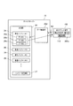
図5は、タブレット端末に表示されるユーザーインターフェイスを示す図である。図5(A)は、タッチパネル101aに表示された第1ユーザーインターフェイスU1の一例を示す図である。また、図5(B)はタッチパネル102aに表示された第2ユーザーインターフェイスU2の一例を示す図である。   FIG. 5 is a diagram illustrating a user interface displayed on the tablet terminal. FIG. 5A is a diagram illustrating an example of the first user interface U1 displayed on the touch panel 101a. FIG. 5B shows an example of the second user interface U2 displayed on the touch panel 102a.

図5(A)の第1ユーザーインターフェイスU1の左上部には、顧客が購入した商品の名称、商品の単価、及び、商品の数量が一覧表示される一覧表示エリア39が表示されている。一覧表示エリア39の右方には、顧客が購入した商品の合計金額、会計に際して顧客から預かった金銭の金額、及び、顧客に渡すべきお釣りの金額が表示される金額表示エリア40が表示されている。
一覧表示エリア39の下方には、バーコードスキャナー12によって読み取られたバーコードが表す情報(以下、「バーコード情報」という。)が入力され表示される入力フィールドであるバーコード情報入力フィールド41が形成されている。バーコード情報は、基本的には、商品の種類毎に一意に割り当てられた識別情報である。
バーコード情報入力フィールド41の下方には、カードリーダー13によって顧客の会員カードが読み取られた場合に、当該読み取りによって取得される会員番号が入力され表示される入力フィールドである会員番号入力フィールド42が表示されている。
バーコード情報入力フィールド41、及び、会員番号入力フィールド42の右方には、ソフトウェアテンキー43が表示されている。第1ユーザーインターフェイスU1に形成された入力フィールドのそれぞれに対しては、ソフトウェアテンキー43を介して情報を入力することが可能となっており、ソフトウェアテンキー43は、情報の入力に必要なキーを有している。
第1ユーザーインターフェイスU1の上端部には、アクセス先のアドレスが表示されるアドレス入力フィールド44が表示されている。
In the upper left part of the first user interface U1 in FIG. 5A, a list display area 39 in which the name of the product purchased by the customer, the unit price of the product, and the quantity of the product are displayed as a list is displayed. On the right side of the list display area 39, there is displayed an amount display area 40 for displaying the total amount of products purchased by the customer, the amount of money deposited from the customer at the time of accounting, and the amount of fishing to be given to the customer. Yes.
Below the list display area 39, there is a barcode information input field 41, which is an input field in which information (hereinafter referred to as "barcode information") represented by the barcode read by the barcode scanner 12 is input and displayed. Is formed. Bar code information is basically identification information uniquely assigned to each type of product.
Below the bar code information input field 41 is a member number input field 42 which is an input field for inputting and displaying a member number acquired by the card reader 13 when the customer's member card is read. It is displayed.
On the right side of the barcode information input field 41 and the member number input field 42, a software numeric keypad 43 is displayed. Information can be input to each of the input fields formed on the first user interface U1 via the software numeric keypad 43. The software numeric keypad 43 has keys necessary for inputting information. doing.
An address input field 44 for displaying an access destination address is displayed at the upper end portion of the first user interface U1.

次に、第2タブレット端末102について説明する。上述したとおり、第2タブレット端末102は、顧客に会計に係る各種情報を提供するカスタマーディスプレイとしての機能を有する端末である。
会計に係る処理が行われる前に、レジのオペレーターまたは他の従事者は、第2タブレット端末102のブラウザーを起動し、タッチパネル102aへのタッチ操作により第2ユーザーインターフェイスU2の表示を指示する。当該指示に応じて、第2ブラウザー実行部262aは、POSサーバー17の所定のアドレスにアクセスし、HTMLファイル等のウェブページのデータを取得し、当該データに基づいて第2ユーザーインターフェイスU2を表示する。
Next, the second tablet terminal 102 will be described. As described above, the second tablet terminal 102 is a terminal having a function as a customer display that provides various information related to accounting to a customer.
Before the processing related to the accounting is performed, the cashier operator or another worker activates the browser of the second tablet terminal 102 and instructs the display of the second user interface U2 by a touch operation on the touch panel 102a. In response to the instruction, the second browser execution unit 262a accesses a predetermined address of the POS server 17, acquires web page data such as an HTML file, and displays the second user interface U2 based on the data. .

図5(B)の第2ユーザーインターフェイスU2の最上部には、顧客が購入した商品の名称、商品の単価、及び、商品の数量が一覧表示される購入商品表示エリア55が表示されている。購入商品表示エリア55の下方には、顧客が購入した商品の合計金額が表示される合計金額表示エリア56が配置される。さらに、合計金額表示エリア56の下方には、会計に際して顧客から預かった金銭の金額が表示される預かり金額表示エリア57が配置される。金額表示エリア57の下方には、顧客に渡すべきお釣りの金額が表示される釣銭金額表示エリア58が表示されている。
また、第2ユーザーインターフェイスU2の下部には情報表示エリア59が配置されている。情報表示エリア59は、上述した例のように通信部20bが外部サーバー2(図3)から取得した気象情報が表示されるエリアである。
At the top of the second user interface U2 in FIG. 5B, a purchased product display area 55 is displayed in which the name of the product purchased by the customer, the unit price of the product, and the quantity of the product are displayed in a list. Below the purchased product display area 55, a total price display area 56 in which the total price of products purchased by the customer is displayed. Further, below the total amount display area 56, a deposit amount display area 57 in which the amount of money deposited from the customer at the time of accounting is displayed. Below the amount display area 57, a change amount display area 58 in which the amount of change to be delivered to the customer is displayed.
In addition, an information display area 59 is disposed below the second user interface U2. The information display area 59 is an area in which weather information acquired from the external server 2 (FIG. 3) by the communication unit 20b is displayed as in the above-described example.

第2ユーザーインターフェイスU2の表示態様は、配置情報112により定義されている。購入商品表示エリア55、合計金額表示エリア56、金額表示エリア57、釣銭金額表示エリア58、及び情報表示エリア59の各エリアは、配信バッファー26の識別情報に対応づけられている。例えば、情報表示エリア59は#4の配信バッファー26に対応づけられ、#4の配信バッファー26に記憶された気象情報のデータを第2ブラウザー実行部262aが受信すると、情報表示エリア59に気象情報が表示される。デバイス制御部20から新たな気象情報のデータが送信されると、情報表示エリア59の表示は更新される。   The display mode of the second user interface U2 is defined by the arrangement information 112. Each of the purchased product display area 55, the total amount display area 56, the amount display area 57, the change amount display area 58, and the information display area 59 is associated with the identification information of the distribution buffer 26. For example, the information display area 59 is associated with the distribution buffer 26 of # 4, and when the second browser execution unit 262a receives the weather information data stored in the distribution buffer 26 of # 4, the weather information is displayed in the information display area 59. Is displayed. When new weather information data is transmitted from the device control unit 20, the display of the information display area 59 is updated.

図6は、POSシステム1の各装置の動作を示すフローチャートである。図7(A)はデバイスサーバー18の動作を示し、(B)は第1タブレット端末101の動作を示し、(C)はPOSサーバー17の動作を示し、(D)は第2タブレット端末102の動作を示す。また、図7は、タブレット端末に表示されるユーザーインターフェイスを示す図であり、図7(A)は第1ユーザーインターフェイスU1を示し、(B)は第2ユーザーインターフェイスU2を示す。   FIG. 6 is a flowchart showing the operation of each device of the POS system 1. 7A shows the operation of the device server 18, FIG. 7B shows the operation of the first tablet terminal 101, FIG. 7C shows the operation of the POS server 17, and FIG. 7D shows the operation of the second tablet terminal 102. The operation is shown. FIG. 7 is a diagram showing a user interface displayed on the tablet terminal. FIG. 7A shows the first user interface U1, and FIG. 7B shows the second user interface U2.

図6及び図7を参照して、顧客がある1つの商品を購入する場合を例に説明する。
まず、レジカウンターにおいて、レジの担当者は、バーコードスキャナー12によって、顧客が購入した1の商品に付されたバーコードを読み取る(ステップSX1)。
デバイス通信制御部20cは、無線デバイス通信部22を介して、バーコードスキャナー12の読み取り結果を示すデータを取得する(ステップSB11)。さらに、デバイス通信制御部20cは、読み取り結果を示すデータに基づいて、バーコード情報を示すデータ(入力データ)を生成し、当該バーコード情報を示すデータ(入力データ)を、通信部20bに出力する(ステップSB12)。通信部20bは、所定のプロトコルに準拠して、バーコード情報を示すデータ(入力データ)を、第1ブラウザー実行部261aに送信する(ステップSB13)。
With reference to FIG. 6 and FIG. 7, a case where a customer purchases one product will be described as an example.
First, at the register counter, the person in charge of the register reads the barcode attached to one product purchased by the customer by the barcode scanner 12 (step SX1).
The device communication control unit 20c acquires data indicating the reading result of the barcode scanner 12 via the wireless device communication unit 22 (step SB11). Further, the device communication control unit 20c generates data (input data) indicating the barcode information based on the data indicating the reading result, and outputs the data (input data) indicating the barcode information to the communication unit 20b. (Step SB12). The communication unit 20b transmits data (input data) indicating the barcode information to the first browser execution unit 261a in accordance with a predetermined protocol (step SB13).

バーコード情報を示すデータ(入力データ)が入力されると、第1ブラウザー実行部261aは、第1ユーザーインターフェイスU1に係るHTMLファイルに実装されたプログラム(以下、単に「スクリプト」という。)の機能により、バーコード情報入力フィールド41にバーコード情報を入力する(ステップSA11)。次いで、第1ブラウザー実行部261aは、スクリプトの機能により、アプリケーション実行部30aと通信し、バーコード情報が示す商品の商品名称、単価を問い合わせる(ステップSA12)。当該問い合わせを受けたアプリケーション実行部30aは、アプリケーション35の機能により、適宜、適切なデータベースにアクセスし、必要な情報を取得し、取得した情報を第1ブラウザー実行部261aに出力する(ステップSE11)。   When data indicating barcode information (input data) is input, the first browser execution unit 261a functions as a program (hereinafter simply referred to as “script”) implemented in an HTML file related to the first user interface U1. Thus, the barcode information is input to the barcode information input field 41 (step SA11). Next, the first browser execution unit 261a communicates with the application execution unit 30a using the script function to inquire about the product name and unit price of the product indicated by the barcode information (step SA12). Upon receiving the inquiry, the application execution unit 30a appropriately accesses an appropriate database by the function of the application 35, acquires necessary information, and outputs the acquired information to the first browser execution unit 261a (step SE11). .

第1ブラウザー実行部261aは、スクリプトの機能により、顧客が購入した商品の名称、商品の単価、及び、商品の数量を一覧表示エリア39に表示し、金額表示エリア40の所定の欄に、顧客が購入した商品の合計金額を表示する(ステップSA13)。次いで、レジの担当者によって、ソフトウェアテンキー43を介して会計すべき商品を確定する旨の操作が行われると、顧客から代金の預かり、及び、お釣りの返却が行われる。これに伴い第1タブレット端末101が操作され、第1ブラウザー実行部261aは、スクリプトの機能によってアプリケーション実行部30aと通信し、金額表示エリア40の欄に情報を表示する(ステップSA14)。   The first browser execution unit 261a displays the name of the product purchased by the customer, the unit price of the product, and the quantity of the product in the list display area 39 by the script function, and displays the customer in a predetermined column of the price display area 40. Displays the total amount of goods purchased (step SA13). Next, when the cashier in charge performs an operation for confirming the product to be checked through the software numeric keypad 43, the customer deposits the money and returns the change. Accordingly, the first tablet terminal 101 is operated, and the first browser execution unit 261a communicates with the application execution unit 30a by the script function, and displays information in the amount display area 40 (step SA14).

図7(A)は、ステップSA14が完了した時点での、第1ユーザーインターフェイスU1の一例を示す図である。図7(A)に示すように、ステップSA14が完了した時点では、第1ブラウザー実行部261aの機能(ブラウザーの機能)により、第1ユーザーインターフェイスU1に形成された各エリアに適切な情報が入力、表示された状態となる。   FIG. 7A is a diagram illustrating an example of the first user interface U1 at the time when Step SA14 is completed. As shown in FIG. 7A, when step SA14 is completed, appropriate information is input to each area formed in the first user interface U1 by the function (browser function) of the first browser execution unit 261a. Will be displayed.

第1ブラウザー実行部261aは、スクリプトの機能により、第2ユーザーインターフェイスU2に形成された各エリアに、情報を表示させる表示関連データを生成する(ステップSA15)。第1ブラウザー実行部261aは、デバイスサーバー18が送信した入力データに基づいて表示データを生成する。第1ブラウザー実行部261aは、第1経路K1を介して、生成した表示関連データを通信部20bに送信する(ステップSA16)。
通信部20bは、表示関連データを受信すると、受信した表示関連データを、配信バッファー26に記憶する(ステップSB14)。そして、データ配信部20dは、配信バッファー26に記憶された表示関連データを、第2経路K2を介して、第2ブラウザー実行部262aに送信する(ステップSB15)。
The first browser execution unit 261a generates display related data for displaying information in each area formed in the second user interface U2 by the function of the script (step SA15). The first browser execution unit 261a generates display data based on the input data transmitted by the device server 18. The first browser execution unit 261a transmits the generated display related data to the communication unit 20b via the first route K1 (Step SA16).
When receiving the display related data, the communication unit 20b stores the received display related data in the distribution buffer 26 (step SB14). Then, the data distribution unit 20d transmits the display related data stored in the distribution buffer 26 to the second browser execution unit 262a via the second path K2 (step SB15).

この表示関連データは、例えば、JSON(Java Script Object Notation)で記述されたデータであって、第2ユーザーインターフェイスU2の各エリアに表示されるデータである。具体的には、表示関連データには、顧客が購入した商品に係る商品名、単価、及び、数量を示す情報がプロトコルに準拠して記述されている。このデータは第2ユーザーインターフェイスU2の購入商品表示エリア55に表示すべき情報であり、通信部20bにより、配信バッファー26に記憶される。配信バッファー26は、配置情報112によって、購入商品表示エリア55に対応づけられており、後述するように購入商品表示エリア55に表示される。同様に、表示関連データには、合計金額表示エリア56に表示される情報である、顧客が購入した商品の合計金額を示す情報が記述されている。また、預かり金額表示エリア57に表示する情報である、会計に際して顧客から預かった金銭の金額を示す情報が記述されている。また、釣銭金額表示エリア58に表示する情報である、顧客に渡すべきお釣りの金額を示す情報が記述されている。周知の通り、JSONで記述されたデータは、JavaScript(登録商標)等、ウェブページに係るHTMLファイル上に実装されたスクリプトで処理可能である。このため、本実施形態のように、ブラウザーの機能によって実現される第1ブラウザー実行部261aから、第2ブラウザー実行部262aへと送信するデータの態様として用いることができる。なお、他の形式のデータをやり取りする構成であってもよい。   This display related data is, for example, data described in JSON (Java Script Object Notation) and is displayed in each area of the second user interface U2. Specifically, in the display-related data, information indicating the product name, unit price, and quantity related to the product purchased by the customer is described according to the protocol. This data is information to be displayed in the purchased product display area 55 of the second user interface U2, and is stored in the distribution buffer 26 by the communication unit 20b. The distribution buffer 26 is associated with the purchased product display area 55 by the arrangement information 112 and is displayed in the purchased product display area 55 as described later. Similarly, the display related data describes information indicating the total price of products purchased by the customer, which is information displayed in the total price display area 56. In addition, information indicating the amount of money deposited from the customer at the time of accounting, which is information displayed in the deposit amount display area 57, is described. In addition, information indicating the amount of change to be given to the customer, which is information displayed in the change amount display area 58, is described. As is well known, data described in JSON can be processed by a script mounted on an HTML file related to a web page, such as JavaScript (registered trademark). For this reason, like this embodiment, it can use as a mode of the data transmitted from the 1st browser execution part 261a realized by the function of a browser to the 2nd browser execution part 262a. In addition, the structure which exchanges the data of another format may be sufficient.

第2ブラウザー実行部262aは、表示関連データを受信すると(ステップSC11)、スクリプトの機能により、JSONで記述された表示関連データを解析する(ステップSC12)。そして、第2ブラウザー実行部262aは、表示関連データが記憶されていた配信バッファー26の識別情報と、配置情報112とに基づき、第2ユーザーインターフェイスU2の各エリアに、当該データにて指定された情報を表示する(ステップSC13)。   When the second browser execution unit 262a receives the display related data (step SC11), the second browser execution unit 262a analyzes the display related data described in JSON by the script function (step SC12). Then, the second browser execution unit 262a designates each area of the second user interface U2 with the data based on the identification information of the distribution buffer 26 in which the display related data is stored and the arrangement information 112. Information is displayed (step SC13).

図7(B)は、ステップSC13が完了した時点での、第2ユーザーインターフェイスU2の一例を示す図である。図7(B)に示すように、第2ブラウザー実行部262aは、受信した表示関連データに基づき、配置情報112に従って、第2ユーザーインターフェイスU2の各エリアに情報を表示する。このため、会計を行った顧客は、タッチパネル102aに表示された第2ユーザーインターフェイスU2を視認することにより、会計に係る各種情報を、確認することが可能となる。特に、本実施形態では、従来の数十×数百ドットのドットマトリクス式の表示パネルからなるカスタマーディスプレイと異なり、タブレット端末である第2タブレット端末102のタッチパネル102aに会計に係る情報が表示される。これにより、大容量の情報を、高精細でダイナミックな表示部により表示した上で、顧客に提供することが可能である。   FIG. 7B is a diagram illustrating an example of the second user interface U2 at the time when Step SC13 is completed. As shown in FIG. 7B, the second browser execution unit 262a displays information in each area of the second user interface U2 according to the arrangement information 112 based on the received display related data. For this reason, the customer who made the transaction can check various information related to the transaction by visually recognizing the second user interface U2 displayed on the touch panel 102a. In particular, in this embodiment, unlike a conventional customer display comprising a dot matrix type display panel of several tens of several hundred dots, information related to accounting is displayed on the touch panel 102a of the second tablet terminal 102 which is a tablet terminal. . As a result, a large amount of information can be displayed on the high-definition and dynamic display unit and then provided to the customer.

その後、第1ブラウザー実行部261aは、スクリプトの機能により、プリンターユニット21によって発行させるレシートに関する情報が含まれたXMLドキュメント(データ)を生成する(ステップSA17)。当該XMLドキュメントには、XMLに係るフォーマットに準拠して、レシートに印刷する文字や画像の情報等、レシートを発行するのに必要な情報が含まれている。第1ブラウザー実行部261aは、所定のプロトコルに準拠して、生成したXMLドキュメントを、通信部20bに送信する(ステップSA18)。
第1ブラウザー実行部261aによるXMLドキュメントの送信に応じて、通信部20bは、XMLドキュメントを受信すると共に(ステップSB16)、プリンターユニット制御部20aに出力する(ステップSB17)。
プリンターユニット制御部20aは、入力されたXMLドキュメントに基づいて、プリンターユニット21のコマンド体系に準拠した制御コマンドであって、プリンターユニット21にレシートの発行に係る各種処理を行わせる制御コマンドを生成し、プリンターユニット21に出力する(ステップSB18)。プリンターユニット21の制御回路は、制御コマンドに基づいて、各種機構を制御し、レシートを発行する(ステップSB19)。
Thereafter, the first browser execution unit 261a generates an XML document (data) including information on a receipt issued by the printer unit 21 by using a script function (step SA17). The XML document includes information necessary for issuing a receipt, such as information on characters and images to be printed on a receipt, in accordance with an XML format. The first browser execution unit 261a transmits the generated XML document to the communication unit 20b in accordance with a predetermined protocol (step SA18).
In response to the transmission of the XML document by the first browser execution unit 261a, the communication unit 20b receives the XML document (step SB16) and outputs it to the printer unit control unit 20a (step SB17).
Based on the input XML document, the printer unit control unit 20a generates a control command that conforms to the command system of the printer unit 21 and causes the printer unit 21 to perform various processes related to the receipt issuance. And output to the printer unit 21 (step SB18). Based on the control command, the control circuit of the printer unit 21 controls various mechanisms and issues a receipt (step SB19).

POSシステム1では、デバイスサーバー18が第2タブレット端末102に送信したデータを、第2タブレット端末102の要求により再送できる。
図8は、POSシステム1におけるデータ再送動作の説明図である。また、図9はデータ再送に係るPOSシステム1の動作を示す。図9(A)はデバイスサーバー18の動作を示し、図9(B)は第2タブレット端末102の動作を示す。
In the POS system 1, the data transmitted from the device server 18 to the second tablet terminal 102 can be retransmitted in response to a request from the second tablet terminal 102.
FIG. 8 is an explanatory diagram of a data retransmission operation in the POS system 1. FIG. 9 shows the operation of the POS system 1 related to data retransmission. FIG. 9A shows the operation of the device server 18, and FIG. 9B shows the operation of the second tablet terminal 102.

第2ブラウザー実行部262aは、データ配信部20dから送信されたデータの受信に失敗した場合に、第2経路K2を介してデータの再送を要求する(ステップSC21)。第2ブラウザー実行部262aが再送を要求する場合とは、例えば、データ配信部20dから送信されたデータが所定のフォーマットに適合しないデータである場合、もしくはデータ配信部20dからデータを受信しない時間が設定された時間に達した場合である。
第2ブラウザー実行部262aが送信する要求は、データの再送を要求するコマンドであり、再送するデータが記憶されている配信バッファー26の識別情報を含んでもよい。また、単にデータの再送信を要求する情報のみで構成されたコマンドであってもよい。
If the second browser execution unit 262a fails to receive the data transmitted from the data distribution unit 20d, the second browser execution unit 262a requests retransmission of the data via the second route K2 (step SC21). The case where the second browser execution unit 262a requests retransmission is, for example, when the data transmitted from the data distribution unit 20d is data that does not conform to a predetermined format, or when the data is not received from the data distribution unit 20d. This is when the set time is reached.
The request transmitted by the second browser execution unit 262a is a command for requesting retransmission of data, and may include identification information of the distribution buffer 26 in which the data to be retransmitted is stored. Further, it may be a command composed only of information for requesting retransmission of data.

データ配信部20dは、第2ブラウザー実行部262aからデータの再送が要求された場合に、この要求を受信して(ステップSB21)、配信バッファー26内のデータを取得する(ステップSB22)。ここで、図8に示すように、第2ブラウザー実行部262aがデータの再送信を要求するコマンドに配信バッファー26の識別情報を含めて送信した場合、データ配信部20dは、識別情報に該当する配信バッファー26内のデータを読み出す。例えば、第2タブレット端末102に#1〜#3の3つの配信バッファー26が対応付けられている場合、第2ブラウザー実行部262aは、これら3つの配信バッファー26の一部のみについて、データの再送信を要求できる。ここで、データ配信部20dは、第2ブラウザー実行部262aからコマンドを受信し、受信したコマンドに配信バッファー26の識別情報が含まれている場合、バッファー対応情報27に基づいて再送信の可否を判定してもよい。すなわち、データ配信部20dは、第2タブレット端末102から受信したコマンドの識別情報が指定する配信バッファー26が、バッファー対応情報27で当該第2タブレット端末102に対応付けられていない場合、データの再送信を拒否してもよい。この場合、バッファー対応情報27により対応付けられていないデータの配信を防止できる。
また、第2ブラウザー実行部262aが配信バッファー26の識別情報を含まないコマンドのみを送信して要求した場合、データ配信部20dは、この第2タブレット端末102に対してバッファー対応情報27で対応づけられた配信バッファー26内のデータを読み出す。具体的には、データ配信部20dは、データの再送信の要求コマンドを受信した場合に、コマンドを送信した第2タブレット端末102のIPOHアドレス等に基づき、第2タブレット端末102を特定する。そして、データ配信部20dは、特定した第2タブレット端末102にバッファー対応情報27で対応付けられている配信バッファー26を特定し、これらの配信バッファー26内のデータを送信する。
When the second browser execution unit 262a requests data retransmission, the data distribution unit 20d receives this request (step SB21) and acquires the data in the distribution buffer 26 (step SB22). Here, as illustrated in FIG. 8, when the second browser execution unit 262a transmits the command requesting retransmission of data including the identification information of the distribution buffer 26, the data distribution unit 20d corresponds to the identification information. Data in the distribution buffer 26 is read. For example, when the three distribution buffers 26 of # 1 to # 3 are associated with the second tablet terminal 102, the second browser execution unit 262a regenerates data for only a part of these three distribution buffers 26. You can request transmission. Here, the data distribution unit 20d receives the command from the second browser execution unit 262a, and when the received command includes the identification information of the distribution buffer 26, the data distribution unit 20d determines whether or not retransmission is possible based on the buffer correspondence information 27. You may judge. That is, if the distribution buffer 26 specified by the command identification information received from the second tablet terminal 102 is not associated with the second tablet terminal 102 in the buffer correspondence information 27, the data distribution unit 20d You may refuse transmission. In this case, distribution of data that is not associated with the buffer correspondence information 27 can be prevented.
In addition, when the second browser execution unit 262a transmits and requests only a command that does not include the identification information of the distribution buffer 26, the data distribution unit 20d associates the second tablet terminal 102 with the buffer correspondence information 27. The data in the distribution buffer 26 is read out. Specifically, when receiving a data retransmission request command, the data distribution unit 20d identifies the second tablet terminal 102 based on the IPOH address or the like of the second tablet terminal 102 that has transmitted the command. Then, the data distribution unit 20d identifies the distribution buffer 26 associated with the identified second tablet terminal 102 by the buffer correspondence information 27, and transmits the data in the distribution buffer 26.

データ配信部20dは、配信バッファー26から読み出したデータを、例えば、更新された時間が新しいデータから順に、第2ブラウザー実行部262aに送信する(ステップSB23)。ここで、データ配信部20dは、再送するデータに、このデータが格納されていた配信バッファー26の識別情報を付加してもよい。
第2ブラウザー実行部262aは、再送されたデータを受信し(ステップSC22)、配置情報112に基づいて受信したデータを表示パネル102cに表示する(ステップSC23)。
The data distribution unit 20d transmits the data read from the distribution buffer 26 to the second browser execution unit 262a, for example, in order from the newest updated time (step SB23). Here, the data distribution unit 20d may add identification information of the distribution buffer 26 in which the data is stored to the data to be retransmitted.
The second browser execution unit 262a receives the retransmitted data (step SC22), and displays the received data on the display panel 102c based on the arrangement information 112 (step SC23).

このようにデータを再送することにより、ホスト装置11と第2タブレット端末102との間の通信が途絶または障害を発生した場合であっても、第2タブレット端末102にデータを表示できる。POSシステム1は商品販売に係る会計処理を行い、第2タブレット端末102に会計処理に関する情報を表示する。このため、表示が行われないと顧客に不便を与え、店舗にとって望ましくない。データの再送を行うことで、このような不利益を回避できる。   By retransmitting data in this way, data can be displayed on the second tablet terminal 102 even when communication between the host device 11 and the second tablet terminal 102 is interrupted or a failure occurs. The POS system 1 performs accounting processing related to merchandise sales, and displays information related to accounting processing on the second tablet terminal 102. For this reason, if the display is not performed, it is inconvenient for the customer and is not desirable for the store. Such a disadvantage can be avoided by retransmitting the data.

配信バッファー26には、図8に示すように、通信部20bが記憶させた複数のデータを記憶可能である。各々の配信バッファー26は、記憶部25の記憶容量等に基づいて、容量が割り当てられている。配信バッファー26には、割り当てられた容量で、複数のデータが記憶される。すなわち、通信部20bは、第2タブレット端末102に送信するデータを配信バッファー26に追記し、既に配信バッファー26に記憶されているデータを削除または上書きしない。通信部20bがデータを配信バッファー26に記憶させる際に、配信バッファー26の容量を超える場合には、既に配信バッファー26に記憶されているデータの古いデータが消去され、或いは上書きされる。
データ配信部20dは、第2ブラウザー実行部262aにより再送が要求された場合に、該当する配信バッファー26内のデータを第2ブラウザー実行部262aに送信するので、デバイス制御部20と第2タブレット端末102との間の通信に、長時間の障害が発生した場合であっても、第2タブレット端末102により正しい情報を表示できる。
As shown in FIG. 8, the distribution buffer 26 can store a plurality of data stored by the communication unit 20b. Each distribution buffer 26 is assigned a capacity based on the storage capacity of the storage unit 25 and the like. The distribution buffer 26 stores a plurality of data with the allocated capacity. That is, the communication unit 20b appends data to be transmitted to the second tablet terminal 102 to the distribution buffer 26, and does not delete or overwrite data already stored in the distribution buffer 26. When the communication unit 20b stores data in the distribution buffer 26, if the capacity of the distribution buffer 26 is exceeded, the old data already stored in the distribution buffer 26 is erased or overwritten.
Since the data distribution unit 20d transmits the data in the corresponding distribution buffer 26 to the second browser execution unit 262a when a retransmission is requested by the second browser execution unit 262a, the device control unit 20 and the second tablet terminal Even when a long-time failure occurs in communication with the mobile phone 102, correct information can be displayed by the second tablet terminal 102.

以上説明したように、本実施形態に係るPOSシステム1は、POS端末として動作して決済処理を行う第1タブレット端末101と、データに基づいて出力を行う第2タブレット端末102と、ホスト装置11と、を備える。ホスト装置11は、第2タブレット端末102にデータを送信するサーバーインターフェイス32を有する。また、ホスト装置11は、データを記憶する配信バッファー26を含み、配信バッファー26と第2タブレット端末102とを対応づけるバッファー対応情報27を記憶する記憶部25を有する。また、ホスト装置11は、第1タブレット端末101の決済処理に基づいてデータを取得して配信バッファー26に記憶させる通信部20bを有する。また、ホスト装置11は、通信部20bが配信バッファー26にデータを記憶させた場合に、記憶されたデータをバッファー対応情報27で配信バッファー26に対応づけられた第2タブレット端末102に送信するデータ配信部20dを備える。
これにより、第1タブレット端末101の決済処理に基づくデータがホスト装置11から第2タブレット端末102に対し、第2タブレット端末102がホスト装置11にデータを要求する手順を経ることなく送信される。また、データが送信される第2タブレット端末102を、配信バッファー26との対応づけによって設定できる。このため、第2タブレット端末102へ出力するデータや、データの出力先となる第2タブレット端末102を任意に決めることができ、第2タブレット端末102を個別に制御できる。
As described above, the POS system 1 according to the present embodiment includes the first tablet terminal 101 that operates as a POS terminal and performs payment processing, the second tablet terminal 102 that performs output based on data, and the host device 11. And comprising. The host device 11 has a server interface 32 that transmits data to the second tablet terminal 102. The host device 11 includes a distribution buffer 26 that stores data, and includes a storage unit 25 that stores buffer correspondence information 27 that associates the distribution buffer 26 with the second tablet terminal 102. In addition, the host device 11 includes a communication unit 20 b that acquires data based on the payment process of the first tablet terminal 101 and stores the data in the distribution buffer 26. In addition, when the communication unit 20 b stores data in the distribution buffer 26, the host device 11 transmits the stored data to the second tablet terminal 102 associated with the distribution buffer 26 using the buffer correspondence information 27. A distribution unit 20d is provided.
As a result, data based on the settlement process of the first tablet terminal 101 is transmitted from the host device 11 to the second tablet terminal 102 without going through a procedure in which the second tablet terminal 102 requests data from the host device 11. Further, the second tablet terminal 102 to which data is transmitted can be set by associating with the distribution buffer 26. Therefore, the data to be output to the second tablet terminal 102 and the second tablet terminal 102 that is the data output destination can be arbitrarily determined, and the second tablet terminal 102 can be individually controlled.

また、第2タブレット端末102とホスト装置11とがウェブソケット接続され、データ配信部20dは、接続された第2タブレット端末102を配信バッファー26に対応づけるバッファー対応情報27を生成する。これにより、ホスト装置11に第2タブレット端末102がウェブソケット接続されると、この第2タブレット端末102がバッファー対応情報27により配信バッファー26に対応づけられる。従って、第2タブレット端末102がホスト装置11にウェブソケット接続された後に、ホスト装置11が取得したデータを第2タブレット端末102へ送信できる。   In addition, the second tablet terminal 102 and the host device 11 are connected by web socket, and the data distribution unit 20 d generates buffer correspondence information 27 that associates the connected second tablet terminal 102 with the distribution buffer 26. As a result, when the second tablet terminal 102 is connected to the host device 11 via the web socket, the second tablet terminal 102 is associated with the distribution buffer 26 by the buffer correspondence information 27. Therefore, after the second tablet terminal 102 is connected to the host device 11 by web socket, the data acquired by the host device 11 can be transmitted to the second tablet terminal 102.

また、POSシステム1は、第1タブレット端末101にデータを入力するバーコードスキャナー12、カードリーダー13などの入力デバイスを備える。通信部20bが取得して配信バッファー26に記憶させるデータは、入力デバイスによりPOS端末に入力されたデータ、もしくは、第1タブレット端末101が入力装置により入力されたデータに基づいて決済処理したデータである。これにより、バーコードスキャナー12やカードリーダー13により第1タブレット端末101に入力されたデータ、もしくは、第1タブレット端末101が決済処理した決済処理データが第2タブレット端末102に送信される。このため、入力データまたは決済処理データの出力先となる第2タブレット端末102を任意に決定できる。   The POS system 1 also includes input devices such as a barcode scanner 12 and a card reader 13 that input data to the first tablet terminal 101. The data acquired by the communication unit 20b and stored in the distribution buffer 26 is data input to the POS terminal by the input device or data processed by the first tablet terminal 101 based on the data input by the input device. is there. Thereby, the data input to the first tablet terminal 101 by the barcode scanner 12 or the card reader 13 or the payment processing data processed by the first tablet terminal 101 is transmitted to the second tablet terminal 102. For this reason, the 2nd tablet terminal 102 used as the output destination of input data or payment process data can be determined arbitrarily.

また、記憶部25は配信バッファー26を複数有し、通信部20bが受信して配信バッファー26に記憶させるデータは、当該データを記憶する配信バッファー26を指定する情報を含んでいてもよい。この場合、通信部20bは、第1ブラウザー実行部261aから受信したデータに含まれる情報により指定された配信バッファー26にデータを記憶させる。この場合、第1ブラウザー実行部261aにより配信バッファー26を指定することができ、さらに、このデータを送信する送信先の第2タブレット端末102を指定できる。
また、通信部20bが受信して配信バッファー26に記憶させるデータは、当該データの属性を示す属性情報を含んでいてもよい。この場合、通信部20bは、第1ブラウザー実行部261aから受信したデータの属性に対応する配信バッファー26にデータを記憶させる。この場合、通信部20bが受信したデータが送信される第2タブレット端末102が、このデータの属性によって決定される。従って、任意の出力装置にデータを送信できる。
The storage unit 25 includes a plurality of distribution buffers 26, and the data received by the communication unit 20b and stored in the distribution buffer 26 may include information specifying the distribution buffer 26 that stores the data. In this case, the communication unit 20b stores the data in the distribution buffer 26 specified by the information included in the data received from the first browser execution unit 261a. In this case, the distribution buffer 26 can be designated by the first browser execution unit 261a, and further, the second tablet terminal 102 that is the transmission destination for transmitting this data can be designated.
Further, the data received by the communication unit 20b and stored in the distribution buffer 26 may include attribute information indicating the attribute of the data. In this case, the communication unit 20b stores the data in the distribution buffer 26 corresponding to the data attribute received from the first browser execution unit 261a. In this case, the second tablet terminal 102 to which the data received by the communication unit 20b is transmitted is determined by the attribute of this data. Therefore, data can be transmitted to any output device.

また、第2タブレット端末102の第2ブラウザー実行部262aは、デバイスサーバー18から送信されたデータを受信して表示パネル102cにより表示させる。ここで、バッファー対応情報27が、第2ブラウザー実行部262aがデータを表示する表示形態に係る情報を含んでいてもよい。この場合、第2ブラウザー実行部262aは、バッファー対応情報27に含まれる表示形態に係る情報に基づいて、デバイスサーバー18から受信したデータを表示させる。この場合、デバイスサーバー18が第1タブレット端末101から受信したデータを、第2タブレット端末102により任意の表示形態で表示させることができる。
また、第2タブレット端末102は配置情報112を有し、デバイスサーバー18から受信したデータを配置情報112に基づいて決定した表示形態で表示してもよい。この場合、デバイスサーバー18が表示形態を指定しなくても、予め設定された表示形態で第2タブレット端末102がデータを表示できる。
In addition, the second browser execution unit 262a of the second tablet terminal 102 receives the data transmitted from the device server 18 and causes the display panel 102c to display the data. Here, the buffer correspondence information 27 may include information relating to a display form in which the second browser execution unit 262a displays data. In this case, the second browser execution unit 262a displays the data received from the device server 18 based on the information related to the display form included in the buffer correspondence information 27. In this case, the data received by the device server 18 from the first tablet terminal 101 can be displayed by the second tablet terminal 102 in an arbitrary display form.
Further, the second tablet terminal 102 may have the arrangement information 112 and display the data received from the device server 18 in a display form determined based on the arrangement information 112. In this case, even if the device server 18 does not designate a display form, the second tablet terminal 102 can display data in a preset display form.

なお、上述した実施の形態は、あくまでも本発明の一態様を示すものであり、本発明の範囲内で任意に変形および応用が可能である。
例えば、上述した実施形態では、データ配信部20dが、配信バッファー26に記憶されたデータを、第2タブレット端末102にプッシュ送信する構成を例に挙げて説明した。本発明はこれに限定されず、例えば、出力装置は、プリンターユニット21であってもよいし、外部のプリンターであってもよい。すなわち、データ配信部20dが、プリンターユニット21や他のプリンターにデータをプッシュ送信し、このデータを受信したプリンターユニット21や他のプリンターが、予め設定された情報に基づきデータを配置して印刷を行ってもよい。
また、ホスト装置11に表示装置を接続し、デバイス制御部20がプログラムを実行することにより、第2タブレット端末102と同様に動作する仮想の端末装置を形成することも可能である。具体的には、デバイス制御部20を構成するCPUがプログラムを実行することで、第2タブレット端末102の第2端末制御部262と同様にブラウザーを実行する。この仮想の端末は、デバイス制御部20の通信部20b及びデータ配信部20dには、1つの第2タブレット端末102として扱われる。この仮想の端末と通信部20bとの間の通信は、実際はデバイス制御部20の内部におけるデータ通信となるが、この通信路において第2経路K2が形成される。上記仮想の端末は、バッファー対応情報27により、配信バッファー26に対応づけられ、第2経路K2を介してデータ配信部20dから送信されるデータを受信して表示する。これにより、ホスト装置11が第2タブレット端末102にプッシュ送信するデータを、ホスト装置11に接続された出力装置(例えば、ディスプレイ)に出力させることができる。同様の方法により、第1タブレット端末101において、第2タブレット端末102と同様に動作する仮想の端末を設けてもよい。
The above-described embodiment is merely an aspect of the present invention, and can be arbitrarily modified and applied within the scope of the present invention.
For example, in the above-described embodiment, the configuration in which the data distribution unit 20d push-transmits the data stored in the distribution buffer 26 to the second tablet terminal 102 has been described as an example. The present invention is not limited to this. For example, the output device may be the printer unit 21 or an external printer. That is, the data distribution unit 20d pushes data to the printer unit 21 or another printer, and the printer unit 21 or other printer that has received this data arranges the data based on preset information and performs printing. You may go.
It is also possible to form a virtual terminal device that operates in the same manner as the second tablet terminal 102 by connecting a display device to the host device 11 and executing the program by the device control unit 20. Specifically, the CPU configuring the device control unit 20 executes the program, thereby executing the browser in the same manner as the second terminal control unit 262 of the second tablet terminal 102. This virtual terminal is handled as one second tablet terminal 102 by the communication unit 20b and the data distribution unit 20d of the device control unit 20. The communication between the virtual terminal and the communication unit 20b is actually data communication inside the device control unit 20, but the second path K2 is formed in this communication path. The virtual terminal is associated with the distribution buffer 26 based on the buffer correspondence information 27, and receives and displays data transmitted from the data distribution unit 20d via the second path K2. Thereby, the data that the host device 11 push-transmits to the second tablet terminal 102 can be output to an output device (for example, a display) connected to the host device 11. A virtual terminal that operates similarly to the second tablet terminal 102 may be provided in the first tablet terminal 101 by the same method.

また、本実施形態では、ホスト装置11が、POSサーバー17及びデバイスサーバー18の機能を実現する構成として説明したが、POSサーバー17とデバイスサーバー18とを別個の装置として構成することも勿論可能である。さらに、通信部20b及びデータ配信部20dの機能のうち、第1タブレット端末101や外部から取得したデータを配信バッファー26に記憶し、第2タブレット端末102にプッシュ送信する機能を、POSサーバー17が実行する構成としてもよい。また、当該機能を、ホスト装置11とは別の装置により実行させてもよい。
また例えば、図2に示す各機能ブロックはハードウェアとソフトウェアの協働により任意に実現可能であり、特定のハードウェア構成を示唆するものではない。また、各機器は、外部接続される記憶媒体に記憶させたプログラムを実行することにより、各種動作を実行してもよい。
In the present embodiment, the host device 11 has been described as a configuration that realizes the functions of the POS server 17 and the device server 18, but it is of course possible to configure the POS server 17 and the device server 18 as separate devices. is there. Further, among the functions of the communication unit 20b and the data distribution unit 20d, the POS server 17 has a function of storing the data acquired from the first tablet terminal 101 or the outside in the distribution buffer 26 and push-transmitting it to the second tablet terminal 102. It may be configured to execute. Further, the function may be executed by a device different from the host device 11.
Further, for example, each functional block shown in FIG. 2 can be arbitrarily realized by cooperation of hardware and software, and does not suggest a specific hardware configuration. Each device may execute various operations by executing a program stored in an externally connected storage medium.

1…POSシステム、11…ホスト装置、12…バーコードスキャナー(入力装置)、13…カードリーダー(入力装置)、17…POSサーバー、18…デバイスサーバー(サーバー装置)、20…デバイス制御部、20a…プリンターユニット制御部、20b…通信部、20c…デバイス通信制御部、20d…データ配信部(送信制御部、対応情報制御部)、25…記憶部、26…配信バッファー(記憶領域)、27…バッファー対応情報(対応情報)、30…POSサーバー制御部、30a…アプリケーション実行部、31…POSサーバー記憶部、32…サーバーインターフェイス(送信部)、35…アプリケーション、101…第1タブレット端末(POS端末装置)、101c…表示パネル、102…第2タブレット端末(出力装置)、102c…表示パネル(表示部)、112…配置情報、261…第1端末制御部、261a…第1ブラウザー実行部、262…第2端末制御部、262a…第2ブラウザー実行部(出力制御部)。   DESCRIPTION OF SYMBOLS 1 ... POS system, 11 ... Host device, 12 ... Bar code scanner (input device), 13 ... Card reader (input device), 17 ... POS server, 18 ... Device server (server device), 20 ... Device control part, 20a ... printer unit control unit, 20b ... communication unit, 20c ... device communication control unit, 20d ... data distribution unit (transmission control unit, correspondence information control unit), 25 ... storage unit, 26 ... delivery buffer (storage area), 27 ... Buffer correspondence information (correspondence information), 30 ... POS server control unit, 30a ... Application execution unit, 31 ... POS server storage unit, 32 ... Server interface (transmission unit), 35 ... Application, 101 ... First tablet terminal (POS terminal) Device), 101c ... display panel, 102 ... second tablet terminal (output) , 102c... Display panel (display unit), 112... Arrangement information, 261... First terminal control unit, 261 a... First browser execution unit, 262... Second terminal control unit, 262 a. Control unit).

Claims (8)

決済処理を行うPOS端末装置と、
データに基づいて出力を行う出力装置と、
前記出力装置に前記データを送信する送信部、前記データを記憶する記憶領域を含んで前記記憶領域と前記出力装置とを対応づける対応情報を記憶する記憶部、前記POS端末装置の前記決済処理に基づいて前記データを取得して前記データを前記記憶領域に記憶させる記憶制御部、及び、前記記憶制御部が前記記憶領域に前記データを記憶させた場合に前記対応情報で前記記憶領域と対応づけられた前記出力装置に前記記憶領域に記憶された前記データを送信する送信制御部を有するサーバー装置と、
を備えることを特徴とするPOSシステム。
A POS terminal device that performs payment processing;
An output device for outputting based on the data;
A transmission unit for transmitting the data to the output device, a storage unit for storing correspondence information that associates the storage region with the output device, including a storage region for storing the data, and the settlement processing of the POS terminal device A storage control unit that acquires the data based on the data and stores the data in the storage area; and the storage control unit associates the storage area with the storage information when the storage control unit stores the data in the storage area. A server device having a transmission control unit for transmitting the data stored in the storage area to the output device,
A POS system comprising:
前記出力装置と前記サーバー装置とをウェブソケット接続し、
前記サーバー装置は、前記記憶領域と前記出力装置とを対応づける前記対応情報を生成する対応情報制御部を有する請求項1記載のPOSシステム。
A web socket connection between the output device and the server device;
The POS system according to claim 1, wherein the server device includes a correspondence information control unit that generates the correspondence information that associates the storage area with the output device.
前記POS端末装置に入力データを送信する入力装置を備え、
前記データは、前記入力装置で送信された前記入力データ、もしくは前記入力データに基づいて前記決済処理された決済処理データである請求項1または2記載のPOSシステム。
An input device for transmitting input data to the POS terminal device;
3. The POS system according to claim 1, wherein the data is the input data transmitted by the input device or the payment processing data that has been subjected to the payment processing based on the input data.
前記記憶部は、前記記憶領域を複数含み、
前記データは、前記記憶領域を指定する指定情報を有し、
前記記憶制御部は、前記指定情報に基づいて、複数の前記記憶領域のうちの指定された前記記憶領域に記憶させる請求項1から3のいずれか1項に記載のPOSシステム。
The storage unit includes a plurality of the storage areas,
The data has designation information for designating the storage area,
The POS system according to any one of claims 1 to 3, wherein the storage control unit stores the specified storage area in the plurality of storage areas based on the specification information.
前記記憶部は、前記記憶領域を複数含み、
前記データは、属性情報を有し、
前記記憶制御部は、前記属性情報に基づいて複数の前記記憶領域のうちで前記データを記憶させる前記記憶領域を選択する請求項1から3のいずれか1項に記載のPOSシステム。
The storage unit includes a plurality of the storage areas,
The data has attribute information;
4. The POS system according to claim 1, wherein the storage control unit selects the storage area in which the data is stored from among the plurality of storage areas based on the attribute information. 5.
前記出力装置は、表示を行う表示部、及び、前記データに基づいて前記表示部で表示させる出力制御部を有する表示装置であり、
前記対応情報は、前記出力装置の表示形態に係る情報を有し、
前記出力制御部は、前記データを前記対応情報が有する前記表示形態に係る情報に対応して前記表示部に表示させる請求項1から5のいずれか1項に記載のPOSシステム。
The output device is a display device that has a display unit that performs display, and an output control unit that displays on the display unit based on the data,
The correspondence information includes information relating to a display form of the output device,
The POS system according to any one of claims 1 to 5, wherein the output control unit displays the data on the display unit in correspondence with information related to the display form included in the correspondence information.
決済処理を行うPOS端末装置、及び、データに基づいて出力を行う出力装置と通信を行うサーバー装置であって、
前記出力装置に前記データを送信する送信部と、
前記データを記憶する記憶領域を有し、前記記憶領域と前記出力装置とを対応づける対応情報を記憶する記憶部と、
前記POS端末装置の前記決済処理に基づいて前記データを取得して前記データを前記記憶領域に記憶させる記憶制御部と、
前記記憶制御部が前記記憶領域に前記データを記憶させた場合に、前記記憶領域に記憶された前記データを前記対応情報で前記記憶領域と対応づけられた前記出力装置に送信する送信制御部と、
を備えることを特徴とするサーバー装置。
A server device that communicates with a POS terminal device that performs payment processing and an output device that performs output based on data;
A transmission unit that transmits the data to the output device,
A storage unit that stores the data; and a storage unit that stores correspondence information that associates the storage region with the output device;
A storage control unit for acquiring the data based on the settlement process of the POS terminal device and storing the data in the storage area;
A transmission control unit for transmitting the data stored in the storage area to the output device associated with the storage area by the correspondence information when the storage control unit stores the data in the storage area; ,
A server apparatus comprising:
決済処理を行うPOS端末装置、及び、データに基づいて出力を行う出力装置と通信を行うサーバー装置の制御方法であって、
前記データを記憶する記憶領域を有する記憶部に、前記記憶領域と前記出力装置とを対応づける対応情報を記憶させ、
前記POS端末装置の前記決済処理に基づいて前記データを取得し、
取得した前記データを前記記憶部の所定の前記記憶領域に記憶させ、
定の前記記憶領域に前記データを記憶させたとき、前記対応情報で前記記憶領域と対応づけられた出力装置へ前記記憶領域に記憶された前記データを送信すること、
を特徴とするサーバー装置の制御方法。
A control method for a POS terminal device that performs payment processing and a server device that communicates with an output device that performs output based on data,
In a storage unit having a storage area for storing the data, correspondence information that associates the storage area with the output device is stored,
Acquires the data based on the settlement processing of the POS terminal device,
The obtained the data is stored in a predetermined said memory area of said storage unit,
After programming the data in the storage area of Jo Tokoro, and transmitting the data stored the to the corresponding information in association was output device and the storage area in the storage area,
A method for controlling a server device .
JP2013178388A 2013-08-29 2013-08-29 POS system, server device, and server device control method Expired - Fee Related JP6060858B2 (en)

Priority Applications (7)

Application Number Priority Date Filing Date Title
JP2013178388A JP6060858B2 (en) 2013-08-29 2013-08-29 POS system, server device, and server device control method
CN201480047127.7A CN105493056B (en) 2013-08-29 2014-08-22 Data transmission method for uplink used in POS system, printing equipment and POS system
US14/914,080 US10686881B2 (en) 2013-08-29 2014-08-22 Transmission system, transmission device, and data transmission method
EP14839936.3A EP3040870A4 (en) 2013-08-29 2014-08-22 Transmission system, transmission device, and data transmission method
RU2016111141A RU2016111141A (en) 2013-08-29 2014-08-22 TRANSMISSION SYSTEM, TRANSMISSION DEVICE AND METHOD OF DATA TRANSFER
KR1020157028248A KR101827936B1 (en) 2013-08-29 2014-08-22 Transmission system, transmission device, and data transmission method
PCT/JP2014/004340 WO2015029406A1 (en) 2013-08-29 2014-08-22 Transmission system, transmission device, and data transmission method

Applications Claiming Priority (1)

Application Number Priority Date Filing Date Title
JP2013178388A JP6060858B2 (en) 2013-08-29 2013-08-29 POS system, server device, and server device control method

Related Child Applications (1)

Application Number Title Priority Date Filing Date
JP2016242937A Division JP6304357B2 (en) 2016-12-15 2016-12-15 Receipt issuing device and method for controlling receipt issuing device

Publications (3)

Publication Number Publication Date
JP2015046135A JP2015046135A (en) 2015-03-12
JP2015046135A5 JP2015046135A5 (en) 2016-05-19
JP6060858B2 true JP6060858B2 (en) 2017-01-18

Family

ID=52671554

Family Applications (1)

Application Number Title Priority Date Filing Date
JP2013178388A Expired - Fee Related JP6060858B2 (en) 2013-08-29 2013-08-29 POS system, server device, and server device control method

Country Status (1)

Country Link
JP (1) JP6060858B2 (en)

Family Cites Families (8)

* Cited by examiner, † Cited by third party
Publication number Priority date Publication date Assignee Title
JPH11232055A (en) * 1998-02-17 1999-08-27 Minolta Co Ltd Print system
JP3772952B2 (en) * 1999-10-01 2006-05-10 セイコーエプソン株式会社 Display device, control method thereof, and information recording medium
JP4606216B2 (en) * 2005-03-24 2011-01-05 富士通セミコンダクター株式会社 Communication data control device
JP2007108868A (en) * 2005-10-11 2007-04-26 Toshiba Tec Corp Merchandise information processing system
JP4847212B2 (en) * 2006-05-29 2011-12-28 キヤノン株式会社 Information processing apparatus, print control method, program, and computer-readable storage medium
JP5515498B2 (en) * 2009-08-05 2014-06-11 セイコーエプソン株式会社 CONTROL DEVICE, CONTROL DEVICE CONTROL METHOD, PROGRAM
JP2012118733A (en) * 2010-11-30 2012-06-21 Canon Inc Printing system, printing method and program
JP5729039B2 (en) * 2011-03-15 2015-06-03 株式会社リコー Information processing system, server device, client terminal, installation method, program, printer driver, and recording medium

Also Published As

Publication number Publication date
JP2015046135A (en) 2015-03-12

Similar Documents

Publication Publication Date Title
KR101827936B1 (en) Transmission system, transmission device, and data transmission method
JP6681210B2 (en) Checkout system, registration device and its program
JP6572884B2 (en) POS system and control method of POS system
KR20140141631A (en) Control system, method for controlling control system, and recording device
WO2014076930A1 (en) Pos system and printer
JP5935400B2 (en) Control system, control method of control system, and printer
JP6028416B2 (en) Data processing apparatus and POS system
JP6107542B2 (en) Transmission system, transmission apparatus, and data transmission method
JP6304357B2 (en) Receipt issuing device and method for controlling receipt issuing device
US10776767B2 (en) Checkout system and registration device
JP6060858B2 (en) POS system, server device, and server device control method
JP6172333B2 (en) Program and information processing apparatus control method
JP6167764B2 (en) Transmission system, printing apparatus, and data transmission method
EP2866213B1 (en) Display system.
JP6323528B2 (en) Data processing apparatus, data processing system, and control method for data processing apparatus
JP6928141B2 (en) Checkout system and registration device and control program
JP6916014B2 (en) Information processing device and display control program
JP6160437B2 (en) POS system, host device, and host device control method
EP3336809A1 (en) Settlement apparatus, checkout system and method
JP6160436B2 (en) POS system, host device, and host device control method
JP6171837B2 (en) Transmission system, transmission apparatus, and data transmission method

Legal Events

Date Code Title Description
A521 Request for written amendment filed

Free format text: JAPANESE INTERMEDIATE CODE: A523

Effective date: 20160328

A621 Written request for application examination

Free format text: JAPANESE INTERMEDIATE CODE: A621

Effective date: 20160328

A131 Notification of reasons for refusal

Free format text: JAPANESE INTERMEDIATE CODE: A131

Effective date: 20160809

A521 Request for written amendment filed

Free format text: JAPANESE INTERMEDIATE CODE: A523

Effective date: 20161007

TRDD Decision of grant or rejection written
A01 Written decision to grant a patent or to grant a registration (utility model)

Free format text: JAPANESE INTERMEDIATE CODE: A01

Effective date: 20161115

A61 First payment of annual fees (during grant procedure)

Free format text: JAPANESE INTERMEDIATE CODE: A61

Effective date: 20161128

R150 Certificate of patent or registration of utility model

Ref document number: 6060858

Country of ref document: JP

Free format text: JAPANESE INTERMEDIATE CODE: R150

LAPS Cancellation because of no payment of annual fees