JP6050002B2 - Laser processing method - Google Patents
Laser processing method Download PDFInfo
- Publication number
- JP6050002B2 JP6050002B2 JP2012018600A JP2012018600A JP6050002B2 JP 6050002 B2 JP6050002 B2 JP 6050002B2 JP 2012018600 A JP2012018600 A JP 2012018600A JP 2012018600 A JP2012018600 A JP 2012018600A JP 6050002 B2 JP6050002 B2 JP 6050002B2
- Authority
- JP
- Japan
- Prior art keywords
- cutting line
- workpiece
- along
- crack
- modified region
- Prior art date
- Legal status (The legal status is an assumption and is not a legal conclusion. Google has not performed a legal analysis and makes no representation as to the accuracy of the status listed.)
- Active
Links
Images


Landscapes
- Laser Beam Processing (AREA)
- Re-Forming, After-Treatment, Cutting And Transporting Of Glass Products (AREA)
- Processing Of Stones Or Stones Resemblance Materials (AREA)
Description
本発明は、強化ガラス板を備える板状の加工対象物から有効部を切り出すためのレーザ加工方法に関する。 The present invention relates to a laser processing method for cutting out an effective portion from a plate-like processing object including a tempered glass plate.
上記技術分野のレーザ加工方法として、板状の加工対象物にレーザ光を照射することにより、切断予定ラインに沿って加工対象物の内部に改質領域を形成し、その改質領域から発生した亀裂を加工対象物の厚さ方向に伸展させることにより、切断予定ラインに沿って加工対象物を切断するものが知られている(例えば、特許文献1参照)。 As a laser processing method in the above technical field, a plate-shaped workpiece is irradiated with a laser beam, thereby forming a modified region inside the workpiece along the planned cutting line, and generated from the modified region. It is known that a workpiece is cut along a planned cutting line by extending a crack in the thickness direction of the workpiece (for example, see Patent Document 1).
しかしながら、上述したようなレーザ加工方法を実施することにより、強化ガラス板を備える板状の加工対象物から、面取りされた角部を有する有効部を切り出そうとすると、角部にバリ等が生じて、角部おいて切断品質が低下する場合がある。 However, by carrying out the laser processing method as described above, when trying to cut out an effective portion having a chamfered corner portion from a plate-like workpiece having a tempered glass plate, there is a burr or the like at the corner portion. This may cause cutting quality to deteriorate at the corners.
そこで、本発明は、強化ガラス板を備える板状の加工対象物から、面取りされた角部を有する有効部を精度良く切り出すことができるレーザ加工方法を提供することを目的とする。 Then, an object of this invention is to provide the laser processing method which can cut out the effective part which has the chamfered corner | angular part accurately from the plate-shaped process target provided with a tempered glass board.
本発明のレーザ加工方法は、強化ガラス板を備える板状の加工対象物から、面取りされた角部を有する有効部を切り出すためのレーザ加工方法であって、少なくとも角部の面取り面に沿うように延在する第1切断予定ラインに沿って、レーザ光の集光点を相対的に移動させることにより、加工対象物の厚さ方向に伸展する第1亀裂を発生させる第1改質領域を、第1切断予定ラインに沿って強化ガラス板の内部に形成する第1工程と、第1工程の後に、有効部の外側から角部に至るように延在する第2切断予定ラインに沿って、レーザ光の集光点を相対的に移動させることにより、加工対象物の厚さ方向に伸展する第2亀裂を発生させる第2改質領域を、第2切断予定ラインに沿って強化ガラス板の内部に形成する第2工程と、を備える。 The laser processing method of the present invention is a laser processing method for cutting out an effective portion having a chamfered corner from a plate-like processing object including a tempered glass plate, and at least along the chamfered surface of the corner. A first modified region that generates a first crack extending in the thickness direction of the workpiece by relatively moving the condensing point of the laser light along the first scheduled cutting line extending to A first step formed inside the tempered glass plate along the first scheduled cutting line, and a second planned cutting line extending from the outside of the effective portion to the corner after the first step. The second modified region that generates the second crack extending in the thickness direction of the object to be processed by relatively moving the condensing point of the laser beam, the tempered glass plate along the second scheduled cutting line 2nd process formed in the inside.
このレーザ加工方法では、角部の面取り面に沿うように延在する第1切断予定ラインに沿って第1改質領域を形成し、その後に、有効部の外側から角部に至るように延在する第2切断予定ラインに沿って第2改質領域を形成する。この順序で第1改質領域及び第2改質領域を形成すると、次の理由により、第1切断予定ラインに沿って精度良く第1亀裂が伸展し易くなる。すなわち、強化ガラス板は、引張応力層、及びその引張応力層の両側に形成された圧縮応力層を有するので、改質領域から亀裂が発生し易く且つ伸展し易い。そのため、第2改質領域を形成した後に第1改質領域を形成すると、第1改質領域から発生した第1亀裂の一部が第1切断予定ラインから外れて第2改質領域に向かって伸展し、角部にバリ等が生じ易くなる。これに対し、第1改質領域を形成した後に第2改質領域を形成すると、第1亀裂の一部が第2改質領域に向かって伸展するような事態が防止され、第1切断予定ラインに沿って精度良く第1亀裂が伸展し易くなる。よって、このレーザ加工方法によれば、強化ガラス板を備える板状の加工対象物から、面取りされた角部を有する有効部を精度良く切り出すことができる。 In this laser processing method, the first modified region is formed along the first scheduled cutting line extending along the chamfered surface of the corner portion, and then extended from the outside of the effective portion to the corner portion. A second modified region is formed along the existing second cutting scheduled line. When the first modified region and the second modified region are formed in this order, the first crack is easily extended along the first scheduled cutting line with the following reason. In other words, the tempered glass plate has a tensile stress layer and a compressive stress layer formed on both sides of the tensile stress layer, so that a crack is easily generated from the modified region and is easily extended. Therefore, when the first modified region is formed after the second modified region is formed, a part of the first crack generated from the first modified region deviates from the first scheduled cutting line toward the second modified region. It becomes easy to generate burrs at the corners. On the other hand, when the second modified region is formed after the first modified region is formed, a situation in which a part of the first crack extends toward the second modified region is prevented, and the first cutting scheduled The first crack is easily extended along the line with high accuracy. Therefore, according to this laser processing method, the effective part which has the chamfered corner | angular part can be accurately cut out from the plate-shaped process target provided with a tempered glass board.
ここで、第1工程では、第1亀裂を加工対象物の表面及び裏面に到達させ、第2工程では、第2亀裂を加工対象物の表面及び裏面に到達させてもよい。これによれば、第1亀裂の一部が第2改質領域に向かって伸展するような事態をより確実に防止して、第1切断予定ラインに沿って第1亀裂を伸展させることができる。 Here, in the first step, the first crack may reach the front surface and the back surface of the workpiece, and in the second step, the second crack may reach the front surface and the back surface of the workpiece. According to this, it is possible to more reliably prevent a situation in which a part of the first crack extends toward the second modified region, and it is possible to extend the first crack along the first scheduled cutting line. .
また、第1切断予定ラインが、有効部の側面のうち面取り面に至る有効部の端面に沿うように延在する場合には、第1切断予定ラインにおいて端面に沿うように延在する部分と連続するように第2切断予定ラインを設定してもよい。また、面取り面が凸曲面である場合には、第1切断予定ラインにおいて面取り面に沿うように延在する部分と接するように第2切断予定ラインを設定してもよい。これらによれば、例えば有効部の周囲の部分を切り落とすための第2切断予定ラインにおいても、第2改質領域から発生した第2亀裂の一部が第2切断予定ラインから外れて第1改質領域に向かって伸展するのを抑制することができる。 In addition, when the first scheduled cutting line extends along the end surface of the effective portion that reaches the chamfered surface of the side surface of the effective portion, the first cutting planned line extends along the end surface; You may set a 2nd cutting plan line so that it may continue. In addition, when the chamfered surface is a convex curved surface, the second scheduled cutting line may be set so as to be in contact with a portion extending along the chamfered surface in the first scheduled cutting line. According to these, for example, also in the second scheduled cutting line for cutting off the portion around the effective portion, a part of the second crack generated from the second modified region is removed from the second scheduled cutting line and the first modified It is possible to suppress extension toward the quality region.
また、上述したレーザ加工方法は、加工対象物から有効部を複数切り出す場合には、第1工程の前に、隣り合う有効部の間を通るように延在する第3切断予定ラインに沿って、レーザ光の集光点を相対的に移動させることにより、加工対象物の厚さ方向に伸展する第3亀裂を発生させる第3改質領域を、第3切断予定ラインに沿って強化ガラス板の内部に形成する第3工程を更に備えてもよい。これによれば、隣り合う有効部の一方において、第1及び第2改質領域から発生した第1及び第2亀裂の一部が、第1及び第2切断予定ラインから外れて、隣り合う有効部の他方に向かって伸展したとしても、第3改質領域及び第3亀裂によってその伸展が止められるため、隣り合う有効部の他方が損傷するのを防止することができる。 Further, in the laser processing method described above, when a plurality of effective portions are cut out from the workpiece, the third cutting scheduled line extending so as to pass between adjacent effective portions is provided before the first step. The third modified region that generates the third crack extending in the thickness direction of the object to be processed is moved along the third scheduled cutting line by relatively moving the condensing point of the laser beam. You may further provide the 3rd process formed inside. According to this, in one of the adjacent effective portions, a part of the first and second cracks generated from the first and second modified regions deviate from the first and second scheduled cutting lines and are adjacent to each other. Even if it extends toward the other side of the part, the extension is stopped by the third modified region and the third crack, so that the other of the adjacent effective parts can be prevented from being damaged.
このとき、第3工程では、第3亀裂を加工対象物の表面及び裏面に到達させてもよい。これによれば、第1及び第2切断予定ラインから外れた第1及び第2亀裂の一部の伸展をより確実に止めることができる。 At this time, in the third step, the third crack may reach the front surface and the back surface of the workpiece. According to this, extension of a part of the 1st and 2nd cracks which deviated from the 1st and 2nd scheduled cutting lines can be stopped more certainly.
本発明によれば、強化ガラス板を備える板状の加工対象物から、面取りされた角部を有する有効部を精度良く切り出すことができるレーザ加工方法を提供することが可能となる。 ADVANTAGE OF THE INVENTION According to this invention, it becomes possible to provide the laser processing method which can cut out the effective part which has the chamfered corner | angular part accurately from the plate-shaped process target provided with a tempered glass board.
以下、本発明の好適な実施形態について、図面を参照して詳細に説明する。なお、各図において同一又は相当部分には同一符号を付し、重複する説明を省略する。 DESCRIPTION OF EMBODIMENTS Hereinafter, preferred embodiments of the present invention will be described in detail with reference to the drawings. In addition, in each figure, the same code | symbol is attached | subjected to the same or an equivalent part, and the overlapping description is abbreviate | omitted.
本発明の一実施形態のレーザ加工方法では、切断予定ラインに沿って加工対象物にレーザ光を照射することにより、切断予定ラインに沿って加工対象物の内部に切断の起点となる改質領域を形成する。そこで、加工対象物の材料を限定せずに、改質領域の形成について、図1〜図6を参照して説明する。 In the laser processing method of one embodiment of the present invention, the modified region that is the starting point of cutting inside the workpiece along the planned cutting line by irradiating the processing target with laser light along the planned cutting line Form. Therefore, the formation of the modified region will be described with reference to FIGS. 1 to 6 without limiting the material of the workpiece.
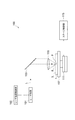
図1に示すように、レーザ加工装置100は、レーザ光Lをパルス発振するレーザ光源101と、レーザ光Lの光軸(光路)の向きを90°変えるように配置されたダイクロイックミラー103と、レーザ光Lを集光するための集光用レンズ105と、を備えている。また、レーザ加工装置100は、集光用レンズ105で集光されたレーザ光Lが照射される加工対象物1を支持するための支持台107と、支持台107を移動させるためのステージ111と、レーザ光Lの出力やパルス幅等を調節するためにレーザ光源101を制御するレーザ光源制御部102と、ステージ111の駆動を制御するステージ制御部115と、を備えている。
As shown in FIG. 1, a
このレーザ加工装置100においては、レーザ光源101から出射されたレーザ光Lは、ダイクロイックミラー103によってその光軸の向きを90°変えられ、支持台107上に載置された加工対象物1の内部に集光用レンズ105によって集光される。これと共に、ステージ111が移動させられ、加工対象物1がレーザ光Lに対して切断予定ライン5に沿って相対移動させられる。これにより、切断予定ライン5に沿った改質領域が加工対象物1に形成されることとなる。
In this
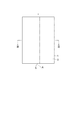
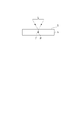
加工対象物1としては、種々の材料(例えば、ガラス、半導体材料、圧電材料等)からなる板状の部材(例えば、基板、ウェハ等)が用いられる。図2に示すように、加工対象物1には、加工対象物1を切断するための切断予定ライン5が設定されている。切断予定ライン5は、直線状に延びた仮想線である。加工対象物1の内部に改質領域を形成する場合、図3に示すように、加工対象物1の内部に集光点Pを合わせた状態で、レーザ光Lを切断予定ライン5に沿って(すなわち、図2の矢印A方向に)相対的に移動させる。これにより、図4〜図6に示すように、改質領域7が切断予定ライン5に沿って加工対象物1の内部に形成され、切断予定ライン5に沿って形成された改質領域7が切断起点領域8となる。
As the
なお、集光点Pとは、レーザ光Lが集光する箇所のことである。また、切断予定ライン5は、直線状に限らず曲線状であってもよいし、仮想線に限らず加工対象物1の表面3に実際に引かれた線であってもよい。また、改質領域7は、連続的に形成される場合もあるし、断続的に形成される場合もある。また、改質領域7は列状でも点状でもよく、要は、改質領域7は少なくとも加工対象物1の内部に形成されていればよい。また、改質領域7を起点に亀裂が形成される場合があり、亀裂及び改質領域7は、加工対象物1の外表面(表面、裏面、若しくは外周面)に露出していてもよい。
In addition, the condensing point P is a location where the laser light L is condensed. Further, the planned cutting line 5 is not limited to a straight line, but may be a curved line, or may be a line actually drawn on the
ちなみに、ここでのレーザ光Lは、加工対象物1を透過すると共に加工対象物1の内部の集光点近傍にて特に吸収され、これにより、加工対象物1に改質領域7が形成される(すなわち、内部吸収型レーザ加工)。よって、加工対象物1の表面3ではレーザ光Lが殆ど吸収されないので、加工対象物1の表面3が溶融することはない。一般的に、表面3から溶融され除去されて穴や溝等の除去部が形成される(表面吸収型レーザ加工)場合、加工領域は表面3側から徐々に裏面側に進行する。
Incidentally, the laser light L here passes through the
ところで、本実施形態で形成される改質領域は、密度、屈折率、機械的強度やその他の物理的特性が周囲とは異なる状態になった領域をいう。改質領域としては、例えば、溶融処理領域、クラック領域、絶縁破壊領域、屈折率変化領域等があり、これらが混在した領域もある。更に、改質領域としては、加工対象物の材料において改質領域の密度が非改質領域の密度と比較して変化した領域や、格子欠陥が形成された領域がある(これらをまとめて高密転移領域ともいう)。 By the way, the modified region formed in the present embodiment refers to a region where the density, refractive index, mechanical strength, and other physical characteristics are different from the surroundings. Examples of the modified region include a melt treatment region, a crack region, a dielectric breakdown region, a refractive index change region, and the like, and there is a region where these are mixed. Furthermore, as the modified region, there are a region in which the density of the modified region in the material to be processed is changed as compared with the density of the non-modified region, and a region in which lattice defects are formed (collectively these are high-density regions). Also known as the metastatic region).
また、溶融処理領域や屈折率変化領域、改質領域の密度が非改質領域の密度と比較して変化した領域、格子欠陥が形成された領域は、更に、それら領域の内部や改質領域と非改質領域との界面に亀裂(割れ、マイクロクラック等)を内包している場合がある。内包される亀裂は改質領域の全面に渡る場合や一部分のみや複数部分に形成される場合がある。加工対象物1としては、例えばシリコン、ガラス、LiTaO3又はサファイア(Al2O3)からなる基板やウェハ、又はそのような基板やウェハを含むものが挙げられる。
In addition, the area where the density of the melt treatment area, the refractive index change area, the modified area has changed compared to the density of the non-modified area, and the area where lattice defects are formed are further included in these areas and the modified areas. In some cases, cracks (cracks, microcracks, etc.) are included in the interface between the non-modified region and the non-modified region. The included crack may be formed over the entire surface of the modified region, or may be formed in only a part or a plurality of parts. Examples of the
また、本実施形態においては、切断予定ライン5に沿って改質スポット(加工痕)を複数形成することによって、改質領域7を形成している。改質スポットとは、パルスレーザ光の1パルスのショット(つまり1パルスのレーザ照射:レーザショット)で形成される改質部分であり、改質スポットが集まることにより改質領域7となる。改質スポットとしては、クラックスポット、溶融処理スポット若しくは屈折率変化スポット、又はこれらの少なくとも1つが混在するもの等が挙げられる。
Further, in the present embodiment, the modified
この改質スポットについては、要求される切断精度、要求される切断面の平坦性、加工対象物の厚さ、種類、結晶方位等を考慮して、その大きさや発生する亀裂の長さを適宜制御することが好ましい。
[第1実施形態]
Considering the required cutting accuracy, required flatness of the cut surface, thickness of the workpiece, type, crystal orientation, etc., the size of the modified spot and the length of the crack to be generated are appropriately determined. It is preferable to control.
[First Embodiment]
図7(a)に示すように、加工対象物1は、表面1a及び裏面1bを有する矩形板状の部材であり、強化ガラス板10を備えている。強化ガラス板10は、引張応力層、及びその引張応力層の両側に形成された圧縮応力層を有するガラス板である。強化ガラス板10は、通常のガラス(フロートガラス)板を溶融塩に浸漬させ、イオン交換によってガラス板の表面層に圧縮応力層を形成したり(イオン交換法)、通常のガラス板を加熱した後、ガラス板の表面に空気を吹き付けるなどしてガラス板を急冷させたり(風冷強化法)することで製造される。強化ガラス板10では、その厚さ方向が、引張応力層及び圧縮応力層の配列方向と一致している。
As illustrated in FIG. 7A, the
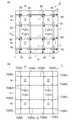
以上のように構成された加工対象物1から、以下のように、矩形板状の有効部17を複数(ここでは、4枚)切り出す。なお、図7(b)に示すように、有効部17は、表面17a及び裏面17b、並びに面取りされた4つの角部18を有するものであり、各角部18は、その面取り面18aが凸曲面となるようにR面取りされたものである。このような有効部17は、携帯型端末のディスプレイの保護基板等に用いられる。
A plurality (four in this case) of rectangular plate-shaped
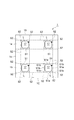
まず、加工対象物1をレーザ加工装置100の支持台107上に載置する。このとき、加工対象物1の裏面1bにテープを貼ったり、或いは支持台107を多孔質状に形成して加工対象物1を真空吸着したりするなど、支持台107上において加工対象物1を保持する。そして、加工対象物1に対し、第1切断予定ライン51(図7(a)における一点鎖線)、第2切断予定ライン52(図7(a)における破線)及び第3切断予定ライン53(図7(a)における二点鎖線)を設定する。
First, the
第1切断予定ライン51は、各有効部17の側面19(すなわち、各有効部17の4つの端面17c及び4つの面取り面18a)に沿うように延在している。環状に閉じた第1切断予定ライン51は、加工対象物1に対して複数行複数列(ここでは、2行2列)配置されている。各第1切断予定ライン51は、加工対象物1の側面1cから離間しており、隣り合う第1切断予定ライン51,51同士は、互いに離間している。
The first scheduled cutting
第2切断予定ライン52は、有効部17の外側から各角部18に至るように延在している。各第2切断予定ライン52は、第1切断予定ライン51において有効部17の端面17cに沿うように延在する部分51aと連続し、且つ第1切断予定ライン51において面取り面18aに沿うように延在する部分51bと接している。第2切断予定ライン52は、各有効部17の周囲の部分を切り落とすためのラインであるため、各第2切断予定ライン52は、加工対象物1の側面1cに至るか、或いは第3切断予定ライン53と交差している。
The second scheduled cutting
第3切断予定ライン53は、隣り合う有効部17,17の間を通るように延在している。行方向において隣り合う有効部17,17の間を通るように延在する第3切断予定ライン53は、列方向において対向する加工対象物1の側面1c,1cのそれぞれに至るように加工対象物1を横切っている。列方向において隣り合う有効部17,17の間を通るように延在する第3切断予定ライン53は、行方向において対向する加工対象物1の側面1c,1cのそれぞれに至るように加工対象物1を横切っている。
The third scheduled cutting
続いて、図8(a)に示すように、加工対象物1の表面1aをレーザ光入射面として強化ガラス板10の内部にレーザ光Lの集光点を位置させ、各第3切断予定ライン53に沿って加工対象物1にレーザ光Lを照射する。つまり、第3切断予定ライン53に沿ってレーザ光Lの集光点を相対的に移動(スキャン)させる。これにより、加工対象物1の厚さ方向に伸展する第3亀裂83を発生させる第3改質領域73を(図8(b)参照)、第3切断予定ライン53に沿って強化ガラス板10の内部に形成する(第3工程)。このとき、第3切断予定ライン53に対する第3改質領域73の形成に伴って(加工対象物1に何ら外力を作用させずに)、第3改質領域73から発生した第3亀裂83を加工対象物1の表面1a及び裏面1bに到達させる。
Subsequently, as shown in FIG. 8A, the condensing point of the laser light L is positioned inside the tempered
第3改質領域73を形成した後に、図8(b)に示すように、加工対象物1の表面1aをレーザ光入射面として強化ガラス板10の内部にレーザ光Lの集光点を位置させ、各第1切断予定ライン51に沿って加工対象物1にレーザ光Lを照射する。つまり、第1切断予定ライン51に沿ってレーザ光Lの集光点を相対的に移動(スキャン)させる。これにより、加工対象物1の厚さ方向に伸展する第1亀裂81を発生させる第1改質領域71を(図9(a)参照)、第1切断予定ライン51に沿って強化ガラス板10の内部に形成する(第1工程)。このとき、第1切断予定ライン51に対する第1改質領域71の形成に伴って(加工対象物1に何ら外力を作用させずに)、第1改質領域71から発生した第1亀裂81を加工対象物1の表面1a及び裏面1bに到達させる。
After the third modified
第1改質領域71を形成した後に、図9(a)に示すように、加工対象物1の表面1aをレーザ光入射面として強化ガラス板10の内部にレーザ光Lの集光点を位置させ、各第2切断予定ライン52に沿って加工対象物1にレーザ光Lを照射する。つまり、第2切断予定ライン52に沿ってレーザ光Lの集光点を相対的に移動(スキャン)させる。これにより、加工対象物1の厚さ方向に伸展する第2亀裂82を発生させる第2改質領域72を(図9(b)参照)、第2切断予定ライン52に沿って強化ガラス板10の内部に形成する(第2工程)。このとき、第2切断予定ライン52に対する第2改質領域72の形成に伴って(加工対象物1に何ら外力を作用させずに)、第2改質領域72から発生した第2亀裂82を加工対象物1の表面1a及び裏面1bに到達させる。
After forming the first modified
以上の順序で第1改質領域71、第2改質領域72及び第3改質領域73を形成することにより、図7(b)に示すように、各有効部17の周囲の部分を切り落として、矩形板状の有効部17を複数切り出す。なお、各切断予定ライン51,52,53に沿ってレーザ光Lの集光点を相対的に移動させるために、加工対象物1側(支持台107等)を移動させてもよいし、レーザ光L側(レーザ光源101、ダイクロイックミラー103及び集光用レンズ105等)を移動させてもよいし、或いは、加工対象物1側及びレーザ光L側の両方を移動させてもよい。また、支持台107上における加工対象物1の保持は、全ての改質領域71,72,73を形成した後に解除する。
By forming the first modified
以上説明したように、第1実施形態のレーザ加工方法では、有効部17の側面19(すなわち、有効部17の端面17c及び面取り面18a)に沿うように延在する第1切断予定ライン51に沿って第1改質領域71を形成し、その後に、有効部17の外側から角部18に至るように延在する第2切断予定ライン52に沿って第2改質領域72を形成する。この順序で第1改質領域71及び第2改質領域72を形成すると、次の理由により、第1切断予定ライン51において角部18の面取り面18aに沿うように延在する部分51bに沿って精度良く第1亀裂81が伸展し易くなる。すなわち、強化ガラス板10は、引張応力層、及びその引張応力層の両側に形成された圧縮応力層を有するので、改質領域71〜73から亀裂81〜83が発生し易く且つ伸展し易い。そのため、第2改質領域72を形成した後に第1改質領域71を形成すると、第1切断予定ライン51の部分51bでは、第1改質領域71から発生した第1亀裂81の一部が第1切断予定ライン51から外れて第2改質領域72に向かって伸展し(第2亀裂82に引っ張られるように伸展し)、角部18にバリ等が生じ易くなる。これに対し、第1改質領域71を形成した後に第2改質領域72を形成すると、第1亀裂81の一部が第2改質領域72に向かって伸展するような事態が防止され、第1切断予定ライン51に沿って精度良く第1亀裂81が伸展し易くなる。よって、第1実施形態のレーザ加工方法によれば、強化ガラス板10を備える板状の加工対象物1から、面取りされた角部18を有する有効部17を精度良く切り出すことができる。
As described above, in the laser processing method according to the first embodiment, the first cutting scheduled
特に、第1実施形態のレーザ加工方法では、第1改質領域71の形成に伴って第1亀裂81を加工対象物1の表面1a及び裏面1bに到達させ、第2改質領域72の形成に伴って第2亀裂82を加工対象物1の表面1a及び裏面1bに到達させているので、第1亀裂81の一部が第2改質領域72に向かって伸展するような事態がより確実に防止される。
In particular, in the laser processing method according to the first embodiment, the
また、第1実施形態のレーザ加工方法では、第1切断予定ライン51において有効部17の端面17cに沿うように延在する部分51aと連続し、且つ第1切断予定ライン51において角部18の面取り面18aに沿うように延在する部分51bと接するように、第2切断予定ライン52を設定する。これにより、有効部17の周囲の部分を切り落とすための第2切断予定ライン52においても、第2改質領域72から発生した第2亀裂82の一部が第2切断予定ライン52から外れて第1改質領域71に向かって伸展するのを抑制することができる。
Further, in the laser processing method of the first embodiment, the first cutting scheduled
また、第1実施形態のレーザ加工方法では、第1改質領域71を形成する前に、隣り合う有効部17,17の間を通るように延在する第3切断予定ライン53に沿って第3改質領域73を形成する。これにより、隣り合う有効部17,17の一方において、第1及び第2改質領域71,72から発生した第1及び第2亀裂81,82の一部が、第1及び第2切断予定ライン51,52から外れて、隣り合う有効部17,17の他方に向かって伸展したとしても、第3改質領域73及び第3亀裂81によってその伸展が止められるため、隣り合う有効部17,17の他方が損傷するのを防止することができる。
Further, in the laser processing method of the first embodiment, before forming the first modified
特に、第1実施形態のレーザ加工方法では、第3改質領域73の形成に伴って第3亀裂83を加工対象物1の表面1a及び裏面1bに到達させているので、第1及び第2切断予定ライン51,52から外れた第1及び第2亀裂81,82の一部の伸展がより確実に止められる。
In particular, in the laser processing method of the first embodiment, the
ところで、第1実施形態のレーザ加工方法では、第1切断予定ライン51に沿って環状にレーザ光Lの集光点を相対的に移動させる場合、次のように、レーザ光Lの繰返し周波数、及びレーザ光Lの集光点の相対的移動速度が調整される。すなわち、直線である部分51aでは、繰返し周波数Faで加工対象物1にレーザ光Lを照射すると共に、相対的移動速度Vaで集光点を相対的に移動させ、曲線である部分51bでは、繰返し周波数Faよりも低い繰返し周波数Fbで加工対象物1にレーザ光Lを照射すると共に、相対的移動速度Vaよりも低い相対的移動速度Vbで集光点を相対的に移動させる。これにより、周波数Faが50kHzであり、速度Vaが500mm/sであれば、部分51aにおけるレーザ光Lのパルスピッチ(速度Va/周波数Fa)は10μmとなる。また、周波数Fbが1kHzであり、速度Vbが10mm/sであれば、部分51bにおけるレーザ光Lのパルスピッチ(速度Vb/周波数Fb)は10μmとなる。
By the way, in the laser processing method of 1st Embodiment, when moving the condensing point of the laser beam L cyclically along the 1st
なお、レーザ光Lの繰返し周波数の調整は、例えば、レーザ光源101及びレーザ光源制御部102に超音波光変調器(AOM)等の光学素子を付加することにより実現される。この場合、レーザ光源101から出射されたレーザ光Lの繰返し周波数をAOMによって間引くことで、加工対象物1に照射されるレーザ光Lの繰返し周波数を低くすることができる。
Note that the adjustment of the repetition frequency of the laser light L is realized, for example, by adding an optical element such as an ultrasonic light modulator (AOM) to the
このように、曲線である部分51bに沿って(すなわち、有効部17の面取り面18aに沿って)第1改質領域71を形成する場合には、直線である部分51aに沿って(すなわち、有効部17の端面17cに沿って)第1改質領域71を形成する場合に比べ、レーザ光Lの集光点の相対的移動速度を低くする。これにより、有効部17に対して面取り面18aの外側をレーザ光Lの集光点が通るような事態を防止し、第1改質領域71を面取り面18aに沿って精度良く形成することができる。
As described above, when the first modified
更に、曲線である部分51bに沿って第1改質領域71を形成する場合には、直線である部分51aに沿って第1改質領域71を形成する場合に比べ、レーザ光Lの集光点の相対的移動速度を低くすることに加えて、レーザ光Lの繰返し周波数を低くする。レーザ光Lの繰返し周波数を低くせずにレーザ光Lの集光点の相対的移動速度を低くすると、パルスピッチが短くなるため、改質スポット(レーザ光Lの1パルスの照射で形成される改質部分)が密の状態で第1改質領域71が形成され、その結果、加工対象物1の厚さ方向に第1亀裂81が伸展し難くなるおそれがある。レーザ光Lの集光点の相対的移動速度を低くすると共にレーザ光Lの繰返し周波数を低くすることで、パルスピッチが短くなるのを防止し、有効部17の面取り面18aに沿った第1改質領域71を、第1亀裂81を伸展させ易いものとして形成することができる。
Further, when the first modified
また、第1実施形態のレーザ加工方法では、直線的に連続する第2切断予定ライン52及び第1切断予定ライン51の部分51aに沿ってレーザ光Lの集光点を相対的に移動させる場合、第2切断予定ライン52上を通過するときには、加工対象物1に対するレーザ光Lの照射をONとし、第1切断予定ライン51の部分51a上を通過するときには、加工対象物1に対するレーザ光Lの照射をOFFとする。これにより、第1切断予定ライン51の部分51aに沿って既に形成された第1改質領域71及び第1亀裂81にレーザ光Lが再度照射されることが防止される。従って、第1切断予定ライン51の部分51aに対応する有効部17の端面17cの切断品質が低下したり、有効部17の抗折強度が低下したりするのを防止することができる。なお、加工対象物1に対するレーザ光Lの照射のON/OFFの切替えも、例えば、上述した超音波光変調器(AOM)等の光学素子によって実現される。
[第2実施形態]
Further, in the laser processing method of the first embodiment, the condensing point of the laser light L is relatively moved along the linearly continuous second scheduled cutting
[Second Embodiment]
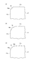
第2実施形態のレーザ加工方法は、加工対象物1に対して第3切断予定ライン53を設定しない点で、上述した第1実施形態のレーザ加工方法と主に相違している。第2実施形態のレーザ加工方法では、まず、図10(a)に示すように、加工対象物1に対し、第1切断予定ライン51(図10(a)における一点鎖線)及び第2切断予定ライン52(図10(a)における破線)を設定する。
The laser processing method of the second embodiment is mainly different from the laser processing method of the first embodiment described above in that the third cutting scheduled
第1切断予定ライン51は、各有効部17の側面19(すなわち、各有効部17の4つの端面17c及び4つの面取り面18a)に沿うように延在している。環状に閉じた第1切断予定ライン51は、加工対象物1に対して複数行複数列(ここでは、2行2列)配置されている。各第1切断予定ライン51は、加工対象物1の側面1cから離間しており、隣り合う第1切断予定ライン51,51同士は、互いに十分に(例えば、平面視における有効部17の幅以上)離間している。
The first scheduled cutting
第2切断予定ライン52は、有効部17の外側から各角部18に至るように延在している。各第2切断予定ライン52は、第1切断予定ライン51において有効部17の端面17cに沿うように延在する部分51aと連続し、且つ第1切断予定ライン51において面取り面18aに沿うように延在する部分51bと接している。第2切断予定ライン52は、各有効部17の周囲の部分を切り落とすためのラインであるため、各第2切断予定ライン52は、加工対象物1の側面1cに至っている。
The second scheduled cutting
続いて、図11に示すように、加工対象物1の表面1aをレーザ光入射面として強化ガラス板10の内部にレーザ光Lの集光点を位置させ、各第1切断予定ライン51に沿って加工対象物1にレーザ光Lを照射する。つまり、第1切断予定ライン51に沿ってレーザ光Lの集光点を相対的に移動(スキャン)させる。これにより、加工対象物1の厚さ方向に伸展する第1亀裂81を発生させる第1改質領域71を(図12(a)参照)、第1切断予定ライン51に沿って強化ガラス板10の内部に形成する(第1工程)。このとき、第1切断予定ライン51に対する第1改質領域71の形成に伴って(加工対象物1に何ら外力を作用させずに)、第1改質領域71から発生した第1亀裂81を加工対象物1の表面1a及び裏面1bに到達させる。
Subsequently, as shown in FIG. 11, the condensing point of the laser light L is positioned inside the tempered
第1改質領域71を形成した後に、図12(a)に示すように、加工対象物1の表面1aをレーザ光入射面として強化ガラス板10の内部にレーザ光Lの集光点を位置させ、各第2切断予定ライン52に沿って加工対象物1にレーザ光Lを照射する。つまり、第2切断予定ライン52に沿ってレーザ光Lの集光点を相対的に移動(スキャン)させる。これにより、加工対象物1の厚さ方向に伸展する第2亀裂82を発生させる第2改質領域72を(図12(b)参照)、第2切断予定ライン52に沿って強化ガラス板10の内部に形成する(第2工程)。このとき、第2切断予定ライン52に対する第2改質領域72の形成に伴って(加工対象物1に何ら外力を作用させずに)、第2改質領域72から発生した第2亀裂82を加工対象物1の表面1a及び裏面1bに到達させる。
After forming the first modified
以上の順序で第1改質領域71及び第2改質領域72を形成することにより、図10(b)に示すように、各有効部17の周囲の部分を切り落として、矩形板状の有効部17を複数切り出す。なお、各切断予定ライン51,52に沿ってレーザ光Lの集光点を相対的に移動させるために、加工対象物1側を移動させてもよいし、レーザ光L側を移動させてもよいし、或いは、加工対象物1側及びレーザ光L側の両方を移動させてもよい。また、支持台107上における加工対象物1の保持は、全ての改質領域71,72を形成した後に解除する。
By forming the first modified
以上説明したように、第2実施形態のレーザ加工方法では、有効部17の側面19(すなわち、有効部17の端面17c及び面取り面18a)に沿うように延在する第1切断予定ライン51に沿って第1改質領域71を形成し、その後に、有効部17の外側から角部18に至るように延在する第2切断予定ライン52に沿って第2改質領域72を形成する。よって、第2実施形態のレーザ加工方法によれば、第1実施形態のレーザ加工方法と同様の効果が奏される。
As described above, in the laser processing method according to the second embodiment, the first cutting scheduled
また、第2実施形態のレーザ加工方法では、隣り合う第1切断予定ライン51,51同士が互いに十分に(例えば、平面視における有効部17の幅以上)離間している。これにより、隣り合う有効部17,17の一方において、第1及び第2改質領域71,72から発生した第1及び第2亀裂81,82の一部が、第1及び第2切断予定ライン51,52から外れて、隣り合う有効部17,17の他方に向かって伸展したとしても、隣り合う有効部17,17の他方に到達し難くなるため、隣り合う有効部17,17の他方が損傷するのを防止することができる。
Further, in the laser processing method of the second embodiment, the adjacent first cutting scheduled
以上、本発明の第1及び第2実施形態について説明したが、本発明は、上記実施形態に限定されるものではない。例えば、加工対象物及び有効部の形状としては、矩形板状に限定されず、様々な形状を適用することができる。また、加工対象物から一つの有効部を切り出してもよい。 Although the first and second embodiments of the present invention have been described above, the present invention is not limited to the above-described embodiments. For example, the shapes of the processing object and the effective portion are not limited to a rectangular plate shape, and various shapes can be applied. Moreover, you may cut out one effective part from a process target object.
また、各切断予定ラインに対して、加工対象物の厚さ方向に並ぶように複数列の改質領域を形成してもよい。その場合にも、本発明によれば、面取りされた角部を有する有効部を板状の加工対象物から精度良く切り出すことができる。1本の切断予定ラインに対する改質領域の列数は、加工対象物の厚さ等に応じて適宜決定することができるものである。 In addition, a plurality of rows of modified regions may be formed so as to be aligned in the thickness direction of the workpiece with respect to each scheduled cutting line. Even in that case, according to the present invention, the effective portion having the chamfered corner portion can be accurately cut out from the plate-like workpiece. The number of columns of the modified region for one scheduled cutting line can be determined as appropriate according to the thickness of the workpiece.
また、上記実施形態では、各切断予定ラインに対する改質領域の形成に伴って(加工対象物に何ら外力を作用させずに)、改質領域から発生した亀裂を加工対象物の表面及び裏面に到達させたが、これに限定されない。つまり、改質領域の形成に伴って亀裂を発生されるだけで、加工対象物の表面及び裏面のいずれか一方に亀裂を到達させるだけでもよいし、或いは、加工対象物の表面及び裏面の両方に亀裂を到達させなくてもよい。これらの場合には、改質領域を形成した後に、切断予定ラインに沿って外力を作用させて、改質領域から発生した亀裂を加工対象物の表面及び裏面に到達させ、それにより、切断予定ラインに沿って加工対象物を切断すればよい。 Moreover, in the said embodiment, the crack which generate | occur | produced from the modification | reformation area | region with the formation of the modification | reformation area | region with respect to each cutting planned line (without applying any external force to a workpiece) on the surface and back surface of a workpiece. Although it was made to reach, it is not limited to this. In other words, only the crack is generated along with the formation of the modified region, and the crack may reach only one of the front surface and the back surface of the workpiece, or both the front and back surfaces of the workpiece are processed. It is not necessary to let the crack reach. In these cases, after forming the modified region, an external force is applied along the planned cutting line to cause the cracks generated from the modified region to reach the front and back surfaces of the workpiece, thereby cutting. What is necessary is just to cut | disconnect a process target object along a line.
また、図13に示すように、有効部17の角部18は、一つ又は複数の略平面である面取り面18aから構成されたものであってもよい。それらの場合にも、本発明によれば、面取り面から不要な方向に亀裂が伸展するのを防止し、面取りされた角部を有する有効部を板状の加工対象物から精度良く切り出すことができる。
Moreover, as shown in FIG. 13, the corner |
また、加工対象物は、強化ガラス板の表面及び裏面の少なくとも一方に樹脂膜等が形成されたものであってもよい。また、改質領域としては、レーザ光の照射条件等によって、溶融処理領域、クラック領域、絶縁破壊領域、屈折率変化領域等や、これらが混在した領域が形成される。 Further, the object to be processed may be one in which a resin film or the like is formed on at least one of the front surface and the back surface of the tempered glass plate. In addition, as the modified region, a melt-processed region, a crack region, a dielectric breakdown region, a refractive index change region, or a region in which these are mixed is formed depending on the irradiation condition of the laser beam.
1…加工対象物、1a…表面、1b…裏面、10…強化ガラス板、17…有効部、17c…端面、18…角部、18a…面取り面、19…側面、51…第1切断予定ライン、52…第2切断予定ライン、53…第3切断予定ライン、71…第1改質領域、72…第2改質領域、73…第3改質領域、81…第1亀裂、82…第2亀裂、83…第3亀裂、L…レーザ光、P…集光点。
DESCRIPTION OF
Claims (5)
少なくとも前記角部の面取り面に沿うように延在する第1切断予定ラインに沿って、レーザ光の集光点を相対的に移動させることにより、前記加工対象物の厚さ方向に伸展する第1亀裂を発生させる第1改質領域を、前記第1切断予定ラインに沿って前記強化ガラス板の内部に形成する第1工程と、
前記第1工程の後に、前記有効部の外側から前記角部に至るように延在する第2切断予定ラインに沿って、レーザ光の集光点を相対的に移動させることにより、前記加工対象物の厚さ方向に伸展する第2亀裂を発生させる第2改質領域を、前記第2切断予定ラインに沿って前記強化ガラス板の内部に形成する第2工程と、を備え、
前記加工対象物から前記有効部を複数切り出す場合には、前記第1工程の前に、隣り合う前記有効部の間を通るように延在する第3切断予定ラインに沿って、レーザ光の集光点を相対的に移動させることにより、前記加工対象物の厚さ方向に伸展する第3亀裂を発生させる第3改質領域を、前記第3切断予定ラインに沿って前記強化ガラス板の内部に形成する第3工程を更に備える、レーザ加工方法。 A laser processing method for cutting out an effective portion having a chamfered corner from a plate-like processing object including a tempered glass plate,
A laser beam condensing point is relatively moved along a first scheduled cutting line extending along at least the chamfered surface of the corner, thereby extending in the thickness direction of the workpiece. A first step of forming a first modified region for generating one crack in the tempered glass plate along the first scheduled cutting line;
After the first step, the processing target is moved by relatively moving a condensing point of the laser light along a second scheduled cutting line extending from the outside of the effective portion to the corner portion. A second step of forming a second modified region for generating a second crack extending in the thickness direction of the object inside the tempered glass plate along the second scheduled cutting line, and
In the case where a plurality of effective portions are cut out from the object to be processed, laser light is collected along a third scheduled cutting line extending so as to pass between adjacent effective portions before the first step. A third modified region that generates a third crack that extends in the thickness direction of the workpiece by moving the light spot relatively is formed inside the tempered glass plate along the third scheduled cutting line. The laser processing method further provided with the 3rd process formed in.
前記第2工程では、前記第2亀裂を前記加工対象物の前記表面及び前記裏面に到達させる、請求項1記載のレーザ加工方法。 In the first step, the first crack reaches the front surface and the back surface of the workpiece,
The laser processing method according to claim 1, wherein in the second step, the second crack is caused to reach the front surface and the back surface of the workpiece.
Priority Applications (1)
| Application Number | Priority Date | Filing Date | Title |
|---|---|---|---|
| JP2012018600A JP6050002B2 (en) | 2012-01-31 | 2012-01-31 | Laser processing method |
Applications Claiming Priority (1)
| Application Number | Priority Date | Filing Date | Title |
|---|---|---|---|
| JP2012018600A JP6050002B2 (en) | 2012-01-31 | 2012-01-31 | Laser processing method |
Publications (2)
| Publication Number | Publication Date |
|---|---|
| JP2013154604A JP2013154604A (en) | 2013-08-15 |
| JP6050002B2 true JP6050002B2 (en) | 2016-12-21 |
Family
ID=49050275
Family Applications (1)
| Application Number | Title | Priority Date | Filing Date |
|---|---|---|---|
| JP2012018600A Active JP6050002B2 (en) | 2012-01-31 | 2012-01-31 | Laser processing method |
Country Status (1)
| Country | Link |
|---|---|
| JP (1) | JP6050002B2 (en) |
Families Citing this family (6)
| Publication number | Priority date | Publication date | Assignee | Title |
|---|---|---|---|---|
| KR102421381B1 (en) | 2014-02-20 | 2022-07-18 | 코닝 인코포레이티드 | Methods and apparatus for cutting radii in flexible thin glass |
| CN106256519B (en) * | 2015-06-19 | 2019-09-24 | 上海和辉光电有限公司 | A kind of method of cutting substrate |
| US10562130B1 (en) | 2018-12-29 | 2020-02-18 | Cree, Inc. | Laser-assisted method for parting crystalline material |
| US10576585B1 (en) | 2018-12-29 | 2020-03-03 | Cree, Inc. | Laser-assisted method for parting crystalline material |
| US11024501B2 (en) | 2018-12-29 | 2021-06-01 | Cree, Inc. | Carrier-assisted method for parting crystalline material along laser damage region |
| US10611052B1 (en) | 2019-05-17 | 2020-04-07 | Cree, Inc. | Silicon carbide wafers with relaxed positive bow and related methods |
Family Cites Families (6)
| Publication number | Priority date | Publication date | Assignee | Title |
|---|---|---|---|---|
| JP2003088973A (en) * | 2001-09-12 | 2003-03-25 | Hamamatsu Photonics Kk | Laser beam machining method |
| AU2003220847A1 (en) * | 2003-03-12 | 2004-09-30 | Hamamatsu Photonics K.K. | Laser beam machining method |
| JP2004343008A (en) * | 2003-05-19 | 2004-12-02 | Disco Abrasive Syst Ltd | Workpiece dividing method utilizing laser beam |
| JP2006256944A (en) * | 2005-03-14 | 2006-09-28 | Lemi Ltd | Method and device for cutting brittle material |
| JP2010017990A (en) * | 2008-07-14 | 2010-01-28 | Seiko Epson Corp | Substrate dividing method |
| JP2011230940A (en) * | 2010-04-26 | 2011-11-17 | Mitsuboshi Diamond Industrial Co Ltd | Cutting method for brittle material substrate |
-
2012
- 2012-01-31 JP JP2012018600A patent/JP6050002B2/en active Active
Also Published As
| Publication number | Publication date |
|---|---|
| JP2013154604A (en) | 2013-08-15 |
Similar Documents
| Publication | Publication Date | Title |
|---|---|---|
| JP6059059B2 (en) | Laser processing method | |
| JP5597051B2 (en) | Laser processing method | |
| JP5864988B2 (en) | Tempered glass sheet cutting method | |
| JP5491761B2 (en) | Laser processing equipment | |
| JP5771391B2 (en) | Laser processing method | |
| JP5597052B2 (en) | Laser processing method | |
| JP6050002B2 (en) | Laser processing method | |
| TWI625186B (en) | Laser processing method and laser processing device | |
| JP2016513016A (en) | Method and apparatus for laser cutting transparent and translucent substrates | |
| US20110132885A1 (en) | Laser machining and scribing systems and methods | |
| WO2010116917A1 (en) | Laser machining device and laser machining method | |
| JP6012186B2 (en) | Processing object cutting method | |
| WO2006101091A1 (en) | Laser machining method | |
| WO2013039012A1 (en) | Laser machining method and laser machining device | |
| JP6012185B2 (en) | Manufacturing method of semiconductor device | |
| JP5361916B2 (en) | Laser scribing method | |
| JP5894754B2 (en) | Laser processing method | |
| JP2012240107A (en) | Laser processing method | |
| JP5969214B2 (en) | Manufacturing method of semiconductor device | |
| JP2013147380A (en) | Method for laser beam machining | |
| JP2014019610A (en) | Laser processing method | |
| JP2014091642A (en) | Laser processing method, and manufacturing method of electronic device | |
| TW201420249A (en) | Laser processing method and laser processing device | |
| JP2014177369A (en) | Manufacturing method of tempered glass member | |
| JP2014091641A (en) | Laser processing method, and manufacturing method of electronic device |
Legal Events
| Date | Code | Title | Description |
|---|---|---|---|
| A621 | Written request for application examination |
Free format text: JAPANESE INTERMEDIATE CODE: A621 Effective date: 20150126 |
|
| A131 | Notification of reasons for refusal |
Free format text: JAPANESE INTERMEDIATE CODE: A131 Effective date: 20160119 |
|
| A977 | Report on retrieval |
Free format text: JAPANESE INTERMEDIATE CODE: A971007 Effective date: 20160121 |
|
| A521 | Written amendment |
Free format text: JAPANESE INTERMEDIATE CODE: A523 Effective date: 20160308 |
|
| A131 | Notification of reasons for refusal |
Free format text: JAPANESE INTERMEDIATE CODE: A131 Effective date: 20160809 |
|
| A521 | Written amendment |
Free format text: JAPANESE INTERMEDIATE CODE: A523 Effective date: 20161007 |
|
| TRDD | Decision of grant or rejection written | ||
| A01 | Written decision to grant a patent or to grant a registration (utility model) |
Free format text: JAPANESE INTERMEDIATE CODE: A01 Effective date: 20161101 |
|
| A61 | First payment of annual fees (during grant procedure) |
Free format text: JAPANESE INTERMEDIATE CODE: A61 Effective date: 20161124 |
|
| R150 | Certificate of patent or registration of utility model |
Ref document number: 6050002 Country of ref document: JP Free format text: JAPANESE INTERMEDIATE CODE: R150 |