JP6042678B2 - Brake mechanism and medical manipulator having the same - Google Patents
Brake mechanism and medical manipulator having the same Download PDFInfo
- Publication number
- JP6042678B2 JP6042678B2 JP2012212061A JP2012212061A JP6042678B2 JP 6042678 B2 JP6042678 B2 JP 6042678B2 JP 2012212061 A JP2012212061 A JP 2012212061A JP 2012212061 A JP2012212061 A JP 2012212061A JP 6042678 B2 JP6042678 B2 JP 6042678B2
- Authority
- JP
- Japan
- Prior art keywords
- brake
- brake rotor
- shaft
- brake shoe
- rotor
- Prior art date
- Legal status (The legal status is an assumption and is not a legal conclusion. Google has not performed a legal analysis and makes no representation as to the accuracy of the status listed.)
- Active
Links
- 230000007246 mechanism Effects 0.000 title claims description 107
- 230000002093 peripheral effect Effects 0.000 claims description 35
- 238000003780 insertion Methods 0.000 claims description 20
- 230000037431 insertion Effects 0.000 claims description 20
- 230000006835 compression Effects 0.000 claims description 14
- 238000007906 compression Methods 0.000 claims description 14
- 230000005540 biological transmission Effects 0.000 description 33
- 239000012636 effector Substances 0.000 description 17
- 230000008859 change Effects 0.000 description 6
- 238000000034 method Methods 0.000 description 6
- 238000006243 chemical reaction Methods 0.000 description 5
- 230000009471 action Effects 0.000 description 4
- 238000013461 design Methods 0.000 description 2
- 238000002674 endoscopic surgery Methods 0.000 description 2
- 210000000056 organ Anatomy 0.000 description 2
- 230000008569 process Effects 0.000 description 2
- 238000001356 surgical procedure Methods 0.000 description 2
- 210000001015 abdomen Anatomy 0.000 description 1
- 210000000683 abdominal cavity Anatomy 0.000 description 1
- 238000011161 development Methods 0.000 description 1
- 238000006073 displacement reaction Methods 0.000 description 1
- 238000002357 laparoscopic surgery Methods 0.000 description 1
- 238000002350 laparotomy Methods 0.000 description 1
- 238000012986 modification Methods 0.000 description 1
- 230000004048 modification Effects 0.000 description 1
- 230000007935 neutral effect Effects 0.000 description 1
- 230000000149 penetrating effect Effects 0.000 description 1
- 238000011084 recovery Methods 0.000 description 1
- 230000004044 response Effects 0.000 description 1
- 230000004043 responsiveness Effects 0.000 description 1
Images


Classifications
-
- A—HUMAN NECESSITIES
- A61—MEDICAL OR VETERINARY SCIENCE; HYGIENE
- A61B—DIAGNOSIS; SURGERY; IDENTIFICATION
- A61B17/00—Surgical instruments, devices or methods, e.g. tourniquets
- A61B17/28—Surgical forceps
- A61B17/29—Forceps for use in minimally invasive surgery
-
- A—HUMAN NECESSITIES
- A61—MEDICAL OR VETERINARY SCIENCE; HYGIENE
- A61B—DIAGNOSIS; SURGERY; IDENTIFICATION
- A61B17/00—Surgical instruments, devices or methods, e.g. tourniquets
- A61B17/04—Surgical instruments, devices or methods, e.g. tourniquets for suturing wounds; Holders or packages for needles or suture materials
- A61B17/06—Needles ; Sutures; Needle-suture combinations; Holders or packages for needles or suture materials
- A61B17/062—Needle manipulators
-
- A—HUMAN NECESSITIES
- A61—MEDICAL OR VETERINARY SCIENCE; HYGIENE
- A61B—DIAGNOSIS; SURGERY; IDENTIFICATION
- A61B34/00—Computer-aided surgery; Manipulators or robots specially adapted for use in surgery
- A61B34/70—Manipulators specially adapted for use in surgery
-
- A—HUMAN NECESSITIES
- A61—MEDICAL OR VETERINARY SCIENCE; HYGIENE
- A61B—DIAGNOSIS; SURGERY; IDENTIFICATION
- A61B34/00—Computer-aided surgery; Manipulators or robots specially adapted for use in surgery
- A61B34/70—Manipulators specially adapted for use in surgery
- A61B34/71—Manipulators operated by drive cable mechanisms
-
- F—MECHANICAL ENGINEERING; LIGHTING; HEATING; WEAPONS; BLASTING
- F16—ENGINEERING ELEMENTS AND UNITS; GENERAL MEASURES FOR PRODUCING AND MAINTAINING EFFECTIVE FUNCTIONING OF MACHINES OR INSTALLATIONS; THERMAL INSULATION IN GENERAL
- F16D—COUPLINGS FOR TRANSMITTING ROTATION; CLUTCHES; BRAKES
- F16D49/00—Brakes with a braking member co-operating with the periphery of a drum, wheel-rim, or the like
- F16D49/16—Brakes with two brake-blocks
-
- F—MECHANICAL ENGINEERING; LIGHTING; HEATING; WEAPONS; BLASTING
- F16—ENGINEERING ELEMENTS AND UNITS; GENERAL MEASURES FOR PRODUCING AND MAINTAINING EFFECTIVE FUNCTIONING OF MACHINES OR INSTALLATIONS; THERMAL INSULATION IN GENERAL
- F16D—COUPLINGS FOR TRANSMITTING ROTATION; CLUTCHES; BRAKES
- F16D63/00—Brakes not otherwise provided for; Brakes combining more than one of the types of groups F16D49/00 - F16D61/00
- F16D63/006—Positive locking brakes
-
- A—HUMAN NECESSITIES
- A61—MEDICAL OR VETERINARY SCIENCE; HYGIENE
- A61B—DIAGNOSIS; SURGERY; IDENTIFICATION
- A61B17/00—Surgical instruments, devices or methods, e.g. tourniquets
- A61B2017/00367—Details of actuation of instruments, e.g. relations between pushing buttons, or the like, and activation of the tool, working tip, or the like
- A61B2017/00398—Details of actuation of instruments, e.g. relations between pushing buttons, or the like, and activation of the tool, working tip, or the like using powered actuators, e.g. stepper motors, solenoids
-
- A—HUMAN NECESSITIES
- A61—MEDICAL OR VETERINARY SCIENCE; HYGIENE
- A61B—DIAGNOSIS; SURGERY; IDENTIFICATION
- A61B17/00—Surgical instruments, devices or methods, e.g. tourniquets
- A61B17/28—Surgical forceps
- A61B17/29—Forceps for use in minimally invasive surgery
- A61B2017/2901—Details of shaft
- A61B2017/2902—Details of shaft characterized by features of the actuating rod
-
- A—HUMAN NECESSITIES
- A61—MEDICAL OR VETERINARY SCIENCE; HYGIENE
- A61B—DIAGNOSIS; SURGERY; IDENTIFICATION
- A61B17/00—Surgical instruments, devices or methods, e.g. tourniquets
- A61B17/28—Surgical forceps
- A61B17/29—Forceps for use in minimally invasive surgery
- A61B2017/2926—Details of heads or jaws
- A61B2017/2927—Details of heads or jaws the angular position of the head being adjustable with respect to the shaft
- A61B2017/2929—Details of heads or jaws the angular position of the head being adjustable with respect to the shaft with a head rotatable about the longitudinal axis of the shaft
-
- A—HUMAN NECESSITIES
- A61—MEDICAL OR VETERINARY SCIENCE; HYGIENE
- A61B—DIAGNOSIS; SURGERY; IDENTIFICATION
- A61B17/00—Surgical instruments, devices or methods, e.g. tourniquets
- A61B17/28—Surgical forceps
- A61B17/29—Forceps for use in minimally invasive surgery
- A61B2017/2946—Locking means
-
- A—HUMAN NECESSITIES
- A61—MEDICAL OR VETERINARY SCIENCE; HYGIENE
- A61B—DIAGNOSIS; SURGERY; IDENTIFICATION
- A61B17/00—Surgical instruments, devices or methods, e.g. tourniquets
- A61B17/28—Surgical forceps
- A61B17/29—Forceps for use in minimally invasive surgery
- A61B2017/2947—Pivots
-
- A—HUMAN NECESSITIES
- A61—MEDICAL OR VETERINARY SCIENCE; HYGIENE
- A61B—DIAGNOSIS; SURGERY; IDENTIFICATION
- A61B90/00—Instruments, implements or accessories specially adapted for surgery or diagnosis and not covered by any of the groups A61B1/00 - A61B50/00, e.g. for luxation treatment or for protecting wound edges
- A61B90/50—Supports for surgical instruments, e.g. articulated arms
- A61B2090/508—Supports for surgical instruments, e.g. articulated arms with releasable brake mechanisms
Landscapes
- Health & Medical Sciences (AREA)
- Engineering & Computer Science (AREA)
- Surgery (AREA)
- Life Sciences & Earth Sciences (AREA)
- Biomedical Technology (AREA)
- Public Health (AREA)
- Nuclear Medicine, Radiotherapy & Molecular Imaging (AREA)
- Veterinary Medicine (AREA)
- General Health & Medical Sciences (AREA)
- Heart & Thoracic Surgery (AREA)
- Medical Informatics (AREA)
- Molecular Biology (AREA)
- Animal Behavior & Ethology (AREA)
- General Engineering & Computer Science (AREA)
- Robotics (AREA)
- Mechanical Engineering (AREA)
- Ophthalmology & Optometry (AREA)
- Manipulator (AREA)
- Surgical Instruments (AREA)
Description
本発明は、回転操作部に対する操作が機械的に伝達されて動作部が連動する機構の動きを制限するブレーキ機構及びこれを備えた医療用マニピュレータに関する。 The present invention relates to a brake mechanism that restricts the movement of a mechanism in which an operation to a rotary operation unit is mechanically transmitted and an operation unit interlocks, and a medical manipulator including the brake mechanism.
内視鏡下外科手術(又は腹腔鏡下手術とも呼ばれる。)においては、患者の腹部等に複数の孔を開け、これらの孔にトラカール(筒状の器具)を挿入した後、各トラカールを通して、腹腔鏡(カメラ)と複数の鉗子を体腔内に挿入する。鉗子の先端部には、エンドエフェクタとして、生体組織等を把持するためのグリッパや、鋏、電気メスのブレード等が取り付けられている。 In endoscopic surgery (also called laparoscopic surgery), a plurality of holes are opened in the patient's abdomen, etc., and trocars (tubular instruments) are inserted into these holes, and then through each trocar, A laparoscope (camera) and a plurality of forceps are inserted into the body cavity. A gripper, a scissors, a blade of an electric knife, and the like are attached to the distal end portion of the forceps as an end effector for gripping a living tissue or the like.
腹腔鏡と鉗子を体腔内に挿入したら、腹腔鏡に接続されたモニタに映る腹腔内の様子を見ながら鉗子を操作して手術を行う。このような手術方法は、開腹を必要としないため、患者への負担が少なく、術後の回復や退院までの日数が大幅に低減される。このため、このような手術方法は、適用分野の拡大が期待されている。 After the laparoscope and forceps are inserted into the body cavity, the operation is performed by operating the forceps while observing the inside of the abdominal cavity reflected on a monitor connected to the laparoscope. Since such an operation method does not require laparotomy, the burden on the patient is small, and the number of days until recovery and discharge from the operation is greatly reduced. For this reason, such an operation method is expected to expand the application field.
内視鏡下外科手術に用いられる鉗子として、先端部に関節を持たない一般的な鉗子の他に、先端部に関節を有してエンドエフェクタのロール動作や傾動動作が可能な鉗子、いわゆる医療用マニピュレータの開発が行われている(例えば、下記特許文献1参照)。このような医療用マニピュレータによれば、体腔内で自由度の高い動作が可能であり、手技が容易となり、適用可能な症例が多くなる。 As forceps used for endoscopic surgery, in addition to general forceps that do not have a joint at the tip, forceps that have a joint at the tip and can roll and tilt the end effector, so-called medical care Development of manipulators for use has been carried out (for example, see Patent Document 1 below). According to such a medical manipulator, an operation with a high degree of freedom is possible in the body cavity, the procedure becomes easy, and the number of applicable cases increases.
ところで、傾動可能なエンドエフェクタを備えた医療用マニピュレータを用いた手術において、生体内に挿入されたエンドエフェクタで生体組織(例えば、臓器)を押す場合がある。この場合、モータ駆動によりエンドエフェクタの傾動を行うものであれば、モータの回転抵抗やギヤ等があることにより、エンドエフェクタが生体組織から反力を受けても、この反力によってエンドエフェクタの角度が変わってしまうことが抑制される。しかしながら、操作部(操作ダイヤル)を手動操作してエンドエフェクタの傾動を行うものでは、エンドエフェクタで生体組織を押した場合に、その反力でエンドエフェクタの角度が変わってしまうことがある。 By the way, in a surgery using a medical manipulator having a tiltable end effector, a living tissue (for example, an organ) may be pushed by an end effector inserted into the living body. In this case, if the end effector is tilted by driving the motor, even if the end effector receives a reaction force from the living tissue due to the rotational resistance of the motor or the gear, the angle of the end effector is affected by this reaction force. Is suppressed from changing. However, when the end effector is tilted by manually operating the operation unit (operation dial), when the living tissue is pushed by the end effector, the reaction force may change the angle of the end effector.
これを防止するため、操作部を手で押さえることでエンドエフェクタが動かないようにすることは面倒であり、手技を円滑に行うことが困難となる。また、エンドエフェクタが反力で動かないようにするために、操作部とエンドエフェクタとの間の動力伝達経路上にウォームギヤを配置することが考えられる。しかし、ウォームギヤを用いると、エンドエフェクタの角度を変えるために操作部を何度も回す必要があり、操作に対する応答性が悪くなる。 In order to prevent this, it is troublesome to prevent the end effector from moving by pressing the operation unit with a hand, and it is difficult to perform the procedure smoothly. In order to prevent the end effector from moving due to the reaction force, it is conceivable to arrange a worm gear on the power transmission path between the operation unit and the end effector. However, when the worm gear is used, it is necessary to rotate the operation unit many times in order to change the angle of the end effector, and the responsiveness to the operation becomes worse.
また、医療用マニピュレータにおいて、ブレーキロータとブレーキシューとにより制動力を発揮するブレーキ機構を採用し、その際に、バネ等の弾性部材の弾発力でブレーキシューをブレーキロータに押し付け、その際の摩擦力で制動力を発揮し、弾発力に抗してブレーキシューをブレーキロータから離すことで制動を解除するように構成することが考えられる。 In addition, the medical manipulator employs a brake mechanism that exerts a braking force by the brake rotor and the brake shoe. At that time, the brake shoe is pressed against the brake rotor by the elastic force of an elastic member such as a spring. It can be considered that the braking force is exerted by the frictional force and the braking is released by releasing the brake shoe from the brake rotor against the elastic force.
しかしながら、弾性部材の弾発力が小さいとブレーキロータとブレーキシューとの間の摩擦力が小さく、十分な制動力が得られず、エンドエフェクタで生体組織を押す際に、エンドエフェクタの角度を維持できない。逆に、弾性部材の弾発力が大きすぎると、ブレーキ解除に必要な操作力が大きくなり、医療用マニピュレータの操作性が悪くなる。 However, if the elastic force of the elastic member is small, the frictional force between the brake rotor and the brake shoe is small and sufficient braking force cannot be obtained, and the end effector angle is maintained when pushing the living tissue with the end effector. Can not. On the contrary, if the elastic force of the elastic member is too large, the operation force required for releasing the brake is increased, and the operability of the medical manipulator is deteriorated.
本発明はこのような課題を考慮してなされたものであり、ブレーキシューをブレーキロータに押し付けるための弾発力を小さくしつつ、大きな制動力が得られるブレーキ機構及びこれを備えた医療用マニピュレータを提供することを目的とする。 The present invention has been made in consideration of such problems, and a brake mechanism capable of obtaining a large braking force while reducing a resilient force for pressing a brake shoe against a brake rotor, and a medical manipulator having the brake mechanism The purpose is to provide.
上記の目的を達成するため、操作部に対する入力操作が機械的に伝達されて動作部が連動する機構の動きを制限するブレーキ機構であって、前記操作部の回転に連動して回転するブレーキロータと、前記ブレーキロータに対して進退動可能であり、前記ブレーキロータの外周部に接触可能なブレーキシューと、を備え、弾性部材の弾発力に基づいて前記ブレーキシューを前記ブレーキロータに押し付けることにより制動力が発生し、前記弾発力に抗して前記ブレーキシューを前記ブレーキロータから離間させることにより制動が解除され、前記ブレーキロータの前記外周部には、周方向に沿って第1ギヤが設けられ、前記ブレーキシューの、前記ブレーキロータの前記外周部に対向する部分には、前記第1ギヤと噛合い可能な第2ギヤが設けられ、前記ブレーキ機構は、さらに、前記弾性部材によって前記ブレーキロータ側に弾性的に押圧されるとともに前記ブレーキロータに対して進退動可能なスライド部材を備え、前記ブレーキシューは、前記スライド部材に取り付けられた部品であり、前記第2ギヤは、前記ブレーキロータの前記外周部に適合する円弧状に延在し、前記ブレーキシューは、前記スライド部材に対して僅かに揺動可能な状態で前記スライド部材に取り付けられていることを特徴とする。 In order to achieve the above object, a brake mechanism that restricts the movement of a mechanism in which an input operation to the operation unit is mechanically transmitted and the operation unit interlocks, and the brake rotor rotates in conjunction with the rotation of the operation unit And a brake shoe that can move forward and backward with respect to the brake rotor and can contact the outer periphery of the brake rotor, and presses the brake shoe against the brake rotor based on the elastic force of an elastic member Braking force is generated, and braking is released by separating the brake shoe from the brake rotor against the elastic force, and the outer peripheral portion of the brake rotor has a first gear along the circumferential direction. And a second gear that can mesh with the first gear is provided on a portion of the brake shoe that faces the outer peripheral portion of the brake rotor. Is, the brake mechanism further comprises a forward and backward movement can slide relative to the brake rotor with is resiliently pressed against the brake rotor side by the elastic member, wherein the brake shoe is attached to said slide member The second gear extends in an arc shape that fits the outer peripheral portion of the brake rotor, and the brake shoe is slightly slidable with respect to the slide member. It characterized that you have attached to member.
上記の構成によれば、弾性部材の弾発力に基づいてブレーキシューがブレーキロータに押し付けられた際、ブレーキロータに設けられた第1ギヤと、ブレーキシューに設けられた第2ギヤとが噛み合う。このため、ブレーキロータの外周部とブレーキシューとが共に平滑面である場合と比較して、ギヤ同士の噛み合いによる強い制動力が得られる。従って、弾性部材の弾発力が小さくても、十分な制動力を得ることができることから、弾性部材の弾発力に抗してブレーキを解除する際の操作力を効果的に低減することができる。 According to the above configuration, when the brake shoe is pressed against the brake rotor based on the elastic force of the elastic member, the first gear provided on the brake rotor and the second gear provided on the brake shoe are engaged. Fit . For this reason, compared with the case where the outer peripheral part of a brake rotor and a brake shoe are both smooth surfaces, the strong braking force by mesh | engagement of gears is obtained. Therefore, even if the elastic force of the elastic member is small, a sufficient braking force can be obtained. Therefore, the operation force when releasing the brake against the elastic force of the elastic member can be effectively reduced. it can.
また、上記構成によれば、ブレーキシューが、弾性部材に押圧される部品に一体成型されたものではなく、別部品として構成されたスライド部材に取り付けられた部品であるため、ブレーキシューの設計変更があった場合に、スライド部材はそのままに、ブレーキシューのみを変更すればよいため、設計変更に柔軟に対応できる。 Further , according to the above configuration, the brake shoe is not integrally molded with the component pressed against the elastic member, but is a component attached to the slide member configured as a separate component, so the design change of the brake shoe In this case, it is only necessary to change the brake shoe without changing the slide member.
また、上記構成によれば、ブレーキシューがブレーキロータに当接した際に、第1ギヤと第2ギヤとが周方向の所定範囲に亘って噛み合うようにブレーキシューが自動的に角度を変える。従って、ブレーキシューがブレーキロータに対して自動的に調心され、制動力を好適に発揮することができる。 According to the above configuration, when the brake shoe comes into contact with the brake rotor, the angle of the brake shoe is automatically changed so that the first gear and the second gear are engaged with each other over a predetermined range in the circumferential direction. Therefore, the brake shoe is automatically aligned with respect to the brake rotor, and the braking force can be suitably exerted.
上記のブレーキ機構において、前記ブレーキロータ、前記ブレーキシュー及び前記スライド部材は、フレーム内に配置され、前記フレームのうち、前記スライド部材を基準として前記ブレーキロータとは反対側を構成する壁部には、前記弾性部材が挿通可能な大きさの挿通孔が設けられ、前記挿通孔には、前記弾性部材を押える押え部材が装着されていてもよい。この構成によれば、弾性部材の組み込み、取り外しを容易且つ迅速に行うことができる。 In the above brake mechanism, the brake rotor, the brake shoe, and the slide member are arranged in a frame, and a wall portion that constitutes the opposite side of the brake rotor with respect to the slide member in the frame. An insertion hole having a size that allows the elastic member to be inserted may be provided, and a pressing member that holds the elastic member may be attached to the insertion hole. According to this configuration, it is possible to easily and quickly incorporate and remove the elastic member.
上記のブレーキ機構において、前記押え部材は、前記弾性部材の圧縮量を変更可能に前記挿通孔に装着されてもよい。この構成によれば、挿通孔に対する押え部材の装着の深さを変えることで、弾性部材の圧縮量を変え、ブレーキシューのブレーキロータに対する押し付け力を簡単に調整することができる。なお、挿通孔に対する押え部材の装着を螺合構造とすると、押え部材の位置の微調整が容易である。 In the above brake mechanism, the pressing member may be attached to the insertion hole so that the compression amount of the elastic member can be changed. According to this configuration, by changing the mounting depth of the pressing member with respect to the insertion hole, the compression amount of the elastic member can be changed, and the pressing force of the brake shoe against the brake rotor can be easily adjusted. If the pressing member is attached to the insertion hole with a screwed structure, fine adjustment of the position of the pressing member is easy.
また、本発明は、ハンドルから延出したシャフトの先端に、前記シャフトに対して傾動可能な先端動作部を備え、前記ハンドルに設けられた傾動操作部に対する入力操作が機械的に伝達されて前記先端動作部が傾動動作するように構成された医療用マニピュレータであって、上記のブレーキ機構を備え、前記ブレーキロータは、前記傾動操作部の回転に連動して回転するものであり、前記弾性部材の弾発力に基づいて前記ブレーキシューを前記ブレーキロータに押し付けることにより、前記ブレーキロータの回転が阻止され、前記シャフトに対する前記先端動作部の角度が固定されることを特徴とする。 Further, the present invention is provided with a tip operating portion that can tilt with respect to the shaft at the tip of the shaft extending from the handle, and an input operation to the tilt operating portion provided on the handle is mechanically transmitted to A medical manipulator configured such that a distal end operating portion tilts, includes the above-described brake mechanism, and the brake rotor rotates in conjunction with rotation of the tilt operating portion, and the elastic member The brake shoe is pressed against the brake rotor on the basis of the elastic force of the brake rotor to prevent the rotation of the brake rotor and to fix the angle of the tip operating portion with respect to the shaft.
この医療用マニピュレータによれば、弾性部材の弾発力が小さくても、十分な制動力を得ることができることから、弾性部材の弾発力に抗してブレーキを解除する際の操作力を効果的に低減することができる。 According to this medical manipulator, a sufficient braking force can be obtained even if the elastic member has a small elastic force. Therefore, the operation force for releasing the brake against the elastic member's elastic force is effective. Can be reduced.
本発明のブレーキ機構によれば、ブレーキシューをブレーキロータに押し付けるための弾発力を小さくしつつ、大きな制動力が得られる。また本発明の医療用マニピュレータによれば、ブレーキ解除に必要な操作力を小さくでき、操作性を向上できる。 According to the brake mechanism of the present invention, a large braking force can be obtained while reducing the elastic force for pressing the brake shoe against the brake rotor. Further, according to the medical manipulator of the present invention, it is possible to reduce the operating force required for releasing the brake and improve the operability.
以下、本発明に係るブレーキ機構及び医療用マニピュレータについて好適な実施形態を挙げ、添付の図面を参照しながら説明する。 DESCRIPTION OF EXEMPLARY EMBODIMENTS Hereinafter, preferred embodiments of a brake mechanism and a medical manipulator according to the invention will be described with reference to the accompanying drawings.
図1は、本実施形態に係る医療用マニピュレータ10(以下、「マニピュレータ10」と略称する。)の一部省略斜視図である。マニピュレータ10は、先端に設けられたグリッパ12(エンドエフェクタ)で針や糸あるいは生体の一部を把持し又は生体に触れて、所定の処置を行うための医療機器である。マニピュレータ10は、先端に設けられたグリッパ12で医療用針(湾曲針等)を把持可能なニードルドライバとして構成されている。
FIG. 1 is a partially omitted perspective view of a medical manipulator 10 (hereinafter abbreviated as “
マニピュレータ10は、グリッパ12を含む先端動作部14(動作部)と、グリッパ12を駆動するハンドル16と、グリッパ12とハンドル16とを連結するシャフト18とを備える。グリッパ12は、外科的処置を行う部分であり、図示例では、第1及び第2グリッパ部材60、61を有し、所定の開閉動作軸を基準に開閉動作するように構成されている。
The
グリッパ12を含む先端動作部14は、シャフト18に対して複数の自由度で姿勢変更が可能である。本実施形態では、先端動作部14は、シャフト18の軸線に対して左右に傾動する「傾動動作」(首振り動作)と、当該先端動作部14の長手方向の軸線を中心に回転する「ロール動作」とを行うことができる。傾動動作は、左右方向への首振りに代えて、シャフト18の軸線に対して上下に傾動する動作であってもよい。
The distal
シャフト18は、長尺で細径の管状部材であり、その中空部には、グリッパ12の開閉動作、先端動作部14のロール動作及び傾動動作をするのに必要な動力を、ハンドル16側から先端動作部14に伝達するための動力伝達機構を構成する複数の部材が挿通及び配置されている。
The
ハンドル16は、複数の操作部を含むハンドル本体20と、ハンドル本体20に着脱可能でありモータ38を含む駆動ユニット22とを備え、ハンドル本体20に駆動ユニット22が装着された状態でモータ38が駆動した際、モータ38の駆動力が先端動作部14に伝達されるように構成される。このため、ハンドル本体20、シャフト18及び先端動作部14を含むマニピュレータ本体については、所定回数使用した後に廃棄し、一方、駆動ユニット22については、接続するマニピュレータ本体を変えて何度も使用する、という利用形態を取ることができる。
The
ハンドル本体20は、シャフト18の基端が連結された胴体部23と、胴体部23に設けられ開閉操作部を構成するレバー24と、胴体部23に設けられ傾動操作部を構成する傾動用ホイール26(操作部)と、胴体部23に設けられロール操作部を構成するロール用スイッチ28とを備える。
The
胴体部23は、マニピュレータ10の使用時に使用者が握る部分であり、本実施形態では、シャフト18の軸線方向にやや長く延在するスティック状に構成されている。胴体部23は、上部カバー29aと下部カバー29bとからなる筐体29を有し、当該筐体29内に、プーリ、歯車、ワイヤ等の駆動部品が配置される。
The
胴体部23の下部には、グリッパ12の開閉操作を行うためのレバー24が、その先端側を支点として上下に揺動自在に設けられる。本実施形態では、レバー24は、手動操作部として構成されており、レバー24に対する操作力が機械的に先端動作部14のグリッパ12に伝達されることで、グリッパ12の開閉動作が行われる。具体的には、レバー24を開いた状態でグリッパ12が開き、レバー24を閉じるとグリッパ12が閉じるように構成されている。
A
先端動作部14を傾動動作させるための傾動用ホイール26は、胴体部23の長手方向の中央付近に設けられる。当該傾動用ホイール26は、手動操作部として構成されており、筐体29の左右両側に設けられた開口27から傾動用ホイール26が部分的に露出している。傾動用ホイール26を回転操作すると、その操作力が、ハンドル16及びシャフト18内に設けられた傾動動作用の動力伝達系を介して機械的に先端動作部14に伝達され、先端動作部14がシャフト18の軸線に対して非平行な方向(左右方向又は上下方向)に傾動する。
The
先端動作部14をロール動作させるためのロール用スイッチ28は、胴体部23の先端寄りの上部に設けられる。本実施形態では、ロール用スイッチ28は、コントローラ44を介してモータ38に対して操作指令を与える電動操作部として構成される。
A
ロール用スイッチ28を押圧操作すると、押圧した位置に応じた信号が、コネクタ54及びケーブル42を介してコントローラ44に送信され、当該コントローラ44の制御作用下にモータ38が駆動し、モータ38の駆動力が先端動作部14に伝達されることで、先端動作部14が当該先端動作部14の長手方向の軸線を中心として回転する。本実施形態では、ロール用スイッチ28の右寄りの部分を押すと先端動作部14が右回りに回転し、ロール用スイッチ28の左寄りの部分を押すと先端動作部14が左回りに回転する。
When the
図2は、マニピュレータ10におけるハンドル16の一部断面側面図である。図2に示すように、駆動ユニット22は、ハウジング36と、ハウジング36内に配置されたモータ38(駆動原)と、モータ38の出力軸に固定された駆動歯車40(ピニオンギヤ)とを有し、ハンドル本体20の後部に着脱可能である。
FIG. 2 is a partial cross-sectional side view of the
駆動ユニット22は、動力線及び信号線を含むケーブル42を介してコントローラ44に接続されている。コントローラ44は、モータ38への電力供給と駆動制御を行うものであり、外部電源から電力を受ける。ロール用スイッチ28を操作すると、その操作に応じた信号がコントローラ44に送信され、コントローラ44がモータ38の駆動を制御する。
The
駆動ユニット22をハンドル本体20の胴体部23に装着すると、モータ38の出力軸38aに固定された駆動歯車40と、胴体部23内に設けられた従動歯車41とが噛み合う。この状態で、モータ38が回転すると、モータ38の回転駆動力が、駆動歯車40と従動歯車41を介してハンドル本体20側へと伝達される。
When the
図2に示すように、ハンドル本体20の胴体部23の後部には、ハンドル側コネクタ50が設けられ、駆動ユニット22の後部には、ユニット側コネクタ52が設けられる。ハンドル側コネクタ50とユニット側コネクタ52とが接続された状態で、ロール用スイッチ28を操作すると、当該ロール用スイッチ28の状態に対応した信号が、コネクタ54及びケーブル42の信号線を介してコントローラ44に伝送され、コントローラ44の制御作用下に、駆動ユニット22に搭載されたモータ38が駆動する。
As shown in FIG. 2, a
本実施形態に係るマニピュレータ10においては、先端動作部14のロール動作のみをモータ38による電動駆動とし、先端動作部14の傾動動作及び開閉動作については手動駆動であるが、マニピュレータ10の変形例では、ロール動作だけでなく、傾動動作と開閉動作の一方又は両方についても電動駆動として構成されてもよい。
In the
図3は、シャフト18の先端に連結された先端動作部14を示す斜視図である。図4は、先端動作部14の縦断面図である。図3及び図4に示すように、先端動作部14は、開閉動作可能なグリッパ12と、グリッパ12が固定された中空円筒状の回転スリーブ56と、内周部で回転スリーブ56を軸線回りに回転可能に支持する先端側支点ブロック58とを有する。
FIG. 3 is a perspective view showing the distal
グリッパ12は、第1グリッパ部材60と、第2グリッパ部材61とからなる。第1グリッパ部材60と第2グリッパ部材61とは、ピン63により、グリッパ軸線Ogを中心として回転可能に連結される。第1グリッパ部材60と第2グリッパ部材61とにより、例えば針等の把持対象物が把持される。
The
第2グリッパ部材61は、ピン、リンク部材62及びピンを介して、伝達部材64に連結される。伝達部材64は、ガイド管部64aと、ガイド管部64aの先端に設けられたフランジ64bと、フランジ64bの縁部から先端方向に互いに平行に延出する支持アーム64cとを有し、回転スリーブ56内に軸線方向に移動可能に配置される。
The
伝達部材64と回転スリーブ56との間には圧縮スプリング66が配置される。圧縮スプリング66は、一端が伝達部材64のフランジ64bに当接し、他端が回転スリーブ56の内周部に設けられた段差部56aに当接し、伝達部材64を先端方向に弾性的に常時付勢する。
A
伝達部材64には、エンドカラー68が先端側から挿通される。エンドカラー68の先端部は、伝達部材64のガイド管部64aの先端面に当接して係合する係合膨出部68aとして構成される。エンドカラー68は、先端動作部14とシャフト18との間の関節部17に通されたプルワイヤ70の先端に固定される。
An
プルワイヤ70は、ハンドル16のレバー24に対する操作に応じてシャフト18内及び先端動作部14内を進退移動する部材である。先端動作部14とシャフト18との間の関節部17は、傾動軸線Oy上に配置された一対の関節ピン73、74を有する。開閉駆動伝達部80の一部であるプルワイヤ70は、一対の関節ピン73、74間に設けられた隙間を、関節ピン73、74の軸線方向と交差する方向に進退移動可能である。
The
プルワイヤ70が基端方向に変位すると、当該プルワイヤ70に固定されたエンドカラー68により伝達部材64が基端方向に押圧され、これにより圧縮スプリング66の付勢力に抗して、伝達部材64が基端方向に変位する。この伝達部材64の基端方向への変位に伴い、リンク部材62に連結された第2グリッパ部材61が、第1グリッパ部材60に対して閉じる方向に回動させられる。図4では、第2グリッパ部材61の把持面61bと第1グリッパ部材60の把持面60bとが接触する位置まで閉じた状態の第2グリッパ部材61が、仮想線で示されている。
When the
第2グリッパ部材61の把持面61bと第1グリッパ部材60の把持面60bとが接触する位置まで閉じた状態から、プルワイヤ70及びエンドカラー68が前進すると、圧縮スプリング66の弾発力により伝達部材64が前進するため、リンク部材62を介して第1グリッパ部材60が第2グリッパ部材61に対して開く方向に回動し、元の状態に復帰する。この動作が、グリッパ12の開閉動作である。
When the
なお、本実施形態において、グリッパ12は、第1グリッパ部材60が固定部として構成され、第2グリッパ部材61が可動部として構成されているが、両方のグリッパ部材が可動部として構成されてもよい。
In the present embodiment, the
プルワイヤ70の基端には、図2に示すプルロッド91の先端が連結されている。プルロッド91は、管状部材であり、シャフト18内に挿通配置されている。プルワイヤ70とプルロッド91とは、軸線回りに相対回転可能であり、且つプルロッド91の基端方向への引っ張り力がプルワイヤ70に伝達されるように、シャフト18内で連結されている。
A distal end of a pull rod 91 shown in FIG. 2 is connected to the proximal end of the
このように構成されるため、プルロッド91が軸線方向に変位した際には、プルロッド91に連結されたプルワイヤ70も軸線方向に変位することにより、グリッパ12の開閉動作が行われる。また、先端動作部14がロール動作する際には、プルワイヤ70がプルロッド91に対して回転することができるため、先端動作部14のロール動作に支障がない。
With this configuration, when the pull rod 91 is displaced in the axial direction, the
図2に示すように、プルロッド91は、中空シャフト89内に挿通され、且つその基端が中空シャフト89の基端から突出する。一方、レバー24は、その先端部において、胴体部23の先端寄りの箇所で胴体部23に対して揺動可能に連結される。レバー24の先端部近傍には、胴体部23の下方に胴体部23の長手方向と略平行に配置されたレバーロッド96の先端が回動可能に連結されている。
As shown in FIG. 2, the pull rod 91 is inserted into the
胴体部23の下部には、フック部材118を支持するフックホルダ116が固定され、当該フックホルダ116の先端面と、レバーロッド96の先端拡径部96aとの間に、圧縮スプリング98が配置される。この圧縮スプリング98は、レバーロッド96を先端方向に弾性的に常時付勢する。従って、レバーロッド96に連結されたレバー24は、圧縮スプリング98の弾発力により、常時、胴体部23に対して開く方向の力を受ける。レバー24からの駆動力は、中間伝達機構100を介して、開閉駆動伝達部80を構成するプルロッド91及びプルワイヤ70へと伝達される。
A
ハンドル本体20において、胴体部23に対してレバー24が開いた状態(図2参照)を初期位置とする。この初期位置では、グリッパ12が全開状態となる位置までプルロッド91が前進している。使用者がレバー24を握り、レバー24を胴体部23側に引き寄せる(レバー24を閉じる)と、レバーロッド96が基端方向へ変位する。このとき、中間伝達機構100を介してプルロッド91が基端方向に引っ張られるため、グリッパ12が閉じる方向に動作する。
In the
次に、先端動作部14のロール動作に関連する機構について説明する。図4に示すように、回転スリーブ56の先端部は、第1グリッパ部材60の基部60cに嵌合し固着されている。回転スリーブ56の基端には、傘歯車部56cが設けられる。グリッパ12、回転スリーブ56、伝達部材64、エンドカラー68及び圧縮スプリング66は、先端動作部14の長手方向のロール軸線Orを中心として、先端側支点ブロック58に対して一体的に回転可能である。
Next, a mechanism related to the roll operation of the distal
先端側支点ブロック58は、中空円筒状であり、シャフト18の軸線方向に対して姿勢変更可能に設けられ内周部で回転スリーブ56を回転自在に支持する。先端側支点ブロック58の内周に設けられた周方向に延在する突起71a、72aと、回転スリーブ56に設けられた環状凹部56dとが係合することにより、回転スリーブ56が先端側支点ブロック58に対して回転可能且つ軸線方向に移動不可能に連結される。
The distal-
先端側支点ブロック58とシャフト側支点ブロック59とは、関節ピン73、74により、傾動軸線Oyを中心に互いに回動可能に連結される。先端側支点ブロック58基端の上部及び下部に設けられた舌片部58b、58cと、シャフト側支点ブロック59先端の上部及び下部に設けられた舌片部59b、59cとに、関節ピン73、74が嵌合される。シャフト側支点ブロック59は、シャフト18の胴体部分を構成する中空状のシャフト本体19(図3参照)の先端に固定される。シャフト側支点ブロック59とシャフト本体19とにより、シャフト18が構成される。傾動軸線Oyは、上下方向に設定されているが、シャフト本体19の軸線に対して交差する他の方向に設定されてもよい。
The tip
図4に示すように、一方の関節ピン73には、傘歯車86が回転自在に支持される。傘歯車86の歯部86aは、回転スリーブ56の基端に設けられた傘歯車部56cと、歯車部材88の先端に設けられた傘歯車部88aとに噛み合う。歯車部材88は、中空円筒形の部材であり、その中空部内にプルワイヤ70が挿通される。
As shown in FIG. 4, a
歯車部材88が回転する際の回転力は、傘歯車86と傘歯車部56cを介して回転スリーブ56に伝達され、回転スリーブ56及びこれに固定されたグリッパ12が先端側支点ブロック58に対してロール軸線Orを中心に回転する。この動作が、先端動作部14のロール動作である。
The rotational force when the
本実施形態において、先端動作部14のロール動作は、モータ38の駆動力が、ロール駆動伝達系を介して先端動作部14に伝達されることにより行われる。当該ロール駆動伝達系は、図2に示す、モータ38と、モータ38の出力軸38aに固定された駆動歯車40と、駆動歯車40に噛み合う従動歯車41と、従動歯車41が固定された中空シャフト89とを有する。当該ロール駆動伝達系は、更に、図4に示す、中空シャフト89の先端に固定された歯車部材88と、歯車部材88と噛み合う傘歯車86と、傘歯車86と噛み合う回転スリーブ56とを備える。
In the present embodiment, the roll operation of the distal
本実施形態において、歯車部材88と中空シャフト89とにより、ロール駆動伝達管131が構成される。また、当該ロール駆動伝達管131と、傘歯車86と、回転スリーブ56とにより、ハンドル16側から先端動作部14側に回転駆動力を伝達する回転駆動伝達部が構成される。
In the present embodiment, the
駆動ユニット22がハンドル本体20に装着され、且つコントローラ44が電源に接続された状態で、図1等に示すロール用スイッチ28を押圧操作すると、モータ38が回転し、その駆動力が、駆動歯車40、従動歯車41、ロール駆動伝達管131(中空シャフト89及び歯車部材88)、傘歯車86及び回転スリーブ56を介して、先端動作部14に伝達される。これにより、先端動作部14のロール動作が行われる。このように、マニピュレータ10では、ハンドル16側から先端動作部14側への回転力の伝達を、ロール駆動伝達管131等を介して行うため、先端動作部14を無制限の回転範囲でロール動作させることができる。
When the
開閉駆動伝達部80(プルワイヤ70及びプルロッド91)は、関節部17に対応する部分(プルワイヤ70)が可撓性を有するため、簡単な構成で、グリッパ12に開閉駆動力を適切に伝達できる。従って、先端動作部14の機構を複雑化することなく、先端動作部14の開閉動作と傾動動作を可能な構造を維持しつつ、回転範囲が無制限のロール動作を実現できる。
The opening / closing drive transmission unit 80 (pull
次に、先端動作部14の傾動動作に関連した構成について説明する。図4に示すように、他方の関節ピン74には、従動プーリ90が回転自在に支持される。従動プーリ90は、先端側支点ブロック58の舌片部58cの内面に固着される。従って、駆動プーリ130が回転する際、従動プーリ90と先端側支点ブロック58とは、一体的にシャフト側支点ブロック59に対して回動する。従動プーリ90には、傾動動作用のワイヤ132が巻き掛けられる。このワイヤ132は、一部が従動プーリ90に固定され、シャフト18内を介してハンドル16側まで配設される。
Next, a configuration related to the tilting operation of the distal
ワイヤ132によって従動プーリ90が回転駆動されると、当該従動プーリ90に固定された先端側支点ブロック58が従動プーリ90と一体的に回転する。これにより、先端側支点ブロック58、回転スリーブ56及びグリッパ12を含む先端動作部14が、シャフト18に対して傾動軸線Oyを中心として回動する。この動作が、先端動作部14の傾動動作である。先端動作部14の傾動動作は、先端動作部14がシャフト18に対して真直ぐの状態を中立位置(基準位置)として、プラス側(右側)とマイナス側(左側)にそれぞれ可動範囲を有する。
When the driven
図2に示すように、ハンドル本体20内には、傾動用ホイール26の回転に連動して回転する駆動プーリ130が設けられる。駆動プーリ130には、傾動動作用のワイヤ132が巻き掛けられる。シャフト18の内周部とロール駆動伝達管131の外周部との間には、シャフト18の軸線に沿って延在する環状空間が設けられており、当該ワイヤ132は、当該環状空間内に挿通され、シャフト18の先端側で従動プーリ90(図4等参照)に巻き掛けられる。
As shown in FIG. 2, a
図1及び図2に示す傾動用ホイール26を手動により回転操作すると、その操作力が駆動プーリ130に巻き掛けられたワイヤ132に伝達され、ワイヤ132が駆動される。ワイヤ132の駆動は、シャフト18の先端で、従動プーリ90の回転となって出力され、これにより、先端動作部14のシャフト18に対する傾動動作が行われる。
When the
マニピュレータ10は、更に、傾動用ホイール26と先端動作部14との間の動力伝達機構の動きを制限するブレーキ機構134と、このブレーキ機構134による制動を解除するブレーキ解除機構136とを備える。
The
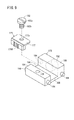
図5は、ハンドル本体20に設けられた機構ユニット133の斜視図である。図6は、機構ユニット133の分解斜視図である。図7は、機構ユニット133の一部断面平面図である。図8は、機構ユニット133の縦断面図である。機構ユニット133は、フレーム138と、フレーム138に回転可能に取り付けられた傾動用ホイール26と、フレーム138に内蔵されたブレーキ機構134と、フレーム138に組み込まれたブレーキ解除機構136とを有する。
FIG. 5 is a perspective view of the
機構ユニット133は、一部を除いて略全体がハンドル本体20内に配置される。フレーム138は、前後方向に貫通する貫通孔139を有する先端側構成部140と、先端側構成部140の後方に設けられ貫通孔139に連通する内部空間141を有する機構ボックス部142と、を備えた中空構造であり、先端側にシャフト18が挿入され固定される。フレーム138は、先端側構成部140、機構ボックス部142の上部壁、後部壁及び下部壁を構成するフレーム本体144と、機構ボックス部142の右側壁を構成する右側壁プレート146と、機構ボックス部142の左側壁を構成する左側壁プレート148とを有する。フレーム本体144に、右側壁プレート146と左側壁プレート148とが適宜の固定手段(図示例ではネジ150)で固定される。フレーム138の先端に設けられた円筒状突起部151が、筐体29の先端から突出する。
The
図8に示すように、フレーム138の上部には、軸受ハウジング152を介して軸受154が配置される。軸受ハウジング152は適宜の手段(図示例ではネジ156)によりフレーム138に固定され、当該軸受ハウジング152の内側に軸受154が装着される。軸受154により、傾動用ホイール26にネジ156で固定されたホイール軸部158が支持される。上記の構成により、フレーム138に対して傾動用ホイール26が回転可能に支持される。
As shown in FIG. 8, a
本実施形態では、傾動用ホイール26は、マニピュレータ10の上下方向の軸心を中心に回転可能である。また、本実施形態では、駆動プーリ130は、傾動用ホイール26と同軸に、ホイール軸部158を介して連結されているため、傾動用ホイール26と駆動プーリ130とは一体的に回転する。
In the present embodiment, the
図8に示すように、ホイール軸部158の、傾動用ホイール26が固定された側とは反対側の端部は、フレーム138に設けられた別の軸受160により支持される。ホイール軸部158の、軸受154により支持される箇所よりも下方には、上述したワイヤ132が巻き掛けられた駆動プーリ130が設けられる。この駆動プーリ130は、軸受154と軸受160との間に配置される。
As shown in FIG. 8, the end of the
図8に示すように、ワイヤ132は、駆動プーリ130の前方に配置された第1中間プーリ162及び第2中間プーリ164と、駆動プーリ130の後方に配置された第1テンション用プーリ166と第2テンション用プーリ168とに巻き掛けられる。
As shown in FIG. 8, the
第1中間プーリ162及び第2中間プーリ164は、駆動プーリ130の前方で、駆動プーリ130の回転軸線に対して直交する方向(マニピュレータ10の左右方向)の軸線を中心として、フレーム138に回転可能に支持される。第1中間プーリ162と第2中間プーリ164とは、駆動プーリ130の回転軸線に対して直交する方向に並設され、且つ互いに異なる高さに配置されている。
The first
本実施形態において、第1テンション用プーリ166と第2テンション用プーリ168は、左右方向(図8の紙面に対して垂直な方向)に互いに間隔をおいて配置され、駆動プーリ130の回転軸線と平行方向(マニピュレータ10の上下方向)な軸線を中心として回転可能に支持される。具体的には、第1テンション用プーリ166は、プーリ軸173によってプーリホルダ171の先端部に回転可能に支持される。第2テンション用プーリ168についても、第1テンション用プーリ166と同様に支持される。
In the present embodiment, the
第1テンション用プーリ166と第2テンション用プーリ168の各々に対応して、2つの調節ボルト170が設けられる。調節ボルト170のネジ棒170aは、フレーム138の後部壁138bに設けられた貫通孔172に後方から挿通され、当該後部壁138bに頭部170bが当接する。調節ボルト170を回転させると、螺合作用によってプーリホルダ171が前後方向に移動する。
Two
従って、一方の調節ボルト170を操作することにより、一方のプーリホルダ171に支持された第1テンション用プーリ166の位置を調整し、駆動プーリ130と従動プーリ90との間のワイヤ132の一方側部分に付与する張力を調整することができる。また、他方の調節ボルト170を操作することにより、他方のプーリホルダ171に支持された第2テンション用プーリ168の位置を調整し、駆動プーリ130と従動プーリ90との間のワイヤ132の他方側部分に付与する張力を調整することができる。
Therefore, by operating one
次に、ブレーキ機構134の構成を説明する。ブレーキ機構134は、傾動用ホイール26の回転に連動して回転するブレーキロータ174と、ブレーキロータ174の外周部に接触可能なブレーキシュー176と、ブレーキシュー176が取り付けられたスライド部材178と、スライド部材178を弾性的に付勢する弾性部材180とを有する。
Next, the configuration of the
本実施形態において、ブレーキロータ174は、傾動用ホイール26と先端動作部14との間の動力伝達経路上に設けられ、より具体的には、図8に示すように、ホイール軸部158において駆動プーリ130に隣接して設けられる。ブレーキロータ174は、円盤状であり、その外周部には、周方向に沿って第1ギヤ175Aが設けられる。
In the present embodiment, the
ブレーキシュー176は、ブレーキロータ174に対して進退動可能である。ブレーキシュー176の、ブレーキロータ174の外周部に対向する部分には、第1ギヤ175Aと噛合い可能な第2ギヤ175Bが設けられる。図9に示すように、第2ギヤ175Bは、ブレーキロータ174の外周部に適合する円弧状に延在する。ブレーキシュー176は、図示例ではL字状に形成された部品であり、固定手段(図示例ではボルト182)によって、スライド部材178に取り付けられる。
The
図10に示すように、ボルト182は、頭部182aと、雄ネジが形成されたネジ棒部182bと、頭部182aとネジ棒部182bとの間に形成された中間部182cとを有し、スライド部材178に設けられたネジ孔179にネジ棒部182bが螺合する。中間部182cの外径は、頭部182aの外径よりも小さく且つネジ棒部182bの外径よりも大きい。中間部182cがブレーキシュー176の取付プレート177に設けられた孔部177a内に配置され、取付プレート177がボルト182の頭部182aとスライド部材178との間に配置される。
As shown in FIG. 10, the
中間部182cの外径は、取付プレート177に設けられた孔部177aの内径よりも僅かに小さく、且つ中間部182cの軸線方向の厚さは、取付プレート177の厚さよりも僅かに厚い。このため、中間部182cの外周面と孔部177aを構成する内壁面との間、及び、取付プレート177の上面と頭部182aの下面との間には、それぞれ僅かな隙間が設けられる。このように、ブレーキシュー176はスライド部材178に対して若干の遊びを持って取り付けられている。換言すれば、ブレーキシュー176は、スライド部材178に対して、ボルト182の軸線を中心に僅かに揺動可能な状態でスライド部材178に取り付けられている。
The outer diameter of the intermediate portion 182c is slightly smaller than the inner diameter of the
図8に示すように、スライド部材178は、弾性部材180によってブレーキロータ174側に弾性的に常時押圧されるとともにブレーキロータ174に対して進退可能である。
As shown in FIG. 8, the
図9に示すように、スライド部材178は、前側を構成する前部184と、後ろ側を構成する後部186と、前部184と後部186の下部同士を繋ぐ中間構成部188とを有し、前部184の後面と後部186の前面と中間構成部188の上面とにより、スライド部材178の幅方向に延在する溝190が形成される。後部186の幅方向中央には、後方に開口する挿入穴192が形成される。この挿入穴192に、弾性部材180の一端側が挿入される。
As shown in FIG. 9, the
また、スライド部材178の左右両側面には、前後に間隔をおいた位置に、それぞれピン194が突出形成される。これらのピン194は、フレーム138の右側壁プレート146及び左側壁プレート148に形成された前後方向に延在する長孔196に、前後方向に摺動可能に挿入される。この構成より、スライド部材178は、フレーム138内で、ブレーキシュー176と一体的に、ブレーキロータ174に対して進退移動可能となっている。
In addition, pins 194 protrude from the left and right side surfaces of the
弾性部材180は、本実施形態では、コイルバネにより構成される。コイルバネに代えて、他の形態のバネ(板バネ、トーションスプリング等)や、ゴム体を用いてもよい。フレーム138のうち、スライド部材178を基準としてブレーキロータ174とは反対側を構成する後部壁138bには、弾性部材180が挿通可能な大きさの挿通孔198が設けられる。挿通孔198には、弾性部材180を押える押え部材200が装着されている。
In this embodiment, the
機構ユニット133の組立工程においては、図11に示すように、スライド部材178が内側に配置されたフレーム138の後方から挿通孔198を介して弾性部材180をフレーム138内に挿入し、その後、押え部材200を挿通孔198に装着することにより、押え部材200とスライド部材178との間に弾性部材180を圧縮状態で配置することができる。
In the assembly process of the
押え部材200は、弾性部材180の圧縮量を変更可能に挿通孔198に装着される。本実施形態において具体的には、挿通孔198を形成する内周部には雌ネジ部198aが形成され、押え部材200の外周部には雄ネジ部200aが形成される。これにより、押え部材200は挿通孔198に螺合可能となっている。押え部材200の捻じ込み具合に応じて、弾性部材180の圧縮量が変わり、これによりブレーキロータ174に対するブレーキシュー176の押し付け力を調整することができる。
The holding
次に、上記のように構成されたブレーキ機構134の作用を説明する。ブレーキ機構134では、弾性部材180の弾発力に基づいてブレーキシュー176がブレーキロータ174に押し付けられることにより制動力が発生する。すなわち、ブレーキシュー176がブレーキロータ174に押し付けられた状態では、ブレーキロータ174の回転が阻止され、傾動用ホイール26と先端動作部14との間における傾動動作に関する動力伝達機構の動きが阻止される。従って、マニピュレータ10の使用中、生体内に挿入されたグリッパ12で生体組織(臓器等)を押した場合でも、生体組織からの反力によってグリッパ12のシャフト18に対する角度が変わることが防止される。
Next, the operation of the
本実施形態の場合、弾性部材180の弾発力によりブレーキシュー176がブレーキロータ174に押し付けられた際、ブレーキロータ174に設けられた第1ギヤ175Aと、ブレーキシュー176に設けられた第2ギヤ175Bとが噛み合う。このため、ブレーキロータ174の外周部とブレーキシュー176とが共に平滑面である場合と比較して、ギヤ同士の噛み合いによる強い制動力が得られる。従って、弾性部材180の弾発力が小さくても、十分な制動力を得ることができることから、弾性部材180の弾発力に抗してブレーキを解除する際の操作力を効果的に低減することができる。従って、操作性に優れたマニピュレータ10を提供できる。
In the case of this embodiment, when the
また、本実施形態の場合、弾性部材180によってブレーキロータ174側に弾性的に押圧されるとともにブレーキロータ174に対して進退可能なスライド部材178を備え、ブレーキシュー176は、スライド部材178に固定された部品である。このように、ブレーキシュー176が、弾性部材180に押圧される部品に一体成型されたものではなく、別部品として構成されたスライド部材178に取り付けられた部品であるため、ブレーキシュー176の設計変更があった場合に、スライド部材178はそのままに、ブレーキシュー176のみを変更すればよいため、設計変更に柔軟に対応できる。
In the case of the present embodiment, a
更に、本実施形態の場合、第2ギヤ175Bは、ブレーキロータ174の外周部に適合する円弧状に延在し、ブレーキシュー176は、スライド部材178に対して僅かに揺動可能な状態でスライド部材178に取り付けられている。この構成により、ブレーキシュー176がブレーキロータ174に当接した際に、第1ギヤ175Aと第2ギヤ175Bとが周方向の所定範囲に亘って噛み合うようにブレーキシュー176が自動的に角度を変える。従って、ブレーキシュー176がブレーキロータ174に対して自動的に調心され、制動力を好適に発揮することができる。
Further, in the case of the present embodiment, the
本実施形態の場合、フレーム138の後部壁138bには、弾性部材180が挿通可能な大きさの挿通孔198が設けられ、当該挿通孔198に押え部材200が装着されているため、弾性部材180の組み込み及び取り外しを容易且つ迅速に行うことができる。また、挿通孔198に対する押え部材200の捻じ込みの深さを変えることで、弾性部材180の圧縮量を変え、ブレーキシュー176のブレーキロータ174に対する押し付け力を簡単に調整することができる。また、螺合構造であるため、押え部材200の位置の微調整が容易である。
In the case of this embodiment, the
一方、弾性部材180の弾発力に抗してブレーキシュー176をブレーキロータ174から離間させると、制動が解除される。すなわち、ブレーキシュー176がブレーキロータ174から離間した状態では、ブレーキロータ174の回転が阻止されないため、傾動用ホイール26とグリッパ12との間における傾動動作に関する動力伝達機構の動きが阻止されることがない。従って、傾動用ホイール26を回転操作することにより、その動力がグリッパ12に伝わり、グリッパ12の傾動動作が行われる。
On the other hand, when the
次に、ブレーキ解除機構136の構成を説明する。図7及び図8に示すように、ブレーキ解除機構136は、傾動用ホイール26に設けられた解除ボタン202(解除操作部)と、傾動用ホイール26の内側に配置され解除ボタン202の内方への移動に伴って押圧されるレバー機構204とを有する。解除ボタン202に対する内方への押圧操作に伴ってレバー機構204が動作することにより、ブレーキ機構134による制動が解除される。
Next, the configuration of the
解除ボタン202は、傾動用ホイール26の外周部に、当該外周部から径方向外方に突出する状態で、周方向に間隔をおいて複数設けられる。本実施形態では、傾動用ホイール26の外周部に、9つの解除ボタン202が等間隔に配置されている。
A plurality of
傾動用ホイール26は、ホイール軸部158が中心に固定された円盤部206と、円盤部206の外端縁に設けられ円盤部206よりも下方に突出した周縁部208とを有する。図8に示すように、周縁部208の内側には、環状凹部210が形成される。また、図6に示すように、周縁部208には、周方向に間隔をおいて複数の(図示例では9個)のボタン孔212が、傾動用ホイール26の径方向に貫通して設けられ、これらのボタン孔212の各々に、解除ボタン202が径方向に移動可能に配置される。組立工程において、解除ボタン202は、周縁部208の内側から挿入される。周縁部208には、周方向に沿って凸部214と凹部216が交互に複数ずつ形成され、複数の解除ボタン202は、複数の凹部216にそれぞれ設けられる。図示例の凹部216は円弧状である。
The
解除ボタン202の一端側には、互いに略反対方向に突出した係止片203が設けられる。係止片203は、解除ボタン202が傾動用ホイール26から外方に抜け出ることを防止する抜け止め部として機能する。周縁部208の内側には、解除ボタン202を外方に押すバックアップ部材218が設けられる。本実施形態において、バックアップ部材218は、自然状態で周縁部208の内径よりも大きい外径を有するようにリング状に湾曲した板バネであり、周縁部208の環状凹部210内に配置された状態では、両端部が重なって単一の輪を形成する。
One end of the
解除ボタン202は、それらの内側に配置されたバックアップ部材218により傾動用ホイール26の径方向外方に押される。これにより、解除ボタン202が傾動用ホイール26の周縁部208に形成されたボタン孔212から内方に脱落することが防止される。
The
図6、図7及び図12に示すように、本実施形態において、レバー機構204は、一対設けられる。以下、レバー機構204を互いに区別して説明する場合には、一方のレバー機構204を「第1レバー機構204A」と呼び、他方のレバー機構204を「第2レバー機構204B」と呼ぶ。
As shown in FIGS. 6, 7, and 12, in the present embodiment, a pair of
図12に示すように、各レバー機構204は、解除ボタン202の内方への移動に伴って傾動用ホイール26の内側で押圧されて回動するレバー220と、レバー220に設けられた軸部222a、222bと、軸部222a、222bを支点として動作するカム224a、224bとを有する。レバー220は傾動用ホイール26の周縁部208に沿って湾曲した形状を有し、その外周側には円弧状の被押圧部221が設けられる。被押圧部221の曲率半径は、周縁部208の内側に配置された状態のバックアップ部材218の内径と略同じか、僅かに小さい。レバー220は、被押圧部221が形成された角度範囲で、その外側に位置する解除ボタン202からの押圧を受けることができる。2つのレバー220は、同一形状で、左右対称に配置されている。
As shown in FIG. 12, each
図12に示すように、レバー220において、被押圧部221が形成された側とは反対側には基部220aが形成され、当該基部220aから軸部222a、222bが下方に突出するように結合されている。2つの軸部222a、222bは、フレーム138の上部壁に形成された2つの軸孔225にそれぞれ回転可能に支持されている。2つのレバー220に結合された軸部222a、222bは、互いに長さが異なっている。本実施形態では、第1レバー機構204Aの軸部222aが、第2レバー機構204Bの軸部222bよりも長い。
As shown in FIG. 12, in the
各軸部222a、222bの下端には、それぞれカム224a、224bが設けられる。図8に示すように、カム224a、224bは、フレーム138内に配置される。以下、2つのカム224a、224bを互いに区別して説明する場合には、第1レバー機構204Aに設けられたカム224aを「第1カム224a」と呼び、第2レバー機構204Bに設けられたカム224bを「第2カム224b」とよぶ。
図12に示すように、第1カム224aは第2カム224bよりも下方に配置され、2つのカム224a、224bは、互いに干渉しないように、平面視で互いに重なる位置に設けられる。また、第2カム224bは、その可動範囲内での動作時に第1レバー機構204Aの軸部222aと干渉しないように一部が凹んだ形状を有する。この構成により、第1レバー機構204Aと第2レバー機構204Bの軸部222a、222b同士を近接して配置しても、カム224a、224b同士が干渉することがない。従って、一対のレバー機構204を狭いスペースにコンパクトに配置することができる。
As shown in FIG. 12, the
図7に示すように、2つのカム224a、224bは、スライド部材178の後部186の前面の幅方向中央に当接した状態で、スライド部材178に設けられた溝190内に配置される。解除ボタン202が押圧操作されていない状態では、弾性部材180によって弾性的にブレーキロータ174側に向かって付勢されたスライド部材178が、2つのカム224a、224bを押圧する。カム224a、224bが受けた押圧力は、2つのレバー機構204を開く方向に作用する。
As shown in FIG. 7, the two
第1レバー機構204Aは、複数の解除ボタン202のうち一部の解除ボタン202(図7に示す状態では、解除ボタン202a、202b)に対する操作に基づいて作動し、第2レバー機構204Bは、複数の解除ボタン202のうち他の一部の解除ボタン202(図7に示す状態では、解除ボタン202c、202d)に対する操作に基づいて作動する。従って、一対のレバー機構204のいずれか一方が作動することによりブレーキ機構134による制動が解除されるようになっている。
The
次に、上記のように構成されたブレーキ解除機構136の作用を説明する。ブレーキ機構134による制動を解除するには、傾動用ホイール26に設けられた解除ボタン202を内方に押圧操作する。この場合、傾動用ホイール26のうち、ハンドル本体20の筐体29に設けられた開口27から露出した部分に触れることになるが、傾動用ホイール26の外周部の周方向に複数の解除ボタン202が設けられていることにより、操作者は確実に解除ボタン202を押圧することができる。そして、解除ボタン202を押圧すると、傾動用ホイール26の内側に配置されたバックアップ部材218を介して、2つのレバー機構204(具体的にはレバー220)の少なくとも一方が押圧される。
Next, the operation of the
この場合、例えば、ハンドル16の右側から露出した解除ボタン202を押圧操作した場合には、第1レバー機構204Aのレバー220が押圧されて、レバー220が軸部222aを中心として内方に回動する。ハンドル16の左側から露出した解除ボタン202を押圧操作した場合には、第2レバー機構204Bのレバー220が押圧されて、レバー220が軸部222bを中心として内方に回動する。また、ハンドル16の右側から露出した解除ボタン202と、ハンドル16の左側から露出した解除ボタン202の両方を内方に押圧操作した場合には、第1レバー機構204Aのレバー220と第2レバー機構204Bのレバー220が両方とも押されて内方に回動する。
In this case, for example, when the
第1レバー機構204Aと第2レバー機構204Bの一方又は両方の回動に伴って、カム224a、224bは、弾性部材180の弾性力に抗して、ブレーキロータ174とは反対方向(図示例でマニピュレータ10の後方)にスライド部材178を押圧し変位させる。スライド部材178の変位に伴って、スライド部材178に取り付けられたブレーキシュー176もスライド部材178と一体となって変位する。この場合、2つのカム224a、224bは、いずれもスライド部材178の幅方向中央に接触する。これにより、2つのレバー機構204のうち一方のみが回動した場合でも、カム224a、224bのいずれか一方がスライド部材178の幅方向中央を押すため、スライド部材178をスムーズに変位せることができる。
As one or both of the
スライド部材178の変位に伴って、ブレーキシュー176がブレーキロータ174から離間し、ブレーキロータ174が回転可能な状態となる。すなわち、ブレーキ機構134による制動が解除された状態となる。従って、解除ボタン202を押圧した状態で、傾動用ホイール26に回転方向の操作力を加えることで、傾動用ホイール26を回転させ、グリッパ12を傾動動作させることができる。この場合、解除ボタン202は、傾動用ホイール26と一体的に回転するため、解除ボタン202を内方に押した状態を維持しながら、傾動用ホイール26の回転操作を簡単に行うことができる。
With the displacement of the
このように、ブレーキ解除機構136によれば、グリッパ12を傾動動作させるための傾動用ホイール26に、ブレーキを解除するための解除ボタン202が設けられるため、マニピュレータ10の操作者は、傾動用ホイール26を操作する手で解除ボタン202に簡単に触れることができる。これにより、ブレーキ機構134による制動を片手で簡単且つ迅速に解除することができる。すなわち、ブレーキの解除操作と傾動用ホイール26の回転操作を片手で簡単且つ確実に行うことができる。
Thus, according to the
また、解除ボタン202に対する操作に伴って押圧されるレバー220が、傾動用ホイール26の内側に配置されるので、ブレーキ解除機構136をコンパクトに構成でき、ブレーキ機構134が組み込まれるマニピュレータ10の小型軽量化に寄与できる。
In addition, since the
本実施形態の場合、レバー機構204は、解除ボタン202の内方への移動に伴って傾動用ホイール26の内側で押圧されて回動するレバー220と、レバー220に設けられた軸部222a、222bと、軸部222a、222bを支点として動作するカム224a、224bとを有し、解除ボタン202に対する操作に伴って、カム224a、224bがブレーキシュー176をブレーキロータ174から離間させるように動作することにより、制動が解除される。このように構成されるため、レバー機構204のレバー比を適切に設定することにより、低い操作力でブレーキを解除できる。
In the case of this embodiment, the
本実施形態の場合、2つのレバー機構204が設けられ、どちらか一方のレバー機構204が作動することで、制動が解除されるので、ブレーキ解除操作をより簡単且つ確実に行うことができる。
In the case of this embodiment, two
また、本実施形態の場合、解除ボタン202は、傾動用ホイール26の外周部に、内外方向に変位可能に設けられる。この構成によれば、解除ボタン202を内方に押圧することでブレーキを解除し、且つその状態で傾動用ホイール26の回転操作を行うことができるため、ブレーキ解除操作とその後の回転操作を淀みなくスムーズに行うことができる。
In the case of the present embodiment, the
更に、本実施形態の場合、解除ボタン202を外方に押すバックアップ部材218が傾動用ホイール26の内側に設けられるため、レバー220に対応しない位置にある解除ボタン202が傾動用ホイール26から脱落することがない。
Further, in the present embodiment, since the
本実施形態の場合、傾動用ホイール26の外周部に、周方向の異なる位置に解除ボタン202が複数設けられる。この構成によれば、解除ボタン202が1つだけではなく複数設けられるため、使用者が把持し易い解除ボタン202を選択して押圧するだけで簡単にブレーキ解除操作を行うことができる。
In the case of this embodiment, a plurality of
本実施形態の場合、傾動用ホイール26の外周部には、周方向に沿って凸部214と凹部216が交互に複数ずつ形成され、複数の解除ボタン202は複数の凹部216にそれぞれ設けられる。この構成によれば、不意に傾動用ホイール26に触れただけでは解除ボタン202が押圧されにくい配置となっているため、意図しないブレーキ解除の発生を効果的に抑制できる。
In the case of this embodiment, a plurality of
上記において、本発明について好適な実施形態を挙げて説明したが、本発明は前記実施形態に限定されるものではなく、本発明の要旨を逸脱しない範囲において、種々の改変が可能なことは言うまでもない。 In the above description, the present invention has been described with reference to preferred embodiments. However, the present invention is not limited to the above-described embodiments, and various modifications can be made without departing from the scope of the present invention. Yes.
10…医療用マニピュレータ 12…グリッパ
14…先端動作部 26…傾動用ホイール
134…ブレーキ機構 136…ブレーキ解除機構
138…フレーム 174…ブレーキロータ
175A…第1ギヤ 175B…第2ギヤ
176…ブレーキシュー 178…スライド部材
180…弾性部材 200…押え部材
202…解除ボタン 204…レバー機構
204A…第1レバー機構 204B…第2レバー機構
218…バックアップ部材 220…レバー
222a、222b…軸部 224a…カム(第1カム)
224b…カム(第2カム)
DESCRIPTION OF
224b ... Cam (second cam)
Claims (4)
前記操作部の回転に連動して回転するブレーキロータと、
前記ブレーキロータに対して進退動可能であり、前記ブレーキロータの外周部に接触可能なブレーキシューと、を備え、
弾性部材の弾発力に基づいて前記ブレーキシューを前記ブレーキロータに押し付けることにより制動力が発生し、
前記弾発力に抗して前記ブレーキシューを前記ブレーキロータから離間させることにより制動が解除され、
前記ブレーキロータの前記外周部には、周方向に沿って第1ギヤが設けられ、
前記ブレーキシューの、前記ブレーキロータの前記外周部に対向する部分には、前記第1ギヤと噛合い可能な第2ギヤが設けられ、
前記ブレーキ機構は、さらに、前記弾性部材によって前記ブレーキロータ側に弾性的に押圧されるとともに前記ブレーキロータに対して進退動可能なスライド部材を備え、
前記ブレーキシューは、前記スライド部材に取り付けられた部品であり、
前記第2ギヤは、前記ブレーキロータの前記外周部に適合する円弧状に延在し、
前記ブレーキシューは、前記スライド部材に対して僅かに揺動可能な状態で前記スライド部材に取り付けられている、
ことを特徴とするブレーキ機構。 A brake mechanism that mechanically transmits an input operation to the operation unit and restricts the movement of the mechanism in which the operation unit interlocks,
A brake rotor that rotates in conjunction with the rotation of the operation unit;
A brake shoe capable of moving forward and backward with respect to the brake rotor and capable of contacting an outer peripheral portion of the brake rotor;
A braking force is generated by pressing the brake shoe against the brake rotor based on the elastic force of the elastic member,
Brake is released by separating the brake shoe from the brake rotor against the elastic force,
The outer periphery of the brake rotor is provided with a first gear along the circumferential direction,
Wherein the brake shoe, wherein the portion opposed to the outer peripheral portion of the brake rotor, the first second gear capable have gear meshing is provided et al is,
The brake mechanism further includes a slide member that is elastically pressed toward the brake rotor side by the elastic member and can move forward and backward with respect to the brake rotor,
The brake shoe is a component attached to the slide member,
The second gear extends in an arc shape that fits the outer periphery of the brake rotor,
The brake shoe is attached to the slide member in a state in which the brake shoe is slightly swingable with respect to the slide member.
Brake mechanism characterized by that.
前記ブレーキロータ、前記ブレーキシュー及び前記スライド部材は、フレーム内に配置され、
前記フレームのうち、前記スライド部材を基準として前記ブレーキロータとは反対側を構成する壁部には、前記弾性部材が挿通可能な大きさの挿通孔が設けられ、
前記挿通孔には、前記弾性部材を押える押え部材が装着されている、
ことを特徴とするブレーキ機構。 The brake mechanism according to claim 1 , wherein
The brake rotor, the brake shoe and the slide member are arranged in a frame,
An insertion hole of a size that allows the elastic member to be inserted is provided in a wall portion that constitutes the opposite side of the brake rotor with respect to the slide member of the frame,
A presser member that holds the elastic member is attached to the insertion hole.
Brake mechanism characterized by that.
前記押え部材は、前記弾性部材の圧縮量を変更可能に前記挿通孔に装着される、
ことを特徴とするブレーキ機構。 The brake mechanism according to claim 2 ,
The pressing member is attached to the insertion hole so that the compression amount of the elastic member can be changed.
Brake mechanism characterized by that.
請求項1〜3のいずれか1項に記載のブレーキ機構を備え、
前記ブレーキロータは、前記傾動操作部の回転に連動して回転するものであり、
前記弾性部材の弾発力に基づいて前記ブレーキシューを前記ブレーキロータに押し付けることにより、前記ブレーキロータの回転が阻止され、前記シャフトに対する前記先端動作部の角度が固定される、
ことを特徴とする医療用マニピュレータ。
A tip operating portion that can tilt with respect to the shaft is provided at the tip of the shaft extending from the handle, and an input operation to the tilt operating portion provided on the handle is mechanically transmitted to tilt the tip operating portion. A medical manipulator configured to:
A brake mechanism according to any one of claims 1 to 3 , comprising:
The brake rotor rotates in conjunction with the rotation of the tilt operation unit,
By pressing the brake shoe against the brake rotor based on the elastic force of the elastic member, the rotation of the brake rotor is prevented, and the angle of the tip operating portion with respect to the shaft is fixed.
A medical manipulator characterized by that.
Priority Applications (4)
| Application Number | Priority Date | Filing Date | Title |
|---|---|---|---|
| JP2012212061A JP6042678B2 (en) | 2012-09-26 | 2012-09-26 | Brake mechanism and medical manipulator having the same |
| PCT/JP2013/075632 WO2014050784A1 (en) | 2012-09-26 | 2013-09-24 | Brake mechanism and medical manipulator provided with same |
| EP13842394.2A EP2901956B1 (en) | 2012-09-26 | 2013-09-24 | Brake mechanism and medical manipulator provided with same |
| US14/669,866 US9999434B2 (en) | 2012-09-26 | 2015-03-26 | Brake mechanism and medical manipulator provided with same |
Applications Claiming Priority (1)
| Application Number | Priority Date | Filing Date | Title |
|---|---|---|---|
| JP2012212061A JP6042678B2 (en) | 2012-09-26 | 2012-09-26 | Brake mechanism and medical manipulator having the same |
Publications (3)
| Publication Number | Publication Date |
|---|---|
| JP2014064755A JP2014064755A (en) | 2014-04-17 |
| JP2014064755A5 JP2014064755A5 (en) | 2015-10-08 |
| JP6042678B2 true JP6042678B2 (en) | 2016-12-14 |
Family
ID=50388185
Family Applications (1)
| Application Number | Title | Priority Date | Filing Date |
|---|---|---|---|
| JP2012212061A Active JP6042678B2 (en) | 2012-09-26 | 2012-09-26 | Brake mechanism and medical manipulator having the same |
Country Status (4)
| Country | Link |
|---|---|
| US (1) | US9999434B2 (en) |
| EP (1) | EP2901956B1 (en) |
| JP (1) | JP6042678B2 (en) |
| WO (1) | WO2014050784A1 (en) |
Families Citing this family (8)
| Publication number | Priority date | Publication date | Assignee | Title |
|---|---|---|---|---|
| US20160038720A1 (en) * | 2014-08-05 | 2016-02-11 | Jeffrey Thomas Loh | Swivel tipped guidewire and related methods |
| EP3326764A4 (en) | 2015-07-17 | 2019-03-13 | Olympus Corporation | Manipulator |
| DE102015115559A1 (en) * | 2015-09-15 | 2017-03-16 | Karl Storz Gmbh & Co. Kg | Manipulation system and handling device for surgical instruments |
| JP6673140B2 (en) * | 2016-10-20 | 2020-03-25 | 株式会社デンソー | Arm device |
| WO2019087384A1 (en) | 2017-11-06 | 2019-05-09 | オリンパス株式会社 | Treatment tool |
| JP6809720B2 (en) * | 2019-03-13 | 2021-01-06 | リバーフィールド株式会社 | Surgical tool |
| DE102019125957B4 (en) * | 2019-09-26 | 2021-04-29 | Franka Emika Gmbh | Braking device for a robot manipulator |
| CN114684582B (en) * | 2020-12-30 | 2024-03-26 | 天津三环乐喜新材料有限公司 | Turning device, feeding and turning system and method |
Family Cites Families (15)
| Publication number | Priority date | Publication date | Assignee | Title |
|---|---|---|---|---|
| US5816901A (en) * | 1993-04-09 | 1998-10-06 | Sirany; Dallas R. | Method of resurfacing a vehicles's braking rotors and drums |
| US5823066A (en) * | 1996-05-13 | 1998-10-20 | Ethicon Endo-Surgery, Inc. | Articulation transmission mechanism for surgical instruments |
| US5830231A (en) * | 1997-03-19 | 1998-11-03 | Geiges, Jr.; John J. | Handle and actuating mechanism for surgical instruments |
| JP4135875B2 (en) | 2002-06-05 | 2008-08-20 | Hoya株式会社 | Endoscope additional treatment tool guide |
| WO2004086987A1 (en) * | 2003-03-26 | 2004-10-14 | Tyco Healthcare Group, Lp | Energy stored in spring with controlled release |
| JP4391762B2 (en) | 2003-05-08 | 2009-12-24 | オリンパス株式会社 | Surgical instrument |
| US8764765B2 (en) | 2003-09-23 | 2014-07-01 | Covidien Lp | Laparoscopic instrument and related surgical method |
| JP2006326148A (en) * | 2005-05-30 | 2006-12-07 | Kanazawa Inst Of Technology | Surgical treatment tool |
| US8579176B2 (en) * | 2005-07-26 | 2013-11-12 | Ethicon Endo-Surgery, Inc. | Surgical stapling and cutting device and method for using the device |
| US8409244B2 (en) * | 2007-04-16 | 2013-04-02 | Intuitive Surgical Operations, Inc. | Tool with end effector force limiter |
| JP5409368B2 (en) * | 2006-10-05 | 2014-02-05 | コヴィディエン リミテッド パートナーシップ | Flexible endoscopic suturing device |
| US20090198272A1 (en) * | 2008-02-06 | 2009-08-06 | Lawrence Kerver | Method and apparatus for articulating the wrist of a laparoscopic grasping instrument |
| WO2010104755A1 (en) * | 2009-03-05 | 2010-09-16 | Tyco Healthcare Group Lp | Endoscopic vessel sealer and divider having a flexible articulating shaft |
| US8132706B2 (en) * | 2009-06-05 | 2012-03-13 | Tyco Healthcare Group Lp | Surgical stapling apparatus having articulation mechanism |
| WO2012006306A2 (en) * | 2010-07-08 | 2012-01-12 | Ethicon Endo-Surgery, Inc. | Surgical instrument comprising an articulatable end effector |
-
2012
- 2012-09-26 JP JP2012212061A patent/JP6042678B2/en active Active
-
2013
- 2013-09-24 WO PCT/JP2013/075632 patent/WO2014050784A1/en active Application Filing
- 2013-09-24 EP EP13842394.2A patent/EP2901956B1/en active Active
-
2015
- 2015-03-26 US US14/669,866 patent/US9999434B2/en active Active
Also Published As
| Publication number | Publication date |
|---|---|
| US9999434B2 (en) | 2018-06-19 |
| EP2901956A1 (en) | 2015-08-05 |
| EP2901956A4 (en) | 2016-05-25 |
| JP2014064755A (en) | 2014-04-17 |
| WO2014050784A1 (en) | 2014-04-03 |
| EP2901956B1 (en) | 2017-05-17 |
| US20150196313A1 (en) | 2015-07-16 |
Similar Documents
| Publication | Publication Date | Title |
|---|---|---|
| JP6082553B2 (en) | Brake release mechanism and medical manipulator having the same | |
| JP6042678B2 (en) | Brake mechanism and medical manipulator having the same | |
| JP5921943B2 (en) | Medical manipulator | |
| EP3345552B1 (en) | Natural channel-based microsurgical device | |
| JP4755047B2 (en) | Working mechanism and manipulator | |
| JP5395282B2 (en) | Endoscope | |
| WO2013002063A1 (en) | Medical manipulator | |
| JPWO2013073523A1 (en) | Medical equipment | |
| JP2002224016A (en) | Endoscope | |
| JP2010227438A (en) | Method of manufacturing medical instrument, and medical instrument | |
| JP2004154164A (en) | Multi-degree-of-freedom type treating instrument | |
| JP6042629B2 (en) | Medical manipulator | |
| JP4454956B2 (en) | Endoscope | |
| JP6858954B2 (en) | Endoscope system | |
| JP2019509090A (en) | Endoscopic instrument | |
| JP6053102B2 (en) | Medical manipulator | |
| JP5096202B2 (en) | Endoscope system | |
| JP5909142B2 (en) | Medical manipulator | |
| JP5990024B2 (en) | Medical manipulator | |
| JP2023041714A (en) | Endoscopic instrument | |
| JP2010253205A (en) | Manipulator | |
| JP4598787B2 (en) | Surgical tools | |
| WO2018179042A1 (en) | Surgery device | |
| CN116568198A (en) | Endoscopic treatment tool, endoscopic device, and treatment method | |
| JP2005230333A (en) | Instrument for endoscope |
Legal Events
| Date | Code | Title | Description |
|---|---|---|---|
| A711 | Notification of change in applicant |
Free format text: JAPANESE INTERMEDIATE CODE: A711 Effective date: 20140324 |
|
| A711 | Notification of change in applicant |
Free format text: JAPANESE INTERMEDIATE CODE: A711 Effective date: 20140325 |
|
| A521 | Request for written amendment filed |
Free format text: JAPANESE INTERMEDIATE CODE: A523 Effective date: 20150824 |
|
| A621 | Written request for application examination |
Free format text: JAPANESE INTERMEDIATE CODE: A621 Effective date: 20150824 |
|
| A131 | Notification of reasons for refusal |
Free format text: JAPANESE INTERMEDIATE CODE: A131 Effective date: 20160712 |
|
| A521 | Request for written amendment filed |
Free format text: JAPANESE INTERMEDIATE CODE: A523 Effective date: 20161005 |
|
| TRDD | Decision of grant or rejection written | ||
| A01 | Written decision to grant a patent or to grant a registration (utility model) |
Free format text: JAPANESE INTERMEDIATE CODE: A01 Effective date: 20161025 |
|
| A61 | First payment of annual fees (during grant procedure) |
Free format text: JAPANESE INTERMEDIATE CODE: A61 Effective date: 20161110 |
|
| R150 | Certificate of patent or registration of utility model |
Ref document number: 6042678 Country of ref document: JP Free format text: JAPANESE INTERMEDIATE CODE: R150 |
|
| S531 | Written request for registration of change of domicile |
Free format text: JAPANESE INTERMEDIATE CODE: R313531 |
|
| S533 | Written request for registration of change of name |
Free format text: JAPANESE INTERMEDIATE CODE: R313533 |
|
| R350 | Written notification of registration of transfer |
Free format text: JAPANESE INTERMEDIATE CODE: R350 |
|
| R250 | Receipt of annual fees |
Free format text: JAPANESE INTERMEDIATE CODE: R250 |
|
| R250 | Receipt of annual fees |
Free format text: JAPANESE INTERMEDIATE CODE: R250 |
|
| R250 | Receipt of annual fees |
Free format text: JAPANESE INTERMEDIATE CODE: R250 |
|
| R250 | Receipt of annual fees |
Free format text: JAPANESE INTERMEDIATE CODE: R250 |
|
| R250 | Receipt of annual fees |
Free format text: JAPANESE INTERMEDIATE CODE: R250 |