JP6029324B2 - Construction machine that automatically adjusts fan rotation speed - Google Patents
Construction machine that automatically adjusts fan rotation speed Download PDFInfo
- Publication number
- JP6029324B2 JP6029324B2 JP2012123421A JP2012123421A JP6029324B2 JP 6029324 B2 JP6029324 B2 JP 6029324B2 JP 2012123421 A JP2012123421 A JP 2012123421A JP 2012123421 A JP2012123421 A JP 2012123421A JP 6029324 B2 JP6029324 B2 JP 6029324B2
- Authority
- JP
- Japan
- Prior art keywords
- controller
- fan
- viscous coupling
- rotational speed
- temperature
- Prior art date
- Legal status (The legal status is an assumption and is not a legal conclusion. Google has not performed a legal analysis and makes no representation as to the accuracy of the status listed.)
- Active
Links
Images


Classifications
-
- F—MECHANICAL ENGINEERING; LIGHTING; HEATING; WEAPONS; BLASTING
- F01—MACHINES OR ENGINES IN GENERAL; ENGINE PLANTS IN GENERAL; STEAM ENGINES
- F01P—COOLING OF MACHINES OR ENGINES IN GENERAL; COOLING OF INTERNAL-COMBUSTION ENGINES
- F01P7/00—Controlling of coolant flow
- F01P7/02—Controlling of coolant flow the coolant being cooling-air
- F01P7/04—Controlling of coolant flow the coolant being cooling-air by varying pump speed, e.g. by changing pump-drive gear ratio
- F01P7/042—Controlling of coolant flow the coolant being cooling-air by varying pump speed, e.g. by changing pump-drive gear ratio using fluid couplings
Description
本発明は、請求項1の導入部分に記載の自動的にファン回転速度を調節する建設機械に関すると共に、請求項15に記載のファンを駆動する方法に関する。
The invention relates to a construction machine for automatically adjusting the fan rotational speed according to the introduction part of claim 1 and to a method for driving a fan according to
建設機械、特に道路舗装機やフィーダでは、ディーゼルエンジンが駆動モータとして使用されている。ディーゼルエンジンとディーゼルエンジンで駆動する装置の両方共、エンジンの効率に応じた排熱があり、冷却装置によって放熱する必要がある。現在の道路舗装機では、要求温度までの冷却は、熱交換器を介して、様々な冷媒、例えば、冷却水、給気及び/又は作動油等によって行われている。確実に空気流を熱交換器に通すために、ファンが冷却システムの要素となっている。ファンが常時ディーゼルエンジンの出力回転速度に対応するファン回転速度をとるように、ファンをディーゼルエンジンに固定的に接続することが知られている。 In construction machines, particularly road pavers and feeders, diesel engines are used as drive motors. Both the diesel engine and the device driven by the diesel engine have exhaust heat corresponding to the efficiency of the engine, and it is necessary to dissipate heat by the cooling device. In current road pavers, cooling to a required temperature is performed by various refrigerants such as cooling water, supply air and / or hydraulic oil through a heat exchanger. A fan is an element of the cooling system to ensure that the airflow passes through the heat exchanger. It is known that the fan is fixedly connected to the diesel engine so that the fan always takes a fan rotation speed corresponding to the output rotation speed of the diesel engine.
また、道路舗装機の場合、実際には油圧で駆動するファンで得られる冷却用空気供給を必要に応じて使用することが知られている。しかしながら、それには、ファン駆動部における油圧ロスを許容しければならないという短所がある。また、油圧ファン駆動部の効率を最適化すると、費用が著しく増える。これは、油圧ファン駆動部の効率を最適化することは、経済的な定流量ポンプを活用できなくなることを意味するからである。 In the case of a road paving machine, it is known that a cooling air supply obtained by a hydraulically driven fan is actually used as needed. However, this has the disadvantage that hydraulic loss in the fan drive must be tolerated. Also, optimizing the efficiency of the hydraulic fan drive increases the cost significantly. This is because optimizing the efficiency of the hydraulic fan drive means that an economical constant flow pump cannot be used.
本発明の基礎は、冷却用空気流を、建設機械の様々な動作状況に自動的に対応させるのに用いる、自動的にファン回転速度を調節する建設機械を作製するという目的から成り、同目的のために、経済的且つ低騒音の技術手段を使用する。同じく、冷却用空気流を自動的に調節する方法を構築することも、本発明の目的である。 The basis of the present invention consists of the purpose of creating a construction machine that automatically adjusts the fan rotation speed, which is used to automatically adapt the cooling air flow to various operating conditions of the construction machine. For this purpose, economical and low-noise technical means are used. It is also an object of the present invention to build a method for automatically adjusting the cooling air flow.
そうした目的を、請求項1の技術的特徴を用いて、及び請求項15の技術的特徴を用いて解決する。
This object is solved with the technical features of claim 1 and with the technical features of
本発明の改良した更なる発展形については、従属クレームの技術的特徴によって与えられるものとする。 Further refinements of the invention shall be given by the technical features of the dependent claims.
本発明によれば、建設機械を、特に道路舗装機又はフィーダとする。道路舗装機は、駆動部と、冷却用空気流を生成するために提供されるファンを有する冷却システムを含む。本発明によれば、冷却システムは、調節可能なビスカスカップリングを更に含み、該ビスカスカップリングを、入力側で駆動部に接続し、出力側で冷却システムのファンに接続する。ビスカスカップリングにより、駆動部の駆動トルクを、出力側にあるファンに伝達し、その結果該ファンが冷却用空気流を生成する。 According to the invention, the construction machine is in particular a road paving machine or a feeder. The road paving machine includes a cooling system having a drive and a fan provided to generate a cooling airflow. According to the invention, the cooling system further comprises an adjustable viscous coupling, which is connected to the drive on the input side and to the fan of the cooling system on the output side. By the viscous coupling, the driving torque of the driving unit is transmitted to the fan on the output side, and as a result, the fan generates a cooling air flow.
本発明の場合、調節可能なビスカスカップリングは、カップリング内の異なる油量によって異なるトルクを伝達する可能性を提供する。ビスカスカップリングは、互いに対向して配置された2円板から成り、1枚目の円板で駆動部を形成し、2枚目の円板を出力側とする。トルクを伝達する場合、油の動粘度によって出力側を入力側と共に移動させるように、カップリング空間を油で充填しなければならない。この機能のために、ビスカスカップリングの出力側の回転速度は、常に入力側の回転速度より低くなる。より低い出力回転速度を実現しようとするならば、より少ない油量で実行可能になる。ビスカスカップリング内で永久的に油を循環させることによって、カップリングの油量を、給油弁や一定の排油流量の助けを借りて規定できるが、この循環は、特定の最低回転速度になるまで開始しない。ビスカスカップリングの出力側で低回転速度の必要がある場合、油制御弁を閉弁して、カップリング内に依然として存在する油を、遠心力によって油出孔を通して油空間の外に転位させる。ビスカスカップリングに油が全くない場合は、最低回転速度、つまりスリップ回転速度が確立される。出力側の目標回転速度を上げる場合、油出口から排出できる油より多くの油を、油制御弁を通して供給しなければならないが、その結果回転速度は高くなる。ビスカスカップリングを完全に油で満した場合、上流で回転速度を調節するには、出力回転速度が目標回転速度に到達するまでにかなり長い時間が必要となる。駆動回転速度が低いほど、この時間は長くなる。特に、アイドリング中には、ビスカスカップリング内部での油循環は大幅に減少し、そのため回転速度の調節が、この動作点では不可能となる。 In the case of the present invention, the adjustable viscous coupling offers the possibility of transmitting different torques with different amounts of oil in the coupling. The viscous coupling is composed of two discs arranged so as to face each other, and a drive unit is formed by the first disc, and the second disc is used as the output side. When transmitting torque, the coupling space must be filled with oil so that the output side moves with the input side due to the kinematic viscosity of the oil. Because of this function, the rotational speed on the output side of the viscous coupling is always lower than the rotational speed on the input side. If a lower output rotational speed is to be realized, it becomes feasible with a smaller amount of oil. By permanently circulating the oil in the viscous coupling, the amount of oil in the coupling can be defined with the aid of an oil supply valve and a constant oil flow rate, but this circulation will be at a certain minimum rotational speed Do not start until. When a low rotational speed is required on the output side of the viscous coupling, the oil control valve is closed and the oil still present in the coupling is transferred out of the oil space through the oil outlet by centrifugal force. If there is no oil in the viscous coupling, the minimum rotational speed, that is, the slip rotational speed is established. When the target rotational speed on the output side is increased, more oil than can be discharged from the oil outlet has to be supplied through the oil control valve. As a result, the rotational speed is increased. When the viscous coupling is completely filled with oil, it takes a considerably long time for the output rotational speed to reach the target rotational speed in order to adjust the rotational speed upstream. The lower the drive rotation speed, the longer this time. In particular, during idling, the oil circulation inside the viscous coupling is greatly reduced, so that the rotational speed cannot be adjusted at this operating point.
本発明の場合、調節可能なビスカスカップリングにより、確実に、アクチュエータ部とファンとの間を低騒音で接続できる。これにより、建設機械付近にいる者の作業条件が改善され、互いに簡単に対話ができるようになる。 In the case of the present invention, the adjustable viscous coupling can reliably connect the actuator unit and the fan with low noise. This improves the working conditions of those near the construction machine and makes it easy to interact with each other.
調節可能なビスカスカップリングにより、状況に応じてファンを起動可能になり、ビスカスカップリングの油量に応じて、必要な回転速度をファンに関して調整でき、該回転速度を駆動部の回転速度とは独立したものとすることができる。本発明の場合、ビスカスカップリングにより、駆動部とファンとの間のトルク伝達を最小にできる、或いは完全に防止でき、その結果ファンは最低回転速度で動作する又は停止する点も、有利である。これは、氷点付近の温度で建設機械を始動させる際に、最適温度に出来る限り速く到達させるのに、特に有用である。 Adjustable viscous coupling makes it possible to start the fan according to the situation, the required rotational speed can be adjusted for the fan according to the amount of oil in the viscous coupling, and the rotational speed is the rotational speed of the drive unit It can be independent. In the case of the present invention, it is also advantageous that the viscous coupling can minimize or completely prevent torque transmission between the drive and the fan, so that the fan operates or stops at the lowest rotational speed. . This is particularly useful for reaching the optimum temperature as quickly as possible when starting the construction machine at temperatures near freezing.
また、ビスカスカップリングによって、ファンを駆動部に固定的に接続した場合よりも燃料を節約してファンを駆動する方法が可能となる。つまり、設定するファン回転速度を、駆動部の駆動回転速度より低くしても、通常のモータ負荷に対しては、その低いファン回転速度で十分となる。 Further, the viscous coupling enables a method of driving the fan while saving fuel as compared with the case where the fan is fixedly connected to the drive unit. That is, even if the set fan rotation speed is lower than the drive rotation speed of the drive unit, the low fan rotation speed is sufficient for a normal motor load.
また同様に、ビスカスカップリングには、排熱が、油圧駆動式ファンより少なくなり、その結果ビスカスカップリングによって全体の効率が向上するという技術的利点がある。 Similarly, the viscous coupling has the technical advantage that the exhaust heat is less than that of the hydraulically driven fan, and as a result, the overall efficiency is improved by the viscous coupling.
それに加えて、ビスカスカップリングを、駆動部のトルクを穏やかに、つまり緩やかに、急激ではなくファンに伝達できるように、調節できる。その結果、長期間に亘り、ファンの適切な機能を、建設機械に対して維持できる。 In addition, the viscous coupling can be adjusted so that the torque of the drive can be transmitted gently, i.e. gently, to the fan rather than suddenly. As a result, the proper function of the fan can be maintained for the construction machine over a long period of time.
好ましくは、冷却システムは、ビスカスカップリング及び/又は駆動部に接続するコントローラを含む。特定の油量に、コントローラによってビスカスカップリング内で調整できる。油量に応じて、ビスカスカップリングによって、駆動トルクを特定の出力トルクに変換できる。 Preferably, the cooling system includes a controller coupled to the viscous coupling and / or drive. A specific oil quantity can be adjusted in the viscous coupling by the controller. Depending on the amount of oil, the driving torque can be converted into a specific output torque by viscous coupling.
ビスカスカップリングを、ある一定の回転速度又はトルク比が駆動部とファンとの間で生じるように、コントローラによって調整できる。 The viscous coupling can be adjusted by the controller so that a certain rotational speed or torque ratio occurs between the drive and the fan.
本発明の更なる実施形態では、コントローラを、冷却システムの少なくとも1つの動作温度を記録するように、構成する。好ましくは、これを、給気温度、作動液温度及び/又は冷却水温度といった動作温度とする。このようにして、コントローラにより、リアルタイムで冷却システムの動作状態を監視できる。更にまた、発生する可能性がある冷却システムの極端な温度を抑制するために、確実にコントローラによりビスカスカップリングをタイミング良く駆動させる。 In a further embodiment of the invention, the controller is configured to record at least one operating temperature of the cooling system. Preferably, this is an operating temperature such as a supply air temperature, a hydraulic fluid temperature and / or a cooling water temperature. In this way, the controller can monitor the operating state of the cooling system in real time. Furthermore, in order to suppress the extreme temperature of the cooling system that may occur, the viscous coupling is reliably driven by the controller in a timely manner.
冷却システムの動作温度の他にも、駆動部の少なくとも1つの動作温度、好ましくは吸気温度及び/又は周囲温度を記録するように、コントローラを構成する。そうすることで、特に夏に、新たに敷設した舗道によって更に発生する熱のために建設機械付近で極端な温度が生じた際に、コントローラが同様にファン回転速度調節に関しても周囲状況を踏まえるという利点を提供できる。 In addition to the operating temperature of the cooling system, the controller is configured to record at least one operating temperature of the drive, preferably the intake air temperature and / or the ambient temperature. By doing so, especially in the summer, when extreme temperatures occur near the construction machine due to the additional heat generated by the newly laid pavement, the controller will also take into account the ambient conditions for adjusting the fan speed Can provide benefits.
また、コントローラを、冷却システムの動作温度の及び/又は駆動部の動作温度の下限温度及び/又は上限温度を記録するように構成し、それによりコントローラが動作温度に関して過熱及び/又は過冷却に対して迅速に反応可能にすると、有用である。 The controller is also configured to record a lower temperature limit and / or an upper temperature limit of the operating temperature of the cooling system and / or the operating temperature of the drive, so that the controller is free from overheating and / or overcooling with respect to the operating temperature. It is useful to be able to react quickly.
更なる実施形態では、ファン回転速度が駆動部の駆動回転速度に実質的に対応するように、ビスカスカップリングを調節するように、コントローラを構成する。このようにして、最大冷却空気流を提供できる。これは、冷却システムの及び/又は駆動部の監視動作温度の1つが、上限温度に達した、又は上限温度を超えたかをコントローラが決定する場合に、好ましい。 In a further embodiment, the controller is configured to adjust the viscous coupling such that the fan rotational speed substantially corresponds to the drive rotational speed of the drive. In this way, a maximum cooling air flow can be provided. This is preferred when the controller determines whether one of the monitoring operating temperatures of the cooling system and / or the drive has reached or exceeded the upper limit temperature.
本発明の更に有利な実施形態では、駆動部の定格回転速度及び/又は負荷係数を記録するために、コントローラを駆動部に接続する。そうすることで、コントローラは常に駆動部の現在の動作状態についての情報を得られ、コントローラはそれに応じてビスカスカップリングを駆動できる。 In a further advantageous embodiment of the invention, a controller is connected to the drive for recording the rated rotational speed and / or load factor of the drive. By doing so, the controller is always informed about the current operating state of the drive, and the controller can drive the viscous coupling accordingly.
好ましくは、コントローラを、駆動部の動作モードに従い異なる負荷係数を記録するように、構成する。それによって、例えば、機械が一定速度で舗道を敷設中には、コントローラは、駆動部により大きな負荷がかかる交互速度で舗道を敷設中よりも低い負荷係数を記録することが、考えられる。従って、コントローラは、建設機械の負荷レベルに従いファン回転速度を調整することもできる。 Preferably, the controller is configured to record different load factors according to the operating mode of the drive. Thereby, for example, when the machine is laying the pavement at a constant speed, it is conceivable that the controller records a lower load factor than when laying the pavement at an alternating speed which places a greater load on the drive. Therefore, the controller can also adjust the fan rotation speed according to the load level of the construction machine.
本発明の更なる実施形態では、コントローラは、冷却システムの記録動作温度の平均値、及び/又は駆動部の記録動作温度の平均値を計算する手段を含む。また、該手段を、記録定格回転速度の平均値、及び/又は記録負荷係数の平均値を計算するように構成すると、有利となろう。そうした平均値により、短期間に測定された極端な動作値がビスカスカップリングの自動調節に入るのを防止できる。 In a further embodiment of the invention, the controller includes means for calculating an average value of the recording operation temperature of the cooling system and / or an average value of the recording operation temperature of the drive. It may also be advantageous if the means is configured to calculate an average value of the recording rated rotational speed and / or an average value of the recording load coefficient. Such an average value can prevent extreme operating values measured in a short period of time from entering the automatic adjustment of the viscous coupling.
好ましくは、コントローラを、目標ファン回転速度を記録するように構成する。目標ファン回転速度は、コントローラによって生成でき、冷却システムの及び/又は駆動部の記録動作温度に基づく。好ましくは、目標ファン回転速度を、駆動部の定格回転速度及び/又は負荷係数にも基づくだけでなく、記録動作温度にも基づくようにする。同様に、目標ファン回転速度を決定するために、冷却システムの記録動作温度の全ての群又は特定の群を、駆動部に典型的な温度又はパラメータの特定の選択と、何らかの方法で、組合せることも考えられる。その結果、ビスカスカップリングの効果的な駆動を保証するために、目標量、つまり目標ファン回転速度に関して、コントローラが複雑な動作状況を考慮可能になる。 Preferably, the controller is configured to record the target fan rotational speed. The target fan speed can be generated by the controller and is based on the recording operating temperature of the cooling system and / or the drive. Preferably, the target fan rotational speed is based not only on the rated rotational speed and / or load factor of the drive unit but also on the recording operating temperature. Similarly, all groups or specific groups of recording operating temperatures of the cooling system are combined in some way with specific selections of temperatures or parameters typical of the drive to determine the target fan speed. It is also possible. As a result, in order to ensure effective driving of the viscous coupling, the controller can take into account complex operating conditions with respect to the target amount, ie the target fan rotational speed.
本発明の更に有利な実施形態では、コントローラは、ビスカスカップリングに接続し、記録目標ファン回転速度を用いて、ビスカスカップリングを駆動できる操作量を生成する制御部を含む。特に、操作量により、必要な目標ファン回転速度を得るために、ビスカスカップリングの油量を制御する。駆動部により目標ファン回転速度に低騒音で変化可能になるので、有利である。 In a further advantageous embodiment of the invention, the controller includes a controller connected to the viscous coupling and using a recording target fan rotational speed to generate an manipulated variable that can drive the viscous coupling. In particular, the amount of oil in the viscous coupling is controlled in order to obtain a required target fan rotation speed based on the operation amount. This is advantageous because the drive unit can change the target fan rotational speed with low noise.
更なる実施形態では、コントローラは、目標ファン回転速度を生成するための保存データを検索できるメモリを含む。好ましくは、保存データは、コントローラが記録した平均負荷係数の他、コントローラが記録した駆動部の平均周囲温度も含む。保存データを、コントローラに提供されるマッピングを使用して、目標ファン回転速度に直接変換できるようにすると、有利である。コントローラが冷却システムの及び/又は駆動部の臨界動作温度を記録した場合に備えて、目標ファン回転速度を決定するためのデータ、特に駆動部の平均負荷係数及び平均周囲温度を、メモリから即座に検索可能になるため、メモリにより、建設機械の過熱の可能性に対する応答時間を向上できる。 In a further embodiment, the controller includes a memory that can retrieve stored data for generating the target fan rotational speed. Preferably, the stored data includes the average ambient temperature of the drive unit recorded by the controller in addition to the average load coefficient recorded by the controller. It would be advantageous to be able to convert the stored data directly to the target fan speed using the mapping provided to the controller. In case the controller records the critical operating temperature of the cooling system and / or drive, the data for determining the target fan speed, in particular the average load factor of the drive and the average ambient temperature, are immediately obtained from the memory. Because it becomes searchable, the memory can improve the response time to the possibility of overheating of the construction machine.
コントローラが、冷却システム及び/又は駆動部の動作温度の1つが、上限温度に到達した又は上限温度を超えたと記録すると、操作量を作成するために、最高目標ファン回転速度を制御部に供給できる。そうすることで、影響を受けた動作温度を限界温度以下に戻すために、冷却能力を最大にできる。同様に、コントローラにより駆動部がアイドリング状態であると記録された場合には、コントローラは、操作量を作成するために、制御部に最低目標ファン回転速度を提供できる。このようにして、ファンを使用せずに済ますことができ、不必要な燃料の使用も防げる。 If the controller records that one of the operating temperatures of the cooling system and / or drive has reached or exceeded the upper limit temperature, the maximum target fan rotation speed can be supplied to the control unit to create a manipulated variable. . By doing so, the cooling capacity can be maximized in order to return the affected operating temperature below the limit temperature. Similarly, if the controller records that the drive is in an idle state, the controller can provide the control unit with a minimum target fan rotational speed to create an operation amount. In this way, it is possible to avoid the use of a fan, and it is possible to prevent the use of unnecessary fuel.
好ましくは、ビスカスカップリングは、実際のファン回転速度を記録するセンサを含む。更なる実施形態では、制御部を、実際のファン回転速度と目標ファン回転速度との差に基づいて操作量を作成するように構成し、それによりビスカスカップリングを、該操作量で駆動できる。センサを、ビスカスカップリングの油量を記録する充填レベルセンサとすることができ、それにより駆動部の油量及び現在の駆動回転速度によって実際のファン回転速度を決定できる。このセンサは、実際のファン回転速度を直接決定するように構成する運動センサとした方がよい。センサを、経済的にビスカスカップリングに内蔵することもできる。 Preferably, the viscous coupling includes a sensor that records the actual fan rotational speed. In a further embodiment, the control unit is configured to create an operation amount based on the difference between the actual fan rotation speed and the target fan rotation speed, whereby the viscous coupling can be driven with the operation amount. The sensor can be a filling level sensor that records the amount of oil in the viscous coupling, whereby the actual fan speed can be determined by the oil quantity of the drive and the current drive speed. This sensor is preferably a motion sensor configured to directly determine the actual fan rotational speed. The sensor can also be economically built into the viscous coupling.
更に、本発明は、ビスカスカップリングによって建設機械の冷却システムを自動的に調節及び制御する方法にも関する。従って、ビスカスカップリングを、入力側で駆動部に接続し、出力側で冷却システムのファンに接続し、それにより、本発明によれば、ビスカスカップリングを、異なる動作パラメータに応じて、特定のファン回転速度をビスカスカップリングの出力側で確立するように、調節する。 The invention further relates to a method for automatically adjusting and controlling a construction machine cooling system by means of a viscous coupling. Therefore, the viscous coupling is connected to the drive on the input side and connected to the fan of the cooling system on the output side, so that according to the invention, the viscous coupling is specified according to different operating parameters according to a specific operating parameter. Adjust the fan speed to establish at the output side of the viscous coupling.
冒頭で述べた本発明の技術的な利点は、使用方法の場合にも当てはまる。 The technical advantages of the invention mentioned at the beginning also apply to the method of use.
本発明の目的に関する実施形態について、以下の図面を基に説明する。 Embodiments relating to the object of the present invention will be described with reference to the following drawings.
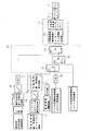
図1では、冷却システム2及び駆動部3を有する、本発明による建設機械1を示している。冷却システム2はビスカスカップリング4を含み、該ビスカスカップリング4は出力側でファン5に接続する。ファン5を、給気、冷却水、作動油等の冷媒を冷却する冷却用空気流を生成するために提供する。
FIG. 1 shows a construction machine 1 according to the invention having a
ビスカスカップリング4を、入力側で、駆動部3のモータ6に接続する。冷却システム2は、駆動部3の周囲温度8及び/又は吸気温度9を記録するために設けるコントローラ7を更に含む。コントローラ7は、任意には、冷却される媒体の温度、つまり給気温度10、冷却水温度11及び/又は作動液温度12を記録するように設けられる。
The
図1で示すように、ファン5を、固定的に取り付ける又は油圧モータに取り付ける代わりに、モータ6に取り付けたビスカスカップリング4の助けを借りて駆動できる。実際のファン回転速度13は、ビスカスカップリング4に組込んだセンサ31によって記録できる。実際のファン回転速度13を、ビスカスカップリング4からコントローラ7に送信できる。
As shown in FIG. 1, the
コントローラ7の更なる要素は、制御部14である。操作量15をビスカスカップリング4に送信するために、制御部14を設ける。
A further element of the
また、図1では、コントローラ7を駆動部3のモータ6に接続し、駆動部3のモータ6に関する定格回転速度16及び/又は負荷率17を記録するように構成していることを、示している。コントローラ7は、記録された信号8、9、10、11、12、13、16、17を用いて、又は少なくともこれらの中から幾つか選択した信号を用いて、操作量15を生成できる。
FIG. 1 also shows that the
また、コントローラ7は、記録負荷係数及び記録周囲温度8又は吸気温度9によって目標ファン回転速度を決定するために提供されるマッピング18を含む。また、コントローラ7は、記録信号8、9、10、11、12、13、16、17の平均を形成するために提供する手段19を含む。ここでは、コントローラ7は、各測定量につき、サンプリングレート10ミリ秒〜360秒で、2〜1000個の複数の値を記録するように構成される。10ミリ秒〜360秒の範囲における固定サンプリングレートで、これらの値から平均値を抽出できる。好ましくは、サンプリングレート1秒で20個の値を記録する。また、他の平均化として、移動平均、幾何平均、調和平均、平方平均、又は立方平均によって実行してもよいと考えられる。
The
特定のファン回転速度で変化がある場合に生じる可聴ノイズの差を防止するために、コントローラ7は、ファンに関する回転速度の急激なジャンプを減衰させるために、ランプ関数20を含む。ファン5に対する新たな目標回転速度値がある場合、予め規定した傾きで目標ファン回転速度を段階的に調整して、該新目標回転速度に到達させることができる。オペレータが、回転速度の急激な変化を感じないようにするため、ランプ関数の傾きを、実質的に平坦にするように構成する。他方で、冷却システム2の過熱を防ぐためには、ランプ関数20の傾きを平坦過ぎないようにする。好ましくは、ランプ関数20の傾きを0.1回転/秒〜200回転/秒の範囲に調整する。ランプ関数の傾きを12回転/秒にすると、有利である。
In order to prevent audible noise differences that occur when there is a change at a particular fan speed, the
また、コントローラ7は、コントローラ7の入力量、即ち周囲温度8、吸気温度9、給気温度10、冷却水温度11、作動液温度12、ファン回転速度13、ディーゼルエンジン定格回転速度16、及び/又は負荷係数17を保存するように構成されたメモリ21を含む。特に、周囲温度8の平均値と負荷係数17の平均値を、コントローラ7が必要に応じて検索可能にするために、メモリ21に保存できる。任意には、メモリ21を、入力信号を一時的に保存するためにも、提供する。
Further, the
図2は、コントローラ7の機能について示している。コントローラ7は、制御部14の入力側に配設した評価ロジック22を含む。評価ロジック22は、可能であれば、オペレータに気付かれずにファン回転速度を変化させるために、提供される。ビスカスカップリング4の制御挙動を、評価ロジック22によって、建設機械1の回転速度挙動に連動させることができる。操作量15を生成するために、制御部14は、線形化法23を備えると共に、PI又はPIDコントローラとして任意に実行できる下流のPコントローラ24も備える。線形化法23により、例えば実際のファン回転速度13や定格回転速度16等の入力量に応じて一定又は可変である制御係数Kp、Ki、又はKaを規定する。好ましくは、制御係数を、特定の特性曲線によってビスカスカップリング4の動作点に調整する。
FIG. 2 shows the functions of the
冷却システム2が過熱しないように、評価ロジック22は、冷却システム2の温度10、11、12が上限値に達する、又は上限値を超えるか否かを監視するように、構成された第1ロジック部材25を含む。上限温度に達する又は上限温度を超えた場合、制御部14の第1ロジック部材25は、駆動部3のモータ6の記録された定格回転速度に対応する目標ファン回転速度を送信する。制御部14を急激に反応させないために、ランプ関数20によって目標ファン回転速度を減衰させる。過熱状態の機械を検出したときに備えて、コントローラ7を、実際の温度が上限温度以下に下がった場合でも、任意の停止時間31によって、一定時間は最大ファン回転速度を維持するように、構成する。第1ロジック部材25を、実際の温度が下限温度に到達した又は下限温度以下になったか否かに関して、冷却システム2の動作温度をチェックするように、更にまた構成する(図示せず)。実際の温度が下限温度に到達又は下限温度以下になった場合には、第1ロジック部材25は、目標ファン回転速度を制御部14に渡し、それにより該目標ファン回転速度が、駆動部3のスリップ回転速度に対応するようにする。
In order to prevent the
図2では、更にまた、評価ロジック22は、第2ロジック部材26を含むことを示している。第2ロジック部材26を、駆動部3の定格回転速度16を判別するように、又は定格回転速度の変化の有無を記録するように、構成する。コントローラ7が駆動部3の定格回転速度16を記録する場合、評価ロジック22の更なる第3ロジック部材27により、任意の開始遅延28が終了したか否かをチェックする。駆動部3の定格回転速度16に変化があれば、開始遅延28を有効に切り替え、その結果特定の時間間隔、即ち開始遅延28の間、まずスリップ回転速度を、目標ファン回転速度として制御部14に送る。開始遅延28が終了した場合、第1ロジック部材25、第2ロジック部材26、第3ロジック部材27を、制御部14とメモリ21を接続するように切替えて、特定の目標ファン回転速度を決定するために平均値をメモリ21から検索できるようにする。負荷係数17及び周囲温度8の平均値と保存値とを比較して、目標ファン回転速度をマッピング18から決定できる。制御部14が急激に反応しないように、決定した目標ファン回転速度を、ランプ関数20によって減衰させて、制御部14に渡すことができる。
In FIG. 2, the
それと同時に、現在の負荷係数17及び現在の周囲温度8を、建設機械1の定格回転速度で連続的な変化があった場合に備えて、これらの値を利用可能にするように、メモリ21に保存する。また、平均値を保存することも可能である。
At the same time, the
図3(図3aと図3bで構成)では、ファン回転速度を調節する方法に関する図を示している。まず、駆動部3のモータ6が動作中か否かを調べるためにチェックする。動作中の場合には、コントローラは、冷却システム2の動作温度10、11、12の1つが上限温度に到達した又は超えたか否かをチェックする。到達した又は超えた場合には、コントローラ7は、ファン回転速度をモータ6の定格回転速度と等しく設定する。それと同時に停止時間を有効にし、開始遅延28を無効にする。設定した目標ファン回転速度によって制御部14が急激な反応を起こさないように、まず該目標ファン回転速度をランプ関数20で減衰させる。現在の負荷係数17と周囲温度8及び/又は吸気温度9を、任意に平均化19した後にメモリ21に別々に保存し、それにより特定の温度が限界温度に対応しなくなった場合に備えて、駆動部の現在の状態をコントローラ7が利用できるようにする。減衰させた目標ファン回転速度を、操作量15としてビスカスカップリング4に渡す。ビスカスカップリング4の油量を、必要な目標ファン回転速度をファン5で設定するように、連続的に調節する。
FIG. 3 (composed of FIGS. 3a and 3b) shows a diagram relating to a method of adjusting the fan rotation speed. First, a check is made to check whether the
或いは、モータ6がオンされていた場合、コントローラ7は、冷却システム2の動作温度10、11、12の何れも上限温度に到達していないと決定できる。
Alternatively, when the
過熱の場合の後、温度測定値により過熱状態と決定しなくなれば、目標ファン回転速度を、停止時間中定格回転速度のままにする。動作温度の1つが上限温度に達し、且つ過熱後に停止時間が終了した、つまり冷却システム2の動作温度が上限温度より低く且つ停止段階の時間が経過した、とコントローラ7が決定しない場合、モータ6の動作状況をチェックする。モータが定格回転速度ではない場合、目標ファン回転速度を、ビスカスカップリングのスリップ回転速度と等しく設定する。開始遅延28を有効にした後、ビスカスカップリングの操作量を、制御部14で目標ファン回転速度から生成する。ビスカスカップリングを、スリップ回転速度をファンで調整するように、調節する。
After overheating, if the temperature measurement value does not determine the overheating state, the target fan speed is kept at the rated speed during the stop time. If the
一方で、駆動部3で定格回転速度である場合、クエリは、開始遅延28の終了に関して行われる。開始遅延28が有効な限り、開始遅延は計数され、スリップ回転速度を目標値として、次の制御部14の目標ファン回転速度値に送信される。他方で、終了した開始遅延28についての条件が当てはまる場合には、目標回転速度値を、負荷係数17と周囲温度8の保存値の助けを借りて、保存したマッピング18から生成し、ランプ関数20で減衰させる。その後、駆動部の現在の状態をメモリ21に保存し、それによりこれらの値を、マッピング18から目標回転速度を更新して生成するために、コントローラが利用できるようにする。マッピングから生成した目標回転速度値を、ファンで目標回転速度となるように、制御部14に渡す。
On the other hand, when the drive unit 3 is at the rated rotation speed, the query is performed regarding the end of the
図4では、本発明による建設機械1の典型的な回転速度曲線を表している。従って、建設機械1が停止するアイドリング段階29と、駆動部3のモータ6を定格回転速度16で動作させる敷設及び輸送段階との間で変化が存在している。モータ6の定格回転速度16に応じて、結果的にビスカスカップリング4での入力回転速度に応じて、建設機械の動作状況に対して調整した目標回転速度を、制御部14に送信するために、評価ロジック22に存在するロジック部材25、26、27の調整がある。ビスカスカップリング4での入力回転速度が低い場合に備えて、ビスカスカップリング4を、所定の目標回転速度に僅かだけ調節する。そうした場合に、結果的に、特にアイドリング段階中、目標ファン回転速度をスリップ回転速度まで減速する、つまりビスカスカップリングの出来る限り最低な回転速度にまで減速する。意図的に、アイドリング段階中にファン回転速度を特定せずに済ますことも可能となる。それに関する長所は、ビスカスカップリング4が完全に分断され、加速処理中はビスカスカップリングに殆ど油量がないため、いつ回転速度に急激な変化が起こってもファンが加速しない点である。
FIG. 4 shows a typical rotational speed curve of the construction machine 1 according to the present invention. Therefore, there is a change between an idling
アイドリング29中に駆動部3の定格回転速度16まで回転速度の急激な変化30がある場合、つまりアイドリングから舗装に建設機械が変化する際に、定格回転速度16を記録した後に、コントローラ7による目標ファン回転速度の特定がある前に、開始遅延28が時間切れとなる。制御部14が目標ファン回転速度を受信し、該速度から操作量15を生成する前の開始遅延28を、ビスカスカップリング4のオーバーシュート挙動によって決定し、0.1〜10秒の範囲にできる。好ましくは、開始遅延28は3秒間継続する。
When there is a
回転速度の急激な変化30が起きると、直近の有効な負荷状態及び直近の周囲温度8を、メモリ21から検索でき、マッピング18を使用して目標ファン回転速度に変換できる。平均値を、予め設定したサンプリングレートで記録した測定値からの現在の負荷係数17と現在の周囲温度8から形成する。そうした平均値をメモリ21に保存し、更新する回転速度仕様がある近似サイクルに利用可能にする。
When an
自動目標ファン回転速度調節は、駆動部3の平均負荷が敷設処理中はほんの僅かしか変化しないとする仮定に基づいている。舗道敷設動作からアイドリングに更新して変化したときは、目標ファン回転速度は、スリップ回転速度に等しく設定される。そのため、定格回転速度16での直近の負荷状態と直近の周囲温度は、メモリ21で利用可能なままとなる。
The automatic target fan speed adjustment is based on the assumption that the average load of the drive 3 changes only slightly during the laying process. When the pavement laying operation is changed from idling to idling, the target fan rotation speed is set equal to the slip rotation speed. Therefore, the most recent load state at the rated
他方で、モータ6の負荷レベル、つまり負荷係数17が変化する場合、冷却用空気流は結果的に調整される。ファン5における回転速度の急激な変化を大きくしないために、マッピング18で決定する目標ファン回転速度を、ランプ20によって予め定義した傾きで、規定する。こうして決定した目標ファン回転速度を、ビスカスカップリング4の制御部14に対する入力として使用する。こうして得たファン回転速度仕様を、図4の点線で示している。
On the other hand, if the load level of the
道路舗装機やフィーダ等の建設機械では、最大冷却用空気体積流量は、極めて高温の周囲温度での極端な作業条件に備える場合の他、極めて高いモータ負荷に備える場合にのみ必要になる。しかしながら、そうした動作状態は、まれに発生するため、ファン回転速度は大部分の適用事例に対して低減でき、その結果建設機械の騒音レベルは低くなる。ファンを最大設計点で運転しなければ、ファン回転速度は低減するため燃料を節約できる。油圧駆動ファンと比べて、ビスカスカップリングは、ファン回転速度を低減して運転中は損失が少なく、その結果ビスカスカップリングを有するシステムは、全体的に効率が良くなる。これまで、調節ビスカスカップリングは、回転速度プロファイルのために道路舗装機では使用されなかった。調節ファン回転速度の大きな利点は、機械の過熱可能性に反応する時間にある。冷媒の昇温過程時の負荷係数や周囲温度は既に保存されているため、冷却装置で温度が上昇する前に、ファン回転速度を設定できる。その結果、過熱が起きる前に冷却装置によって正確な空気流に調整できるため、モータ冷却装置ファンシステムのダウンタイムを回避できる。 In construction machines such as road pavers and feeders, the maximum cooling air volume flow is only required when preparing for extremely high motor loads as well as for extreme working conditions at extremely high ambient temperatures. However, since such operating conditions rarely occur, the fan speed can be reduced for most applications, resulting in a lower noise level for construction machinery. If the fan is not operated at the maximum design point, the fan rotation speed is reduced and fuel can be saved. Compared with hydraulically driven fans, viscous coupling reduces fan rotation speed and reduces losses during operation, resulting in a system with viscous coupling that is generally more efficient. Until now, regulated viscous couplings have not been used in road pavers due to rotational speed profiles. A significant advantage of the regulated fan rotation speed is the time to react to the machine's potential for overheating. Since the load coefficient and the ambient temperature during the temperature raising process of the refrigerant are already stored, the fan rotation speed can be set before the temperature rises in the cooling device. As a result, it is possible to adjust the air flow accurately by the cooling device before overheating occurs, thereby avoiding downtime of the motor cooling device fan system.
1 建設機械
2 冷却システム
3 駆動部
4 ビスカスカップリング
5 ファン
6 モータ
7 コントローラ
8 周囲温度
9 吸気温度
10 給気温度
11 冷却水温度
12 作動液温度
13 回転速度
14 制御部
15 操作量
16 定格回転速度
17 負荷係数
18 マッピング
19 手段
20 ランプ関数
21 メモリ
22 評価ロジック
23 線形化法
24 下流Pコントローラ
25 第1ロジック部材
26 第2ロジック部材
27 第3ロジック部材
28 開始遅延
29 アイドリング段階
30 回転速度ジャンプ
31 センサ
DESCRIPTION OF SYMBOLS 1
Claims (13)
建設機械(1)は、道路舗装機又はフィーダであり、
前記冷却システム(2)は、
入力側を前記駆動部(3)に接続し、出力側を前記ファン(5)に接続する調節可能なビスカスカップリング(4)と、
前記ビスカスカップリング(4)に及び前記駆動部(3)に接続するコントローラ(7)と、を更に含み、
前記駆動部(3)の負荷係数(17)を記録するために、前記コントローラ(7)を、前記駆動部(3)に接続し、
前記コントローラ(7)は、前記駆動部(3)の前記負荷係数(17)に応じて前記ビスカスカップリング(4)を駆動するように構成されることを特徴とする建設機械。 To generate the cooling air flow, the driving section (3), viewed it contains a cooling system (2) having a fan (5), automatically construction machine to adjust the fan speed (1) met And
Construction machine (1) is a road paving machine or feeder ,
The cooling system (2)
An adjustable viscous coupling (4) connecting the input side to the drive (3) and connecting the output side to the fan (5);
Wherein further comprising及beauty before SL driver in viscous coupling (4) and a controller connected to (3) (7), a,
To record load factor (1 7) of the driving unit (3), wherein the controller (7), connected to the drive unit (3),
It said controller (7), a construction machine, wherein Rukoto configured such that the drive the viscous coupling (4) according to the load factor of the driving unit (3) (17).
前記ビスカスカップリング(4)は、前記ビスカスカップリング(4)の前記出力側に特定のファン回転速度が設定されるようにして、異なる動作パラメータに応じて調整され、
前記冷却システム(2)は、前記ビスカスカップリング(4)に及び前記駆動部(3)に接続するコントローラ(7)を備え、
前記コントローラ(7)は、
前記駆動部(3)の負荷係数(17)を記録し、
前記駆動部(3)の前記負荷係数(17)に応じて前記ビスカスカップリング(4)を駆動することを特徴とする方法。 The cooling system (2) of the road paving machine or feeder is automatically connected by a viscous coupling (4) with the input side connected to the drive (3) and the output side connected to the fan (5) of the cooling system (2). A method of adjusting and controlling
Said viscous coupling (4), the in the so that certain of the fan rotation speed is set to the output side of the viscous coupling (4) is adjusted according to different operating parameters,
The cooling system (2) comprises a controller (7) connected to the viscous coupling (4) and to the drive (3),
The controller (7)
Record the load factor (17) of the drive (3),
A method of driving the viscous coupling (4) according to the load coefficient (17) of the drive unit (3) .
Applications Claiming Priority (2)
| Application Number | Priority Date | Filing Date | Title |
|---|---|---|---|
| EP11004512.7 | 2011-06-01 | ||
| EP11004512.7A EP2530273B1 (en) | 2011-06-01 | 2011-06-01 | Construction machine with automatic ventilator rotation speed regulator |
Publications (2)
| Publication Number | Publication Date |
|---|---|
| JP2012251553A JP2012251553A (en) | 2012-12-20 |
| JP6029324B2 true JP6029324B2 (en) | 2016-11-24 |
Family
ID=44650769
Family Applications (1)
| Application Number | Title | Priority Date | Filing Date |
|---|---|---|---|
| JP2012123421A Active JP6029324B2 (en) | 2011-06-01 | 2012-05-30 | Construction machine that automatically adjusts fan rotation speed |
Country Status (5)
| Country | Link |
|---|---|
| US (1) | US9376954B2 (en) |
| EP (1) | EP2530273B1 (en) |
| JP (1) | JP6029324B2 (en) |
| CN (1) | CN102808683B (en) |
| PL (1) | PL2530273T3 (en) |
Families Citing this family (7)
| Publication number | Priority date | Publication date | Assignee | Title |
|---|---|---|---|---|
| DE102010031835A1 (en) * | 2010-07-22 | 2012-01-26 | Liebherr-Werk Nenzing Gmbh | fan control |
| CN108291763B (en) * | 2015-09-30 | 2021-04-13 | 伊莱克斯家用产品公司 | Temperature control of refrigeration cavity at low ambient temperature conditions |
| JP6628311B2 (en) * | 2016-03-24 | 2020-01-08 | Necプラットフォームズ株式会社 | Fan control device, cooling fan system, computer device, fan control method and program |
| JP6539629B2 (en) * | 2016-09-29 | 2019-07-03 | 日立建機株式会社 | Clutch control device for work machine |
| PL3569764T3 (en) * | 2018-05-15 | 2021-12-27 | Joseph Vögele AG | Method for predictive control of a road paver |
| CN112031916A (en) * | 2020-09-04 | 2020-12-04 | 北京理工大学 | Engine cooling fan speed regulation control system, device and terminal equipment |
| CN114337467B (en) * | 2021-12-23 | 2024-01-12 | 昂宝电子(上海)有限公司 | Method for adjusting motor rotation speed and computer storage medium |
Family Cites Families (75)
| Publication number | Priority date | Publication date | Assignee | Title |
|---|---|---|---|---|
| US4124001A (en) * | 1976-06-30 | 1978-11-07 | Fmc Corporation | Electronic speed control for a variable speed fan drive |
| US4292813A (en) * | 1979-03-08 | 1981-10-06 | Whirlpool Corporation | Adaptive temperature control system |
| JPS57132026U (en) * | 1981-02-13 | 1982-08-17 | ||
| US4425766A (en) | 1982-05-17 | 1984-01-17 | General Motors Corporation | Motor vehicle cooling fan power management system |
| FR2531489B1 (en) | 1982-08-05 | 1987-04-03 | Marchal Equip Auto | COOLING DEVICE OF AN INTERNAL COMBUSTION ENGINE |
| FR2554165B1 (en) | 1983-10-28 | 1988-01-15 | Marchal Equip Auto | METHOD FOR CONTROLLING THE TEMPERATURE OF THE COOLING LIQUID OF AN INTERNAL COMBUSTION ENGINE AND DEVICE FOR IMPLEMENTING IT |
| GB8419784D0 (en) | 1984-08-02 | 1984-09-05 | Lucas Elect Electron Syst | Engine cooling system |
| JPS61167113A (en) | 1985-01-19 | 1986-07-28 | Honda Motor Co Ltd | Cooling control device of car engine |
| JPS63124820A (en) * | 1986-11-12 | 1988-05-28 | Toyota Motor Corp | Revolution speed controller of cooling fan of internal combustion engine |
| GB8726966D0 (en) * | 1987-11-18 | 1987-12-23 | Jaguar Cars | Cooling systems |
| KR960001985B1 (en) * | 1991-06-07 | 1996-02-08 | 삼성전자주식회사 | Refrigerator |
| US5477827A (en) * | 1994-05-16 | 1995-12-26 | Detroit Diesel Corporation | Method and system for engine control |
| JPH08177887A (en) | 1994-12-22 | 1996-07-12 | Toyota Motor Corp | Fan coupling |
| TW294771B (en) * | 1995-01-30 | 1997-01-01 | Gastar Co Ltd | |
| US5657722A (en) * | 1996-01-30 | 1997-08-19 | Thomas J. Hollis | System for maintaining engine oil at a desired temperature |
| US5507251A (en) * | 1995-06-06 | 1996-04-16 | Hollis; Thomas J. | System for determining the load condition of an engine for maintaining optimum engine oil temperature |
| JP3039319B2 (en) | 1995-05-31 | 2000-05-08 | トヨタ自動車株式会社 | Control device for electric cooling fan in engine cooling system |
| US5584371A (en) * | 1995-08-31 | 1996-12-17 | Eaton Corporation | Viscous fan drive system logic |
| US5855266A (en) * | 1995-09-18 | 1999-01-05 | Rockford Powertrain, Inc. | Fan clutch for vehicles configured for low engine speed |
| US5947247A (en) * | 1995-09-18 | 1999-09-07 | Rockford Powertrain, Inc. | Continuously variable fan drive clutch |
| JP3633190B2 (en) | 1997-03-11 | 2005-03-30 | 株式会社デンソー | Automotive heat exchanger |
| DE19710384A1 (en) * | 1997-03-13 | 1998-09-17 | Behr Gmbh & Co | Device for controlling rotational speed for e.g. ventilator for cooling components of vehicle |
| DE19728814A1 (en) | 1997-07-05 | 1999-01-07 | Behr Thermot Tronik Gmbh & Co | Cooling system for an internal combustion engine of a motor vehicle |
| JP3799803B2 (en) * | 1998-03-06 | 2006-07-19 | 日産自動車株式会社 | Control device for cooling fan |
| ITTO980348A1 (en) | 1998-04-24 | 1999-10-24 | Gate Spa | MINIMUM ELECTRIC CONSUMPTION CONTROL SYSTEM FOR A COOLING SYSTEM FOR AN INTERNAL COMBUSTION ENGINE. |
| AT407206B (en) * | 1998-05-14 | 2001-01-25 | Va Tech Elin Transformatoren G | METHOD AND ARRANGEMENT FOR DETERMINING STATE SIZES |
| IT1308421B1 (en) | 1999-03-11 | 2001-12-17 | Fiat Ricerche | COOLING SYSTEM FOR AN INTERNAL COMBUSTION ENGINE. |
| JP3566147B2 (en) * | 1999-09-14 | 2004-09-15 | 本田技研工業株式会社 | Hybrid vehicle cooling fan failure detection device |
| US6346789B1 (en) | 1999-11-29 | 2002-02-12 | Honeywell International Inc. | Motor step-less speed control with active feedback of phase detector |
| US6463891B2 (en) | 1999-12-17 | 2002-10-15 | Caterpillar Inc. | Twin fan control system and method |
| JP4285866B2 (en) | 1999-12-22 | 2009-06-24 | 株式会社小松製作所 | Hydraulically driven cooling fan |
| FR2803334B1 (en) | 1999-12-30 | 2002-03-22 | Valeo Thermique Moteur Sa | DEVICE FOR REGULATING THE COOLING OF A MOTOR VEHICLE ENGINE IN A HOT START STATE |
| DE10016435B4 (en) * | 2000-04-01 | 2014-03-13 | Deere & Company | Ventilation device for an agricultural vehicle |
| JP2002098245A (en) | 2000-09-21 | 2002-04-05 | Denso Corp | Flow control valve, and cooling system for internal combustion engine using the same |
| US6453853B1 (en) | 2000-12-04 | 2002-09-24 | Detroit Diesel Corporation | Method of controlling a variable speed fan |
| JP2002213242A (en) * | 2001-01-19 | 2002-07-31 | Nissan Motor Co Ltd | Cooling controller for movable body |
| US6772714B2 (en) * | 2001-08-16 | 2004-08-10 | Deere & Company | Electronic fan control |
| US6648115B2 (en) * | 2001-10-15 | 2003-11-18 | General Motors Corporation | Method for slip power management of a controllable viscous fan drive |
| JP3466177B2 (en) | 2002-01-09 | 2003-11-10 | 日本サーモスタット株式会社 | Control method of electronic thermostat |
| JP2004068640A (en) | 2002-08-02 | 2004-03-04 | Hitachi Constr Mach Co Ltd | Engine cooling device |
| DE10315402A1 (en) * | 2003-04-04 | 2004-11-04 | Voith Turbo Gmbh & Co. Kg | Drive system and method for optimizing the energy supply for a cooling system of a drive system |
| JP2004340373A (en) * | 2003-04-21 | 2004-12-02 | Usui Kokusai Sangyo Kaisha Ltd | Control method for externally controlled fan clutch |
| US7178656B2 (en) * | 2003-07-21 | 2007-02-20 | Borgwarner Inc. | Hydraulic controlled fan clutch with integral cooling |
| DE10337413A1 (en) | 2003-08-14 | 2005-03-10 | Daimler Chrysler Ag | Method of regulating the flow of coolant with a heater shut-off valve |
| US7047911B2 (en) * | 2003-08-27 | 2006-05-23 | Borgwarner Inc. | Hydraulic fan drive system employing binary control strategy |
| US6880497B1 (en) * | 2003-09-25 | 2005-04-19 | Detroit Diesel Corporation | System and method for controlling fan activation based on intake manifold air temperature and time in an EGR system |
| DE10348130A1 (en) | 2003-10-16 | 2005-05-12 | Daimler Chrysler Ag | Cooling system for an internal combustion engine of a motor vehicle |
| JP2005214155A (en) | 2004-02-02 | 2005-08-11 | Nissan Diesel Motor Co Ltd | Fan clutch control device |
| JP2005351286A (en) | 2004-06-08 | 2005-12-22 | Shin Caterpillar Mitsubishi Ltd | Controller of i/o rotational speed ratio variable type clutch |
| JP4065869B2 (en) | 2004-10-05 | 2008-03-26 | 三菱電機株式会社 | Cooling system control device for internal combustion engine |
| US7165514B2 (en) * | 2004-10-06 | 2007-01-23 | Deere & Company | Variable speed fan drive |
| JP4753278B2 (en) * | 2004-10-12 | 2011-08-24 | 臼井国際産業株式会社 | Control method of externally controlled fan clutch |
| SE527674C2 (en) * | 2004-10-27 | 2006-05-09 | Atlas Copco Rock Drills Ab | Drilling unit and method for controlling a fan in the same |
| US7058477B1 (en) * | 2004-11-23 | 2006-06-06 | Howard Rosen | Thermostat system with remote data averaging |
| US7066114B1 (en) | 2004-12-10 | 2006-06-27 | General Motors Corporation | Reverse fan operation for vehicle cooling system |
| US7249664B2 (en) * | 2005-03-14 | 2007-07-31 | Borgwarner Inc. | Fan drive having pressure control (fluid) of a wet friction fan drive |
| US7484378B2 (en) * | 2005-05-10 | 2009-02-03 | Emp Advanced Development, Llc | Cooling system and method for cooling a heat producing system |
| US20090025997A1 (en) * | 2005-05-18 | 2009-01-29 | Norihiro Ishii | Hydraulic Drive Vehicle with Cooling System |
| US7134406B1 (en) * | 2005-09-08 | 2006-11-14 | Deere & Company | Cooling fan control for improved engine load acceptance |
| US7407046B2 (en) * | 2005-09-26 | 2008-08-05 | Usui International Corp. | Adaptive control of externally controlled fan drive |
| JP4649354B2 (en) | 2006-03-20 | 2011-03-09 | キャタピラー エス エー アール エル | Cooling fan control device and work machine cooling fan control device |
| CN101432507B (en) | 2006-04-28 | 2012-05-02 | 斯堪尼亚有限公司 | Cooling fan arrangement at a vehicle |
| JP2007321622A (en) | 2006-05-31 | 2007-12-13 | Hino Motors Ltd | Method and device for detecting malfunction of fan clutch |
| US7397354B1 (en) | 2007-01-09 | 2008-07-08 | Deere & Company | Cooling system monitoring system |
| US7865750B2 (en) * | 2007-02-06 | 2011-01-04 | International Business Machines Corporation | Fan speed control from adaptive voltage supply |
| US7863839B2 (en) * | 2007-03-30 | 2011-01-04 | Caterpillar Inc | Fan speed control system |
| TW200925839A (en) | 2007-12-13 | 2009-06-16 | Inventec Corp | Intelligent cooling fan device and fan rotation speed controlling method thereof |
| US8196553B2 (en) | 2008-01-30 | 2012-06-12 | Chrysler Group Llc | Series electric-mechanical water pump system for engine cooling |
| US8241008B2 (en) * | 2009-02-26 | 2012-08-14 | Standard Microsystems Corporation | RPM controller using drive profiles |
| EP2412948B1 (en) * | 2009-03-24 | 2018-08-22 | Komatsu, Ltd. | Cooling fan driving device and fan rotation number control method |
| DE102009026613A1 (en) * | 2009-05-29 | 2010-12-02 | Deere & Company, Moline | Device for controlling the temperature of a charge air flow passing through an intercooler |
| EP2282029B2 (en) | 2009-06-29 | 2022-04-20 | Joseph Vögele AG | Self-propelled machine |
| CN102191991A (en) * | 2010-03-03 | 2011-09-21 | 株式会社电装 | Controller for engine cooling system |
| JP5041019B2 (en) | 2010-03-15 | 2012-10-03 | トヨタ自動車株式会社 | Water-cooled engine cooling system |
| US8868250B2 (en) * | 2010-09-28 | 2014-10-21 | Cisco Technology, Inc. | Fan speed control |
-
2011
- 2011-06-01 EP EP11004512.7A patent/EP2530273B1/en active Active
- 2011-06-01 PL PL11004512T patent/PL2530273T3/en unknown
-
2012
- 2012-05-29 US US13/482,034 patent/US9376954B2/en active Active
- 2012-05-30 JP JP2012123421A patent/JP6029324B2/en active Active
- 2012-06-01 CN CN201210180558.3A patent/CN102808683B/en active Active
Also Published As
| Publication number | Publication date |
|---|---|
| US9376954B2 (en) | 2016-06-28 |
| PL2530273T3 (en) | 2020-11-16 |
| US20120305232A1 (en) | 2012-12-06 |
| EP2530273A1 (en) | 2012-12-05 |
| CN102808683B (en) | 2016-03-02 |
| CN102808683A (en) | 2012-12-05 |
| JP2012251553A (en) | 2012-12-20 |
| EP2530273B1 (en) | 2020-04-08 |
Similar Documents
| Publication | Publication Date | Title |
|---|---|---|
| JP6029324B2 (en) | Construction machine that automatically adjusts fan rotation speed | |
| AU2019204467B2 (en) | Systems and methods for controlling a variable speed water pump | |
| EP2715085B1 (en) | Engine cooling fan speed control system | |
| EP1284344B1 (en) | Electronic fan control | |
| US6431127B2 (en) | Ventilation device | |
| JP4586017B2 (en) | Drive system and method for optimizing power supply to drive system cooling system | |
| JP2005509116A (en) | Drive unit for vehicle | |
| US8006813B2 (en) | Method and arrangement for machine cooling | |
| US9670930B2 (en) | Construction machine with automatic fan rotational speed regulation | |
| JP2007518915A (en) | Method for operating the drive transmission system of an automobile | |
| JP7206757B2 (en) | Cooling system for vehicle and control method thereof | |
| SE534573C2 (en) | Procedure and system for automatic controlled coupling | |
| JP5685277B2 (en) | Initial setting method of mechanical automatic transmission | |
| JP4012421B2 (en) | Engine cooling system | |
| JP5752723B2 (en) | Initial setting method of mechanical automatic transmission | |
| JP6580909B2 (en) | Automatic transmission oil temperature control device | |
| KR102115061B1 (en) | System and method for controlling pump performance in a transmission | |
| JP5860824B2 (en) | Initial setting method of mechanical automatic transmission | |
| KR20140084465A (en) | Cooling System for Construction Machinery | |
| JP2003020944A (en) | Construction machine with temperature sensitive type cooling fan |
Legal Events
| Date | Code | Title | Description |
|---|---|---|---|
| A621 | Written request for application examination |
Free format text: JAPANESE INTERMEDIATE CODE: A621 Effective date: 20150130 |
|
| A977 | Report on retrieval |
Free format text: JAPANESE INTERMEDIATE CODE: A971007 Effective date: 20150831 |
|
| A131 | Notification of reasons for refusal |
Free format text: JAPANESE INTERMEDIATE CODE: A131 Effective date: 20150901 |
|
| A521 | Request for written amendment filed |
Free format text: JAPANESE INTERMEDIATE CODE: A523 Effective date: 20151130 |
|
| A02 | Decision of refusal |
Free format text: JAPANESE INTERMEDIATE CODE: A02 Effective date: 20160426 |
|
| A521 | Request for written amendment filed |
Free format text: JAPANESE INTERMEDIATE CODE: A523 Effective date: 20160823 |
|
| A911 | Transfer to examiner for re-examination before appeal (zenchi) |
Free format text: JAPANESE INTERMEDIATE CODE: A911 Effective date: 20160902 |
|
| TRDD | Decision of grant or rejection written | ||
| A01 | Written decision to grant a patent or to grant a registration (utility model) |
Free format text: JAPANESE INTERMEDIATE CODE: A01 Effective date: 20161004 |
|
| A61 | First payment of annual fees (during grant procedure) |
Free format text: JAPANESE INTERMEDIATE CODE: A61 Effective date: 20161018 |
|
| R150 | Certificate of patent or registration of utility model |
Ref document number: 6029324 Country of ref document: JP Free format text: JAPANESE INTERMEDIATE CODE: R150 |
|
| R250 | Receipt of annual fees |
Free format text: JAPANESE INTERMEDIATE CODE: R250 |
|
| R250 | Receipt of annual fees |
Free format text: JAPANESE INTERMEDIATE CODE: R250 |
|
| R250 | Receipt of annual fees |
Free format text: JAPANESE INTERMEDIATE CODE: R250 |
|
| R250 | Receipt of annual fees |
Free format text: JAPANESE INTERMEDIATE CODE: R250 |
|
| R250 | Receipt of annual fees |
Free format text: JAPANESE INTERMEDIATE CODE: R250 |