JP6025430B2 - Transmitter - Google Patents
Transmitter Download PDFInfo
- Publication number
- JP6025430B2 JP6025430B2 JP2012155716A JP2012155716A JP6025430B2 JP 6025430 B2 JP6025430 B2 JP 6025430B2 JP 2012155716 A JP2012155716 A JP 2012155716A JP 2012155716 A JP2012155716 A JP 2012155716A JP 6025430 B2 JP6025430 B2 JP 6025430B2
- Authority
- JP
- Japan
- Prior art keywords
- error
- satellite
- satellite clock
- factor
- positioning
- Prior art date
- Legal status (The legal status is an assumption and is not a legal conclusion. Google has not performed a legal analysis and makes no representation as to the accuracy of the status listed.)
- Active
Links
Images


Description
この発明は、衛星測位に使用される測位用補正データを送信する送信装置および測位用補正データを用いて衛星測位を行う測位装置に関する。 The present invention relates to a transmission device that transmits correction data for positioning used for satellite positioning, and a positioning device that performs satellite positioning using the correction data for positioning.
測位衛星を用いた測位である衛星測位では、衛星クロック誤差と、衛星クロック誤差以外の誤差である他要因誤差(例えば、衛星軌道誤差)が生ずることが知られている。そして、送信装置は、準天頂衛星を介して、これらの誤差の情報が含まれる測位用補正データを測位装置に送信する。一方、測位装置は、準天頂衛星を介して送信された測位用補正データを受信し、受信した測位用補正データに含まれる衛星クロック誤差と、他要因誤差とを元に補正を行った上で、衛星測位を実施する(例えば、特許文献1)。 In satellite positioning, which is positioning using a positioning satellite, it is known that satellite clock errors and other factor errors (for example, satellite orbit errors) that are errors other than satellite clock errors occur. Then, the transmission device transmits the positioning correction data including the information of these errors to the positioning device via the quasi-zenith satellite. On the other hand, the positioning device receives the correction data for positioning transmitted via the quasi-zenith satellite, and performs correction based on the satellite clock error included in the received positioning correction data and other factor errors. Satellite positioning is performed (for example, Patent Document 1).
送信装置において、衛星クロック誤差の送信タイミングと、他要因誤差の送信タイミングとは異なり、他要因誤差の送信後に、所定の時間を経て、衛星クロック誤差が送信される。
そして、測位装置では、衛星クロック誤差と、当該衛星クロック誤差の送信時よりも所定の時間前の過去に送信された他要因誤差とが用いられて衛星測位が行われる。しかし、衛星クロック誤差の送信時において、他要因誤差の値は、所定の時間を経たことにより変化しているため、補正が正確に行われず、衛星測位の精度が劣化するという課題がある。
In the transmission device, the transmission timing of the satellite clock error is different from the transmission timing of the other factor error, and the satellite clock error is transmitted after a predetermined time after the transmission of the other factor error.
In the positioning device, satellite positioning is performed using the satellite clock error and the other factor error transmitted in the past a predetermined time before the transmission of the satellite clock error. However, when the satellite clock error is transmitted, the value of the other factor error changes due to the passage of a predetermined time. Therefore, there is a problem that correction is not performed accurately and the accuracy of satellite positioning deteriorates.
この発明は前記のような課題を解決することを主な目的とするもので、衛星測位の精度を向上できる送信装置を実現することを主な目的とする。 The main object of the present invention is to solve the above-described problems, and it is a main object of the present invention to realize a transmission apparatus capable of improving the accuracy of satellite positioning.
この発明に係る送信装置は、
衛星測位に用いられる誤差のうち衛星クロック誤差以外の誤差である他要因誤差を送信した後に、所定の周期で到来する衛星クロック誤差送信タイミングにおいて衛星クロック誤差を送信する送信装置であって、
他要因誤差の時間変化を監視し、衛星クロック誤差送信タイミングの到来時に、送信済みの他要因誤差と、衛星クロック誤差送信タイミングの到来時の他要因誤差との差を他要因誤差変動量として算出し、送信対象の衛星クロック誤差に、算出した他要因誤差変動量を含める他要因誤差変動量算出部と、
前記他要因誤差変動量算出部により他要因誤差変動量が含められた衛星クロック誤差を送信する送信部と
を備えることを特徴とする。
The transmission device according to the present invention is:
After sending the other factors erroneous difference is an error other than the satellite clock error of the error used in the satellite positioning, a transmitting apparatus for transmitting satellite clock erroneous difference in the satellite clock error transmission timing that arrives at a predetermined period,
Monitoring the temporal change of the difference erroneous other factors, upon the arrival of the satellite clock error transmission timing, Sent and other factors erroneous difference, other factors error variation of the difference between the other factors error of the time of arrival of the satellite clock error transmission timing calculated as the amount, the satellite clock error of transmission target, and other factors error variation amount calculating portion including the calculated other factors error variation amount,
Characterized in that it comprises a transmitter for transmitting the other factors error variation amount calculating section by the satellite clock erroneous difference other factors error variation amount were included.
この発明に係る送信装置は、衛星クロック誤差の送信時における他要因誤差の値の変動量を衛星クロック誤差の値に含めて送信する。
そのため、衛星クロック誤差の値を受信した測位装置では、衛星クロック誤差についての補正とともに、他要因誤差の補正も並行して行うことができ、衛星測位の精度を向上できる。
The transmitting apparatus according to the present invention transmits a variation amount of the value of the other factor error when transmitting the satellite clock error in the satellite clock error value.
Therefore, the positioning device that has received the value of the satellite clock error can perform correction of other factor errors in parallel with correction of the satellite clock error, thereby improving the accuracy of satellite positioning.
実施の形態1.
(1)測位用補正データ伝送システムの構成
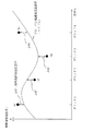
図1は、測位用補正データ伝送システムの構成の例を示す図である。
(1) Configuration of Positioning Correction Data Transmission System FIG. 1 is a diagram illustrating an example of a configuration of a positioning correction data transmission system.
測位用補正データ伝送システム500は、GPS(Global Positioning System)衛星300a〜300nと、電子基準点702a〜702nと、センター局100と、準天頂衛星400と、測位装置201とを備える。
The positioning correction data transmission system 500 includes GPS (Global Positioning System) satellites 300a to 300n,
GPS衛星300は、例えば特許文献1と同様に測位情報701を送信する。
電子基準点702は、例えば特許文献1と同様に測位情報701を受信して、電子基準点702とGPS衛星300との疑似距離、ドップラ周波数、搬送波位相などを含む電子基準点情報700を生成してセンター局100に送信する。電子基準点702は、例えば日本各地に約1000点程度設置されている。
For example, the
For example, the
センター局100は、送信装置101を備える。
送信装置101は、電子基準点702のそれぞれから電子基準点情報700を受信し、測位用補正データ600を生成する。そして、送信装置101は、例えばセンター局100のアンテナを介し、準天頂衛星400に測位用補正データ600を送信(アップリンク)する。
準天頂衛星400は、受信した測位用補正データ600を測位装置201に送信(ダウンリンク)する。
測位装置201は、例えば自動車などの移動体に搭載される。測位装置201は、ユーザ端末とも称する。測位装置201は、GPS衛星300から送信される測位情報701と準天頂衛星400から送信される測位用補正データ600とに基づき、衛星測位を行う。
The
The
The quasi-zenith satellite 400 transmits the received
The
(2)ブロックの説明
図2は、ブロックの例を示す図である。
図3は、分割された地域とグリッドとの関係を示す図である。
図4は、グリッドと電子基準点との関係を示す図である。
(2) Description of Block FIG. 2 is a diagram illustrating an example of a block.
FIG. 3 is a diagram illustrating the relationship between the divided areas and the grid.
FIG. 4 is a diagram illustrating the relationship between the grid and the electronic reference point.
まず、ブロックについて説明する。
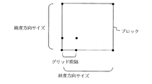
例えば日本で測位を行う場合、日本の領土が図2の例に示されるように所定の緯度サイズと経度サイズとからなる12個のブロック(B1〜B12)に分割される。なお、分割されるブロックの数は限定されるものではない。
すなわち、ブロックは「地域」に対応し、以降の説明において「ブロック」は、「地域」とも「網」とも称する。なお、ブロックの形状は、四角形に限定されるものではない。
First, the block will be described.
For example, when positioning is performed in Japan, the Japanese territory is divided into 12 blocks (B1 to B12) having a predetermined latitude size and longitude size as shown in the example of FIG. Note that the number of blocks to be divided is not limited.
That is, the block corresponds to “region”, and “block” is also referred to as “region” or “network” in the following description. Note that the shape of the block is not limited to a quadrangle.
そして、図3に示すように、1つのブロック内は、例えば格子状に複数のグリッドが定義される。グリッド間隔は、例えば60km程度である。なお、グリッドは、ブロック間で重複しないように定義されている。
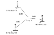
一方、グリッドは、図4に示すように、複数の電子基準点702の間に定義される。
図4の例の場合、送信装置101は、電子基準点702a〜cのそれぞれから受信する電子基準点情報に基づき、グリッドにおける対流圏遅延誤差の値と電離層遅延誤差の値とを算出する。なお、以降の説明において、例えば「対流圏遅延誤差の値」は、単に「対流圏遅延誤差」と称する。他の誤差についても同様に「の値」を省略する。
Then, as shown in FIG. 3, a plurality of grids are defined, for example, in a lattice shape in one block. The grid interval is about 60 km, for example. The grid is defined so as not to overlap between blocks.
On the other hand, the grid is defined between a plurality of
In the case of the example in FIG. 4, the transmitting
(3)測位用補正データの説明
図5は、測位用補正データの例を示す図である。
図5に送信装置101もしくは準天頂衛星400から送信される測位用補正データ600の例を示す。なお、T=30秒以降の図示は省略する。
測位用補正データ600は、例えば30秒を1周期で構成されている。なお、1周期の時間は限定されるものではない。
また、この1周期分のデータのセットをデータフレームと称する。
そして、T=30秒以降、送信装置101はデータフレームを繰り返し送信する。
(3) Description of Positioning Correction Data FIG. 5 is a diagram illustrating an example of positioning correction data.
FIG. 5 shows an example of
The
A set of data for one period is referred to as a data frame.
Then, after T = 30 seconds, the
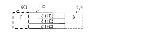
測位用補正データ600には、複数の時刻タグ601が含まれている。
時刻タグ601には、送信装置101において修正衛星クロック誤差602や衛星固有誤差603や地域固有誤差604などが生成された時刻が示されている。
The
The
そして、測位用補正データ600には、時刻タグ601に対応づけられた修正衛星クロック誤差602と地域固有誤差604とのデータセットが1周期の間に複数含まれる。換言すると、時刻タグ601に対応づけられた修正衛星クロック誤差602と地域固有誤差604とのデータセットが1つのデータフレームに複数含まれる。
例えば、図5の例では、時刻タグ601C「T=10」と時刻タグ601D「T=15」との間に、時刻タグ601C「T=10」に対応づけられた修正衛星クロック誤差602Cと地域固有誤差604C「B5、B6」とが配置されている。そして、この時刻タグ601C「T=10」と時刻タグ601C「T=10」に対応づけられた修正衛星クロック誤差602Cと地域固有誤差604C「B5、B6」とが1つのデータセットである。ここで、例えば、図5の時刻タグ601C「T=10」と時刻タグ601C「T=10」に対応づけられた修正衛星クロック誤差602Cと地域固有誤差604Cとのデータセットを「T=10のデータセット」と称する。
図5の例では、時刻タグ601と修正衛星クロック誤差602と地域固有誤差604とのデータセットが1周期の間に6セット含まれている。なお、このデータセットの数は限定されるものではない。
The
For example, in the example of FIG. 5, between the
In the example of FIG. 5, six data sets of the
また、1周期内のデータセットのうちの1つに、衛星固有誤差603が含まれている。
図5の例では、「T=0のデータセット」に衛星固有誤差603が含まれている。
One of the data sets in one cycle includes a satellite
In the example of FIG. 5, the satellite
衛星固有誤差603には、例えば、衛星軌道誤差と周波数間バイアスとがGPS衛星300ごとに含まれる。なお、衛星固有誤差603には、GPS衛星300ごとの衛星軌道誤差もしくは、GPS衛星300ごとの周波数間バイアスとのいずれか一方のみが含まれていてもよい。ここで、衛星固有誤差603は、ブロックによって値が変わらず、GPS衛星300ごとに決定される誤差である。
The satellite
そして、地域固有誤差604には、例えば、対流圏遅延誤差と電離層遅延誤差とがブロックごとに含まれる。なお、地域固有誤差604には、ブロックごとの対流圏遅延誤差と電離層遅延誤差とのいずれか一方のみが含まれていてもよい。そして、地域固有誤差604は、ブロックごとの測位補強情報に対応する。
例えば、図5の「T=0のデータセット」の地域固有誤差604Aには、図2に示すブロック1(B1)の対流圏遅延誤差と電離層遅延誤差、及び、図2に示すブロック2(B2)の対流圏遅延誤差と電離層遅延誤差とが含まれる。
そして、例えば、ブロック1の対流圏遅延誤差と電離層遅延誤差には、ブロック1内に定義されたグリッドごとの対流圏遅延誤差と電離層遅延誤差とが示される。
The region-
For example, the region-
For example, the troposphere delay error and ionosphere delay error of
修正衛星クロック誤差602は、GPS衛星300ごとの衛星クロック誤差(δt)に対し、それぞれコンシステンシー(C)が含まれた複数の修正衛星クロック誤差(δt+C)により構成される。ここで「δt+C」は、衛星クロック誤差(δt)にコンシステンシー(C)が加算されていることを示す。
コンシステンシーとは他要因誤差の変動量を示すものである。
そして、他要因誤差とは衛星固有誤差603と地域固有誤差604とである。更に、衛星固有誤差603は例えば、衛星軌道誤差や周波数間バイアスであり、地域固有誤差604は例えば、対流圏遅延誤差や電離層遅延誤差である。
The corrected
Consistency indicates the amount of variation in other factor errors.
The other factor errors are a satellite
ここで、コンシステンシーが地域固有誤差604の変動量を示す場合を例に、図5を用いてコンシステンシーが用いられることによる効果の概要を説明する。
送信装置101は、例えば修正衛星クロック誤差602Cに地域固有誤差604Aのコンシステンシーを含ませる。ここで、修正衛星クロック誤差602Cにおける地域固有誤差604Aのコンシステンシーは、時刻「T=0」〜「T=10」における地域固有誤差604Aの変動量となる。
そして、ブロック1(B1)もしくは、ブロック2(B2)に所在する測位装置201は、修正衛星クロック誤差602Cを受信時に、受信した修正衛星クロック誤差602Cと過去に受信した「T=0」の地域固有誤差604Aとを用いて衛星測位を行う。
ここで、修正衛星クロック誤差602Cに時刻「T=0」〜「T=10」における地域固有誤差604Aの変動量が含まれている。よって、測位装置201は、修正衛星クロック誤差602Cと過去に受信した「T=0」の地域固有誤差604Aとから「T=10」における地域固有誤差604Aを補正して衛星測位を行うことができる。
Here, an example of the case where the consistency indicates the fluctuation amount of the region-
For example, the transmitting
When the
Here, the corrected
なお、コンシステンシー補正が不要の場合には、修正衛星クロック誤差602にコンシステンシー(C)が含まれていなくてもよく、単に衛星クロック誤差(δt)の情報だけでもよい。
また、衛星クロック誤差(δt)は、ブロックによって値が変わらず、GPS衛星300ごとに決定される誤差である。一方、コンシステンシー(C)が例えば対流圏遅延誤差の変動量を示す場合は、ブロックによってコンシステンシー(C)の値が変わる場合がある。
If consistency correction is not required, the corrected
The satellite clock error (δt) is an error that is determined for each
また、測位装置201は、修正衛星クロック誤差602と衛星固有誤差603と地域固有誤差604とを用いて衛星測位を行うが、衛星固有誤差603は一般的に時間変化の少ない誤差である。その為、例えば、ブロック3(B3)に所在する測位装置201は、図5の「T=5のデータセット」の修正衛星クロック誤差602Bと地域固有誤差604B、及び図5の「T=0のデータセット」の衛星固有誤差603を用いて衛星測位を行う。
このように、測位用補正データ600内の衛星固有誤差603を1周期内に1つとすることでデータ量を節約することが可能である。そして、例えば図5の例のように、各データセットが等間隔(図5は5秒間隔)で構成される場合に、衛星固有誤差603が含まれないデータセットの地域固有誤差604(図5では、「T=5のデータセットの地域固有誤差604B」や「T=10のデータセット地域固有誤差604C」など)の情報量を増やすことが可能となる。
The
As described above, the data amount can be saved by setting the satellite
換言すると、衛星固有誤差603は、1周期内の複数の地域固有誤差604のうちのいずれかに付加されている。
すなわち、衛星固有誤差603に衛星軌道誤差が含まれる場合、衛星軌道誤差は、1周期内の複数の地域固有誤差604のうちのいずれかに付加されることとなる。また、衛星固有誤差603に周波数間バイアスが含まれる場合、周波数間バイアスは、1周期内の複数の地域固有誤差604のうちのいずれかに付加されることとなる。
In other words, the satellite
That is, when a satellite orbit error is included in the satellite
なお、衛星軌道誤差と周波数間バイアスとが同じ衛星固有誤差603に含まれる場合には、1周期内の複数の地域固有誤差604のうちのいずれかに衛星軌道誤差と周波数間バイアスとが付加されることとなる。
一方、衛星軌道誤差と周波数間バイアスとが別々の衛星固有誤差603に含まれる場合には、別々の衛星固有誤差603がそれぞれ異なる地域固有誤差604に付加されていてもよい。
When the satellite orbit error and the inter-frequency bias are included in the same satellite
On the other hand, when the satellite orbit error and the inter-frequency bias are included in the different satellite
また、図5に示される通り、1周期内の複数の地域固有誤差604のうち最初に送信される地域固有誤差604に衛星固有誤差603は付加されている。
Further, as shown in FIG. 5, the satellite
更に、例えば、図5の地域固有誤差604Aのように、複数の地域固有誤差604のうちの互いにブロックが異なる2つ以上の地域固有誤差(B1とB2)がまとめて送信される。
Further, for example, two or more area-specific errors (B1 and B2) having different blocks from each other among the plurality of area-
(4)送信装置の説明
ここから、送信装置101の説明を行う。
(4) Description of Transmitting Device From here, the transmitting
(送信装置の構成)
図6は、送信装置の構成の例を示す図である。
図7は、ブロックの例を示す図である。
送信装置101は、ブロックごとに生成部111を備える。
ここで、ブロックは、図7に示すようにB1〜B3の3つに分割されているものとして以降の説明を進める。
なお、前述の通り、ブロックの数は限定されない為、ブロックの数に対応して変化する要素についても数が限定されるものではない。例えば、図6において生成部111がブロックの数に対応して3つの場合を示しているが、生成部111の数は限定されない。図2のようにブロックが12個なら、生成部111も12個となる。測位用補正データ600のデータ構成も同様であり、本実施の形態で説明のブロック数の例に限定されない。
(Configuration of transmitter)
FIG. 6 is a diagram illustrating an example of the configuration of the transmission apparatus.
FIG. 7 is a diagram illustrating an example of a block.
The
Here, the following description will be made assuming that the block is divided into three blocks B1 to B3 as shown in FIG.
As described above, since the number of blocks is not limited, the number of elements that change corresponding to the number of blocks is not limited. For example, FIG. 6 shows a case where there are three generation units 111 corresponding to the number of blocks, but the number of generation units 111 is not limited. If there are 12 blocks as shown in FIG. 2, the number of generation units 111 is also 12. The data structure of the
更に、送信装置101は、網間同期部112、統合部113、周期調整部114、空間圧縮_エンコード部117、時間変化モニタ記憶部118を備える。そして、周期調整部114は、共通周期調整部115と網周期調整部116とから構成される。
ここで、生成部111は、遅延誤差計測部と収集部とに対応する。また、周期調整部114は、他要因誤差変動量算出部と測位補強情報生成部と近似差算出部とに対応し、空間圧縮_エンコード部117は送信部と測位補強情報生成部とに対応する。
各部の詳細は、後述する。
The
Here, the generation unit 111 corresponds to a delay error measurement unit and a collection unit. The
Details of each part will be described later.
(送信装置における処理)
図8は、測位用補正データの例を示す図である。
図8には、データフレーム2つ分、すなわち2周期分の測位用補正データ600が示されている。
送信装置101が、図8に示す例の測位用補正データ600を送信する場合の処理を説明する。
なお、説明を簡単にするために、図8の測位用補正データ600は、地域固有誤差604に一つのブロックのみの対流圏遅延誤差と電離層遅延誤差とが含まれるものとする。すなわち、図8の例では、例えば、「T=0のデータセット」と「T=30のデータセット」には、ブロック1(B1)のみの対流圏遅延誤差と電離層遅延誤差とが含まれる。
(Processing in transmission device)
FIG. 8 is a diagram illustrating an example of positioning correction data.
FIG. 8 shows
A process when the
In order to simplify the description, it is assumed that the
図8に示すように送信装置101は、例えば衛星固有誤差603a「δS」や地域固有誤差604a「B1」を送信した後に、所定の周期(10秒ごと)で到来する衛星クロック誤差送信タイミングにおいて修正衛星クロック誤差602t〜uを送信する。
ここで、例えば衛星固有誤差603a「δS」や地域固有誤差604a「B1」は、衛星測位に用いられる誤差のうち衛星クロック誤差以外の誤差である他要因誤差である。
また、衛星クロック誤差送信タイミングは10秒ごととして説明を進めるが、衛星クロック誤差送信タイミングは10秒ごとに限定されるものではない。例えば、図5に示すように、衛星クロック誤差送信タイミングは5秒ごとであってもよい。
As shown in FIG. 8, the
Here, for example, the satellite
Further, the description will be made assuming that the satellite clock error transmission timing is every 10 seconds, but the satellite clock error transmission timing is not limited to every 10 seconds. For example, as shown in FIG. 5, the satellite clock error transmission timing may be every 5 seconds.
(生成部、網間同期部、統合部における処理の例)
図9は、生成部と網間同期部と統合部との処理の概要の例を示す図である。
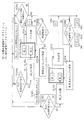
各生成部111は、図6に示すようにそれぞれ測位補強情報ストリーム703を生成し、出力する。
そして、例えば、測位補強情報ストリーム703aの生成にあたって、生成部111aは、図7のブロック1(B1)の各電子基準点702から電子基準点情報700を1秒ごとに受信する。
そして、生成部111aは、ブロック1(B1)内に定義された各グリッドの地域固有誤差604(対流圏遅延誤差と電離層遅延誤差との少なくともいずれか)を1秒ごとに生成する。ここで、図9の測位補強情報ストリーム703aの「B1」のグラフが測位補強情報ストリーム703aのうちの1秒ごとの地域固有誤差604のデータを示すものである。
なお、グリッドごとの対流圏遅延誤差、グリッドごとの電離層遅延誤差のデータの図示は省略し、例えば、図9の測位補強情報ストリーム703aに示すように、ブロック1のグリッドごとの対流圏遅延誤差と、グリッドごとの電離層遅延誤差との少なくともいずれかのデータを示すものとして単に「B1」と図示する(以降の説明においても同様である)。
(Examples of processing in the generation unit, the network synchronization unit, and the integration unit)
FIG. 9 is a diagram illustrating an example of an outline of processing performed by the generation unit, the inter-network synchronization unit, and the integration unit.
Each generation unit 111 generates and outputs a positioning reinforcement information stream 703 as shown in FIG.
For example, when generating the positioning
Then, the
In addition, illustration of the data of the troposphere delay error for every grid and the ionosphere delay error for every grid is abbreviate | omitted, for example, as shown in the positioning reinforcement | strengthening
更に、生成部111aは、各GPS衛星300の衛星クロック誤差を1秒ごとに生成する。ここで、図9の測位補強情報ストリーム703aの「δt」のグラフが測位補強情報ストリーム703aのうちの1秒ごとの衛星クロック誤差のデータを示すものである。
なお、GPS衛星300ごとの衛星クロック誤差の図示は省略し、例えば、図9の測位補強情報ストリーム703aに示すように、GPS衛星300ごとの衛星クロック誤差のデータを示すものとして単に「δt」と図示する(以降の説明においても同様である)。
Further, the
The illustration of the satellite clock error for each
また、生成部111aは、各GPS衛星300の衛星固有誤差603(衛星軌道誤差と周波数間バイアスとの少なくともいずれか)を1秒ごとに生成する。ここで、図9の測位補強情報ストリーム703aの「δS」のグラフが測位補強情報ストリーム703aのうちの1秒ごとの衛星固有誤差603のデータを示すものである。
同様に、例えば、図9の測位補強情報ストリーム703aに示すように、GPS衛星300ごとの衛星軌道誤差と周波数間バイアスとの少なくともいずれかのデータを示すものとして単に「δS」と図示する(以降の説明においても同様である)。
Further, the
Similarly, for example, as shown in the positioning
そして、生成部111aにより生成された1秒ごとの地域固有誤差604と衛星クロック誤差と衛星固有誤差603とのデータを測位補強情報ストリーム703a(図6、図9)と称する。
同様に生成部111bは、ブロック2(B2)に対して測位補強情報ストリーム703bを生成し、生成部111cは、ブロック3(B3)に対して測位補強情報ストリーム703cを生成する。
The data of the region
Similarly, the
網間同期部112は、各生成部111から生成された測位補強情報ストリーム703を入力し、各測位補強情報ストリーム703間の時刻の同期調整を行う。
そして、統合部113は、網間同期部112により時刻が同期された各測位補強情報ストリーム703を入力し、衛星クロック誤差(δt)と衛星固有誤差603(δS)とを統合する。ここで具体的には、統合部113は、測位補強情報ストリーム703a〜cのうちのいずれかの衛星クロック誤差(δt)と衛星固有誤差603(δS)とを選択してもよいし、測位補強情報ストリーム703a〜c間で衛星クロック誤差(δt)と衛星固有誤差603(δS)との平均値を算出してもよい。
The inter-network synchronization unit 112 receives the positioning reinforcement information stream 703 generated from each generation unit 111 and performs time synchronization adjustment between the positioning reinforcement information streams 703.
Then, the
そして、統合部113は、統合された衛星クロック誤差(δt)と衛星固有誤差603(δS)とを全網共通補強データストリーム704として出力する(図6、図9)。
また、統合部113は、測位補強情報ストリーム703aに含まれる地域固有誤差604a(B1)を固有補強データストリーム705aとして出力する(図6、図9)。そして、統合部113は、測位補強情報ストリーム703bに含まれる地域固有誤差604b(B2)を固有補強データストリーム705bとして出力し、測位補強情報ストリーム703cに含まれる地域固有誤差604c(B3)を固有補強データストリーム705cとして出力する(図6、図9)。
Then, the
Further, the
(周期調整部と空間圧縮_エンコード部とにおける処理の第1の例)
図10は、周期調整部と空間圧縮_エンコード部との処理の例を示すフローチャートである。
図11は、衛星軌道誤差のコンシステンシー算出の例を示す図である。
ここでは、第1の例として、コンシステンシー補正対象の誤差が衛星軌道誤差である場合を説明する。なお、コンシステンシー補正対象の誤差として、他には、周波数間バイアスや対流圏遅延誤差や電離層遅延誤差などが挙げられる。
(First Example of Processing in Period Adjustment Unit and Spatial Compression_Encoding Unit)
FIG. 10 is a flowchart illustrating an example of processing performed by the period adjustment unit and the space compression_encoding unit.
FIG. 11 is a diagram illustrating an example of calculating the consistency of the satellite orbit error.
Here, a case where the consistency correction target error is a satellite orbit error will be described as a first example. Other errors that are subject to consistency correction include inter-frequency bias, tropospheric delay error, ionospheric delay error, and the like.
<T=0における処理>
送信装置101における処理を時刻「T」に対応させて説明を進める。
まず、時刻「T=0」における処理を説明する。なお、時刻「T=0」において、送信装置101が処理を開始したものとする。
<Processing at T = 0>
The processing in the transmitting
First, the process at time “T = 0” will be described. It is assumed that the
共通周期調整部115は、全網共通補強データストリーム704の衛星クロック誤差(δt)と衛星固有誤差603(δS)との時間変化を1秒ごとに監視する(図10のS1001)。
網周期調整部116は、固有補強データストリーム705a〜cの地域固有誤差604(B1〜B3)の時間変化を1秒ごとに監視する(図10のS1001)。なお、網周期調整部116が監視を行う周期は1秒ごとに限定されるものではない。
The common
The network
そして、共通周期調整部115は、衛星クロック誤差送信タイミングであるか否かを判定する(図10のS1002)。
衛星クロック誤差送信タイミングでない場合(図10のS1002の「NO」)、共通周期調整部115と網周期調整部116とは、S1001の処理を行う。
Then, the common
When it is not the satellite clock error transmission timing (“NO” in S1002 of FIG. 10), the common
衛星クロック誤差送信タイミングは、図8に示す通り「T=0、10、20、30(以下省略)」であり、共通周期調整部115は、「T=0」が衛星クロック誤差送信タイミングであると判定する(図10のS1002の「YES」)。
As shown in FIG. 8, the satellite clock error transmission timing is “T = 0, 10, 20, 30 (hereinafter omitted)”, and the common
次に、共通周期調整部115は、コンシステンシー補正対象の誤差である衛星軌道誤差が送信済であるか否かを判定する(図10のS1003)。
なお、コンシステンシー補正が不要な場合は、図10におけるS1003〜S1004及びS1007の処理が省略され、前述の通り修正衛星クロック誤差602は、単に衛星クロック誤差(δt)となる。
Next, the common
When consistency correction is not required, the processing of S1003 to S1004 and S1007 in FIG. 10 is omitted, and the corrected
時刻「T=0」においては、送信装置101が衛星軌道誤差を未送信であるため、共通周期調整部115は、コンシステンシー補正対象の誤差が送信済でないと判定する(図10のS1003の「NO」)。
At time “T = 0”, since the transmitting
そして、共通周期調整部115は、「T=0」において送信対象の衛星クロック誤差605a(δt)にコンシステンシー606aを含めて修正衛星クロック誤差602sを生成する(図10のS1005、図11)。
ここで、「T=0」では、図10のS1004においてコンシステンシーが算出されていない為、コンシステンシー606a「C」の値はゼロとなる。したがって、修正衛星クロック誤差602s「δt+C」は、全網共通補強データストリーム704の「T=0」における衛星クロック誤差605a(δt)と同じになる(図11)。
Then, the common
Here, at “T = 0”, since the consistency is not calculated in S1004 of FIG. 10, the value of the
また、共通周期調整部115は、コンシステンシー補正対象の誤差である衛星軌道誤差の送信タイミングであるか否かを判定する(図10のS1006)。
衛星軌道誤差(衛星固有誤差603)の送信タイミングは、図8に示す通り「T=0、30(以下省略)」であり、共通周期調整部115は、「T=0」が衛星軌道誤差の送信タイミングであると判定する(図10のS1006の「YES」)。
Further, the common
The transmission timing of the satellite orbit error (satellite intrinsic error 603) is “T = 0, 30 (hereinafter omitted)” as shown in FIG. 8, and the common
共通周期調整部115は、送信対象である衛星軌道誤差を時間変化モニタ記憶部118に出力し、時間変化モニタ記憶部118は出力された送信対象である衛星軌道誤差を記憶する(図10のS1007)。
例えば、時間変化モニタ記憶部118は、「T=0」における衛星軌道誤差として、図11に示す「a1」を記憶する。
The common
For example, the time change
そして、空間圧縮_エンコード部117は、時刻「T=0」における修正衛星クロック誤差602s、衛星固有誤差603a、地域固有誤差604a「B1」を図8に示す通り、時刻タグ601a「T=0」に対応付けて送信する(図10のS1008)。ここで、空間圧縮_エンコード部117は、時刻タグ601a「T=0」、修正衛星クロック誤差602s、衛星固有誤差603a、地域固有誤差604a「B1」の順で送信する。
なお、時刻「T=0」における地域固有誤差604a「B1」は、網周期調整部116により固有補強データストリーム705aから抽出される。以降の処理において、地域固有誤差604b「B2」、地域固有誤差604c「B3」なども同様である。
Then, the spatial compression_encoding unit 117 displays the corrected
The local
<T=10における処理>
次に、共通周期調整部115は、「T=10」の時に衛星クロック誤差送信タイミングであると判定する(図10のS1002の「YES」)。
そして、時刻「T=10」においては、衛星軌道誤差を送信済であるため(図10のS1003の「YES」)、共通周期調整部115は、衛星軌道誤差のコンシステンシーを算出する(図10のS1004)。
<Processing at T = 10>
Next, the common
Since the satellite orbit error has already been transmitted at time “T = 10” (“YES” in S1003 in FIG. 10), the common
具体的には、図11に示す通り、共通周期調整部115は、時間変化モニタ記憶部118に記憶されている衛星軌道誤差「a1」と「T=10」の時の衛星軌道誤差「a2」との差をコンシステンシー606bとして算出する。
すなわち、共通周期調整部115は、衛星クロック誤差送信タイミングの到来時に、送信済みの衛星軌道誤差と、衛星クロック誤差送信タイミングの到来時の衛星軌道誤差との差をコンシステンシー606として算出する。なお、コンシステンシー606は、修正衛星クロック誤差602以外の誤差である他要因誤差の変動量、すなわち他要因誤差変動量に対応する。
Specifically, as shown in FIG. 11, the common
That is, the common
ここで、図11は、特定のGPS衛星300の衛星軌道誤差を示す例である。衛星軌道誤差は、GPS衛星300ごとに示されるので、共通周期調整部115は、GPS衛星300ごとに衛星軌道誤差のコンシステンシーを算出する。
Here, FIG. 11 is an example showing a satellite orbit error of a
そして、共通周期調整部115は、「T=10」において送信対象の衛星クロック誤差605b(δt)に算出したコンシステンシー606bを含めて修正衛星クロック誤差602tを生成する(図10のS1005、図11)。
ここで、前述の通り、衛星軌道誤差のコンシステンシーはGPS衛星300ごとに算出されている。そして、共通周期調整部115は、GPS衛星300ごとの衛星クロック誤差605(δt)に対応させて、GPS衛星300ごとの衛星軌道誤差のコンシステンシーを含めて、GPS衛星300ごとの修正衛星クロック誤差602を生成する。
一方、時刻「T=10」は、衛星軌道誤差の送信タイミングではないので(図10のS06の「NO」)、図10のS1007の処理は省略される。
Then, the common
Here, as described above, the satellite orbit error consistency is calculated for each
On the other hand, since the time “T = 10” is not the transmission timing of the satellite orbit error (“NO” in S06 in FIG. 10), the processing in S1007 in FIG. 10 is omitted.
そして、空間圧縮_エンコード部117は、時刻「T=10」における修正衛星クロック誤差602t、地域固有誤差604b「B2」を図8に示す通り、時刻タグ601b「T=10」に対応付けて送信する(図10のS1008)。ここで、空間圧縮_エンコード部117は、時刻タグ601b「T=10」、修正衛星クロック誤差602t、地域固有誤差604b「B2」の順で送信する。
すなわち、空間圧縮_エンコード部117は、共通周期調整部115によりコンシステンシー606bが含められた衛星クロック誤差605bである修正衛星クロック誤差602tを送信する。
なお、時刻「T=10」においては、前述の通り衛星軌道誤差は送信されない。
Then, the spatial compression_encoding unit 117 transmits the corrected
That is, the spatial compression_encoding unit 117 transmits the corrected
At time “T = 10”, the satellite orbit error is not transmitted as described above.
時刻「T=20」における処理は、時刻「T=10」における処理と同様であるため、説明を省略する。 The process at time “T = 20” is the same as the process at time “T = 10”, and thus the description thereof is omitted.
<T=30における処理>
共通周期調整部115は、「T=30」においても衛星クロック誤差送信タイミングであると判定する(図10のS1002の「YES」)。
そして、共通周期調整部115は、図10のS1003〜S1005までは、前述の時刻「T=10」の処理と同様の処理を行う。
<Processing at T = 30>
The common
Then, the common
一方、「T=30」は、衛星軌道誤差の送信タイミングなので(図10のS1006の「YES」)、共通周期調整部115は、送信対象の衛星軌道誤差「a4」(図11)を出力し、時間変化モニタ記憶部118はその値を記憶する(図10のS1007)。
On the other hand, since “T = 30” is the transmission timing of the satellite orbit error (“YES” in S1006 in FIG. 10), the common
そして、空間圧縮_エンコード部117は、時刻「T=30」における修正衛星クロック誤差602v、衛星固有誤差603d、地域固有誤差604d「B1」を図8に示す通り、時刻タグ601d「T=30」に対応付けて送信する(図10のS1008)。
Then, the spatial compression_encoding unit 117 shows the corrected
すなわち、空間圧縮_エンコード部117は、図8に示すとおり、時刻「T=0」にて衛星軌道誤差(衛星固有誤差603a)を送信した後に、複数回の衛星クロック誤差送信タイミングにおいて複数の修正衛星クロック誤差602t〜vを送信する。更に、空間圧縮_エンコード部117は、複数の修正衛星クロック誤差602t〜vの送信後に、時刻「T=30」にて新たな衛星軌道誤差(衛星固有誤差603d)を送信する。そして、図8の図示は省略するが、空間圧縮_エンコード部117は、時刻「T=60」以降も送信処理を繰り返す。
That is, as shown in FIG. 8, the spatial compression_encoding unit 117 transmits a plurality of corrections at a plurality of times of satellite clock error transmission after transmitting a satellite orbit error (satellite
<T=40における処理>
図10のS1002〜S1003については、T=10〜30における処理と同様であるため説明を省略する。
共通周期調整部115は、「T=40」において、時間変化モニタ記憶部118に記憶されている衛星軌道誤差「a4」と「T=40」の時の衛星軌道誤差「a5」との差をコンシステンシー606eとして算出する(図11、図10のS1004)。
すなわち、共通周期調整部115は、衛星クロック誤差送信タイミングの到来時に、空間圧縮_エンコード部117により最後に送信された衛星軌道誤差「a4」と、衛星クロック誤差送信タイミングの到来時の衛星軌道誤差「a5」との差をコンシステンシー606eとして算出する。
以降の処理については、前述と同様であるため、説明を省略する。
<Processing at T = 40>
Since S1002 to S1003 in FIG. 10 are the same as the processing at T = 10 to 30, description thereof will be omitted.
The common
That is, the common
Since the subsequent processing is the same as described above, description thereof is omitted.
また、コンシステンシー補正対象の誤差が周波数間バイアスである場合も、衛星軌道誤差が周波数間バイアスに置き換えられるだけで、周期調整部と空間圧縮_エンコード部とにおける処理の第1の例と同様であるため、説明を省略する。 Further, when the error to be corrected for consistency is an inter-frequency bias, the satellite orbit error is simply replaced with the inter-frequency bias, and the same processing as that in the first example of the process in the period adjustment unit and the spatial compression_encoding unit is performed. Therefore, the description is omitted.
(周期調整部と空間圧縮_エンコード部とにおける処理の第2の例)
図12は、対流圏遅延誤差のコンシステンシー算出の例を示す図である。
図13は、ブロックごとの修正衛星クロック誤差の例を示す図である。
ここでは、第2の例として、コンシステンシー補正対象の誤差がブロックごとの対流圏遅延誤差である場合を説明する。
そして、測位用補正データ600の例は図8を用い、周期調整部と空間圧縮_エンコード部との処理の例は図10のフローチャートを用いて説明する。
(Second Example of Processing in Period Adjustment Unit and Spatial Compression_Encoding Unit)
FIG. 12 is a diagram illustrating an example of calculating a tropospheric delay error consistency.
FIG. 13 is a diagram illustrating an example of the corrected satellite clock error for each block.
Here, as a second example, a case will be described in which the consistency correction target error is a tropospheric delay error for each block.
An example of the
図8に示す通り、空間圧縮_エンコード部117は、複数のブロックに対する複数の地域固有誤差604を所定の送信順序に従って送信する。ここで、所定の順序とは、例えば、図8に示す通り、ブロック1(B1)、ブロック2(B2)、ブロック3(B3)の順序である。
また、ブロックがN個であった場合、所定の順序は、N!通りの順列のうちのいずれかであってもよい。すなわち、1つのデータフレーム内に全ブロックの地域固有誤差604が配置されればよい。
更に、空間圧縮_エンコード部117は、地域固有誤差604の送信の合間に到来する衛星クロック誤差送信タイミングにおいて修正衛星クロック誤差602を送信している。
As shown in FIG. 8, the spatial compression_encoding unit 117 transmits a plurality of region-
When there are N blocks, the predetermined order is N! It may be one of the street permutations. That is, the region
Furthermore, the spatial compression_encoding unit 117 transmits the corrected
<T=0における処理>
まず、時刻「T=0」における処理を説明する。なお、時刻「T=0」において、送信装置101が処理を開始したものとする。
<Processing at T = 0>
First, the process at time “T = 0” will be described. It is assumed that the
前述の第1の例と同様に、共通周期調整部115は、全網共通補強データストリーム704の衛星クロック誤差(δt)と衛星固有誤差603(δS)との時間変化を1秒ごとに監視する(図10のS1001)。
網周期調整部116は、固有補強データストリーム705a〜cの地域固有誤差604(B1〜B3)の時間変化を1秒ごとに監視する(図10のS1001)。すなわち、網周期調整部116は、ブロックごとに地域固有誤差604(B1〜B3)の時間変化を1秒ごとに監視する。
Similar to the first example described above, the common
The network
ここで、前述の通り、1つのブロックの地域固有誤差604(例えば対流圏遅延誤差)には、当該ブロック内の複数のグリッドごとの地域固有誤差604(例えば対流圏遅延誤差)が含まれる。
そして、網周期調整部116は、コンシステンシーの算出にあたって、ブロック内の複数のグリッドの地域固有誤差604(例えば対流圏遅延誤差)の平均値を算出し、算出した平均値を当該ブロックの地域固有誤差604(例えば対流圏遅延誤差)として監視してもよい。その場合、例えば対流圏遅延誤差のコンシステンシーとしては、1つのブロックに対して、1つの値が算出される。
一方、網周期調整部116は、コンシステンシーの算出にあたって、ブロック内の複数のグリッドの地域固有誤差604(例えば対流圏遅延誤差)を監視してもよい。その場合、例えば対流圏遅延誤差のコンシステンシーとしては、1つのブロックに対して、複数のグリッドごとの値が算出される。そして、衛星クロック誤差605もグリッドごとに生成されることとなる。
ここでは、網周期調整部116が、前者のように、コンシステンシーの算出にあたって、ブロック内の複数のグリッドの地域固有誤差604(例えば対流圏遅延誤差)の平均値を算出する場合を例に説明を進める。
Here, as described above, the region-specific error 604 (for example, troposphere delay error) of one block includes the region-specific error 604 (for example, troposphere delay error) for each of a plurality of grids in the block.
Then, in calculating the consistency, the network
On the other hand, the network
Here, the case where the network
そして、網周期調整部116は、図8に示す通り「T=0、10、20、30(以下省略)」の時刻において、衛星クロック誤差送信タイミングであると判定する(図10のS1002の「YES」)。
なお、第1の例と同様に、図10のS1002において、共通周期調整部115が衛星クロック誤差送信タイミングを判定してもよい。
Then, as shown in FIG. 8, the network
As in the first example, the common
次に網周期調整部116は、「T=0」において、コンシステンシー補正対象の誤差であるブロックごとの対流圏遅延誤差がいずれも送信済でないと判定し(図10のS1003の「NO」)、図10のS1004の処理を省略する。
また、共通周期調整部115は、網周期調整部116が算出したブロックごとの対流圏遅延誤差のコンシステンシー606「C1〜C3」を入力するが、ここでは、いずれも算出されないので、コンシステンシー606「C1〜C3」はいずれもゼロとなる。
Next, at “T = 0”, the network
Further, the common
そして、共通周期調整部115は、「T=0」における衛星クロック誤差605(δt)に対し、ブロックごとにコンシステンシー606を含め、ブロックごとの修正衛星クロック誤差602を生成する(図10のS1005)。
ここでは、コンシステンシー606「C1〜C3」はいずれもゼロなので、修正衛星クロック誤差602は、「T=0」における衛星クロック誤差605(δt)と同じになる。
Then, the common
Here, since the
次に網周期調整部116は、コンシステンシー補正対象の誤差であるブロック1(B1)の対流圏遅延誤差(地域固有誤差604)の送信タイミングであると判定する(図10のS1006の「YES」)。
Next, the network
網周期調整部116は、送信対象であるブロック1(B1)の対流圏遅延誤差を出力し、時間変化モニタ記憶部118はその値を記憶する(図10のS1007)。
例えば、時間変化モニタ記憶部118は、「T=0」におけるブロック1(B1)の対流圏遅延誤差として、図12に示す「b1」を記憶する。
The network
For example, the time change
そして、空間圧縮_エンコード部117は、時刻「T=0」における修正衛星クロック誤差602s、衛星固有誤差603a、地域固有誤差604a「B1」を図8に示す通り、時刻タグ601a「T=0」に対応付けて送信する(図10のS1008)。ここで、空間圧縮_エンコード部117は、時刻タグ601a「T=0」、修正衛星クロック誤差602s、衛星固有誤差603a、地域固有誤差604a「B1」の順で送信する。
なお、時刻「T=0」における衛星固有誤差603aは、共通周期調整部115により全網共通補強データストリーム704から抽出される。また、時刻「T=0」における地域固有誤差604a「B1」は、網周期調整部116により固有補強データストリーム705aから抽出される。以降の処理においても同様である。
Then, the spatial compression_encoding unit 117 displays the corrected
The satellite
ここで、修正衛星クロック誤差602sには、ブロック(B1〜B3)ごとの修正衛星クロック誤差602が含まれる。
図13に、ブロック(B1〜B3)ごとの修正衛星クロック誤差602の例を示す。
例えば、「δt+C1」がブロック1(B1)の修正衛星クロック誤差602である。 すなわち、空間圧縮_エンコード部117は、全ブロック分の修正衛星クロック誤差602を衛星クロック誤差送信タイミングごとに送信する。
Here, the corrected
FIG. 13 shows an example of the corrected
For example, “δt + C1” is the corrected
<T=10における処理>
以降の説明において、図10のS1001とS1002との処理の説明は省略する。
網周期調整部116は、「T=10」において、コンシステンシー補正対象の誤差であるブロック1(B1)の対流圏遅延誤差は送信済であると判定する(図10のS1003の「YES」)。一方、網周期調整部116は、「T=10」において、コンシステンシー補正対象の誤差であるブロック2(B2)とブロック3(B3)との対流圏遅延誤差は送信済でないと判定する(図10のS1003の「NO」)。
<Processing at T = 10>
In the following description, the description of the processing of S1001 and S1002 in FIG. 10 is omitted.
The network
よって、網周期調整部116は、ブロック1(B1)の対流圏遅延誤差に対してのみコンシステンシー606を算出する(図10のS1004)。
具体的には、図12に示す通り、網周期調整部116は、時間変化モニタ記憶部118に記憶されているブロック1(B1)の対流圏遅延誤差「b1」と「T=10」の時のブロック1(B1)の対流圏遅延誤差「b2」との差をコンシステンシー606a「C1」として算出する。
Therefore, the network
Specifically, as shown in FIG. 12, the network
次に、共通周期調整部115は、網周期調整部116が算出したブロック1(B1)の対流圏遅延誤差のコンシステンシー606a「C1」を入力する。
そして、共通周期調整部115は、ブロック1(B1)に対しては、「T=10」において送信対象の衛星クロック誤差605(δt)に算出したコンシステンシー606a「C1」を含めて修正衛星クロック誤差602「δt+C1」を生成する(図10のS1005)。
一方、ブロック2(B2)とブロック3(B3)とに対しては、コンシステンシー606が算出されていないので、共通周期調整部115は、T=0における処理と同様の処理を行う。
Next, the common
Then, for the block 1 (B1), the common
On the other hand, for block 2 (B2) and block 3 (B3), since
また、時刻「T=10」は、コンシステンシー補正対象の誤差であるブロック2(B2)の対流圏遅延誤差(地域固有誤差604)の送信タイミングである(図10のS1006の「YES」)。そのため、時間変化モニタ記憶部118は、「T=10」におけるブロック2(B2)の対流圏遅延誤差として、「d2」を記憶する(図12、図10のS1007)。
図10のS1008の処理については説明を省略する。
The time “T = 10” is the transmission timing of the tropospheric delay error (region-specific error 604) of the block 2 (B2), which is the consistency correction target error (“YES” in S1006 in FIG. 10). Therefore, the time change
Description of the processing of S1008 in FIG. 10 is omitted.
<T=20における処理>
網周期調整部116は、「T=20」において、コンシステンシー補正対象の誤差であるブロック1(B1)とブロック2(B2)の対流圏遅延誤差は送信済であると判定する(図10のS1003の「YES」)。一方、網周期調整部116は、「T=20」において、コンシステンシー補正対象の誤差であるブロック3(B3)の対流圏遅延誤差は送信済でないと判定する(図10のS1003の「NO」)。
<Processing at T = 20>
The network
よって、網周期調整部116は、ブロック1(B1)の対流圏遅延誤差に対して、図12に示す通り、時間変化モニタ記憶部118に記憶されているブロック1(B1)の対流圏遅延誤差「b1」と「T=20」の時のブロック1(B1)の対流圏遅延誤差「b3」との差をコンシステンシー606b「C1」として算出する。
また、網周期調整部116は、ブロック2(B2)の対流圏遅延誤差に対して、図12に示す通り、時間変化モニタ記憶部118に記憶されているブロック2(B2)の対流圏遅延誤差「d2」と「T=20」の時のブロック2(B2)の対流圏遅延誤差「d3」との差をコンシステンシー606c「C2」として算出する。
Therefore, the network
Further, as shown in FIG. 12, the network
すなわち、網周期調整部116は、衛星クロック誤差送信タイミングの到来時に、ブロックごとに、送信済みの対流圏遅延誤差と、衛星クロック誤差送信タイミングの到来時の対流圏遅延誤差との差をコンシステンシー606として算出する。
That is, the network
次に、共通周期調整部115は、網周期調整部116が算出したコンシステンシー606b「C1」とコンシステンシー606c「C2」とを入力する。
そして、共通周期調整部115は、ブロック1(B1)に対しては、「T=20」において送信対象の衛星クロック誤差605(δt)に算出したコンシステンシー606b「C1」を含めて修正衛星クロック誤差602「δt+C1」を生成する(図10のS1005)。
同様に、共通周期調整部115は、ブロック2(B2)に対しては、「T=20」において送信対象の衛星クロック誤差605(δt)に算出したコンシステンシー606c「C2」を含めて修正衛星クロック誤差602「δt+C2」を生成する(図10のS1005)。
Next, the common
Then, for the block 1 (B1), the common
Similarly, for the block 2 (B2), the common
すなわち、共通周期調整部115は、送信対象の衛星クロック誤差605にブロックごとのコンシステンシー606を含めて、ブロックごとの修正衛星クロック誤差602を生成する。
一方、ブロック3(B3)に対しては、コンシステンシー606が算出されていないので、共通周期調整部115は、T=0における処理と同様の処理を行う。
That is, the common
On the other hand, for block 3 (B3), since
また、時刻「T=20」は、コンシステンシー補正対象の誤差であるブロック3(B3)の対流圏遅延誤差(地域固有誤差604)の送信タイミングである(図10のS1006の「YES」)。そのため、時間変化モニタ記憶部118は、「T=20」におけるブロック3(B3)の対流圏遅延誤差として、「e3」を記憶する(図12、図10のS1007)。
図10のS1008の処理については説明を省略する。
The time “T = 20” is the transmission timing of the tropospheric delay error (region-specific error 604) of the block 3 (B3), which is the consistency correction target error (“YES” in S1006 in FIG. 10). Therefore, the time change
Description of the processing of S1008 in FIG. 10 is omitted.
<T=30における処理>
図8に示す通り、空間圧縮_エンコード部117は、複数のブロックに対する複数の地域固有誤差604の送信が時刻T=0〜20までに完了すると、例えばT=30〜50に示されるように、各ブロックの新たな地域固有誤差604を前述の送信順序に従って送信する動作を繰り返す。
<Processing at T = 30>
As shown in FIG. 8, when the transmission of the plurality of region-
網周期調整部116は、ブロック1(B1)の対流圏遅延誤差に対して、図12に示す通り、時間変化モニタ記憶部118に記憶されているブロック1(B1)の対流圏遅延誤差「b1」と「T=30」の時のブロック1(B1)の対流圏遅延誤差「b4」との差をコンシステンシー606d「C1」として算出する(図10のS1004)。
また、網周期調整部116は、ブロック2(B2)の対流圏遅延誤差に対して、図12に示す通り、時間変化モニタ記憶部118に記憶されているブロック2(B2)の対流圏遅延誤差「d2」と「T=30」の時のブロック2(B2)の対流圏遅延誤差「d4」との差をコンシステンシー606e「C2」として算出する。
また、網周期調整部116は、ブロック3(B3)の対流圏遅延誤差に対して、図12に示す通り、時間変化モニタ記憶部118に記憶されているブロック3(B3)の対流圏遅延誤差「e3」と「T=30」の時のブロック3(B3)の対流圏遅延誤差「e4」との差をコンシステンシー606f「C3」として算出する。
また、時刻「T=30」は、前述の通り、ブロック1(B1)の対流圏遅延誤差(地域固有誤差604)を新たに送信するタイミングなので(図10のS1006の「YES」)、時間変化モニタ記憶部118は、送信対象のブロック1(B1)の対流圏遅延誤差「b4」を記憶する(図10のS1007)。
なお、図10のS1001〜S1003及びS1005及びS1008の説明は省略する。
As shown in FIG. 12, the network
Further, as shown in FIG. 12, the network
Further, as shown in FIG. 12, the network
Further, as described above, the time “T = 30” is the timing for newly transmitting the tropospheric delay error (region-specific error 604) of block 1 (B1) (“YES” in S1006 in FIG. 10). The
Note that descriptions of S1001 to S1003, S1005, and S1008 in FIG. 10 are omitted.
<T=40における処理>
網周期調整部116は、ブロック1(B1)の対流圏遅延誤差に対して、図12に示す通り、T=30の処理にて新たに時間変化モニタ記憶部118に記憶されたブロック1(B1)の対流圏遅延誤差「b4」と「T=40」の時のブロック1(B1)の対流圏遅延誤差「b5」との差をコンシステンシー606g「C1」として算出する(図10のS1004)。
コンシステンシー606h「C2」とコンシステンシー606i「C3」との説明は省略する。
<Processing at T = 40>
As shown in FIG. 12, the network
A description of the
すなわち、網周期調整部116は、衛星クロック誤差送信タイミングの到来時に、ブロックごとに、空間圧縮_エンコード部117により最後に送信された対流圏遅延誤差と、衛星クロック誤差送信タイミングの到来時の対流圏遅延誤差との差をコンシステンシー606として算出する。
そして、空間圧縮_エンコード部117は、前述の通り、図13に示すようなブロックごとの修正衛星クロック誤差602を送信する。
なお、図10のS1003及び、以降の処理については、前述と同様であるため、説明を省略する。
なお、空間圧縮_エンコード部117は、ブロックごとのコンシステンシー606を用いて複数のブロック全体(例えば日本全国)に共通して用いられるコンシステンシー606を算出してもよい。複数のブロック全体(例えば日本全国)に共通して用いられるコンシステンシー606は、例えば、ブロックごとのコンシステンシー606を用いてブロック全体の平均を算出することにより求められてもよい。
そして、複数のブロック全体に共通して用いられるコンシステンシー606が算出された場合は、修正衛星クロック誤差602はブロックごとに区別されず、複数のブロック全体(例えば日本全国)に共通する修正衛星クロック誤差602となる。
なお、空間圧縮_エンコード部117は、ブロックごとの修正衛星クロック誤差602の生成後に、ブロックごとの修正衛星クロック誤差602を用いて(例えばブロックごとの修正衛星クロック誤差602の平均値を算出して)、複数のブロック全体(例えば日本全国)に共通する修正衛星クロック誤差602を生成してもよい。
That is, the network
Then, as described above, the spatial compression_encoding unit 117 transmits the corrected
Note that S1003 in FIG. 10 and the subsequent processing are the same as described above, and thus description thereof is omitted.
Note that the spatial compression_encoding unit 117 may calculate a
When the
The spatial compression_encoding unit 117 uses the corrected
(周期調整部と空間圧縮_エンコード部とにおける処理の第3の例)
図14は、複数種類のコンシステンシーが含まれた修正衛星クロック誤差の第1の例を示す図である。
図15は、複数種類のコンシステンシーが含まれた修正衛星クロック誤差の第2の例を示す図である。
前述の第1の例では、コンシステンシー補正対象の誤差が衛星軌道誤差である場合を説明し、第2の例では、コンシステンシー補正対象の誤差がブロックごとの対流圏遅延誤差である場合を説明した。
しかし、コンシステンシー補正対象の誤差は複数種類であってもよい。
(Third example of processing in cycle adjustment unit and spatial compression_encoding unit)
FIG. 14 is a diagram illustrating a first example of a corrected satellite clock error including a plurality of types of consistency.
FIG. 15 is a diagram illustrating a second example of the corrected satellite clock error including a plurality of types of consistency.
In the first example described above, the case where the consistency correction target error is a satellite orbit error is described, and in the second example, the case where the consistency correction target error is a tropospheric delay error for each block is described. .
However, there may be a plurality of types of consistency correction errors.
例えば、衛星固有誤差603に衛星軌道誤差と周波数間バイアスとが含まれた衛星固有誤差603が空間圧縮_エンコード部117により送信され、衛星軌道誤差と周波数間バイアスとの両方がコンシステンシー補正対象とされる場合を想定する。
その場合、共通周期調整部115は衛星軌道誤差のコンシステンシー606(C’)と周波数間バイアスのコンシステンシー606(C’’)とを算出する。
そして、共通周期調整部115は、図14の例のように、衛星軌道誤差のコンシステンシー606(C’)と周波数間バイアスのコンシステンシー606(C’’)とを衛星クロック誤差605(δt)に含めた修正衛星クロック誤差602を生成する。
この場合、共通周期調整部115により生成された修正衛星クロック誤差602はブロックによって値が変わらないが、ブロックごとに修正衛星クロック誤差602が生成されてもよい。
For example, the satellite
In this case, the common
Then, as shown in the example of FIG. 14, the common
In this case, the value of the corrected
また、例えば、衛星軌道誤差とブロックごとの対流圏遅延誤差とがコンシステンシー補正対象とされる場合を想定する。
その場合、共通周期調整部115は衛星軌道誤差のコンシステンシー606(C’)を算出する。そして、網周期調整部116は、ブロックごとの対流圏遅延誤差のコンシステンシー606(C1〜C3)を算出する。
そして、共通周期調整部115は、図15の例のように、ブロックごとの修正衛星クロック誤差602を生成する。
例えば、共通周期調整部115は、ブロック1の対流圏遅延誤差のコンシステンシー606(C1)と、衛星軌道誤差のコンシステンシー606(C’)とを衛星クロック誤差605(δt)に含めて、ブロック1(B1)の修正衛星クロック誤差602(δt+C1+C’)を生成する。
Further, for example, a case is assumed in which satellite orbit errors and tropospheric delay errors for each block are subject to consistency correction.
In this case, the common
Then, the common
For example, the common
また、衛星軌道誤差と周波数間バイアスとブロックごとの対流圏遅延誤差とがコンシステンシー補正対象とされる場合を想定する。この場合、図示は省略するが、例えば、共通周期調整部115は、ブロック1の対流圏遅延誤差のコンシステンシー606(C1)と、衛星軌道誤差のコンシステンシー606(C’)と周波数間バイアスのコンシステンシー606(C’’)とを衛星クロック誤差605(δt)に含めて、ブロック1(B1)の修正衛星クロック誤差602(δt+C1+C’+C’’)を生成する。
Further, it is assumed that the satellite orbit error, the inter-frequency bias, and the tropospheric delay error for each block are subject to consistency correction. In this case, although not shown in the figure, for example, the common
(5)測位装置の説明
ここから、測位装置201の説明を行う。
(5) Description of positioning device From here, the
(測位装置の構成)
図16は、測位装置の構成の例を示す図である。
測位装置201は、測位情報受信部800、デコード部801、補強情報伸張部802、測位計算部804、記憶部805を備える。
デコード部801は、受信部とデータファイル生成部と測位部とに対応し、測位計算部804は、測位部に対応する。
(Configuration of positioning device)
FIG. 16 is a diagram illustrating an example of the configuration of the positioning device.
The
The
測位情報受信部800は、各GPS衛星300から測位情報701を受信する。なお、測位情報701には、時刻ごとの情報が示されている。
デコード部801は、準天頂衛星400から測位用補正データ600を受信する。ここで、デコード部801は、例えば図8に示すように、「時刻タグ601a、修正衛星クロック誤差602s、衛星固有誤差603a、地域固有誤差604a、時刻タグ601b、(以下省略)」の順番で測位用補正データ600内のデータを受信する。
なお、デコード部801が受信する測位用補正データ600は、前述の通り、送信装置101により送信された測位用補正データ600を準天頂衛星400が受信して、測位装置201に転送したものである。
The positioning
The
As described above, the
ここで、測位装置201は、単独測位により当該測位装置201が所在するブロックを特定することが可能である。なお、単独測位の方法は既存の技術によるものであり、説明を省略する。
そして、デコード部801は、測位装置201が所在するブロックにおける衛星測位に必要な誤差情報を時刻タグ601が示す時刻ごとに抽出する。
ここで、誤差情報とは、修正衛星クロック誤差602や、衛星固有誤差603や、地域固有誤差604などである。
Here, the
Then, the
Here, the error information includes a corrected
補強情報伸張部802は、デコード部801が抽出した時刻ごとの誤差から、衛星測位の補正量を時刻ごとに算出する。
測位計算部804は、補強情報伸張部802により算出された時刻ごとの補正量と、測位情報受信部800により受信された時刻ごとの測位情報701とから、所定の時刻における衛星測位を実施する。
The reinforcement
The
なお、デコード部801は、抽出した誤差情報を用いて所定の記述形式のデータファイルを生成し、外部に出力してもよい。ここで、所定の記述形式とは例えば衛星測位システムにおける国際標準フォーマットRTCM−104などである。
そして、出力されたデータファイルは他の測位装置に利用されてもよい。
Note that the
The output data file may be used for other positioning devices.
(ブロック1(B1)に所在する測位装置201における処理)
図17は、デコード部の処理の例を示すフローチャートである。
図18は、測位用補正データの受信の例を示す図である。
ここで、図18の測位用補正データ600の例を用いて、デコード部801の処理の詳細を説明する。
なお、図18は、修正衛星クロック誤差602が図13のようにブロックごとになっている例である。そして、図8の修正衛星クロック誤差602sが図18の修正衛星クロック誤差602a〜cに対応し、図8の修正衛星クロック誤差602tが図18の修正衛星クロック誤差602d〜fに対応する(他の修正衛星クロック誤差602も同様)。
すなわち、デコード部801は、図18に示すように、ブロックごとの修正衛星クロック誤差602と、ブロックごとの地域固有誤差604とを受信する。
そして、測位装置201が、ブロック1(B1)に所在している場合を説明する。
(Processing in
FIG. 17 is a flowchart illustrating an example of processing of the decoding unit.
FIG. 18 is a diagram illustrating an example of receiving positioning correction data.
Here, the details of the processing of the
FIG. 18 shows an example in which the corrected
That is, as shown in FIG. 18, the
And the case where the
<t=0〜10における処理>
測位装置201における処理を時刻「t」に対応させて説明を進める。なお、時刻「t」は、送信装置101の処理で説明した時刻「T」とは所定の時間(例えば、測位用補正データ600が送信装置101から測位装置201に到達する時間)変位していてもよい。
デコード部801は、前述の通り、測位装置201が測位用補正データ600内の誤差を送信した順番と同じ順番で、測位用補正データ600内の誤差を受信する(図17のS1701)。
<Processing at t = 0 to 10>
The processing in the
As described above, the
なお、測位用補正データ600内の誤差の送信順序及び送信タイミングは予め決められており、当該送信順序と送信タイミングとを測位装置201が所定の記憶領域に記憶していてもよいし、測位用補正データ600に測位用補正データ600内の誤差の送信順序と送信タイミングとを示す情報が付与されていてもよい。いずれにしても、測位装置201は、測位用補正データ600内の誤差の送信順序と送信タイミングとを特定することが可能である。
Note that the transmission order and transmission timing of errors in the
そして、デコード部801は、現在のタイミングが時刻タグ601の受信タイミングか否かを判定する(図17のS1702)。
時刻「t=0」において、デコード部801は、時刻タグ601a(図18)の受信タイミングと判定し(図17のS1702の「YES」)、受信した時刻タグ601aを出力し、記憶部805はその時刻タグ601aを記憶する(図17のS1710)。
なお、デコード部801は、時刻タグ601の受信に2秒間要するものとする(以降の説明も同様)。
Then, the
At time “t = 0”, the
Note that the
次に、時刻「t=2」において、S1701〜S1702を経て、デコード部801は、修正衛星クロック誤差602a〜cの受信タイミングと判定する(図17のS1703の「YES」)。
Next, at time “t = 2”, through S1701 to S1702, the
そして、デコード部801は記憶部805に衛星固有誤差603と地域固有誤差604とが記憶されているか否かを判定する(図17のS1711)。
この時点では、いずれも記憶部805に記憶されていないので(図17のS1711の「NO」)、デコード部801は受信した修正衛星クロック誤差602a〜cのうち、ブロック1(B1)の修正衛星クロック誤差602aを出力し、記憶部805はその修正衛星クロック誤差602aを記憶する(図17のS1713)。
ここで、記憶部805は、修正衛星クロック誤差602a〜cを記憶してもよい。
なお、デコード部801は、修正衛星クロック誤差602の受信に4秒間要するものとする(以降の説明も同様)。
なお、デコード部801が複数のブロック全体(例えば日本全国)で共通の修正衛星クロック誤差602を受信した場合、記憶部は、ブロック間(ブロック全体)で共通の修正衛星クロック誤差602を記憶する(以下同様)。
Then, the
At this time, none of them is stored in the storage unit 805 (“NO” in S1711 of FIG. 17), so the
Here, the
It is assumed that the
When the
次に、時刻「t=6」において、デコード部801は、S1701〜S1703を経て、衛星固有誤差603aの受信タイミングと判定する(図17のS1704の「YES」)。
デコード部801は、受信した衛星固有誤差603aを出力し、記憶部805はその衛星固有誤差603aを記憶する(図17のS1708)。
なお、デコード部801は、衛星固有誤差603の受信に2秒間要するものとする(以降の説明も同様)。
Next, at time “t = 6”, the
The
It is assumed that the
次に時刻「t=8」において、デコード部801は、S1701〜S1704を経て、所在ブロックであるブロック1(B1)の地域固有誤差604aの受信タイミングと判定する(図17のS1705の「YES」)。
デコード部801は、地域固有誤差604の最初の受信か否かを判定する(図17のS1706)。
この時点では、地域固有誤差604の最初の受信であるため(図17のS1706の「YES」、デコード部801は、受信した地域固有誤差604aと、記憶部805に記憶されている時刻タグ601aと修正衛星クロック誤差602aと衛星固有誤差603aとを補強情報伸張部802に出力する(図17のS1707)。
なお、デコード部801は、データフレーム内の最初のデータセットの地域固有誤差604(例えば地域固有誤差604aや地域固有誤差604d)の受信に2秒間要するものとする。そして、デコード部801は、データフレーム内の他のデータセットの地域固有誤差604(例えば、地域固有誤差604b〜c、地域固有誤差604e〜f)の受信に4秒間要するものとする。
Next, at time “t = 8”, the
The
At this time, since it is the first reception of the region-specific error 604 (“YES” in S1706 in FIG. 17), the
Note that the
補強情報伸張部802は出力された地域固有誤差604aと時刻タグ601aと修正衛星クロック誤差602aと衛星固有誤差603aとにより、時刻タグ601aに示された時刻における補正量を算出する。そして、前述の通り、測位計算部804は、算出された補正量を用いて衛星測位を行う。すなわち、測位計算部804は時刻「t=10」において1回目の衛星測位を行う(図18)。
一方、デコード部801は、受信した地域固有誤差604aを記憶部805にも出力し、記憶部805はその地域固有誤差604aを記憶する(図17のS1709)。
The reinforcement
On the other hand, the
ここで、地域固有誤差604aは、測位装置201の所在するブロック1(B1)の地域固有誤差604であり、修正衛星クロック誤差602aは、同様に測位装置201の所在するブロック1(B1)の修正衛星クロック誤差602である。
すなわち、測位計算部804は、測位装置201の所在するブロックの地域固有誤差604と、測位装置201の所在するブロックの修正衛星クロック誤差602とを用いて衛星測位を行う。
なお、デコード部801が複数のブロック全体(例えば日本全国)で共通の修正衛星クロック誤差602を受信した場合、測位計算部804は、測位装置201の所在するブロックの地域固有誤差604と、ブロック間(ブロック全体)で共通の修正衛星クロック誤差602とを用いて衛星測位を行う(以下同様)。
Here, the region-
That is, the
When the
<t=10〜20における処理>
次に、時刻「t=10」において、デコード部801は、時刻タグ601b(図18)の受信タイミングと判定し(図17のS1702の「YES」)、受信した時刻タグ601bを出力し、記憶部805はその時刻タグ601bを記憶する(図17のS1710)。
<Processing at t = 10-20>
Next, at time “t = 10”, the
次に、時刻「t=12」において、デコード部801は、修正衛星クロック誤差602d〜fの受信タイミングと判定する(図17のS1703の「YES」)。
そして、デコード部801は記憶部805に衛星固有誤差603と地域固有誤差604とが記憶されているか否かを判定する(図17のS1711)。
Next, at time “t = 12”, the
Then, the
この時点では、衛星固有誤差603aと地域固有誤差604aとが記憶部805に記憶されている(図17のS1711の「YES」)。
したがって、デコード部801は受信した修正衛星クロック誤差602d〜fのうちのブロック1(B1)の修正衛星クロック誤差602dと、記憶部805に記憶されている時刻タグ601bと衛星固有誤差603aと地域固有誤差604aを補強情報伸張部802に出力する(図17のS1712)。
ここで、デコード部801は、修正衛星クロック誤差602d〜fの受信に4秒間要するので、実際には、時刻「t=16」において図17のS1712の処理が行われる(以下の説明においても同様である)。
At this time, the satellite
Therefore, the
Here, since the
すなわち、時刻「t=16」において、補強情報伸張部802は補正量を算出し、測位計算部804は2回目の衛星測位を行う(図18)。
そして、同様に、測位計算部804は、時刻「t=26」において3回目の衛星測位を行う(図18)。
That is, at time “t = 16”, the reinforcement
Similarly, the
ここで、図18に示すように、時刻「t=16」でデコード部801が受信完了する修正衛星クロック誤差602dは、送信装置101が地域固有誤差604aを送信した後に、送信されたものである。
そして、前述の通り、修正衛星クロック誤差602dには、送信装置101が修正衛星クロック誤差602dを送信するタイミング(T=10)におけるコンシステンシー「C1」が含まれている。ここで、コンシステンシー「C1」は、例えば、「T=10」において送信装置101により計測されたブロック1(B1)の地域固有誤差604と、「T=0」において送信装置101により送信済みのブロック1(B1)の地域固有誤差604である地域固有誤差604a(図18)との差である。
Here, as shown in FIG. 18, the corrected
As described above, the corrected
すなわち、測位計算部804は、修正衛星クロック誤差602dを用いて衛星測位を行うことで、送信装置101における修正衛星クロック誤差602dの送信タイミング時の地域固有誤差604の補正を行うことが可能である。
そして、測位計算部804は、次のデータフレームの地域固有誤差604dの受信を待つことなく、前述の時刻「t=16」や時刻「t=26」において、地域固有誤差604の補正がされた高精度な衛星測位と行うことが可能である。
That is, the
Then, the
また、コンシステンシー606は送信装置101の説明で前述の通り、地域固有誤差604(例えば、対流圏遅延誤差)の変動量に限定されるものではなく、例えば、衛星軌道誤差や周波数間バイアスなどの衛星固有誤差603であってもよい。
すなわち、デコード部801は、前述の図14〜図15のような修正衛星クロック誤差602を受信してもよい。
Further, the
That is, the
そして、例えば、測位計算部804が、衛星固有誤差603の変動量がコンシステンシー606として含まれる修正衛星クロック誤差602を用いて衛星測位を行う場合、測位計算部804は、送信装置101における修正衛星クロック誤差602dの送信タイミング時の衛星固有誤差603の補正を行うことが可能である。
For example, when the
<t=30〜40における処理>
また、デコード部801は、図18に示すように、「t=0〜30」のデータフレームの次に、「t=30〜60」のデータフレームを受信する。また、デコード部801は、「t=30〜60」のデータフレームの次に「t=60〜90」のデータフレームを受信するが「t=60」以降のデータフレームについては図示を省略する。
<Processing at t = 30-40>
Further, as illustrated in FIG. 18, the
そして、デコード部801が新たな「t=30〜60」のデータフレームを受信すると、前述と同様に、測位計算部804は、時刻「t=36」において、4回目の衛星測位を行う(図18)。
ここで、デコード部801は、図17のS1712において、受信した修正衛星クロック誤差602j〜lのうちのブロック1(B1)の修正衛星クロック誤差602jと、記憶部805に記憶されている時刻タグ601dと衛星固有誤差603aとブロック1(B1)の地域固有誤差604aを補強情報伸張部802に出力する(途中の処理は、前述と同様であるため説明を省略する)。
Then, when the
Here, the
すなわち、記憶部805は、過去にデコード部801が受信したデータフレームの衛星固有誤差603a及び、ブロックごとの地域固有誤差604を記憶している。
そして、デコード部801は、時刻「t=36」のように、衛星固有誤差603d(図18)の受信前に受信された修正衛星クロック誤差602jに対しては、衛星固有誤差603dの受信を待つことなく、記憶部805で記憶されている過去のデータフレームの衛星固有誤差603aを選択して出力する。
一方、デコード部801は、前述の通り、例えば、時刻「t=16」のように、衛星固有誤差603a(図18)の受信後に受信された修正衛星クロック誤差602dに対しては、修正衛星クロック誤差602dに先行して受信された、同じデータフレームに含まれる衛星固有誤差603aを選択する。
That is, the
Then, the
On the other hand, as described above, the
また、デコード部801は、図18に示す通り、地域固有誤差604の合間に修正衛星クロック誤差602が含まれるデータフレームを受信する。そして、複数の地域固有誤差604のうちの少なくとも1つが測位装置201の所在するブロックの地域固有誤差604となっている。
そして、デコード部801は、時刻「t=36」のように、所在ブロックの地域固有誤差604d(図18)の受信前に受信された修正衛星クロック誤差602jに対しては、地域固有誤差604dの受信を待つことなく、記憶部805で記憶されている過去のデータフレームの地域固有誤差604aを選択して出力する。ここで記憶部805に複数の地域固有誤差604が記憶されている場合、デコード部801は、測位装置201が所在するブロックの地域固有誤差604のうち、最後に受信した地域固有誤差604を選択する。
一方、デコード部801は、前述の通り、例えば、時刻「t=16」のように、地域固有誤差604a(図18)の受信後に受信された修正衛星クロック誤差602dに対しては、修正衛星クロック誤差602dに先行して受信された、同じデータフレームに含まれる地域固有誤差604aを選択する。
Further, as shown in FIG. 18, the
Then, the
On the other hand, as described above, the
また、換言すると、デコード部801は、所在ブロックの地域固有誤差604d(図18)を含むデータセットを受信した場合に、そのデータセットに含まれる修正衛星クロック誤差602jと一緒に衛星測位に用いられる地域固有誤差として、記憶部805で記憶されている過去のデータフレームの地域固有誤差604aを選択する。
In other words, when the
ここで、図18の「t=0〜30」のデータフレームと、「t=30〜60」のデータフレームとで衛星測位のタイミングを比較してみる。
「t=0〜30」のデータフレームでは、データフレームの受信開始(t=0)から10秒経過した「t=10」のタイミングで衛星測位が行われている。一方、「t=30〜60」のデータフレームでは、データフレームの受信開始(t=30)から6秒経過した「t=36」のタイミングで衛星測位が行われている。
すなわち、「t=30〜60」のデータフレームでは、過去の「t=0〜30」のデータフレームの地域固有誤差が使用されるために、衛星測位のタイミングが4秒間短縮されている。そして、図示は省略するが後続のデータフレームにおいても同様である。
Here, the timing of satellite positioning will be compared between the data frame of “t = 0 to 30” and the data frame of “t = 30 to 60” in FIG.
In the data frame of “t = 0 to 30”, satellite positioning is performed at the timing of “t = 10” after 10 seconds have elapsed from the start of data frame reception (t = 0). On the other hand, in the data frame of “t = 30 to 60”, the satellite positioning is performed at the timing of “t = 36” after 6 seconds from the start of data frame reception (t = 30).
That is, in the data frame of “t = 30 to 60”, the region-specific error of the past data frame of “t = 0 to 30” is used, so the satellite positioning timing is shortened by 4 seconds. The same applies to subsequent data frames, although not shown.
ここで、従来の送信装置における処理を図18の測位用補正データ600の例を用いて説明する。
従来の送信装置においては、コンシステンシー606が算出されない。その為、図18の例えば修正衛星クロック誤差602a「δt+C1」は、単に衛星クロック誤差「δt」となる。他の修正衛星クロック誤差602も同様である。
そして、従来の測位装置は、ブロック1における最新の地域固有誤差604を用いて衛星測位を行う為に、2周期目の「t=30〜60」のデータフレームにおいても、地域固有誤差604dの受信を待つ必要があった。すなわち、従来の測位装置は、自身の所在するブロックの地域固有誤差604dが含まれるデータセットを受信する際は、地域固有誤差604dの受信を待ち、「t=40」のタイミングにおいて4回目の衛星測位を行っていた。
つまり、従来の測位装置は、自身の所在するブロックの地域固有誤差604dが含まれるデータセットの受信開始(t=30)から10秒経過したタイミングで衛星測位を行っていた。
Here, processing in the conventional transmission apparatus will be described using an example of the
In the conventional transmission apparatus, the
Then, since the conventional positioning apparatus performs satellite positioning using the latest region-
That is, the conventional positioning device performs satellite positioning at a timing when 10 seconds have elapsed from the start of reception of a data set including the region-
一方、本実施の形態の測位装置201は、前述の通り、2周期目のデータフレームにおいて、自身の所在するブロックの地域固有誤差604dが含まれるデータセットの受信開始(t=30)から6秒経過したタイミングで衛星測位を行う。
すなわち、本実施の形態の測位装置201は、2周期目以降のデータフレームにおいて、従来の測位装置よりも、衛星測位のタイミングを早くすることが可能である。
3周期目以降の例えば、「t=30〜60」のデータフレームにおいても同様である。
On the other hand, as described above, the
That is, the
The same applies to, for example, data frames of “t = 30 to 60” after the third period.
(ブロック2(B2)に所在する測位装置201における処理)
図19は、測位用補正データの受信の例を示す図である。
次に、測位装置201が、ブロック2(B2)に所在している場合を説明する。なお、前述の測位装置201が、ブロック1(B1)に所在している場合と同様の処理については、説明を省略する。
(Processing in
FIG. 19 is a diagram illustrating an example of receiving positioning correction data.
Next, the case where the
<t=0〜10における処理>
時刻「t=0〜6」において記憶部805は、時刻タグ601aと、ブロック2(B2)の修正衛星クロック誤差602bと衛星固有誤差603aとを記憶する(図17のS1710、S1713、S1708)。
そして、時刻「t=8」において、デコード部801は、所在ブロックであるブロック2(B2)の地域固有誤差604bの受信タイミングでないと判定する(図17のS1705の「NO」)。
そのため、デコード部801は、この時点では、補強情報伸張部802に対しデータを出力しない。
<Processing at t = 0 to 10>
At time “t = 0 to 6”, the
At time “t = 8”, the
Therefore, the
<t=10〜20における処理>
記憶部は、「t=0〜10」において、衛星固有誤差603aを記憶している。
そして、時刻「t=10〜12」において記憶部805は、時刻タグ601bと、ブロック2(B2)の修正衛星クロック誤差602eとを新たに記憶する(図17のS1710、S1713)。
そして、時刻「t=16」において、デコード部801は、所在ブロックであるブロック2(B2)の地域固有誤差604bの受信タイミングであると判定する(図17のS1705の「YES」)。
そのため、デコード部801は、時刻「t=20」において、受信した地域固有誤差604bと、記憶部805に記憶されている時刻タグ601bと修正衛星クロック誤差602eと衛星固有誤差603aとを補強情報伸張部802に出力する(図17のS1707)。
そして、測位計算部804は時刻「t=20」において1回目の衛星測位を行う(図19)。
<Processing at t = 10-20>
The storage unit stores the satellite
Then, at time “t = 10 to 12”, the
At time “t = 16”, the
Therefore, the
Then, the
<t=20〜30における処理>
記憶部は、「t=0〜10」において、衛星固有誤差603aを記憶し、「t=10〜20」においてブロック2(B2)の修正衛星クロック誤差602eを記憶している。
そして、記憶部805は、時刻タグ601cを新たに記憶する。
一方、デコード部801は、時刻「t=26」において、受信した修正衛星クロック誤差602hと、記憶部805に記憶されている時刻タグ601cと衛星固有誤差603aと地域固有誤差604bを補強情報伸張部802に出力する(図17のS1712)。
そして、測位計算部804は時刻「t=26」において2回目の衛星測位を行う(図19)。
<Processing at t = 20-30>
The storage unit stores the satellite
Then, the
On the other hand, the
Then, the
<t=30〜60における処理>
詳細説明は省略するが、測位装置201は、2周期目の「t=30〜60」のデータフレームにおいて、時刻「t=36」に3回目の衛星測位を行う。更に、測位装置201は、時刻「t=46」に4回目の衛星測位を行い、時刻「t=56」に5回目の衛星測位を行う。
ここで、前述のブロック1(B1)に所在する測位装置201における処理の説明と同様に、ブロック2(B2)に所在する従来の測位装置の処理について説明する。
従来の測位装置は、2周期目のデータフレームにおいて、自身の所在するブロックの地域固有誤差604eが含まれるデータセットを受信する際は、地域固有誤差604eの受信を待ち、「t=50」のタイミングにおいて4回目の衛星測位を行っていた。
つまり、従来の測位装置は、自身の所在するブロックの地域固有誤差604eが含まれるデータセットの受信開始(t=40)から10秒経過したタイミングで衛星測位を行っていた。
<Processing at t = 30 to 60>
Although detailed description is omitted, the
Here, similarly to the description of the processing in the
When the conventional positioning apparatus receives a data set including the region-
That is, the conventional positioning device performs satellite positioning at a timing when 10 seconds have elapsed from the start of reception of a data set including the region-
一方、本実施の形態の測位装置201は、前述の通り、2周期目のデータフレームにおいて、自身の所在するブロックの地域固有誤差604eが含まれるデータセットの受信開始(t=40)から6秒経過したタイミング(t=46)で衛星測位を行う。
すなわち、本実施の形態の測位装置201は、所在するブロックに係らず、2周期目以降のデータフレームにおいて、従来の測位装置よりも、衛星測位のタイミングを早くすることが可能である。
3周期目以降の例えば、「t=30〜60」のデータフレームにおいても同様である。
On the other hand, as described above, the
That is, the
The same applies to, for example, data frames of “t = 30 to 60” after the third period.
(6)実施の形態1の効果
実施の形態1の送信装置101は、修正衛星クロック誤差602の送信タイミング時の他要因誤差(衛星固有誤差603や地域固有誤差604)のコンシステンシー606を修正衛星クロック誤差602に含めて送信する。
そして、実施の形態1の測位装置201は、コンシステンシー606が含まれた修正衛星クロック誤差602を受信し、衛星クロック誤差605の補正とともに、他要因誤差(衛星固有誤差603や地域固有誤差604)の補正も並行して行った上で衛星測位を行う。
そのため、実施の形態1の送信装置101と測位装置201とは、衛星測位の精度を向上できる。
(6) Effects of
Then, the
Therefore, the
また、測位装置201は、地域固有誤差604の受信前に受信された修正衛星クロック誤差602に対しては、地域固有誤差604の受信を待つことなく、記憶部805に記憶された過去のデータフレームの地域固有誤差604を用いて衛星測位を行う。その為、測位装置201は、衛星測位のタイミングを早くすることが可能である。そして、衛星測位のタイミングが早くなることで、測位装置201が衛星測位を行う時刻が、送信装置101が測位用補正データ600を生成した時刻に近くなる。その為、送信装置101の生成時刻における誤差(例えば衛星軌道誤差など)の値と、衛星測位時刻における当該誤差の値との乖離が少なくなり、測位装置201は衛星測位の精度を向上できる。
Further, the
(7)実施の形態1の補足説明
(周期調整部と空間圧縮_エンコード部とにおける処理の第1の例の追加説明)
図20は、共通周期調整部の処理の例を示すフローチャートである。
図20は、前述の周期調整部と空間圧縮_エンコード部とにおける処理の第1の例における共通周期調整部115の処理を、図10のフローチャートとは別の形で示すものである。
前述の図10のフローチャートと対応させて説明を行う。
(7) Supplementary explanation of the first embodiment (additional explanation of the first example of processing in the period adjustment unit and the spatial compression_encoding unit)
FIG. 20 is a flowchart illustrating an example of processing of the common period adjustment unit.
FIG. 20 shows the processing of the common
A description will be given in correspondence with the flowchart of FIG.
共通周期調整部115は、全網共通補強データストリーム704の時間変化を1秒ごとにモニタする(図20のS2001、図10のS1001に対応)。
そして、共通周期調整部115は、モニタした衛星固有誤差603を1秒ごと出力し、時間変化モニタ記憶部118はその値を記憶領域M1に記憶する。ここで記憶領域M1や、後述の記憶領域M2は、時間変化モニタ記憶部118内の記憶領域である。
The common
Then, the common
共通周期調整部115は、衛星クロック誤差605の更新時刻か否かを判定する(図20のS2002、図10のS1002に対応)。
そして、T=0、10、20など、衛星クロック誤差605の更新時刻の場合(図20のS2002の「YES」)、共通周期調整部115は、その時刻の時刻タグ601とともに衛星クロック誤差605(δt)を全網共通補強データストリーム704から抽出する(図20のS2101)。
The common
When the
一方、共通周期調整部115は、衛星固有誤差603の更新時刻か否かを判定する(図20のS2006a、図10のS1006に対応)。
そして、T=0、30など、衛星固有誤差603の更新時刻の場合(図20のS2006aの「YES」)、共通周期調整部115は、その時刻の時刻タグ601とともに衛星固有誤差603(δS)を全網共通補強データストリーム704から抽出する(図20のS2102)。
On the other hand, the common
Then, in the case of the update time of the satellite
また、時間変化モニタ記憶部118は、衛星固有誤差603の更新時刻における衛星固有誤差603(δS)を記憶領域M2に記憶する(図20のS2007a、図10のS1007に対応)。
そして、共通周期調整部115は、衛星クロック誤差605の更新時刻において、時間変化モニタ記憶部118の記憶領域M1に記憶されている値と記憶領域M2に記憶されている値とから、衛星固有誤差603のコンシステンシー606を算出する(図20のS2004、図10のS1004に対応)。
共通周期調整部115は、算出したコンシステンシー606(C)を、衛星クロック誤差605(δt)に含めて修正衛星クロック誤差602(δt+C)を生成する。
Further, the time change
Then, the common
The common
また、衛星固有誤差603の更新時刻の場合(図20のS2006bの「YES」、図10のS1006の「YES」に対応)、時間変化モニタ記憶部118は、記憶領域M1に記憶されている値を、記憶領域M2に記憶する(図20のS2007b、図10のS1007に対応)。
In the case of the update time of the satellite specific error 603 (corresponding to “YES” in S2006b in FIG. 20 and “YES” in S1006 in FIG. 10), the time change
(周期調整部と空間圧縮_エンコード部とにおける処理の第2の例の追加説明)
図21は、網周期調整部の処理の例を示すフローチャートである。
図21は、前述の周期調整部と空間圧縮_エンコード部とにおける処理の第2の例における網周期調整部116の処理を、図10のフローチャートとは別の形で示すものである。
前述の図10のフローチャートと対応させて説明を行う。
(Additional description of a second example of processing in the period adjustment unit and the space compression_encoding unit)
FIG. 21 is a flowchart illustrating an example of processing of the network cycle adjustment unit.
FIG. 21 shows the processing of the network
A description will be given in correspondence with the flowchart of FIG.
なお、図21のフローチャートは、ブロック1(B1)とブロック3(B3)との処理についてのみ図示し、ブロック2(B2)の処理は図示を省略している。
なお、ここでは、ブロック3(B3)の処理も、ブロック1(B1)の処理と同様であるため、ブロック3(B3)の処理の説明も省略する。
The flowchart of FIG. 21 illustrates only the processing of block 1 (B1) and block 3 (B3), and the processing of block 2 (B2) is omitted.
In addition, since the process of block 3 (B3) is the same as the process of block 1 (B1) here, description of the process of block 3 (B3) is also omitted.
網周期調整部116は、固有補強データストリーム705aの時間変化を1秒ごとにモニタする(図21のS2101a、図10のS1001に対応)。
そして、網周期調整部116は、モニタした地域固有誤差604を1秒ごと出力し、時間変化モニタ記憶部118はその値を記憶領域M1_1に記憶する。
The network
Then, the network
網周期調整部116は、衛星クロック誤差605の更新時刻か否かを判定する(図21のS2102、図10のS1002に対応)。
そして、T=0、10、20など、衛星クロック誤差605の更新時刻の場合(図21のS2102の「YES」)、網周期調整部116は、算出したコンシステンシー606を共通周期調整部115に出力する。
The network
In the case of the update time of the
また、網周期調整部116は、B1の地域固有誤差604の更新時刻か否かを判定する(図21のS2106a、図10のS1006に対応)。
そして、T=0、30など、B1の地域固有誤差604の更新時刻の場合(図21のS2106aの「YES」)、網周期調整部116は、その時刻の時刻タグ601とともにB1の地域固有誤差604を固有補強データストリーム705から抽出する(図示は省略)。
Further, the network
When the update time of the B1 region-
また、時間変化モニタ記憶部118は、B1の地域固有誤差604の更新時刻における地域固有誤差604(B1)を記憶領域M1_2に記憶する(図21のS2107a、図10のS1007に対応)。
そして、網周期調整部116は、衛星クロック誤差605の更新時刻において、時間変化モニタ記憶部118の記憶領域M1_1に記憶されている値と記憶領域M1_2に記憶されている値とから、B1の地域固有誤差604のコンシステンシー606aを算出する(図21のS2104a、図10のS1004に対応)。
共通周期調整部115は、網周期調整部116により算出されたコンシステンシー606a(C1)を、衛星クロック誤差605(δt)に含めて修正衛星クロック誤差602a(δt+C1)を生成する。
Further, the time change
Then, the network
The common
また、B1の地域固有誤差604の更新時刻の場合(図21のS2106bの「YES」、図10のS1006の「YES」に対応)、時間変化モニタ記憶部118は、記憶領域M1_1に記憶されている値を、記憶領域M1_2に記憶する(図21のS2107b、図10のS1007に対応)。
In the case of the update time of the region-
実施の形態2.
実施の形態2では、送信装置101が対流圏遅延誤差としてグローバル対流圏遅延誤差と局所対流圏遅延誤差とを送信する場合と、電離層遅延誤差としてグローバル電離層遅延誤差と局所電離層遅延誤差とを送信する場合との少なくともいずれかの場合について説明する。
そして、実施の形態2では、測位装置201が対流圏遅延誤差としてグローバル対流圏遅延誤差と局所対流圏遅延誤差とを受信する場合と、電離層遅延誤差としてグローバル電離層遅延誤差と局所電離層遅延誤差とを受信する場合との少なくともいずれかの場合について説明する。
なお、本実施の形態の説明で特に述べない部分については、実施の形態1と同様である。
In the second embodiment, the transmitting
In the second embodiment, the
Note that parts not specifically described in the description of the present embodiment are the same as those in the first embodiment.
(送信装置の説明)
図22は、電離層遅延誤差の例を示す図である。
図23は、電離層遅延誤差を送信する場合のデータ構成を示す図である。
図24は、グローバル電離層遅延誤差と局所電離層遅延誤差とを送信する場合のデータ構成を示す図である。
(Description of transmitter)
FIG. 22 is a diagram illustrating an example of an ionospheric delay error.
FIG. 23 is a diagram illustrating a data configuration when an ionospheric delay error is transmitted.
FIG. 24 is a diagram showing a data configuration when transmitting a global ionosphere delay error and a local ionosphere delay error.
前述の通り、例えば、生成部111a(図6)は、ブロック1(B1)内の各グリッドにおける地域固有誤差604(対流圏遅延誤差と電離層遅延誤差との少なくともいずれか)を生成する。換言すると、生成部111aは、各電子基準点702からの電子基準点情報700に基づき、各グリッドにおける地域固有誤差604を計測する。
ここでは、各生成部111が地域ごとの電離層遅延誤差を計測する場合について説明する。なお、各生成部111が地域ごとの対流圏遅延誤差を計測する場合も同様である為、グローバル対流圏遅延誤差と局所対流圏遅延誤差とについては説明を省略する。
As described above, for example, the
Here, a case where each generation unit 111 measures an ionospheric delay error for each region will be described. The same applies to the case where each generation unit 111 measures the tropospheric delay error for each region, and thus the description of the global tropospheric delay error and the local tropospheric delay error is omitted.
ここで、例えば、生成部111aがブロック1内の各グリッドにおける電離層遅延誤差を計測した例を図22に示す。
ここで、ブロック内のグリッドの位置は、緯度と経度との2変数(xとy)によって決定されるが、説明を簡略化する為に、ブロック内のグリッドの位置は、1変数(x)によって決定されるものとする。
また、図22において、グリッド4以降の図示は省略する。
Here, for example, an example in which the
Here, the position of the grid in the block is determined by two variables (x and y) of latitude and longitude, but in order to simplify the description, the position of the grid in the block is one variable (x). Shall be determined by
In FIG. 22, the illustration after the grid 4 is omitted.
図22において、グリッド1における電離層遅延誤差の計測値が「h1」であり、グリッド2における電離層遅延誤差の計測値が「h2」である(以下、省略)。
In FIG. 22, the measured value of the ionospheric delay error in the
そして、網周期調整部116は、ブロック1(B1)内の各グリッドの電離層遅延誤差を固有補強データストリーム705aとして入力すると、任意の座標値(x)における電離層遅延誤差の近似値が求められる近似式(I=f(x))を生成する。ここで、f(x)の関数については種類が限定されるものではない。
そして、この近似式(I=f(x))をグローバル電離層遅延誤差と称する。
Then, when the ionospheric delay error of each grid in the block 1 (B1) is input as the inherent
This approximate expression (I = f (x)) is referred to as a global ionospheric delay error.
また、網周期調整部116は、ブロック1(B1)内の各グリッドにおける近似値を近似式(I=f(x))により算出し、算出した近似値と計測値との差を近似差として算出する。
例えば、グリッド1における近似差が、図22に示される「Δh1」である。この近似差を局所電離層遅延誤差と称する。
Further, the halftone
For example, the approximate difference in the
そして、網周期調整部116は、グローバル電離層遅延誤差を示す情報と、グリッドごとの局所電離層遅延誤差とが電離層遅延誤差として含まれる地域固有誤差604をブロックごとに生成する。
Then, the network
ここで、例えば図22の電離層遅延誤差「a」の値を送信装置101が送信するためには、「a」の値の桁数を全て納めるために、例えば20bitのデータ容量が必要とされる。
そして、図23に示すように、グリッド100個分の電離層遅延誤差を送信する為には、地域固有誤差604のデータ量は「20(bit)×100=2000(bit)」となる。
Here, for example, in order for the transmitting
As shown in FIG. 23, in order to transmit ionospheric delay errors for 100 grids, the data amount of the region
一方、グローバル電離層遅延誤差を示す情報を送信装置101が送信するためには、例えば60bitのデータ容量が必要とされる。
ここで、グローバル電離層遅延誤差を示す情報は、近似式そのものでもよいし、グローバル電離層遅延誤差の関数の種類が予め決定されている場合は、グローバル電離層遅延誤差を示す情報は、係数の情報だけでもよい。
例えば、グローバル電離層遅延誤差の関数が「I=ax3+bx2+cx+d」という3次関数であると予め決定されている場合は、グローバル電離層遅延誤差を示す情報は、係数a、b、c、dの情報だけでもよい。
On the other hand, in order for the
Here, the information indicating the global ionospheric delay error may be an approximate expression itself, or when the function type of the global ionospheric delay error is determined in advance, the information indicating the global ionospheric delay error may be only the coefficient information. Good.
For example, when the function of the global ionospheric delay error is determined in advance as a cubic function “I = ax 3 + bx 2 + cx + d”, information indicating the global ionospheric delay error includes coefficients a, b, c, and d. Only the information of is good.
そして、局所電離層遅延誤差は、図22に示すように、電離層遅延誤差よりも小さな値となり、送信装置101が送信するためには、例えば5bitのデータ容量が必要とされる。
そして、図24に示すように、グリッド100個分の電離層遅延誤差をグローバル電離層遅延誤差と局所電離層遅延誤差とで送信する場合は、地域固有誤差604のデータ量は「5(bit)×100+60=560(bit)」となる。
すなわち、送信装置101は、地域固有誤差604のデータ量を2000(bit)から560(bit)に削減することが可能である。
Then, as shown in FIG. 22, the local ionosphere delay error has a smaller value than the ionosphere delay error, and a data capacity of, for example, 5 bits is required for the
As shown in FIG. 24, when the ionospheric delay error for 100 grids is transmitted as the global ionospheric delay error and the local ionospheric delay error, the data amount of the region
That is, the
(測位装置の説明)
一方、測位装置201において、デコード部801は、グローバル電離層遅延誤差と局所電離層遅延誤差とのデータセットが含まれる地域固有誤差604を受信する。ここで、このデータセットには、各グリッドの座標値が含まれていてもよい。あるいは、測位装置201が予め各グリッドの座標値を所定の記憶領域に記憶していてもよい。
(Description of positioning device)
On the other hand, in the
そして、デコード部801は、グローバル電離層遅延誤差と各グリッドの座標値とに基づき、各グリッドにおける電離層遅延誤差の近似値を算出する。そして、デコード部801は、算出した電離層遅延誤差の近似値に局所電離層遅延誤差を加え、各グリッドにおける電離層遅延誤差を算出する。
そして、測位計算部804は、算出された電離層遅延誤差を用いて、衛星測位を行う。
Then, the
Then, the
(実施の形態2の効果)
実施の形態2の送信装置101は、グローバル電離層遅延誤差と局所電離層遅延誤差とを電離層遅延誤差として送信することで、地域固有誤差604のデータ量を削減することが可能となる。
同様に、実施の形態2の送信装置101は、グローバル対流圏遅延誤差と局所対流圏遅延誤差とを対流圏遅延誤差として送信することで、地域固有誤差604のデータ量を削減することが可能となる。
なお、対流圏遅延誤差のデータ量は、電離層遅延誤差のデータ量に比べて小さい為、実施の形態2の送信装置101は、グローバル電離層遅延誤差と局所電離層遅延誤差とを電離層遅延誤差として送信し、対流圏遅延誤差については、グローバル電離層遅延誤差と局所電離層遅延誤差とを算出することなく、そのまま送信してもよい。
(Effect of Embodiment 2)
The
Similarly, the
Since the data amount of the troposphere delay error is smaller than the data amount of the ionosphere delay error, the
実施の形態3.
実施の形態3では、電子基準点702及び、電子基準点702と送信装置101とを繋ぐネットワークが冗長化されている場合を説明する。
なお、本実施の形態の説明で特に述べない部分については、実施の形態1または実施の形態2と同様である。
Embodiment 3 FIG.
In the third embodiment, a case will be described in which the
Note that portions not particularly described in the description of the present embodiment are the same as those in the first or second embodiment.
図25は、送信装置の構成の例を示す図である。
図26は、送信装置の構成の例を示す図である。
図27は、電子基準点セットの例を示す図である。
実施の形態3の送信装置101には、インターフェース部(I/F部)750、タイミングマネージャ部713、データ記憶部714、エラーマネージャ部715が含まれる。
インターフェース部750には、スイッチコントローラ部717とエラー検出部716とが備えられる。
なお、図25では、図6における生成部111b〜c、網間同期部112、統合部113、周期調整部114、空間圧縮_エンコード部117、時間変化モニタ記憶部118の図示は省略している。
また、図26では、データ記憶部714、エラーマネージャ部715、時間変化モニタ記憶部118の図示は省略している。
FIG. 25 is a diagram illustrating an example of a configuration of a transmission apparatus.
FIG. 26 is a diagram illustrating an example of the configuration of the transmission apparatus.
FIG. 27 is a diagram illustrating an example of an electronic reference point set.
The
The interface unit 750 includes a switch controller unit 717 and an
25, the
In FIG. 26, the
スイッチコントローラ部717は、電子基準点702から送信される電子基準点情報700のうち、生成部111の収集対象となる電子基準点情報700が生成部111に入力されるようにスイッチを制御する。
データ記憶部714は、インターフェース部750の処理内容のログ情報を記憶する。
エラー検出部716は、電子基準点情報700の伝送遅延などのエラーを検出し、検出したエラーをエラーマネージャ部715に通知する。
エラーマネージャ部715は検出されたエラーに基づき、収集対象となる電子基準点情報700をスイッチコントローラ部717に通知する。
タイミングマネージャ部713は、複数の電子基準点情報700間の時刻の同期を管理する。
The switch controller unit 717 controls the switch so that the electronic
The
The
Based on the detected error, the
The
まず、電子基準点セット710の説明を行う。
実施の形態1において、電子基準点702は、例えば日本各地に約1000点程度設置されていると説明した。
この約1000点の電子基準点702のセットを電子基準点セット710と称する。
そして、実施の形態3では、電子基準点702の故障などに備え、電子基準点セット710は冗長化され、複数の電子基準点セット710が備えられる。
ここでは、電子基準点セット710が2つ(2セット)の場合を例に説明を進める。例えば日本には、電子基準点セットA710a(図27で白く示される電子基準点702のセット)と電子基準点セットB710bとの2セットが備えられる(図27の黒く示される電子基準点702のセット)。そして、電子基準点セットA710aと電子基準点セットB710bとは、それぞれ約1000点の電子基準点702により構成される。
なお、電子基準点セット710の数は限定されるものではない。
First, the electronic reference point set 710 will be described.
In the first embodiment, it has been described that about 1000
The set of about 1000
In the third embodiment, the electronic reference point set 710 is made redundant and a plurality of electronic reference point sets 710 are provided in preparation for a failure of the
Here, description will be given by taking as an example a case where there are two (two sets) of electronic reference point sets 710. For example, Japan has two sets of electronic reference
The number of electronic reference point sets 710 is not limited.
図27に示すように、電子基準点セットA710aは、例えば、各々の電子基準点702が60km間隔で配置されている。一方、電子基準点セットB710bも、例えば、各々の電子基準点702が60km間隔で配置されている。
そして、電子基準点セットA710aと電子基準点セットB710bとは、各々の電子基準点702が交互となるように配置される。その為、電子基準点セットA710aと電子基準点セットB710bとを合わせると電子基準点702は例えば30km間隔で配置されることになる。すなわち、電子基準点702が2倍の密度で配置される。
As shown in FIG. 27, in the electronic reference point set A 710a, for example, the respective
The electronic reference point set A 710a and the electronic reference
また、ブロックごとに考えた場合、例えばブロック1(B1)には、約300点の電子基準点702により構成される電子基準点セットA710aと、約300点の電子基準点702により構成される電子基準点セットB710bとが備えられることになる。
Further, when considering each block, for example, in block 1 (B1), an electronic reference
次に、図25を用いて説明を行う。
図25は、ブロック1(B1)における電子基準点情報700の処理を行う為の送信装置101の構成を示すものである。
インターフェース部750は、例えば、ブロックごとに設けられており、図25ではブロック1(B1)用のインターフェース部750aを示している。
なお、インターフェース部750は、ブロックごとに複数備えられず、ブロックごとの機能が集約されて1つのインターフェース部750となっていてもよい。
Next, description will be made with reference to FIG.
FIG. 25 shows the configuration of the
The interface unit 750 is provided for each block, for example, and FIG. 25 shows an
Note that a plurality of interface units 750 may not be provided for each block, and functions for each block may be integrated into one interface unit 750.
ブロックごとに備えられている電子基準点サーバ711は、ブロック内の電子基準点セットA710aと電子基準点セットB710bとからそれぞれの電子基準点情報700を受信する。ここで、電子基準点情報700は、前述の通り、例えば対流圏遅延誤差及び電離層遅延誤差の少なくともいずれかの算出に用いられる情報である。
そして、電子基準点サーバ711は、冗長化されたネットワークを経由して電子基準点情報700を送信装置101に送信する。
The electronic
Then, the electronic
ここで、冗長化されたネットワークとは、例えば、図25に示すようにネットワークA712aとネットワークB712bとの2つのネットワークである。なお、ネットワークの数は限定されるものではない。
ネットワークA712aとネットワークB712bとは互いに影響を受けるものではなく、例えばネットワークA712aが故障した場合でも、ネットワークB712bは正常に機能するものである。
Here, the redundant networks are, for example, two networks, a
The
そして、例えば電子基準点セットA710a内の1つの電子基準点702からの電子基準点情報700は複製されて例えば2つの同じ電子基準点情報700となる。そして、2つの電子基準点情報700のうち、一方はネットワークA712aを経由し、他方はネットワークB712bを経由して送信装置101に送信される。
For example, the electronic
一方、スイッチコントローラ部717は、ネットワークA712aとネットワークB712bとを経由して送信された2つの同じ電子基準点情報700のうち、最初に到着する電子基準点情報700を検出する。そして、スイッチコントローラ部717は、最初に検出された電子基準点情報700が生成部111aに入力されるようにスイッチを制御する。
そして、生成部111aは、スイッチコントローラ部717によりスイッチが制御された結果、入力される電子基準点情報700を収集する。すなわち、生成部111aは、ネットワークA712aとネットワークB712bとを経由して送信された2つの同じ電子基準点情報700のうち、最初に到着する電子基準点情報700を収集する。
On the other hand, the switch controller unit 717 detects the electronic
The
なお、いずれかのネットワークが故障し、一定時間以上電子基準点情報700が到着しないとエラー検出部716は、伝送遅延のエラーを検出し、検出したエラーをエラーマネージャ部715に通知する。
そして、スイッチコントローラ部717は、エラーマネージャ部715からの通知に基づき、正常に機能しているネットワークを経由した電子基準点情報700が生成部111aに入力されるようにスイッチを制御する。その結果、生成部111aは、正常に機能しているネットワークを経由した電子基準点情報700を収集する。
If one of the networks fails and the electronic
Based on the notification from the
また、電子基準点セットA710aと電子基準点セットB710bとのいずれかに、故障した電子基準点702が予め設定された所定の個数含まれる場合も、エラー検出部716により故障した電子基準点702が所定の個数含まれる電子基準点セットが故障電子基準点セットとして特定される。
この場合、スイッチコントローラ部717は、故障電子基準点セット以外の電子基準点セットの電子基準点情報700が生成部111aに入力されるようにスイッチを制御する。
そして、生成部111は、故障電子基準点セット以外の電子基準点セットの電子基準点情報700を収集する。
Further, even when a predetermined number of failed
In this case, the switch controller unit 717 controls the switch so that the electronic
And the production | generation part 111 collects the electronic
図26に示す通り、ブロック1(網1)用の生成部111aは、電子基準点セットA710a用の処理部と電子基準点セットB710b用の処理部とを備える。
そして、インターフェース部750によりいずれかの電子基準点セットが選択された場合は、生成部111a内のいずれかの処理部のみが機能し、インターフェース部750により両方の電子基準点セットが選択された場合は、生成部111a内の両方の処理部が並列で機能する。網間同期部112も同様である。
As shown in FIG. 26, the
When either one of the electronic reference point sets is selected by the interface unit 750, only one of the processing units in the
そして、統合部113は、インターフェース部750により両方の電子基準点セットが選択された場合、いずれかの電子基準点セットを選択し、全網共通補強データストリーム704(図6)と固有補強データストリーム705(図6)とを生成する。
以降の処理は、説明を省略する。
Then, when both electronic reference point sets are selected by the interface unit 750, the
The description of the subsequent processing is omitted.
(実施の形態3の効果)
実施の形態3の送信装置101は、電子基準点セットとネットワークとが冗長化されていることにより、ネットワークや電子基準点の故障、及び、ネットワークの伝送遅延などに対する信頼性向上が可能である。
また、生成部111は、電子基準点セットA710aと電子基準点セットB710bとの両方の電子基準点情報700を用いて測位補強情報ストリーム703を生成してもよい。その場合、電子基準点情報700の量が2倍となるので、送信装置101は、より精度の高い測位用補正データ600が生成可能である。
(Effect of Embodiment 3)
The
The generation unit 111 may generate the positioning reinforcement information stream 703 using the electronic
実施の形態4.
実施の形態4では、送信装置101が地殻変動を検出した場合に、縮退運転を行う場合を説明する。
なお、本実施の形態の説明で特に述べない部分については、実施の形態1または実施の形態2または実施の形態3と同様である。
Embodiment 4 FIG.
In the fourth embodiment, a case will be described in which a degenerate operation is performed when the transmitting
Note that portions not particularly described in the description of the present embodiment are the same as those in the first embodiment, the second embodiment, or the third embodiment.
まず、送信装置101の縮退運転の概要を説明する。
縮退運転は、縮退サービスモードとも称する。
地震発生時、地殻変動が生じ、通常移動しないと仮定している電子基準点702の位置が急激に移動することにより、生成部111で用いられるカルマンフィルタの測位補強情報の生成精度が劣化し、測位補強サービスが提供不可能となるという問題がある。
これを避けるため、電子基準点702における観測データと、生成部111で算出している電子基準点702の位置(座標値)を常にモニタリングし、電子基準点702の移動を検出した場合、生成部111で用いられるカルマンフィルタに対して、電子基準点702の移動を許容させる処理を行う。
First, an outline of the degenerate operation of the
The degeneration operation is also referred to as a degeneration service mode.
When the earthquake occurs, crustal deformation occurs, and the position of the
In order to avoid this, when the observation data at the
具体的には、生成部111で用いられるカルマンフィルタでは、予め非常に小さな誤差共分散と、プロセスノイズと、正確な初期推定値を与えて電子基準点702の位置(座標値)を算出している。そして、電子基準点702の移動を検出し次第、電子基準点702の状態に対して、その移動分を考慮した誤差共分散とプロセスノイズとをw倍してカルマンフィルタに与え、観測データに重みを置く処理を行う。
このような処理を追加することで、地殻変動による電子基準点702の位置の変化をカルマンフィルタで吸収し、生成部111で用いられるカルマンフィルタの演算処理への影響を抑えることが出来る。
Specifically, in the Kalman filter used in the generation unit 111, the position (coordinate value) of the
By adding such processing, a change in the position of the
図28は、電子基準点の移動の例及び送信装置の構成の例を示す図である。
図29は、縮退運転の処理を示すフローチャートである。
図30は、縮退運転に関する数式を示す図である。
図31は、縮退運転に関する数式を示す図である。
例えば、ブロック1における処理の例を説明する。
ここで、実施の形態4の送信装置101は、図28に示すように、座標値記憶部760を備える。
座標値記憶部760は、予め計測された各電子基準点702の座標値が記憶されている。すなわち、座標値記憶部760は、日本全国(ブロック1〜3)の各電子基準点702の座標値を記憶している。
そして、生成部111(ブロック1の生成部111なので図6の生成部111aに対応)は、ブロック1内の各電子基準点702から電子基準点情報700を収集する。ここで電子基準点情報700は、前述の通り、対流圏遅延誤差及び電離層遅延誤差の少なくともいずれかの算出に用いられる、更に、各電子基準点702の座標値の算出にも用いられる。
なお、図28の送信装置101においては、生成部111及び座標値記憶部760以外の図示は省略している。ここで、生成部111は、収集部と座標値差算出部と地殻変動判定部とに対応する。
FIG. 28 is a diagram illustrating an example of movement of the electronic reference point and an example of the configuration of the transmission apparatus.
FIG. 29 is a flowchart showing the process of the degenerate operation.
FIG. 30 is a diagram illustrating mathematical expressions related to the degenerate operation.
FIG. 31 is a diagram illustrating mathematical expressions related to the degenerate operation.
For example, an example of processing in
Here, the
The coordinate
Then, the generation unit 111 (corresponding to the
28, illustrations other than the generation unit 111 and the coordinate
生成部111は、例えば1秒ごとに、収集した電子基準点情報700とカルマンフィルタにより各電子基準点702の座標値を算出する。そして、算出した座標値と座標値記憶部760により記憶されている座標値との差を差分値「ΔP」として算出する(図29のS2801)。カルマンフィルタによる演算については既存の技術であるため、説明を省略する。
For example, the generating unit 111 calculates the coordinate value of each
例えば、時刻「t−1」において、図28の電子基準点702aの座標値が「Pt−1」であり、この「Pt−1」が座標値記憶部760により記憶されている座標値であるとする。
そして、時刻「t」において、生成部111が算出した座標値が「Pt」の場合、差分値「ΔP」は、図30の数式1に示される通りとなる。
For example, at time “t−1”, the coordinate value of the
Then, at the time “t”, when the coordinate value calculated by the generation unit 111 is “P t ”, the difference value “ΔP” is as shown in
また、生成部111は、例えば1秒ごとに、補強情報で補正済みの疑似距離残差Δρをn個のGPS衛星300に対して算出する(図29のS2801)。疑似距離残差Δρは、図30の数式2により算出されるが、ここで図28を用いて疑似距離残差Δρの概要を説明する。
時刻「t−1」において、生成部111は、時刻「t−1」におけるGPS衛星300「St−1」と電子基準点702aの疑似距離を「ρt−1」と算出する。
そして、生成部111は、時刻「t」において、時刻「t」におけるGPS衛星300「St」と電子基準点702aの疑似距離を「ρ’t」と推定する。しかし、電子基準点702aが移動することにより、時刻「t」において算出される疑似距離とは、Δρ分の差が生じることとなる。この差を疑似距離残差Δρと称する。
In addition, the generation unit 111 calculates the pseudorange residual Δρ corrected with the reinforcement information for each of the
At time “t−1”, the generation unit 111 calculates the pseudo distance between the
Then, at time “t”, the generation unit 111 estimates the pseudorange between the
更に、生成部111は、例えば1秒ごとに、各電子基準点702に関する共分散合計値(共分散行列対角項の平方根の合計値)を算出する(図29のS2801)。共分散合計値は、図30の数式3により算出される。共分散行列の生成および共分散合計値の算出については既存の技術であるため、説明を省略する。
Further, the generation unit 111 calculates a covariance total value (total value of square roots of covariance matrix diagonal terms) for each
生成部111は、図29のS2801において算出した差分値「ΔP」が予め設定された閾値「X」よりも大きいか否かを判定する(図29のS2802)。
ここで、生成部111は、所定の範囲(例えば200km四方)の複数(M個)の電子基準点702について判定を行う場合、図31の数式4のように複数(M個)の電子基準点702の差分値「ΔP」の合計Aと予め設定された閾値「X」とに基づき、判定を行う。
そして、生成部111は、差分値「ΔP」(もしくは差分値の合計値A)が予め設定された閾値「X」よりも大きい場合(図29のS2802の「YES」)、判定対象の電子基準点702の近傍で地殻変動が発生したと判定する。
地殻変動の判定結果は、測位用補正データ600に付与され、測位装置201に通知されてもよい。
The generation unit 111 determines whether or not the difference value “ΔP” calculated in S2801 of FIG. 29 is larger than a preset threshold value “X” (S2802 of FIG. 29).
Here, when the generation unit 111 performs determination on a plurality of (M)
Then, when the difference value “ΔP” (or the total value A of the difference values) is larger than the preset threshold value “X” (“YES” in S2802 in FIG. 29), the generation unit 111 determines the electronic reference to be determined It is determined that crustal deformation has occurred in the vicinity of the
The determination result of the crustal movement may be given to the
また、生成部111は、図31の数式5のようにn個のGPS衛星300ごとの疑似距離残差Δρを、電子基準点702の個数(M個)分合計し、その合計値Bが予め設定された閾値「Y」よりも大きいか否かを判定する(図29のS2803)。
そして、生成部111は、差分値「ΔP」(もしくは差分値の合計値A)が予め設定された閾値「X」よりも大きく(図29のS2802の「YES」)、更に、合計値Bが予め設定された閾値「Y」よりも大きい場合に(図29のS2803の「YES」)、判定対象の電子基準点702の近傍で地殻変動が発生したと判定してもよい。
Further, the generator 111 sums the pseudorange residual Δρ for each of the
Then, the generation unit 111 has the difference value “ΔP” (or the total value A of the difference values) larger than a preset threshold value “X” (“YES” in S2802 in FIG. 29), and the total value B is When it is larger than the preset threshold “Y” (“YES” in S2803 in FIG. 29), it may be determined that crustal movement has occurred in the vicinity of the
また、生成部111は、図31の数式6のように共分散合計値Dが予め設定された閾値「Z」よりも大きいか否かを判定する(図29のS2804)。
そして、生成部111は、図29のS2802〜S2804の全てにおいて「YES」と判定した場合に、判定対象の電子基準点702の近傍で地殻変動が発生したと判定してもよい。
Further, the generation unit 111 determines whether or not the covariance total value D is larger than a preset threshold “Z” as represented by
The generation unit 111 may determine that the crustal movement has occurred in the vicinity of the
また、生成部111は、地殻変動が発生したと判定した場合に、カルマンフィルタにおいて、移動した電子基準点702の位置に関する共分散とプロセスノイズとを「w倍」する(図29のS2805)。なお、図29では、生成部111がS2804において「YES」と判定した場合を、地殻変動の発生とする場合を示している。前述の通り、生成部111は、例えば、S2802において「YES」と判定した場合を、地殻変動の発生と判定してもよい。
ここで「w」は、図31の数式7と数式8とにより設定される。すなわち、生成部111は、観測データに重みを置く処理を行う。
If the generation unit 111 determines that the crustal movement has occurred, the Kalman filter multiplies the covariance relating to the position of the moved
Here, “w” is set by Equation 7 and
ここで、観測データに重みを置く処理について説明する。
生成部111は、地殻変動が発生したと判定しない場合は、電子基準点情報700と、座標値記憶部760により記憶されている電子基準点702の座標値とに基づき測位補強情報ストリーム703(図6)を生成する。
一方、生成部111は、地殻変動が発生したと判定した場合は、座標値記憶部760により記憶されている電子基準点702の座標値を測位補強情報ストリーム703の生成には用いない。すなわち、生成部111は、観測データに重みを置き、電子基準点情報700と、収集した電子基準点情報700により算出した電子基準点702の座標値とに基づき測位補強情報ストリーム703を生成する。
Here, processing for placing weights on the observation data will be described.
If the generation unit 111 does not determine that the crustal movement has occurred, the positioning reinforcement information stream 703 (see FIG. 5) is based on the electronic
On the other hand, when the generation unit 111 determines that crustal movement has occurred, the generation unit 111 does not use the coordinate value of the
(実施の形態4の効果)
実施の形態4の送信装置101は、縮退運転を行うことで、生成部111で生成する測位補強情報ストリーム703の精度は多少劣化する場合があるが、地震発生時に大きく地殻変動が生じた場合でも測位用補正データ600の送信を継続することが可能となる。
(Effect of Embodiment 4)
The
実施の形態5.
実施の形態5では、測位装置201が測位用補正データ600とともにURA(User Range Accuracy)を受信する場合を説明する。
なお、本実施の形態の説明で特に述べない部分については、実施の形態1または実施の形態2または実施の形態3または実施の形態4と同様である。
In the fifth embodiment, a case will be described in which the
Note that parts not particularly described in the description of the present embodiment are the same as those in the first embodiment, the second embodiment, the third embodiment, or the fourth embodiment.
図32は、電離層遅延誤差の位置変化を示す図である。
図33は、電離層遅延誤差の時間変化を示す図である。
まず、URA(User Range Accuracy)について説明する。なお、電離層遅延誤差を具体例にして説明をするが、対流圏遅延誤差の場合も同様である。
FIG. 32 is a diagram showing a change in position of the ionospheric delay error.
FIG. 33 is a diagram showing the time change of the ionospheric delay error.
First, URA (User Range Accuracy) will be described. The ionospheric delay error will be described as a specific example, but the same applies to the case of the tropospheric delay error.
(空間的圧縮誤差)
前述の通り、送信装置101の生成部111は、グリッドごとに例えば電離層遅延誤差などの測位補強情報を生成する。
ここでは、図32に示す通り、グリッド1における電離層遅延誤差が「e1」、グリッド2における電離層遅延誤差が「e2」、グリッド3における電離層遅延誤差が「e3」である。
そして、生成部111は、電子基準点702からの電子基準点情報700に基づき、グリッド以外の任意の位置の電離層遅延誤差を算出可能である。すなわち、生成部111は、図32に示す実線「送信装置による算出値」のように、細かいサンプリング間隔で精度良く電離層遅延誤差を算出可能である。
(Spatial compression error)
As described above, the generation unit 111 of the
Here, as shown in FIG. 32, the ionospheric delay error in the
The generation unit 111 can calculate the ionospheric delay error at an arbitrary position other than the grid based on the electronic
一方、測位装置201は、グリッドごとの電離層遅延誤差のみを受信する。すなわち、送信装置101による算出値に比べて、サンプリングされている位置が大幅に間引かれ、データ量が圧縮されている。これを空間的圧縮と称する。
そして、例えば、図32の位置「x」に所在する測位装置201の測位計算部804は、衛星測位の際に、グリッド2における電離層遅延誤差「e2」とグリッド3における電離層遅延誤差「e3」とから線形近似を行う(図32に示す点線「測位装置による算出値」)。そして、測位計算部804は、位置「x」における電離層遅延誤差を「e」と算出する。
そのため、送信装置101による算出値と測位装置201による算出値とでは誤差が生じる。この誤差を「空間的圧縮誤差」と称する。
On the other hand, the
For example, the
Therefore, an error occurs between the calculated value by the
なお、測位装置201は、自身の所在する位置「x」を前述の単独測位により測定してもよい。
また、測位装置201は、単独測位により近接するグリッド(図32の例ではグリッド2とグリッド3)を特定可能である。そして、測位装置201は、近接するグリッド(図32の例ではグリッド2とグリッド3)の中間地点を自身の所在する位置「x」と設定してもよい。
Note that the
In addition, the
送信装置101の生成部111は、ブロック内の予め設定された複数のサンプリング位置に対して、空間的圧縮誤差を算出し、算出された各空間的圧縮誤差から平均値を算出する。
この算出された平均値は、電離層遅延誤差の値の精度を示す精度情報であり、この値をURAと称する。なお、平均値が「10cm」と算出された場合、URAは「10cm(もしくは±5cm)」として示される。
例えば、送信装置101の生成部111は、1秒ごとに生成される測位補強情報ストリーム703(図6)の対流圏遅延誤差のそれぞれに、1秒ごとのURAを付加する。
The generation unit 111 of the
The calculated average value is accuracy information indicating the accuracy of the ionospheric delay error value, and this value is referred to as URA. When the average value is calculated as “10 cm”, URA is indicated as “10 cm (or ± 5 cm)”.
For example, the generation unit 111 of the
また、URAは、予め設定されたランクとして示されてもよい。
例えば、生成部111は、算出した平均値が「10cm(もしくは±5cm)」である場合は「ランクA」、「30cm(もしくは±15cm)」である場合は「ランクB」、「50cm(もしくは±25cm)」である場合は「ランクC」などに対応づける。そして、例えば、「ランクB」の情報がURAとして示されてもよい。
The URA may be indicated as a preset rank.
For example, the generation unit 111 calculates “rank A” when the calculated average value is “10 cm (or ± 5 cm)”, “rank B” when the calculated average value is “30 cm (or ± 15 cm)”, “50 cm (or “± 25 cm)” is associated with “rank C” or the like. For example, the information of “Rank B” may be indicated as URA.
(時間的圧縮誤差)
前述の通り、生成部111は、1秒ごとに電離層遅延誤差などの測位補強情報を生成する(図33に示す実線「送信装置による算出値」)。
一方、測位装置201は、前述の通り、例えばブロック1の電離層遅延誤差を30秒ごとに受信する。図33において「t1」、「t2」、「t3」それぞれの間隔が30秒とする。
(Temporal compression error)
As described above, the generation unit 111 generates positioning reinforcement information such as ionospheric delay error every second (solid line “calculated value by transmission device” illustrated in FIG. 33).
On the other hand, as described above, the
測位装置201の測位計算部804は、任意の時間「t」で衛星測位の際に、最後に受信した電離層遅延誤差「e2」を時刻「t」における電離層遅延誤差と算出する。
そのため、送信装置101による算出値と測位装置201による算出値とでは誤差が生じる。この誤差を「時間的圧縮誤差」と称し、この誤差をURAと称する。
送信装置101の生成部111は、例えば1秒ごとに時間的圧縮誤差を算出し、1秒ごとに算出する電離層遅延誤差に付加してもよい。
The
Therefore, an error occurs between the calculated value by the
The generation unit 111 of the
また、生成部111は、空間的圧縮誤差と時間的圧縮誤差とを含めた値をURAとしてもよいし、空間的圧縮誤差と時間的圧縮誤差とを含めた値に基づくランクをURAとしてもよい。 Further, the generation unit 111 may use a value including the spatial compression error and the temporal compression error as URA, or may use a rank based on the value including the spatial compression error and the temporal compression error as URA. .
なお、実施の形態1で説明の電離層遅延誤差のコンシステンシー606を用いて補正を行う場合は、時間的圧縮誤差は、大幅に減少することとなる。
When correction is performed using the ionospheric
図34は、測位装置の構成の例を示す図である。
実施の形態5の測位装置201は、信頼性評価部803を備える。
デコード部801は、URAを測位用補正データ600内の例えば電離層遅延誤差などの地域固有誤差604と共に受信する。
FIG. 34 is a diagram illustrating an example of the configuration of the positioning device.
The
The
信頼性評価部803は、URAをユーザが予め設定した書式に変換する。
例えば、信頼性評価部803は、URAがランクの情報(「ランクA」)として入力された場合に、数値情報(「10cm(もしくは±5cm)」)に変換してもよい。
The
For example, when the URA is input as rank information (“rank A”), the
測位計算部804は、URAを、URAと共に受信された地域固有誤差604に基づく測位結果に対応付け、出力する。
The
そして、URAがランクAで、測位結果の精度が高いと示される場合は、測位結果を自動車の自動運転に利用し、URAがランクCで、測位結果の精度が低いと示される場合は、測位結果を自動車のカーナビゲーションのみに利用するなどの測位結果を用いたアプリケーションの例が考えられる。 If the URA is ranked A and the positioning result is shown to have high accuracy, the positioning result is used for automatic driving of the vehicle. If URA is rank C and the positioning result is shown to be low in accuracy, the positioning is used. An example of the application using the positioning result such as using the result only for car navigation of the car can be considered.
(実施の形態5の効果)
実施の形態5の測位装置201は、測位結果の精度を明らかにすることが可能である。
(Effect of Embodiment 5)
The
(実施の形態1〜5のハードウェア構成について)
なお、前記実施の形態(実施の形態1〜5)において「〜部」として説明しているものは、「〜回路」、「〜装置」、「〜機器」であってもよい。また、前記実施の形態で「〜部」(〜記憶部を除く)として説明しているものは、CPU(Central Processing Unit、中央処理装置、処理装置、演算装置、マイクロプロセッサ、マイクロコンピュータ、プロセッサともいう)・素子・デバイス・基板・配線などのハードウェアにより実現される。
(Hardware configuration of
In addition, what is described as “to part” in the above-described embodiments (
更に、前記実施の形態において「〜記憶部」として説明しているものは、磁気ディスク装置、SSD(Solid State Drive)、光ディスク装置、メモリカード(登録商標)、RAM(Random Access Memory)、ROM(Read Only Memory)などの記憶装置により実現される。 Further, what is described as “˜storage unit” in the above embodiments is a magnetic disk device, SSD (Solid State Drive), optical disk device, memory card (registered trademark), RAM (Random Access Memory), ROM ( This is realized by a storage device such as Read Only Memory).
また、前記実施の形態の説明において「〜部」として説明しているものは、「〜ステップ」、「〜手順」、「〜処理」であってもよい。
すなわち、前記実施の形態で説明したフローチャートに示すステップ、手順、処理により、本発明に係る送信方法と測位方法とを実現することができる。
In addition, what is described as “to part” in the description of the embodiment may be “to step”, “to procedure”, and “to process”.
That is, the transmission method and the positioning method according to the present invention can be realized by the steps, procedures, and processes shown in the flowcharts described in the above embodiments.
ここで、前記実施の形態で説明した送信方法の例を2つ挙げる。
コンピュータが、衛星測位に用いられる誤差のうち衛星クロック誤差以外の誤差である他要因誤差の値を送信した後に、所定の周期で到来する衛星クロック誤差送信タイミングにおいて衛星クロック誤差の値を送信する送信方法であって、
前記コンピュータが、他要因誤差の値の時間変化を監視し、衛星クロック誤差送信タイミングの到来時に、送信済みの他要因誤差の値と、衛星クロック誤差送信タイミングの到来時の他要因誤差の値との差を他要因誤差変動量として算出し、送信対象の衛星クロック誤差の値に、算出した他要因誤差変動量を含める他要因誤差変動量算出ステップと、
前記コンピュータが、前記他要因誤差変動量算出ステップにより他要因誤差変動量が含められた衛星クロック誤差の値を送信する送信ステップと
を備えることを特徴とする送信方法。
Here, two examples of the transmission method described in the above embodiment are given.
Transmission in which the computer transmits the value of the satellite clock error at the satellite clock error transmission timing that arrives in a predetermined cycle after transmitting the value of the other factor error that is an error other than the satellite clock error among the errors used for satellite positioning A method,
The computer monitors the time variation of the value of the other factor error, and when the satellite clock error transmission timing arrives, the value of the other factor error that has been transmitted and the value of the other factor error when the satellite clock error transmission timing arrives The other factor error fluctuation amount calculating step of calculating the difference of the other factor error fluctuation amount and including the calculated other factor error fluctuation amount in the satellite clock error value to be transmitted;
A transmission method, comprising: a transmission step in which the computer transmits a value of a satellite clock error including the other factor error variation amount in the other factor error variation amount calculation step.
コンピュータが、複数の地域に対して、対流圏遅延誤差の値及び電離層遅延誤差の値の少なくともいずれかが含まれる測位補強情報を地域ごとに生成し、前記複数の地域に対する複数の測位補強情報とともに送信する衛星軌道誤差の値を、前記複数の測位補強情報のうちのいずれかの測位補強情報に付加する測位補強情報生成ステップと、
前記コンピュータが、前記衛星軌道誤差の値が付加された測位補強情報が含まれる、前記複数の測位補強情報を送信する送信ステップと
を備えることを特徴とする送信方法。
A computer generates, for each region, positioning reinforcement information including at least one of a tropospheric delay error value and an ionospheric delay error value, and transmits the positioning reinforcement information together with the plurality of positioning reinforcement information for the plurality of regions. A positioning reinforcement information generation step of adding a satellite orbit error value to the positioning reinforcement information of any of the plurality of positioning reinforcement information;
The transmission method comprising: a transmission step of transmitting the plurality of positioning reinforcement information including the positioning reinforcement information to which the value of the satellite orbit error is added.
また、前記実施の形態で説明した測位方法の例を2つ挙げる。
コンピュータが、衛星測位に用いられる誤差のうち衛星クロック誤差以外の誤差である他要因誤差の値を送信した後に衛星クロック誤差を送信する送信装置から送信された、他要因誤差の値と衛星クロック誤差の値とを受信する受信ステップと、
前記コンピュータが、前記受信ステップにより受信された他要因誤差の値と衛星クロック誤差の値とを用いて、衛星測位を行う測位ステップとを備え、
前記受信ステップでは、
前記送信装置が前記衛星クロック誤差の値を送信するタイミングにおいて前記送信装置により計測された他要因誤差の値と、前記送信装置により送信済みの他要因誤差の値との差が含められている衛星クロック誤差の値を、前記コンピュータが受信することを特徴とする測位方法。
Two examples of the positioning method described in the above embodiment will be given.
Other factor error value and satellite clock error transmitted from the transmitter that transmits the satellite clock error after the computer transmits the value of other factor error that is an error other than the satellite clock error among the errors used for satellite positioning. A receiving step for receiving a value of;
The computer comprises a positioning step of performing satellite positioning using the value of the other factor error and the value of the satellite clock error received in the receiving step,
In the receiving step,
A satellite including a difference between the value of the other factor error measured by the transmitter at the timing when the transmitter transmits the value of the satellite clock error and the value of the other factor error transmitted by the transmitter A positioning method, wherein the computer receives a clock error value.
コンピュータが、衛星測位に用いられる誤差のうち衛星クロック誤差以外の誤差である他要因誤差の値と、複数の衛星クロック誤差の値とが含まれるデータフレームを繰り返し受信する受信ステップと、
データフレームごとに、前記受信ステップにより受信された他要因誤差の値を、前記コンピュータが所定の記憶領域に記憶する記憶ステップと、
前記コンピュータが、前記受信ステップにより衛星クロック誤差の値を受信する度に、前記受信ステップにより受信した衛星クロック誤差の値と同じデータフレームに含まれる他要因誤差の値及び前記記憶ステップにより記憶されている過去のデータフレームの他要因誤差の値のうちのいずれかを選択し、前記受信ステップにより受信した衛星クロック誤差の値と、選択した他要因誤差の値とを用いて、衛星測位を行う測位ステップと
を備えることを特徴とする測位方法。
A reception step in which a computer repeatedly receives a data frame including a value of other factor error that is an error other than a satellite clock error among errors used for satellite positioning, and a plurality of satellite clock error values;
A storage step in which the computer stores the value of the other factor error received in the reception step in a predetermined storage area for each data frame;
Each time the computer receives a satellite clock error value in the receiving step, the other factor error value included in the same data frame as the satellite clock error value received in the receiving step is stored in the storage step. Positioning that performs satellite positioning by selecting one of the other factor error values of the past data frame and using the satellite clock error value received by the reception step and the selected other factor error value And a positioning method.
また、「〜部」として説明しているものは、例えばROMなどの記憶装置に記憶されたファームウェアで実現されていても構わない。
或いは、ソフトウェアのみ、或いは、素子・デバイス・基板・配線などのハードウェアのみ、或いは、ソフトウェアとハードウェアとの組み合わせ、さらには、ファームウェアとの組み合わせで実施されても構わない。
ファームウェアとソフトウェアは、プログラムとして、磁気ディスク、フレキシブルディスク、光ディスク、コンパクトディスク、ミニディスク、DVD等の記録媒体に記憶される。
プログラムはCPUにより読み出され、CPUにより実行される。
すなわち、プログラムは、前記実施の形態の「〜部」としてコンピュータを機能させるものである。あるいは、前記実施の形態の「〜部」の手順や方法をコンピュータに実行させるものである。
Moreover, what is described as “˜unit” may be realized by firmware stored in a storage device such as a ROM.
Alternatively, it may be implemented only by software, or only by hardware such as elements, devices, substrates, and wirings, by a combination of software and hardware, or by a combination of firmware.
Firmware and software are stored as programs in a recording medium such as a magnetic disk, a flexible disk, an optical disk, a compact disk, a mini disk, and a DVD.
The program is read by the CPU and executed by the CPU.
In other words, the program causes the computer to function as the “˜unit” in the above embodiment. Alternatively, the computer executes the procedure or method of “˜unit” in the above embodiment.
ここで、前記実施の形態で説明した送信プログラムの例を2つ挙げる。
衛星測位に用いられる誤差のうち衛星クロック誤差以外の誤差である他要因誤差の値を送信した後に、所定の周期で到来する衛星クロック誤差送信タイミングにおいて衛星クロック誤差の値を送信するコンピュータに、
他要因誤差の値の時間変化を監視し、衛星クロック誤差送信タイミングの到来時に、送信済みの他要因誤差の値と、衛星クロック誤差送信タイミングの到来時の他要因誤差の値との差を他要因誤差変動量として算出し、送信対象の衛星クロック誤差の値に、算出した他要因誤差変動量を含める他要因誤差変動量算出ステップと、
前記他要因誤差変動量算出ステップにより他要因誤差変動量が含められた衛星クロック誤差の値を送信する送信ステップと
を実行させることを特徴とするプログラム。
Here, two examples of the transmission program described in the above embodiment will be given.
After transmitting the value of the other factor error that is an error other than the satellite clock error among the errors used for satellite positioning, to the computer that transmits the value of the satellite clock error at the satellite clock error transmission timing that arrives at a predetermined period,
The time variation of the other factor error value is monitored, and when the satellite clock error transmission timing arrives, the difference between the transmitted other factor error value and the other factor error value at the arrival of the satellite clock error transmission timing is different. Other factor error fluctuation amount calculating step for calculating the factor error fluctuation amount and including the calculated other factor error fluctuation amount in the satellite clock error value to be transmitted;
A program for executing a transmission step of transmitting a satellite clock error value including the other factor error variation amount in the other factor error variation amount calculating step.
複数の地域に対して、対流圏遅延誤差の値及び電離層遅延誤差の値の少なくともいずれかが含まれる測位補強情報を地域ごとに生成し、前記複数の地域に対する複数の測位補強情報とともに送信する衛星軌道誤差の値を、前記複数の測位補強情報のうちのいずれかの測位補強情報に付加する測位補強情報生成ステップと、
前記衛星軌道誤差の値が付加された測位補強情報が含まれる、前記複数の測位補強情報を送信する送信ステップと
をコンピュータに実行させることを特徴とするプログラム。
Satellite orbit that generates positioning reinforcement information including at least one of a tropospheric delay error value and an ionospheric delay error value for each area, and transmits the information together with the plurality of positioning reinforcement information for the plurality of areas. A positioning reinforcement information generating step of adding an error value to any one of the plurality of positioning reinforcement information;
A program for causing a computer to execute a transmission step of transmitting the plurality of positioning reinforcement information, including positioning reinforcement information to which the value of the satellite orbit error is added.
また、前記実施の形態で説明した測位プログラムの例を2つ挙げる。
衛星測位に用いられる誤差のうち衛星クロック誤差以外の誤差である他要因誤差の値を送信した後に衛星クロック誤差を送信する送信装置から送信された、他要因誤差の値と衛星クロック誤差の値とを受信する受信ステップと、
前記受信ステップにより受信された他要因誤差の値と衛星クロック誤差の値とを用いて、衛星測位を行う測位ステップとをコンピュータに実行させるとともに、
前記受信ステップでは、
前記コンピュータに、前記送信装置が前記衛星クロック誤差の値を送信するタイミングにおいて前記送信装置により計測された他要因誤差の値と、前記送信装置により送信済みの他要因誤差の値との差が含められている衛星クロック誤差の値を受信させることを特徴とするプログラム。
Two examples of the positioning program described in the above embodiment will be given.
The other factor error value and the satellite clock error value transmitted from the transmitter that transmits the satellite clock error after transmitting the other factor error value that is an error other than the satellite clock error among the errors used for satellite positioning Receiving step for receiving,
Using the value of the other factor error received by the reception step and the value of the satellite clock error, causing the computer to execute a positioning step for performing satellite positioning,
In the receiving step,
The computer includes a difference between another factor error value measured by the transmission device at a timing when the transmission device transmits the satellite clock error value and another factor error value transmitted by the transmission device. A program for receiving a satellite clock error value.
衛星測位に用いられる誤差のうち衛星クロック誤差以外の誤差である他要因誤差の値と、複数の衛星クロック誤差の値とが含まれるデータフレームを繰り返し受信する受信ステップと、
データフレームごとに、前記受信ステップにより受信された他要因誤差の値を、所定の記憶領域に記憶する記憶ステップと、
前記受信ステップにより衛星クロック誤差の値を受信する度に、前記受信ステップにより受信した衛星クロック誤差の値と同じデータフレームに含まれる他要因誤差の値及び前記記憶ステップにより記憶されている過去のデータフレームの他要因誤差の値のうちのいずれかを選択し、前記受信ステップにより受信した衛星クロック誤差の値と、選択した他要因誤差の値とを用いて、衛星測位を行う測位ステップと
をコンピュータに実行させることを特徴とするプログラム。
A reception step of repeatedly receiving a data frame including a value of other factor error which is an error other than satellite clock error among errors used for satellite positioning, and a plurality of satellite clock error values;
A storage step of storing the value of the other factor error received by the reception step in a predetermined storage area for each data frame;
Each time the satellite clock error value is received in the receiving step, the other factor error value included in the same data frame as the satellite clock error value received in the receiving step and the past data stored in the storing step are stored. A computer that selects any one of the other factor error values of the frame and performs a satellite positioning using the satellite clock error value received in the receiving step and the selected other factor error value. A program characterized by being executed.
このように、前記実施の形態に示す送信装置101と測位装置201とは、処理装置たるCPU、記憶装置たるメモリ、磁気ディスク等を備えるコンピュータである。
そして、上記したように「〜部」として示された機能をこれら処理装置、記憶装置を用いて実現するものである。
As described above, the
As described above, the functions indicated as “˜units” are realized by using these processing devices and storage devices.
以上、本発明の実施の形態について説明したが、これらの実施の形態のうち、2つ以上を組み合わせて実施しても構わない。あるいは、これらの実施の形態のうち、1つを部分的に実施しても構わない。あるいは、これらの実施の形態のうち、2つ以上を部分的に組み合わせて実施しても構わない。なお、本発明は、これらの実施の形態に限定されるものではなく、必要に応じて種々の変更が可能である。 As mentioned above, although embodiment of this invention was described, you may implement in combination of 2 or more among these embodiment. Alternatively, one of these embodiments may be partially implemented. Alternatively, two or more of these embodiments may be partially combined. In addition, this invention is not limited to these embodiment, A various change is possible as needed.
100 センター局、101 送信装置、111 生成部、112 網間同期部、113 統合部、114 周期調整部、115 共通周期調整部、116 網周期調整部、117 空間圧縮_エンコード部、118 時間変化モニタ記憶部、201 測位装置、300 GPS衛星、400 準天頂衛星、500 測位用補正データ伝送システム、600 測位用補正データ、601 時刻タグ、602 修正衛星クロック誤差、603 衛星固有誤差、604 地域固有誤差、605 衛星クロック誤差、606 コンシステンシー、700 電子基準点情報、701 測位情報、702 電子基準点、703 測位補強情報ストリーム、704 全網共通補強データストリーム、705 固有補強データストリーム、710 電子基準点セット、710a 電子基準点セットA、710b 電子基準点セットB、711 電子基準点サーバ、712a ネットワークA、712b ネットワークB、713 タイミングマネージャ部、714 データ記憶部、715 エラーマネージャ部、716 エラー検出部、717 スイッチコントローラ部、750 インターフェース部、760 座標値記憶部、800 測位情報受信部、801 デコード部、802 補強情報伸張部、803 信頼性評価部、804 測位計算部、805 記憶部。
DESCRIPTION OF
Claims (6)
他要因誤差の時間変化を監視し、衛星クロック誤差送信タイミングの到来時に、送信済みの他要因誤差と、衛星クロック誤差送信タイミングの到来時の他要因誤差との差を他要因誤差変動量として算出し、送信対象の衛星クロック誤差に、算出した他要因誤差変動量を含める他要因誤差変動量算出部と、
前記他要因誤差変動量算出部により他要因誤差変動量が含められた衛星クロック誤差を送信する送信部と
を備えることを特徴とする送信装置。 A transmitter that transmits a satellite clock error at a satellite clock error transmission timing that arrives at a predetermined period after transmitting an error other than a satellite clock error among errors used for satellite positioning,
The time variation of other factor errors is monitored, and when the satellite clock error transmission timing arrives, the difference between the transmitted other factor errors and the other factor error when the satellite clock error transmission timing arrives is calculated as the other factor error fluctuation amount. An other factor error fluctuation amount calculation unit that includes the calculated other factor error fluctuation amount in the satellite clock error to be transmitted;
And a transmitter that transmits a satellite clock error including the other factor error variation amount by the other factor error variation amount calculation unit.
他要因誤差を送信した後に複数回の衛星クロック誤差送信タイミングにおいて複数の衛星クロック誤差を送信し、前記複数の衛星クロック誤差の送信後に、新たな他要因誤差を送信する動作を繰り返し、
前記他要因誤差変動量算出部は、
衛星クロック誤差送信タイミングの到来時に、前記送信部により最後に送信された他要因誤差と、衛星クロック誤差送信タイミングの到来時の他要因誤差との差を他要因誤差変動量として算出することを特徴とする請求項1記載の送信装置。 The transmitter is
After transmitting the other factor error, transmit a plurality of satellite clock errors at a plurality of times of satellite clock error transmission timing, and after transmitting the plurality of satellite clock errors, repeat the operation of transmitting a new other factor error,
The other factor error variation calculation unit
When the satellite clock error transmission timing arrives, the difference between the other factor error last transmitted by the transmission unit and the other factor error when the satellite clock error transmission timing arrives is calculated as the other factor error fluctuation amount. The transmission device according to claim 1.
複数種類の他要因誤差を送信した後に、衛星クロック誤差送信タイミングにおいて衛星クロック誤差を送信し、
前記他要因誤差変動量算出部は、
他要因誤差の種類ごとに、他要因誤差の時間変化を監視し、
衛星クロック誤差送信タイミングの到来時に、他要因誤差の種類ごとに、送信済みの他要因誤差と、衛星クロック誤差送信タイミングの到来時の他要因誤差との差を他要因誤差変動量として算出し、送信対象の衛星クロック誤差に他要因誤差の種類ごとの他要因誤差変動量を含めることを特徴とする請求項1又は2記載の送信装置。 The transmitter is
After sending multiple types of other factor errors, send the satellite clock error at the satellite clock error transmission timing,
The other factor error variation calculation unit
For each type of other factor error, monitor the time variation of the other factor error,
When the satellite clock error transmission timing arrives, for each type of other factor error, calculate the difference between the transmitted other factor error and the other factor error when the satellite clock error transmission timing arrives as the other factor error fluctuation amount, 3. The transmission apparatus according to claim 1, wherein the other factor error fluctuation amount for each type of other factor error is included in the satellite clock error to be transmitted.
複数の地域に対する複数の他要因誤差を所定の送信順序に従って送信するとともに、他要因誤差の送信の合間に到来する衛星クロック誤差送信タイミングにおいて衛星クロック誤差を送信し、
前記他要因誤差変動量算出部は、
地域ごとに、他要因誤差の時間変化を監視し、
衛星クロック誤差送信タイミングの到来時に、地域ごとに、送信済みの他要因誤差と、衛星クロック誤差送信タイミングの到来時の他要因誤差との差を他要因誤差変動量として算出し、送信対象の衛星クロック誤差に地域ごとの他要因誤差変動量を含めて、地域ごとの衛星クロック誤差を生成し、
前記送信部は、
前記他要因誤差変動量算出部により生成された、全地域分の衛星クロック誤差を、衛星クロック誤差送信タイミングごとに送信することを特徴とする請求項1〜3いずれか記載の送信装置。 The transmitter is
A plurality of other factor errors for a plurality of regions are transmitted according to a predetermined transmission order, and a satellite clock error is transmitted at a satellite clock error transmission timing that comes between transmissions of the other factor errors,
The other factor error variation calculation unit
For each region, monitor changes over time in other error factors,
When the satellite clock error transmission timing arrives, for each region, the difference between the transmitted other factor error and the other factor error when the satellite clock error transmission timing arrives is calculated as the other factor error fluctuation amount, and the transmission target satellite Generate the satellite clock error for each region, including the amount of error fluctuation of other factors for each region in the clock error,
The transmitter is
The transmission apparatus according to any one of claims 1 to 3, wherein the satellite clock error for all regions generated by the other factor error fluctuation amount calculation unit is transmitted at each satellite clock error transmission timing.
複数の地域に対する複数の他要因誤差を所定の送信順序に従って送信するとともに、他要因誤差の送信の合間に到来する衛星クロック誤差送信タイミングにおいて衛星クロック誤差を送信し、
前記他要因誤差変動量算出部は、
地域ごとに、他要因誤差の時間変化を監視し、
衛星クロック誤差送信タイミングの到来時に、地域ごとに、送信済みの他要因誤差と、衛星クロック誤差送信タイミングの到来時の他要因誤差との差を地域ごとの他要因誤差変動量として算出し、さらに、算出した地域ごとの他要因誤差変動量を用いて前記複数の地域全体に共通して用いられる他要因誤差変動量を算出して送信対象の衛星クロック誤差に含め、
前記送信部は、
前記他要因誤差変動量算出部により前記複数の地域全体に共通して用いられる他要因誤差変動量が含められた衛星クロック誤差を、衛星クロック誤差送信タイミングごとに送信することを特徴とする請求項1〜3いずれか記載の送信装置。 The transmitter is
A plurality of other factor errors for a plurality of regions are transmitted according to a predetermined transmission order, and a satellite clock error is transmitted at a satellite clock error transmission timing that comes between transmissions of the other factor errors,
The other factor error variation calculation unit
For each region, monitor changes over time in other error factors,
When the satellite clock error transmission timing arrives, for each region, the difference between the transmitted other factor error and the other factor error when the satellite clock error transmission timing arrives is calculated as the other factor error fluctuation amount for each region. , Using the calculated other factor error variation amount for each region, calculate the other factor error variation amount that is commonly used for the entire plurality of regions, and include it in the satellite clock error to be transmitted,
The transmitter is
The satellite clock error including the other factor error fluctuation amount used in common to the plurality of regions is transmitted by the other factor error fluctuation amount calculation unit at each satellite clock error transmission timing. The transmission apparatus in any one of 1-3.
前記複数の地域に対する複数の他要因誤差の送信が完了すると、各地域の新たな他要因誤差を前記送信順序に従って送信する動作を繰り返し、
前記他要因誤差変動量算出部は、
衛星クロック誤差送信タイミングの到来時に、地域ごとに、前記送信部により最後に送信された他要因誤差と、衛星クロック誤差送信タイミングの到来時の他要因誤差との差を算出することを特徴とする請求項4または5記載の送信装置。 The transmitter is
When the transmission of a plurality of other factor errors for the plurality of regions is completed, the operation of transmitting a new other factor error of each region according to the transmission order is repeated,
The other factor error variation calculation unit
When the satellite clock error transmission timing arrives, the difference between the other factor error last transmitted by the transmission unit and the other factor error when the satellite clock error transmission timing arrives is calculated for each region. The transmission device according to claim 4 or 5.
Priority Applications (1)
| Application Number | Priority Date | Filing Date | Title |
|---|---|---|---|
| JP2012155716A JP6025430B2 (en) | 2012-07-11 | 2012-07-11 | Transmitter |
Applications Claiming Priority (1)
| Application Number | Priority Date | Filing Date | Title |
|---|---|---|---|
| JP2012155716A JP6025430B2 (en) | 2012-07-11 | 2012-07-11 | Transmitter |
Related Child Applications (2)
| Application Number | Title | Priority Date | Filing Date |
|---|---|---|---|
| JP2016002166A Division JP6214685B2 (en) | 2016-01-08 | 2016-01-08 | Transmitting device and positioning device |
| JP2016155234A Division JP6328188B2 (en) | 2016-08-08 | 2016-08-08 | Positioning device |
Publications (3)
| Publication Number | Publication Date |
|---|---|
| JP2014016315A JP2014016315A (en) | 2014-01-30 |
| JP2014016315A5 JP2014016315A5 (en) | 2015-01-15 |
| JP6025430B2 true JP6025430B2 (en) | 2016-11-16 |
Family
ID=50111112
Family Applications (1)
| Application Number | Title | Priority Date | Filing Date |
|---|---|---|---|
| JP2012155716A Active JP6025430B2 (en) | 2012-07-11 | 2012-07-11 | Transmitter |
Country Status (1)
| Country | Link |
|---|---|
| JP (1) | JP6025430B2 (en) |
Cited By (2)
| Publication number | Priority date | Publication date | Assignee | Title |
|---|---|---|---|---|
| JP2015001426A (en) * | 2013-06-14 | 2015-01-05 | 三菱電機株式会社 | Positioning reinforcement device, positioning reinforcement system, and positioning reinforcement method |
| DE102022207201A1 (en) | 2021-08-26 | 2023-03-02 | Mitsubishi Electric Corporation | positioning device |
Families Citing this family (10)
| Publication number | Priority date | Publication date | Assignee | Title |
|---|---|---|---|---|
| JP6291916B2 (en) * | 2014-03-06 | 2018-03-14 | 三菱電機株式会社 | Correction data distribution server |
| AU2014388688A1 (en) | 2014-03-28 | 2016-11-03 | Mitsubishi Electric Corporation | Positioning device and positioning method |
| US10393879B2 (en) | 2014-03-28 | 2019-08-27 | Mitsubishi Electric Corporation | Global positioning device |
| JP6227163B2 (en) | 2014-10-30 | 2017-11-08 | 三菱電機株式会社 | Positioning device |
| AU2015356145B2 (en) | 2014-12-02 | 2018-12-06 | Mitsubishi Electric Corporation | Positioning device and positioning system |
| JP6193290B2 (en) | 2015-04-03 | 2017-09-06 | 本田技研工業株式会社 | Positioning system and positioning method |
| JP6328188B2 (en) * | 2016-08-08 | 2018-05-23 | 三菱電機株式会社 | Positioning device |
| JPWO2019026374A1 (en) | 2017-08-04 | 2020-06-18 | ソニー株式会社 | Communication device, information processing device, and information processing method |
| JP7183485B2 (en) * | 2020-09-04 | 2022-12-05 | 三菱電機株式会社 | Positioning Augmentation Signal Distribution Device and Positioning Augmentation Signal Distribution Method |
| CN116449400B (en) * | 2023-06-19 | 2023-08-29 | 武汉大学 | Real-time satellite clock error evaluation method and system for Beidou No. three PPP service |
Family Cites Families (14)
| Publication number | Priority date | Publication date | Assignee | Title |
|---|---|---|---|---|
| JPH11264864A (en) * | 1998-03-19 | 1999-09-28 | Japan Radio Co Ltd | Fm multiplex dgps receiver |
| US6313787B1 (en) * | 1999-11-12 | 2001-11-06 | Motorola, Inc. | Method and apparatus for assisted GPS protocol |
| US6799116B2 (en) * | 2000-12-15 | 2004-09-28 | Trimble Navigation Limited | GPS correction methods, apparatus and signals |
| JP2003344524A (en) * | 2002-05-31 | 2003-12-03 | Matsushita Electric Works Ltd | Fixed station and dgps using the same |
| JP4170118B2 (en) * | 2003-03-07 | 2008-10-22 | 三菱電機株式会社 | Data center |
| US7117417B2 (en) * | 2003-07-30 | 2006-10-03 | Navcom Technology, Inc. | Method for generating clock corrections for a wide-area or global differential GPS system |
| JP2006226772A (en) * | 2005-02-16 | 2006-08-31 | Mitsubishi Electric Corp | Correction value parameter generating device, positioning device, and differential satellite positioning method |
| JP2006259207A (en) * | 2005-03-17 | 2006-09-28 | Mitsubishi Electric Corp | Position correction apparatus, position correction program and method for correcting position |
| JP2007093513A (en) * | 2005-09-30 | 2007-04-12 | Mitsubishi Electric Corp | Data transmitting device, data transmitting method, and positioning device |
| JP2007170900A (en) * | 2005-12-20 | 2007-07-05 | Hitachi Ltd | Satellite-positioning system, terminal, ionosphere correction data receiving/processing method, and its program |
| JP5311865B2 (en) * | 2008-04-14 | 2013-10-09 | 三菱電機株式会社 | Data transmission device, data transmission method, data transmission program, positioning device, positioning method, and positioning program |
| JP2010112725A (en) * | 2008-11-04 | 2010-05-20 | Mitsubishi Electric Corp | Device, method and program for transmitting correction data, and apparatus, method and program for geolocation |
| JP5436170B2 (en) * | 2009-11-28 | 2014-03-05 | 三菱電機株式会社 | Data transmission apparatus and data transmission method |
| JP5305413B2 (en) * | 2010-03-25 | 2013-10-02 | 独立行政法人電子航法研究所 | Method and apparatus for correcting positioning error in satellite navigation system |
-
2012
- 2012-07-11 JP JP2012155716A patent/JP6025430B2/en active Active
Cited By (2)
| Publication number | Priority date | Publication date | Assignee | Title |
|---|---|---|---|---|
| JP2015001426A (en) * | 2013-06-14 | 2015-01-05 | 三菱電機株式会社 | Positioning reinforcement device, positioning reinforcement system, and positioning reinforcement method |
| DE102022207201A1 (en) | 2021-08-26 | 2023-03-02 | Mitsubishi Electric Corporation | positioning device |
Also Published As
| Publication number | Publication date |
|---|---|
| JP2014016315A (en) | 2014-01-30 |
Similar Documents
| Publication | Publication Date | Title |
|---|---|---|
| JP6025430B2 (en) | Transmitter | |
| US11237276B2 (en) | System and method for gaussian process enhanced GNSS corrections generation | |
| Huffman et al. | Integrated Multi-satellitE Retrievals for GPM (IMERG) technical documentation | |
| JP6845331B2 (en) | Virtual reference station switching method and device in real-time kinematic system | |
| US20200209406A1 (en) | Error Correction in GPS Signal | |
| JP6234550B2 (en) | Positioning device | |
| JP4909282B2 (en) | Determining the expected performance of a navigation system | |
| CN102597701B (en) | System and method for compensating for faulty measurements | |
| CN109001776A (en) | A kind of navigation data processing method and system based on cloud computing | |
| US20110273329A1 (en) | Method and Apparatus for Fast TTFF | |
| KR101761782B1 (en) | System and method for determining the protection level | |
| WO2023134666A1 (en) | Terminal positioning method and apparatus, and device and medium | |
| JP2006259207A (en) | Position correction apparatus, position correction program and method for correcting position | |
| CN109219762A (en) | The determination of the wide lane deviation of navigation satellite and over range adjust system and method | |
| JP6328188B2 (en) | Positioning device | |
| JP6214685B2 (en) | Transmitting device and positioning device | |
| US20170142033A1 (en) | Tracking data latency and availability for dynamic scheduling | |
| KR102504015B1 (en) | Method for improving gnss positioning accuracy based on doppler effect using multi low earth orbit satellites | |
| KR101473241B1 (en) | Monitoring system for irregularity of tropospheric delay using weather sensor in network rtk, and monitoring method for irregularity of tropospheric delay using the same | |
| CN110471090B (en) | Ship-borne satellite navigation message data correctness checking system based on self-resolving | |
| US8125387B2 (en) | Regional satellite positioning supplementary system | |
| JP5609247B2 (en) | Monitoring station, control method, wide area reinforcement system, and control program | |
| KR102537326B1 (en) | Apparatus and method for predicting rts correction considering gnss broadcast ephemeris at iod change | |
| JPH07209405A (en) | Gps receiving device | |
| KR102645996B1 (en) | Geospatial information platform service system and method for maritime safety based on smart devices |
Legal Events
| Date | Code | Title | Description |
|---|---|---|---|
| A521 | Request for written amendment filed |
Free format text: JAPANESE INTERMEDIATE CODE: A523 Effective date: 20141125 |
|
| A621 | Written request for application examination |
Free format text: JAPANESE INTERMEDIATE CODE: A621 Effective date: 20150119 |
|
| A977 | Report on retrieval |
Free format text: JAPANESE INTERMEDIATE CODE: A971007 Effective date: 20151105 |
|
| A131 | Notification of reasons for refusal |
Free format text: JAPANESE INTERMEDIATE CODE: A131 Effective date: 20151110 |
|
| A521 | Request for written amendment filed |
Free format text: JAPANESE INTERMEDIATE CODE: A523 Effective date: 20160108 |
|
| A02 | Decision of refusal |
Free format text: JAPANESE INTERMEDIATE CODE: A02 Effective date: 20160607 |
|
| A521 | Request for written amendment filed |
Free format text: JAPANESE INTERMEDIATE CODE: A523 Effective date: 20160808 |
|
| A911 | Transfer to examiner for re-examination before appeal (zenchi) |
Free format text: JAPANESE INTERMEDIATE CODE: A911 Effective date: 20160817 |
|
| TRDD | Decision of grant or rejection written | ||
| A01 | Written decision to grant a patent or to grant a registration (utility model) |
Free format text: JAPANESE INTERMEDIATE CODE: A01 Effective date: 20161011 |
|
| A61 | First payment of annual fees (during grant procedure) |
Free format text: JAPANESE INTERMEDIATE CODE: A61 Effective date: 20161011 |
|
| R150 | Certificate of patent or registration of utility model |
Ref document number: 6025430 Country of ref document: JP Free format text: JAPANESE INTERMEDIATE CODE: R150 |
|
| R250 | Receipt of annual fees |
Free format text: JAPANESE INTERMEDIATE CODE: R250 |
|
| R250 | Receipt of annual fees |
Free format text: JAPANESE INTERMEDIATE CODE: R250 |
|
| R250 | Receipt of annual fees |
Free format text: JAPANESE INTERMEDIATE CODE: R250 |
|
| R250 | Receipt of annual fees |
Free format text: JAPANESE INTERMEDIATE CODE: R250 |
|
| R250 | Receipt of annual fees |
Free format text: JAPANESE INTERMEDIATE CODE: R250 |