JP6024218B2 - Ophthalmic laser surgery device - Google Patents
Ophthalmic laser surgery device Download PDFInfo
- Publication number
- JP6024218B2 JP6024218B2 JP2012126625A JP2012126625A JP6024218B2 JP 6024218 B2 JP6024218 B2 JP 6024218B2 JP 2012126625 A JP2012126625 A JP 2012126625A JP 2012126625 A JP2012126625 A JP 2012126625A JP 6024218 B2 JP6024218 B2 JP 6024218B2
- Authority
- JP
- Japan
- Prior art keywords
- unit
- surgical
- eye
- laser
- eyeball
- Prior art date
- Legal status (The legal status is an assumption and is not a legal conclusion. Google has not performed a legal analysis and makes no representation as to the accuracy of the status listed.)
- Expired - Fee Related
Links
Images


Landscapes
- Eye Examination Apparatus (AREA)
Description
本発明は、術眼にレーザ光を照射して組織の切断等の手術をするための眼科用レーザ手術装置に関する。 The present invention relates to an ophthalmic laser surgical apparatus for performing surgery such as tissue cutting by irradiating a surgical eye with laser light.
近年、パルスレーザのパルス幅がフェムト秒オーダである超短パルスのレーザビームを照射して患者眼(術眼)の角膜、水晶体等の組織を切断(破砕)する技術が提案されている(例えば、特許文献1、2参照)。このような装置では、眼球組織のターゲット位置にレーザを集光させ、レーザスポットを形成し、眼球組織が機械的に破壊(切断)される。このような装置では、レーザスポットを3次元的に移動させ、レーザスポットを連続的に繋げることによって眼球組織を切開等する。このような装置では、レーザ照射中に眼球が動いてしまわないようにするために眼球を吸着する吸着ユニットと、レーザスポットを精度よく導光する(光学系の位置決めをする)ために角膜を圧平等するインターフェイスユニット(コンタクトユニット)を備えている。 In recent years, there has been proposed a technique for cutting (crushing) a tissue such as a cornea or a lens of a patient's eye (operative eye) by irradiating an ultrashort pulse laser beam whose pulse width is in the femtosecond order (for example, Patent Documents 1 and 2). In such an apparatus, a laser is focused on a target position of the eyeball tissue to form a laser spot, and the eyeball tissue is mechanically broken (cut). In such an apparatus, the eyeball tissue is incised by moving the laser spot three-dimensionally and continuously connecting the laser spots. In such a device, an adsorption unit that adsorbs the eyeball to prevent the eyeball from moving during laser irradiation, and a cornea to compress the laser spot with high accuracy (position the optical system). Equipped with an equal interface unit (contact unit).
本発明は、術眼に応じて好適な眼球固定ができる眼科用レーザ手術装置を提供することを技術課題とする。 An object of the present invention is to provide an ophthalmic laser surgical apparatus capable of fixing an appropriate eyeball according to a surgical eye.
本発明は、上記課題を解決するために、以下の構成を有することを特徴とする。
(1) 手術用のレーザ光をターゲット位置に照射させる照射光学系であってレーザ光のスポットを3次元的に移動させる移動光学系を有するレーザ照射光学系を内蔵する装置本体を備え、装置本体に設けられたレーザ照射口を介してレーザ光により術眼を手術する眼科用レーザ手術装置において、
前記装置本体に取り付けられた眼球固定ユニットと、
前記眼球固定ユニットを術眼に対して移動させる移動ユニットと、
術眼の断層像を取得する断層像取得ユニットと、
前記眼球固定ユニットの位置を検出するためのセンサと、
前記断層像取得ユニットによって取得された断層像に基づいて術眼の位置を特定し、特定した前記術眼の位置と、前記センサによって検出された前記眼球固定ユニットの位置とに基づいて前記移動ユニットを制御することで、術眼に対して前記眼球固定ユニットをアライメントする制御ユニットと、
を備える、ことを特徴とする。
In order to solve the above-mentioned problems, the present invention has the following configuration.
(1) An apparatus optical body for irradiating a laser beam for surgery to a target position, the apparatus main body including a laser irradiation optical system having a moving optical system for moving a spot of the laser light three-dimensionally. In an ophthalmic laser surgical apparatus for operating a surgical eye with laser light through a laser irradiation port provided in
An eyeball fixing unit attached to the apparatus body;
A moving unit for moving the eyeball fixing unit relative to the surgical eye;
A tomographic image acquisition unit for acquiring a tomographic image of the operative eye;
A sensor for detecting the position of the eyeball fixing unit;
The position of the surgical eye is specified based on the tomographic image acquired by the tomographic image acquisition unit, and the moving unit is determined based on the specified position of the surgical eye and the position of the eyeball fixing unit detected by the sensor. A control unit for aligning the eyeball fixing unit with respect to the surgical eye by controlling
It is characterized by comprising.
本発明によれば、術眼に応じて好適な眼球固定ができる。 According to the present invention, suitable eyeball fixation can be performed according to the surgical eye.
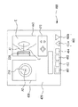
以下、本発明の実施の形態を図面に基づいて説明する。図1は、本実施形態である眼科用レーザ手術装置の概略構成図である。図2は、眼球固定ユニットの構成図である。本実施形態においては、術眼Eの軸方向(奥行方向)をZ方向、水平方向をX方向、鉛直方向をY方向として説明する。 Hereinafter, embodiments of the present invention will be described with reference to the drawings. FIG. 1 is a schematic configuration diagram of an ophthalmic laser surgical apparatus according to the present embodiment. FIG. 2 is a configuration diagram of the eyeball fixing unit. In this embodiment, the axial direction (depth direction) of the operative eye E will be described as the Z direction, the horizontal direction as the X direction, and the vertical direction as the Y direction.
<装置の全体構成>
装置の構成の概略を説明する。本装置は、術眼(患者眼)Eの眼球組織(水晶体LE)に手術用のレーザ光(レーザビーム)を照射し、水晶体の切断・破砕を行う眼科用レーザ手術装置である。
<Overall configuration of device>
An outline of the configuration of the apparatus will be described. This apparatus is an ophthalmic laser surgical apparatus that irradiates a surgical laser beam (laser beam) to an eyeball tissue (lens LE) of an operating eye (patient eye) E to cut and crush the crystalline lens.
眼科用レーザ治療装置500は、大別して、パルスレーザ光を術眼Eに照射するレーザ照射ユニット(本体部)100と、レーザ照射ユニット100に対して術眼Eの眼球を固定保持する眼球固定・インターフェイスユニット200、術眼Eの前眼部の正面像及び前眼部の断層像を撮影するための観察・撮影ユニット300、装置500を操作するための操作ユニット400、装置全体を統括制御する制御部70、を備えている。観察・撮影ユニット300は、術眼Eの断層像を撮影(取得)するための光干渉断層像撮影ユニット((OCT:Optical Coherence Tomography)ユニットと略す)310と、術眼Eの前眼部像を撮影する正面観察ユニット350と、を備えている。
The ophthalmic
<レーザ照射ユニット>
レーザ照射ユニット100は、手術用のパルスレーザ光(レーザビーム)を出射するレーザ光源ユニット110と、レーザ光を導光するための光学部材を含むレーザ照射光学系120と、術眼の絶対位置を検出する位置検出ユニット190と、を備えている。レーザ照射光学系120は、装置本体に内蔵されている。レーザ照射光学系(レーザデリバリ)120は、レーザスポットをZ方向に沿って移動させるためのビームエキスパンダユニット130、レーザスポットをXY方向に移動させる走査部140、レーザ光をレーザスポットとしてターゲット位置に集光させる集光光学系(結像光学系)としての対物レンズ150、レーザ光を導光するための各種光学部材、を備えている。
<Laser irradiation unit>
The
レーザ光源ユニット110は、集光点(集光されたレーザスポット)でプラズマを発生させる(ブレイクダウンを起こす)パルスレーザを出射するレーザ光源である。レーザスポットでは、プラズマが発生する。プラズマによってターゲット位置(スポット)でブレイクダウン(光破壊)が起こり、ターゲット位置の眼球組織が機械的に破壊される。レーザスポットが繋げられることによって、眼球組織である水晶体が切断、破砕される。レーザ光源ユニット110としては、1フェムト秒から10ナノ秒のパルス幅のパルスレーザ光を出射するデバイスが用いられる。本実施形態では、10ピコ秒のパルス幅を持ち、450nmを中心波長として±10nmの波長幅を持つ紫外域のパルスレーザを出射するレーザ光源を用いる。また、レーザ光源ユニット110には、レーザスポットのスポットサイズが1〜15μmでブレイクダウンを発生させる出力のレーザ光を出射可能なレーザ光源を用いる。なお、レーザ光源としては、パルス幅500フェムト秒で、波中心波長が、1040nm(波長幅は、±10nm)である赤外域のパルスレーザ光を出射するデバイスを用いてもよい。
The laser
ビームエキスパンダユニット130(以下、単にエキスパンダという)は、複数の光学素子を備え、エキスパンダ130を通過したパルスレーザ光のビームの発散状態を変更することによって、レーザスポットをZ方向(光軸L1上)に沿って移動させる。本実施形態のエキスパンダ130は、上流側(レーザ光源ユニット110側)から負の屈折力を持つレンズと、正の屈折力を持つレンズと、を配置し、上流側のレンズを光軸に沿って移動させる構成とする。これにより、エキスパンダ130を出射したビームの発散状態(発散角、収束角、等)が変えられる。対物レンズ150に入射するパルスレーザ光の発散状態によって、レーザスポットの集光位置がZ方向上で変わることとなる。
The beam expander unit 130 (hereinafter simply referred to as an expander) includes a plurality of optical elements, and changes the divergence state of the beam of the pulsed laser light that has passed through the
走査ユニット(光スキャナユニット)140は、X方向にレーザ光を移動させるためのガルバノミラーと、Y方向にレーザ光を移動させるためのガルバノミラーと、を備えている。なお、走査ユニット140としては、レーザ光をXY方向に走査できる構成であればよい。例えば、X方向の走査をポリゴンミラーとし、Y方向の走査をガルバノミラーとする構成としてもよい。また、レゾナントミラーをX方向とY方向に対応させて用いる構成としてもよい。また、2つのプリズムを独立して回転させる構成でもよい、
このようにして、エキスパンダ130と走査ユニット140によって、レーザスポットが、術眼Eの眼球組織内(ターゲット内)で3次元的(XYZ方向)に移動される。エキスパンダ130と走査ユニット140によって移動光学系が構成される。エキスパンダ130が走査ユニット140より上流に配置されることにより、レーザ光がXY方向に振られた後でエキスパンダ130を通過することがない。このため、エキスパンダ130の光学部材の有効径、サイズを小さくできる。ここでは、レンズ131を小さくできることで、レーザスポットのZ方向の移動を早くできる。
The scanning unit (optical scanner unit) 140 includes a galvanometer mirror for moving the laser beam in the X direction and a galvanometer mirror for moving the laser beam in the Y direction. The
In this manner, the
走査ユニット140と対物レンズ150の間には、レーザ光軸と観察・撮影光軸を同軸とするためのビームコンバイナ(ビームスプリッタ)301が配置される。コンバイナ301は、パルスレーザ光を反射し、観察・撮影ユニットの照明光を透過する特性を有している。対物レンズ150は、装置本体に対して固定的に配置されたレンズである。図2に示すように、対物レンズ150は、装置本体に固定されたレンズホルダ151に保持される。対物レンズ150は、レーザ光をスポットサイズが、1〜15μm程度の微小なレーザスポットとしてターゲットに結像させる。
A beam combiner (beam splitter) 301 is arranged between the
なお、図示は略すが、術者がレーザ照射位置を確認するための照準光(エイミング光)を出射するエイミング光源をレーザ照射ユニット100に設ける。
Although not shown, the
<位置検出ユニット>
位置検出ユニット190は、レーザ照射光学系120を共用する。位置検出ユニット190は、共焦点開口板、受光素子を備えている。共焦点開口板の開口は、レーザスポットの位置の共役とされる。これにより、受光素子は、レーザスポット位置の光(組織での反射光)を検出できる。エキスパンダ130、走査ユニット140の光学素子の位置情報から、レーザスポットの絶対位置での情報を取得できる。例えば、レーザスポット位置の反射光を受光素子で受光し、光強度を得ることによって、絶対位置が定まったレーザスポット(ターゲット)位置の情報が得られる。なお、絶対位置の検出において、レーザ光源ユニット110の出力は、減衰器等によって低下させ、レーザスポット位置でのブレイクダウンを発生させないようにする。なお、
位置検出ユニットは、術眼の特徴部分の絶対位置を検出する構成としたが、この構成に限るものではない。位置検出動作によって、レーザ照射光学系120の制御情報を得る構成としてもよい。
<Position detection unit>
The
The position detection unit is configured to detect the absolute position of the characteristic part of the surgical eye, but is not limited to this configuration. It is good also as a structure which obtains the control information of the laser irradiation
<眼球固定・インターフェイスユニットユニット>
眼球固定・インターフェイスユニット200は、術眼Eの眼球をレーザ照射光学系120(装置本体)に対して固定(保持)し、術眼Eの組織にレーザ光を導光する役割を持つ。眼球固定・インターフェイスユニット200は、レーザ照射光学系120の端部周辺(対物レンズ150周辺)に配置される。対物レンズ150は、装置本体に固定的に配置されたホルダ151に保持されている。眼球固定・インターフェイスユニット200は、大別して、術眼Eを吸着によって固定するためのサクションリング(吸着ユニット、眼球固定ユニット)210、サクションリング210を装置本体に対して保持する第1保持ユニット(サクションリング保持ユニット)250、術眼Eの角膜を覆ってレーザ光を眼球組織に導光するためのインターフェイスユニット220、インターフェイスユニット220を装置本体に対して保持する第2保持ユニット260、を備えている。
<Eyeball fixation / Interface unit unit>
The eyeball fixing /
サクションリング210は、術眼Eの強膜に接触する接触部となるリング211、リング211を支える支持部212、リング211に吸引圧を付加する流路(通気孔)である吸引用パイプ214、支持部212を貫通して形成された流路(貫通孔)であって液体を供給・排出するための液体供給排出用のパイプ215、を備えている。サクションリング210は、支持部212の基端に形成された基部213からリング211に向かってテーパとなる円錐形状となっている。サクションリング210は、吸引ポンプ(図示を略す)から付加される吸引圧をパイプ214を介してリング211に伝達(付加)する。
The
リング211は、強膜の曲面に沿う開口を有する。リング211の開口は眼球の輪部(角膜周辺部)を囲う形状であり、リング211にあわせたリング形状となっている。これにより、眼球がリング211に対して均一に吸着される。支持部212は、眼球をリング211に吸着させて状態で支持部212の内側に液体が満たすことができるように、リング211(眼球)を囲う壁状となっている。また、サクションリング210において、支持部212の内側にインターフェイスユニット220が接触(干渉)することなく収まるような空間が形成されている。支持部212の基部213は、支持部212が第1保持ユニット250と着脱可能となるような形状(嵌合形状)となっている(詳細は後述する)。パイプ214には、装置本体の設けられた(又は別ユニットの)吸引ポンプからの吸引チューブが接続される。吸引ポンプの操作により発生した吸引圧によって、吸引チューブ、パイプ214、リング211内が負圧となり、術眼Eの強膜がリング211の開口に吸着される。パイプ215の端部(開口)は、支持部212の内壁の形成される。パイプ215には、図示を略す灌流吸引ユニットにチューブ等を介して接続される。レーザ照射前には、灌流吸引ユニットの動作により、サクションリング210内に液体が供給される。手術後には、サクションリング210内の液体が排出される。なお、液体は、パイプ215を介して供給されるだけの構成であってもよい。術がにサクションリング210を術眼Eから取り外す作業により、液体を廃棄する構成としてもよい。
The ring 211 has an opening along the curved surface of the sclera. The opening of the ring 211 has a shape that surrounds the annular portion (corner peripheral portion) of the eyeball, and has a ring shape that matches the ring 211. Thereby, the eyeball is attracted uniformly to the ring 211. The
サクションリング210は、生体適合性を有する樹脂、金属、等の素材で形成されている。サクションリング210は、一回の使用で廃棄されるディスポーザブルタイプとなっている。このため、第1保持ユニット250に対して着脱可能な構成となることが好ましい。
The
第1保持ユニット250は、装置本体側に取り付けられている。第1保持ユニット250は、基部213と嵌合する保持部(嵌合部)251、保持部251の基端に形成された基部252の移動方向をZ方向にガイドするレール(シャフト)253、基部252の上下に配置される弾性部材254、保持部251の移動を規制する規制部255、保持部251のZ方向での位置を検出するセンサ256、を備えている。
The first holding unit 250 is attached to the apparatus main body side. The first holding unit 250 includes a holding portion (fitting portion) 251 fitted to the
保持部251は、対物レンズ150の径よりも大きい径のリング形状である。保持部251(の先端)は、支持部212を着脱可能に保持するために、支持部212の基部213と互いに嵌め合う構造を備えている。保持部251は、サクションリング210を保持すると共に位置決めする役割を持っている。例えば、保持部251には溝(リング状の溝)が形成され、基部213には突起(リング状の突起)が形成される構造とする。基部213が保持部251に押し付けられることによって溝に突起が嵌合し、サクションリング210が保持部251に保持される。
The holding
他の構成としては、保持部251と基部213に互いに螺合するネジ山が形成されており、サクションリング210の回転によって、保持部251に基部213が螺合する(嵌合する)構成としてもよい。また、磁力、吸引等によって、基部213を保持部部251を着脱可能に保持させる構成としてもよい。
As another configuration, the holding
保持部251の基部252は、保持部251のフランジを形成する。保持部251の基部252は、リング形状である。基部252にレール253が嵌る穴(符号を略す)がZ方向に沿って形成されている。レール253は、装置本体に固定的に配置され、基部252の移動方向をZ方向とするためにZ方向(上下方向と一致)に沿って配置される。弾性部材254は、基部252の上側と下側にそれぞれ配置されている。保持部251の基部252とレール253が、第1保持ユニット250、サクションリング210をZ方向に移動可能とする移動機構である。第1保持ユニット250は、サクションリング210を移動させる移動ユニット(アライメントユニット)として用いられる。弾性部材254は、レール253に沿ってZ方向に配置され、基部252をZ方向に付勢する。弾性部材254としては、付勢力(復元力)を持つものであればバネ、ゴム等が用いられる。基部252の上側に位置する弾性部材254は上端が固定され、下端が基部252に接している(固定されている)。基部252の下側に位置する弾性部材254は、上側を基部252に接しており(固定されており)、下端が固定されている。基部252の下側に位置する弾性部材254は、基部252を上方へと付勢する。基部252の上側に位置する弾性部材254は、基部252を下方へと付勢する。弾性部材254により基部252(保持部251等)は、均衡してレール253上に位置することとなる。
The
基部252が弾性部材254に付勢された状態で、基部252に過剰な力が加わると、基部252(保持部251)が力を受けて逃げることとなる。例えば、術眼Eがサクションリング210に吸着された状態で、サクションリング210が下方に移動するような場合、術眼Eはサクションリング210に押される。術眼Eが受ける圧力が、弾性部材254の付勢力を超えると、基部252は、上方への力を受ける。サクションリング210、保持部251、基部252は上方へ移動する(逃げる)。これにより、術眼Eは、一定以上の押圧を受けにくくなる(術眼Eへの力が緩衝される)。このようにして、第1保持ユニット250は、Z方向の力に対する緩衝機構を備えることとなる。このようにして、第1保持ユニット250(移動ユニット)は、緩衝機構を備えることとなる。
When an excessive force is applied to the base 252 in a state where the
規制部255は、基部252のZ方向での位置を固定する(ロックする)役割を持つ。ここでは、規制部255は、基部252を把持する機構を有し、指令信号に基づいて、Z方向における何れかの位置で基部252の位置を固定する構成となっている。規制部255は、制御ユニット70と接続されており、制御ユニット70からの信号に基づいて基部252の固定(規制)を行う。
The restricting
センサ256は、保持部251のZ方向の位置を検出する役割を持つ。例えば、センサ256は、保持部251の位置を検出するポテンショメータとする。センサ256は、制御ユニット70に接続されており、位置検出情報を制御ユニット70へと送る。制御ユニット70は、センサ256からの検出信号に基づいて規制部255に指令信号を送り、基部252の位置を固定する。規制部255が基部252を固定する条件としては、例えば、レーザ照射光学系120(対物レンズ150)に対して、術眼Eの位置が光学的にレーザ照射に適切な範囲(アライメント範囲)にある位置とする。サクションリング210、保持部251、基部252、のサイズは設計的に既知である。このため、センサ256の検出信号を受けた制御ユニット70は、対物レンズ150に対するリング211の位置を把握できる。
The
なお、センサ256は、フォトセンサであってもよい。例えば、基部252に遮光板を取り付ける構成とする。フォトセンサと遮光板により、フォトインタラプタを構成する。この場合、フォトセンサは、基部252が一定の範囲内にあるときに制御ユニット70に検出信号を送る構成とする。
The
インターフェイスユニット220は、術眼Eの角膜に近接し、角膜の屈折力の弱めて、レーザ光を水晶体等の眼球組織に到達(集光)し易くする役割を持つ。本実施形態のインターフェイスユニット220は、角膜に直接接触することなく、少なくとも角膜の一部を覆う構成とする。インターフェイスユニット220は、角膜を覆う光学部材であるカバーガラス(コンタクトガラス)221、カバーガラス211を支持する支持部222、を備える。インターフェイスユニット220は、支持部222の基端に形成された基部223を介して第2保持部260に設置されている。
The
カバーガラス(カバー)221は、角膜を覆う部材であり、少なくともレーザスポットが集光されるNAをカバーするサイズとなっている。カバーガラス221は、透光性を有する透明部材であり、例えば、ガラス、樹脂によって形成される。本実施形態では、カバーガラス221は、平面状(板状)となっている。カバーガラス221は、後述する液体の液面に位置し、液体を覆う役割を持つ。支持部222は、円錐状に形成されたテーパ状の部材であり、円錐の先端箇所でカバーガラス221を支持する。基部223には、第2保持ユニット260に着脱可能に保持されるように、互いに嵌め合う嵌合部が形成されている。
The cover glass (cover) 221 is a member that covers the cornea and has a size that covers at least the NA on which the laser spot is focused. The
インターフェイスユニット220は、サクションリング210の内側に収まる形状である。インターフェイスユニット220の各部材は、生体適合性を有する素材で形成される。インターフェイスユニット220は、サクションリング210と同様にディスポーザブルタイプとなっている。
The
第2保持ユニット(インターフェイスユニット保持ユニット)260は、第1保持ユニット250と同様に装置本体に設けられ、対物レンズ150の周辺に配置される。第2保持ユニット260は、第1保持ユニット250の内側に配置される。第2保持ユニット260は、支持部222の基部223と嵌合して支持部222を保持するための保持部(嵌合部)261、保持部261の基端に形成された基部262の移動方向をZ方向にガイドする送りネジ(シャフト)263、基部262を移動させるために送りネジ263を回転させる駆動部264、を備えている。
The second holding unit (interface unit holding unit) 260 is provided in the apparatus main body similarly to the first holding unit 250 and is arranged around the
保持部261は、対物レンズ150を囲うリング形状の部材である。保持部261は、支持部222を着脱可能に保持するために支持部222と互いに嵌め合う構成となっている。保持部261の基部262は、保持部261のフランジを形成する。保持部261の基部262は、基部252の径よりも小さい径のリング状部材である。
The holding
基部262には図示を略す雌メジが上下方向に沿って形勢されており、送りネジ263と螺合する。駆動部263は、例えば、パルスモータである。駆動部264の軸に送りネジ263が固定される。これにより、送りネジ263を軸回転される。送りネジ263の回転により、基部262がZ方向に沿って送られる。基部262、送りネジ263によって、移動機構が構成される。また、基部262、送りネジ263、駆動部264によりインターフェイスユニット220、第2保持ユニット260を移動可能とする移動ユニット(アライメントユニット)が構成される。駆動部264は、制御ユニット70に接続されており、制御ユニット70の指令信号に基づいて保持部261を移動させ、インターフェイスユニット220をZ方向に沿って移動させる。制御ユニット70は、操作ユニット400で入力された操作信号を指令信号として駆動部264に送り、インターフェイスユニット220を移動させる。本実施形態では、術者が、操作ユニット400を用いて、カバーガラス221の位置を定める構成となっている。
A female medium (not shown) is formed on the
インターフェイスユニット220は、サクションリング210に吸着された術眼Eの角膜に当接する。このとき、サクションリング210の内側には、液体(生理食塩水)LQが満たされている。カバーガラス221は、角膜に直接接触することなく、液体を介して角膜と当接する。カバーガラス221、液体LQにより、角膜の屈折力がキャンセルされ、レーザ光は、対物レンズ150からターゲットである水晶体まで屈折することなく導光される。
The
なお、インターフェイスユニット220は、角膜に直接接触する構成であってもよい。例えば、カバーガラスを角膜に接触させて、角膜を圧平し、レーザ光を照射する眼球組織(角膜実質)の位置決めを行う構成とする。角膜がカバーガラスと接触することによって、角膜の絶対位置がレーザ照射光学系に対して決まることとなる。この場合、カバーガラスは、角膜内等のレーザ照射領域をカバーするように角膜を覆う接触面を有していればよい。
The
このようにして、サクションリング210とインターフェイスユニット220は、独立してZ方向に移動可能とさせることができる。また、本実施形態では、サクションリング210、インターフェィスユニット220は、XY方向に動くことがない構成であるため、術眼Eの吸着等の作業がし易くなる。
In this way, the
装置500において、レーザ照射ユニット100、眼球固定・インターフェイスユニット200を術眼Eにアライメントさせるための(粗動の)アライメントユニット180を備える。移動ユニット180は、眼球固定・インターフェイスユニット200等の本体の一部を移動させる移動機構と、移動機構を駆動する駆動部(モータ、アクチュエータ等)を持ち、レーザ照射ユニット100(の光軸L1)、眼球固定・インターフェイスユニット200(の中心軸)を、術眼Eに対して3次元方向に移動させる。ここでは、光軸L1と、眼球固定・インターフェイスユニット200の中心軸、一致している。また、サクションリング210の中心軸と、インターフェイスユニット220の中心軸とは一致している。移動ユニット180は、制御ユニット70に接続されており、操作ユニット400からの操作信号に基いてレーザ照射ユニット100眼球固定・インターフェイスユニット200を移動させる。術者は、モニタ420に表示される術眼Eを確認しながら、XY方向の位置合せ(XYアライメント)を行い、Z方向の位置を合わせ(Zアライメント)を行う。ここでは、少なくともレーザ照射ユニット100と眼球固定・インターフェイスユニット200が一体的に移動する。移動ユニット180は、サクションリング210及びインターフェイスユニット220をZ方向に沿って移動させるアライメントユニットとなる。アライメントユニットは内部にエンコーダ等のセンサを備えている。このため、眼球固定・インターフェイスユニット200等の位置は制御ユニット70に取得される。なお、アライメント移動ユニットは、少なくともZ方向に移動する構成であればよい。例えば、レーザ照射ユニット100及び眼球固定・インターフェイスユニット200が手術顕微鏡等の別装置(レーザ照射ユニット100と連結されている)に取り付けられる構成で、XYアライメントを術者が持って移動させる構成であってもよい。
The
<観察・撮影ユニット>
観察・撮影ユニット300は、術眼Eの断層像を取得するOCTユニット310と、術眼Eの正面像を取得する正面像取得ユニット350と、を備えている。観察・撮影ユニット300は、ビームコンバイナ301によって、レーザ光軸L1と同軸とされる。観察・撮影ユニット300の光軸L2とされる。光軸L2はビームコンバイナ302により、OCTユニット310の光軸L3に分けられる。ビームコンバイナ302は、ダイクロイックミラーであり、OCTユニット310の測定光を反射し、正面観察ユニット350用の照明光(の反射光)を透過する特性を有している。
<Observation / shooting unit>
The observation /
<光断層像撮影ユニット>
光干渉断層像撮影ユニット(OCTユニット)310は、対物レンズ150を共用し、術眼E(の前眼部)の断層像を撮影するための干渉光学系(OCT光学系)320を備えている。
<Optical tomography unit>
The optical coherent tomography unit (OCT unit) 310 includes an interference optical system (OCT optical system) 320 that shares the
OCT光学系320は、術眼Eに測定光を照射する。OCT光学系320は、術眼Eから反射された測定光と,参照光との干渉状態を受光素子(検出器325)によって検出する。OCT光学系320は、術眼Eの撮像位置を変更するため、術底Eにおける測定光の照射位置を変更する照射位置変更ユニットである光スキャナ330を備える。光スキャナ330は、制御ユニット70に接続されており、制御ユニット70は、設定された撮像位置情報に基づいて光スキャナ330の動作を制御し、検出器325からの受光信号に基づいて断層像を取得する。
The OCT optical system 320 irradiates the surgical eye E with measurement light. The OCT optical system 320 detects the interference state between the measurement light reflected from the surgical eye E and the reference light by the light receiving element (detector 325). The OCT optical system 320 includes an optical scanner 330 that is an irradiation position changing unit that changes the irradiation position of the measurement light on the surgical base E in order to change the imaging position of the surgical eye E. The optical scanner 330 is connected to the
OCT光学系320は、いわゆる眼科用光断層干渉計の装置構成を持ち、本実施形態においては、少なくともパルスレーザ光が照射される前の術眼Eの断層像を撮像する。OCT光学系320は、測定光源321から出射された光(赤外光)をカップラー(光分割器)322によって測定光(試料光)と参照光に分割する。そして、OCT光学系320は、測定光学系によって測定光を術眼Eに導き、参照光を参照光学系323に導く。その後、術眼Eによって反射された測定光と,参照光との合成による干渉光を検出器(受光素子)により受光する。検出器は、測定光と参照光との干渉状態を検出する。フーリエドメインOCTの場合では、干渉光のスペクトル強度が検出器によって検出され、スペクトル強度データに対するフーリエ変換によって所定範囲における深さプロファイル(Aスキャン信号)が取得される。例えば、Spectral-Domain OCT(SD−OCT)、Swept-Source OCT(SS−OCT)が挙げられる。また、Time-Domain OCT(TD−OCT)であってもよい。 The OCT optical system 320 has an apparatus configuration of a so-called ophthalmic optical tomographic interferometer. In this embodiment, the OCT optical system 320 captures at least a tomographic image of the surgical eye E before irradiation with pulsed laser light. The OCT optical system 320 divides light (infrared light) emitted from the measurement light source 321 into measurement light (sample light) and reference light by a coupler (light splitter) 322. Then, the OCT optical system 320 guides the measurement light to the surgical eye E and guides the reference light to the reference optical system 323 by the measurement optical system. Thereafter, interference light obtained by combining the measurement light reflected by the surgical eye E and the reference light is received by a detector (light receiving element). The detector detects an interference state between the measurement light and the reference light. In the case of Fourier domain OCT, the spectral intensity of the interference light is detected by a detector, and a depth profile (A scan signal) in a predetermined range is acquired by Fourier transform on the spectral intensity data. Examples include Spectral-Domain OCT (SD-OCT) and Swept-Source OCT (SS-OCT). Moreover, Time-Domain OCT (TD-OCT) may be used.
光源から出射された光は、カップラーによって測定光束と参照光束に分割される。測定光束は、光ファイバを通過した後、空気中へ出射される。その光束は、測定光学系及び光スキャナを介して術眼Eに集光される。そして、術眼Eで反射された光は、同様の光路を経て光ファイバに戻される。参照光学系は、術眼Eでの測定光の反射によって取得される反射光と合成される参照光を生成する。 The light emitted from the light source is divided into a measurement light beam and a reference light beam by a coupler. The measurement light flux passes through the optical fiber and is then emitted into the air. The light beam is condensed on the surgical eye E via the measurement optical system and the optical scanner. Then, the light reflected by the surgical eye E is returned to the optical fiber through the same optical path. The reference optical system generates reference light that is combined with reflected light acquired by reflection of measurement light by the surgical eye E.
参照光学系は、参照光路中の光学部材を移動させることにより、測定光と参照光との光路長差を変更する構成を有する。例えば、参照ミラーが光軸方向に移動される。光路長差を変更するための構成は、測定光学系の測定光路中に配置されてもよい。 The reference optical system has a configuration that changes the optical path length difference between the measurement light and the reference light by moving an optical member in the reference light path. For example, the reference mirror is moved in the optical axis direction. The configuration for changing the optical path length difference may be arranged in the measurement optical path of the measurement optical system.
OCTユニット310は、測定光束を偏向するための光スキャナを備える。光スキャナは、回転軸が互いに直交した2つのガルバノミラーによって構成される。光スキャナは、制御ユニット70からの指令信号に基づいて、測定光束を2次元的に偏向する機能を有する。光スキャナは、術眼EでXY方向(横断方向)に測定光を走査させる。本実施形態では、術眼Eの前眼部で測定光を走査する構成とする。例えば、光スキャナ330を、直線状(例えば、Y方向)に動作させ、検出器で取得した深さ情報(奥行情報)を直線状に並べることによって断層像を得る(いわゆる、Bスキャン)。
The
このようにして、光源から出射された光束はその反射(進行)方向が変化され、前眼部で任意の方向に走査される。これにより、術眼Eの撮像位置が変更される。光スキャナとしては、光を偏向させる構成であればよい。例えば、反射ミラー(ガルバノミラー、ポリゴンミラー、レゾナントスキャナ)の他、光の進行方向を変化させる(偏向させる)音響光学素子(AOM)等が用いられる。なお、上記OCTユニットの詳しい構成については、例えば、特開2008−29467号公報を参考にされたい。 In this manner, the reflection (advance) direction of the light beam emitted from the light source is changed, and the light beam is scanned in an arbitrary direction by the anterior eye part. Thereby, the imaging position of the surgical eye E is changed. The optical scanner only needs to be configured to deflect light. For example, in addition to a reflection mirror (galvano mirror, polygon mirror, resonant scanner), an acousto-optic element (AOM) that changes (deflects) the traveling direction of light is used. For the detailed configuration of the OCT unit, refer to, for example, Japanese Patent Application Laid-Open No. 2008-29467.
<正面観察ユニット>
正面観察ユニット350は、術眼Eの前眼部の正面像を取得する機能を有する。本実施形態では、正面観察ユニット350は、可視光により照明された術眼Eの前眼部像を撮影し、後述するモニタに表示する。正面観察ユニット350は、観察光学系(正面像観察光学系)を備え、2次元の撮像素子を備えるカメラユニットと、観察像をリレーするためのリレーレンズを備える。正面像観察ユニット350は、対物レンズ150を共用している。また、術眼Eの前方周辺には、可視照明光を発光する照明光源390が配置されている。撮影された正面像は、制御ユニット70へと送られる。
<Front observation unit>
The
<操作ユニット>
操作ユニット400は、レーザ照射ユニット100から治療レーザ光を出射させるトリガ信号を入力するためのトリガスイッチ410、術眼Eの断層像、前眼部像を表示したり、手術条件を表示する表示手段であるモニタ420、を備える。モニタ420は、タッチパネル機能を有し、手術条件の設定、断層像上での手術部位の設定を行う入力手段を兼ねる。なお、ポインティングデバイスであるマウス、数値、文字等を入力するため入力デバイスであるキーボード、等を入力手段として用いることもできる。
<Operation unit>
The
モニタ420は、術眼Eの前眼部を表示する前眼部表示部430、術眼Eの前眼部の断層像を表示するOCT像表示部440、手術条件を表示する手術条件表示部450、眼球固定するための操作を行う眼球固定操作部(眼球固定・インタフェース操作部)460、レーザ照射ユニット100等の移動を操作する移動ユニット操作部470、を備えている。
The
OCT像表示部440では、術者により手術部位(レーザ照射の範囲)がグフィカルに指定される。モニタ420上で指定された手術部位は、OCT像上での領域を指定する信号として制御ユニット70へと送られる。手術条件表示部450では、術者の操作により、水晶体を破砕(切開)する治療レーザ光の照射パターンが設定される。照射パターンは予め複数用意されており、術者の選択によって設定される。手術条件表示部450で、照射パターンが設定されると、モニタ420は、設定信号を制御ユニット70へと送る。なお、本実施形態では、レーザ出力、レーザスポットのスポットサイズ、等は不変とし、術者が設定を変更しないものとしているが、術者により設定する構成としてもよい。
In the OCT
OCT像表示部440(モニタ420)は、術者がサクションリング210、インターフェイスユニット220の位置合わせを視覚的に行いやすいように、OCT像上にサクションリング210、インターフェイスユニット220をグラフィカルに表示する役割を持つ。
The OCT image display unit 440 (monitor 420) serves to graphically display the
本実施形態では、OCT像表示部440において、少なくともサクションリング210、インターフェイスユニット220の位置決めが完了するまでは、OCT像が動画表示される。OCT像では、術眼Eの角膜及び角膜周辺(輪部周辺の強膜、サクションリング210(リング211)が写り込んで撮影されている。ここでは、眼球固定時のOCT像では、少なくとも術眼Eの角膜と、リング211が含まれる。カバーガラス221の位置決め時のOCT像では、少なくとも、角膜とカバーガラス221が含まれる。
In the present embodiment, the OCT image is displayed as a moving image in the OCT
眼球固定操作部460には、サクションリング210(リング211)に付加される吸引圧を設定する吸引圧設定部461、サクションリング210により眼球を吸着する指令信号を入力する吸引スイッチ462、サクションリング210内に液体を供給する指令信号を入力する供給スイッチ463、サクションリング210内から液体を排出する指令信号を入力する排出スイッチ464、インターフェイスユニット220の位置(高さ位置)を調節するための上下動スイッチ465、が配置されている。
The eyeball fixing
吸引圧設定部461が操作されると、吸引圧の数値を設定するためのテンキーが表示される。数値を入力すると、設定値としてメモリ71(後述)に記憶される。制御ユニット70は、設定された吸引圧に基づいて吸引ポンプを制御する。吸引スイッチ462が操作されると、リング211に付加(印加)される吸引圧がオン・オフされる。スイッチ463が操作されると、指令信号が制御ユニット70へと送られる。信号を受けた制御ユニット70は、灌流吸引ユニットを制御し、パイプ215を介して液体をサクションリング210内に供給し、一定の水位とする。スイッチ464が操作されると、指令信号が制御ユニット70へと送られる。信号を受けた制御ユニット70は、吸引排出ユニットを制御し、パイプ215を介してサクションリング210内の液体を排出する。スイッチ465には、上方に向いたカーソル465aと、下方へ向いたカーソル465bと、を含む。カーソル465aが操作されると、インターフェイスユニット260をZ方向に沿って上方向に移動させるための指令信号(操作信号)が制御ユニット70へと送られる。信号を受けた制御ユニット70は、駆動部264を制御し、カバーガラス221を上方へと移動させる。逆に、カーソル465bが操作されると、制御ユニット70は、カバーガラス221を下方へと移動させる。詳細は後述するが、術者は、モニタ420に表示される術眼Eの動画像を見ながら眼球固定ユニットを移動させ、眼球固定を行う。このため、モニタ420は、眼球固定ユニットを位置決めするための手段(モニタリングユニット)となる。
When the suction
移動ユニット操作部470は、移動ユニット180に、XYZ方向に移動させる指令信号(操作信号)を入力するための入力手段となっている。操作部270は、X方向、Y方向、Z方向のそれぞれに対して正負の方向に配置されたカーソルを備えている。カーソルが操作されることで、方向に対応した指令信号が制御ユニット70へと送られる。
The moving
<制御系>
装置500全体を統括・制御(表示制御、駆動制御)する制御ユニット70は、CPU(Central Processing Unit)である。制御ユニット70には、レーザ光源ユニット110、エキスパンダ130、走査ユニット140、位置検出ユニット190、規制部255、センサ256、駆動部264、OCTユニット310、正面観察ユニット350、操作ユニット400(トリガスイッチ410、モニタ420)、移動ユニット180、吸引ポンプ、灌流吸引ユニット、が接続される。また、制御ユニット70には、手術条件、照射パターン(レーザスポットを移動させるパターン)、眼球固定・インターフェイスユニット200の制御プログラム、等を記憶するメモリ71が接続される。また、制御ユニット70には、作業終了、警告等を術者に報知するためのブザー72が接続される。眼球固定ユニット160、照明光源390は、個別に駆動される。
<Control system>
A
制御ユニット70は、眼球固定・インターフェイスユニット200で術眼Eの固定が完了した後に、位置検出ユニット190を用いて術眼Eの特徴部位(水晶体前嚢)の絶対位置を取得して、レーザ照射位置の補正を行う(アライメント)。
The
制御ユニット70は、手術用のレーザ光の照射よりも前に、OCT像表示部440で設定された手術部位(領域)と、位置検出ユニット190で取得した絶対情報とに基づき、手術用のレーザ光を照射するための位置情報を補正する。制御ユニット70は、補正された手術部位、手術条件、照射パターンに基づいてレーザ光源ユニット110からレーザ光を出射し、エキスパンダユニット130(駆動部135)、走査ユニット(ガルバノミラー141及び144)を制御して、レーザスポットを眼球組織で移動させ、眼球組織を切断、破砕する。
Based on the surgical site (region) set by the OCT
制御ユニット70は、眼球固定操作部470からの指令信号に基いてアライメントユニット180を駆動制御し、眼球固定・インターフェイスユニット200をレーザ照射ユニット100と共に、XYZ方向に移動させる。これにより、眼球固定・インターフェイスユニット200のXY方向の位置合せと、Z方向の粗銅の位置合せが行える。
The
制御ユニット70は、OCTユニット310等で取得した断層像を画像処理し、眼球固定・インターフェイスユニット200、術眼Eの組織の位置、形状を取得(検出、算出)、表示(表示制御)を行う役割を持つ。また、制御ユニット70は、断層像を表示する、又は、画像処理結果に基いて眼球固定・インターフェイスユニット200の駆動制御をすることによって眼球固定・インターフェイスユニット200の位置をモニタリングするモニタリングユニットの機能(の一部)を担う。
The
<手術の流れ>
次に、手術の流れを、眼球固定動作を中心に説明する。図3は、眼球固定・インターフェイスユニット200において、インターフェィスユニット220が最上部にある状態を示している。図4は、OCT像表示部440を示した図である。
<Surgery flow>
Next, the flow of the operation will be described focusing on the eyeball fixing operation. FIG. 3 shows a state in which the
術者は、保持部251にサクションリング210を、保持部261にインターフェイスユニット220を取り付ける。術者は、モニタ420の手術条件表示部450を操作し、手術条件を設定する。ここでは、水晶体を破砕するための照射パターンを選択する。照射パターンとしては、例えば、水晶体の前嚢だけを切開するパターン、前嚢切開及び水晶体核を分割するパターン(例えば、ニ分割、四分割、八分割、等)、前嚢切開及び水晶体核を小片に破砕するパターン、等から選択する。また、吸引設定部461で眼球固定時の吸引圧を設定する。照射パターンの設定信号、吸引圧の設定信号は、制御ユニット70へと送られ、メモリ71に記憶される。
The surgeon attaches the
次に、術者は、ベッド等に寝た患者(被術者)の術眼Eに、装置本体の光軸L1を位置決め(XYアライメント)する。装置本体をZ方向に移動させて、サクションリング210(リング211)を術眼Eの強膜に接近させる。このとき、術者は、前眼部表示部430と、OCT像表示部440に表示される動画像を見ながら作業する。術者は、サクションリング210の強膜に対する接触状態を動画像(正面像、OCT像)を見ながら確認する。制御ユニット70は、OCTユニット310で取得した動画像であるOCT像を画像処理し、術眼Eの角膜形状を抽出して角膜頂点の位置を抽出する。また、制御ユニット70は、術眼Eの虹彩を抽出して瞳孔中心位置を得る。そして、制御ユニット70は、角膜頂点と瞳孔中心を通る線を術眼Eの方向(眼球の軸を示す軸情報)とする。制御ユニット70は、OCT像上に軸を示すシンボル(マーク)A1を重畳表示する。また、制御ユニット70は、正面像取得ユニット350で取得した正面像を画像処理し、瞳孔中心位置をを抽出する。制御ユニット70は、瞳孔中心位置を示すシンボルA2を正面像に重畳表示する。シンボルA1、A2は、リアルタイムに更新表示される。これにより、術者は、モニタ420を見ながら、術眼Eの方向を確認でき、サクションリング210の中心に術眼Eの中心軸を位置合せしやすい。なお、シンボルA2は、角膜頂点位置を示すものであってもよい。また、シンボルA2は、シンボルA1(角膜頂点位置)を示す構成であってもよい。この場合、Bスキャンの方向が異なる複数のOCT像においてそれぞれ角膜頂点位置を抽出することが好ましい。
Next, the surgeon positions (XY alignment) the optical axis L1 of the apparatus main body on the surgical eye E of a patient (subject) who lies on a bed or the like. The main body of the apparatus is moved in the Z direction to bring the suction ring 210 (ring 211) closer to the sclera of the surgical eye E. At this time, the surgeon works while viewing the moving images displayed on the anterior
サクションリング210が術眼Eの強膜に接触した後も、術者は装置本体をZ方向に下げる。このとき、第1保持ユニット250の緩衝機構により、サクションリング210は術眼Eに過剰な圧力を掛けにくい。制御ユニット70は、センサ256の検出信号をモニタし、サクションリング210がアライメント範囲内に位置したか否かを判定する。サクションリング210がアライメント範囲内に位置したと判定されると、制御ユニット70は、規制部255に指令信号を送る。規制部255は、指令信号に基いてサクションリング210の移動をロックする。制御ユニット70は、ブザー72を制御し、サクションリング210の移動がロックされたことを術者に報知する。術者は、スイッチ462を操作して術眼Eをサクションリング210に吸着させる。術者がスイッチ463を操作すると、液体がサクションリング210内に満たされる。なお、制御ユニット70が、サクションリング210の移動のロックと共に、吸引を開始する構成としてもよい。また、制御ユニット70が、サクションリング210での吸着完了に基いて、液体を供給する構成としてもよい。
Even after the
次に、術者は、インターフェイスユニット220を角膜に対して位置決めさせる。術者は、OCT像を見ながら、カバーガラス221の位置(Z方向での高さ位置)と、角膜の位置を確認しながら、カーソル265b(或いは、カーソル265a)を操作して、角膜(頂点)に対してカバーガラス221前面(下面)が、一定の位置関係となるようにする。位置関係としては、角膜頂点とカバーガラス221前面が、1mm程度の距離とする。これは、液体の表面の揺れの影響を受けず、カバーガラス221が直接角膜に接触して患者に負担を掛けてしまわない距離である。
Next, the surgeon positions the
制御ユニット70は、操作ユニット400で入力された操作信号を指令信号として駆動部264に送る。制御ユニット70は、駆動部264を駆動させ、インターフェイスユニット220を被検眼に対してZ方向に移動させる。制御ユニット70は、操作ユニット400からの操作信号がオフとなったとき、駆動部264の駆動を停止させ、インターフェイスユニット220停止させる。なお、制御ユニット70が、OCT像の画像処理により、カバーガラス221前面の位置と、角膜頂点の位置とを検出してカバーガラス221の位置決めを行う構成としてもよい。
The
このようにして、術眼Eの眼球が固定され、カバーガラス211が位置決めされる。術者が、OCT像等の動画像を見ながら、サクションリング、インターフェイスユニットのZ方向の移動を行うことで、簡単に位置決め作業が行える。また、術眼の動画像を確認することで、術眼によって異なる強膜、角膜の位置に対応で、術眼に応じて好適な眼球固定ができる。 In this way, the eyeball of the surgical eye E is fixed and the cover glass 211 is positioned. The operator can easily perform the positioning operation by moving the suction ring and the interface unit in the Z direction while viewing a moving image such as an OCT image. Further, by confirming the moving image of the surgical eye, it is possible to fix the eyeball suitable for the surgical eye, corresponding to the position of the sclera and cornea that varies depending on the surgical eye.
また、本実施形態の装置は、装置本体に設けられたサクションリングとインターフェイスユニットを独立してそれぞれZ方向に移動可能な構成を持ち、サクションリングによって固定された術眼に対してインターフェイスユニットを移動させる。これにより、サクションリングによって固定された術眼とインタフェースユニットの位置関係を好適に調整できるため、術眼によって異なる強膜、角膜の位置に対応で、術眼に応じて好適な眼球固定ができる。さらに、インターフェイスユニットは、Z方向のガイド機構によってXY方向への移動が規制された状態にて、サクションリングに対してZ方向に移動可能であるため、インターフェイスユニットとサクションリングとのXY方向のずれの発生を回避できる。 In addition, the apparatus of this embodiment has a configuration in which the suction ring and the interface unit provided in the apparatus main body can be independently moved in the Z direction, and the interface unit is moved with respect to the surgical eye fixed by the suction ring. Let Thereby, since the positional relationship between the surgical eye fixed by the suction ring and the interface unit can be suitably adjusted, the eyeball can be suitably fixed according to the surgical eye, corresponding to the positions of the sclera and cornea that differ depending on the surgical eye. Further, since the interface unit is movable in the Z direction with respect to the suction ring in a state where movement in the XY direction is restricted by the guide mechanism in the Z direction, the interface unit and the suction ring are displaced in the XY direction. Can be avoided.
また、本実施形態の装置は、装置本体に設けられたサクションリングとインターフェイスユニットを独立してそれぞれZ方向に移動可能な構成を持ち、術眼に対するサクションリングの固定、サクションリングによって固定された術眼とインタフェースユニットの位置関係の調整を、スムーズに行うことができ、効率的な手術が行える。 In addition, the apparatus of the present embodiment has a configuration in which the suction ring and the interface unit provided in the apparatus body can be independently moved in the Z direction, and the suction ring is fixed to the surgical eye, and the operation is fixed by the suction ring. The positional relationship between the eye and the interface unit can be adjusted smoothly, enabling efficient surgery.
眼球固定が完了すると、術者は、手術部位の設定を行う。術者は、OCT像表示部440のスイッチを操作し、プランニングを行う。プランニングが完了すると、制御ユニット70は、位置検出ユニット190を制御して、術眼Eの眼球組織の特徴部位の絶対位置を取得し、レーザ照射位置情報の補正を行う。補正結果はメモリ71に記憶される。
When the eyeball fixation is completed, the operator sets the surgical site. The surgeon operates the switch of the OCT
術者が、トリガスイッチ410を操作すると、制御ユニット70はトリガ信号に基いて設定された手術条件、照射パターン、補正されたレーザ照射位置情報、に基づいてレーザ照射を行う(レーザ照射光学系120の制御)。
When the operator operates the
レーザ照射によって、術眼の水晶体が切断、破砕され、水晶体前嚢が切開される。制御ユニット70は、レーザ照射が完了すると、ブザー72によって術者に報知する。術者は、スイッチ465aを操作して、インターフェイスユニット220を上方へと移動させる。また、術者は、スイッチ464を操作して、サクションリング210内の液体を排出させる。そして、術者は、スイッチ462を操作してサクションリング210による吸着を解除し、サクションリング210を術眼Eから取り外す。なお、レーザ照射完了後の処理を、制御ユニット70が行う構成としてもよい。
The lens of the surgical eye is cut and broken by laser irradiation, and the anterior lens capsule is incised. When the laser irradiation is completed, the
眼球固定・インターフェイスユニット200が取り外された術眼は、別の手術装置、例えば、超音波白内障手術装置によって、手術される。
The surgical eye from which the eyeball fixing /
なお、以上の説明では、サクションリング、インターフェイスユニットは、ディスポーザブルタイプ(ワンユースタイプ)としたが、これに限るものではない。眼球の固定ができればよく、リユースタイプであってもよい。この場合、繰り返し滅菌が可能な素材、ステンレス鋼、ガラス、等を用いて、それぞれのユニットを形成する。 In the above description, the suction ring and the interface unit are disposable types (one-use type), but are not limited thereto. It may be a reusable type as long as the eyeball can be fixed. In this case, each unit is formed using a material that can be repeatedly sterilized, stainless steel, glass, or the like.
なお、以上説明した本実施形態では、サクションリングによる術眼の吸着の後に、インターフェイスユニットを術眼に当接させる構成としたが、これに限るものではない。眼球固定が行えればよく、作業の順番が逆であってもよい。 In the embodiment described above, the interface unit is brought into contact with the surgical eye after the suction of the surgical eye by the suction ring. However, the present invention is not limited to this. It is sufficient if the eyeball can be fixed, and the order of operations may be reversed.
なお、以上の説明では、サクションリング、インターフェイスユニットは、Z方向に移動する構成となっていたが、これに限るものではない。2つのユニットが、独立して移動する構成であればよく、それぞれのユニットが、XY方向(或いは回転)する構成であってもよい。 In the above description, the suction ring and the interface unit are configured to move in the Z direction. However, the present invention is not limited to this. The two units may be configured to move independently, and each unit may be configured to rotate (or rotate) in the XY directions.
なお、以上の説明では、サクションリングが移動する構成となっていたが、これに限るものではない。サクションリングとインターフェイスユニットが相対的に移動する構成であればよい。例えば、サクションリングをZ方向に移動させる機構は必ずしも必要ない。 In the above description, the suction ring moves. However, the present invention is not limited to this. It is sufficient if the suction ring and the interface unit move relatively. For example, a mechanism for moving the suction ring in the Z direction is not necessarily required.
なお、以上の説明では、OCT像には撮影した画像(動画像)を用いて眼球固定ユニットの位置決めを行う構成としたが、これに限るものではない。例えば、少なくともサクションリングのリングの位置を示すシンボル(イラスト、フレーム等)をOCT像に重畳表示する構成としてもよい。例えば、サクションリングの部材の構成、第1保持ユニットのセンサの検出信号から、サクションリングのリングの位置を求め、OCT像に表示させる構成としてもよい。これによって、画像に写りこみにくい部材の位置をモニタ上で確認できる。 In the above description, the OCT image is configured to position the eyeball fixing unit using a captured image (moving image). However, the present invention is not limited to this. For example, at least a symbol (illustration, frame, etc.) indicating the position of the ring of the suction ring may be displayed superimposed on the OCT image. For example, the position of the ring of the suction ring may be obtained from the structure of the member of the suction ring and the detection signal of the sensor of the first holding unit and displayed on the OCT image. As a result, the position of the member that is difficult to appear in the image can be confirmed on the monitor.
また、制御ユニット等の画像処理によってOCT像から術眼の形状を抽出して、眼球固定等に利用する構成としてもよい。例えば、眼球固定動作の前に取得したOCT像(別の撮影装置で取得したOCT像でもよい)を画像処理し、角膜形状と、サクションリングが接触する角膜周辺の形状(眼球形状)を抽出しておく。眼球形状は、角膜頂点付近を通る直交するライン(Bスキャン)によって取得された3次元形状であることがこのましい。眼球固定動作の際に、術眼の角膜形状を取得して、予め取得していた角膜形状とマッチングさせることによって、術眼の角膜周辺の形状と位置を取得する。得られた角膜周辺の形状と位置をOCT像上にシンボル表示する構成とする。これにより、OCTユニットで角膜周辺を撮影できなくても、術者が角膜周辺の位置を確認(予測)しながらサクションリングの位置決めが行える。 Further, the configuration may be such that the shape of the surgical eye is extracted from the OCT image by image processing such as a control unit and used for eyeball fixation or the like. For example, an OCT image acquired before the eyeball fixing operation (an OCT image acquired by another imaging apparatus) may be image-processed to extract a corneal shape and a shape around the cornea (eyeball shape) in contact with the suction ring. Keep it. The eyeball shape is preferably a three-dimensional shape acquired by orthogonal lines (B scan) passing through the vicinity of the apex of the cornea. During the eyeball fixing operation, the corneal shape of the surgical eye is acquired and matched with the previously acquired corneal shape, thereby acquiring the shape and position around the cornea of the surgical eye. The shape and position around the obtained cornea are displayed as symbols on the OCT image. Thereby, even if the OCT unit cannot capture the periphery of the cornea, the operator can position the suction ring while confirming (predicting) the position around the cornea.
なお、以上の説明では、OCTユニットが、眼球固定ユニット、インターフェイスユニットの少なくとも一部が含むOCT像を取得する構成としたが、これに限るものではない。OCT像上で眼球固定ユニット等の位置、形状がわかる構成であればよい。例えば、眼球固定ユニット等の一部を示すイラスト等をOCT像上にシンボルとして表示する構成としてもよい。具体的には、制御ユニットが、サクションリングの位置をセンサ、アライメントユニットの情報(位置の検出結果)により取得し、OCT像上にサクションリングを模した形状のイラストを表示する。イラストは、サクションリングの設計情報から形状を模す。制御ユニットは、センサの位置情報に基づき表示を更新する。OCT像上のイラストによって、術者は、サクションリングの位置を知ることができ、位置合せがし易くなる。インターフェイスユニットの場合も同様に、駆動部、アライメントユニットの情報を取得し、インターフェイスユニットのイラスト(少なくとも)カバーガラスを示すをOCT像上に表示する。なお、眼球固定ユニット、インターフェイスユニットの一部がOCT像に含まれていてもシンボル表示してもよい。 In the above description, the OCT unit acquires an OCT image included in at least a part of the eyeball fixing unit and the interface unit. However, the present invention is not limited to this. Any configuration in which the position and shape of the eyeball fixing unit and the like are known on the OCT image may be used. For example, an illustration showing a part of the eyeball fixing unit or the like may be displayed as a symbol on the OCT image. Specifically, the control unit acquires the position of the suction ring from the information of the sensor and alignment unit (position detection result), and displays an illustration of the shape imitating the suction ring on the OCT image. The illustration mimics the shape from the design information of the suction ring. The control unit updates the display based on the sensor position information. By the illustration on the OCT image, the operator can know the position of the suction ring and can easily perform the alignment. Similarly, in the case of the interface unit, information on the drive unit and the alignment unit is acquired, and an illustration (at least) of a cover glass of the interface unit is displayed on the OCT image. A part of the eyeball fixing unit and the interface unit may be displayed as a symbol even if they are included in the OCT image.
なお、以上の説明では、サクションリング、インターフェイスユニットの位置合せを、術者の操作により行う構成としたが、これに限るものではない。各ユニットの位置合せができる構成であればよい。例えば、制御ユニットが、OCT像等に基いて術眼の位置を特定し、眼球固定ユニット等の位置を調整する構成としてもよい。具体的には、制御ユニットが、サクションリングユニットの設計情報とサクションリング内のセンサの検出結果に基いてサクションリングの位置を取得する。また、OCT像からサクションリングが接触する輪部の位置を取得する(又は)、角膜形状から予測する)。また、制御ユニットは、術眼の軸を得ておき、これらの情報を用いて、サクションリングのXYZ方向のアライメント、吸着動作を行う構成とする。インターフェイスユニットの場合も同様に、術眼の角膜(頂点)位置及びカバーガラスの形状と位置と、予め設定された角膜とカバーガラスの位置関係(カバーガラスの高さ)とに基いてインターフェイスユニットのZ方向のアライメントを行う構成とする。 In the above description, the suction ring and the interface unit are aligned by the operator's operation. However, the present invention is not limited to this. Any configuration may be used as long as each unit can be aligned. For example, the control unit may be configured to identify the position of the surgical eye based on the OCT image or the like and adjust the position of the eyeball fixing unit or the like. Specifically, the control unit acquires the position of the suction ring based on the design information of the suction ring unit and the detection result of the sensor in the suction ring. In addition, the position of the ring portion with which the suction ring contacts is acquired from the OCT image (or predicted from the corneal shape). In addition, the control unit obtains the axis of the operative eye and uses this information to perform the alignment and suction operation of the suction ring in the XYZ directions. Similarly, in the case of the interface unit, the position of the interface unit is determined based on the cornea (vertex) position of the operative eye and the shape and position of the cover glass, and the positional relationship between the cornea and the cover glass (the height of the cover glass). It is set as the structure which performs alignment of a Z direction.
また、眼球固定・インターフェイスユニット(レーザ照射ユニット)のXYの位置を、制御ユニットが位置合せする構成としてもよい。制御ユニットは、OCT像から取得した角膜頂点位置又は瞳孔中心位置と、眼球固定・インターフェイスユニットの中心軸(光軸L1)とのXY方向の差を算出する。制御ユニットは、算出結果の差がなくなるようにアライメントユニットを制御して眼球固定・インターフェイスユニットを移動させる。このとき、術眼の軸が中心軸に一致するようにアライメントユニットを制御する。 Further, the control unit may be configured to align the XY positions of the eyeball fixing / interface unit (laser irradiation unit). The control unit calculates the difference in the XY direction between the corneal apex position or the pupil center position acquired from the OCT image and the central axis (optical axis L1) of the eyeball fixing / interface unit. The control unit moves the eyeball fixation / interface unit by controlling the alignment unit so that there is no difference in the calculation results. At this time, the alignment unit is controlled so that the axis of the surgical eye coincides with the central axis.
なお、以上の説明では、OCT像の動画像をモニタに表示させる構成としたが、これに限るものではない。制御ユニットが、眼球ユニット等の位置合せを行う場合のモニタリングができる構成であればよい。撮影されたOCT像は内部で処理される構成としてもよい。この場合、制御ユニットがモニタリングユニットとして機能することとなる。 In the above description, the moving image of the OCT image is displayed on the monitor. However, the present invention is not limited to this. Any configuration may be used as long as the control unit can perform monitoring when aligning the eyeball unit or the like. The captured OCT image may be processed internally. In this case, the control unit functions as a monitoring unit.
なお、以上の説明では、断層像撮影ユニットとして、OCTユニットを用いる構成としたが、これに限るものではない。術眼の奥行情報、断層像を撮影できればよい。例えば、シャインプルーフカメラユニットを用いる構成としてもよい。 In the above description, the OCT unit is used as the tomography unit, but the present invention is not limited to this. It is only necessary to be able to capture depth information and tomographic images of the operative eye. For example, a configuration using a Shine proof camera unit may be used.
なお、以上の説明では、OCT像等をレーザ照射前(手術前)の眼球固定ユニットの位置合せに用いる構成としたが、これに限るものではない。レーザ照射中(手術中)に、OCT像を用いて眼球固定の状態をモニタ(確認)する構成としてもよい。例えば、制御ユニットが、画像処理により、OCT像から術眼の移動を検出する構成とする。制御ユニットが、OCT像から角膜形状、角膜頂点位置、等の術眼の特徴部分の情報を得ておく。制御ユニットが、特徴部分の位置をモニタして、特徴部分の移動を検出する。例えば、サクションブレイク等によって眼球が移動してしまった場合、制御ユニットは、検出結果に基づいてレーザ照射を停止し、術者に報知する構成とする。このような場合、サクションリングの吸引圧をモニタするセンサを用いた吸着状態の検出と比べて、吸着状態の検出を早くできる。また、吸着状態に限らず、OCT像等から術眼の変化を検出し、レーザ照射を停止する、レーザ照射(の位置)を補正する制御を行う構成としてもよい。 In the above description, the OCT image or the like is used for alignment of the eyeball fixing unit before laser irradiation (before surgery), but is not limited to this. It is good also as a structure which monitors (confirms) the state of eyeball fixation using an OCT image during laser irradiation (in operation). For example, the control unit is configured to detect movement of the surgical eye from the OCT image by image processing. The control unit obtains information on the characteristic features of the operative eye such as the corneal shape and the corneal apex position from the OCT image. The control unit monitors the position of the feature portion and detects the movement of the feature portion. For example, when the eyeball has moved due to a suction break or the like, the control unit is configured to stop laser irradiation based on the detection result and notify the operator. In such a case, the detection of the suction state can be performed faster than the detection of the suction state using a sensor that monitors the suction pressure of the suction ring. Further, not only the suction state but also a configuration in which a change in the operating eye is detected from an OCT image or the like, the laser irradiation is stopped, and the control for correcting the laser irradiation (position) is performed.
なお、以上の説明では、眼球固定ユニットの少なくとも一部、インターフェイスユニットの少なくとも一部、がOCT像に写り込む構成としたが、これに限るものではない。インターフェイスユニットの位置合せができる構成であればよく、インターフェイスユニットの一部がOCT像に写り込めばよい。これによって、画像表示、画像処理での角膜とインターフェイスユニットに位置関係が取得しやすい。 In the above description, at least a part of the eyeball fixing unit and at least a part of the interface unit are reflected in the OCT image. However, the present invention is not limited to this. Any configuration that allows alignment of the interface unit may be used, and a part of the interface unit may be reflected in the OCT image. Thereby, the positional relationship between the cornea and the interface unit in image display and image processing can be easily obtained.
なお、以上の説明では、眼球固定ユニットの一部、インターフェイスユニットの一部がOCT像に写り込む構成としたが、これに限るものではない。角膜に対して眼球固定ユニット、インターフェイスユニットの位置合せができる構成であればよい。各ユニットは必ずしもOCT像に写り込まなくてもよい。OCTユニットと角膜(表面)の位置関係は、撮影されたOCT像から取得できる。このため、OCTユニットと眼球固定ユニット、インターフェイスユニットの位置関係を定めることによって、眼球固定ユニット等が写り込まないOCT像を利用して角膜(術眼)と眼球固定ユニットの位置関係を取得して、各ユニットの位置合せを行うことができる。 In the above description, a part of the eyeball fixing unit and a part of the interface unit are reflected in the OCT image. However, the present invention is not limited to this. Any configuration capable of aligning the eyeball fixing unit and the interface unit with respect to the cornea may be used. Each unit does not necessarily have to be reflected in the OCT image. The positional relationship between the OCT unit and the cornea (surface) can be acquired from the captured OCT image. For this reason, by determining the positional relationship between the OCT unit, the eyeball fixing unit, and the interface unit, the positional relationship between the cornea (operating eye) and the eyeball fixing unit is obtained using an OCT image that does not include the eyeball fixing unit. , Each unit can be aligned.
なお、以上の説明では、OCT像を利用した眼球固定ユニット、インターフェイスユニットの位置合せにおいて、各ユニットが装置本体に固定的に配置された構成であったが、これに限るものではない。レーザ照射ユニットに対して眼球を固定する構成であればよい。例えば、眼球固定ユニットは装置とは独立したユニットであってもよい。この場合、眼球固定作業において、OCT像等を用いることによって、独立した眼球固定ユニットの位置決めがし易くなる。 In the above description, in the alignment of the eyeball fixing unit and the interface unit using the OCT image, each unit is fixedly arranged on the apparatus main body. However, the present invention is not limited to this. What is necessary is just the structure which fixes an eyeball with respect to a laser irradiation unit. For example, the eyeball fixing unit may be a unit independent of the device. In this case, it becomes easy to position the independent eyeball fixing unit by using an OCT image or the like in the eyeball fixing work.
なお、以上の説明では、眼球固定ユニット(サクションリング)は、眼球を吸引して、吸着固定する構成としたが、これに限るものではない。眼球を固定できる構成であればよい。例えば、眼球に接触し、眼球の動きを抑制する眼球固定ユニットであってもよい。 In the above description, the eyeball fixing unit (suction ring) is configured to suck and fix the eyeball by suction, but is not limited thereto. Any configuration that can fix the eyeball may be used. For example, an eyeball fixing unit that contacts the eyeball and suppresses the movement of the eyeball may be used.
なお、以上の説明では、パルスレーザ光を備える眼科用レーザ手術装置を例に挙げたが、これに限るものではなない。術眼(患者眼)の眼球を固定し、固定さた術眼の眼球組織にレーザ光を照射して手術、治療を行う構成であればよい。例えば、選択的線維柱帯形成術(Selective Laser Trabeculoplasity)を行うための眼科用レーザ手術装置であってもよい。この場合、レーザ光は、可視光のパルスレーザ等であり、レーザスポットのサイズは、数百μmとされ、術眼隅角の線維柱帯に照射される。 In the above description, an ophthalmic laser surgical apparatus provided with pulsed laser light is taken as an example, but the present invention is not limited to this. Any structure may be used as long as the eyeball of the surgical eye (patient eye) is fixed and the eyeball tissue of the fixed surgical eye is irradiated with laser light to perform surgery and treatment. For example, it may be an ophthalmic laser surgical apparatus for performing selective trabeculoplasty. In this case, the laser light is a visible light pulse laser or the like, the size of the laser spot is set to several hundred μm, and the trabecular meshwork at the corner of the surgical eye is irradiated.
以上のように本発明は実施形態に限られず、種々の変容が可能であり、本発明はこのような変容も技術思想を同一にする範囲において含むものである。 As described above, the present invention is not limited to the embodiment, and various modifications are possible. The present invention includes such modifications within the scope of making the technical idea the same.
100 レーザ照射ユニット
200 眼球固定・インターフェイスユニット
210 サクションリング
211 リング
220 インターフェイスユニット
221 カバーガラス
250 第1保持ユニット
260 第2保持ユニット
310 OCTユニット
400 操作ユニット
420 モニタ
440 OCT像表示部
500 眼科用レーザ手術装置
DESCRIPTION OF
Claims (5)
前記装置本体に取り付けられた眼球固定ユニットと、
前記眼球固定ユニットを術眼に対して移動させる移動ユニットと、
術眼の断層像を取得する断層像取得ユニットと、
前記眼球固定ユニットの位置を検出するためのセンサと、
前記断層像取得ユニットによって取得された断層像に基づいて術眼の位置を特定し、特定した前記術眼の位置と、前記センサによって検出された前記眼球固定ユニットの位置とに基づいて前記移動ユニットを制御することで、術眼に対して前記眼球固定ユニットをアライメントする制御ユニットと、
を備える、ことを特徴とする眼科用レーザ手術装置。 An irradiation optical system for irradiating a target laser beam for surgery to a target position, the apparatus main body having a laser irradiation optical system having a moving optical system for moving a laser beam spot three-dimensionally, and provided in the apparatus main body In an ophthalmic laser surgery apparatus that operates a surgical eye with a laser beam through a laser irradiation port,
An eyeball fixing unit attached to the apparatus body;
A moving unit for moving the eyeball fixing unit relative to the surgical eye;
A tomographic image acquisition unit for acquiring a tomographic image of the operative eye;
A sensor for detecting the position of the eyeball fixing unit;
The position of the surgical eye is specified based on the tomographic image acquired by the tomographic image acquisition unit, and the moving unit is determined based on the specified position of the surgical eye and the position of the eyeball fixing unit detected by the sensor. A control unit for aligning the eyeball fixing unit with respect to the surgical eye by controlling
An ophthalmic laser surgical apparatus comprising:
前記制御ユニットは、前記断層像取得ユニットによって取得された断層像から術眼の角膜頂点位置又は瞳孔中心位置を前記術眼の軸として特定し、前記眼球固定ユニットの中心軸と前記術眼の軸とが一致するように前記眼球固定ユニットをXY方向にアライメントすることを特徴とする眼科用レーザ手術装置。 The ophthalmic laser surgical apparatus according to claim 1,
The control unit specifies a corneal apex position or a pupil center position of a surgical eye from the tomographic image acquired by the tomographic image acquisition unit as an axis of the surgical eye, and a central axis of the eyeball fixing unit and an axis of the surgical eye The ophthalmic laser surgical apparatus is characterized in that the eyeball fixing unit is aligned in the X and Y directions so as to match .
前記眼球固定ユニットの内側に配置され、術眼と角膜の少なくとも一部を覆う透光性の光学部材を持つインターフェースユニットを備え、An interface unit that is disposed inside the eyeball fixing unit and has a translucent optical member that covers at least a part of the surgical eye and the cornea,
前記移動ユニットは、前記インターフェースユニットを術眼に対して移動可能であり、The moving unit is capable of moving the interface unit with respect to the operative eye,
前記制御ユニットは、前記断層像の画像処理によって検出された前記光学部材の前面位置と術眼の角膜頂点の位置とに基づいて前記移動ユニットを制御することで、術眼に対して前記インターフェースユニットをアライメントすることを特徴とする眼科用レーザ手術装置。The control unit controls the moving unit based on the front position of the optical member and the position of the corneal apex of the surgical eye detected by the image processing of the tomographic image, so that the interface unit with respect to the surgical eye An ophthalmic laser surgical apparatus characterized by aligning
前記制御ユニットは、前記断層像取得ユニットによって取得された断層像に基づいてレーザ照射中の術眼の移動を検出し、検出結果に基づいて術眼へのレーザ照射を停止することを特徴とする眼科用レーザ手術装置。The control unit detects movement of the surgical eye during laser irradiation based on the tomographic image acquired by the tomographic image acquisition unit, and stops laser irradiation to the surgical eye based on the detection result. Laser surgery device for ophthalmology.
前記制御ユニットは、前記センサによって検出された前記眼球固定ユニットの位置に基づいて、前記眼球固定ユニットの位置を示すシンボルをモニタ上に表示することを特徴とする眼科用レーザ手術装置。The control unit displays a symbol indicating a position of the eyeball fixing unit on a monitor based on the position of the eyeball fixing unit detected by the sensor.
Priority Applications (1)
| Application Number | Priority Date | Filing Date | Title |
|---|---|---|---|
| JP2012126625A JP6024218B2 (en) | 2012-06-02 | 2012-06-02 | Ophthalmic laser surgery device |
Applications Claiming Priority (1)
| Application Number | Priority Date | Filing Date | Title |
|---|---|---|---|
| JP2012126625A JP6024218B2 (en) | 2012-06-02 | 2012-06-02 | Ophthalmic laser surgery device |
Publications (3)
| Publication Number | Publication Date |
|---|---|
| JP2013248303A JP2013248303A (en) | 2013-12-12 |
| JP2013248303A5 JP2013248303A5 (en) | 2015-07-23 |
| JP6024218B2 true JP6024218B2 (en) | 2016-11-09 |
Family
ID=49847580
Family Applications (1)
| Application Number | Title | Priority Date | Filing Date |
|---|---|---|---|
| JP2012126625A Expired - Fee Related JP6024218B2 (en) | 2012-06-02 | 2012-06-02 | Ophthalmic laser surgery device |
Country Status (1)
| Country | Link |
|---|---|
| JP (1) | JP6024218B2 (en) |
Families Citing this family (11)
| Publication number | Priority date | Publication date | Assignee | Title |
|---|---|---|---|---|
| CN105517514B (en) | 2013-04-18 | 2018-09-21 | 光学医疗公司 | The corneal topographic of operation on cornea program measures and alignment |
| EP2913036A1 (en) | 2014-02-28 | 2015-09-02 | Nidek co., Ltd. | Ophthalmic laser surgery apparatus, and eyeball fixing portion movement unit and eyeball fixing unit used in the same |
| WO2016159331A1 (en) * | 2015-03-31 | 2016-10-06 | 株式会社ニデック | Ophthalmic laser surgery device, ophthalmic device, ophthalmic device control program, and ophthalmic surgery control program |
| EP3092985B1 (en) * | 2015-05-15 | 2019-12-18 | WaveLight GmbH | Patient adapter for an eye laser apparatus |
| US10219948B2 (en) * | 2016-02-24 | 2019-03-05 | Perfect Ip, Llc | Ophthalmic laser treatment system and method |
| JP2017176811A (en) * | 2016-03-28 | 2017-10-05 | ソニー株式会社 | Imaging device, imaging method, and medical observation instrument |
| US10722398B2 (en) | 2016-04-05 | 2020-07-28 | Amo Development, Llc | Eye docking for laser eye surgery |
| ES2895765T3 (en) | 2016-10-19 | 2022-02-22 | Alcon Inc | Systems for coupling during femtosecond laser ophthalmic surgery |
| DE102017103999A1 (en) * | 2017-02-27 | 2018-08-30 | Carl Zeiss Meditec Ag | Patient interface and method for ensuring the sterility of the patient interface |
| DE102017215589A1 (en) * | 2017-09-05 | 2019-03-07 | Carl Zeiss Meditec Ag | Liquid patient interface |
| DE102020105335A1 (en) * | 2020-02-28 | 2021-09-02 | Carl Zeiss Meditec Ag | SYSTEM, CONTACT DEVICE, AND METHOD OF MANUFACTURING A CONTACT DEVICE |
Family Cites Families (7)
| Publication number | Priority date | Publication date | Assignee | Title |
|---|---|---|---|---|
| US5336215A (en) * | 1993-01-22 | 1994-08-09 | Intelligent Surgical Lasers | Eye stabilizing mechanism for use in ophthalmic laser surgery |
| US7390089B2 (en) * | 2005-02-25 | 2008-06-24 | 20/10 Perfect Vision Optische Geraete Gmbh | Device and method for aligning an eye with a surgical laser |
| EP2194903B1 (en) * | 2007-09-06 | 2017-10-25 | Alcon LenSx, Inc. | Precise targeting of surgical photodisruption |
| ES2536407T3 (en) * | 2008-08-25 | 2015-05-25 | Wavelight Gmbh | Attaching an eye to a laser device |
| JP5364385B2 (en) * | 2009-01-06 | 2013-12-11 | 株式会社トプコン | Optical image measuring device and control method thereof |
| KR101518789B1 (en) * | 2009-04-01 | 2015-05-11 | 웨이브라이트 게엠베하 | Device for the laser radiation treatment of an eye |
| US8398236B2 (en) * | 2010-06-14 | 2013-03-19 | Alcon Lensx, Inc. | Image-guided docking for ophthalmic surgical systems |
-
2012
- 2012-06-02 JP JP2012126625A patent/JP6024218B2/en not_active Expired - Fee Related
Also Published As
| Publication number | Publication date |
|---|---|
| JP2013248303A (en) | 2013-12-12 |
Similar Documents
| Publication | Publication Date | Title |
|---|---|---|
| JP6202252B2 (en) | Ophthalmic laser surgery device | |
| JP6024218B2 (en) | Ophthalmic laser surgery device | |
| US9615972B2 (en) | Ophthalmic laser surgery apparatus, and eyeball fixing portion movement unit and eyeball fixing unit used in the same | |
| CA3026538C (en) | Integrated ophthalmic surgical system | |
| JP6040578B2 (en) | Ophthalmic laser surgery device | |
| EP2986259B1 (en) | Corneal topography measurement and alignment of corneal surgical procedures | |
| US10706560B2 (en) | Methods and systems for corneal topography, blink detection and laser eye surgery | |
| JP2012213634A (en) | Ophthalmological laser treatment apparatus | |
| EP2574318A1 (en) | Ophthalmic laser surgical apparatus | |
| JP2015163092A (en) | Ophthalmic laser surgery device, and eyeball fixing part moving unit and eyeball fixing unit used for the same | |
| CN108601672B (en) | Ophthalmic laser treatment system | |
| JP6524609B2 (en) | Ophthalmic laser surgery device | |
| JP2015195923A (en) | Ophthalmic laser surgery device | |
| JP6492411B2 (en) | Ophthalmic laser surgery device | |
| JP2015163093A (en) | Ophthalmic laser surgery device | |
| JP2016067714A (en) | Ophthalmic laser surgery apparatus and ophthalmic surgery control program | |
| JP2016120059A (en) | Ophthalmic laser surgery device and ophthalmic surgery control program |
Legal Events
| Date | Code | Title | Description |
|---|---|---|---|
| A521 | Written amendment |
Free format text: JAPANESE INTERMEDIATE CODE: A523 Effective date: 20150529 |
|
| A621 | Written request for application examination |
Free format text: JAPANESE INTERMEDIATE CODE: A621 Effective date: 20150529 |
|
| A131 | Notification of reasons for refusal |
Free format text: JAPANESE INTERMEDIATE CODE: A131 Effective date: 20160308 |
|
| A521 | Written amendment |
Free format text: JAPANESE INTERMEDIATE CODE: A523 Effective date: 20160509 |
|
| TRDD | Decision of grant or rejection written | ||
| A01 | Written decision to grant a patent or to grant a registration (utility model) |
Free format text: JAPANESE INTERMEDIATE CODE: A01 Effective date: 20160913 |
|
| A61 | First payment of annual fees (during grant procedure) |
Free format text: JAPANESE INTERMEDIATE CODE: A61 Effective date: 20160926 |
|
| R150 | Certificate of patent or registration of utility model |
Ref document number: 6024218 Country of ref document: JP Free format text: JAPANESE INTERMEDIATE CODE: R150 |
|
| LAPS | Cancellation because of no payment of annual fees |