JP6016445B2 - Ophthalmic equipment - Google Patents

Ophthalmic equipment Download PDF

Info

Publication number
JP6016445B2
JP6016445B2 JP2012104885A JP2012104885A JP6016445B2 JP 6016445 B2 JP6016445 B2 JP 6016445B2 JP 2012104885 A JP2012104885 A JP 2012104885A JP 2012104885 A JP2012104885 A JP 2012104885A JP 6016445 B2 JP6016445 B2 JP 6016445B2
Authority
JP
Japan
Prior art keywords
unit
optometry
eye
optometry unit
examined
Prior art date
Legal status (The legal status is an assumption and is not a legal conclusion. Google has not performed a legal analysis and makes no representation as to the accuracy of the status listed.)
Active
Application number
JP2012104885A
Other languages
Japanese (ja)
Other versions
JP2013230303A5 (en
JP2013230303A (en
Inventor
伸太郎 秋葉
伸太郎 秋葉
Current Assignee (The listed assignees may be inaccurate. Google has not performed a legal analysis and makes no representation or warranty as to the accuracy of the list.)
Canon Inc
Original Assignee
Canon Inc
Priority date (The priority date is an assumption and is not a legal conclusion. Google has not performed a legal analysis and makes no representation as to the accuracy of the date listed.)
Filing date
Publication date
Application filed by Canon Inc filed Critical Canon Inc
Priority to JP2012104885A priority Critical patent/JP6016445B2/en
Priority to US13/867,312 priority patent/US8967802B2/en
Priority to CN201310157907.4A priority patent/CN103381091B/en
Publication of JP2013230303A publication Critical patent/JP2013230303A/en
Publication of JP2013230303A5 publication Critical patent/JP2013230303A5/ja
Application granted granted Critical
Publication of JP6016445B2 publication Critical patent/JP6016445B2/en
Active legal-status Critical Current
Anticipated expiration legal-status Critical

Links

Images

Classifications

    • AHUMAN NECESSITIES
    • A61MEDICAL OR VETERINARY SCIENCE; HYGIENE
    • A61BDIAGNOSIS; SURGERY; IDENTIFICATION
    • A61B3/00Apparatus for testing the eyes; Instruments for examining the eyes
    • A61B3/18Arrangement of plural eye-testing or -examining apparatus
    • AHUMAN NECESSITIES
    • A61MEDICAL OR VETERINARY SCIENCE; HYGIENE
    • A61BDIAGNOSIS; SURGERY; IDENTIFICATION
    • A61B3/00Apparatus for testing the eyes; Instruments for examining the eyes
    • A61B3/10Objective types, i.e. instruments for examining the eyes independent of the patients' perceptions or reactions
    • A61B3/103Objective types, i.e. instruments for examining the eyes independent of the patients' perceptions or reactions for determining refraction, e.g. refractometers, skiascopes
    • AHUMAN NECESSITIES
    • A61MEDICAL OR VETERINARY SCIENCE; HYGIENE
    • A61BDIAGNOSIS; SURGERY; IDENTIFICATION
    • A61B3/00Apparatus for testing the eyes; Instruments for examining the eyes
    • A61B3/10Objective types, i.e. instruments for examining the eyes independent of the patients' perceptions or reactions
    • A61B3/16Objective types, i.e. instruments for examining the eyes independent of the patients' perceptions or reactions for measuring intraocular pressure, e.g. tonometers
    • A61B3/165Non-contacting tonometers

Landscapes

  • Life Sciences & Earth Sciences (AREA)
  • Health & Medical Sciences (AREA)
  • Medical Informatics (AREA)
  • Biophysics (AREA)
  • Ophthalmology & Optometry (AREA)
  • Engineering & Computer Science (AREA)
  • Biomedical Technology (AREA)
  • Heart & Thoracic Surgery (AREA)
  • Physics & Mathematics (AREA)
  • Molecular Biology (AREA)
  • Surgery (AREA)
  • Animal Behavior & Ethology (AREA)
  • General Health & Medical Sciences (AREA)
  • Public Health (AREA)
  • Veterinary Medicine (AREA)
  • Eye Examination Apparatus (AREA)

Description

本発明は、眼科装置に関するものである。   The present invention relates to an ophthalmologic apparatus.

被検眼の複数の眼特性の検査を行う眼科装置として、眼圧を非接触にて測定する眼圧測定部と、眼屈折力を測定する眼屈折力測定部とを有し、それらを切り替えて測定を行うものが知られている(特許文献1、2)。   As an ophthalmologic apparatus for examining a plurality of eye characteristics of an eye to be examined, it has an intraocular pressure measurement unit that measures intraocular pressure in a non-contact manner and an ocular refractive power measurement unit that measures eye refractive power, and switches between them. What performs measurement is known (patent documents 1 and 2).

特開2007−289663号公報JP 2007-289663 A 特開2010−148589号公報JP 2010-148589 A

特許文献1、2の構成は、いずれも眼圧測定部と眼屈折力測定部を上下方向に積層配置して構成している。また眼圧測定時の作動距離は、眼屈折力測定時と比較して短い。つまり、眼圧測定では測定部がより被検眼に近い状態で測定が行われる。よって上記構成の場合、測定の切替時には、眼圧測定部と眼屈折力測定部とを切り替えるための上下方向の移動に加えて、前後方向(作動距離を変更する方向)の移動が必要であり、切替時間が長くなる。   The configurations of Patent Documents 1 and 2 are each configured by stacking and arranging an intraocular pressure measurement unit and an eye refractive power measurement unit in the vertical direction. The working distance at the time of measuring intraocular pressure is shorter than that at the time of measuring eye refractive power. That is, in intraocular pressure measurement, measurement is performed in a state where the measurement unit is closer to the eye to be examined. Therefore, in the case of the above configuration, when switching the measurement, in addition to the vertical movement for switching between the intraocular pressure measurement unit and the eye refractive power measurement unit, it is necessary to move in the front-rear direction (direction in which the working distance is changed). , Switching time becomes longer.

本発明は上記の課題を鑑みてなされたものであり、検眼切替時間、検眼時間の短縮化が可能な眼科装置を提供することを目的とする。   The present invention has been made in view of the above problems, and an object thereof is to provide an ophthalmologic apparatus capable of shortening the optometry switching time and the optometry time.

上記の目的を達成する本発明の一つの側面に係る眼科装置は、検眼の複数の眼特性を検査することが可能な眼科装置であって、被検眼の第一の眼特性を検査するための第一光学系を有する第一検眼部と、前記第一の眼特性とは異なる第二の眼特性を検査するための第二光学系を有する第二検眼部と、前記第一検眼部および前記第二検眼部で共通に使用される光学素子を含み前記被検眼に対する前記光学素子の向きの変更により前記第一検眼部または前記第二検眼部への光路の切替が可能な切替部と、を有する検眼ユニットを備えることを特徴とする。 Ophthalmologic apparatus according to one aspect of the present invention to achieve the above object, an ophthalmologic apparatus capable of inspecting a plurality of eye characteristics of an eye, in order to inspect the first eye characteristic of the eye A first optometry unit having the first optical system, a second optometry unit having a second optical system for inspecting a second eye characteristic different from the first eye characteristic, The optical path is switched to the first optometry unit or the second optometry unit by changing the orientation of the optical element with respect to the eye to be examined, including an optical element commonly used in the eye unit and the second optometry unit. a switching unit capable, characterized in that it comprises the optometry unit having a.

本発明によれば、検眼切替時間、検眼時間の短縮化が可能になる。   According to the present invention, optometry switching time and optometry time can be shortened.

実施形態に係る眼科装置の概略構成図。1 is a schematic configuration diagram of an ophthalmologic apparatus according to an embodiment. 実施形態に係る眼科装置の検眼ユニットの光学系の構成図。The block diagram of the optical system of the optometry unit of the ophthalmologic apparatus which concerns on embodiment. 実施形態に係る眼科装置のアライメント用プリズム絞りの斜視図。The perspective view of the prism stop for alignment of the ophthalmic apparatus which concerns on embodiment. 実施形態に係る眼科装置の検眼ユニットの平面図。The top view of the optometry unit of the ophthalmologic apparatus which concerns on embodiment. 実施形態に係る眼科装置の制御系の構成を示すブロック図。The block diagram which shows the structure of the control system of the ophthalmologic apparatus which concerns on embodiment. 実施形態に係る眼科装置により撮像される前眼部像の説明図。Explanatory drawing of the anterior ocular segment image imaged by the ophthalmologic apparatus which concerns on embodiment. 実施形態に係る眼科装置の検眼時の動作を説明する図。The figure explaining operation | movement at the time of optometry of the ophthalmic apparatus which concerns on embodiment. 実施形態に係る眼科装置の検眼時の検眼ユニットの動作説明図。Explanatory drawing of operation | movement of the optometry unit at the time of optometry of the ophthalmologic apparatus which concerns on embodiment. 第2実施形態に眼科装置の検眼時の検眼ユニットの動作説明図。Explanatory drawing of operation | movement of the optometry unit at the time of optometry of the ophthalmologic apparatus in 2nd Embodiment. 第3実施形態にかかる眼科装置の概略構成図。The schematic block diagram of the ophthalmologic apparatus concerning 3rd Embodiment. 第3実施形態に係る眼科装置の検眼ユニットの光学系の構成図。The block diagram of the optical system of the optometry unit of the ophthalmologic apparatus which concerns on 3rd Embodiment. 回転ユニット側面図。FIG. 検眼ユニット上の回転ユニットと被検眼との相対的な位置関係を示す平面図。The top view which shows the relative positional relationship of the rotation unit on an optometry unit and a to-be-tested eye.

(第1実施形態)
本発明の実施形態に係る眼科装置を添付の図面に基づいて詳細に説明する。図1は実施形態に係る眼科装置の概略構成図である。眼科装置は、ベース100(装置固定部)と、被検者の顔を支持する顔受け部112とを有する。顔受け部112はベース100(装置固定部)上に設けられている。また、眼科装置は、ベース100上に設けられた駆動部120、操作部材であるジョイスティック101と、表示部109と、駆動部120に取り付けられた検眼ユニット110(測定部)とを有する。駆動部120は検眼ユニット110をX、Y、Z、Θ方向に移動させるため、それぞれの軸に応じた駆動機構を有している。
(First embodiment)
An ophthalmologic apparatus according to an embodiment of the present invention will be described in detail with reference to the accompanying drawings. FIG. 1 is a schematic configuration diagram of an ophthalmologic apparatus according to an embodiment. The ophthalmologic apparatus includes a base 100 (device fixing unit) and a face receiving unit 112 that supports the face of the subject. The face receiving portion 112 is provided on the base 100 (device fixing portion). The ophthalmologic apparatus includes a drive unit 120 provided on the base 100, a joystick 101 as an operation member, a display unit 109, and an optometry unit 110 (measurement unit) attached to the drive unit 120. The drive unit 120 has a drive mechanism corresponding to each axis in order to move the optometry unit 110 in the X, Y, Z, and Θ directions.

(X軸方向の移動)
フレーム102はベース100に対して左右方向(以下、X軸方向)に移動可能である。X軸方向の駆動機構はベース100上に固定されたX軸駆動モータ103と、モータ出力軸に連結された送りねじ(不図示)と、送りねじ上をX軸方向に移動可能でフレーム102に固定されたナット(不図示)で構成されている。X軸駆動モータ103の回転により、送りねじ、ナットを介してフレーム102がX軸方向に移動する。
(Movement in X axis direction)
The frame 102 is movable in the left-right direction (hereinafter referred to as the X-axis direction) with respect to the base 100. The drive mechanism in the X-axis direction includes an X-axis drive motor 103 fixed on the base 100, a feed screw (not shown) connected to the motor output shaft, and the frame 102 can move on the feed screw in the X-axis direction. It is composed of a fixed nut (not shown). As the X-axis drive motor 103 rotates, the frame 102 moves in the X-axis direction via a feed screw and a nut.

(Y軸方向の移動)
フレーム106はフレーム102に対して上下方向(以下、Y軸方向)に移動可能である。Y軸方向の駆動機構は、フレーム102上に固定されたY軸駆動モータ104と、モータ出力軸に連結された送りねじ105と、送りねじ上をY軸方向に移動可能でフレーム106に固定されたナット114で構成されている。Y軸駆動モータ104の回転により、送りねじ、ナットを介してフレーム106がY軸方向に移動する。
(Movement in the Y-axis direction)
The frame 106 is movable in the vertical direction (hereinafter referred to as the Y-axis direction) with respect to the frame 102. The drive mechanism in the Y-axis direction includes a Y-axis drive motor 104 fixed on the frame 102, a feed screw 105 connected to the motor output shaft, and a movement on the feed screw in the Y-axis direction and is fixed to the frame 106. And a nut 114. As the Y-axis drive motor 104 rotates, the frame 106 moves in the Y-axis direction via the feed screw and nut.

(Z軸方向の移動)
フレーム107はフレーム106に対して前後方向(以下、Z軸方向)に移動可能である。Z軸方向の駆動機構は、フレーム107上に固定されたZ軸駆動モータ108と、モータ出力軸に連結された送りねじ109と、送りねじ上をZ軸方向に移動可能でフレーム106に固定されたナット115で構成されている。Z軸駆動モータ108の回転により、送りねじ、ナットを介してフレーム107がZ軸方向に移動する。
(Movement in the Z-axis direction)
The frame 107 is movable in the front-rear direction (hereinafter, Z-axis direction) with respect to the frame 106. The drive mechanism in the Z-axis direction includes a Z-axis drive motor 108 fixed on the frame 107, a feed screw 109 connected to the motor output shaft, and a movement on the feed screw in the Z-axis direction and is fixed to the frame 106. And a nut 115. As the Z-axis drive motor 108 rotates, the frame 107 moves in the Z-axis direction via a feed screw and a nut.

(Θ軸方向の回転)
フレーム107に対して検眼ユニット110は回転方向(以下、Θ軸方向)に移動可能である。Θ軸方向の駆動機構は、フレーム107上に固定されたΘ軸駆動モータ116と、モータ出力軸に連結されたプーリ117とを有する。また、Θ軸方向の駆動機構は、検眼ユニット110に連結されたプーリ118と、プーリ117とプーリ118とに連結されたベルト119と、を有している。Θ軸駆動モータ116の回転により、プーリ117、ベルト119、プーリ118を介して検眼ユニット110がベース100に対する回転軸回り(Θ軸方向)に回転移動する。
(Rotation in Θ axis direction)
The optometry unit 110 is movable with respect to the frame 107 in the rotation direction (hereinafter referred to as the Θ-axis direction). The drive mechanism in the Θ-axis direction includes a Θ-axis drive motor 116 fixed on the frame 107 and a pulley 117 connected to the motor output shaft. In addition, the drive mechanism in the Θ-axis direction includes a pulley 118 connected to the optometry unit 110, and a pulley 117 and a belt 119 connected to the pulley 118. The rotation of the Θ-axis drive motor 116 causes the optometry unit 110 to rotate around the rotation axis (Θ-axis direction) with respect to the base 100 via the pulley 117, the belt 119, and the pulley 118.

(位置決めストッパー)
フレーム107上には検眼ユニット位置決め用のストッパー125(位置決め部材)が固定されている。ストッパー125は、先端がくさび形状になっており、上下方向に駆動して、検眼ユニット110下部に設けられた位置決め用溝部に挿入される。Θ軸駆動モータ116の駆動により検眼ユニット110がΘ軸方向に回転移動した後、ストッパー125の挿入により、検眼ユニット110が所定位置で位置決め固定される。
(Positioning stopper)
A stopper 125 (positioning member) for positioning the optometry unit is fixed on the frame 107. The stopper 125 has a wedge shape at the tip, and is driven in the vertical direction to be inserted into a positioning groove provided at the lower part of the optometry unit 110. After the optometry unit 110 is rotationally moved in the Θ axis direction by driving the Θ axis drive motor 116, the optometry unit 110 is positioned and fixed at a predetermined position by inserting the stopper 125.

(LCDモニタ)
フレーム107の検者側端部には、検眼ユニット110の検査対象となる被検眼Eを観察するための表示部109としてLCDモニタが設けられている。
(LCD monitor)
An LCD monitor is provided at the examiner side end of the frame 107 as a display unit 109 for observing the eye E to be examined by the optometry unit 110.

(顎受け)
検眼を行う際に、被検者は顎受け112上に顎を乗せ、かつベース100に固定されている顔支持ユニット(不図示)の額受け部分に額を押し当てることで被検眼の位置を固定させることができる。顎受け112の位置は顎受駆動モータ113の駆動により移動可能である。顎受駆動モータ113の駆動により顎受け112は上昇または降下して位置の調整が可能である。
(Chin rest)
When performing an optometry, the subject places his / her chin on the chin rest 112 and presses the forehead against a forehead receiving portion of a face support unit (not shown) fixed to the base 100 to position the eye to be examined. Can be fixed. The position of the chin rest 112 can be moved by driving the chin rest driving motor 113. The position of the chin rest 112 can be adjusted by raising or lowering the chin rest 112 by driving the chin rest driving motor 113.

(ジョイスティック)
ベース100には、検査対象となる被検眼Eに対して検眼ユニット110を位置合わせするための操作部材としてジョイスティック101及び検眼切替釦122が設けられている。検者はジョイスティック101を傾倒操作することにより、駆動部120の駆動方向、駆動量、駆動速度を指示する。検査対象となる検眼ユニット110を被検眼に対して位置合わせ(アライメント)した後、ジョイスティック101上に設けられた測定開始釦121を押して測定を実施する。
(Joystick)
The base 100 is provided with a joystick 101 and an optometry switch button 122 as operation members for aligning the optometry unit 110 with the eye E to be examined. The examiner instructs the drive direction, drive amount, and drive speed of the drive unit 120 by tilting the joystick 101. After positioning (alignment) the optometry unit 110 to be inspected with respect to the eye to be examined, measurement is performed by pressing a measurement start button 121 provided on the joystick 101.

(光学系)
検眼ユニット110は検査対象となる被検眼の測定、観察等を行うための光学系を備えている。図2は本実施形態に係る眼科装置における検眼ユニット110内の光学系の構成図を示している。検眼ユニット110内の光学系は、第一の眼特性を検査するための第一光学系200(第一検眼部)と被検眼の第一の眼特性とは異なる第二の眼特性を検査するための第二光学系300(第二検眼部)とから構成されている。Θ軸方向の駆動機構(変更部)は第一検眼部または第二検眼部による検査を切り替えるために、被検眼に対する検眼ユニット110の向きを変更する。
(Optical system)
The optometry unit 110 includes an optical system for performing measurement, observation, and the like of the eye to be examined. FIG. 2 shows a configuration diagram of an optical system in the optometry unit 110 in the ophthalmologic apparatus according to the present embodiment. The optical system in the optometry unit 110 inspects a first optical system 200 (first optometry unit) for inspecting the first eye characteristic and a second eye characteristic different from the first eye characteristic of the eye to be examined. And a second optical system 300 (second optometry unit). The driving mechanism (changing unit) in the Θ-axis direction changes the orientation of the optometry unit 110 with respect to the eye to be examined in order to switch the examination by the first optometry unit or the second optometry unit.

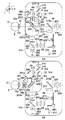
第一光学系200は、被検眼の眼屈折力を検査するための光学系である。波長880nmの光を照射する眼屈折力測定用光源201から被検眼Eに至る光路01上には、投影レンズ202、被検眼Eの瞳孔Epとほぼ共役な絞り203、孔あきミラー204、レンズ205が配置されている。また、被検眼E側から波長880nm以下の赤外および可視光を全反射し波長880nm以上の光束を一部反射するダイクロイックミラー206が順次に配置されている。   The first optical system 200 is an optical system for inspecting the eye refractive power of the eye to be examined. On the optical path 01 from the eye refractive power measurement light source 201 that irradiates light having a wavelength of 880 nm to the eye E, the projection lens 202, a diaphragm 203 that is substantially conjugate with the pupil Ep of the eye E, a perforated mirror 204, and a lens 205 Is arranged. Further, dichroic mirrors 206 are sequentially arranged to totally reflect infrared and visible light having a wavelength of 880 nm or less and partially reflect a light beam having a wavelength of 880 nm or more from the eye E side.

孔あきミラー204の反射方向の光路02上には、瞳孔Epとほぼ共役で円環状のスリットを備えた絞り207、光束分光プリズム208、レンズ209、撮像素子210が順次に配列されている。   On the optical path 02 in the reflection direction of the perforated mirror 204, a stop 207 having an annular slit substantially conjugate with the pupil Ep, a light beam splitting prism 208, a lens 209, and an image sensor 210 are sequentially arranged.

上述した光学系は眼屈折力測定用であり、眼屈折力測定用光源201から発せられた光束は、絞り203で光束が絞られる。そして、投影レンズ202によりレンズ205の手前で1次結像され、レンズ205、ダイクロイックミラー206を透過して被検眼Eの瞳中心に投光される。   The optical system described above is for measuring eye refractive power, and the light beam emitted from the light source 201 for measuring eye refractive power is narrowed by the diaphragm 203. Then, a primary image is formed in front of the lens 205 by the projection lens 202, and is transmitted through the lens 205 and the dichroic mirror 206 to be projected onto the pupil center of the eye E to be examined.

投光された光束の反射光は瞳中心を通って再びレンズ205に入射される。入射された光束はレンズ205を透過後に、孔あきミラー204の周辺で反射される。   The reflected light of the projected light beam is incident on the lens 205 again through the center of the pupil. The incident light beam is reflected around the perforated mirror 204 after passing through the lens 205.

反射された光束は被検眼瞳孔Epと略共役な絞り207および光束分光プリズム208で瞳分離され、撮像素子210の受光面にリング像として投影される。被検眼Eが正視眼であれば、このリング像は所定の円になり、近視眼では正視眼に対して円が小さく、遠視眼では正視眼に対して円が大きくなり投影される。被検眼Eに乱視がある場合、リング像は楕円になり、水平軸と楕円のなす角度が乱視軸角度となる。この楕円の係数を基に屈折力を求める。   The reflected light beam is pupil-separated by a stop 207 and a light beam spectroscopic prism 208 that are substantially conjugate to the eye pupil Ep to be examined, and projected onto the light receiving surface of the image sensor 210 as a ring image. If the eye E is a normal eye, the ring image is a predetermined circle. The myopic eye has a smaller circle than the normal eye, and the far-sighted eye has a larger circle and is projected. When the eye E has astigmatism, the ring image becomes an ellipse, and the angle between the horizontal axis and the ellipse becomes the astigmatism axis angle. The refractive power is obtained based on the coefficient of the ellipse.

一方、ダイクロイックミラー206の反射方向には、固視標投影光学系と、被検眼の前眼部観察とアライメント検出が共用されるアライメント受光光学系が配置されている。   On the other hand, in the reflection direction of the dichroic mirror 206, a fixation target projection optical system and an alignment light receiving optical system that shares anterior eye portion observation and alignment detection of the eye to be examined are arranged.

固視標投影光学系の光路03上には、レンズ211、ダイクロイックミラー212、レンズ213、折り返しミラー214、レンズ215、固視標216、固視標照明用光源217が順次に配列されている。   On the optical path 03 of the fixation target projection optical system, a lens 211, a dichroic mirror 212, a lens 213, a folding mirror 214, a lens 215, a fixation target 216, and a fixation target illumination light source 217 are sequentially arranged.

固視誘導時に、点灯された固視標照明用光源217の投影光束は、固視標216を裏側から照明する。そして、レンズ215、折り返しミラー214、レンズ213、ダイクロイックミラー212、レンズ211を介して被検眼Eの眼底Erに投影される。   At the time of fixation fixation, the projected light flux of the light source 217 for lighting the fixation target illuminates the fixation target 216 from the back side. Then, the light is projected onto the fundus Er of the eye E through the lens 215, the folding mirror 214, the lens 213, the dichroic mirror 212, and the lens 211.

なお、レンズ215は被検眼Eの視度誘導を行い雲霧状態を実現するために、固視標誘導モータ224により光軸方向に移動できるようになっている。   The lens 215 can be moved in the optical axis direction by a fixation target guidance motor 224 in order to guide the diopter of the eye E and realize a cloud state.

また、ダイクロイックミラー212の反射方向の光路04上には、アライメントプリズム絞り挿抜ソレノイド411により挿抜されるアライメントプリズム絞り223、結像レンズ218、撮像素子220が順次に配列されている。   On the optical path 04 in the reflection direction of the dichroic mirror 212, an alignment prism diaphragm 223, an imaging lens 218, and an image sensor 220 that are inserted / extracted by the alignment prism diaphragm insertion / extraction solenoid 411 are sequentially arranged.

アライメントプリズム絞り223の挿抜により、アライメントプリズム絞り223が光路04上にある時にはアライメントを、光路から退避しているときは前眼部観察または徹照観察を行うことができる。   By inserting / extracting the alignment prism diaphragm 223, alignment can be performed when the alignment prism diaphragm 223 is on the optical path 04, and anterior eye observation or transillumination observation can be performed when retracted from the optical path.

ここで、図3(a)にアライメントプリズム絞り223の形状を示す。円盤状の絞り板に3つの開口部223a、223b、223cが設けられ、開口部223a、223bのダイクロイックミラー212側には波長880nm付近のみの光束を透過するアライメントプリズム231a、231bが貼付されている。   Here, FIG. 3A shows the shape of the alignment prism diaphragm 223. Three apertures 223a, 223b, and 223c are provided in a disc-shaped diaphragm, and alignment prisms 231a and 231b that transmit light beams having a wavelength of only about 880 nm are attached to the dichroic mirror 212 side of the apertures 223a and 223b. .

また図2に戻ると、被検眼Eの前眼部の斜め前方には、780nm程度の波長を有する前眼部照明光源221a、221bが配置されている。前眼部照明光源221a、221bによって照明された被検眼Eの前眼部像の光束はダイクロイックミラー206、レンズ211、ダイクロイックミラー212、アライメントプリズム絞り中央の開口部223aを介して撮像素子220の受光センサ面に結像する。   Returning to FIG. 2, anterior segment illumination light sources 221 a and 221 b having a wavelength of about 780 nm are disposed obliquely in front of the anterior segment of the eye E. The luminous flux of the anterior segment image of the eye E illuminated by the anterior segment illumination light sources 221a and 221b is received by the image sensor 220 through the dichroic mirror 206, the lens 211, the dichroic mirror 212, and the opening 223a at the center of the alignment prism stop. An image is formed on the sensor surface.

アライメント検出のための光源は、眼屈折力測定用光源201と兼用されている。アライメント時には、拡散板挿抜ソレノイド410により半透明の拡散板222が光路に挿入される。   The light source for alignment detection is also used as the eye refractive power measurement light source 201. At the time of alignment, the translucent diffusion plate 222 is inserted into the optical path by the diffusion plate insertion / removal solenoid 410.

拡散板222が挿入される位置は、眼屈折力測定用光源201の投影レンズ202による略一次結像位置であり、かつレンズ205の焦点位置に挿入される。これにより、眼屈折力測定用光源201の像が拡散板222上に一旦結像して、それが二次光源となりレンズ205から被検眼Eに向かって太い光束の平行光束として投影される。   The position where the diffusing plate 222 is inserted is a substantially primary imaging position by the projection lens 202 of the eye refractive power measurement light source 201 and is inserted at the focal position of the lens 205. As a result, an image of the eye refractive power measurement light source 201 is once formed on the diffusion plate 222, which becomes a secondary light source and is projected from the lens 205 toward the eye E as a thick parallel light beam.

この平行光束が被検眼の角膜Efで反射されて輝点像を形成し、その光束は再びダイクロイックミラー206でその一部が反射される。そして、レンズ211を介してダイクロイックミラー212で反射し、アライメントプリズム絞りの開口部223aおよびアライメントプリズム231a、231bを透過し、結像レンズ218に収斂されて撮像素子220に結像される。   This parallel light beam is reflected by the cornea Ef of the eye to be examined to form a bright spot image, and a part of the light beam is again reflected by the dichroic mirror 206. Then, the light is reflected by the dichroic mirror 212 through the lens 211, passes through the opening 223 a of the alignment prism diaphragm and the alignment prisms 231 a and 231 b, converges on the imaging lens 218, and forms an image on the image sensor 220.

アライメントプリズム絞り223の中央の開口部223aは、前眼部照明光源221a、221bの波長780nm以上の光束が通るようになっている。前眼部照明光源221a、221bにより照明された前眼部像の反射光束は、角膜Efの反射光束の経路と同様に観察光学系を辿る。そして、アライメントプリズム絞り223の開口部223aを介して、結像レンズ218により撮像素子220に結像される。   Through the central opening 223a of the alignment prism diaphragm 223, a light beam having a wavelength of 780 nm or more of the anterior segment illumination light sources 221a and 221b passes. The reflected luminous flux of the anterior segment image illuminated by the anterior segment illumination light sources 221a and 221b follows the observation optical system in the same manner as the path of the reflected luminous flux of the cornea Ef. Then, the image is formed on the image sensor 220 by the imaging lens 218 through the opening 223 a of the alignment prism diaphragm 223.

また、アライメントプリズム231aを透過した光束は下方向に屈折され、アライメントプリズム231bを透過した光束は上方向に屈折される。これら絞りを介した光束の位置関係により被検眼Eのアライメントを行うことができる。   Further, the light beam transmitted through the alignment prism 231a is refracted downward, and the light beam transmitted through the alignment prism 231b is refracted upward. The eye E can be aligned based on the positional relationship of the light flux through these diaphragms.

一方、アライメントプリズム絞り223および角膜絞りを光路04から退避させた状態では、眼屈折力測定用光源201からの眼底Erでの反射光束により、照明された瞳孔領域の光束の一部はダイクロイックミラー206で反射される。レンズ211を介してダイクロイックミラー212で反射され、結像レンズ218により撮像素子220に投影される。この光束により被検眼Eの徹照観察を行うことができる。   On the other hand, in a state where the alignment prism diaphragm 223 and the corneal diaphragm are retracted from the optical path 04, a part of the light flux in the illuminated pupil region is reflected by the dichroic mirror 206 due to the light flux reflected on the fundus Er from the light source 201 for measuring eye refractive power. It is reflected by. The light is reflected by the dichroic mirror 212 via the lens 211 and projected onto the image sensor 220 by the imaging lens 218. The transillumination observation of the eye E can be performed with this light beam.

第二光学系300は、被検眼の眼圧を検査するための光学系である。被検眼Eに対する観察光学系の受光用光路及びアライメント検出用光路06上には、平行平面ガラス301と対物レンズ302の中心軸上にノズル303が配置されている。対物レンズ302の後方に空気室323、観察窓304、ダイクロイックミラー305、プリズム絞り306、結像レンズ307、撮像素子308が順次に配列されている。   The second optical system 300 is an optical system for examining the intraocular pressure of the eye to be examined. A nozzle 303 is disposed on the central axis of the plane-parallel glass 301 and the objective lens 302 on the light receiving optical path 06 and the alignment detecting optical path 06 of the observation optical system for the eye E. An air chamber 323, an observation window 304, a dichroic mirror 305, a prism diaphragm 306, an imaging lens 307, and an image sensor 308 are sequentially arranged behind the objective lens 302.

平行平面ガラス301、対物レンズ302は対物鏡筒309によって支持され、その外側には被検眼Eを照明する外眼照明光源310a、310bが配置されている。   The plane-parallel glass 301 and the objective lens 302 are supported by an objective barrel 309, and external eye illumination light sources 310a and 310b for illuminating the eye E are disposed on the outside thereof.

角膜Efが視軸方向に変形するときの変形検出受光光学系の光路07上には、ダイクロイックミラー305の反射方向に、リレーレンズ311、ハーフミラー312、アパーチャ313、受光素子314が配置されている。なお、アパーチャ313は、所定変形時に後述する眼圧測定用光源317の角膜反射像が共役になる位置に配置されている。   On the optical path 07 of the deformation detection light receiving optical system when the cornea Ef is deformed in the visual axis direction, a relay lens 311, a half mirror 312, an aperture 313, and a light receiving element 314 are arranged in the reflection direction of the dichroic mirror 305. . The aperture 313 is disposed at a position where a cornea reflection image of an intraocular pressure measurement light source 317, which will be described later, is conjugated at the time of predetermined deformation.

リレーレンズ311は角膜Ecが所定変形時にアパーチャ313とほぼ同等の大きさの角膜反射像を結像するように設計されている。   The relay lens 311 is designed to form a corneal reflection image having a size substantially equal to that of the aperture 313 when the cornea Ec is deformed to a predetermined degree.

角膜Efの変形を測定するための測定光源投影光学系の光路05上には、ハーフミラー312の入射方向に、ハーフミラー315、投影レンズ316が配置されている。更に、測定及び被検眼Eに対するアライメント兼用の近赤外LEDから成る眼圧測定用光源317が配置されている。またハーフミラー315の入射方向には、被検者が固視するLEDから構成される固視用光源318が配置されている。   A half mirror 315 and a projection lens 316 are arranged in the incident direction of the half mirror 312 on the optical path 05 of the measurement light source projection optical system for measuring the deformation of the cornea Ef. Further, a light source 317 for measuring intraocular pressure composed of a near-infrared LED that is used for both measurement and alignment with the eye E is disposed. Further, in the incident direction of the half mirror 315, a fixation light source 318 configured by an LED fixed by the subject is disposed.

空気室323内にはその一部を構成する対物鏡筒309にピストン320が嵌合され、このピストン320はソレノイド322によって駆動されるようになっている。なお、空気室323内には、内圧をモニタするための圧力センサ324が配置されている。   In the air chamber 323, a piston 320 is fitted into an objective barrel 309 constituting a part thereof, and the piston 320 is driven by a solenoid 322. Note that a pressure sensor 324 for monitoring the internal pressure is disposed in the air chamber 323.

(外形寸法)
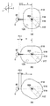
図4は、検眼ユニット110の平面図である。図4(a)は、第一光学系200による眼屈折力測定時の検眼ユニット110と被検眼Eとの位置関係を示す。図4(b)は、第二光学系300による眼圧測定時の検眼ユニット110と被検眼Eとの位置関係を示している。第一光学系200による眼屈折力測定時の作動距離、つまり被検眼Eの角膜頂点Efから検眼ユニット110の第一光学系出力側端部までの距離をWD1とし、回転中心350から検眼ユニット110の第一光学系出力側端部までの距離をAとする。また第二光学系300による眼圧測定時の作動距離、つまり被検眼Eの角膜頂点Efから検眼ユニット110の第二光学系出力側端部までの距離をWD2とし、回転中心350から検眼ユニット110の第二光学系出力側端部までの距離をBとする。このとき、WD1+A=WD2+Bとなるように、検眼ユニット110及び回転中心350は構成されている。また、図4(c)は、回転移動中の検眼ユニット110と被検眼Eとの位置関係を表している。第一光学系及び第二光学系出力側端部以外の検眼ユニット110の外形寸法は、回転中心350からの外形寸法Cが回転移動時に被検者の突出部との接触がない距離WD3を保つように、構成されている。
(External dimensions)
FIG. 4 is a plan view of the optometry unit 110. FIG. 4A shows the positional relationship between the optometry unit 110 and the eye E during eye refractive power measurement by the first optical system 200. FIG. 4B shows a positional relationship between the optometry unit 110 and the eye E when the intraocular pressure is measured by the second optical system 300. The working distance when the eye refractive power is measured by the first optical system 200, that is, the distance from the corneal apex Ef of the eye E to the first optical system output side end of the optometry unit 110 is set as WD1, and the optometry unit 110 from the rotation center 350. Let A be the distance to the first optical system output side end. Further, the working distance at the time of intraocular pressure measurement by the second optical system 300, that is, the distance from the corneal apex Ef of the eye E to the second optical system output side end of the optometry unit 110 is WD2, and the optometry unit 110 from the rotation center 350 Let B be the distance to the second optical system output side end. At this time, the optometry unit 110 and the rotation center 350 are configured such that WD1 + A = WD2 + B. FIG. 4C shows the positional relationship between the optometry unit 110 and the eye E under rotation. The external dimensions of the optometry unit 110 other than the first optical system and the second optical system output side end are maintained at a distance WD3 where the external dimension C from the rotation center 350 is not in contact with the protrusion of the subject when rotating. It is configured as such.

(システムブロック図)
図5は眼科装置のシステムブロック図である。システム制御部401はシステム全体を制御している。システム制御部401は、プログラム格納部、眼圧値、眼屈折力値等を補正するためのデータが格納されたデータ格納部を有する。また、システム制御部401は、各種デバイスとの入出力を制御する入出力制御部、および各種デバイスから得られたデータを演算する演算処理部を有している。
(System block diagram)
FIG. 5 is a system block diagram of the ophthalmologic apparatus. A system control unit 401 controls the entire system. The system control unit 401 includes a program storage unit, a data storage unit that stores data for correcting an intraocular pressure value, an eye refractive power value, and the like. The system control unit 401 also includes an input / output control unit that controls input / output with various devices, and an arithmetic processing unit that calculates data obtained from the various devices.

システム制御部401には、傾倒角度入力部402、エンコーダ入力部403、測定開始信号入力部404が接続されている。検眼ユニット110を被検眼Eに位置合わせおよび測定開始を行うためのジョイスティック101からの指示(信号)は、傾倒角度入力部402、エンコーダ入力部403、測定開始信号入力部404を介して、システム制御部401に入力される。傾倒角度入力部402はジョイスティック101を前後左右に傾けたときの傾倒角度を検出し、検出した傾倒角度をシステム制御部401に入力する。エンコーダ入力部403は、ジョイスティック101の操作により各種の駆動モータを回転させたときの各種の駆動モータからのエンコーダ信号を受け付け、システム制御部401に入力する。測定開始信号入力部404はジョイスティック101の測定開始釦押下時の信号を受け付け、システム制御部401に入力する。   A tilt angle input unit 402, an encoder input unit 403, and a measurement start signal input unit 404 are connected to the system control unit 401. An instruction (signal) from the joystick 101 for aligning the optometry unit 110 with the eye E and starting measurement is controlled by the system via the tilt angle input unit 402, encoder input unit 403, and measurement start signal input unit 404. Input to the unit 401. The tilt angle input unit 402 detects the tilt angle when the joystick 101 is tilted forward, backward, left and right, and inputs the detected tilt angle to the system control unit 401. The encoder input unit 403 receives encoder signals from various drive motors when various drive motors are rotated by operating the joystick 101, and inputs them to the system control unit 401. The measurement start signal input unit 404 receives a signal when the measurement start button of the joystick 101 is pressed and inputs the signal to the system control unit 401.

また、ベース100上の操作パネル405には、印字釦や顎受上下釦などが配置されており、釦入力時にシステム制御部401に信号が通知される。さらに位置検出センサ133(a)、(b)、(c)(検出部)を含めた各種の位置検出センサ406からの信号は、センサON時にシステム制御部401に通知される。   The operation panel 405 on the base 100 is provided with a print button, a chin rest up / down button, and the like, and a signal is notified to the system control unit 401 when the button is input. Further, signals from various position detection sensors 406 including the position detection sensors 133 (a), (b), and (c) (detection unit) are notified to the system control unit 401 when the sensors are turned on.

撮像素子220で撮像された被検眼Eの前眼部像は、メモリ408に格納される。システム制御部401は、メモリ408に格納された画像から被検眼Eの瞳孔と角膜反射像を抽出しアライメント検出を行う。また、撮像素子220で撮像された被検眼Eの前眼部像は、文字,図形データと合成され、LCDモニタ(表示部109)上に前眼部像や測定値などが表示される。   An anterior segment image of the eye E to be examined captured by the image sensor 220 is stored in the memory 408. The system control unit 401 extracts the pupil and corneal reflection image of the eye E from the image stored in the memory 408, and performs alignment detection. In addition, the anterior segment image of the eye E to be examined captured by the image sensor 220 is combined with character and graphic data, and the anterior segment image, measurement values, and the like are displayed on the LCD monitor (display unit 109).

撮像素子210で撮影された眼屈折力算出用リング像はメモリ408に格納される。   The eye refractive power calculation ring image photographed by the image sensor 210 is stored in the memory 408.

410〜412の各ソレノイドは、ソレノイド駆動回路409を介して、システム制御部401からの指令により駆動制御される。   The solenoids 410 to 412 are driven and controlled by a command from the system control unit 401 via a solenoid driving circuit 409.

また、X軸駆動モータ103、Y軸駆動モータ104、Z軸駆動モータ105、顎受駆動モータ113、Θ軸駆動モータ116、顔支持駆動モータ131、固視標誘導モータ224は、モータ駆動回路414と接続している。モータ駆動回路414は、システム制御部401からの指令を受け付け、各種のモータを駆動する。   Further, the X-axis drive motor 103, the Y-axis drive motor 104, the Z-axis drive motor 105, the chin rest drive motor 113, the Θ-axis drive motor 116, the face support drive motor 131, and the fixation target induction motor 224 are a motor drive circuit 414. Connected. The motor drive circuit 414 receives commands from the system control unit 401 and drives various motors.

眼屈折力測定用光源201、眼屈折力測定用の前眼部照明光源221a,221b、固視標照明用光源217、眼圧測定用光源317、固視用光源318、眼圧測定用の外眼照明光源310a,310bは光源駆動回路413と接続する。光源駆動回路413は、システム制御部401からの指令を受け付け、各種の光源の点灯、消灯、光量変更を制御する。   Eye refractive power measurement light source 201, anterior eye illumination light source 221a, 221b for eye refractive power measurement, fixation target illumination light source 217, intraocular pressure measurement light source 317, fixation light source 318, outside of intraocular pressure measurement The eye illumination light sources 310 a and 310 b are connected to a light source driving circuit 413. The light source driving circuit 413 receives a command from the system control unit 401 and controls turning on / off and changing the light amount of various light sources.

以上のような構成を備える装置における動作を説明する。   The operation of the apparatus having the above configuration will be described.

(眼屈折力測定)
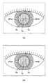
図6(a)に示すようにアライメント時には、角膜Efによって結像した角膜輝点はアライメントプリズム絞り223の開口部223a、223b、223cおよびアライメントプリズム231a、231bにより分割される。そして、角膜輝点は、前眼部照明光源221a、221bによって照明された被検眼Eと、前眼部照明光源221a、221bの輝点像221a’、221b’とともに、撮像素子220で指標像Ta、Tb、Tcとして撮像される。
(Eye refractive power measurement)
As shown in FIG. 6A, at the time of alignment, the corneal bright spots formed by the cornea Ef are divided by the openings 223a, 223b, and 223c of the alignment prism diaphragm 223 and the alignment prisms 231a and 231b. The corneal bright spot is detected by the imaging element 220 together with the eye E to be examined illuminated by the anterior segment illumination light sources 221a and 221b and the bright spot images 221a ′ and 221b ′ of the anterior segment illumination light sources 221a and 221b. , Tb, and Tc.

アライメントは、粗い位置合わせを行うラフアライメントと、精密な位置合わせを行うファインアライメントの2段階で実施する。   Alignment is performed in two stages: rough alignment for rough alignment and fine alignment for precise alignment.

ラフアライメントには被検眼Eと前眼部照明光源221a、221bの輝点像221a’、221b’を使用する。被検眼E及び輝点像221a’、221b’が検出できると、システム制御部401はモータ駆動回路414を制御する。そして、システム制御部401は、被検眼Eの瞳孔中心に対し輝点像221a’、221b’をXY方向に一致させるように検眼ユニット110を上下左右方向に駆動させる。   The rough alignment uses the eye E and the bright spot images 221a 'and 221b' of the anterior illumination light sources 221a and 221b. When the eye E and the bright spot images 221a 'and 221b' can be detected, the system control unit 401 controls the motor drive circuit 414. Then, the system control unit 401 drives the optometry unit 110 in the vertical and horizontal directions so that the bright spot images 221a 'and 221b' coincide with the XY direction with respect to the pupil center of the eye E.

次に、システム制御部401は輝点像221a’、221b’のZ座標及び面積を算出し、それらを所定の位置に合わせるようにさらに検眼ユニット110を前後方向に駆動させることによって粗い位置合わせを行う。   Next, the system control unit 401 calculates the Z coordinates and areas of the bright spot images 221a ′ and 221b ′, and further drives the optometry unit 110 in the front-rear direction so as to match them to a predetermined position, thereby performing rough alignment. Do.

ファインアライメントには指標像Ta、Tb、Tcを使用する。3つの輝点Ta、Tb、Tcが検出できると、システム制御部401はモータ駆動回路414を制御する。そして、システム制御部401は、中央の輝点Tcを被検眼Eの中心に一致させるように検眼ユニット110を上下左右方向に駆動させる。次に、システム制御部401は輝点Ta、Tbが輝点Tcに対して鉛直方向に並ぶようさらに検眼ユニット110を前後方向に駆動させ、3つの角膜輝点Ta、Tb、Tcが上下方向に1列に並んだ状態でアライメントを完了する。   Index images Ta, Tb, and Tc are used for fine alignment. When the three bright spots Ta, Tb, and Tc can be detected, the system control unit 401 controls the motor drive circuit 414. Then, the system control unit 401 drives the optometry unit 110 in the vertical and horizontal directions so that the central bright spot Tc coincides with the center of the eye E to be examined. Next, the system control unit 401 further drives the optometry unit 110 in the front-rear direction so that the bright spots Ta and Tb are aligned in the vertical direction with respect to the bright spot Tc, so that the three corneal bright spots Ta, Tb, and Tc are in the vertical direction. Alignment is completed in a state of being aligned in one row.

眼屈折力を測定するために、システム制御部401はオートアライメントのために光路01に挿入していた拡散板222を光路01から退避させる。眼屈折力測定用光源201の光量を調整し、被検眼Eの眼底Erに測定光束を投影する。   In order to measure the eye refractive power, the system control unit 401 retracts the diffusion plate 222 inserted in the optical path 01 for auto-alignment from the optical path 01. The light amount of the eye refractive power measurement light source 201 is adjusted, and the measurement light beam is projected onto the fundus Er of the eye E to be examined.

眼底からの反射光は光路02を辿り、撮像素子210で受光される。撮像された眼底像は被検眼の屈折力により、リング絞り207により、リング状に投影される。このリング像はメモリ408に格納される。   Reflected light from the fundus follows the optical path 02 and is received by the image sensor 210. The captured fundus image is projected in a ring shape by the ring diaphragm 207 by the refractive power of the eye to be examined. This ring image is stored in the memory 408.

メモリ408に格納されたリング像の重心座標を算出し、周知の方法により楕円の方程式を求める。求められた楕円の長径と短径および長径軸の傾きを算出して、被検眼Eの眼屈折力を算出する。   The center-of-gravity coordinates of the ring image stored in the memory 408 are calculated, and an elliptic equation is obtained by a known method. The inclination of the major axis, minor axis, and major axis of the obtained ellipse is calculated, and the eye refractive power of the eye E is calculated.

なお、求められた楕円の長径、短径に相当する眼屈折力値および撮像素子210の受光面上での楕円軸の角度と乱視軸との関係は、予め装置の製造工程において矯正されている。   The relationship between the obtained ocular refractive power value corresponding to the major axis and minor axis of the ellipse and the angle of the ellipse axis on the light receiving surface of the image sensor 210 and the astigmatism axis is corrected in advance in the manufacturing process of the apparatus. .

求められた眼屈折力値からその屈折力値に相当する位置まで、モータ駆動回路414を介して固視標誘導モータ224を駆動し、レンズ215を移動して、被検眼Eの屈折度に相当する屈折度で固視標216を被検眼Eに呈示する。   The fixation target induction motor 224 is driven via the motor drive circuit 414 from the obtained eye refractive power value to a position corresponding to the refractive power value, and the lens 215 is moved to correspond to the refractive power of the eye E to be examined. The fixation target 216 is presented to the eye E with the degree of refraction.

その後、レンズ215を所定量だけ遠方に移動し、固視標216を雲霧させ、再び測定光源を点灯し屈折力を測定する。このように、屈折力の測定→固視標216による雲霧→屈折力の測定を繰り返し、屈折力が安定する最終の測定値を得ることができる。   Thereafter, the lens 215 is moved away by a predetermined amount, the fixation target 216 is fogged, the measurement light source is turned on again, and the refractive power is measured. In this way, measurement of refractive power → cloud fog using the fixation target 216 → measurement of refractive power can be repeated to obtain a final measurement value in which the refractive power is stabilized.

(眼圧測定)
図6(b)に示すように眼圧測定のアライメント時には、角膜Efによって結像した角膜輝点は図3(b)に示したアライメントプリズム絞り306の開口部306a、306b、306cおよびプリズム232a、232bにより分割される。そして、角膜輝点は、外眼照明光源310a、310bによって照明された被検眼Eと、外眼照明光源310a、310bの輝点像310a’、310b’とともに、撮像素子308で指標像Ta、Tb、Tcとして撮像される。以下は、眼屈折力測定のアライメント時と同様である。
(Intraocular pressure measurement)
As shown in FIG. 6B, at the time of alignment of tonometry, the corneal bright spots formed by the cornea Ef are the openings 306a, 306b, 306c and the prism 232a of the alignment prism diaphragm 306 shown in FIG. It is divided by H.232b. The corneal bright spots are detected by the image sensor 308 together with the index images Ta and Tb together with the eye E to be examined illuminated by the external illumination light sources 310a and 310b and the bright spot images 310a ′ and 310b ′ of the external illumination light sources 310a and 310b. , Tc. The following is the same as the alignment for the eye refractive power measurement.

アライメントの完了後に眼圧測定を行う。システム制御部401はソレノイド322を駆動し、空気室323内の空気はソレノイド322により押し上げられるピストン320によって圧縮され、パルス状の空気としてノズル303から被検眼Eの角膜Efに向けて噴出する。   Measure intraocular pressure after alignment is complete. The system control unit 401 drives the solenoid 322, and the air in the air chamber 323 is compressed by the piston 320 pushed up by the solenoid 322, and is ejected from the nozzle 303 toward the cornea Ef of the eye E as pulsed air.

空気室323の圧力センサ324で検出された圧力信号と受光素子314からの受光信号はシステム制御部401に出力され、システム制御部401は受光信号のピーク値とその時の圧力信号から眼圧値を算出する。   The pressure signal detected by the pressure sensor 324 of the air chamber 323 and the light reception signal from the light receiving element 314 are output to the system control unit 401, and the system control unit 401 calculates the intraocular pressure value from the peak value of the light reception signal and the pressure signal at that time. calculate.

(自動運転を行う際の動作説明)
以上のような構成を持つ眼科装置において、検眼時の動作として自動運転を行う際の動作を図7のフローチャート、図8の動作説明図に基づいて説明する。
(Explanation of operation when performing automatic operation)
In the ophthalmologic apparatus having the above-described configuration, the operation at the time of performing automatic driving as the operation at the time of optometry will be described based on the flowchart of FIG. 7 and the operation explanatory diagram of FIG.

検者140が電源をONにして眼科装置を立ち上げると、眼科装置は各種デバイスの初期化を行なう。最初に被検者の右目E(R)の眼屈折力測定を行うために、被検者150の右被検眼E(R)に対して検眼ユニット110が眼屈折力測定を行う位置に移動して準備完了となる。この状態から、検者140は被検者150の顎を顎受け112に積載させ、額受け部(不図示)に被検者150の額を当てることで、被検眼Eを固定させる。次に、検者140はLCDモニタ(表示部109)上のスイッチ(不図示)にて、全自動(フルオート)モードを選択する。そして、検者140は必要に応じてジョイスティック101を傾倒動作させてLCDモニタ(表示部109)の観察範囲内に被検眼E(R)の瞳孔中心が入っている状態にする。この状態から測定開始釦121を押すことにより自動測定が開始される。   When the examiner 140 turns on the power and starts up the ophthalmologic apparatus, the ophthalmologic apparatus initializes various devices. First, in order to measure the eye refractive power of the right eye E (R) of the subject, the optometry unit 110 moves to the position where the eye refractive power measurement of the right eye E (R) of the subject 150 is performed. Ready. From this state, the examiner 140 loads the chin of the subject 150 on the chin rest 112 and fixes the eye E by applying the forehead of the subject 150 to the forehead receiving portion (not shown). Next, the examiner 140 selects a fully automatic mode with a switch (not shown) on the LCD monitor (display unit 109). Then, the examiner 140 tilts the joystick 101 as necessary so that the pupil center of the eye E (R) is within the observation range of the LCD monitor (display unit 109). By pressing the measurement start button 121 from this state, automatic measurement is started.

測定開始釦121が押されると、まず眼屈折力測定のための粗い位置合わせであるラフアライメントが開始される(S100)。ラフアライメント完了(S101)後、より精密な位置合わせであるファインアライメントが開始される(S102)。   When the measurement start button 121 is pressed, rough alignment, which is rough alignment for eye refractive power measurement, is started (S100). After the rough alignment is completed (S101), fine alignment, which is more precise alignment, is started (S102).

ファインアライメント完了(S103)後、被検者の右目E(R)の眼屈折力測定を所定回数分行う(S104及び図8(a):右目・第一検眼)。右被検眼の眼屈折力測定後、検眼ユニット110をX及びZ方向に必要量だけ移動させ、被検者の左被検眼E(L)の眼屈折力測定を所定回数分行う(S105及び図8(b):左目・第一検眼)。眼屈折力測定を所定回数分行うまでS100〜S105の処理が繰り返される(S106−No)。左右眼の眼屈折力測定を所定回数分完了した後(S106−Yes)、眼屈折力測定から眼圧測定への検眼切替の為に、検眼ユニット110をΘ方向に移動させる(S107)。このとき、検眼ユニット110は、被検者の突出部(例えば鼻)に接触することがないように、回転移動を行う。具体的には、被検者の左耳側から鼻側に向かって検眼ユニット110の眼圧測定光学系の出力側端部を回転移動させる(図8(c))。これにより、被検者の突出部との干渉を防止しながら、Θ軸1軸のみによる素早い切替動作が可能となる。また切替はΘ軸1軸による回転動作のみで、かつ回転中心から被検眼Eまでの距離は一定なので、切替後の検眼ユニット110のXY方向位置は再現され、眼圧測定に必要なZ方向の作動距離が自動的に得られる。よって切替後のラフアライメントを行う必要はなくなり、さらなる検眼時間の短縮が可能となる。切替後は被検者の左被検眼E(L)のファインアライメントを開始する(S108)。ファインアライメント完了後(S109)、左被検眼E(L)の眼圧測定を所定回数分行う(S110、図8(c):左目・第二検眼)。   After the fine alignment is completed (S103), the eye refractive power of the subject's right eye E (R) is measured a predetermined number of times (S104 and FIG. 8 (a): right eye / first eye examination). After measuring the eye refractive power of the right eye, the optometry unit 110 is moved by a necessary amount in the X and Z directions, and the eye refractive power of the left eye E (L) of the subject is measured a predetermined number of times (S105 and FIG. 8 (b): Left eye / first optometry). The processes of S100 to S105 are repeated until the eye refractive power measurement is performed a predetermined number of times (S106-No). After the eye refractive power measurement of the left and right eyes is completed a predetermined number of times (S106-Yes), the optometry unit 110 is moved in the Θ direction for switching the optometry from the eye refractive power measurement to the intraocular pressure measurement (S107). At this time, the optometry unit 110 performs rotational movement so as not to contact the protrusion (for example, the nose) of the subject. Specifically, the output side end portion of the intraocular pressure measurement optical system of the optometry unit 110 is rotated from the left ear side to the nose side of the subject (FIG. 8C). As a result, it is possible to perform a quick switching operation using only one Θ axis while preventing interference with the protrusion of the subject. Further, since the switching is only a rotation operation by the Θ axis 1 and the distance from the rotation center to the eye E is constant, the XY direction position of the optometry unit 110 after the switching is reproduced, and the Z direction necessary for the intraocular pressure measurement is reproduced. The working distance is obtained automatically. Therefore, it is not necessary to perform rough alignment after switching, and the optometry time can be further shortened. After switching, fine alignment of the left eye E (L) of the subject is started (S108). After the fine alignment is completed (S109), the intraocular pressure of the left eye E (L) is measured a predetermined number of times (S110, FIG. 8 (c): left eye / second eye examination).

左被検眼E(L)の眼圧測定完了後、検眼ユニット110をX及びZ方向に必要量だけ移動させ、右被検眼E(R)の眼圧測定を所定回数分行う(S111、図8(d):右目・第二検眼)。眼圧測定を所定回数分行うまでS108〜S111の処理が繰り返される(S112−No)。左右眼の眼圧測定を所定回数分完了すると(S112−Yes)、検査完了となる。   After the intraocular pressure measurement of the left eye E (L) is completed, the optometry unit 110 is moved by a necessary amount in the X and Z directions, and the intraocular pressure measurement of the right eye E (R) is performed a predetermined number of times (S111, FIG. 8). (D): Right eye / second optometry). The processes of S108 to S111 are repeated until the intraocular pressure measurement is performed a predetermined number of times (S112—No). When the intraocular pressure measurement for the left and right eyes is completed a predetermined number of times (S112—Yes), the inspection is completed.

(第2実施形態)
図9は、眼屈折力測定を左被検眼から開始した場合の第2実施形態の説明図である。この場合、左被検眼E(L)、右被検眼E(R)の順番で眼屈折力測定後(図9(a)、(b))、眼屈折力測定から眼圧測定への検眼切替の為に、検眼ユニット110をΘ方向に移動させる。この切替動作時に、システム制御部401は、被検者の突出部(例えば鼻)に検眼ユニット110が当らないように、眼圧測定光学系の出力側端部が右耳側から鼻側に向かって移動するように検眼ユニット110を回転させる。これにより、被検者の突出部との干渉を防止しながら、Θ軸1軸のみによる素早い切替動作が可能となる。また切替はΘ軸1軸による回転動作のみで、かつ回転中心から被検眼Eまでの距離は一定なので、切替後の検眼ユニット110のXY方向位置は再現され、眼圧測定に必要なZ方向の作動距離が自動的に得られる。よって切替後のラフアライメントを行う必要はなくなり、さらなる検眼時間の短縮が可能となる。切替後は被検者の右被検眼E(R)のファインアライメントを開始する。ファインアライメント完了後、右被検眼E(R)の眼圧測定を所定回数分行う(図9(c))。右被検眼E(R)の眼圧測定完了後、検眼ユニット110をX及びZ方向に必要量だけ移動させ、左被検眼E(L)の眼圧測定を所定回数分行う(図9(d))。
(Second Embodiment)
FIG. 9 is an explanatory diagram of the second embodiment when the eye refractive power measurement is started from the left eye. In this case, after the eye refractive power is measured in the order of the left eye E (L) and the right eye E (R) (FIGS. 9A and 9B), the optometric switching from the eye refractive power measurement to the intraocular pressure measurement is performed. Therefore, the optometry unit 110 is moved in the Θ direction. During this switching operation, the system control unit 401 moves the output side end of the tonometry optical system from the right ear side to the nose side so that the optometry unit 110 does not hit the protrusion (for example, the nose) of the subject. The optometry unit 110 is rotated so as to move. As a result, it is possible to perform a quick switching operation using only one Θ axis while preventing interference with the protrusion of the subject. Further, since the switching is only a rotation operation by the Θ axis 1 and the distance from the rotation center to the eye E is constant, the XY direction position of the optometry unit 110 after the switching is reproduced, and the Z direction necessary for the intraocular pressure measurement is reproduced. The working distance is obtained automatically. Therefore, it is not necessary to perform rough alignment after switching, and the optometry time can be further shortened. After switching, fine alignment of the subject's right eye E (R) is started. After the fine alignment is completed, the intraocular pressure of the right eye E (R) is measured a predetermined number of times (FIG. 9 (c)). After completion of the intraocular pressure measurement of the right eye E (R), the optometry unit 110 is moved by a necessary amount in the X and Z directions, and the intraocular pressure measurement of the left eye E (L) is performed a predetermined number of times (FIG. 9 (d) )).

(第3実施形態)
第3実施形態にかかる眼科装置の構成を図10を用いて説明する。本実施形態では、検眼ユニット110全体ではなく、検眼ユニット110の一部を構成する回転ユニット251(切替部)を回転させることで、検査の切替を行う構成を説明する。回転ユニット251(切替部)は、第一検眼部および第二検眼部で共通に使用する光学素子(例えば、ダイクロイックミラー252等)を含み、被検眼に対する切替光学素子部の向きを変更することで、第一検眼部または第二検眼部の切替が可能である。検眼ユニット110は、被検眼に対して接近または後退する方向(Z方向)に移動可能なフレーム107上に固定されている。回転ユニット251は、検眼ユニット110上に固定されたΘ軸駆動モータ116(駆動部)の出力軸に連結されており、検眼ユニット110に対する回転軸回り(Θ軸方向)に回転移動することが可能な構成となっている。尚、図10の構成では、検眼ユニット110は、フレーム107上に固定されている例を示しているが、本発明の趣旨はこの例に限定されるものではない。例えば、図1に示すように検眼ユニット110がフレーム107に対して回転可能なように構成することも可能である。
(Third embodiment)
The configuration of the ophthalmologic apparatus according to the third embodiment will be described with reference to FIG. In the present embodiment, a configuration is described in which examination switching is performed by rotating a rotation unit 251 (switching unit) that constitutes a part of the optometry unit 110 instead of the entire optometry unit 110. The rotation unit 251 (switching unit) includes an optical element (for example, a dichroic mirror 252) that is commonly used by the first optometry unit and the second optometry unit, and changes the direction of the switching optical element unit with respect to the eye to be examined. Thus, switching between the first optometry unit or the second optometry unit is possible. The optometry unit 110 is fixed on a frame 107 that can move in a direction (Z direction) that approaches or retracts from the eye to be examined. The rotation unit 251 is connected to the output shaft of the Θ-axis drive motor 116 (drive unit) fixed on the optometry unit 110, and can rotate around the rotation axis (Θ-axis direction) with respect to the optometry unit 110. It has become a structure. 10 shows an example in which the optometry unit 110 is fixed on the frame 107, the gist of the present invention is not limited to this example. For example, as shown in FIG. 1, the optometry unit 110 can be configured to be rotatable with respect to the frame 107.

図11は、図10に示した検眼ユニット110内の光学系の構成図である。   FIG. 11 is a configuration diagram of an optical system in the optometry unit 110 shown in FIG.

(第一光学系)
図11(a)は、眼屈折力測定時の検眼ユニット110内の光学系の構成図である。波長880nmの光を照射する眼屈折力測定用光源201から被検眼Eに至る光路01上には、投影レンズ202、被検眼Eの瞳孔Epとほぼ共役な絞り203、孔あきミラー204、レンズ205が配置されている。また、被検眼E側から波長880nm以下の赤外および可視光を一部反射し波長880nm以上の光束を全反射するダイクロイックミラー252が順次に配置されている。ダイクロイックミラー252は回転ユニット251内に配置されている。孔あきミラー204の反射方向の光路02上には、瞳孔Epとほぼ共役で円環状のスリットを備えた絞り207、光束分光プリズム208、レンズ209、撮像素子210が順次に配列されている。
(First optical system)
FIG. 11A is a configuration diagram of an optical system in the optometry unit 110 at the time of eye refractive power measurement. On the optical path 01 from the eye refractive power measurement light source 201 that irradiates light having a wavelength of 880 nm to the eye E, the projection lens 202, a diaphragm 203 that is substantially conjugate with the pupil Ep of the eye E, a perforated mirror 204, and a lens 205 Is arranged. Further, dichroic mirrors 252 that partially reflect infrared and visible light having a wavelength of 880 nm or less and totally reflect a light beam having a wavelength of 880 nm or more from the eye E side are sequentially arranged. The dichroic mirror 252 is disposed in the rotation unit 251. On the optical path 02 in the reflection direction of the perforated mirror 204, a stop 207 having an annular slit substantially conjugate with the pupil Ep, a light beam splitting prism 208, a lens 209, and an image sensor 210 are sequentially arranged.

上述した光学系は眼屈折力測定用であり、眼屈折力測定用光源201から発せられた光束は、絞り203で光束が絞られる。そして、投影レンズ202によりレンズ205の手前で1次結像され、レンズ205を透過、ダイクロイックミラー252で反射して被検眼Eの瞳中心に投光される。投光された光束の反射光は瞳中心を通って再びレンズ205に入射される。入射された光束はレンズ205を透過後に、孔あきミラー204の周辺で反射される。   The optical system described above is for measuring eye refractive power, and the light beam emitted from the light source 201 for measuring eye refractive power is narrowed by the diaphragm 203. Then, the primary image is formed in front of the lens 205 by the projection lens 202, transmitted through the lens 205, reflected by the dichroic mirror 252, and projected onto the pupil center of the eye E to be examined. The reflected light of the projected light beam is incident on the lens 205 again through the center of the pupil. The incident light beam is reflected around the perforated mirror 204 after passing through the lens 205.

反射された光束は被検眼瞳孔Epと略共役な絞り207および光束分光プリズム208で瞳分離され、撮像素子210の受光面にリング像として投影される。一方、ダイクロイックミラー206の透過方向には、固視標投影光学系と、被検眼の前眼部観察とアライメント検出が共用されるアライメント受光光学系が配置されている。   The reflected light beam is pupil-separated by a stop 207 and a light beam spectroscopic prism 208 that are substantially conjugate to the eye pupil Ep to be examined, and projected onto the light receiving surface of the image sensor 210 as a ring image. On the other hand, in the transmission direction of the dichroic mirror 206, a fixation target projection optical system and an alignment light receiving optical system that shares anterior eye portion observation and alignment detection of the eye to be examined are arranged.

固視標投影光学系の光路03上には、ダイクロイックミラー214a、レンズ213、レンズ215、固視標216、固視標照明用光源217が順次に配列されている。   On the optical path 03 of the fixation target projection optical system, a dichroic mirror 214a, a lens 213, a lens 215, a fixation target 216, and a fixation target illumination light source 217 are sequentially arranged.

固視誘導時に、点灯された固視標照明用光源217の投影光束は、固視標216を裏側から照明し、レンズ215、レンズ213、ダイクロイックミラー214aを介して被検眼Eの眼底Erに投影される。   At the time of fixation fixation, the projected luminous flux of the fixation target illumination light source 217 illuminates the fixation target 216 from the back side and projects it onto the fundus Er of the eye E through the lens 215, the lens 213, and the dichroic mirror 214a. Is done.

なお、レンズ215は被検眼Eの視度誘導を行い雲霧状態を実現するために、固視標誘導モータ224により光軸方向に移動できるようになっている。   The lens 215 can be moved in the optical axis direction by a fixation target guidance motor 224 in order to guide the diopter of the eye E and realize a cloud state.

また、ダイクロイックミラー214aの透過方向の光路04上には、アライメントプリズム絞り挿抜ソレノイド411により挿抜されるアライメントプリズム絞り223、結像レンズ218、撮像素子220が順次に配列されている。アライメントプリズム絞り223の挿抜により、アライメントプリズム絞り223が光路04上にある時にはアライメントを、光路から退避しているときは前眼部観察または徹照観察を行うことができる。   On the optical path 04 in the transmission direction of the dichroic mirror 214a, an alignment prism diaphragm 223, an imaging lens 218, and an image sensor 220 that are inserted / extracted by the alignment prism diaphragm insertion / extraction solenoid 411 are sequentially arranged. By inserting / extracting the alignment prism diaphragm 223, alignment can be performed when the alignment prism diaphragm 223 is on the optical path 04, and anterior eye observation or transillumination observation can be performed when retracted from the optical path.

(第二光学系)
図11(b)は、眼圧測定時の検眼ユニット110内の光学系の構成図である。被検眼Eに対する観察光学系の受光用光路およびアライメント検出用光路04上には、平行平面ガラス301と対物レンズ302の中心軸上にノズル303が配置されている。対物レンズ302の後方に空気室323、観察窓304、ダイクロイックミラー252、ダイクロイックミラー214a、プリズム絞り223、結像レンズ218、撮像素子220が順次に配列されている。平行平面ガラス301、対物レンズ302は対物鏡筒309によって支持され、その外側には被検眼Eを照明する外眼照明光源として機能する光源(221a、221b)が配置されている。
(Second optical system)
FIG. 11B is a configuration diagram of an optical system in the optometry unit 110 at the time of measuring intraocular pressure. On the light receiving optical path 04 and the alignment detecting optical path 04 of the observation optical system for the eye E, a nozzle 303 is disposed on the central axes of the parallel plane glass 301 and the objective lens 302. Behind the objective lens 302, an air chamber 323, an observation window 304, a dichroic mirror 252, a dichroic mirror 214a, a prism diaphragm 223, an imaging lens 218, and an image sensor 220 are sequentially arranged. The plane-parallel glass 301 and the objective lens 302 are supported by an objective barrel 309, and light sources (221a and 221b) functioning as an external illumination light source for illuminating the eye E to be examined are disposed on the outside thereof.

角膜Efが視軸方向に変形するときの変形検出受光光学系の光路07上には、平行平面ガラス253が配置され、またダイクロイックミラー305の反射方向に、リレーレンズ311、ハーフミラー312、アパーチャ313、受光素子314が配置されている。なお、アパーチャ313は、所定変形時に後述する眼圧測定用光源317の角膜反射像が共役になる位置に配置されている。リレーレンズ311は角膜Ecが所定変形時にアパーチャ313とほぼ同等の大きさの角膜反射像を結像するように設計されている。   A parallel plane glass 253 is disposed on the optical path 07 of the deformation detection light receiving optical system when the cornea Ef is deformed in the visual axis direction, and the relay lens 311, the half mirror 312, and the aperture 313 are reflected in the reflection direction of the dichroic mirror 305. The light receiving element 314 is disposed. The aperture 313 is disposed at a position where a cornea reflection image of an intraocular pressure measurement light source 317, which will be described later, is conjugated at the time of predetermined deformation. The relay lens 311 is designed to form a corneal reflection image having a size substantially equal to that of the aperture 313 when the cornea Ec is deformed to a predetermined degree.

角膜Efの変形を測定するための測定光源投影光学系の光路05上には、ハーフミラー312の入射方向に、ハーフミラー315、投影レンズ316が配置されている。更に、測定及び被検眼Eに対するアライメント兼用の近赤外LEDから成る眼圧測定用光源317が配置されている。またハーフミラー315の入射方向には、被検者が固視するLEDから成る固視用光源318が配置されている。   A half mirror 315 and a projection lens 316 are arranged in the incident direction of the half mirror 312 on the optical path 05 of the measurement light source projection optical system for measuring the deformation of the cornea Ef. Further, a light source 317 for measuring intraocular pressure composed of a near-infrared LED that is used for both measurement and alignment with the eye E is disposed. Further, in the incident direction of the half mirror 315, a fixation light source 318 made of an LED fixed by the subject is arranged.

図12は、回転ユニット251の側面図である。空気室323内は、配管256を介して回転ユニット251上部のシリンダ255に連結されている。シリンダ255にはピストン320が嵌合され、このピストン320はソレノイド322によって駆動されるようになっている。なお、空気室323内には、内圧をモニタするための圧力センサ324(図11)が配置されている。   FIG. 12 is a side view of the rotation unit 251. The inside of the air chamber 323 is connected to a cylinder 255 above the rotation unit 251 through a pipe 256. A piston 320 is fitted into the cylinder 255, and the piston 320 is driven by a solenoid 322. In the air chamber 323, a pressure sensor 324 (FIG. 11) for monitoring the internal pressure is arranged.

図13は、検眼ユニット110上の回転ユニット251と被検眼との相対的な位置関係を示す平面図である。図13(a)は、眼屈折力測定時の回転ユニット251と被検眼との位置関係を表し、図13(b)は、眼圧測定時の回転ユニット251と被検眼との位置関係を表している。回転ユニット251は検眼ユニット110に対する回転中心350回り(Θ軸方向)に回転移動する。眼屈折力測定時の作動距離、つまり被検眼Eの角膜頂点Efから回転ユニット251の第一光学系出力側端部までの距離をWD1とし、回転中心350から回転ユニット251の第一光学系出力側端部までの距離をAとする。また、第二光学系300による眼圧測定時の作動距離、つまり被検眼Eの角膜頂点Efから回転ユニット251の第二光学系出力側端部までの距離をWD2とし、回転中心350から回転ユニット251の第二光学系出力側端部までの距離をBとする。このとき、作動距離の差WD1−WD2が、回転中心から出力側端部までの差B−Aとなるように、すなわち、WD1+A=WD2+Bの関係が満たされるように、回転ユニット251及び回転中心350は構成されている。   FIG. 13 is a plan view showing a relative positional relationship between the rotation unit 251 on the optometry unit 110 and the eye to be examined. FIG. 13A shows the positional relationship between the rotation unit 251 and the eye to be examined at the time of measuring eye refractive power, and FIG. 13B shows the positional relationship between the rotation unit 251 and the eye to be examined at the time of measuring intraocular pressure. ing. The rotation unit 251 rotates around the rotation center 350 (the Θ axis direction) with respect to the optometry unit 110. The working distance at the time of eye refractive power measurement, that is, the distance from the corneal apex Ef of the eye E to the first optical system output side end of the rotation unit 251 is WD1, and the first optical system output of the rotation unit 251 from the rotation center 350. Let A be the distance to the side edge. Further, the working distance when measuring the intraocular pressure by the second optical system 300, that is, the distance from the corneal apex Ef of the eye E to the second optical system output side end of the rotation unit 251 is WD2, and the rotation center 350 to the rotation unit. The distance to the second optical system output side end of 251 is B. At this time, the rotation unit 251 and the rotation center 350 are set so that the working distance difference WD1−WD2 becomes the difference B−A from the rotation center to the output side end, that is, the relationship of WD1 + A = WD2 + B is satisfied. Is structured.

上記のような構成により、第1実施形態の効果に加えて、観察光学系のプリズム絞り、結像レンズ、撮像素子、外眼照明光源の共通化が可能となり、装置のコンパクト化、低コスト化が可能となる。   With the configuration as described above, in addition to the effects of the first embodiment, it is possible to share the prism diaphragm, imaging lens, imaging element, and external illumination light source of the observation optical system, and the size and cost of the apparatus can be reduced. Is possible.

本発明の実施形態にかかる眼科装置は複合型眼科装置である。検眼ユニット110による検査が一の種類の検査から異なる種類の他の種類の検査に切替えられる場合、Θ軸方向の駆動機構(検眼ユニット移動部)は検眼ユニット110をベース100(装置固定部)に対して回転方向に移動させる。上述の実施形態では説明の簡略化のために、複合される機能を眼屈折力機能と眼圧機能に限定したが、角膜曲率半径測定機能、角膜厚測定機能など、その他複数の検眼機能を追加した眼科装置にも適用可能である。また測定機能に限定されるものではなく、眼底カメラ、OCT等、被検眼に対する検査を行う眼科装置全般に適用可能である。     An ophthalmologic apparatus according to an embodiment of the present invention is a composite ophthalmologic apparatus. When the examination by the optometry unit 110 is switched from one type of examination to another type of examination of a different type, the driving mechanism (optometry unit moving unit) in the Θ-axis direction uses the optometry unit 110 as the base 100 (device fixing unit). In contrast, it is moved in the direction of rotation. In the above embodiment, for simplification of explanation, the combined function is limited to the eye refractive power function and the intraocular pressure function, but a plurality of other optometry functions such as a corneal curvature radius measurement function and a corneal thickness measurement function are added. The present invention is also applicable to the ophthalmologic apparatus. Further, the present invention is not limited to the measurement function, and can be applied to all ophthalmologic apparatuses that inspect an eye to be examined, such as a fundus camera and OCT.

また本実施形態では検眼ユニット110の回転機構を、プーリ及びベルトを使用した機構としたが、本発明の趣旨はこの構成に限定するものではない。例えば、モータの出力軸が直接検眼ユニットに連結されて回転してもよいし、チェーン駆動等、その他の機構を使用して回転機構を構成してもよい。   In this embodiment, the rotation mechanism of the optometry unit 110 is a mechanism using a pulley and a belt, but the gist of the present invention is not limited to this configuration. For example, the output shaft of the motor may be directly connected to the optometry unit for rotation, or the rotation mechanism may be configured using other mechanisms such as chain drive.

また、検眼の順番も眼屈折力測定―>眼圧測定、右被検眼―>左被検眼に限定するものではない。任意の順番で適用可能である。運転モードも全自動運転に限定するものではない。手動運転、半自動運転等のモードに適用可能である。   Further, the order of optometry is not limited to eye refractive power measurement-> intraocular pressure measurement, right eye to be examined-> left eye to be examined. Applicable in any order. The operation mode is not limited to fully automatic operation. It is applicable to modes such as manual operation and semi-automatic operation.

(その他の実施例)
また、本発明は、以下の処理を実行することによっても実現される。即ち、上述した実施形態の機能を実現するソフトウェア(プログラム)を、ネットワーク又は各種記憶媒体を介してシステム或いは装置に供給し、そのシステム或いは装置のコンピュータ(またはCPUやMPU等)がプログラムを読み出して実行する処理である。
(Other examples)
The present invention can also be realized by executing the following processing. That is, software (program) that realizes the functions of the above-described embodiments is supplied to a system or apparatus via a network or various storage media, and a computer (or CPU, MPU, or the like) of the system or apparatus reads the program. It is a process to be executed.

Claims (18)

被検眼の複数の眼特性を検査することが可能な眼科装置であって、
被検眼の第一の眼特性を検査するための第一光学系を有する第一検眼部と、前記第一の眼特性とは異なる第二の眼特性を検査するための第二光学系を有する第二検眼部と、前記第一検眼部および前記第二検眼部で共通に使用される光学素子を含み前記被検眼に対する前記光学素子の向きの変更により前記第一検眼部または前記第二検眼部への光路の切替が可能な切替部と、を有する検眼ユニット
を備えることを特徴とする眼科装置。
An ophthalmologic apparatus capable of examining a plurality of eye characteristics of an eye to be examined,
A first optometry unit having a first optical system for inspecting a first eye characteristic of an eye to be examined; and a second optical system for inspecting a second eye characteristic different from the first eye characteristic. A second optometry unit, and an optical element commonly used in the first optometry unit and the second optometry unit, by changing the orientation of the optical element with respect to the eye to be examined, or the first optometry unit or An ophthalmologic apparatus comprising: an optometry unit that includes a switching unit capable of switching an optical path to the second optometry unit.
前記被検眼に対する前記光学素子の向きを変更するために前記切替部を回転させる駆動部を更に備えることを特徴とする請求項1に記載の眼科装置。   The ophthalmologic apparatus according to claim 1, further comprising a drive unit that rotates the switching unit to change the orientation of the optical element with respect to the eye to be examined. 前記切替部と前記第一光学系とにより構成される前記第一検眼部の作動距離(WD1)と前記駆動部の回転中心から前記第一検眼部の端部までの距離(A)との和(WD1+A)は、前記切替部と前記第二光学系とにより構成される前記第二検眼部の作動距離(WD2)と前記駆動部の回転中心から前記第二検眼部の端部までの距離(B)との和(WD2+B)に等しいことを特徴とする請求項2に記載の眼科装置。   The working distance (WD1) of the first optometry unit constituted by the switching unit and the first optical system, and the distance (A) from the rotation center of the driving unit to the end of the first optometry unit The sum (WD1 + A) is the end of the second optometry unit from the working distance (WD2) of the second optometry unit constituted by the switching unit and the second optical system and the rotation center of the drive unit. The ophthalmic apparatus according to claim 2, wherein the ophthalmologic apparatus is equal to a sum (WD2 + B) of the distance to the distance (B). 前記被検眼を検査するための位置に前記検眼ユニットを位置決めする検眼ユニット移動部を更に備え、
前記検眼ユニット移動部による位置決めの完了後に前記検眼ユニットは、前記被検眼の検査を行ない、
前記検眼ユニットの前記第一検眼部による検査が完了した後、前記駆動部は、前記検眼ユニット移動部により位置決めされた位置で前記切替部を回転させて、前記第一検眼部による検査から前記第二検眼部による検査に切替え、
前記検眼ユニットの前記第二検眼部による検査が完了した後、前記駆動部は、前記検眼ユニット移動部により位置決めされた位置で前記切替部を回転させて、前記第二検眼部による検査から前記第一検眼部による検査に切替えることを特徴とする請求項2または3に記載の眼科装置。
An optometry unit moving unit that positions the optometry unit at a position for inspecting the eye to be examined;
After completion of positioning by the optometry unit moving unit, the optometry unit performs an examination of the eye to be examined,
After the examination by the first optometry unit of the optometry unit is completed, the driving unit rotates the switching unit at a position positioned by the optometry unit moving unit, and from the examination by the first optometry unit. Switch to the examination by the second optometry unit,
After the examination by the second optometry unit of the optometry unit is completed, the driving unit rotates the switching unit at the position positioned by the optometry unit moving unit, and the examination by the second optometry unit is started. The ophthalmologic apparatus according to claim 2 or 3, wherein the examination is switched to the examination by the first optometry unit.
前記検眼ユニットで検査された前記被検眼の画像を表示するための表示部を更に備えることを特徴とする請求項1乃至4のいずれか1項に記載の眼科装置。   5. The ophthalmologic apparatus according to claim 1, further comprising a display unit configured to display an image of the eye to be examined inspected by the optometry unit. 前記第一検眼部は、前記被検眼の眼屈折力を検査するための光学系を有する検眼部であり、
前記第二検眼部は、前記被検眼の眼圧を検査するための光学系を有する検眼部であることを特徴とする請求項1乃至5のいずれか1項に記載の眼科装置。
The first optometry unit is an optometry unit having an optical system for examining eye refractive power of the eye to be examined.
6. The ophthalmologic apparatus according to claim 1, wherein the second optometry unit is an optometry unit having an optical system for examining intraocular pressure of the eye to be examined.
前記光学素子は、前記第一光学系の光路と前記第二光学系の光路とを分岐するダイクロイックミラーであることを特徴とする請求項1乃至6のいずれか1項に記載の眼科装置。   The ophthalmologic apparatus according to claim 1, wherein the optical element is a dichroic mirror that branches an optical path of the first optical system and an optical path of the second optical system. 被検眼の複数の眼特性を検査することが可能な眼科装置であって、
被検眼の第一の眼特性を検査するための第一光学系を有する第一検眼部と、前記第一の眼特性とは異なる第二の眼特性を検査するための第二光学系を有する第二検眼部と、を有する検眼ユニットと、
前記被検眼に対する前記検眼ユニットの向きを変更する変更部と、
を備えることを特徴とする眼科装置。
An ophthalmologic apparatus capable of examining a plurality of eye characteristics of an eye to be examined,
A first optometry unit having a first optical system for inspecting a first eye characteristic of an eye to be examined; and a second optical system for inspecting a second eye characteristic different from the first eye characteristic. A optometry unit having a second optometry unit;
A changing unit for changing the orientation of the optometry unit with respect to the eye to be examined;
An ophthalmologic apparatus comprising:
前記被検眼を検査するための位置に前記検眼ユニットを位置決めする検眼ユニット移動部を更に備え、
前記検眼ユニット移動部による位置決めの完了後に前記検眼ユニットは、前記被検眼の検査を行ない、
前記第一検眼部または前記第二検眼部による検査が完了した後、前記変更部は、前記検眼ユニット移動部により位置決めされた位置で前記検眼ユニットの向きを変更することを特徴とする請求項8に記載の眼科装置。
An optometry unit moving unit that positions the optometry unit at a position for inspecting the eye to be examined;
After completion of positioning by the optometry unit moving unit, the optometry unit performs an examination of the eye to be examined,
The examination of the first optometry unit or the second optometry unit is completed, and the changing unit changes the orientation of the optometry unit at a position positioned by the optometry unit moving unit. Item 9. The ophthalmic apparatus according to Item 8.
前記被検眼に対する前記検眼ユニットの向きを変更するために前記変更部を回転させる駆動部を更に備えることを特徴とする請求項8または9に記載の眼科装置。   The ophthalmologic apparatus according to claim 8, further comprising a drive unit that rotates the changing unit to change an orientation of the optometry unit with respect to the eye to be examined. 前記第一検眼部による検査と前記第二検眼部による検査との切替の指示に応じて前記変更部を回転させるように、前記駆動部を制御する制御部を更に備えることを特徴とする請求項10に記載の眼科装置。   The apparatus further includes a control unit that controls the drive unit so as to rotate the change unit in response to an instruction to switch between the examination by the first optometry unit and the examination by the second optometry unit. The ophthalmic apparatus according to claim 10. 前記第一検眼部による検査と前記第二検眼部による検査との切替の指示に応じて前記切替部を回転させるように、前記駆動部を制御する制御部を更に備えることを特徴とする請求項2または3に記載の眼科装置。   The apparatus further comprises a control unit that controls the drive unit so as to rotate the switching unit in response to an instruction to switch between the examination by the first optometry unit and the examination by the second optometry unit. The ophthalmic apparatus according to claim 2 or 3. 前記第一検眼部による検査と前記第二検眼部による検査との切替の指示に応じて被検者の耳側から鼻側に向かって前記変更部を回転させるように、前記駆動部を制御する制御部を更に備えることを特徴とする請求項10に記載の眼科装置。   In response to an instruction to switch between the examination by the first optometry unit and the examination by the second optometry unit, the driving unit is configured to rotate the change unit from the ear side to the nose side of the subject. The ophthalmologic apparatus according to claim 10, further comprising a control unit for controlling. 前記第一検眼部により被検者の左右眼の一方を検眼し、前記検眼ユニットを前記左右眼の他方に移動した後に前記第一検眼部により前記他方を検眼し、前記他方を検眼した後に前記第二検眼部により前記他方が検眼可能になるように、前記駆動部を制御する制御部を更に備えることを特徴とする請求項2、請求項3、請求項4、請求項10のうちいずれか1項に記載の眼科装置。   One of the left and right eyes of the subject was examined by the first optometry unit, the other eye was examined by the first optometry unit after the optometry unit was moved to the other of the left and right eyes, and the other was examined The control part which controls the said drive part so that said other optometry can be made by the said 2nd optometry part later is further provided, The claim 3, The claim 4, The claim 10 characterized by the above-mentioned The ophthalmologic apparatus of any one of them. 装置固定部に対して前記検眼ユニットを固定する部材と、
前記部材を駆動する駆動部と、
前記被検眼に対する前記検眼ユニットの向きが変更された後に前記検眼ユニットが前記装置固定部に固定されるように、前記駆動部を制御する制御部と、
を更に備えることを特徴とする請求項2、請求項3、請求項4、請求項10のうちいずれか1項に記載の眼科装置。
A member for fixing the optometry unit to the apparatus fixing unit;
A drive unit for driving the member;
A control unit that controls the drive unit so that the optometry unit is fixed to the device fixing unit after the orientation of the optometry unit with respect to the eye to be examined is changed;
The ophthalmologic apparatus according to any one of claims 2, 3, 4, and 10, further comprising:
前記制御部は、前記部材が前記装置固定部の溝部に挿入されるように、前記駆動部を制御することを特徴とする請求項15に記載の眼科装置。   The ophthalmic apparatus according to claim 15, wherein the control unit controls the driving unit so that the member is inserted into a groove of the device fixing unit. 前記第一検眼部の光路の一部と前記第二検眼部の光路の一部とが共通する光路に設けられた前記被検眼を撮像する撮像手段を更に有し、
前記光学素子は、前記共通する光路に設けられることを特徴とする請求項1乃至7および請求項12のいずれか1項に記載の眼科装置。
An imaging means for imaging the eye to be examined provided in an optical path in which a part of the optical path of the first optometry unit and a part of the optical path of the second optometry unit are provided;
The optical element is an ophthalmic apparatus according to any one of claims 1 to 7 and claim 12, characterized in that provided on the common optical path.
前記第一検眼部の対物光学部材と前記第二検眼部の対物光学部材とが、前記共通する光路とは異なる光路に設けられ、
前記切替部による光路の切り替えにより、前記第一検眼部および前記第二検眼部の対物光学部材が切り替わることを特徴とする請求項17に記載の眼科装置。
The objective optical member of the first optometry unit and the objective optical member of the second optometry unit are provided in an optical path different from the common optical path,
The ophthalmologic apparatus according to claim 17, wherein the objective optical members of the first optometry unit and the second optometry unit are switched by switching of the optical path by the switching unit.
JP2012104885A 2012-05-01 2012-05-01 Ophthalmic equipment Active JP6016445B2 (en)

Priority Applications (3)

Application Number Priority Date Filing Date Title
JP2012104885A JP6016445B2 (en) 2012-05-01 2012-05-01 Ophthalmic equipment
US13/867,312 US8967802B2 (en) 2012-05-01 2013-04-22 Ophthalmic apparatus
CN201310157907.4A CN103381091B (en) 2012-05-01 2013-05-02 Ophthalmologic apparatus

Applications Claiming Priority (1)

Application Number Priority Date Filing Date Title
JP2012104885A JP6016445B2 (en) 2012-05-01 2012-05-01 Ophthalmic equipment

Publications (3)

Publication Number Publication Date
JP2013230303A JP2013230303A (en) 2013-11-14
JP2013230303A5 JP2013230303A5 (en) 2015-06-18
JP6016445B2 true JP6016445B2 (en) 2016-10-26

Family

ID=49489168

Family Applications (1)

Application Number Title Priority Date Filing Date
JP2012104885A Active JP6016445B2 (en) 2012-05-01 2012-05-01 Ophthalmic equipment

Country Status (3)

Country Link
US (1) US8967802B2 (en)
JP (1) JP6016445B2 (en)
CN (1) CN103381091B (en)

Families Citing this family (15)

* Cited by examiner, † Cited by third party
Publication number Priority date Publication date Assignee Title
JP6249755B2 (en) * 2013-12-13 2017-12-20 株式会社トプコン Ophthalmic equipment
JP6643602B2 (en) 2015-09-07 2020-02-12 株式会社トーメーコーポレーション Ophthalmic equipment
JP6871699B2 (en) * 2016-09-13 2021-05-12 株式会社トプコン Combined inspection equipment
JP6837785B2 (en) * 2016-09-13 2021-03-03 株式会社トプコン Combined inspection equipment
US20180078134A1 (en) 2016-09-17 2018-03-22 Globechek, Llc Eye examination kiosk system and method for remote eye examination
CN106725283B (en) * 2016-12-14 2019-10-08 中国科学院苏州生物医学工程技术研究所 Portable xerophthalmia detector
CN110582224B (en) * 2017-04-28 2021-12-03 株式会社尼康 Ophthalmic device
JP6962016B2 (en) * 2017-06-15 2021-11-05 株式会社ニデック Subjective optometry device
CN108371538B (en) * 2018-02-06 2024-02-06 深圳视力棒医疗科技有限公司 Human eye vision monitoring system and method
JP7067981B2 (en) * 2018-03-22 2022-05-16 株式会社トプコン Ophthalmic equipment
JP7134014B2 (en) * 2018-08-09 2022-09-09 株式会社トプコン Ophthalmic device and its control method
JP7258330B2 (en) * 2018-10-10 2023-04-17 株式会社トーメーコーポレーション ophthalmic equipment
JP7197889B2 (en) * 2018-10-10 2022-12-28 株式会社トーメーコーポレーション ophthalmic equipment
CN109620145A (en) * 2018-11-28 2019-04-16 贵州大学 A kind of optical coherence tomography scanner equipped with protection structure of lens
US10993613B2 (en) * 2018-12-21 2021-05-04 Welch Allyn, Inc. Fundus image capturing

Family Cites Families (16)

* Cited by examiner, † Cited by third party
Publication number Priority date Publication date Assignee Title
JPH08182651A (en) * 1994-12-27 1996-07-16 Canon Inc Ophthalmological device
KR100679147B1 (en) * 2001-11-15 2007-02-27 가부시키가이샤 탑콘 Ophthalmologic apparatus and ophthalmologic chart
JP3778499B2 (en) * 2002-02-25 2006-05-24 株式会社コーナン・メディカル Automatic control platform for ophthalmic equipment
JP3953977B2 (en) * 2003-04-30 2007-08-08 株式会社ニデック Optometry equipment
JP2006055200A (en) * 2004-08-17 2006-03-02 Canon Inc Ophthalmological device
JP5028057B2 (en) * 2005-11-01 2012-09-19 株式会社ニデック Ophthalmic equipment
TWI262325B (en) 2005-11-16 2006-09-21 Ind Tech Res Inst Eye aberration measurement and calibrating equipment and its method
JP5201852B2 (en) 2006-03-31 2013-06-05 株式会社ニデック Ophthalmic equipment
JP4879632B2 (en) * 2006-04-12 2012-02-22 株式会社ニデック Ophthalmic equipment
JP5179894B2 (en) * 2008-02-15 2013-04-10 株式会社トプコン Ophthalmic equipment
JP5435936B2 (en) * 2008-12-24 2014-03-05 株式会社トプコン Ophthalmic equipment
JP4916573B2 (en) 2010-01-28 2012-04-11 パナソニック株式会社 Optical interference measurement method and optical interference measurement apparatus
JP5641744B2 (en) 2010-02-10 2014-12-17 キヤノン株式会社 Imaging apparatus and control method thereof
DE102010008146B4 (en) * 2010-02-12 2022-03-31 Carl Zeiss Meditec Ag Measuring system and method for determining the intraocular pressure and method and system for adjusting the intraocular pressure
JP5896605B2 (en) 2011-02-28 2016-03-30 キヤノン株式会社 Ophthalmic apparatus, control method and program for ophthalmic apparatus
CN202010143U (en) 2011-03-15 2011-10-19 深圳市斯尔顿科技有限公司 Light barring rotating disc used for frequency domain OCT system and frequency domain OCT system

Also Published As

Publication number Publication date
US20130293837A1 (en) 2013-11-07
CN103381091A (en) 2013-11-06
JP2013230303A (en) 2013-11-14
CN103381091B (en) 2016-07-13
US8967802B2 (en) 2015-03-03

Similar Documents

Publication Publication Date Title
JP6016445B2 (en) Ophthalmic equipment
JP6006519B2 (en) Ophthalmic equipment
JP5955193B2 (en) Ophthalmic apparatus, control method for ophthalmic apparatus, and program
JP4824400B2 (en) Ophthalmic equipment
JP6116122B2 (en) Ophthalmologic apparatus, ophthalmologic control method, and program
JP5954982B2 (en) Ophthalmic apparatus, control method, and control program
JP6071304B2 (en) Ophthalmic apparatus and alignment method
JP7073678B2 (en) Ophthalmic equipment
JP2007144128A (en) Ophthalmic apparatus
JP6075844B2 (en) Ophthalmic apparatus, ophthalmic method, and storage medium
JP2013165818A (en) Ophthalmologic apparatus, ophthalmologic control method, and program
KR101647287B1 (en) Ophthalmologic apparatus and ophthalmologic method
JP2013128648A (en) Ophthalmologic apparatus, and ophthalmologic control method, and program
JP2018050922A (en) Ophthalmic apparatus and ophthalmic apparatus alignment method
JP2014226369A (en) Ophthalmologic apparatus, and method and program for controlling the same
JP6769091B2 (en) Ophthalmic equipment and ophthalmic equipment control program
JP6140947B2 (en) Ophthalmic apparatus and ophthalmic imaging method
JP7459491B2 (en) Ophthalmology measuring device
JP2003038442A (en) Cornea shape measuring device
WO2022209991A1 (en) Ophthalmologic device
WO2023145638A1 (en) Ophthalmic device and ophthalmic program
JP2015139526A (en) Ophthalmologic apparatus and control method of ophthalmologic apparatus
JP2004033379A (en) Eye refractivity measuring device
JP2022157346A (en) Ophthalmologic apparatus and ophthalmology program
JP2022157345A (en) Ophthalmologic apparatus

Legal Events

Date Code Title Description
A521 Request for written amendment filed

Free format text: JAPANESE INTERMEDIATE CODE: A523

Effective date: 20150423

A621 Written request for application examination

Free format text: JAPANESE INTERMEDIATE CODE: A621

Effective date: 20150423

A977 Report on retrieval

Free format text: JAPANESE INTERMEDIATE CODE: A971007

Effective date: 20160210

A131 Notification of reasons for refusal

Free format text: JAPANESE INTERMEDIATE CODE: A131

Effective date: 20160308

A521 Request for written amendment filed

Free format text: JAPANESE INTERMEDIATE CODE: A523

Effective date: 20160413

TRDD Decision of grant or rejection written
A01 Written decision to grant a patent or to grant a registration (utility model)

Free format text: JAPANESE INTERMEDIATE CODE: A01

Effective date: 20160829

A61 First payment of annual fees (during grant procedure)

Free format text: JAPANESE INTERMEDIATE CODE: A61

Effective date: 20160927

R151 Written notification of patent or utility model registration

Ref document number: 6016445

Country of ref document: JP

Free format text: JAPANESE INTERMEDIATE CODE: R151