JP6016425B2 - Image forming apparatus, image forming apparatus control method, and program - Google Patents
Image forming apparatus, image forming apparatus control method, and program Download PDFInfo
- Publication number
- JP6016425B2 JP6016425B2 JP2012090677A JP2012090677A JP6016425B2 JP 6016425 B2 JP6016425 B2 JP 6016425B2 JP 2012090677 A JP2012090677 A JP 2012090677A JP 2012090677 A JP2012090677 A JP 2012090677A JP 6016425 B2 JP6016425 B2 JP 6016425B2
- Authority
- JP
- Japan
- Prior art keywords
- image forming
- forming apparatus
- power
- information processing
- host
- Prior art date
- Legal status (The legal status is an assumption and is not a legal conclusion. Google has not performed a legal analysis and makes no representation as to the accuracy of the status listed.)
- Active
Links
Images


Classifications
-
- G—PHYSICS
- G06—COMPUTING; CALCULATING OR COUNTING
- G06F—ELECTRIC DIGITAL DATA PROCESSING
- G06F1/00—Details not covered by groups G06F3/00 - G06F13/00 and G06F21/00
- G06F1/26—Power supply means, e.g. regulation thereof
- G06F1/32—Means for saving power
- G06F1/3203—Power management, i.e. event-based initiation of a power-saving mode
- G06F1/3206—Monitoring of events, devices or parameters that trigger a change in power modality
- G06F1/3209—Monitoring remote activity, e.g. over telephone lines or network connections
-
- G—PHYSICS
- G06—COMPUTING; CALCULATING OR COUNTING
- G06F—ELECTRIC DIGITAL DATA PROCESSING
- G06F1/00—Details not covered by groups G06F3/00 - G06F13/00 and G06F21/00
- G06F1/26—Power supply means, e.g. regulation thereof
- G06F1/32—Means for saving power
- G06F1/3203—Power management, i.e. event-based initiation of a power-saving mode
- G06F1/3234—Power saving characterised by the action undertaken
- G06F1/325—Power saving in peripheral device
- G06F1/3284—Power saving in printer
-
- Y—GENERAL TAGGING OF NEW TECHNOLOGICAL DEVELOPMENTS; GENERAL TAGGING OF CROSS-SECTIONAL TECHNOLOGIES SPANNING OVER SEVERAL SECTIONS OF THE IPC; TECHNICAL SUBJECTS COVERED BY FORMER USPC CROSS-REFERENCE ART COLLECTIONS [XRACs] AND DIGESTS
- Y02—TECHNOLOGIES OR APPLICATIONS FOR MITIGATION OR ADAPTATION AGAINST CLIMATE CHANGE
- Y02D—CLIMATE CHANGE MITIGATION TECHNOLOGIES IN INFORMATION AND COMMUNICATION TECHNOLOGIES [ICT], I.E. INFORMATION AND COMMUNICATION TECHNOLOGIES AIMING AT THE REDUCTION OF THEIR OWN ENERGY USE
- Y02D10/00—Energy efficient computing, e.g. low power processors, power management or thermal management
Landscapes
- Engineering & Computer Science (AREA)
- Theoretical Computer Science (AREA)
- Physics & Mathematics (AREA)
- General Engineering & Computer Science (AREA)
- General Physics & Mathematics (AREA)
- Accessory Devices And Overall Control Thereof (AREA)
- Power Sources (AREA)
- Facsimiles In General (AREA)
Description
本発明は、装置の電源を自動でオフし省電力化を図るための制御に関する。 The present invention relates to a control for automatically turning off a power supply of an apparatus to save power.
従来の自動で電源をオフする装置には、一定時間の経過をタイマによって計時し、この時間経過に応じて自動で装置の電源をオフするものがある。
また、装置の使用中に強制的に電源オフされるのを防止するため、装置の前にユーザがいるか否かを検出し、ユーザがいる場合には装置が使用されていると判定して自動で電源をオフするのを回避するものがある(特許文献1参照)。
Some conventional devices that automatically turn off the power supply measure the elapsed time with a timer, and automatically turn off the power of the device according to the elapsed time.
In addition, in order to prevent the power from being forcibly turned off during use of the device, it is detected whether or not there is a user in front of the device, and if there is a user, it is determined that the device is being used and automatically There is one that avoids turning off the power (see Patent Document 1).
また、ネットワークで接続されたホストコンピュータから使用される可能性がないことを判定し、装置の電源をオフするものがある(特許文献2参照)。 Also, there is one that determines that there is no possibility of being used from a host computer connected via a network and turns off the power of the apparatus (see Patent Document 2).
しかし、一定時間の経過により自動で装置の電源をオフする構成では、ネットワーク上のホストコンピュータからユーザが装置を使用したい時に、既に自動で装置の電源がオフされている可能性があった。 However, in the configuration in which the apparatus is automatically turned off after a certain period of time, there is a possibility that the apparatus is already turned off automatically when the user wants to use the apparatus from a host computer on the network.
また、ホストコンピュータから使用される可能性がないことを判定して電源をオフする構成では、ネットワーク上にホストコンピュータが見つけられない場合に、即座に電源がオフされたり、全く電源がオフされなかったりしてしまう問題が生じる可能性があった。 Also, in a configuration where the power is turned off after determining that there is no possibility of being used from the host computer, if the host computer is not found on the network, the power is turned off immediately or not at all. Could cause problems.
本発明は、上記の問題点を解決するためになされたものである。本発明の目的は、ユーザの使用時に装置の電源がオフされていたり、装置の電源が全くオフされなかったりする可能性を低減し、ユーザの利便性と省電力の双方を実現する仕組みを提供することである。 The present invention has been made to solve the above problems. An object of the present invention is to provide a mechanism that reduces the possibility that the power of the device is turned off at the time of use by the user or that the power of the device is not turned off at all, and realizes both user convenience and power saving. It is to be.
本発明は、1又は複数の情報処理装置と通信可能な画像形成装置であって、前記画像形成装置と定期的な通信を行う情報処理装置を登録する登録手段と、前記画像形成装置と前記定期的な通信を行う情報処理装置が登録されていない場合には、前記画像形成装置の使用状況に基づいて前記画像形成装置の電源をオフする第1電源オフモードを選択し、前記画像形成装置と前記定期的な通信を行う情報処理装置が登録されている場合には、前記登録手段に登録されている前記情報処理装置と前記定期的な通信が検知されなくなったことに基づいて前記画像形成装置の電源をオフする第2電源オフモードを選択する選択手段と、 前記選択手段により選択された電源オフモードに基づいて、前記画像形成装置の電源をオフするように制御する制御手段と、を有することを特徴とする。 The present invention is an image forming apparatus that can communicate with one or a plurality of information processing apparatuses, a registration unit that registers an information processing apparatus that performs periodic communication with the image forming apparatus, the image forming apparatus, and the periodic When an information processing apparatus that performs general communication is not registered, a first power-off mode for turning off the power of the image forming apparatus is selected based on a use state of the image forming apparatus, and the image forming apparatus When the information processing apparatus that performs the periodic communication is registered, the image forming apparatus is based on the fact that the periodic communication with the information processing apparatus registered in the registration unit is not detected. A selection unit that selects a second power-off mode for turning off the power of the image forming apparatus; and a control unit that controls to power off the image forming apparatus based on the power-off mode selected by the selection unit. And a step.
本発明によれば、ユーザの使用時に装置の電源がオフされていたり、装置の電源が全くオフされなかったりする可能性を低減し、ユーザの利便性と省電力の双方を実現することができる。 According to the present invention, it is possible to reduce the possibility that the power of the device is turned off during use by the user or the power of the device is not turned off at all, and to realize both user convenience and power saving. .
以下、本発明を実施するための形態について図面を用いて説明する。 Hereinafter, embodiments for carrying out the present invention will be described with reference to the drawings.
図1は、本発明を適応可能な画像形成装置とホストコンピュータを含むシステムの構成の一例を示す図である。
図1において、100は本発明を適応可能な画像形成装置(以下、MFP100と略称する;MFPはMulti Function Printerの略)である。200、300は本発明を適用可能なホストコンピュータ(以下、ホストPCと略称する)である。
FIG. 1 is a diagram showing an example of the configuration of a system including an image forming apparatus and a host computer to which the present invention can be applied.
In FIG. 1,
MFP100とホストPC200、300は、ネットワーク400を介して通信可能である。以下、ホストPC200を例にして説明するが、ホストPC300も同様である。
ホストPC200にMFP100のスキャンドライバがインストールされている場合、ホストPC200は、MFP100と定期的に通信1001(ポーリング)を行う。前記スキャンドライバは、MFP100でスキャンした画像をホストPC200に送信するためのアプリケーションプログラムである。
The MFP 100 and the
When the scan driver of the MFP 100 is installed in the host PC 200, the host PC 200 periodically communicates 1001 (polling) with the
ホストPC200は、ポーリングパケットをMFP100に送信し、MFP100から応答があった場合には、続けてホストPC200のホストPC情報(後述する図2に示す)を送信する。MFP100は、ホストPC200から受信したホストPC情報を登録・更新し、ホストPC200に、MFP100の状態変化を通知する。通知する状態変化は、ADF(Auto Document Feeder)に原稿が置かれた場合、MFP100の操作部からユーザによって、登録されたホストPCの中からホストPCが選択され、スキャン開始を指示された場合などがある。ユーザは、MFP100にホストPC情報が登録されているいずれかのホストPCをMFP100上で選択し、スキャン開始を指示することができる。
The
MFP100は、スキャン開始を指示されると、上記ユーザにより選択されたホストPCに状態変化を通知し、その通知を受けたホストPCのスキャンドライバがジョブを実行する。この仕組みを利用することで、ユーザがホストPC200のスキャンドライバからスキャン開始を指示しジョブ(スキャンジョブ)を実行する場合と同じ通信方法で、MFP100からホストPC200へ画像を送信するジョブの実行が可能となる。
When the MFP 100 is instructed to start scanning, the MFP 100 notifies the host PC selected by the user of the state change, and the scan driver of the host PC that receives the notification executes the job. By using this mechanism, it is possible to execute a job for transmitting an image from the
図2は、本発明に適応可能なホストPC200がMFP100に対して送信するホストPC情報の一例を示す図である。
図2に示すように、ホストPC情報は、PC名2001、IPアドレス2002、カスタムスキャン設定1(2003)、カスタムスキャン設定2(2004)を含む。
PC名2001には、ホストPCのPC名が格納されている。IPアドレス2002には、ホストPCのIPアドレスが格納されている。カスタムスキャン設定1(2003)、カスタムスキャン設定2(2004)には、それぞれカラーモードと、ファイルフォーマットが設定されている。ユーザがカスタムスキャン設定(カラーモード、ファイルフォーマット)を選択し、スキャンを実行した場合、そのモードでスキャンが動作する。なお、ホストPC情報は、カスタムスキャン設定を3つ以上含んでいてもよい。また、カスタムスキャン設定は、解像度等の他のスキャン設定情報を含んでいてもよい。
FIG. 2 is a diagram illustrating an example of host PC information transmitted to the
As shown in FIG. 2, the host PC information includes a
The
図3は、本発明に適応可能なMFP100とホストPC200のハードウェア構成およびネットワーク構成を示すブロック図である。
図3に示すように、MFP100は、電源ユニット110、印刷部113、読取部114、操作部115、それらを制御するコントローラ部120を有する。
コントローラ部120において、CPU101は、各種制御プログラムに従って前記の各ブロックを総括的に制御する。CPU101は、ROM103のプログラム領域に記憶された各制御プログラムを読み出して実行する。或いは、CPU101は、ROM103のプログラム領域に圧縮されて格納されている各制御プログラムをRAM102へ伸張、展開して実行する。また、CPU101は、図示しないハードディスクドライブ(HDD)に圧縮状態/非圧縮状態で格納された各制御プログラムをRAM102へ展開して実行する。
FIG. 3 is a block diagram showing the hardware configuration and network configuration of
As illustrated in FIG. 3, the MFP 100 includes a
In the
ROM103は、フォント領域、プログラム領域、データ領域等を有し、各種情報を記憶する。ROM103のフォント領域には、各種フォント情報が記憶されている。ROM103のプログラム領域には、上述の各制御プログラムが記憶されている。ROM103のデータ領域は、MFP100の設定情報等が記憶されている。なお、少なくともROM103のデータ領域は、CPU101により書き換え可能な領域である。
The
印刷部I/F104は、印刷部113(プリンタエンジン)に画像信号を出力するインターフェースを担う。また、読取部I/F105は、読取部114(スキャナーエンジン)からの読取画像信号を入力するインターフェースを担う。
The printing unit I / F 104 serves as an interface for outputting an image signal to the printing unit 113 (printer engine). The reading unit I /
CPU101は、読取部I/F105より入力された画像信号を処理し、記録画像信号として印刷部I/F104へ出力する。CPU101は、ROM103のフォント領域に記憶されたフォント情報を用いて、操作部I/F106を介して操作部115の表示部に文字や記号を表示したり、ユーザの指示を受けた操作部115からの指示情報を受けたりする。
CPU101 processes the image signal input from the reading unit I / F105, and outputs to the printing unit I / F10 4 as a recording image signal. The
ネットワークI/F109は、ネットワーク400(LAN)などを介してホストPC200、ホストPC300との通信処理を行う。USBI/F108も図示しないUSBケーブルを介してホストPCとの通信処理を行う。
The network I /
電源ユニット110は、CPU101の指示に基づきMFP100内の各ブロックに電源を供給する。電源ユニット110は、常に電源を供給する常夜電源112と、CPU101の指示で電源供給を停止可能な非常夜電源111を有する。また、電源ユニット110は、CPU101の指示で常夜電源112の供給を停止することも可能である。
The
なお、常夜電源112は、コントローラ部120、操作部115の図示しないスリープ復帰のためのキーに電力を供給する。また、非常夜電源111は、印刷部113、読取部114、操作部115(ただし上記スリープ復帰のためのキー以外)に電力を供給する。ここで、MFP100の各部における電力状態について図9を用いて説明する。
The
図9は、MFP100の各部(コントローラ部120、印刷部113、読取部114、操作部115)における電力状態を示す図である。
図中の記号(○、×)は、非常夜電源111又は常夜電源112から各部への電力供給状態を示す。電力が供給されている状態を「○」で示し、電力の供給が停止されている状態を「×」で示す。
FIG. 9 is a diagram illustrating a power state in each unit (the
Symbols (◯, x) in the figure indicate the power supply state from the emergency
図9中、「アクティブ状態」は、MFP100の電源がオンされて利用可能となった状態であり、常夜電源112と非常夜電源111の双方から電力が供給されている。即ち、アクティブ状態では、コントローラ部120、印刷部113、読取部114、操作部115に電力が供給されている。
In FIG. 9, an “active state” is a state in which the
図9中、「スリープ状態」は、アクティブ状態において所定のスリープ移行条件を満たした場合に移行する電力状態であり、常夜電源112から電力が供給され、非常夜電源111からの電力供給は停止される。即ち、スリープ状態では、コントローラ部120と操作部115の図示しないスリープ復帰のためのキーへは電源供給されているが、印刷部113、読取部114、操作部115の図示しないスリープ復帰のためのキー以外に対する電力供給は停止されている。
In FIG. 9, the “sleep state” is a power state that shifts when a predetermined sleep transition condition is satisfied in the active state, where power is supplied from the night-
図9中、「電源オフ状態」は、MFP100がシャットダウンされてMFP100への電力供給が停止された状態であり、常夜電源112と非常夜電源111の双方から電力供給が停止されている。即ち、電源オフ状態では、コントローラ部120、印刷部113、読取部114、操作部115に対する電力の供給は停止されている。
In FIG. 9, the “power off state” is a state in which the
以下、図3の説明に戻る。
操作部115は、図示しない、タッチパネル付ディスプレイ、上記スリープ復帰のためのキーを含む複数のハードキー等を有する。なお、ユーザは、操作部115のハードキーの1つに、MFP100にホストPC情報が登録されているいずれかのホストPCを登録設定しておくことができる。そして、ユーザは、上記ホストPCが登録設定されたハードキー(以下、ショートカットキー)を操作することにより、スキャンを行うホストPCを選択し、スキャン開始を指示することができる。
Returning to the description of FIG.
The
以下、ホストPC200の構成を説明する。
ホストPC200は、ディスプレイ208、キーボード209、マウス210、それらを制御するコントローラ部201を有する。ホストPC200は、例えば一般的なパーソナルコンピュータの構成を有する。
Hereinafter, the configuration of the
The
コントローラ部201において、CPU202は、各種制御プログラムに従って前記の各ブロックを総括的に制御する。CPU202は、HDD204に記憶された各制御プログラムをRAM203へ展開して実行する。或いは、CPU202は、HDD204に圧縮されて格納されている各制御プログラムをRAM203へ伸張、展開して実行する。
In the
CPU202は、HDD204のフォント領域に記憶されたフォント情報を用いて、ディスプレイI/F206を介してディスプレイ208に文字や記号を表示する。CPU202は、ヒューマンI/F207を介してユーザの指示を受けたキーボード209、マウス210からの指示情報を受信する。
The
ネットワークI/F205は、ネットワーク400(LAN)などを介してMFP100、ホストPC300との通信処理を行う。なお、ホストPC300の構成は、ホストPC200と同一である。
A network I /
図4は、本発明に適応可能なMFP100の機能構成を示すブロック図である。
図4に示す4001〜4005は、CPU101が、ROM103等の記憶装置に記憶された種制御プログラムを実行することにより実現される機能部である。以下、詳細に説明する。
FIG. 4 is a block diagram showing a functional configuration of
通信部4001は、ネットワークI/F4009を介してホストPC200から送信されるポーリングパケットを受け取る。
The
判定方法選択部4002は、MFP100の起動直後に、電源供給停止実行部4005に対して、「使用状況判定部4004の通知で電源停止を実行する」ように指示する。また、判定方法選択部4002は、通信部4001によるポーリングバケット受信を検知すると、電源供給停止実行部4005に対して、「通信状況判定部4003の通知で電源停止を実行する」ように指示する。即ち、判定方法選択部4002は、電源起動時からポーリングが検知されるまでは、使用状況(使用状態)に応じて電源停止を判定する方法を選択し、ポーリング検知後は通信状況(通信状態)に応じて電源停止を判定する方法を選択する。なお、上記のような指示を受ける電源供給停止実行部4005は、最新の指示のみを有効とし、それ以前に受けた指示は無効とする。
The determination
使用状況判定部4004は、MFP100がユーザに使われていない状態が一定時間続いた場合に、通知を電源供給停止実行部4005に対して行う。即ち、一定時間以上、操作部115からの操作(読取部114への原稿セット等の操作も含む)や、ネットワークI/F109やUSB I/F108からのジョブ入力がなかった場合、通知を電源供給停止実行部4005に対して行う。
The usage
通信状況判定部4003は、ホストPCからポーリングパケットが定期的に送信されているかを確認し、一定時間内にポーリングパケットを受け取らなかった場合に、通知を電源供給停止実行部4005に対して行う。
The communication
電源供給停止実行部4005は、判定方法選択部4002から受けた最新の指示に対応する通知を、使用状況判定部4004又は通信状況判定部4003から受けた場合に、電源ユニット110に電源供給停止を指示する。
When the power supply
電源ユニット110は、MFP100の起動時にMFP100への電源供給を開始し、電源供給停止実行部4005から電源供給停止の指示を受けるとMFP100への電源供給を停止する。
The
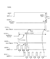
図5は、本発明に適応可能なMFP100の電源供給を停止するタイミングチャートを示す図である。
5001は、通信部4001によるホストPC200からのポーリングパケット検知のタイミングを示す。5002は、判定方法選択部4002による電源供給停止実行部4005に対する指示のタイミングを示す。5003は、電源供給停止実行部4005が判定方法選択部4002によって指示されている判定方法を示す。
FIG. 5 is a timing chart for stopping the power supply of the
5004は、通信状況判定部4003が一定時間内にポーリングパケットを受け取らなかった場合の電源供給停止実行部4005への通知のタイミングを示す。5005は、使用状況判定部4004による、MFP100がユーザに使われていない状態が一定時間続いた場合の電源供給停止実行部4005への通知のタイミングを示す。5006は、電源供給停止実行部4005による電源ユニット110への電源供給停止指示のタイミングを示す。5007は、電源ユニット110によるMFP100への電源供給、停止のタイミングを示す。
MFP100起動時のT100において、判定方法選択部4002は、電源供給停止実行部4005に対して、「使用状況判定部4004の通知で電源停止を実行する」ように指示する。
T101において、判定方法選択部4002は、ポーリングバケット受信を検知すると、電源供給停止実行部4005に対して、「通信状況判定部4003の通知で電源停止を実行する」ように指示する。
At T100 when the
In T101, when detecting the polling bucket reception, the determination
T102において、使用状況判定部4004は、MFP100がユーザに使われていない状態が一定時間続いたことを検知し、電源供給停止実行部4005に通知する。電源供給停止実行部4005は、上記T101で「通信状況判定部4003の通知で電源停止を実行する」ように指示されているため、使用状況判定部4004からの通知を無視する。
In T102, the use
T103において、通信状況判定部4003は、一定時間t1内にポーリングパケットを受け取らなかったことを検知し、電源供給停止実行部4005に通知する。電源供給停止実行部4005は、上記T101で「通信状況判定部4003の通知で電源停止を実行する」ように指示されているため、電源ユニット110へ電源停止を指示する。電源停止の指示を受けた電源ユニット110は、T104において、MFPの電源供給を停止する。
In T103, the communication
次に、MFP100が複数台のホストPCからポーリングパケットを検知した場合について説明する。
図6は、本発明に適応可能な複数台のホストPCからポーリングパケットを検知した場合のMFP100の電源供給を停止するタイミングチャートを示す図である。
6002は、通信部4001による1台目のホストPC(例えばホストPC200)からのポーリングパケット検知のタイミングを示す。6001、通信部4001による2台目のホストPC(例えばホストPC300)のポーリングパケット検知のタイミングを示す。6003は、判定方法選択部4002による電源供給停止実行部4005に対する指示のタイミングを示す。
6004は、電源供給停止実行部4005が判定方法選択部4002によって指示されている判定方法を示す。6005は、通信状況判定部4003が一定時間内にポーリングパケットを受け取らなかった場合の電源供給停止実行部4005への通知のタイミングを示す。6006は、電源供給停止実行部4005による電源ユニット110への電源供給停止指示のタイミングを示す。6007は、電源ユニット110によるMFP100への電源供給、停止のタイミングを示す。
Next, a case where
FIG. 6 is a timing chart for stopping the power supply of the
T200において、判定方法選択部4002は、ポーリングバケット受信を検知すると、電源供給停止実行部4005に対して、「通信状況判定部4003の通知で電源停止を実行する」ように指示する。
In T200, when detecting the polling bucket reception, the determination
T201において、判定方法選択部4002は2台目のホストPCからのポーリングパケットを検知するが、電源供給停止実行部4005への通知は、上記T200で通知済みであるためここでは通知は行わない。
In T201, the determination
T202において、通信状況判定部4003は、1台目のホストPCから一定時間t1内にポーリングパケットを受け取らなかったことを検知するが、2台目のホストPCから一定時間内にポーリングパケットを受け取っているため、電源供給停止実行部4005へ通知は行わない。
In T202, the communication
T203において、通信状況判定部4003は2台目のホストPCから一定時間t1内にポーリングパケットを受け取らなかったことを検知し、他のホストPCからもポーリングを受けていないことを確認し、電源供給停止実行部4005に通知する。
In T203, the communication
電源供給停止実行部4005は、上記T200で「通信状況判定部4003の通知で電源停止を実行する」ように指示されているため、電源ユニット110へ電源停止を指示する。電源停止の指示を受けた電源ユニット110は、T204において、MFPの電源供給を停止する。
The power supply
以下、図7を参照して、PC200、PC300の動作を説明する。
図7は、本発明を実施するPC200、PC300の動作の一例を示すフローチャートである。図7に示す各ステップは、CPU202がHDD204に記憶されている制御プログラムをRAM203にロードして実行することで実現される。この制御プログラムは、MFP100用ドライバをインストールすることによってHDD204に記憶される。専用の制御プログラムを用いることで、MFP100はネットワーク400に接続された多数のホストPCの中から、MFP100を使用するユーザのホストPCを対象にした制御が可能となる。
Hereinafter, operations of the
FIG. 7 is a flowchart showing an example of operations of the
まず、S101において、CPU202は、ポーリング設定があるか(MFP100へのポーリングを行う設定がなされているか)否かを確認する。ユーザは、任意のタイミングで、キーボード209やマウス210を用いてポーリング設定を行うことができ、ユーザにより行われたポーリング設定はHDD204に格納されるものとする。
First, in step S <b> 101, the
ポーリング設定がない(ポーリングを行わない設定)と判定した場合(S101でNo)、CPU202は、S101に処理を戻す。
一方、ポーリング設定がある(ポーリングを行う設定)と判定した場合(S101でYes)、CPU202は、S102へ処理を進める。
When it is determined that there is no polling setting (setting for not performing polling) (No in S101), the
On the other hand, if it is determined that there is a polling setting (a setting for performing polling) (Yes in S101), the
S102では、CPU202は、ネットワークI/F205を介してMFP100へポーリングパケットを送信し、S103へ処理を進める。
S103では、CPU202は、上記S102で送信したポーリングパケットの応答を待つ。
In S102, the
In S103, the
そして、一定時間内にプリンタから応答がなかったと判定した場合(S103でNo)、CPU202は、S101に処理を戻す。
一方、一定時間内にプリンタから応答があったと判定した場合(S103でYes)、CPU202は、S104に処理を進める。
S104では、CPU202は、MFP100へホストPC情報(図2)を送信し、S101へ処理を戻す。
If it is determined that there is no response from the printer within a certain time (No in S103), the
On the other hand, if it is determined that there is a response from the printer within a certain time (Yes in S103), the
In S104, the
以下、図8を参照して、MFP100の動作を説明する。
図8は、本発明を実施するMFP100のフローチャートの一例である。図8に示す各ステップは、CPU101がROM103に記憶されている制御プログラムをRAM102にロードして実行することで実現される。
Hereinafter, the operation of the
FIG. 8 is an example of a flowchart of the
MFP100が起動されると、S201において、CPU101は、一定時間経過により自動で電源をオフするモード(第1電源オフモード;以下、タイマ電源オフモードと略称する)を設定する。この設定は、ROM103のデータ領域内の電源オフモード格納領域に格納されるものとする。このステップは、判定方法選択部4002(CPU101が制御プログラムにより実現する機能)が、電源供給停止実行部4005(CPU101が制御プログラムにより実現する機能)に対して、「使用状況判定部4004の通知で電源停止を実行する」ように指示する機能に対応する。
When
次に、S202において、CPU101は、自動スリープタイマをスタートさせる。自動スリープタイマの設定は、操作部115に表示される図示しない自動スリープタイマ設定メニューからユーザが設定可能であり、例えば「30分」等が設定される。なお、自動スリープタイマの設定情報は、ROM103のデータ領域に記憶される。
Next, in S202, the
次に、S203において、CPU101は、ホストPCからポーリングがあるか確認する。このステップは、通信部4001(CPU101が制御プログラムにより実現する機能)が、ネットワークI/F109を介してホストPCから送信されるポーリングパケットを受信したかどうかで確認される。このポーリングは、ホストPC200、300が、図7のS102で送信したポーリングパケットに対応する。
Next, in S203, the
CPU101は、ポーリングがあったと判定した場合(S203でYes)、S204に処理を進める。
S204では、CPU101は、ホストPC200からのポーリングにより電源オフを制御するモード(第2電源オフモード;以下、ポーリング電源オフモードと略称する)を設定し、S205へ処理を進める。この設定は、ROM103のデータ領域内の電源オフモード格納領域に上書きされるものとする。このステップは、判定方法選択部4002が、電源供給停止実行部4005に対して、「通信状況判定部4003の通知で電源停止を実行する」ように指示する機能に対応する。
If the
In S204, the
S205では、CPU101は、ホストPC200から受け取ったホストPC情報を登録し、S207へ処理を進める。このホストPC情報は、ホストPC200、300が図7のS104で送信したホストPC情報に対応する。なお、既に登録済みのホストPCからホストPC情報を受け取った場合は、登録済みのホストPC情報を更新する。
In S205, the
一方、上記S203において、ポーリングがなかったと判定した場合(No)、CPU101は、S206に処理を進める。ポーリングがなかった場合とは、上記S205でホストPC情報を登録済みのホストPCから一定時間内にポーリングがなかった場合を示す。なお、図示しないが、ホストPC情報を登録済みのホストPCが存在しない場合は、CPU101は、そのままS207へ処理を進めるものとする。
On the other hand, if it is determined in S203 that there is no polling (No), the
S206では、CPU101は、上記S203でポーリングなしと判定したホストPCの登録済みのホストPC情報を削除し、S207へ処理を進める。
S207では、CPU101は、スリープ移行条件が整っているかを確認する。スリープ移行条件としては、上記S202でスタートした自動スリープタイマが満了した場合、操作部115を介してユーザからスリープ移行の指示があった場合などがある。
In S206, the
In S207, the
スリープ移行条件が整っていない(満たしていない)と判定した場合(S207でNo)、CPU101は、S208に処理を進める。
S208では、CPU101は、自動スリープタイマをリセットする要因があるか確認する。リセットする要因としては、操作部115を介してユーザから何らかの操作があった場合、ネットワークI/F109を介してホストPC200から画像印刷の指示があった場合などがある。
If it is determined that the sleep transition condition is not satisfied (not satisfied) (No in S207), the
In S208, the
自動スリープタイマをリセットする要因がなかったと判定した場合(S208でNo)、CPU101は、S203に処理を戻す。
一方、自動スリープタイマをリセットする要因があったと判定した場合(S208でYes)、CPU101は、S209に処理を進める。
S209で、CPU101は、自動スリープタイマをゼロに戻して再スタートさせ(リスタートさせ)、S203に処理を戻す。
If it is determined that there is no cause for resetting the automatic sleep timer (No in S208), the
On the other hand, if it is determined that there is a factor for resetting the automatic sleep timer (Yes in S208), the
In S209, the
一方、上記S207において、スリープ移行条件が整っている(満たした)と判定した場合(Yes)、CPU101は、S210に処理を進める。
S210で、CPU101は、スリープ処理を行う。スリープ処理は、CPU101が、電源ユニット110に対して非常夜電源111の停止を指示し、印刷部113、読取部114、操作部115の図示しないスリープ復帰のためのキー以外の電力供給を停止する。
On the other hand, if it is determined in S207 that the sleep transition condition is satisfied (satisfied) (Yes), the
In S210, the
次に、S211において、CPU101は、ポーリング電源オフモードが設定されているかどうかを確認する。
ポーリング電源オフモードが設定されていると判定した場合(S211でYes)、CPU101は、S223へ処理を進める。S223以降の処理は後述する。
一方、ポーリング電源オフモードが設定されていないと判定した場合(S211でNo)、CPU101は、S212へ処理を進める。
S212では、CPU101は、電源オフタイマをスタートさせる。
Next, in S211, the
If it is determined that the polling power-off mode is set (Yes in S211), the
On the other hand, when it is determined that the polling power-off mode is not set (No in S211), the
In S212, the
次に、S213において、CPU101は、ホストPC200からポーリングがあるか確認する。
ポーリングが無かったと判定した場合(S213でNo)、CPU101は、S214に処理を進める。
Next, in S213, the
If it is determined that there is no polling (No in S213), the
S214では、CPU101は、スリープ復帰要因があるかを確認する。スリープ復帰要因には、ユーザによって操作部115の図示しないスリープ復帰のためのキーを押された場合、ネットワークI/F109を介してホストPC200から画像印刷の指示があった場合などがある。
In S214, the
スリープ復帰要因がなかったと判定した場合(S214でNo)、CPU101は、S215へ処理を進める。
S215では、CPU101は、電源オフタイマが満了したかどうかを判定する。電源オフタイマの設定は、任意のタイミングで操作部115の図示しない電源オフタイマ設定メニューからユーザが設定可能であり、この設定はROM103のデータ領域に格納されるものとする。
If it is determined that there is no cause for sleep recovery (No in S214), the
In S215, the
電源オフタイマが満了していないと判定した場合(S215でNo)、CPU101は、S213に処理を戻す。
一方、電源オフタイマが満了したと判定した場合(S215でYes)、CPU101は、S216に処理を進める。上記S214,S215のステップは、使用状況判定部4004が、使用状況を判定する機能に対応する。
If it is determined that the power-off timer has not expired (No in S215), the
On the other hand, when it is determined that the power-off timer has expired (Yes in S215), the
S216では、CPU101は、電源ユニット110に対して常夜電源112の停止を指示し、MFP100全体の電力供給を停止する(電源オフ実行)。上記S215→S216のステップは、使用状況判定部4004が電源供給停止実行部4005に通知を行い、この通知で電源供給停止実行部4005が電源停止を実行する機能に対応する。これにより、フローチャートの処理が終了する。
In step S <b> 216, the
また、上記S214において、スリープ復帰要因があったと判定した場合(S214でYes)、CPU101は、S217へ処理を進める。
S217では、CPU101は、電源オフタイマをゼロに戻し停止させ(電源オフタイマストップ)、S218に処理を進める。
If it is determined in S214 that there is a cause for returning from sleep (Yes in S214), the
In S217, the
S218では、CPU101は、スリープ復帰処理を実行し、S219に処理を進める。スリープ復帰処理では、CPU101が電源ユニット110に対して非常夜電源111の復帰を指示し、印刷部113、読取部114、操作部115の電力供給を再開させる。
S219では、CPU101は、自動スリープタイマをゼロに戻し再スタートさせ(自動スリープタイマリスタート)、S203に処理を戻す。
In S218, the
In S219, the
また、上記S213において、ポーリングがあったと判定した場合(Yes)、CPU101は、S220に処理を進める。
S220では、CPU101は、ポーリング電源オフモードを設定し、S221に処理を進める。
S221では、CPU101は、ホストPCから受け取ったホストPC情報を登録し、S222に処理を進める。既に登録済みのホストPCからホストPC情報を受け取った場合は、登録済みのホストPC情報を更新する。
If it is determined in S213 that there is polling (Yes), the
In S220, the
In S221, the
S222では、CPU101は、電源オフタイマをゼロに戻し停止させ(電源オフタイマストップ)、S223に処理を進める。
S223では、CPU101は、スリープ復帰要因があるかを確認する。
スリープ復帰要因があったと判定した場合(S223でYes)、CPU101は、S218に処理を進める。
一方、スリープ復帰要因がなかったと判定した場合(S223でNo)、CPU101は、S224に処理を進める。
In S222, the
In S223, the
If it is determined that there is a cause for returning from sleep (Yes in S223), the
On the other hand, if it is determined that there is no sleep return factor (No in S223), the
S224では、CPU101は、ホストPCからポーリングがあるか確認する。ポーリングがあったと判定した場合(S224でYes)、CPU101は、S227に処理を進める。
In S224, the
S227では、CPU101は、ホストPCから受け取ったホストPC情報を登録し、S223に処理を戻す。既に登録済みのホストPCからホストPC情報を受け取った場合は、登録済みのホストPC情報を更新する。
In S227, the
一方、上記S224において、ポーリングがなかったと判定した場合(No)、CPU101は、S225に処理を進める。
S225では、CPU101は、上記S224でポーリングなしと判定したホストPCの登録済みのホストPC情報を削除し、S226に処理を進める。
On the other hand, if it is determined in S224 that there is no polling (No), the
In S225, the
S226では、CPU101は、ホストPC情報があるかを確認する。上記S224〜S226のステップは、通信状況判定部4003が、通信状況を判定する機能に対応する。
In S226, the
ホストPC情報があると判定した場合(S226でYes)、CPU101は、S223に処理を戻す。
一方、ホストPC情報がないと判定した場合(S226でNo)、CPU101は、S216に処理を進め、電源ユニット110に対して常夜電源112の停止を指示し、MFP100全体の電力供給を停止する(電源オフ実行)。上記S226→S216のステップは、通信状況判定部4003が電源供給停止実行部4005に通知を行い、この通知で電源供給停止実行部4005が電源停止を実行する機能に対応する。これにより、フローチャートの処理が終了する。
If it is determined that there is host PC information (Yes in S226), the
On the other hand, if it is determined that there is no host PC information (No in S226), the
なお、本実施例では、電源オフを実行するのは、MFP100がスリープ移行した後にホストPC200や300からポーリングがなくなった場合としている。しかし、スリープ移行していない場合でも、ポーリングがなくなったタイミングで電源オフを実行する構成にしても本発明は適応可能である。
In this embodiment, the power-off is executed when polling from the
なお、上述の説明ではスリープ時でもCPU101が動作する構成であったが、スリープ時にCPU101を停止するように構成してもよい。この構成の場合、スリープ時において、ネットワークI/F109は、ホストPCからのポーリングを受けるまではタイマ電源オフモードで動作し、ホストPCからのポーリングパケットの受信や他のスリープ復帰要因がないと一定時間経過にMFP100の電源オフを実行する。なお、ネットワークI/F109は、ホストPCからのポーリングパケットの受信や他のスリープ復帰要因を検知すると、CPU101を起動させ、CPU101に制御を移すものとする。このような構成により、MFP100は、PCからポーリングを受けるまでの間はCPUを停止した状態で待機することができ、電源オフ実行するまでの消費電力をより抑えることができる。
In the above description, the
また、本実施例では、MFP100が図8のS203、S213、S224で受信判断するポーリングパケットを、MFP100のスキャンドライバがインストールされているホストPCから定期的に送信されるポーリングパケットのみとしている。よって、このポーリングパケットの受信を判定することにより、FP100のスキャンドライバがインストールされているホストPC、即ちMFP100を使用される可能性があるホストコンピュータが起動しているかどうかを高確率で判定することができる。
In this embodiment, the polling packet that the
また、本実施例では、本発明の情報処理装置の一例として画像形成装置を説明したが、画像形成装置以外の画像形成装置であっても本発明を適用可能である。この場合、ポーリングパケットは、本発明の情報処理装置を使用するためのプログラムがインストールされたホストPCから前記プログラムにより送信されるポーリングパケットとする。 In this embodiment, the image forming apparatus is described as an example of the information processing apparatus of the present invention. However, the present invention can be applied to an image forming apparatus other than the image forming apparatus. In this case, the polling packet is a polling packet transmitted by the program from the host PC in which the program for using the information processing apparatus of the present invention is installed.
また、MFP100のスキャンドライバのポーリングパケットの代わりに他のプログラムから送信されるポーリングパケットを用いてもよい。例えば、MFP100のスキャンドライバではないMFP100を使用するための他のプログラムをホストPCにインストールしておき、該プログラムによりMFPに出力されるポーリングパケットを、MFP100が図8のS203、S213、S224で受信判断するように構成してもよい。即ち、ホストPCにインストールされるMFP100を使用するためのプログラムで、MFP100に定期的にポーリングパケットを送信するプログラムであれば、他のプログラムであっても本発明に適用可能である。
Further, a polling packet transmitted from another program may be used instead of the polling packet of the scan driver of
以上示したように、本実施例によれば、装置起動後、ホストコンピュータと接続がない場合は、一定時間経過により自動で電源をオフするモード(タイマ電源オフモード)で動作するので、装置起動後に即座に電源がオフされたりすることを回避できる。また、装置起動後、ホストコンピュータと接続された場合は、ホストコンピュータから使用される可能性があるか否かを判定し電源をオフするモード(ポーリング電源オフモード)に切り替えるので、ホストコンピュータから使用するときに装置の電源がオフされているという事態の発生を回避できる。さらに、使用される可能性があるか否かを判定する対象のホストコンピュータを、装置を使用するユーザのものに限定することで、装置の前でユーザが操作しているときに強制的に電源がオフされる問題が発生する確率を低減させることができる。 As described above, according to the present embodiment, after the apparatus is started, when there is no connection with the host computer, it operates in a mode in which the power is automatically turned off after a predetermined time (timer power-off mode). It can be avoided that the power is immediately turned off later. In addition, when connected to a host computer after the device is started, it is determined whether there is a possibility of being used from the host computer, and the mode is switched to the power-off mode (polling power-off mode). It is possible to avoid the occurrence of a situation where the power of the device is turned off. Furthermore, by limiting the target host computer to determine whether there is a possibility of being used or not to the user who uses the device, it is possible to force the power supply when the user is operating in front of the device. It is possible to reduce the probability of occurrence of a problem of turning off.
このように、一定時間の経過により自動で装置の電源をオフするモード(タイマ電源オフモード)と、ネットワーク上のホストコンピュータから使用される可能性がないことを判定して電源をオフするモード(ポーリング電源オフモード)を適切に切り替える制御を行うことにより、従来の問題点を解決することができる。 In this way, a mode in which the power of the apparatus is automatically turned off after a lapse of a certain time (timer power off mode) and a mode in which the power is turned off by determining that there is no possibility of being used from a host computer on the network ( The conventional problem can be solved by appropriately controlling the switching of the polling power-off mode.
なお、ポーリング電源オフモードへの切替は、ポーリングを受けているホストPCの中から特定のホストPCを設定し、該特定のホストPCに対して図5のような制御を行う構成としても本発明は適応可能である。即ち、MFP100のCPU101は、特定のホストPCからのポーリングバケット受信を検知すると、ポーリング電源オフモードへ切り替える。そして、CPU101は、上記特定のホストPCから一定時間内にポーリングパケットを受け取らなかったことを検知すると、電源オフ実行するように構成してもよい。
Note that the switching to the polling power-off mode can be achieved by configuring a specific host PC from among the host PCs that are being polled and performing control as shown in FIG. 5 for the specific host PC. Is adaptable. That is, when
なお、上記特定のPCを設定する方法には、図示しないホストPC設定部によって、ジョブを実行したことがあるホストPC、操作部115からユーザによって選択されたホストPC、上述したショートカットキー登録されているホストPC、何らかの状態変化通知があったホストPCなどに設定する方法がある。なお、上記ホストPC設定部は、CPU101が制御プログラムを実行することで実現される機能である。また、上記何らかの状態変化通知があったホストPCとは、通知されるホストPC情報に何らかの変化があったホストPCを示す。即ち、通知されるホストPC情報2000内のPC名2001、IPアドレス2002、カスタムスキャン設定1(20003)、カスタムスキャン設定2(20004)のいずれかに変化があったホストPCを示す。
The specific PC setting method includes a host PC that has executed a job by a host PC setting unit (not shown), a host PC selected by the user from the
なお、図5、図6に示した例では、ホストPCからのポーリングが続いているかぎり、MFP100は電源供給停止が実行されないこととなるが、このような場合でもMFP100が電源オフ実行され得る構成としてもよい。
In the example shown in FIGS. 5 and 6, as long as polling from the host PC continues, the power supply to the
例えば、ホストPCからのポーリングが一定時間続いた場合、MFP100のCPU101は、ポーリングしている各ホストPCに対して、電源オフ実行の可否を問い合わせる。そして、全てのホストPCからシャットダウンの許可を受信した場合に、CPU101は、電源オフ実行する。なお、ホストPC側では、例えば、ホストPC200にインストールされているMFP100のスキャンドライバが、上記MFP100からのシャットダウンの可否の問い合わせを受信すると、電源オフ実行の可否を選択するための画面を表示して、ユーザに電源オフ実行の可否の選択を促す。そして、ユーザによる電源オフ実行の可否の選択を受けると、ホストPC上で動作する上記スキャンドライバは、上記ユーザによる選択結果をMFP100に送信するものとする。このような構成により、MFP100が自身で電源オフ可能と判断できない状況でも、ユーザに許可を得ることで電源オフ実行することができるようになる。
For example, when polling from the host PC continues for a certain period of time, the
また、特定のホストPCを選択するための設定に基づいて、電源オフ実行の基準を変更するようにしてもよい。特定のホストPCを選択するための設定には、例えば、以下の(1)〜(3)のようなものがある。 Further, the power-off execution reference may be changed based on the setting for selecting a specific host PC. Examples of settings for selecting a specific host PC include the following (1) to (3).
(1)スキャンドライバを利用してMFP100へジョブ投入したホストPCを特定のホストPCに選択する設定。
(2)ショートカットキー登録されているホストPCを特定のホストPCに選択する設定。
(3)状態変化通知があったホストPCを特定のホストPCに選択する設定。
例えば、上記(1)の設定の場合、スキャンドライバを利用してMFP100へジョブ投入したホストPCがあった場合、CPU101は、該ホストPCに対して電源オフ実行の可否を問い合わせて電源オフ実行する、又は、即座に電源オフ実行する。
(1) Setting for selecting a host PC that has submitted a job to
(2) Setting for selecting a host PC registered as a shortcut key as a specific host PC.
(3) Setting for selecting a host PC that has been notified of a state change as a specific host PC.
For example, in the case of setting (1) above, when there is a host PC that has submitted a job to the
また、上記(2)の設定の場合、ショートカットキー登録されているPCからポーリングがあった場合に、CPU101はポーリング電源オフモードに切り替える。そして、該ショートカットキー登録されているホストPCからポーリングがなくなった場合、CPU101は、該ショートカットキー登録されているホストPCに対して電源オフ実行の可否を問い合わせて電源オフ実行する、又は、即座に電源オフ実行する。
In the case of setting (2) above, when polling is performed from the PC registered with the shortcut key, the
また、上記(3)の設定の場合、状態変化通知があったホストPCからポーリングがなくなった場合、CPU101は、該状態変化通知があったホストPCに対して電源オフ実行の可否を問い合わせて電源オフ実行する、又は、即座に電源オフ実行する。
In the case of setting (3) above, when polling is stopped from the host PC that has received the state change notification, the
また、CPU101は、ポーリング電源オフモードに切り替えるタイミングを、図6のT201のような複数台のホストPCからのポーリングを検知したタイミングに変更しても、本発明は適応可能である。
Further, the present invention can be applied even when the
例えば、ポーリングするホストPCが所定台数(管理者により予め設定可能)を超えた場合に、CPU101がポーリング電源オフモードに切り替えるように構成してもよい。
また、ポーリングするホストPCが所定台数(管理者により予め設定可能)以下になった場合に、CPU101が、電源オフ実行の可否をポーリングしているホストPCに問い合わせて電源オフ実行する、又は、即座に電源オフ実行するように構成してもよい。
For example, the
In addition, when the number of host PCs to be polled falls below a predetermined number (which can be set in advance by the administrator), the
さらに、MFP100に対してホストPC情報を登録可能なホストPCの台数の上限を所定台数(例えば10台)とし、上記所定台数を登録した状態で新たなホストPCからポーリングがあっても、該ポーリングを無視するように構成してもよい。
Further, the upper limit of the number of host PCs that can register host PC information in the
そして、上記所定台数を登録した状態でポーリングが一定時間続いた場合、CPU101は上記所定台数のホストPCに対して、電源オフ実行の可否の問い合わせを行う。そして、問い合わせた全ホストPCから電源オフ実行の許可を受信し、さらに新たなホストPC(所定台数+1台目のホストPC)からポーリングがあった場合、CPU101は、前記新たなホストPCに対して電源オフ実行の可否の問い合わせを行う。そして、前記新たなホストPCから電源オフ実行の許可を受信した場合には、CPU101は電源オフ実行する。一方、前記新たなホストPCからシャットダウンの許可しない旨の返信を受信した場合には、CPU101は、上記所定台数のホストPCの登録を全て削除し、上記新たなホストPCのホストPC情報を登録するものとする。
When polling continues for a predetermined time with the predetermined number registered, the
以上示したように、本発明のMFPは、従来のMFPように自身からPCに対して状態
を問い合わせるものではなく、PCからのポーリングを監視するものである。このため、本発明のMFPでは、監視するPCを限定し必要最低限に抑えることができる(監視対象が不特定多数ではない)。また、PCからのポーリングを監視するまでは、監視無しに待機することができ、本発明のMFPではPC監視の処理で使用する電力を従来より抑えることができる。
As described above, the MFP of the present invention does not inquire about the status from the PC itself, unlike the conventional MFP, but monitors polling from the PC. Therefore, in the MFP of the present invention, the number of PCs to be monitored can be limited to the minimum necessary (the monitoring target is not an unspecified number). Moreover, until the monitor polling from PC may be waiting without monitoring, the electric power used in the processing of MFP the PC monitor of the present invention can be suppressed compared with the conventional.
なお、上述した各種データの構成及びその内容はこれに限定されるものではなく、用途や目的に応じて、様々な構成や内容で構成されることは言うまでもない。
以上、一実施形態について示したが、本発明は、例えば、システム、装置、方法、プログラムもしくは記憶媒体等としての実施態様をとることが可能である。具体的には、複数の機器から構成されるシステムに適用しても良いし、また、一つの機器からなる装置に適用しても良い。
It should be noted that the configuration and contents of the various data described above are not limited to this, and it goes without saying that the various data and configurations are configured according to the application and purpose.
Although one embodiment has been described above, the present invention can take an embodiment as, for example, a system, apparatus, method, program, or storage medium. Specifically, the present invention may be applied to a system composed of a plurality of devices, or may be applied to an apparatus composed of a single device.
また、上記各実施例を組み合わせた構成も全て本発明に含まれるものである。
また、以上の実施例では、画像形成装置の電源制御について説明したが、画像形成装置以外の電子機器の電源制御にも本発明は適用可能である。
Moreover, all the structures which combined said each Example are also contained in this invention.
In the above embodiments, the power control of the image forming apparatus has been described. However, the present invention can also be applied to power control of electronic equipment other than the image forming apparatus.
(他の実施例)
また、本発明は、以下の処理を実行することによっても実現される。即ち、上述した実施形態の機能を実現するソフトウェア(プログラム)を、ネットワーク又は各種記憶媒体を介してシステム或いは装置に供給し、そのシステム或いは装置のコンピュータ(またはCPUやMPU等)がプログラムを読み出して実行する処理である。
(Other examples)
The present invention can also be realized by executing the following processing. That is, software (program) that realizes the functions of the above-described embodiments is supplied to a system or apparatus via a network or various storage media, and a computer (or CPU, MPU, or the like) of the system or apparatus reads the program. It is a process to be executed.
また、本発明は、複数の機器から構成されるシステムに適用しても、1つの機器からなる装置に適用してもよい。
本発明は上記実施例に限定されるものではなく、本発明の趣旨に基づき種々の変形(各実施例の有機的な組合せを含む)が可能であり、それらを本発明の範囲から除外するものではない。即ち、上述した各実施例及びその変形例を組み合わせた構成も全て本発明に含まれるものである。
Further, the present invention may be applied to a system composed of a plurality of devices or an apparatus composed of a single device.
The present invention is not limited to the above embodiments, and various modifications (including organic combinations of the embodiments) are possible based on the spirit of the present invention, and these are excluded from the scope of the present invention. is not. That is, the present invention includes all the combinations of the above-described embodiments and modifications thereof.
100 画像形成装置(MFP)
200,300 ホストコンピュータ(PC)
400 ネットワーク
100 Image forming apparatus (MFP)
200,300 Host computer (PC)
400 network
Claims (12)
前記画像形成装置と定期的な通信を行う情報処理装置を登録する登録手段と、
前記画像形成装置と前記定期的な通信を行う情報処理装置が登録されていない場合には、前記画像形成装置の使用状況に基づいて前記画像形成装置の電源をオフする第1電源オフモードを選択し、前記画像形成装置と前記定期的な通信を行う情報処理装置が登録されている場合には、前記登録手段に登録されている前記情報処理装置と前記定期的な通信が検知されなくなったことに基づいて前記画像形成装置の電源をオフする第2電源オフモードを選択する選択手段と、
前記選択手段により選択された電源オフモードに基づいて、前記画像形成装置の電源をオフするように制御する制御手段と、
を有することを特徴とする画像形成装置。 An image forming apparatus capable of communicating with one or more information processing apparatuses,
Registration means for registering an information processing apparatus that performs periodic communication with the image forming apparatus ;
When the information processing apparatus for performing the periodic communication with the image forming apparatus is not registered, selecting a first power off mode for turning off the power supply of the image forming apparatus based on the usage of the image forming apparatus When the information processing apparatus that performs the periodic communication with the image forming apparatus is registered , the periodic communication with the information processing apparatus registered in the registration unit is not detected. Selection means for selecting a second power-off mode for turning off the power of the image forming apparatus based on
Control means for controlling the power of the image forming apparatus to be turned off based on the power-off mode selected by the selection means;
An image forming apparatus comprising:
前記画像形成装置と定期的な通信を行う情報処理装置を登録する登録ステップと、
前記画像形成装置と前記定期的な通信を行う情報処理装置が登録されていない場合には、前記画像形成装置の使用状況に基づいて前記画像形成装置の電源をオフする第1電源オフモードを選択し、前記画像形成装置と前記定期的な通信を行う情報処理装置が登録されている場合には、前記登録ステップで登録されている前記情報処理装置と前記定期的な通信が検知されなくなったことに基づいて前記画像形成装置の電源をオフする第2電源オフモードを選択する選択ステップと、
前記選択ステップにより選択された電源オフモードに基づいて、前記画像形成装置の電源をオフするように制御する制御ステップと、
を有することを特徴とする画像形成装置の制御方法。 An image forming apparatus control method capable of communicating with one or a plurality of information processing apparatuses,
A registration step of registering an information processing apparatus that performs periodic communication with the image forming apparatus ;
When the information processing apparatus for performing the periodic communication with the image forming apparatus has not been registered, selecting a first power off mode for turning off the power of the image forming apparatus based on the usage of the image forming apparatus When the information processing apparatus that performs the periodic communication with the image forming apparatus is registered , the periodic communication with the information processing apparatus registered in the registration step is not detected. Selecting a second power-off mode for turning off the power of the image forming apparatus based on
A control step for controlling to turn off the power of the image forming apparatus based on the power-off mode selected in the selection step;
A control method for an image forming apparatus, comprising:
Priority Applications (3)
| Application Number | Priority Date | Filing Date | Title |
|---|---|---|---|
| JP2012090677A JP6016425B2 (en) | 2012-04-12 | 2012-04-12 | Image forming apparatus, image forming apparatus control method, and program |
| CN2013101276372A CN103379240A (en) | 2012-04-12 | 2013-04-10 | Image forming apparatus, method for controlling image forming apparatus, and a system |
| US13/860,368 US20130275793A1 (en) | 2012-04-12 | 2013-04-10 | Image forming apparatus, method for controlling image forming apparatus, and a system |
Applications Claiming Priority (1)
| Application Number | Priority Date | Filing Date | Title |
|---|---|---|---|
| JP2012090677A JP6016425B2 (en) | 2012-04-12 | 2012-04-12 | Image forming apparatus, image forming apparatus control method, and program |
Publications (3)
| Publication Number | Publication Date |
|---|---|
| JP2013216061A JP2013216061A (en) | 2013-10-24 |
| JP2013216061A5 JP2013216061A5 (en) | 2015-05-28 |
| JP6016425B2 true JP6016425B2 (en) | 2016-10-26 |
Family
ID=49326179
Family Applications (1)
| Application Number | Title | Priority Date | Filing Date |
|---|---|---|---|
| JP2012090677A Active JP6016425B2 (en) | 2012-04-12 | 2012-04-12 | Image forming apparatus, image forming apparatus control method, and program |
Country Status (3)
| Country | Link |
|---|---|
| US (1) | US20130275793A1 (en) |
| JP (1) | JP6016425B2 (en) |
| CN (1) | CN103379240A (en) |
Families Citing this family (6)
| Publication number | Priority date | Publication date | Assignee | Title |
|---|---|---|---|---|
| JP6178713B2 (en) * | 2013-12-13 | 2017-08-09 | 株式会社沖データ | Image forming apparatus |
| US9509872B2 (en) * | 2014-09-05 | 2016-11-29 | Brother Kogyo Kabushiki Kaisha | Image reading apparatus and non-transitory computer-readable medium having image reading program |
| US10310592B2 (en) | 2015-11-02 | 2019-06-04 | Ricoh Company, Ltd. | Device, operation-mode control method, and recording medium |
| US11056237B2 (en) * | 2016-06-08 | 2021-07-06 | Health Value Analytics, Inc. | System and method for determining and indicating value of healthcare |
| US10045297B1 (en) * | 2017-01-24 | 2018-08-07 | Google Llc | Increased time in a suspended state during network transmissions |
| US10671143B2 (en) * | 2018-01-11 | 2020-06-02 | Red Hat Israel, Ltd. | Power management using automation engine |
Family Cites Families (13)
| Publication number | Priority date | Publication date | Assignee | Title |
|---|---|---|---|---|
| JP3056793B2 (en) * | 1990-12-21 | 2000-06-26 | 株式会社リコー | Office equipment on / off control device |
| KR0167615B1 (en) * | 1993-12-09 | 1999-01-15 | 미따라이 하지메 | Printing apparatus, system having the same and method of controlling the printing apparatus |
| JPH09191568A (en) * | 1996-01-11 | 1997-07-22 | Canon Inc | Output device and power supply control thereof |
| KR100245199B1 (en) * | 1996-05-21 | 2000-02-15 | 윤종용 | Method of converting power saving mode in a computer |
| JP4217445B2 (en) * | 2002-09-06 | 2009-02-04 | キヤノン株式会社 | Data processing apparatus, power control method, computer-readable storage medium, and program |
| JP2005066894A (en) * | 2003-08-20 | 2005-03-17 | Fuji Xerox Co Ltd | Image forming apparatus and power-saving control method therefor |
| JP2006168175A (en) * | 2004-12-15 | 2006-06-29 | Canon Inc | Method for controlling printing device, program and storage medium which can be read by computer |
| TWI324865B (en) * | 2006-03-31 | 2010-05-11 | Hon Hai Prec Ind Co Ltd | Power management system and method for network device |
| US8204611B2 (en) * | 2007-02-20 | 2012-06-19 | Caterpillar Inc. | Method for reducing quiescent power draw and machine using same |
| JP4550091B2 (en) * | 2007-08-21 | 2010-09-22 | 株式会社沖データ | Image processing device |
| JP2010198486A (en) * | 2009-02-26 | 2010-09-09 | Canon Inc | Network apparatus and method for controlling network apparatus, and program |
| CA2770469A1 (en) * | 2009-08-20 | 2011-02-24 | E. I. Du Pont De Nemours And Company | Process for producing shaped articles of poly(trimethylene arylate)/polystyrene |
| JP5244157B2 (en) * | 2010-07-09 | 2013-07-24 | シャープ株式会社 | Image processing apparatus, power saving mode transition control method, computer-readable recording medium, and computer program |
-
2012
- 2012-04-12 JP JP2012090677A patent/JP6016425B2/en active Active
-
2013
- 2013-04-10 CN CN2013101276372A patent/CN103379240A/en active Pending
- 2013-04-10 US US13/860,368 patent/US20130275793A1/en not_active Abandoned
Also Published As
| Publication number | Publication date |
|---|---|
| JP2013216061A (en) | 2013-10-24 |
| US20130275793A1 (en) | 2013-10-17 |
| CN103379240A (en) | 2013-10-30 |
Similar Documents
| Publication | Publication Date | Title |
|---|---|---|
| JP6016425B2 (en) | Image forming apparatus, image forming apparatus control method, and program | |
| US8521913B2 (en) | Information processing device, information processing system provided with the same, and computer readable medium for the same | |
| JP2013034072A (en) | Image processing device, control method for image processing device, and control program for image processing device | |
| JP2013222394A (en) | Information processing apparatus, control method therefor, and program | |
| JP2017177573A (en) | Information processing device provided with pci (peripheral component interconnect) device with connecting to pci bus and method for controlling information processing device | |
| JP5395578B2 (en) | Image forming system, image forming apparatus, screen display method, control method, and program | |
| JP2015170959A (en) | Image processing apparatus, control method of image processing apparatus, and program | |
| US20140146345A1 (en) | Information processing apparatus, information processing apparatus control method, and storage medium | |
| JP2017209869A (en) | Information processing apparatus that determines level of electric power saving of processor according to return time reported from device connected to processor and electric power saving method for processor | |
| US20120154859A1 (en) | Image processing apparatus, server apparatus, control method thereof, and storage medium therefor | |
| US20100332879A1 (en) | Image forming apparatus | |
| US9479663B2 (en) | Information processing apparatus, method for controlling information processing apparatus, and storage medium | |
| JP2006092481A (en) | Information processing apparatus | |
| JP5818447B2 (en) | Image processing apparatus, image processing apparatus control method, and program | |
| JP5651956B2 (en) | Power control method, power control apparatus, and power control program | |
| JP2015005954A (en) | Information processing device, method for controlling information processing device, and program | |
| JP6702790B2 (en) | Information processing apparatus having network interface having proxy response function | |
| JP6366271B2 (en) | Information processing apparatus and control method of information processing apparatus | |
| JP6798351B2 (en) | Multifunction devices, information display methods, and computer programs | |
| JP2015112818A (en) | Image forming apparatus, control method, and program | |
| JP2006095741A (en) | Information processing equipment | |
| JP2011194749A (en) | Image forming device | |
| JP5234430B2 (en) | Managed apparatus, management program, and management method | |
| US20180249023A1 (en) | Information Processing Apparatus and Recording Medium | |
| JP2008268326A (en) | Image forming apparatus and power control method |
Legal Events
| Date | Code | Title | Description |
|---|---|---|---|
| A521 | Request for written amendment filed |
Free format text: JAPANESE INTERMEDIATE CODE: A523 Effective date: 20150409 |
|
| A621 | Written request for application examination |
Free format text: JAPANESE INTERMEDIATE CODE: A621 Effective date: 20150409 |
|
| RD03 | Notification of appointment of power of attorney |
Free format text: JAPANESE INTERMEDIATE CODE: A7423 Effective date: 20150409 |
|
| A977 | Report on retrieval |
Free format text: JAPANESE INTERMEDIATE CODE: A971007 Effective date: 20160212 |
|
| A131 | Notification of reasons for refusal |
Free format text: JAPANESE INTERMEDIATE CODE: A131 Effective date: 20160216 |
|
| A521 | Request for written amendment filed |
Free format text: JAPANESE INTERMEDIATE CODE: A523 Effective date: 20160413 |
|
| TRDD | Decision of grant or rejection written | ||
| A01 | Written decision to grant a patent or to grant a registration (utility model) |
Free format text: JAPANESE INTERMEDIATE CODE: A01 Effective date: 20160830 |
|
| A61 | First payment of annual fees (during grant procedure) |
Free format text: JAPANESE INTERMEDIATE CODE: A61 Effective date: 20160927 |
|
| R151 | Written notification of patent or utility model registration |
Ref document number: 6016425 Country of ref document: JP Free format text: JAPANESE INTERMEDIATE CODE: R151 |