JP6004738B2 - Imprint apparatus and article manufacturing method using the same - Google Patents
Imprint apparatus and article manufacturing method using the same Download PDFInfo
- Publication number
- JP6004738B2 JP6004738B2 JP2012111419A JP2012111419A JP6004738B2 JP 6004738 B2 JP6004738 B2 JP 6004738B2 JP 2012111419 A JP2012111419 A JP 2012111419A JP 2012111419 A JP2012111419 A JP 2012111419A JP 6004738 B2 JP6004738 B2 JP 6004738B2
- Authority
- JP
- Japan
- Prior art keywords
- mold
- resin
- substrate
- contact
- holding
- Prior art date
- Legal status (The legal status is an assumption and is not a legal conclusion. Google has not performed a legal analysis and makes no representation as to the accuracy of the status listed.)
- Active
Links
Images


Classifications
-
- G—PHYSICS
- G03—PHOTOGRAPHY; CINEMATOGRAPHY; ANALOGOUS TECHNIQUES USING WAVES OTHER THAN OPTICAL WAVES; ELECTROGRAPHY; HOLOGRAPHY
- G03F—PHOTOMECHANICAL PRODUCTION OF TEXTURED OR PATTERNED SURFACES, e.g. FOR PRINTING, FOR PROCESSING OF SEMICONDUCTOR DEVICES; MATERIALS THEREFOR; ORIGINALS THEREFOR; APPARATUS SPECIALLY ADAPTED THEREFOR
- G03F7/00—Photomechanical, e.g. photolithographic, production of textured or patterned surfaces, e.g. printing surfaces; Materials therefor, e.g. comprising photoresists; Apparatus specially adapted therefor
- G03F7/70—Microphotolithographic exposure; Apparatus therefor
-
- G—PHYSICS
- G03—PHOTOGRAPHY; CINEMATOGRAPHY; ANALOGOUS TECHNIQUES USING WAVES OTHER THAN OPTICAL WAVES; ELECTROGRAPHY; HOLOGRAPHY
- G03F—PHOTOMECHANICAL PRODUCTION OF TEXTURED OR PATTERNED SURFACES, e.g. FOR PRINTING, FOR PROCESSING OF SEMICONDUCTOR DEVICES; MATERIALS THEREFOR; ORIGINALS THEREFOR; APPARATUS SPECIALLY ADAPTED THEREFOR
- G03F7/00—Photomechanical, e.g. photolithographic, production of textured or patterned surfaces, e.g. printing surfaces; Materials therefor, e.g. comprising photoresists; Apparatus specially adapted therefor
- G03F7/0002—Lithographic processes using patterning methods other than those involving the exposure to radiation, e.g. by stamping
-
- B—PERFORMING OPERATIONS; TRANSPORTING
- B29—WORKING OF PLASTICS; WORKING OF SUBSTANCES IN A PLASTIC STATE IN GENERAL
- B29C—SHAPING OR JOINING OF PLASTICS; SHAPING OF MATERIAL IN A PLASTIC STATE, NOT OTHERWISE PROVIDED FOR; AFTER-TREATMENT OF THE SHAPED PRODUCTS, e.g. REPAIRING
- B29C59/00—Surface shaping of articles, e.g. embossing; Apparatus therefor
- B29C59/002—Component parts, details or accessories; Auxiliary operations
-
- B—PERFORMING OPERATIONS; TRANSPORTING
- B29—WORKING OF PLASTICS; WORKING OF SUBSTANCES IN A PLASTIC STATE IN GENERAL
- B29C—SHAPING OR JOINING OF PLASTICS; SHAPING OF MATERIAL IN A PLASTIC STATE, NOT OTHERWISE PROVIDED FOR; AFTER-TREATMENT OF THE SHAPED PRODUCTS, e.g. REPAIRING
- B29C59/00—Surface shaping of articles, e.g. embossing; Apparatus therefor
- B29C59/02—Surface shaping of articles, e.g. embossing; Apparatus therefor by mechanical means, e.g. pressing
- B29C59/022—Surface shaping of articles, e.g. embossing; Apparatus therefor by mechanical means, e.g. pressing characterised by the disposition or the configuration, e.g. dimensions, of the embossments or the shaping tools therefor
-
- B—PERFORMING OPERATIONS; TRANSPORTING
- B82—NANOTECHNOLOGY
- B82Y—SPECIFIC USES OR APPLICATIONS OF NANOSTRUCTURES; MEASUREMENT OR ANALYSIS OF NANOSTRUCTURES; MANUFACTURE OR TREATMENT OF NANOSTRUCTURES
- B82Y10/00—Nanotechnology for information processing, storage or transmission, e.g. quantum computing or single electron logic
-
- B—PERFORMING OPERATIONS; TRANSPORTING
- B82—NANOTECHNOLOGY
- B82Y—SPECIFIC USES OR APPLICATIONS OF NANOSTRUCTURES; MEASUREMENT OR ANALYSIS OF NANOSTRUCTURES; MANUFACTURE OR TREATMENT OF NANOSTRUCTURES
- B82Y40/00—Manufacture or treatment of nanostructures
-
- B—PERFORMING OPERATIONS; TRANSPORTING
- B29—WORKING OF PLASTICS; WORKING OF SUBSTANCES IN A PLASTIC STATE IN GENERAL
- B29C—SHAPING OR JOINING OF PLASTICS; SHAPING OF MATERIAL IN A PLASTIC STATE, NOT OTHERWISE PROVIDED FOR; AFTER-TREATMENT OF THE SHAPED PRODUCTS, e.g. REPAIRING
- B29C59/00—Surface shaping of articles, e.g. embossing; Apparatus therefor
- B29C59/02—Surface shaping of articles, e.g. embossing; Apparatus therefor by mechanical means, e.g. pressing
- B29C59/022—Surface shaping of articles, e.g. embossing; Apparatus therefor by mechanical means, e.g. pressing characterised by the disposition or the configuration, e.g. dimensions, of the embossments or the shaping tools therefor
- B29C2059/023—Microembossing
-
- B—PERFORMING OPERATIONS; TRANSPORTING
- B29—WORKING OF PLASTICS; WORKING OF SUBSTANCES IN A PLASTIC STATE IN GENERAL
- B29K—INDEXING SCHEME ASSOCIATED WITH SUBCLASSES B29B, B29C OR B29D, RELATING TO MOULDING MATERIALS OR TO MATERIALS FOR MOULDS, REINFORCEMENTS, FILLERS OR PREFORMED PARTS, e.g. INSERTS
- B29K2909/00—Use of inorganic materials not provided for in groups B29K2803/00 - B29K2807/00, as mould material
- B29K2909/08—Glass
Description
本発明は、インプリント装置、それを用いた物品の製造方法に関する。 The present invention relates to an imprint apparatus and a method for manufacturing an article using the same.
半導体デバイスやMEMSなどの微細化の要求が進み、従来のフォトリソグラフィー技術に加え、基板上の未硬化樹脂を型(モールド)で成形し、樹脂のパターンを基板上に形成する微細加工技術が注目を集めている。この技術は、インプリント技術とも呼ばれ、基板上に数ナノメートルオーダーの微細な構造体を形成することができる。例えば、インプリント技術の1つとして、光硬化法がある。この光硬化法を採用したインプリント装置では、まず、基板(ウエハ)上のインプリント領域であるショットに紫外線硬化樹脂(インプリント材、光硬化性樹脂)を塗布する。次に、この樹脂(未硬化樹脂)を型により成形する。そして、紫外線を照射して樹脂を硬化させたうえで引き離すことにより、樹脂のパターンが基板上に形成される。 The demand for miniaturization of semiconductor devices and MEMS has advanced, and in addition to conventional photolithography technology, attention has been focused on microfabrication technology that forms an uncured resin on a substrate with a mold and forms a resin pattern on the substrate. Collecting. This technique is also called an imprint technique, and can form a fine structure on the order of several nanometers on a substrate. For example, as one of imprint techniques, there is a photocuring method. In an imprint apparatus employing this photocuring method, first, an ultraviolet curable resin (imprint material, photocurable resin) is applied to a shot which is an imprint region on a substrate (wafer). Next, this resin (uncured resin) is molded by a mold. Then, the resin pattern is formed on the substrate by irradiating ultraviolet rays to cure the resin and then separating the resin.
上記技術を採用したインプリント装置では、基本的に内部の雰囲気が気体(大気)であるため、型と基板上の樹脂とを互いに押し付けると樹脂内に気泡が混入する場合がある。この気泡が混入した状態で樹脂が硬化すると、形成されるパターンに欠陥が生じる可能性が高い。そこで、このパターン欠陥の発生を回避するために、特許文献1は、一旦型を基板に向かい凸形に撓ませ、基板上の樹脂に押し付けた後、型を徐々に平面に戻してパターン全面を樹脂に押し付けることにより、型と樹脂との間の気体を除去する方法を開示している。この方法によれば、型と樹脂との間の気体を内側から外側へと押し出すことができるので、樹脂内に混入する気泡を減少させることができる。
In an imprint apparatus that employs the above technique, the internal atmosphere is basically a gas (atmosphere). Therefore, when the mold and the resin on the substrate are pressed against each other, bubbles may be mixed in the resin. When the resin is cured in a state where the bubbles are mixed, there is a high possibility that a defect is generated in the formed pattern. Therefore, in order to avoid the occurrence of this pattern defect,
さらに、従来のインプリント装置では、型と樹脂とを引き離す際に、全面同時に引き離すと、型と硬化樹脂との界面(接触部)に大きな引き離し応力が瞬間的に負荷される。この応力は、樹脂に形成されるパターンの歪みを引き起こす場合があり、結果的にパターンの欠陥となり得る。これに対して、特許文献1では、型と樹脂とを引き離す際にも、押し付けの際と同様に。一旦型を凸形に撓ませる。これにより、型は、硬化樹脂のパターン形成領域の周囲から中心に向かって徐々に引き離されるので、この引き離しに要する力を、型を撓ませない場合よりも小さくし、急激な応力の発生を回避することができる。
Furthermore, in the conventional imprint apparatus, when the mold and the resin are separated, if the entire surface is separated simultaneously, a large separation stress is instantaneously applied to the interface (contact portion) between the mold and the cured resin. This stress may cause distortion of the pattern formed in the resin, and may result in a pattern defect. On the other hand, in
ここで、特許文献1に示す装置のように、型を変形させて樹脂のパターン形成領域の周囲から中心に向かって徐々に引き離すと、型と樹脂との接触領域が徐々に小さくなり、最終的に型と樹脂とが完全に離れると、接触領域は消滅する。しかしながら、型の撓み状態やパターンのレイアウトによっては、引き離し動作の途中で接触領域の図心がパターン形成領域の中心からずれる。このように接触領域の位置がXY平面で偏る場合には、接触領域の境界とパターン形成領域の端部との距離が近い部分で型の反りが大きくなる。この型の反りが大きくなることに伴って、型に形成された凹凸パターン(パターン部)の傾きも大きくなり、凹凸パターンが樹脂に形成されたパターンと接触することで、パターンを変形させたり破損させたりするなどの欠陥が発生する可能性がある。
Here, when the mold is deformed and gradually pulled away from the periphery of the resin pattern formation area toward the center as in the apparatus shown in
本発明は、このような状況を鑑みてなされたものであり、パターン欠陥の発生を抑えるのに有利なインプリント装置を提供することを目的とする。 SUMMARY An advantage of some aspects of the invention is that it provides an imprint apparatus that is advantageous in suppressing the occurrence of pattern defects.
上記課題を解決するために、本発明は、基板上の未硬化樹脂を型が接触した状態で硬化させて、硬化した樹脂から型を引き離すことにより、基板上に硬化した樹脂のパターンを形成するインプリント装置であって、型を保持する型保持機構と、基板を保持する基板保持部と、型保持機構に保持された状態の型を、該型に接する空間の圧力を調整することで基板に向かい凸形に変形させる圧力調整部と、凸型に変形した型と樹脂とが接触している際の接触領域の状態を示す画像を取得する測定部と、接触領域の位置を移動させるための駆動部と、型を樹脂から引き離す場合に、測定部により取得された画像情報に基づいて接触領域の図心の平面座標を求め、該図心の平面座標の位置が予め取得した基板上のパターン形成領域の中心の平面座標の位置に向かうように駆動部の動作を制御する制御部と、を有することを特徴とする。 In order to solve the above-described problems, the present invention forms a cured resin pattern on a substrate by curing the uncured resin on the substrate in a state where the mold is in contact , and separating the mold from the cured resin. An imprint apparatus, a mold holding mechanism that holds a mold, a substrate holding section that holds a substrate, and a mold that is held by the mold holding mechanism by adjusting the pressure in a space in contact with the mold To move the position of the contact area, a pressure adjustment section that deforms into a convex shape toward the surface, a measurement section that acquires an image showing the state of the contact area when the mold deformed into a convex shape and the resin are in contact with each other When the mold and the mold are separated from the resin, the plane coordinate of the centroid of the contact area is obtained based on the image information acquired by the measurement unit, and the position of the plane coordinate of the centroid is obtained on the substrate obtained in advance. Of the plane coordinates of the center of the pattern formation area And having a control unit for controlling the operation of the driving unit so as to be directed to the location.
本発明によれば、例えば、パターン欠陥の発生を抑えるのに有利なインプリント装置を提供することができる。 According to the present invention, for example, it is possible to provide an imprint apparatus that is advantageous in suppressing the occurrence of pattern defects.
以下、本発明を実施するための形態について図面等を参照して説明する。 Hereinafter, embodiments for carrying out the present invention will be described with reference to the drawings.
(第1実施形態)
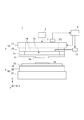
まず、本発明の第1実施形態に係るインプリント装置について説明する。図1は、インプリント装置の構成を示す図である。本実施形態におけるインプリント装置は、物品としての半導体デバイスなどのデバイスの製造に使用され、被処理基板であるウエハ上(基板上)の未硬化樹脂をモールド(型)で成形し、ウエハ上に樹脂のパターンを形成する装置である。なお、ここでは光硬化法を採用したインプリント装置とする。また、以下の図においては、ウエハ上の樹脂に対して紫外線を照射する照明系の光軸に平行にZ軸を取り、Z軸に垂直な平面内に互いに直交するX軸およびY軸を取っている。インプリント装置1は、まず、光照射部2と、モールド保持機構3と、ウエハステージ4と、塗布部と、制御部5とを備える。
(First embodiment)
First, the imprint apparatus according to the first embodiment of the present invention will be described. FIG. 1 is a diagram illustrating a configuration of an imprint apparatus. The imprint apparatus in the present embodiment is used for manufacturing a device such as a semiconductor device as an article, and an uncured resin on a wafer (on a substrate) that is a substrate to be processed is molded with a mold (mold). An apparatus for forming a resin pattern. Here, an imprint apparatus employing a photocuring method is used. In the following figures, the Z axis is taken parallel to the optical axis of the illumination system that irradiates the resin on the wafer with ultraviolet rays, and the X axis and Y axis perpendicular to each other are taken in a plane perpendicular to the Z axis. ing. First, the
光照射部2は、インプリント処理の際に、モールド6に対して紫外線7を照射する。この光照射部2は、不図示の光源と、この光源から射出された紫外線7をインプリントに適切な光に調整するための光学素子とから構成される。なお、本実施形態では光硬化法を採用するために光照射部2を設置しているが、例えば熱硬化法を採用する場合には、光照射部2に換えて、熱硬化性樹脂を硬化させるための熱源部を設置することとなる。
The
モールド6は、外周形状が矩形であり、ウエハ10に対する面に3次元状に形成されたパターン部(例えば、回路パターンなどの転写すべき凹凸パターン)6aを含む。また、モールド6の材質は、石英など紫外線7を透過させることが可能な材料である。さらに、モールド6は、以下のような変形を容易とするために、紫外線7が照射される面に、平面形状が円形で、かつ、ある程度の深さを有するキャビティ(凹部)が形成された形状としてもよい。
The
モールド保持機構(型保持機構)3は、まず、モールド6を保持するモールドチャック11と、このモールドチャック11を保持し、モールド6(モールドチャック11)を移動させるモールド駆動機構12とを有する。モールドチャック11は、モールド6における紫外線7の照射面の外周領域を真空吸着力や静電力により引き付けることでモールド6を保持し得る。例えば、モールドチャック11が真空吸着力によりモールド6を保持する場合には、モールドチャック11は、外部に設置された不図示の真空ポンプに接続され、この真空ポンプのON/OFFによりモールド6の脱着が切り替えられる。また、モールドチャック11およびモールド駆動機構12は、光照射部2から射出された紫外線7がウエハ10に向けて照射されるように、中心部(内側)に開口領域を有する。この開口領域には、開口領域の一部とモールド6とで囲まれる空間13を密閉空間とする光透過部材(例えばガラス板)14が設置され、真空ポンプなどを含む圧力調整装置(圧力調整部)15により空間13内の圧力が調整される。圧力調整装置15は、例えば、モールド6とウエハ10上の樹脂16との押し付けに際し、空間13内の圧力をその外部よりも高く設定することで、パターン部6aをウエハ10に向かい凸形に撓ませ、樹脂16に対してパターン部6aの中心部から接触させる。これにより、パターン部6aと樹脂16との間に気体(空気)が閉じ込められるのを抑え、パターン部6aの凹凸部に樹脂16を隅々まで充填させることができる。さらに、モールド保持機構3は、不図示であるが、モールドチャック11におけるモールド6の保持側に、モールド6の側面に外力または変位を与えることによりモールド6(パターン部6a)の形状を補正する倍率補正機構を有する。
Mold holding mechanism (mold holding mechanism) 3 first has a mold chucking click 1 1 that holds the
モールド駆動機構12は、モールド6とウエハ10上の樹脂16との押し付け、または引き離しを選択的に行うようにモールド6を各軸方向に移動させる。このモールド駆動機構12は、粗動型ステージ(粗動駆動系)17と、微動型ステージ(微動駆動系)18とから構成される。粗動型ステージ17は、主にZ軸方向に長距離駆動する。一方、微動型ステージ18は、粗動型ステージ17に追従し、主に6軸(X、Y、Z、ωx、ωy、ωz)方向に微小駆動する。なお、モールド駆動機構12に採用可能なアクチュエータとしては、例えばリニアモータやエアシリンダがある。また、インプリント装置1における押し付けおよび引き離し動作は、モールド6をZ軸方向に移動させることで実現してもよいが、ウエハステージ4をZ軸方向に移動させることで実現してもよく、または、その双方を相対的に移動させてもよい。
The
ウエハ10は、例えば、単結晶シリコン基板やSOI(Silicon on Insulator)基板であり、この被処理面には、モールド6に形成されたパターン部6aにより成形される紫外線硬化樹脂(以下「樹脂」という)16が塗布される。
The
ウエハステージ(基板保持部)4は、ウエハ10を保持し、モールド6とウエハ10上の樹脂16との押し付けに際し、モールド6と樹脂16との位置合わせを実施する。このウエハステージ4は、ウエハ10を、吸着力により保持するウエハチャック19と、このウエハチャック19を機械的手段により保持し、各軸方向に移動可能とするステージ駆動機構20とを有する。このステージ駆動機構20も、粗動型ステージ(粗動駆動系)21と、微動型ステージ(微動駆動系)22とから構成される。この場合、粗動型ステージ21は、主にXY平面内で長距離駆動する。一方、微動型ステージ22は、粗動型ステージ21に追従し、主に6軸(X、Y、Z、ωx、ωy、ωz)方向に微小駆動する。なお、ステージ駆動機構20に採用可能なアクチュエータとしては、例えばリニアモータや平面モータがある。
The wafer stage (substrate holding unit) 4 holds the
塗布部は、不図示であるが、モールド保持機構3の近傍に設置され、ウエハ10上に樹脂(未硬化樹脂)16を塗布する。ここで、この樹脂16は、紫外線7を受光することにより硬化する性質を有する光硬化性樹脂(インプリント材)であり、半導体デバイス製造工程などの各種条件により適宜選択される。また、塗布部の吐出ノズルから吐出される樹脂16の量も、ウエハ10上に形成される樹脂16の所望の厚さや、形成されるパターンの密度などにより適宜決定される。なお、以下の説明で使用する「パターン形成領域(ショット)」は、便宜上、樹脂16の塗布領域と略同一面積であるものと仮定する。
Although not shown, the application unit is installed in the vicinity of the
制御部5は、インプリント装置1の各構成要素の動作および調整などを制御し得る。制御部5は、例えば、コンピュータなどで構成され、インプリント装置1の各構成要素に回線を介して接続され、プログラムなどにしたがって各構成要素の制御を実行し得る。本実施形態の制御部5は、少なくともモールド保持機構3などの駆動部および圧力調整装置15の動作を制御する。なお、制御部5は、インプリント装置1の他の部分と一体で(共通の筐体内に)構成してもよいし、インプリント装置1の他の部分とは別体で(別の筐体内に)構成してもよい。
The
また、インプリント装置1は、モールド保持機構3の上方、すなわち紫外線7の照射方向の上流側に、モールド6(パターン部6a)とウエハ10上の樹脂16とが接触している際の接触領域の状態を把握するための測定装置(測定部)23を備える。この測定装置23は、例えばCCDカメラなどの撮像装置であり、この場合には接触領域を画像情報として取得する。また、インプリント装置1は、不図示であるが、アライメント計測系や、モールド6を装置外部からモールド保持機構3へ搬送するモールド搬送機構、または、ウエハ10を装置外部からウエハステージ4へ搬送する基板搬送機構などを含み得る。
Further, the
次に、インプリント装置1によるインプリント処理について説明する。まず、制御部5は、基板搬送機構によりウエハステージ4上のウエハチャック19にウエハ10を載置および固定させ、ウエハステージ4を塗布部の塗布位置へ移動させる。次に、塗布部は、塗布工程として、ウエハ10の所定の被処理領域であるパターン形成領域に樹脂16を塗布する。次に、制御部5は、ウエハ10上の前記パターン形成領域がモールド6に形成されたパターン部6aの直下に位置するようにウエハステージ4を移動させる。次に、制御部5は、モールド駆動機構12を駆動させ、ウエハ10上の樹脂16にモールド6を押し付ける(押型工程)。この押し付けにより、樹脂16は、パターン部6aの凹凸部に充填される。この状態で、制御部5は、硬化工程として、光照射部2にモールド6の上面から紫外線7を照射させ、モールド6を透過した紫外線7により樹脂16を硬化させる。そして、樹脂16が硬化した後に、制御部5は、モールド駆動機構12を再駆動させ、モールド6を樹脂16から引き離す(離型工程)。これにより、ウエハ10上の前記パターン形成領域の表面には、パターン部6aの凹凸部に倣った3次元形状の樹脂16のパターン(層)が成形される。このような一連のインプリント動作をウエハステージ4の駆動によりパターン形成領域を変更しつつ複数回実施することで、1枚のウエハ10上に複数の樹脂16のパターンを成形することができる。
Next, imprint processing by the
特に、上記押型工程および離型工程では、制御部5は、上述のとおり圧力調整装置15によりモールド6をウエハ10に向かい凸形に変形させる(撓ませる)。ここで、比較のために従来のインプリント装置における引き離し動作について説明する。図10は、従来のインプリント装置における引き離し動作時の状態を示す概略図である。特に、図10(a)は、引き離し動作時に、ウエハ100上に形成されたパターン形成領域である樹脂層101からモールド102(パターン部103)を引き離す途中の状態を示す図である。通常、モールド102をウエハ100から引き離す際は、モールド102は、ウエハ100から離れる方向、すなわちZ軸上方向の力を受ける。同時に、パターン部103と樹脂層101とが接触(固着)している接触領域では、モールド102は、ウエハ100へ向かう方向、すなわちZ軸下方向の引き離し応力を受ける。したがって、従来のインプリント装置では、図10(a)に示すように、モールド102をウエハ100に向かい凸形に変形させることで、パターン部103を樹脂層101の周囲から中心に向かって徐々に引き離し、引き離し応力の急激な発生を回避する。この引き離し動作の進行に伴い、パターン部103と樹脂層101との接触領域は、徐々に小さくなり、最終的にパターン部103と樹脂層101とが完全に離れると消滅する。
In particular, in the pressing process and the releasing process, the
しかしながら、この従来のインプリント装置では、モールド102の撓み状態やパターンのレイアウトによっては、引き離し動作の途中で接触領域の図心が樹脂層101の中心からずれる可能性がある。図10(b)は、このような場合の接触領域の状態を示す平面図である。例えば、接触領域104の位置がXY平面で偏っている、すなわち接触領域104の図心105が樹脂層101の中心106からずれている場合、接触領域104の境界107と樹脂層101の端部101aとの距離が近い部分でモールド102の反りが大きくなる。このモールド102の反りが大きくなることに伴って、モールド102に形成されたパターン部103の傾きも大きくなる。図10(c)は、接触領域104の境界107の近傍を示す拡大断面図である。このように、パターン部103の凹凸103aが樹脂層101に形成されたパターン101aと接触することで、パターン101aを変形させたり破損させたりするなどの欠陥が発生する可能性がある。そこで、本実施形態のインプリント装置1では、引き離し動作中に、接触領域の位置がXY平面で偏らないように、接触領域の図心の位置を適宜調整する。
However, in this conventional imprint apparatus, depending on the bending state of the
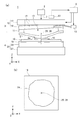
図2は、離型工程における図心調整前の接触領域の状態を示す概略図である。特に、図2(a)は、モールド6が変形状態にある図1に対応したインプリント装置1の状態を示す断面図であり、図2(b)は、このときのパターン部6aと樹脂(樹脂層)16との接触領域24の状態を示す平面図である。また、図3は、この離型工程におけるインプリント装置1の動作シーケンスを示すフローチャートである。まず、離型工程において、制御部5は、測定装置23により、引き離しを実施している間に渡り、接触領域24の画像情報を取得する(ステップS100)。次に、制御部5は、取得した画像情報に基づいて、接触領域24の図心25の位置(平面座標)を算出する(ステップS101)。この図心25の位置は、例えば、取得した接触領域24の面積を、多角形、円、楕円などに適宜置き換えることで算出可能である。なお、制御部5は、図心25を算出するに先立ち、ウエハ10上に塗布された樹脂16の面積、すなわちパターン形成領域の中心26の位置(平面座標)を算出しておく。次に、制御部5は、算出した図心25と中心26との位置を比較する(ステップS102)。そして、制御部5は、引き離し動作中には、図心25の位置が常に中心26の位置に向かう(合致する)ように、モールド駆動機構12の駆動系(駆動部)である微動型ステージ18を駆動させる(ステップS103)。このとき、制御部5は、モールド駆動機構12の粗動型ステージ17をZ軸方向に上昇させながら、微動型ステージ18におけるモールド保持面のXY軸周りの角度ωx、ωyを変化させる。そして、制御部5は、この一連の動作を所定の頻度で繰り返し(No)、引き離し動作が終了したと判断したら、動作シーケンスを終了する(ステップS104)。
FIG. 2 is a schematic diagram showing the state of the contact area before the centroid adjustment in the mold release step. 2A is a cross-sectional view showing the state of the
図4は、離型工程における図心調整中の接触領域の状態を示す概略図である。特に、図4(a)は、微動型ステージ18が駆動状態にある、図2に対応したインプリント装置1の状態を示す断面図であり、図4(b)は、このときのパターン部6aと樹脂(樹脂層)16との接触領域24の状態を示す平面図である。制御部5は、例えば、図4(a)に示すように、微動型ステージ18に対して、モールド6の保持面のY軸周りの角度ωyを変化させることで、この微動型ステージ18にモールドチャック11を介して保持されたモールド6(パターン部6a)の姿勢を変化させる。ここで、角度ωx、ωyの変化量は、図心25と中心26とのXY平面のオフセット量に基づいて調整される。制御部5は、このように算出したオフセット量に基づいて角度を調整させることで、図4(b)に示すように図心25の位置が移動し、図心25と中心26との位置が合致する。また、制御部5は、図心25の算出タイミングを、図心25の位置制御の精度が保たれ、かつ、微動型ステージ18のモールド保持面の角度の変化量が大きくなり過ぎないように予め設定する。例えば、パターン形成領域のサイズが20×30mmで、また引き離しに要する時間が0.1secであるとすると、制御部5は、図心25の算出を1msecごとに実行することが望ましい。制御部5は、このようなタイミングにて図心25を算出し、微動型ステージ18のモールド保持面の角度の変化量をフィードバック制御することで、図心25の位置制御の精度が維持される。
FIG. 4 is a schematic diagram showing the state of the contact area during centroid adjustment in the mold release step. 4A is a cross-sectional view showing a state of the
ここで、引き離し動作が進行し、接触領域24の面積が減少するのに伴い、引き離しに要する微動型ステージ18の駆動力は小さくなる。これに対して、制御部5が微動型ステージ18の駆動力を一定として制御すると、接触領域24の面積の減少に伴い、パターン部6aが樹脂16から急速に剥がれ、パターン欠陥を発生させる可能性がある。そこで、制御部5は、接触領域24の境界27の移動速度を算出し、この移動速度が一定となるように微動型ステージ18の駆動力を制御することが望ましい。この場合、必ずしも図心25の位置が常に中心26の位置に向かうように微動型ステージ18を駆動させなくとも、急速な剥がれに起因したパターン欠陥の発生を抑えることができる。
Here, as the separation operation proceeds and the area of the
このように、引き離し動作中に、図心25の位置が常に中心26の位置に向かうように微動型ステージ18を駆動させることで、接触領域24がXY平面において偏った位置となることを防ぐことができる。したがって、離型工程では、モールド6の撓みは、中心26から均等となるので、パターン部6aの傾きが局所的に大きくならず、結果的にパターン欠陥の発生を抑えることができる。また、引き離し動作の進行に伴い、接触領域24がXY平面にて偏った位置となることなく徐々に縮小していくので、接触領域24の境界27での移動速度は、中心26を基準として対称となる。したがって、引き離し動作中には境界27での移動速度が局所的に大きくなり過ぎないので、パターン部6aが樹脂16から急速に剥がれる部分が生じづらく、このような引き離し速度の観点からもパターン欠陥の発生を抑えることができる。
In this way, during the pulling operation, the fine
以上のように、本実施形態によれば、例えば、パターン欠陥の発生を抑えるのに有利なインプリント装置を提供することができる。 As described above, according to the present embodiment, for example, an imprint apparatus that is advantageous for suppressing the occurrence of pattern defects can be provided.
なお、本実施形態では、接触領域24の図心25の位置を樹脂16の中心26の位置に向かうように駆動する駆動部として、モールド6側の微動型ステージ18を用いたが、ウエハ10側の微動型ステージ22を用いてもよい。この場合、ステージ駆動機構20の粗動型ステージ21と微動型ステージ22とが、上記の説明におけるモールド駆動機構12の粗動型ステージ17と微動型ステージ18とにそれぞれ対応し、動作することになる。
In the present embodiment, the fine
(第2実施形態)
次に、本発明の第2実施形態に係るインプリント装置について説明する。図5は、本実施形態に係る離型工程における図心調整前のインプリント装置30の状態を示す概略図である。特に、図5(a)は、インプリント装置30の構成に関する状態を示す断面図である。なお、図5において、図1に示す第1実施形態に係るインプリント装置1の構成要素と同一のものには同一の符号を付し、説明を省略する。このインプリント装置30の特徴は、接触領域24の図心25の位置を樹脂16の中心26の位置に向かうように駆動する駆動部として、吸着面にて複数の吸着溝31を有するモールドチャック32を用いる点にある。この場合、第1実施形態のモールド駆動機構12に対応する本実施形態のモールド駆動機構33は、粗動型ステージと微動型ステージとの2つの駆動系を有するものではなく、少なくともZ軸方向に駆動可能とする単一型の駆動機構であってもよい。同様に、第1実施形態のステージ駆動機構20に対応する本実施形態のステージ駆動機構34も、粗動型ステージと微動型ステージとの2つの駆動系を有するものではなく、少なくともXY軸方向に駆動可能とする単一型の駆動機構であってもよい。
(Second Embodiment)
Next, an imprint apparatus according to the second embodiment of the present invention will be described. FIG. 5 is a schematic diagram illustrating a state of the
図5(b)は、モールド6側から見たモールドチャック32の構成、およびこの場合の吸着状態を示す平面図である。このモールドチャック32は、吸着面35のXY平面内の四方の領域(第1領域35a〜第4領域35d)のそれぞれに、一例として、内側から外側に向けて平行に配列された3つの吸着溝31を有する。これらの吸着溝31は、X軸方向の第1領域35aに配置される第1吸着溝31a〜第3吸着溝31c、および第1領域35aに対向する第2領域35bに配置される第4吸着溝31d〜第6吸着溝31fを含む。さらに、吸着溝31は、Y軸方向の第3領域35cに配置される第7吸着溝31g〜第9吸着溝31i、および第3領域35cに対向する第4領域35dに配置される第10吸着溝31j〜第12吸着溝31lを含む。これらの各吸着溝31は、それぞれ切り替え機構を介して真空ポンプ36に接続され、モールド6を吸着保持する際に、制御部5によりそれぞれ独立して吸着のON/OFFが切り替えられる。ここで、図5に示す例では、制御部5は、X軸方向の第1吸着溝31aと、この第1吸着溝31aに対向する第4吸着溝31dとの2つの吸着溝31の吸着をONとしている。なお、図中では、説明上、この吸着がONとなっている吸着溝31を黒塗りで示している。
FIG. 5B is a plan view showing the configuration of the
一方、図6は、本実施形態に係る離型工程における図心調整中のインプリント装置30の状態を示す概略図である。特に、図6(a)は、図5(a)に対応し、同様に、図6(b)は、図5(b)に対応している。第1実施形態では、制御部5は、図3に示す動作シーケンスにおけるステップS103にて、モールド駆動機構12の微動型ステージ18を駆動させることで、図心25の位置が常に中心26の位置に向かうように制御する。これに対して、本実施形態では、制御部5は、モールドチャック32の複数の吸着溝31において、吸着をONとする部分を切り替えることで、図心25の位置が常に中心26の位置に向かうように制御する。例えば、図6に示す例では、制御部5は、図5に示す吸着状態から、第1吸着溝31aでの吸着をそのままONとし、一方、第4吸着溝31dでの吸着をOFFとして、その外側に隣設する第5吸着溝31eでの吸着をONとするような吸着状態に変更する。このとき、吸着溝31の選択は、接触領域24の図心25と中心26とのXY平面のオフセット量に基づいて調整される。このように複数の吸着溝31の吸着動作をそれぞれ切り替えることで、モールド6の撓み形状が変化するのでパターン部6aの姿勢が変わり、結果的に接触領域24の図心25の位置を引き離し動作中に移動させることができる。これにより、本実施形態によれば、第1実施形態と同様の効果を奏する。
On the other hand, FIG. 6 is a schematic diagram showing a state of the
(第3実施形態)
次に、本発明の第3実施形態に係るインプリント装置について説明する。図7は、本実施形態に係る離型工程における図心調整前および図心調整中のインプリント装置40の状態を示す概略図である。特に、図7(a)は、図心調整前のインプリント装置40の状態を示す断面図である。なお、図7において、図1に示す第1実施形態に係るインプリント装置1の構成要素と同一のものには同一の符号を付し、説明を省略する。このインプリント装置40の特徴は、接触領域24の図心25の位置を樹脂16の中心26の位置に向かうように駆動する機構として、モールド41をモールドチャック42に吸着保持させたままXY軸方向に移動させる移動機構43を有する点にある。なお、この場合も、第1実施形態のモールド駆動機構12に対応する本実施形態のモールド駆動機構44は、粗動型ステージと微動型ステージとの2つの駆動系を有するものではなく、少なくともZ軸方向に駆動可能とする単一型の駆動機構であってもよい。同様に、第1実施形態のステージ駆動機構20に対応する本実施形態のステージ駆動機構45も、粗動型ステージと微動型ステージとの2つの駆動系を有するものではなく、少なくともXY軸方向に駆動可能とする単一型の駆動機構であってもよい。
(Third embodiment)
Next, an imprint apparatus according to a third embodiment of the present invention will be described. FIG. 7 is a schematic diagram illustrating a state of the
まず、本実施形態のモールド41の形状は、上記実施形態のモールド6の形状と比較して、外形およびパターン部41aの形状について同様であるが、モールドチャック42に対する吸着面を含む外周部の形状が異なる。すなわち、モールド41の中央部は、ウエハ10に向かい凸形に変形しやすいように薄く、その外周部は、より厚みのある壁部41bで形成されている。結果的に、モールド41の形状は、紫外線7の照射面の中央部に、平面形状が円形で、かつ、ある程度の深さを有するキャビティ(凹部)が形成された形状となる。これに対して、移動機構43は、例えばモールド駆動機構44に設置され、四方の壁部41bの壁面に対して独立して外圧を与えることで、XY軸方向にモールド41を移動させる。この移動機構43としては、例えば、図7(a)に示すように、壁部41bの内側と外側とにそれぞれ接触する、対となる突き当て棒46(46a、46b)を備え、内部に設置されるアクチュエータにより各突き当て棒46をXY軸方向に駆動する構成があり得る。
First, the shape of the
一方、図7(b)は、図心調整中のインプリント装置40の状態を示す断面図である。本実施形態では、制御部5は、移動機構43による四方の突き当て棒46の押し出し量を適宜調整することで、図心25の位置が常に中心26の位置に向かうように制御する。例えば、図7に示す例では、制御部5は、図7(a)に示す突き当て棒46の状態から、X軸方向において、一方の側の突き当て棒46の状態をそのままとし、他方の側の突き当て棒46の状態を、壁部41bが内側に向かうように押し出す状態に変更する。このとき、突き当て棒46の押し出し量は、接触領域24の図心25と中心26とのXY平面のオフセット量に基づいて調整される。このように移動機構43による外圧の付加によりモールド41の撓み形状が変化するので、パターン部41aの姿勢が変わり、結果的に接触領域24の図心25の位置を引き離し動作中に移動させることができる。これにより、本実施形態によれば、第1実施形態と同様の効果を奏する。
On the other hand, FIG. 7B is a cross-sectional view showing a state of the
(第4実施形態)
次に、本発明の第4実施形態に係るインプリント装置について説明する。図8は、本実施形態に係る離型工程における図心調整前のインプリント装置50の状態を示す概略図である。なお、図8において、図1に示す第1実施形態に係るインプリント装置1の構成要素と同一のものには同一の符号を付し、説明を省略する。このインプリント装置50の特徴は、上記各実施形態に係るインプリント装置の構成にさらに荷重計測部51を加え、この荷重計測部51の計測値に基づいて、引き離し動作時にウエハ10がウエハチャック19から浮き上がるのを抑える点にある。特に、荷重計測部51は、引き離し動作時のモールド6にかかる荷重を計測可能とすることが望ましい。例えば、荷重計測部51は、ロードセルなどの計測装置とし、モールド駆動機構12と、このモールド駆動機構12を支持するインプリント装置50内の不図示の固定部(例えばブリッジ定盤)との間に設置される。そして、荷重計測部51は、測定装置23と同様に、制御部5に接続される。
(Fourth embodiment)
Next, an imprint apparatus according to a fourth embodiment of the present invention will be described. FIG. 8 is a schematic diagram showing a state of the
本実施形態の離型工程では、制御部5は、まず上記実施形態と同様に、測定装置23により接触領域24の画像情報を取得し、取得した画像情報に基づいて接触領域24の面積を算出する。さらに、制御部5は、荷重計測部51に対してモールド6にかかる荷重を計測させ、その計測値を取得する。ここで、測定装置23が取得した画像情報に基づく接触領域24の面積をScとし、荷重計測部51が計測した計測値に基づくモールド6にかかる荷重をFmとし、さらにウエハ10を吸着保持する際のウエハチャック19による吸着圧力を−pwとする。荷重Fmは、引き離し動作時には接触領域24を介してウエハ10をウエハチャック19から引き離す方向に働く。このとき、荷重Fmが、接触領域24に相対するウエハ10の裏面の領域にかかるウエハチャック19による吸着力(吸着圧力と接触面積とを乗じた値:pw・Sc)よりも小さい場合には、ウエハ10は、ウエハチャック19に正常に吸着保持されている。しかしながら、荷重Fmが吸着力pw・Scよりも大きくなると、ウエハ10をウエハチャック19から引き離す方向の力がウエハ10をウエハチャック19に吸着する力よりも大きくなるので、ウエハ10がウエハチャック19から浮き上がる。そこで、本実施形態では、制御部5は、離型工程においてFm<pw・Scの関係を維持するように、引き離し時のモールド駆動機構12の動作を制御する。
In the mold release process of the present embodiment, the
このときのモールド駆動機構12の動作制御に関連し、図9に参考図を示す。特に、図9(a)は、引き離し動作の進行に伴う接触領域24の変化を示す平面図である。上述のとおり、引き離し動作時には、モールド6は、ウエハ10に向かい凸形に撓み、樹脂16の端部から中心に向かって徐々に剥がれていく。すなわち、図9(a)に示すように、引き離し中のある時点における接触領域24に対して、さらに時間が経過して引き離し動作が進行すると、接触領域24aのように剥離する範囲が狭まる。このモールド6が樹脂16から剥離するときの接触領域24の境界の移動速度が速くなるほど、一定時間に剥離する範囲は広くなり、結果的にモールド6にかかる荷重Fmが大きくなる。そこで、制御部5は、モールド6と樹脂16(ウエハ10)とが離れる際の相対速度、すなわち本実施形態ではモールド駆動機構12によるモールド6をZ軸方向に上昇させる速度を制御することで、接触領域24の境界の移動速度を適切に変化させる。これにより、モールド6にかかる荷重Fmを調整することが可能となり、本実施形態によれば、上記実施形態と同様の効果を奏するとともに、離型工程においてウエハ10がウエハチャック19から浮き上がることを抑止することができる。
FIG. 9 shows a reference diagram related to the operation control of the
なお、本実施形態の効果は、ウエハ10上の特定の位置に存在するショットSにて特に好適に発揮される。図9(b)は、一例として、ウエハ10上の3つのショットS1、S2、S3の位置を示す平面図である。このうち、ショットS2やショットS3のように、ウエハ10上の比較的端部に位置するショットSに対してインプリント処理を実施する場合に、特に本実施形態は好適である。すなわち、このウエハ10上の端部に位置するショットSにてウエハ10の浮き上がりを抑えることができれば、ウエハ10とウエハチャック19との隙間に外気が流入してウエハチャック19の吸着力が減少することをも抑えることができる。これにより、インプリント装置50は、ウエハ10が、ウエハチャック19に対して位置ずれを起こしたり、ウエハチャック19から剥がれたりすることを予め回避させることができる。
Note that the effect of the present embodiment is particularly preferably exhibited by the shot S existing at a specific position on the
(物品の製造方法)
物品としてのデバイス(半導体集積回路素子、液晶表示素子等)の製造方法は、上述したインプリント装置を用いて基板(ウエハ、ガラスプレート、フィルム状基板)にパターンを形成する工程を含む。さらに、該製造方法は、パターンを形成された基板をエッチングする工程を含み得る。なお、パターンドメディア(記録媒体)や光学素子などの他の物品を製造する場合には、該製造方法は、エッチングの代わりにパターンを形成された基板を加工する他の処理を含み得る。本実施形態の物品の製造方法は、従来の方法に比べて、物品の性能・品質・生産性・生産コストの少なくとも1つにおいて有利である。
(Product manufacturing method)
A method for manufacturing a device (semiconductor integrated circuit element, liquid crystal display element, etc.) as an article includes a step of forming a pattern on a substrate (wafer, glass plate, film-like substrate) using the above-described imprint apparatus. Furthermore, the manufacturing method may include a step of etching the substrate on which the pattern is formed. In the case of manufacturing other articles such as patterned media (recording media) and optical elements, the manufacturing method may include other processes for processing a substrate on which a pattern is formed instead of etching. The method for manufacturing an article according to the present embodiment is advantageous in at least one of the performance, quality, productivity, and production cost of the article as compared with the conventional method.
以上、本発明の好ましい実施形態について説明したが、本発明は、これらの実施形態に限定されず、その要旨の範囲内で種々の変形および変更が可能である。 As mentioned above, although preferable embodiment of this invention was described, this invention is not limited to these embodiment, A various deformation | transformation and change are possible within the range of the summary.
1 インプリント装置
3 モールド保持機構
4 ウエハステージ
5 制御部
6 モールド
10 ウエハ
11 モールドチャック
15 圧力調整装置
16 樹脂
18 微動型ステージ
23 測定装置
24 接触領域
DESCRIPTION OF
Claims (8)
前記型を保持する型保持機構と、
前記基板を保持する基板保持部と、
前記型保持機構に保持された状態の前記型を、該型に接する空間の圧力を調整することで前記基板に向かい凸形に変形させる圧力調整部と、
前記凸形に変形した前記型と前記樹脂とが接触している際の接触領域の状態を示す画像を取得する測定部と、
前記接触領域の位置を移動させるための駆動部と、
前記型を前記樹脂から前記引き離す場合に、前記測定部により取得された画像情報に基づいて前記接触領域の図心の平面座標を求め、該図心の平面座標の位置が予め取得した前記基板上のパターン形成領域の中心の平面座標の位置に向かうように前記駆動部の動作を制御する制御部と、
を有することを特徴とするインプリント装置。 An imprint apparatus that forms a pattern of a cured resin on the substrate by curing the uncured resin on the substrate in a state where the mold is in contact and pulling the mold away from the cured resin,
A mold holding mechanism for holding the mold;
A substrate holder for holding the substrate;
A pressure adjusting unit that deforms the mold held by the mold holding mechanism into a convex shape toward the substrate by adjusting a pressure of a space in contact with the mold;
A measurement unit that acquires an image indicating a state of a contact area when the resin deformed into the convex shape and the resin are in contact;
A drive unit for moving the position of the contact area;
When the mold is separated from the resin , a plane coordinate of the centroid of the contact area is obtained based on the image information acquired by the measurement unit , and the position of the plane coordinate of the centroid is acquired on the substrate in advance. A control unit for controlling the operation of the driving unit so as to go to the position of the plane coordinate at the center of the pattern forming region ;
An imprint apparatus comprising:
前記型を保持する型保持機構と、
前記基板を保持する基板保持部と、
前記型保持機構に保持された状態の前記型を、該型に接する空間の圧力を調整することで前記基板に向かい凸形に変形させる圧力調整部と、
前記凸形に変形した前記型と前記樹脂とが接触している際の接触領域の状態を示す画像を取得する測定部と、
前記接触領域の位置を移動させるための駆動部と、
前記型を前記樹脂から前記引き離す場合に、前記測定部により取得された画像情報に基づいて前記駆動部の動作を制御する制御部と、を有し、
前記駆動部は、前記型保持機構に設置され、前記型保持機構の前記型を保持する保持面の角度を変化させるアクチュエータであることを特徴とするインプリント装置。 An imprint apparatus that forms a pattern of a cured resin on the substrate by curing the uncured resin on the substrate in a state where the mold is in contact, and separating the mold from the cured resin,
A mold holding mechanism for holding the mold;
A substrate holder for holding the substrate;
A pressure adjusting unit that deforms the mold held by the mold holding mechanism into a convex shape toward the substrate by adjusting a pressure of a space in contact with the mold;
A measurement unit that acquires an image indicating a state of a contact area when the resin deformed into the convex shape and the resin are in contact;
A drive unit for moving the position of the contact area;
A control unit for controlling the operation of the drive unit based on image information acquired by the measurement unit when the mold is separated from the resin;
The drive unit, the type installed in the holding mechanism, wherein the to Louis down printing device that is an actuator for changing the angle of the holding surface for holding the type of the previous SL-type retaining Organization.
前記型を保持する型保持機構と、
前記基板を保持する基板保持部と、
前記型保持機構に保持された状態の前記型を、該型に接する空間の圧力を調整することで前記基板に向かい凸形に変形させる圧力調整部と、
前記凸形に変形した前記型と前記樹脂とが接触している際の接触領域の状態を示す画像を取得する測定部と、
前記接触領域の位置を移動させるための駆動部と、
前記型を前記樹脂から前記引き離す場合に、前記測定部により取得された画像情報に基づいて前記駆動部の動作を制御する制御部と、を有し、
前記駆動部は、前記基板保持部に設置され、前記基板保持部の前記基板を保持する保持面の角度を変化させるアクチュエータであることを特徴とするインプリント装置。 An imprint apparatus that forms a pattern of a cured resin on the substrate by curing the uncured resin on the substrate in a state where the mold is in contact, and separating the mold from the cured resin,
A mold holding mechanism for holding the mold;
A substrate holder for holding the substrate;
A pressure adjusting unit that deforms the mold held by the mold holding mechanism into a convex shape toward the substrate by adjusting a pressure of a space in contact with the mold;
A measurement unit that acquires an image indicating a state of a contact area when the resin deformed into the convex shape and the resin are in contact;
A drive unit for moving the position of the contact area;
A control unit for controlling the operation of the drive unit based on image information acquired by the measurement unit when the mold is separated from the resin;
The driving unit is configured is installed in the substrate holder, before Symbol features and to Louis down printing device that is an actuator for changing the angle of the holding surface for holding the substrate of the substrate holder.
前記型を保持する型保持機構と、
前記基板を保持する基板保持部と、
前記型保持機構に保持された状態の前記型を、該型に接する空間の圧力を調整することで前記基板に向かい凸形に変形させる圧力調整部と、
前記凸形に変形した前記型と前記樹脂とが接触している際の接触領域の状態を示す画像を取得する測定部と、
前記接触領域の位置を移動させるための駆動部と、
前記型を前記樹脂から前記引き離す場合に、前記測定部により取得された画像情報に基づいて前記駆動部の動作を制御する制御部と、を有し、
前記駆動部は、前記型を吸着する複数の吸着溝と、該複数の吸着溝のそれぞれの吸着状態を独立して切り替え可能とする切り替え機構とを含む前記型保持機構であることを特徴とするインプリント装置。 An imprint apparatus that forms a pattern of a cured resin on the substrate by curing the uncured resin on the substrate in a state where the mold is in contact, and separating the mold from the cured resin,
A mold holding mechanism for holding the mold;
A substrate holder for holding the substrate;
A pressure adjusting unit that deforms the mold held by the mold holding mechanism into a convex shape toward the substrate by adjusting a pressure of a space in contact with the mold;
A measurement unit that acquires an image indicating a state of a contact area when the resin deformed into the convex shape and the resin are in contact;
A drive unit for moving the position of the contact area;
A control unit for controlling the operation of the drive unit based on image information acquired by the measurement unit when the mold is separated from the resin;
The drive unit is the mold holding mechanism including a plurality of suction grooves that suck the mold and a switching mechanism that can switch the suction states of the plurality of suction grooves independently. Louis down the printing apparatus.
前記型を保持する型保持機構と、
前記基板を保持する基板保持部と、
前記型保持機構に保持された状態の前記型を、該型に接する空間の圧力を調整することで前記基板に向かい凸形に変形させる圧力調整部と、
前記凸形に変形した前記型と前記樹脂とが接触している際の接触領域の状態を示す画像を取得する測定部と、
前記接触領域の位置を移動させるための駆動部と、
前記型を前記樹脂から前記引き離す場合に、前記測定部により取得された画像情報に基づいて前記駆動部の動作を制御する制御部と、を有し、
前記駆動部は、前記型保持機構に保持されつつ前記基板に向かい凸形に変形した状態の前記型を、前記基板保持部の前記基板を保持する保持面に沿って移動させる移動機構であることを特徴とするインプリント装置。 An imprint apparatus that forms a pattern of a cured resin on the substrate by curing the uncured resin on the substrate in a state where the mold is in contact, and separating the mold from the cured resin,
A mold holding mechanism for holding the mold;
A substrate holder for holding the substrate;
A pressure adjusting unit that deforms the mold held by the mold holding mechanism into a convex shape toward the substrate by adjusting a pressure of a space in contact with the mold;
A measurement unit that acquires an image indicating a state of a contact area when the resin deformed into the convex shape and the resin are in contact;
A drive unit for moving the position of the contact area;
A control unit for controlling the operation of the drive unit based on image information acquired by the measurement unit when the mold is separated from the resin;
The drive unit is a moving mechanism that moves the mold in a state of being convexly deformed toward the substrate while being held by the mold holding mechanism along a holding surface that holds the substrate of the substrate holding unit. features and to Louis down printing apparatus.
前記型を保持する型保持機構と、
前記基板を保持する基板保持部と、
前記型保持機構に保持された状態の前記型を、該型に接する空間の圧力を調整することで前記基板に向かい凸形に変形させる圧力調整部と、
前記凸形に変形した前記型と前記樹脂とが接触している際の接触領域の状態を示す画像を取得する測定部と、
前記接触領域の位置を移動させるための駆動部と、
前記型を前記樹脂から前記引き離す場合に、前記測定部により取得された画像情報に基づいて前記駆動部の動作を制御する制御部と、
前記型にかかる荷重を計測する荷重計測部と、を有し、
前記制御部は、前記画像情報に基づいて、前記型を前記樹脂から前記引き離す場合の前記接触領域の面積を算出し、前記引き離す場合の前記荷重が前記基板保持部の吸着圧と前記接触領域の面積を乗じた値を越えないように、前記基板と前記型との相対速度を制御することを特徴とするインプリント装置。 An imprint apparatus that forms a pattern of a cured resin on the substrate by curing the uncured resin on the substrate in a state where the mold is in contact, and separating the mold from the cured resin,
A mold holding mechanism for holding the mold;
A substrate holder for holding the substrate;
A pressure adjusting unit that deforms the mold held by the mold holding mechanism into a convex shape toward the substrate by adjusting a pressure of a space in contact with the mold;
A measurement unit that acquires an image indicating a state of a contact area when the resin deformed into the convex shape and the resin are in contact;
A drive unit for moving the position of the contact area;
A control unit that controls the operation of the driving unit based on image information acquired by the measurement unit when the mold is separated from the resin;
Anda load measuring unit for measuring a load applied to the mold,
Wherein the control part, based on the image information, and calculates an area of the contact region when separating the said type from the resin, the contact the load when the pull away to the adsorption pressure of the substrate holder so as not to exceed a value obtained by multiplying the area of the region, features and be Louis down printing device to control the relative speed between the mold and the substrate.
前記工程で前記パターンを形成された基板を加工する工程と、
を含むことを特徴とする物品の製造方法。 Forming a resin pattern on a substrate using the imprint apparatus according to claim 1;
Processing the substrate on which the pattern is formed in the step;
A method for producing an article comprising:
Priority Applications (3)
| Application Number | Priority Date | Filing Date | Title |
|---|---|---|---|
| JP2012111419A JP6004738B2 (en) | 2011-09-07 | 2012-05-15 | Imprint apparatus and article manufacturing method using the same |
| US13/603,575 US9400426B2 (en) | 2011-09-07 | 2012-09-05 | Imprint apparatus |
| US15/191,715 US10095117B2 (en) | 2011-09-07 | 2016-06-24 | Imprint apparatus |
Applications Claiming Priority (3)
| Application Number | Priority Date | Filing Date | Title |
|---|---|---|---|
| JP2011194583 | 2011-09-07 | ||
| JP2011194583 | 2011-09-07 | ||
| JP2012111419A JP6004738B2 (en) | 2011-09-07 | 2012-05-15 | Imprint apparatus and article manufacturing method using the same |
Publications (3)
| Publication Number | Publication Date |
|---|---|
| JP2013070023A JP2013070023A (en) | 2013-04-18 |
| JP2013070023A5 JP2013070023A5 (en) | 2015-07-09 |
| JP6004738B2 true JP6004738B2 (en) | 2016-10-12 |
Family
ID=47752508
Family Applications (1)
| Application Number | Title | Priority Date | Filing Date |
|---|---|---|---|
| JP2012111419A Active JP6004738B2 (en) | 2011-09-07 | 2012-05-15 | Imprint apparatus and article manufacturing method using the same |
Country Status (2)
| Country | Link |
|---|---|
| US (2) | US9400426B2 (en) |
| JP (1) | JP6004738B2 (en) |
Cited By (1)
| Publication number | Priority date | Publication date | Assignee | Title |
|---|---|---|---|---|
| US11422462B2 (en) | 2019-06-07 | 2022-08-23 | Canon Kabushiki Kaisha | Forming apparatus that controls chucking force |
Families Citing this family (27)
| Publication number | Priority date | Publication date | Assignee | Title |
|---|---|---|---|---|
| JP6069689B2 (en) * | 2012-07-26 | 2017-02-01 | 大日本印刷株式会社 | Nanoimprint template |
| JP2014033050A (en) * | 2012-08-02 | 2014-02-20 | Toshiba Corp | Imprint system and imprint method |
| JP6271875B2 (en) * | 2013-06-18 | 2018-01-31 | キヤノン株式会社 | Imprint apparatus, imprint method, and article manufacturing method |
| JP6282069B2 (en) * | 2013-09-13 | 2018-02-21 | キヤノン株式会社 | Imprint apparatus, imprint method, detection method, and device manufacturing method |
| TWI690482B (en) | 2013-12-31 | 2020-04-11 | 佳能奈米科技股份有限公司 | Asymmetric template shape modulation for partial field imprinting |
| JP6497849B2 (en) * | 2014-04-15 | 2019-04-10 | キヤノン株式会社 | Imprint apparatus and article manufacturing method |
| CN106462053B (en) * | 2014-04-22 | 2020-12-01 | Ev 集团 E·索尔纳有限责任公司 | Method and apparatus for imprinting nanostructures |
| JP6472189B2 (en) * | 2014-08-14 | 2019-02-20 | キヤノン株式会社 | Imprint apparatus, imprint method, and article manufacturing method |
| JP6659104B2 (en) * | 2014-11-11 | 2020-03-04 | キヤノン株式会社 | Imprint method, imprint apparatus, mold, and article manufacturing method |
| JP6674218B2 (en) * | 2014-12-09 | 2020-04-01 | キヤノン株式会社 | Imprint apparatus, imprint method, and article manufacturing method |
| JP6478635B2 (en) | 2015-01-05 | 2019-03-06 | キヤノン株式会社 | Imprint apparatus, imprint method, and article manufacturing method |
| JP6553926B2 (en) * | 2015-04-09 | 2019-07-31 | キヤノン株式会社 | Imprint apparatus, imprint method, and article manufacturing method |
| JP6647027B2 (en) * | 2015-12-03 | 2020-02-14 | キヤノン株式会社 | Imprint apparatus and article manufacturing method |
| JP6942491B2 (en) * | 2016-03-15 | 2021-09-29 | キヤノン株式会社 | Imprinting equipment and manufacturing method of goods |
| KR101737817B1 (en) * | 2016-06-15 | 2017-05-19 | 울산과학기술원 | Nano material testing apparatus and method for testing material using the same |
| JP6706983B2 (en) | 2016-07-12 | 2020-06-10 | キヤノン株式会社 | Imprint apparatus and method of manufacturing article |
| JP2018041774A (en) * | 2016-09-05 | 2018-03-15 | キヤノン株式会社 | Imprint device and article manufacturing method |
| JP6762853B2 (en) * | 2016-11-11 | 2020-09-30 | キヤノン株式会社 | Equipment, methods, and article manufacturing methods |
| JP6940944B2 (en) * | 2016-12-06 | 2021-09-29 | キヤノン株式会社 | Imprint device and article manufacturing method |
| US10497667B2 (en) | 2017-09-26 | 2019-12-03 | Taiwan Semiconductor Manufacturing Co., Ltd. | Apparatus for bond wave propagation control |
| JP7033994B2 (en) * | 2018-04-11 | 2022-03-11 | キヤノン株式会社 | Molding equipment and manufacturing method of articles |
| JP7233174B2 (en) * | 2018-05-17 | 2023-03-06 | キヤノン株式会社 | Imprint apparatus, article manufacturing method, planarization layer forming apparatus, information processing apparatus, and determination method |
| JP7237519B2 (en) * | 2018-10-25 | 2023-03-13 | キヤノン株式会社 | Molding apparatus for molding composition on substrate using mold, molding method, and article manufacturing method |
| US11442359B2 (en) | 2019-03-11 | 2022-09-13 | Canon Kabushiki Kaisha | Method of separating a template from a shaped film on a substrate |
| US20220339825A1 (en) * | 2019-12-02 | 2022-10-27 | Ev Group E. Thallner Gmbh | Method and device for detaching a stamp |
| JP7414508B2 (en) * | 2019-12-16 | 2024-01-16 | キヤノン株式会社 | Imprint device and article manufacturing method |
| US11614693B2 (en) | 2021-06-30 | 2023-03-28 | Canon Kabushiki Kaisha | Method of determining the initial contact point for partial fields and method of shaping a surface |
Family Cites Families (14)
| Publication number | Priority date | Publication date | Assignee | Title |
|---|---|---|---|---|
| JPH10172897A (en) * | 1996-12-05 | 1998-06-26 | Nikon Corp | Substrate adaptor, substrate holder and method for holding substrate |
| US6900881B2 (en) * | 2002-07-11 | 2005-05-31 | Molecular Imprints, Inc. | Step and repeat imprint lithography systems |
| US7019819B2 (en) * | 2002-11-13 | 2006-03-28 | Molecular Imprints, Inc. | Chucking system for modulating shapes of substrates |
| MY164487A (en) * | 2002-07-11 | 2017-12-29 | Molecular Imprints Inc | Step and repeat imprint lithography processes |
| EP2099066B1 (en) * | 2002-11-13 | 2012-01-04 | Molecular Imprints, Inc. | Method for modulating shapes of substrates |
| JP5180820B2 (en) * | 2005-05-03 | 2013-04-10 | コーニンクレッカ フィリップス エレクトロニクス エヌ ヴィ | Method and apparatus for transferring a pattern from a stamp to a substrate |
| CN101573659A (en) | 2005-12-08 | 2009-11-04 | 分子制模股份有限公司 | Method for expelling gas positioned between a substrate and a mold |
| US8945444B2 (en) * | 2007-12-04 | 2015-02-03 | Canon Nanotechnologies, Inc. | High throughput imprint based on contact line motion tracking control |
| US8652393B2 (en) * | 2008-10-24 | 2014-02-18 | Molecular Imprints, Inc. | Strain and kinetics control during separation phase of imprint process |
| US8309008B2 (en) * | 2008-10-30 | 2012-11-13 | Molecular Imprints, Inc. | Separation in an imprint lithography process |
| JP4940262B2 (en) | 2009-03-25 | 2012-05-30 | 株式会社東芝 | Imprint pattern forming method |
| JP5669377B2 (en) * | 2009-11-09 | 2015-02-12 | キヤノン株式会社 | Imprint apparatus and article manufacturing method |
| JP5750992B2 (en) * | 2011-04-27 | 2015-07-22 | 大日本印刷株式会社 | Imprint method and imprint apparatus for implementing the method |
| JP5893303B2 (en) * | 2011-09-07 | 2016-03-23 | キヤノン株式会社 | Imprint apparatus and article manufacturing method using the same |
-
2012
- 2012-05-15 JP JP2012111419A patent/JP6004738B2/en active Active
- 2012-09-05 US US13/603,575 patent/US9400426B2/en active Active
-
2016
- 2016-06-24 US US15/191,715 patent/US10095117B2/en active Active
Cited By (1)
| Publication number | Priority date | Publication date | Assignee | Title |
|---|---|---|---|---|
| US11422462B2 (en) | 2019-06-07 | 2022-08-23 | Canon Kabushiki Kaisha | Forming apparatus that controls chucking force |
Also Published As
| Publication number | Publication date |
|---|---|
| US20160306281A1 (en) | 2016-10-20 |
| US10095117B2 (en) | 2018-10-09 |
| JP2013070023A (en) | 2013-04-18 |
| US9400426B2 (en) | 2016-07-26 |
| US20130056905A1 (en) | 2013-03-07 |
Similar Documents
| Publication | Publication Date | Title |
|---|---|---|
| JP6004738B2 (en) | Imprint apparatus and article manufacturing method using the same | |
| JP5893303B2 (en) | Imprint apparatus and article manufacturing method using the same | |
| JP5744590B2 (en) | Imprint method, mold, and manufacturing method of article using them | |
| JP6140966B2 (en) | Imprint apparatus and article manufacturing method using the same | |
| JP5759303B2 (en) | Imprint apparatus and article manufacturing method using the same | |
| JP6021606B2 (en) | Imprint apparatus, article manufacturing method using the same, and imprint method | |
| JP5787691B2 (en) | Imprint apparatus and article manufacturing method using the same | |
| JP5868215B2 (en) | Imprint apparatus, imprint method, and article manufacturing method using the same | |
| JP2012134214A (en) | Imprint apparatus and manufacturing method of goods | |
| TWI627050B (en) | Imprint method, imprint apparatus, mold, and semiconductor device manufacturing method | |
| JP5637785B2 (en) | Original plate and method of manufacturing article using the same | |
| JP2013008911A (en) | Cleaning method, imprint device using the same and manufacturing method of article | |
| JP6774178B2 (en) | Equipment for processing substrates and manufacturing methods for articles | |
| JP6423641B2 (en) | Imprint apparatus, article manufacturing method, and imprint method | |
| JP2017112230A (en) | Imprint device and article manufacturing method | |
| JP5822597B2 (en) | Imprint apparatus and article manufacturing method using the same | |
| JP2015220299A (en) | Imprint device and method of manufacturing article | |
| JP2014175620A (en) | Imprinting device, molding set, imprinting method, and article production method | |
| JP7023744B2 (en) | Imprint method and manufacturing method | |
| KR102367025B1 (en) | Molding apparatus for molding composition on substrate using mold and method of manufacturing article | |
| JP2013105902A (en) | Mold, imprint method using mold, and manufacturing method of goods | |
| JP2013062287A (en) | Mold, imprint method using the same, and method for manufacturing article |
Legal Events
| Date | Code | Title | Description |
|---|---|---|---|
| A621 | Written request for application examination |
Free format text: JAPANESE INTERMEDIATE CODE: A621 Effective date: 20150515 |
|
| A521 | Request for written amendment filed |
Free format text: JAPANESE INTERMEDIATE CODE: A523 Effective date: 20150525 |
|
| A131 | Notification of reasons for refusal |
Free format text: JAPANESE INTERMEDIATE CODE: A131 Effective date: 20160315 |
|
| A977 | Report on retrieval |
Free format text: JAPANESE INTERMEDIATE CODE: A971007 Effective date: 20160316 |
|
| A521 | Request for written amendment filed |
Free format text: JAPANESE INTERMEDIATE CODE: A523 Effective date: 20160511 |
|
| TRDD | Decision of grant or rejection written | ||
| A01 | Written decision to grant a patent or to grant a registration (utility model) |
Free format text: JAPANESE INTERMEDIATE CODE: A01 Effective date: 20160809 |
|
| A61 | First payment of annual fees (during grant procedure) |
Free format text: JAPANESE INTERMEDIATE CODE: A61 Effective date: 20160906 |
|
| R151 | Written notification of patent or utility model registration |
Ref document number: 6004738 Country of ref document: JP Free format text: JAPANESE INTERMEDIATE CODE: R151 |