JP5969663B2 - Peeling device, peeling system and peeling method - Google Patents
Peeling device, peeling system and peeling method Download PDFInfo
- Publication number
- JP5969663B2 JP5969663B2 JP2015120037A JP2015120037A JP5969663B2 JP 5969663 B2 JP5969663 B2 JP 5969663B2 JP 2015120037 A JP2015120037 A JP 2015120037A JP 2015120037 A JP2015120037 A JP 2015120037A JP 5969663 B2 JP5969663 B2 JP 5969663B2
- Authority
- JP
- Japan
- Prior art keywords
- substrate
- peeling
- unit
- superposed
- suction
- Prior art date
- Legal status (The legal status is an assumption and is not a legal conclusion. Google has not performed a legal analysis and makes no representation as to the accuracy of the status listed.)
- Active
Links
Images


Landscapes
- Container, Conveyance, Adherence, Positioning, Of Wafer (AREA)
Description
開示の実施形態は、剥離装置、剥離システムおよび剥離方法に関する。 The disclosed embodiments relate to a peeling apparatus, a peeling system, and a peeling method.
近年、たとえば、半導体デバイスの製造工程において、シリコンウェハや化合物半導体ウェハなどの半導体基板の大口径化および薄型化が進んでいる。大口径で薄い半導体基板は、搬送時や研磨処理時に反りや割れが生じるおそれがある。このため、半導体基板に支持基板を貼り合わせて補強した後に、搬送や研磨処理を行い、その後、支持基板を半導体基板から剥離する処理が行われている。 In recent years, for example, in the semiconductor device manufacturing process, semiconductor substrates such as silicon wafers and compound semiconductor wafers have become larger and thinner. A large-diameter and thin semiconductor substrate may be warped or cracked during transportation or polishing. For this reason, after a support substrate is bonded to a semiconductor substrate and reinforced, a transport or polishing process is performed, and then a process of peeling the support substrate from the semiconductor substrate is performed.
たとえば、特許文献1には、第1保持部を用いて半導体基板を保持するとともに、第2保持部を用いて支持基板を保持し、第2保持部の外周部を鉛直方向に移動させることにより、支持基板を半導体基板から剥離する技術が開示されている。
For example, in
しかしながら、上述した従来技術には、剥離処理の効率化を図るという点で更なる改善の余地があった。なお、かかる課題は、基板の剥離を伴うSOI(Silicon On Insulator)などの製造工程においても生じ得る課題である。 However, the above-described conventional technology has room for further improvement in terms of increasing the efficiency of the peeling process. Such a problem is a problem that may also occur in a manufacturing process such as SOI (Silicon On Insulator) that involves peeling of the substrate.
実施形態の一態様は、剥離処理の効率化を図ることのできる剥離装置、剥離システムおよび剥離方法を提供することを目的とする。 An object of one embodiment is to provide a peeling apparatus, a peeling system, and a peeling method that can improve the efficiency of a peeling process.
実施形態の一態様に係る剥離装置は、保持部と、複数の吸着移動部と、剥離誘引部と、押し下げ部と、状態検知部と、制御部とを備える。保持部は、第1基板と第2基板とが接合された重合基板のうち前記第1基板を保持する。複数の吸着移動部は、前記重合基板のうち前記第2基板を吸着し、前記第2基板を前記第1基板の板面から離す方向へ移動させる。剥離誘引部は、前記第2基板が前記第1基板から剥離するきっかけとなる部位を前記重合基板における一端側の側面に形成する。押し下げ部は、前記剥離誘引部の上方に配置されるとともに、前記重合基板よりも大径の開口部に張設される貼着部材に前記重合基板が張り付けられたダイシングフレームを押し下げる。状態検知部は、前記第2基板の前記第1基板からの剥離状態を検知する。制御部は、前記状態検知部によって検知された前記剥離状態に基づき、前記第2基板が該第2基板の一端から他端へ向けて前記第1基板から徐々に剥離するように、前記吸着移動部の動作タイミングを制御する。 A peeling apparatus according to an aspect of the embodiment includes a holding unit, a plurality of suction moving units, a peeling attraction unit, a push-down unit, a state detection unit, and a control unit. The holding unit holds the first substrate among the superposed substrates obtained by bonding the first substrate and the second substrate. The plurality of adsorption moving units adsorb the second substrate among the superposed substrates and move the second substrate in a direction away from the plate surface of the first substrate. The exfoliation inducer forms a part on the side surface on the one end side of the superposed substrate that causes the second substrate to exfoliate from the first substrate. The push-down portion is disposed above the peeling inducement portion and pushes down a dicing frame in which the superposed substrate is stuck to a sticking member that is stretched in an opening having a larger diameter than the superposed substrate. The state detection unit detects a peeling state of the second substrate from the first substrate. The controller moves the suction movement so that the second substrate gradually peels from the first substrate from one end to the other end of the second substrate based on the peeling state detected by the state detection unit. The operation timing of the unit is controlled.
実施形態の一態様によれば、剥離処理の効率化を図ることができる。 According to one aspect of the embodiment, the efficiency of the peeling process can be improved.
以下、添付図面を参照して、本願の開示する剥離装置、剥離システムおよび剥離方法の実施形態を詳細に説明する。なお、以下に示す実施形態によりこの発明が限定されるものではない。 Hereinafter, embodiments of a peeling device, a peeling system, and a peeling method disclosed in the present application will be described in detail with reference to the accompanying drawings. In addition, this invention is not limited by embodiment shown below.
(第1の実施形態)
<1.剥離システム>
まず、第1の実施形態に係る剥離システムの構成について、図1Aおよび図1Bを参照して説明する。図1Aは、第1の実施形態に係る剥離システムの構成を示す模式平面図であり、図1Bは、重合基板の模式側面図である。
(First embodiment)
<1. Peeling system>
First, the configuration of the peeling system according to the first embodiment will be described with reference to FIGS. 1A and 1B. FIG. 1A is a schematic plan view showing a configuration of a peeling system according to the first embodiment, and FIG. 1B is a schematic side view of a superposed substrate.
なお、以下においては、位置関係を明確にするために、互いに直交するX軸方向、Y軸方向およびZ軸方向を規定し、Z軸正方向を鉛直上向き方向とする。 In the following, in order to clarify the positional relationship, the X-axis direction, the Y-axis direction, and the Z-axis direction that are orthogonal to each other are defined, and the positive direction of the Z-axis is the vertically upward direction.
図1Aに示す第1の実施形態に係る剥離システム1は、被処理基板Wと支持基板Sとが接着剤Gで接合された重合基板T(図1B参照)を、被処理基板Wと支持基板Sとに剥離する。
The
以下では、図1Bに示すように、被処理基板Wの板面のうち、接着剤Gを介して支持基板Sと接合される側の板面を「接合面Wj」といい、接合面Wjとは反対側の板面を「非接合面Wn」という。また、支持基板Sの板面のうち、接着剤Gを介して被処理基板Wと接合される側の板面を「接合面Sj」といい、接合面Sjとは反対側の板面を「非接合面Sn」という。 Hereinafter, as shown in FIG. 1B, the plate surface of the substrate W to be processed that is bonded to the support substrate S via the adhesive G is referred to as “bonding surface Wj”, and the bonding surface Wj Is referred to as the “non-bonding surface Wn”. In addition, among the plate surfaces of the support substrate S, the plate surface on the side bonded to the substrate W to be processed via the adhesive G is referred to as “bonding surface Sj”, and the plate surface on the opposite side to the bonding surface Sj is referred to as “ This is referred to as “non-joint surface Sn”.
被処理基板Wは、たとえば、シリコンウェハや化合物半導体ウェハなどの半導体基板に複数の電子回路が形成された基板であり、電子回路が形成される側の板面を接合面Wjとしている。また、被処理基板Wは、たとえば非接合面Wnが研磨処理されることによって薄型化されている。具体的には、被処理基板Wの厚さは、約20〜50μmである。 The substrate W to be processed is a substrate in which a plurality of electronic circuits are formed on a semiconductor substrate such as a silicon wafer or a compound semiconductor wafer, and the plate surface on the side where the electronic circuits are formed is used as a bonding surface Wj. Further, the target substrate W is thinned by polishing the non-joint surface Wn, for example. Specifically, the thickness of the substrate W to be processed is about 20 to 50 μm.
一方、支持基板Sは、被処理基板Wと略同径の基板であり、被処理基板Wを支持する。支持基板Sの厚みは、約650〜800μmである。かかる支持基板Sとしては、シリコンウェハの他、ガラス基板などを用いることができる。また、これら被処理基板Wおよび支持基板Sを接合する接着剤Gの厚みは、約10〜150μmである。 On the other hand, the support substrate S is a substrate having substantially the same diameter as the substrate W to be processed, and supports the substrate W to be processed. The thickness of the support substrate S is about 650 to 800 μm. As this support substrate S, a glass substrate etc. other than a silicon wafer can be used. The thickness of the adhesive G that joins the substrate to be processed W and the support substrate S is about 10 to 150 μm.
かかる重合基板Tには、ダイシングフレームが取り付けられて保護される。ここで、ダイシングフレームの構成について図2A〜図2Cを参照して説明する。図2Aは、ダイシングフレームに保持された重合基板Tの模式平面図であり、図2Bは同模式側面図である。また、図2Cは、図2Bにおけるダイシングフレーム周辺の模式拡大図である。 A dicing frame is attached to the superposed substrate T for protection. Here, the configuration of the dicing frame will be described with reference to FIGS. 2A to 2C. FIG. 2A is a schematic plan view of a superposed substrate T held by a dicing frame, and FIG. 2B is a schematic side view thereof. 2C is a schematic enlarged view around the dicing frame in FIG. 2B.
図2Aおよび図2Bに示すように、ダイシングフレームFは、重合基板Tよりも大径の開口部F1が中央に形成された略環状の金属部材である。ダイシングフレームFの厚みは、約1.5mmである。 As shown in FIGS. 2A and 2B, the dicing frame F is a substantially ring-shaped metal member in which an opening F1 having a larger diameter than the superposed substrate T is formed at the center. The thickness of the dicing frame F is about 1.5 mm.
ダイシングフレームFの開口部F1には、ダイシングテープPと呼ばれる貼着部材が張設される。具体的には、ダイシングテープPの周縁部がダイシングフレームFの裏面に固定されることによって、ダイシングテープPは、ダイシングフレームFの開口部F1に張設された状態となる。 A sticking member called a dicing tape P is stretched in the opening F1 of the dicing frame F. Specifically, the peripheral portion of the dicing tape P is fixed to the back surface of the dicing frame F, so that the dicing tape P is stretched over the opening F1 of the dicing frame F.
ダイシングテープPの表面には粘着層が形成されており、かかる粘着層に重合基板Tが貼り付けられる。図2Cに示すように、重合基板Tは、被処理基板Wの裏面すなわち非接合面WnがダイシングテープPの表面に貼り付けられる。これにより、重合基板Tは、ダイシングテープPを介してダイシングフレームFに保持された状態となる。 An adhesive layer is formed on the surface of the dicing tape P, and the polymerization substrate T is attached to the adhesive layer. As shown in FIG. 2C, the superposed substrate T has the back surface of the substrate W to be processed, that is, the non-bonded surface Wn attached to the surface of the dicing tape P. Thereby, the superposition | polymerization board | substrate T will be in the state hold | maintained at the dicing frame F via the dicing tape P. FIG.
図1Aに示すように、第1の実施形態に係る剥離システム1は、第1処理ブロック10と第2処理ブロック20とを備える。第1処理ブロック10および第2処理ブロック20は、第2処理ブロック20および第1処理ブロック10の順にX軸方向に並べて配置される。
As shown in FIG. 1A, the
第1処理ブロック10は、ダイシングフレームFによって保持される基板、具体的には、重合基板Tまたは剥離後の被処理基板Wに対する処理を行うブロックである。かかる第1処理ブロック10は、搬入出ステーション11と、第1搬送領域12と、待機ステーション13と、エッジカットステーション14と、剥離ステーション15と、第1洗浄ステーション16とを備える。
The
また、第2処理ブロック20は、ダイシングフレームFによって保持されない基板、具体的には、剥離後の支持基板Sに対する処理を行うブロックである。かかる第2処理ブロック20は、受渡ステーション21と、第2洗浄ステーション22と、第2搬送領域23と、搬出ステーション24とを備える。
The
第1処理ブロック10の第1搬送領域12と、第2処理ブロック20の第2搬送領域23とは、X軸方向に並べて配置される。また、第1搬送領域12のY軸負方向側には、搬入出ステーション11および待機ステーション13が、搬入出ステーション11および待機ステーション13の順でX軸方向に並べて配置され、第2搬送領域23のY軸負方向側には、搬出ステーション24が配置される。
The
また、第1搬送領域12を挟んで搬入出ステーション11および待機ステーション13の反対側には、剥離ステーション15および第1洗浄ステーション16が、剥離ステーション15および第1洗浄ステーション16の順でX軸方向に並べて配置される。また、第2搬送領域23を挟んで搬出ステーション24の反対側には、受渡ステーション21および第2洗浄ステーション22が、第2洗浄ステーション22および受渡ステーション21の順にX軸方向に並べて配置される。そして、第1搬送領域12のX軸正方向側には、エッジカットステーション14が配置される。
Further, on the opposite side of the carry-in / out
まず、第1処理ブロック10の構成について説明する。搬入出ステーション11では、ダイシングフレームFに保持された重合基板Tが収容されるカセットCtおよび剥離後の被処理基板Wが収容されるカセットCwが外部との間で搬入出される。かかる搬入出ステーション11には、カセット載置台が設けられており、このカセット載置台に、カセットCt,Cwのそれぞれが載置される複数のカセット載置板110a,110bが設けられる。
First, the configuration of the
第1搬送領域12では、重合基板Tまたは剥離後の被処理基板Wの搬送が行われる。第1搬送領域12には、重合基板Tまたは剥離後の被処理基板Wの搬送を行う第1搬送装置31が設置される。
In the 1st conveyance area |
第1搬送装置31は、水平方向への移動、鉛直方向への昇降および鉛直方向を中心とする旋回が可能な搬送アーム部と、この搬送アーム部の先端に取り付けられた基板保持部とを備える基板搬送装置である。かかる第1搬送装置31は、基板保持部を用いて基板を保持するとともに、基板保持部によって保持された基板を搬送アーム部によって所望の場所まで搬送する。
The
なお、第1搬送装置31が備える基板保持部は、吸着あるいは把持等によりダイシングフレームFを保持することによって、重合基板Tまたは剥離後の被処理基板Wを略水平に保持する。
Note that the substrate holding unit provided in the
待機ステーション13には、ダイシングフレームFのID(Identification)の読み取りを行うID読取装置が配置され、かかるID読取装置によって、処理中の重合基板Tを識別することができる。
The
この待機ステーション13では、上記のID読取り処理に加え、処理待ちの重合基板Tを一時的に待機させておく待機処理が必要に応じて行われる。かかる待機ステーション13には、第1搬送装置31によって搬送された重合基板Tが載置される載置台が設けられており、かかる載置台に、ID読取装置と一時待機部とが載置される。
In the
エッジカットステーション14では、接着剤G(図1B参照)の周縁部を溶剤によって溶解させて除去するエッジカット処理が行われる。かかるエッジカット処理によって接着剤Gの周縁部が除去されることで、後述する剥離処理において被処理基板Wと支持基板Sとを剥離させ易くすることができる。かかるエッジカットステーション14には、接着剤Gの溶剤に重合基板Tを浸漬させることによって、接着剤Gの周縁部を溶剤によって溶解させるエッジカット装置が設置される。
In the edge cut
剥離ステーション15では、第1搬送装置31によって搬送された重合基板Tを被処理基板Wと支持基板Sとに剥離する剥離処理が行われる。かかる剥離ステーション15には、剥離処理を行う剥離装置が設置される。かかる剥離装置の具体的な構成および動作については、後述する。
In the peeling
第1洗浄ステーション16では、剥離後の被処理基板Wの洗浄処理が行われる。第1洗浄ステーション16には、剥離後の被処理基板WをダイシングフレームFに保持された状態で洗浄する第1洗浄装置が設置される。かかる第1洗浄装置としては、たとえば特開2013−033925号公報に記載の洗浄装置を用いることができる。
In the
かかる第1処理ブロック10では、待機ステーション13においてダイシングフレームFのID読取処理を行い、エッジカットステーション14において重合基板Tのエッジカット処理を行った後で、剥離ステーション15において重合基板Tの剥離処理を行う。また、第1処理ブロック10では、第1洗浄ステーション16において剥離後の被処理基板Wを洗浄した後、洗浄後の被処理基板Wを搬入出ステーション11へ搬送する。その後、洗浄後の被処理基板Wは、搬入出ステーション11から外部へ搬出される。
In the
つづいて、第2処理ブロック20の構成について説明する。受渡ステーション21では、剥離後の支持基板Sを剥離ステーション15から受け取って第2洗浄ステーション22へ渡す受渡処理が行われる。受渡ステーション21には、剥離後の支持基板Sを非接触で保持して搬送する第3搬送装置33が設置され、かかる第3搬送装置33によって上記の受渡処理が行われる。
Next, the configuration of the
第2洗浄ステーション22では、剥離後の支持基板Sを洗浄する第2洗浄処理が行われる。かかる第2洗浄ステーション22には、剥離後の支持基板Sを洗浄する第2洗浄装置が設置される。かかる第2洗浄装置としては、たとえば特開2013−033925号公報に記載の洗浄装置を用いることができる。 In the second cleaning station 22, a second cleaning process for cleaning the support substrate S after peeling is performed. The second cleaning station 22 is provided with a second cleaning device for cleaning the support substrate S after peeling. As such a second cleaning device, for example, a cleaning device described in JP2013-033925A can be used.
第2搬送領域23では、第2洗浄装置によって洗浄された支持基板Sの搬送が行われる。第2搬送領域23には、支持基板Sの搬送を行う第2搬送装置32が設置される。
In the
第2搬送装置32は、水平方向への移動、鉛直方向への昇降および鉛直方向を中心とする旋回が可能な搬送アーム部と、この搬送アーム部の先端に取り付けられた基板保持部とを備える基板搬送装置である。かかる第2搬送装置32は、基板保持部を用いて基板を保持するとともに、基板保持部によって保持された基板を搬送アーム部によって搬出ステーション24まで搬送する。なお、第2搬送装置32が備える基板保持部は、たとえば支持基板Sを下方から支持することによって支持基板Sを略水平に保持するフォーク等である。
The
搬出ステーション24では、支持基板Sが収容されるカセットCsが外部との間で搬入出される。かかる搬出ステーション24には、カセット載置台が設けられており、このカセット載置台に、カセットCsが載置される複数のカセット載置板24a,24bが設けられる。
In the carry-out
かかる第2処理ブロック20では、剥離後の支持基板Sが剥離ステーション15から受渡ステーション21を介して第2洗浄ステーション22へ搬送され、第2洗浄ステーション22において洗浄される。その後、第2処理ブロック20では、洗浄後の支持基板Sを搬出ステーション24へ搬送し、洗浄後の支持基板Sは、搬出ステーション24から外部へ搬出される。
In the
また、剥離システム1は、制御装置40を備える。制御装置40は、剥離システム1の動作を制御する装置である。かかる制御装置40は、たとえばコンピュータであり、図示しない制御部と記憶部とを備える。記憶部には、剥離処理等の各種の処理を制御するプログラムが格納される。制御部は記憶部に記憶されたプログラムを読み出して実行することによって剥離システム1の動作を制御する。
Further, the
なお、かかるプログラムは、コンピュータによって読み取り可能な記録媒体に記録されていたものであって、その記録媒体から制御装置40の記憶部にインストールされたものであってもよい。コンピュータによって読み取り可能な記録媒体としては、たとえばハードディスク(HD)、フレキシブルディスク(FD)、コンパクトディスク(CD)、マグネットオプティカルディスク(MO)、メモリカードなどがある。
Such a program may be recorded on a computer-readable recording medium and may be installed in the storage unit of the
次に、上述した剥離システム1の動作について説明する。まず、第1処理ブロック10の第1搬送領域12に配置される第1搬送装置31(図1A参照)は、制御装置40の制御に基づき、重合基板Tを待機ステーション13へ搬入する処理を行う。
Next, operation | movement of the
具体的には、第1搬送装置31は、基板保持部を搬入出ステーション11へ進入させ、カセットCtに収容された重合基板Tを保持してカセットCtから取り出す。このとき、重合基板Tは、被処理基板Wが下面に位置し、支持基板Sが上面に位置した状態で、第1搬送装置31の基板保持部に上方から保持される。そして、第1搬送装置31は、カセットCtから取り出した重合基板Tを待機ステーション13へ搬入する。
Specifically, the
つづいて、待機ステーション13では、ID読取装置が、制御装置40の制御に基づき、ダイシングフレームFのIDを読み取るID読取処理を行う。ID読取装置によって読み取られたIDは、制御装置40へ送信される。
Subsequently, in the
つづいて、第1搬送装置31は、制御装置40の制御に基づき、重合基板Tを待機ステーション13から搬出し、エッジカットステーション14へ搬送する。そして、エッジカットステーション14では、エッジカット装置が、制御装置40の制御に基づき、エッジカット処理を行う。かかるエッジカット処理により接着剤Gの周縁部が除去され、後段の剥離処理において被処理基板Wと支持基板Sとが剥離し易くなる。これにより、剥離処理に要する時間を短縮させることができる。
Subsequently, based on the control of the
第1の実施形態にかかる剥離システム1では、エッジカットステーション14が第1処理ブロック10に組み込まれているため、第1処理ブロック10へ搬入された重合基板Tを第1搬送装置31を用いてエッジカットステーション14へ直接搬入することができる。このため、剥離システム1によれば、一連の基板処理のスループットを向上させることができる。また、エッジカット処理から剥離処理までの時間を容易に管理することができ、剥離性能を安定化させることができる。なお、剥離システム1は、必ずしもエッジカットステーション14を備えることを要しない。
In the
また、たとえば装置間の処理時間差等により処理待ちの重合基板Tが生じる場合には、待機ステーション13に設けられた一時待機部を用いて重合基板Tを一時的に待機させておくことができ、一連の工程間でのロス時間を短縮することができる。
Further, for example, when a superposed substrate T waiting for processing is generated due to a difference in processing time between apparatuses, the superposed substrate T can be temporarily kept waiting by using a temporary standby unit provided in the
つづいて、第1搬送装置31は、制御装置40の制御に基づき、エッジカット処理後の重合基板Tをエッジカットステーション14から搬出して、剥離ステーション15へ搬送する。そして、剥離ステーション15では、剥離装置が、制御装置40の制御に基づいて剥離処理を行う。
Subsequently, under the control of the
その後、剥離システム1では、剥離後の被処理基板Wについての処理が第1処理ブロック10で行われ、剥離後の支持基板Sについての処理が第2処理ブロック20で行われる。なお、剥離後の被処理基板Wは、ダイシングフレームFによって保持されている。
Thereafter, in the
まず、第1処理ブロック10では、第1搬送装置31が、制御装置40の制御に基づき、剥離後の被処理基板Wを剥離装置から搬出して、第1洗浄ステーション16へ搬送する。
First, in the
そして、第1洗浄装置は、制御装置40の制御に基づき、剥離後の被処理基板Wの接合面Wjを洗浄する被処理基板洗浄処理を行う。かかる被処理基板洗浄処理によって、被処理基板Wの接合面Wjに残存する接着剤Gが除去される。
Then, based on the control of the
つづいて、第1搬送装置31は、制御装置40の制御に基づき、洗浄後の被処理基板Wを第1洗浄装置から搬出して、搬入出ステーション11へ搬送する被処理基板搬出処理を行う。その後、被処理基板Wは、搬入出ステーション11から外部へ搬出されて回収される。こうして、被処理基板Wについての処理が終了する。
Subsequently, based on the control of the
一方、第2処理ブロック20では、受渡ステーション21に設置された第3搬送装置33が、制御装置40の制御に基づいて、剥離後の支持基板Sの受渡処理を行う。具体的には、第3搬送装置33は、剥離後の支持基板Sを剥離装置から受け取り、受け取った支持基板Sを第2洗浄ステーション22の第2洗浄装置へ載置する。
On the other hand, in the
ここで、剥離後の支持基板Sは、剥離装置によって上面側すなわち非接合面Sn側が保持された状態となっており、第3搬送装置33は、支持基板Sの接合面Sj側を下方から非接触で保持する。そして、第3搬送装置33は、保持した支持基板Sを第2洗浄ステーション22へ搬入した後、支持基板Sを反転させて、第2洗浄装置へ載置する。これにより、支持基板Sは、接合面Sjが上方を向いた状態で第2洗浄装置に載置される。そして、第2洗浄装置は、制御装置40の制御に基づき、支持基板Sの接合面Sjを洗浄する支持基板洗浄処理を行う。かかる支持基板洗浄処理によって、支持基板Sの接合面Sjに残存する接着剤Gが除去される。
Here, the support substrate S after peeling is in a state where the upper surface side, that is, the non-joint surface Sn side is held by the peeling device, and the
つづいて、第2搬送装置32は、制御装置40の制御に基づき、洗浄後の支持基板Sを第2洗浄装置から搬出して、搬出ステーション24へ搬送する支持基板搬出処理を行う。その後、支持基板Sは、搬出ステーション24から外部へ搬出されて回収される。こうして、支持基板Sについての処理が終了する。
Subsequently, based on the control of the
このように、第1の実施形態に係る剥離システム1は、ダイシングフレームFに保持された基板用のフロントエンド(搬入出ステーション11および第1搬送装置31)と、ダイシングフレームFに保持されない基板用のフロントエンド(搬出ステーション24および第2搬送装置32)とを備える構成とした。これにより、洗浄後の被処理基板Wを搬入出ステーション11へ搬送する処理と、洗浄後の支持基板Sを搬出ステーション24へ搬送する処理とを並列に行うことが可能となるため、一連の基板処理を効率的に行うことができる。
As described above, the
また、第1の実施形態に係る剥離システム1は、第1処理ブロック10と第2処理ブロック20とが、受渡ステーション21によって接続される。これにより、剥離後の支持基板Sを剥離ステーション15から直接取り出して第2処理ブロック20へ搬入することが可能となるため、剥離後の支持基板Sを第2洗浄装置へスムーズに搬送することができる。
In the
したがって、第1の実施形態に係る剥離システム1によれば、一連の基板処理のスループットを向上させることができる。
Therefore, according to the
なお、ここでは、重合基板TがダイシングフレームFによって保持された状態で搬入されることとしたが、これに限ったものではない。たとえば、重合基板TにダイシングフレームFを取り付けるためのマウント装置を第1処理ブロック10に設け、ダイシングフレームFが取り付けられていない重合基板Tを搬入して、剥離システム1の内部で、重合基板TにダイシングフレームFを取り付けることとしてもよい。この場合、エッジカットステーション14を第2処理ブロック20に移動し、エッジカットステーション14が設けられていた場所に前述のマウント装置を設ければよい。
Here, the superposed substrate T is carried in with being held by the dicing frame F. However, the present invention is not limited to this. For example, a mounting device for attaching the dicing frame F to the superposed substrate T is provided in the
<2.剥離装置の構成>
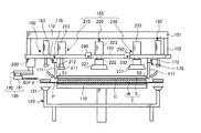
次に、剥離ステーション15に設置される剥離装置の構成および剥離装置を用いて行われる重合基板Tの剥離動作について説明する。図3Aは、剥離装置の構成を示す模式側面図であり、図3Bは、図3Aに示す剥離装置の構成を部分的に拡大して示す部分拡大模式側面図である。
<2. Configuration of peeling apparatus>
Next, the structure of the peeling apparatus installed in the peeling
図3Aに示すように、剥離装置5は処理部100を備える。処理部100の側面には、搬入出口(図示せず)が形成され、この搬入出口を介して、重合基板Tの処理部100への搬入や、剥離後の被処理基板Wおよび支持基板Sの処理部100からの搬出が行われる。搬入出口には、たとえば開閉シャッタが設けられ、この開閉シャッタによって処理部100と他の領域とが仕切られ、パーティクルの進入が防止される。なお、搬入出口は、第1搬送領域12に隣接する側面と受渡ステーション21に隣接する側面とにそれぞれ設けられる。
As illustrated in FIG. 3A, the
剥離装置5は、第1保持部110と、フレーム保持部120と、下側ベース部130と、回転昇降機構140と、第2保持部150と、上側ベース部160と、位置決め部170と、押し下げ部180と、剥離誘引部190と、位置調整部200とを備える。これらは処理部100の内部に配置される。
The
第1保持部110は、重合基板Tのうち被処理基板Wを下方から保持し、第2保持部150は、重合基板Tのうち支持基板Sを上方から保持する。そして、第2保持部150は、保持した支持基板Sを被処理基板Wの板面から離す方向へ移動させる。これにより、剥離装置5は、重合基板Tを支持基板Sと被処理基板Wとに剥離する。以下、各構成要素について具体的に説明する。
The
第1保持部110は、重合基板Tを構成する被処理基板WをダイシングテープPを介して吸着保持する。
The
第1保持部110は、円盤状の本体部111と、本体部111を支持する支柱部材112とを備える。支柱部材112は、下側ベース部130に支持される。
The
本体部111は、たとえばアルミニウムなどの金属部材で構成される。かかる本体部111の上面には、吸着面111aが設けられる。吸着面111aは、重合基板Tと略同径であり、重合基板Tの下面、すなわち、被処理基板Wの非接合面Wnと当接する。この吸着面111aは、たとえば炭化ケイ素等の多孔質体や多孔質セラミックで形成される。
The
本体部111の内部には、吸着面111aを介して外部と連通する吸引空間111bが形成される。吸引空間111bは、吸気管113を介して真空ポンプなどの吸気装置114と接続される。
Inside the
かかる第1保持部110は、吸気装置114の吸気によって発生する負圧を利用し、被処理基板Wの非接合面WnをダイシングテープPを介して吸着面111aに吸着させる。これにより、第1保持部110は被処理基板Wを保持する。なお、ここでは、第1保持部110がポーラスチャックである場合の例を示したが、第1保持部は、たとえば静電チャック等であってもよい。
The
第1保持部110の外方には、ダイシングフレームFを下方から保持するフレーム保持部120が配置される。かかるフレーム保持部120は、ダイシングフレームFを吸着保持する複数の吸着パッド121と、吸着パッド121を支持する支持部材122とを備える。
A
吸着パッド121は、ゴムなどの弾性部材によって形成され、たとえば図2Aに示すダイシングフレームFの前後左右の4箇所に対応する位置にそれぞれ設けられる。なお、上記では、吸着パッド121を4箇所に設けるようにしたが、これは例示であって限定されるものではなく、たとえば3箇所以下または5箇所以上であってもよい。
The
この吸着パッド121には、吸気口(図示せず)が形成され、真空ポンプなどの吸気装置125が支持部材122および吸気管124を介して上記の吸気口に接続される。また、吸着パッド121の吸気口は、第1保持部110の吸着面111aよりも鉛直方向において下側に位置される。
The
支柱部材122は、下側ベース部130に支持される。このように構成されたフレーム保持部120は、吸気装置125の吸気によって発生する負圧を利用し、ダイシングフレームFを吸着する。これにより、フレーム保持部120は、ダイシングフレームFを保持する。
The
下側ベース部130は、第1保持部110およびフレーム保持部120の下方に配置され、第1保持部110およびフレーム保持部120を支持する。下側ベース部130は、処理部100の床面に固定された回転昇降機構140によって支持される。
The
回転昇降機構140は、下側ベース部130を鉛直軸回りに回転させる。これにより、下側ベース部130に支持された第1保持部110およびフレーム保持部120が一体的に回転する。また、回転昇降機構140は、下側ベース部130を鉛直方向に移動させる。これにより、下側ベース部130に支持された第1保持部110およびフレーム保持部120が一体的に昇降する。
The
第1保持部110の上方には、第2保持部150が対向配置される。第2保持部150は、複数の吸着移動部を備える。具体的には、第1の実施形態に係る第2保持部150は、第1吸着移動部210と、第2吸着移動部220と、第3吸着移動部230とを備える。第1〜第3吸着移動部210,220,230は、上側ベース部160に支持される。上側ベース部160は、処理部100の天井部に取り付けられた固定部材101に支柱102を介して支持される。
Above the
第1吸着移動部210は、支持基板Sの一端S1側の周縁部を吸着保持する。また、第2吸着移動部220は、支持基板Sの周縁部よりも支持基板Sの中央部寄りの領域を吸着保持する。なお、第2吸着移動部220は、後述するように、X軸方向に複数、たとえば2つ並べて配置されるが、図3A,3Bでは紙面奥側の第2吸着移動部220の図示を省略した。
The first
また、第3吸着移動部230は、支持基板Sの他端S2側の周縁部を吸着保持する。そして、第1〜第3吸着移動部210,220,230は、吸着保持した領域をそれぞれ独立に被処理基板Wの板面から離す方向へ移動させる。
The third
第1吸着移動部210は、吸着パッド211と、支柱部材212と、移動機構213とを備える。また、第2吸着移動部220は、吸着パッド221と、支柱部材222と、移動機構223とを備える。同様に、第3吸着移動部230も、吸着パッド231と、支柱部材232と、移動機構233とを備える。
The first
吸着パッド211,221,231は、ゴムなどの弾性部材によって形成される。各吸着パッド211,221,231には、吸気口(図示せず)が形成されており、それぞれの吸気口には、吸気管214,224,234を介して真空ポンプなどの吸気装置215,225,235が接続される。
The
支柱部材212,222,232は、先端部において吸着パッド211,221,231を支持する。支柱部材212,222,232の基端部は、移動機構213,223,233によって支持される。移動機構213,223,233は、上側ベース部160の上部に固定されており、支柱部材212,222,232を鉛直方向に移動させる。
The
第1〜第3吸着移動部210,220,230は、吸気装置215,225,235の吸気によって発生する負圧を利用して支持基板Sを吸着する。これにより、第1〜第3吸着移動部210,220,230は、支持基板Sを保持する。
The first to third
また、第1〜第3吸着移動部210,220,230は、支持基板Sを保持した状態で、それぞれ移動機構213,223,233によって支柱部材212,222,232および吸着パッド211,221,231を鉛直方向に沿って移動させる。これにより、支持基板Sを鉛直方向に沿って移動させる。
The first to third
剥離装置5は、まず、移動機構213を動作させ、次いで、移動機構223を動作させて、最後に、移動機構233を動作させる。すなわち、剥離装置5は、支持基板Sを一端S1側の周縁部から先に引っ張り、次いで中央部を引っ張り、最後に他端S2側の周縁部を引っ張る。これにより、剥離装置5は、支持基板Sを、その一端S1から他端S2へ向けて被処理基板Wから徐々に、かつ連続的に剥離させる。この動作の具体的内容については、後述する。
The
第1保持部110の上方には、位置決め部170が配置される。位置決め部170は、第1搬送装置31によって剥離ステーション15へ搬送され、第1保持部110に載置された重合基板Tを規定の位置(たとえば吸着面111aと一致する位置)に位置決めする、換言すればセンタリングする。
A
位置決め部170は、たとえば図2Aに示す重合基板Tの外周の前後左右の4箇所に対応する位置にそれぞれ設けられる。なお、位置決め部170が設置される場所は、上記の4箇所に限定されるものではなく、たとえば重合基板Tの外周の前後または左右の2箇所、重合基板Tの中央部を中心として相互に120度の間隔をおいた3箇所、または5箇所以上に設置してもよい。
The positioning
位置決め部170は、図3Bによく示すように、アーム部171と、回転移動機構172とを備える。アーム部171は、長尺状の部材であり、基端部が回転移動機構172に回転可能に接続される。また、アーム部171の長手方向の長さは、たとえば、回転移動機構172によって先端部が鉛直下向きになるまで回転移動させられたときにその先端部が重合基板Tの側面に当接するような値に設定される。
The
回転移動機構172は、たとえば上側ベース部160の下部に固定され、アーム部171を基端側を中心に回転移動させる。各位置決め部170のアーム部171がそれぞれ回転移動機構172によって回転移動させられると、図3Bに想像線で示す如く、アーム部171の先端部が重合基板Tの側面に当接する。これにより、重合基板Tは、規定の位置に位置決めされる。このように、位置決め部170を備えることにより、仮に、重合基板Tが規定の位置からずれた状態で第1保持部110に載置された場合であっても、かかる重合基板Tを第1保持部110の正しい位置、詳しくはたとえば吸着面111aと一致する位置に移動させて修正することができる。
The
フレーム保持部120の各吸着パッド121の上方にはそれぞれ、押し下げ部180が配置される。すなわち、押し下げ部180は、各吸着パッド121に対応する位置に配置され、具体的にたとえば図2Aに示すダイシングフレームFの前後左右の4箇所に対応する位置にそれぞれ配置される。なお、上記では、押し下げ部180を、吸着パッド121と同じ4箇所に設けるようにしたが、これは例示であって、吸着パッド121の数に応じて変更してもよい。
A push-down
上記した押し下げ部180は、ダイシングフレームFを鉛直下向きに押し下げて吸着パッド121に吸着させる。具体的には、吸着パッド121の吸気口は、上記したように、第1保持部110の吸着面111aよりも鉛直方向において下側に位置される。そのため、第1搬送装置31によって剥離ステーション15へ搬送された重合基板Tが第1保持部110の吸着面111aに載置された状態のとき、ダイシングフレームFと吸着パッド121との間には、吸着パッド121が下がっている分だけ間隙が生じることとなる。そこで、押し下げ部180でダイシングフレームFを吸着パッド121側へ押し下げ、吸着パッド121に吸着させるようにする。
The above-described push-down
具体的に押し下げ部180は、図3Bによく示すように、押圧パッド181と、支柱部材182と、移動機構183とを備える。
Specifically, the push-down
押圧パッド181は、ゴムなどの弾性部材によって形成される。支柱部材182は、先端部に押圧パッド181が接続される。支柱部材182の基端部は、移動機構183によって支持される。移動機構183は、上側ベース部160の上部に固定されており、支柱部材182を鉛直方向に移動させる。
The
押し下げ部180は、移動機構183によって支柱部材182および押圧パッド181を鉛直方向に沿って移動させる。したがって、たとえば、移動機構183によって支柱部材182および押圧パッド181が鉛直下向きに移動させられると、押圧パッド181はダイシングフレームFに当接し、図3Bに想像線で示す如く、ダイシングフレームFを押圧して移動させる。それによって、ダイシングフレームFは鉛直下向きへ移動し、吸着パッド121に吸着保持される。
The push-down
これにより、重合基板Tの側面側には、後述する剥離誘引部190が侵入可能な空間が形成されることとなる。それによって剥離誘引部190の鋭利部材(後述)を重合基板Tの側面、正確には支持基板Sの接着剤G寄りの側面に容易に近づけて当接させることができる。
As a result, on the side surface side of the superposed substrate T, a space into which a later-described
図3Aに示すように、第2保持部150の外方には、剥離誘引部190が配置される。剥離誘引部190は、支持基板Sが被処理基板Wから剥離するきっかけとなる部位を重合基板Tにおける一端S1側の側面に形成する。
As illustrated in FIG. 3A, a peeling
剥離誘引部190は、鋭利部材191と、移動機構192とを備える。鋭利部材191は、たとえば刃物であり、先端が重合基板Tへ向けて突出するように移動機構192に支持される。なお、鋭利部材191は、たとえばカミソリ刃やローラ刃あるいは超音波カッター等を用いてもよい。
The peeling
移動機構192は、Y軸方向に延在するレールに沿って鋭利部材191を移動させる。剥離装置5は、移動機構192を用いて鋭利部材191を移動させることにより、支持基板Sの接着剤G寄りの側面に鋭利部材191を当接させる。これにより、剥離装置5は、支持基板Sが被処理基板Wから剥離するきっかけとなる部位(以下、「剥離開始部位」と記載する)を重合基板Tにおける一端S1側の側面に形成する。
The moving
また、移動機構192は、位置調整部200によって上方から支持される。位置調整部200は、たとえば上側ベース部160の下部に固定され、移動機構192を鉛直方向に沿って移動させる。これにより、鋭利部材191の高さ位置、すなわち、重合基板Tの側面への当接位置を調整することができる。
The moving
ここで、剥離誘引部190を用いて行われる剥離誘引処理の内容について図4A〜図4Cを参照して具体的に説明する。図4A〜図4Cは、剥離誘引処理の動作説明図である。
Here, the content of the peeling attraction process performed using the
なお、この剥離誘引処理は、重合基板Tのうちの被処理基板Wが第1保持部110(図3A参照)によって保持され、ダイシングフレームFがフレーム保持部120によって保持された後、かつ、支持基板Sが第2保持部150によって保持される前に行われる。すなわち、剥離誘引処理は、支持基板Sがフリーな状態で行われる。また、剥離装置5は、制御装置40の制御に基づき、図4A〜図4Cに示す剥離誘引処理を行う。
In this peeling attraction process, the substrate W to be processed among the superposed substrates T is held by the first holding unit 110 (see FIG. 3A), the dicing frame F is held by the
剥離装置5は、位置調整部200を用いて鋭利部材191の高さ位置を調整した後、移動機構192(図3A参照)を用いて鋭利部材191を重合基板Tの側面へ向けて移動させる。具体的には、図4Aに示すように、重合基板Tにおける一端S1側の側面のうち、支持基板Sの接着剤G寄りの側面に向けて鋭利部材191を略水平に移動させる。
The
「支持基板Sの接着剤G寄りの側面」とは、支持基板Sの側面のうち、支持基板Sの厚みの半分の位置h1よりも接合面Sj寄りの側面である。すなわち、支持基板Sの側面は略円弧状に形成されており、「支持基板Sの接着剤G寄りの側面」は、鋭利部材191と接合面Sjとのなす角度を0度とした場合における鋭利部材191とのなす角度θが0度以上90度未満の側面である。
The “side surface of the support substrate S near the adhesive G” is the side surface of the support substrate S that is closer to the bonding surface Sj than the position h1 that is half the thickness of the support substrate S. That is, the side surface of the support substrate S is formed in a substantially arc shape, and the “side surface of the support substrate S near the adhesive G” is sharp when the angle between the
剥離装置5は、まず、鋭利部材191を予め決められた位置まで前進させる(予備前進)。その後、剥離装置5は、鋭利部材191をさらに前進させて鋭利部材191を支持基板Sの接着剤G寄りの側面に当接させる。なお、剥離誘引部190には、たとえばロードセル(図示せず)が設けられており、剥離装置5は、かかるロードセルを用いて鋭利部材191にかかる負荷を検出することによって、鋭利部材191が支持基板Sに当接したことを検出する。
The
上述したように支持基板Sの側面は略円弧状に形成されている。したがって、鋭利部材191が支持基板Sの接着剤G寄りの側面に当接することにより、支持基板Sには、上方向きの力が加わることとなる。
As described above, the side surface of the support substrate S is formed in a substantially arc shape. Therefore, when the
つづいて、図4Bに示すように、剥離装置5は、鋭利部材191をさらに前進させる。これにより、支持基板Sは、側面の湾曲に沿って上方へ押し上げられる。この結果、支持基板Sの一部が接着剤Gから剥離して剥離開始部位Mが形成される。
Subsequently, as shown in FIG. 4B, the
なお、支持基板Sは第2保持部150によって保持されておらずフリーな状態であるため、支持基板Sの上方への移動が阻害されることがない。本処理において、鋭利部材191を前進させる距離a1は、たとえば2mm程度である。
Since the support substrate S is not held by the
また、剥離装置5においては、上記した処理による支持基板Sの剥離状態を確認する確認装置、具体的には剥離開始部位Mが形成されたことを確認する確認装置(図示せず)を設けるように構成してもよい。具体的に確認装置は、たとえば支持基板Sの上方に設置されたIR (Infrared。赤外線)カメラ(図示せず)である。
Moreover, in the
詳しくは、赤外線は、支持基板Sにおいて被処理基板Wから剥離した部位と剥離していない部位とでその反射率が変化する。そこで、先ずIRカメラで支持基板Sを撮像することで、支持基板Sにおける赤外線の反射率の違い等が示された画像データを取得する。そして、画像データは制御装置40へ送信され、制御装置40では、その画像データに基づき、支持基板Sにおいて被処理基板Wから剥離した部位、すなわち剥離開始部位Mを検出することができる。
Specifically, the reflectance of infrared rays varies depending on whether the support substrate S is peeled off from the substrate W to be processed or not. Therefore, first, the support substrate S is imaged by the IR camera, and image data showing a difference in the reflectance of infrared rays on the support substrate S is acquired. Then, the image data is transmitted to the
制御装置40において剥離開始部位Mが検出された場合、剥離装置5は後述する次の処理へ移行する。一方、制御装置40において剥離開始部位Mが検出されない場合、剥離装置5は、たとえば鋭利部材191をさらに前進させる、または鋭利部材191を一旦後退させて支持基板Sから離し、その後図4A,4Bで示した動作を再度実行するなどして、剥離開始部位Mを形成するようにする。このように、支持基板Sの剥離状態を確認する確認装置を設け、剥離状態に応じて剥離装置5を動作させることで、剥離開始部位Mを確実に形成することができる。
When the peeling start site M is detected in the
剥離開始部位Mが形成されると、つづいて、図4Cに示すように、剥離装置5は、回転昇降機構140(図3A参照)を用いて第1保持部110を降下させつつ、鋭利部材191をさらに前進させる。これにより、被処理基板Wおよび接着剤Gには下方向きの力が加わり、鋭利部材191によって支持された支持基板Sには上方向きの力が加わる。これにより、剥離開始部位Mが拡大する。
When the peeling start site M is formed, as shown in FIG. 4C, the
なお、本処理において、鋭利部材191を前進させる距離a2は、たとえば1mm程度である。
In this process, the distance a2 for moving the
このように、剥離装置5は、支持基板Sの接着剤G寄りの側面に鋭利部材191を突き当てることにより、支持基板Sが被処理基板Wから剥がれるきっかけとなる剥離開始部位Mを重合基板Tの側面に形成することができる。
In this way, the
支持基板Sは、接着剤Gの約5〜15倍程度の厚みを有する。したがって、鋭利部材191を接着剤Gに当接させて剥離開始部位を形成する場合と比較して、鋭利部材191の鉛直方向の位置制御が容易である。
The support substrate S has a thickness of about 5 to 15 times that of the adhesive G. Therefore, compared with the case where the sharpening
また、支持基板Sの接着剤G寄りの側面に鋭利部材191を当接させることによって、支持基板Sを被処理基板Wから引き剥がす方向の力(すなわち、上向きの力)を支持基板Sに加えることができる。しかも、支持基板Sの最外縁部に近い部位を持ち上げるため、支持基板Sを被処理基板Wから引き剥がす方向の力を支持基板Sに対して効率的に加えることができる。
Further, the
また、鋭利部材191を接着剤Gに突き当てる場合と比較して、鋭利部材191が被処理基板Wに接触する可能性を低下させることができる。
Further, compared with the case where the
なお、「支持基板Sの接着剤G寄りの側面」は、より好ましくは、図4Aに示すように、支持基板Sの接合面Sjから支持基板Sの厚みの1/4の位置h2までの側面、すなわち、鋭利部材191とのなす角度θが0度以上45度以下の側面であるのが好ましい。鋭利部材191とのなす角度θが小さいほど、支持基板Sを持ち上げる力を大きくすることができるためである。
The “side surface of the support substrate S near the adhesive G” is more preferably the side surface from the bonding surface Sj of the support substrate S to the position h2 that is ¼ of the thickness of the support substrate S, as shown in FIG. 4A. In other words, it is preferable that the angle θ formed with the
また、支持基板Sと接着剤Gとの接着力が比較的弱い場合には、図4Aに示すように、鋭利部材191を支持基板Sの接着剤G寄りの側面に当接させるだけで剥離開始部位Mを形成することができる。このような場合、剥離装置5は、図4Bおよび図4Cに示す動作を省略することができる。
Further, when the adhesive force between the support substrate S and the adhesive G is relatively weak, as shown in FIG. 4A, the peeling is started simply by bringing the
また、支持基板Sと接着剤Gとの接着力が比較的強い場合には、剥離装置5は、たとえば図4Cに示す状態からさらに回転昇降機構140を回転させ、第1保持部110およびフレーム保持部120を鉛直軸回りにたとえば360度回転させるようにしてもよい。これにより、剥離開始部位Mが支持基板Sの接合面Sjの全周に亘って形成されることとなり、支持基板Sを被処理基板Wから剥がし易くすることができる。
When the adhesive force between the support substrate S and the adhesive G is relatively strong, the
次に、第1〜第3吸着移動部210,220,230の配置等について図5を参照して説明する。図5は、支持基板S、第1吸着移動部210が備える吸着パッド211、第2吸着移動部220が備える吸着パッド221、および第3吸着移動部230が備える吸着パッド231の位置関係を示す模式平面図である。
Next, arrangement | positioning etc. of the 1st-3rd adsorption | suction moving part 210,220,230 are demonstrated with reference to FIG. FIG. 5 is a schematic diagram showing the positional relationship among the support substrate S, the
図5に示すように、第1吸着移動部210が備える吸着パッド211は、剥離開始部位Mに対応する支持基板Sの一端S1側の周縁部を吸着する。また、第2吸着移動部220は、支持基板Sの一端S1から他端S2へ向かう方向(すなわちY軸方向)と交差する方向(すなわちX軸方向)に複数並べて配置される、具体的にたとえば2つ並列に配置される。それら第2吸着移動部220が備える吸着パッド221は、支持基板Sの一端S1と他端S2との間の領域、詳しくは一端S1側の周縁部よりも支持基板Sの中央寄りの領域を吸着する。また、第3吸着移動部230が備える吸着パッド231は、支持基板Sの他端S2側の周縁部を吸着する。
As shown in FIG. 5, the
吸着パッド221,231は、吸着面積が略同じとなるように形成される一方、吸着パッド211は、吸着パッド221,231よりも吸着面積が小さく形成される。これは、吸着パッド211を小さく形成することで、剥離開始部位Mが形成された部分に対応する支持基板Sの周縁部のみを吸着して引き上げることができるためである。これにより、剥離開始部位Mが形成されていない周縁部まで吸着して引き上げることで剥離力が低下することを防止することができる。
The
なお、吸着パッド211は、たとえば鋭利部材191のX軸方向における刃幅よりも小さく形成されることが好ましい。これにより、剥離開始部位Mが形成されていない支持基板Sの周縁部を吸着パッド211が吸着してしまうことを確実に防止することができる。言い換えれば、剥離開始部位Mが形成された支持基板Sの周縁部のみを正確に吸着することができる。なお、吸着パッド221,231は、鋭利部材191のX軸方向における刃幅よりも大きく形成される。
The
図5に示すように、吸着パッド211,221,231は、鋭利部材191の移動方向(Y軸方向)に沿うようにして配置される。剥離装置5は、吸着パッド211を吸着パッド221,231よりも先に引き上げ、その後吸着パッド221を吸着パッド231よりも先に引き上げる、すなわち、支持基板Sを一端S1側の周縁部から先に引っ張り、吸着パッド221,231の順で引っ張る。これにより、剥離装置5は、支持基板Sを、その一端S1から中央部付近を経て他端S2へ向けて被処理基板Wから徐々に、かつ連続的に剥離させる。
As shown in FIG. 5, the
ところで、支持基板Sは、上記したように、一端S1から他端S2へ向けて被処理基板Wから徐々に剥離させられる。しかしながら、たとえば支持基板Sの第2吸着移動部220によって吸着される領域が未だ被処理基板Wから剥離していない状態のときに、第2吸着移動部220で支持基板Sを吸着して引き上げる方向へ移動させると、第2吸着移動部220に過度な負荷が作用し、たとえば吸着パッド221が支持基板Sから外れてしまうおそれがある。また、支持基板Sの第3吸着移動部230によって吸着される領域が被処理基板Wから剥離していない場合の第3吸着移動部230についても同様である。
By the way, as described above, the support substrate S is gradually peeled from the substrate W to be processed from one end S1 to the other end S2. However, for example, when the region sucked by the second
そこで、第1の実施形態に係る剥離装置5においては、支持基板Sの被処理基板Wからの剥離状態を検知する状態検知部を備え、制御装置40が、状態検知部によって検知された剥離状態に基づき、支持基板Sが支持基板Sの一端S1から他端S2へ向けて被処理基板Wから徐々に剥離するように、第2、第3吸着移動部220,230の動作タイミングを制御するようにした。
Therefore, the
これにより、第2、第3吸着移動部220,230で支持基板Sを吸着し、支持基板Sを被処理基板Wの板面から離す方向へ移動させる動作を適切なタイミングで行うことができ、よって第2、第3吸着移動部220,230に過度な負荷が作用するのを防止することができる。
As a result, the support substrate S is sucked by the second and third
ここで、状態検知部について詳しく説明する。第1の実施形態に係る状態検知部は、図3Aに示すように、たとえば上側ベース部160に設けられ、所定の測定基準位置から支持基板Sまでの距離d1,d2を計測する計測部240,250である。計測部240,250としては、たとえばレーザ変位計を用いることができる。なお、図5においては、支持基板Sにおいて計測部240,250が配置される位置に対応する部分を破線で示した。
Here, the state detection unit will be described in detail. As shown in FIG. 3A, the state detection unit according to the first embodiment is provided in, for example, the
また、上記では、計測部240,250としてレーザ変位計を例に挙げたが、これに限定されるものではなく、たとえば静電容量センサなど所定の測定基準位置から支持基板Sまでの距離d1,d2を計測することができればどのようなものであってもよい。
In the above description, the laser displacement meter is taken as an example of the measuring
図3Bおよび図5に示すように、計測部240は、第1吸着移動部210と第2吸着移動部220との間のうち、第2吸着移動部220寄りの位置に配置される。具体的には、計測部240は、支持基板Sにおいて第2吸着移動部220の吸着パッド221で吸着される領域の上方の位置に近接して設けられる。
As shown in FIG. 3B and FIG. 5, the measuring
計測部250は、図3Aおよび図5に示す如く、第2吸着移動部220と第3吸着移動部230との間のうち、第3吸着移動部230寄りの位置に配置される。具体的には、計測部250は、支持基板Sにおいて第3吸着移動部230の吸着パッド231で吸着される領域の上方の位置に近接して設けられる。上記した計測部240,250の計測結果は、制御装置40へ送信される。
As shown in FIGS. 3A and 5, the measuring
制御装置40は、計測部240,250の計測結果に基づき、支持基板Sの第2吸着移動部220または第3吸着移動部230によって吸着される領域が被処理基板Wから剥離されたか否かを判定する。
Based on the measurement results of the
具体的には、制御装置40は、第1吸着移動部210で支持基板Sを被処理基板Wから離れる方向に移動させた後、計測部240によって計測された距離d1がしきい値D1以上の場合、支持基板Sの第2吸着移動部220によって吸着される領域は未だ被処理基板Wから剥離されていないと判定する。そして、制御装置40は、支持基板Sの剥離が進んで距離d1がしきい値D1未満となった場合、一端S1側の周縁部と中央部寄りの領域との間の所定位置まで支持基板Sが剥離されたと判定する。正確には、制御装置40は、支持基板Sの第2吸着移動部220によって吸着される領域が被処理基板Wから剥離されたと判定する。しきい値D1は、支持基板Sの第2吸着移動部220によって吸着される領域が被処理基板Wから剥離した際の距離d1に相当する。
Specifically, after the
そして、制御装置40は、上記した領域が被処理基板Wから剥離されたと判定した場合、その領域を吸着する第2吸着移動部220を動作させて吸着保持し、支持基板Sを被処理基板Wの板面から離す方向へ移動させるようにする。これにより、第2吸着移動部220に過度な負荷が作用するのを防止することができる。
When the
同様に、制御装置40は、第2吸着移動部220で支持基板Sを被処理基板Wから離れる方向に移動させた後、計測部250によって計測された距離d2がしきい値D2以上の場合、支持基板Sの第3吸着移動部230によって吸着される領域は未だ被処理基板Wから剥離されていないと判定する。そして、制御装置40は、支持基板Sの剥離が進んで距離d2がしきい値D2未満となった場合、中央部寄りの領域と他端S2側の周縁部との間の所定位置まで支持基板Sが剥離されたと判定する。正確には、制御装置40は、支持基板Sの第3吸着移動部230によって吸着される領域が被処理基板Wから剥離されたと判定する。しきい値D2は、支持基板Sの第3吸着移動部230によって吸着される領域が被処理基板Wから剥離した際の距離d2に相当する。
Similarly, the
そして、制御装置40は、第3吸着移動部230によって吸着される領域が被処理基板Wから剥離されたと判定した場合、その領域を吸着する第3吸着移動部230を動作させて、支持基板Sを被処理基板Wの板面から離す方向へ移動させるようにする。これにより、第3吸着移動部230に過度な負荷が作用するのを防止することができる。
When the
上記した剥離動作の具体的な内容について図6および図7A〜図7Iを参照して説明する。図6は、剥離処理の処理手順を示すフローチャートである。また、図7A〜図7Iは、剥離装置5による剥離動作の説明図である。なお、剥離装置5は、制御装置40の制御に基づき、図6に示す各処理手順を実行する。
Specific contents of the above-described peeling operation will be described with reference to FIGS. 6 and 7A to 7I. FIG. 6 is a flowchart showing a processing procedure of the peeling process. 7A to 7I are explanatory diagrams of the peeling operation by the
まず、剥離装置5は、第1搬送装置31によって剥離ステーション15へ搬入され、第1保持部110に載置された重合基板Tを、位置決め部170でセンタリングする(ステップS101)。これにより、重合基板Tは第1保持部110の規定の位置に位置決めされる(図7A参照)。
First, the
次いで、剥離装置5は、第1保持部110を用い、被処理基板WをダイシングテープPを介して吸着保持する(ステップS102)。これにより、重合基板Tは、第1保持部110によって被処理基板Wが保持される。
Next, the
つづいて、剥離装置5は、押し下げ部180を用いてダイシングフレームFを鉛直下向きに押し下げ、ダイシングフレームFをフレーム保持部120で吸着保持する(ステップS103)。これにより、重合基板Tの側面側には、剥離誘引部190が侵入可能な空間が形成される(図7B参照)。
Subsequently, the
その後、剥離装置5は、剥離誘引部190を上記した空間に侵入させつつ、図4A〜図4Cを参照して説明した剥離誘引処理を行う(ステップS104)。これにより、重合基板Tの一端S1側の側面に剥離開始部位M(図4B参照)が形成される(図7C参照)。
Thereafter, the
なお、前述したように、たとえば支持基板Sと接着剤Gとの接着力が比較的強い場合には、剥離装置5は、S104の処理においてさらに回転昇降機構140を回転させ、第1保持部110およびフレーム保持部120を鉛直軸回りにたとえば360度回転させるようにしてもよい。これにより、剥離開始部位Mが支持基板Sの接合面Sjの全周に亘って形成されることとなり、支持基板Sを被処理基板Wから剥がし易くすることができる。
As described above, for example, when the adhesive force between the support substrate S and the adhesive G is relatively strong, the
つづいて、剥離装置5は、第1〜第3吸着移動部210,220,230の吸着パッド211,221,231を、支持基板Sの近傍まで降下させる(ステップS105。図7D参照)。
Subsequently, the
その後、剥離装置5は、第1吸着移動部210を用いて支持基板Sの非接合面Snを吸着保持する(ステップS106)。上述したように、第1吸着移動部210は、剥離開始部位Mに対応する支持基板Sの一端S1側の周縁部を吸着保持する。
Thereafter, the
つづいて、剥離装置5は、第1吸着移動部210の吸着パッド211を上昇させる(ステップS107)。すなわち、剥離装置5は、剥離開始部Mに対応する支持基板Sの一端S1側の周縁部を引っ張る。これにより、支持基板Sが、その周縁部から中心部へ向けて被処理基板Wから連続的に剥離し始める(図7E参照)。
Subsequently, the
そして、剥離装置5は、計測部240によって計測された、所定の測定基準位置から支持基板Sまでの距離d1がしきい値D1未満か否かを判定する(ステップS108)。距離d1がしきい値D1以上の場合(ステップS108,No)、支持基板Sの第2吸着移動部220によって吸着される領域は未だ被処理基板Wから剥離されていないと判定し、ステップS108の処理を繰り返す。
Then, the
他方、距離d1がしきい値D1未満の場合(ステップS108,Yes)、支持基板Sの第2吸着移動部220によって吸着される領域が被処理基板Wから剥離されたと判定する。そして、剥離装置5は、第2吸着移動部220を下降させ、第2吸着移動部220を用いて支持基板Sの非接合面Snを吸着保持する(ステップS109)。上述したように、第2吸着移動部220は、支持基板Sの一端S1側の周縁部よりも中央部寄りの領域を吸着保持する(図7F参照)。
On the other hand, when the distance d1 is less than the threshold value D1 (step S108, Yes), it is determined that the region sucked by the second
その後、剥離装置5は、第2吸着移動部220の吸着パッド221を上昇させる(ステップS110)。すなわち、剥離装置5は、支持基板Sの一端S1側の周縁部を引っ張りつつ、支持基板Sの中央部付近をさらに引っ張る(図7G参照)。
Thereafter, the
つづいて、剥離装置5は、計測部250によって計測された、所定の測定基準位置から支持基板Sまでの距離d2がしきい値D2未満か否かを判定する(ステップS111)。距離d2がしきい値D2以上の場合(ステップS111,No)、支持基板Sの第3吸着移動部230によって吸着される領域は未だ被処理基板Wから剥離されていないと判定し、ステップS111の処理を繰り返す。
Subsequently, the
他方、距離d2がしきい値D2未満の場合(ステップS111,Yes)、支持基板Sの第3吸着移動部230によって吸着される領域が被処理基板Wから剥離されたと判定する。そして、剥離装置5は、第3吸着移動部230を下降させ、第3吸着移動部230を用いて支持基板Sの非接合面Snを吸着保持する(ステップS112)。上述したように、第3吸着移動部230は、支持基板Sの他端S2側の周縁部を吸着保持する(図7H参照)。
On the other hand, when the distance d2 is less than the threshold value D2 (step S111, Yes), it is determined that the region sucked by the third
その後、剥離装置5は、第3吸着移動部230の吸着パッド231を上昇させる(ステップS113)。すなわち、剥離装置5は、支持基板Sの一端S1側の周縁部および支持基板Sの中央部付近を引っ張りつつ、支持基板Sの他端S2側の周縁部をさらに引っ張る。これにより、支持基板Sが被処理基板Wから剥離する。
Thereafter, the
その後、剥離装置5は、第2、第3吸着移動部220,230のみを上昇させ、あるいは、第1、第2吸着移動部210,220のみを降下させるなどして支持基板Sを水平にし、鋭利部材191を後退させて、剥離処理を終了する(図7I参照)。
Thereafter, the
このように、第1の実施形態に係る剥離装置5では、第1吸着移動部210が支持基板Sの周縁部を被処理基板Wの板面から離す方向へ移動させた後で、第2、第3吸着移動部220,230が支持基板Sの中央部や他端S2を被処理基板Wの板面から離す方向へ移動させることとした。
Thus, in the
これにより、支持基板Sに対して大きな負荷をかけることなく、重合基板Tを支持基板Sと被処理基板Wとに剥離することができる。 Thereby, the superposition | polymerization board | substrate T can be peeled into the support substrate S and the to-be-processed substrate W, without applying big load with respect to the support substrate S. FIG.
すなわち、たとえば特表2007−526628号公報に記載の技術のように、重合基板の一方の周縁部を支点とし他方の周縁部に引張力を加えることによって重合基板を剥離する場合、剥離が進むに連れて支持基板が大きく反ってしまうという問題がある。これに対し、剥離装置5によれば、支持基板Sの周縁部を吸着保持する第1吸着移動部210と、支持基板Sの中央部を吸着保持する第2吸着移動部220とを用いて剥離動作を行うことで、支持基板Sの変形を抑えつつ剥離を進めることができる。
That is, for example, as in the technique described in Japanese Patent Publication No. 2007-526628, when a superposed substrate is peeled off by applying a tensile force to one peripheral portion of the superposed substrate as a fulcrum, the peeling proceeds. As a result, there is a problem that the support substrate is greatly warped. On the other hand, according to the
また、第1の実施形態に係る剥離装置5においては、状態検知部によって検知された剥離状態に基づき、第2、第3吸着移動部220,230の動作タイミングを制御することとした。これにより、たとえば支持基板Sの第2吸着移動部220によって吸着される領域が未だ被処理基板Wから剥離していない状態のときに、第2吸着移動部220で支持基板Sを吸着して引き上げる方向へ移動させてしまうのを防止することができる。これによって第2吸着移動部220に過度な負荷が作用することはなく、たとえば吸着パッド221が支持基板Sから外れることもない。
Moreover, in the
なお、剥離装置5は、被処理基板Wと支持基板Sとが剥離した後、回転昇降機構140を用いて第1保持部110およびフレーム保持部120を回転させてもよい。これにより、仮に、支持基板Sと被処理基板Wとに跨って貼り付いた接着剤Gが存在する場合に、かかる接着剤Gをねじ切ることができる。
Note that the
また、剥離装置5は、支持基板Sの剥離時に移動機構213,223,233に作用する負荷を検出し、検出結果に応じて図6の剥離処理を途中で停止するようにしてもよい。具体的には、剥離装置5は、たとえば第1〜第3吸着移動部210,220,230にそれぞれロードセル(図示せず)を設け、支持基板Sを吸着して剥離させる際に移動機構213,223,233が支持基板Sから受ける負荷を検出する。そして、剥離装置5は、検出された移動機構213,223,233の負荷のうち、少なくともいずれかがしきい値を超えた場合、具体的には移動機構213,223,233に作用する負荷のいずれかが過度に増加した場合、図6の剥離処理を途中で停止する。これにより、第1〜第3吸着移動部210,220,230が支持基板Sを被処理基板Wから過度な力で剥離させることはなく、よってたとえば重合基板Tに割れなどが生じるのを防止することができる。
Further, the
剥離装置5が剥離処理を終えると、第3搬送装置33(図1参照)は、剥離後の支持基板Sを剥離装置5から受け取り、受け取った支持基板Sを第2洗浄ステーション22(図1参照)の第2洗浄装置へ載置する。
When the
ここで、剥離後の支持基板Sは、第1吸着移動部210および第2吸着移動部220によって非接合面Sn側が保持された状態となっており、第3搬送装置33は、支持基板Sの接合面Sj側を下方から非接触で保持する。このように、第2保持部150は、剥離後の支持基板Sを第3搬送装置33へ受け渡す受渡部としても機能する。第1の実施形態では、第2吸着移動部220が支持基板Sの中央部付近を吸着することとしたため、剥離後の支持基板Sを安定して保持しておくことができる。
Here, the support substrate S after being peeled is in a state in which the non-bonding surface Sn side is held by the first
また、第1搬送装置31(図1参照)は、剥離後の被処理基板Wを剥離装置5から搬出して、第1洗浄ステーション16へ搬送する。このとき、剥離後の被処理基板Wは、図7Iに示すように、洗浄すべき接合面Wjが上面に位置した状態で、第1保持部110に保持されている。このため、第1搬送装置31は、剥離後の被処理基板Wを剥離装置5から搬出した後、かかる被処理基板Wを反転させることなくそのまま第1洗浄ステーション16へ搬送することができる。
Further, the first transfer device 31 (see FIG. 1) carries the substrate to be processed W after peeling from the
このように、剥離装置5では、第1保持部110が被処理基板Wを下方から保持し、第2保持部150が重合基板Tのうち支持基板Sを上方から保持するため、剥離後の被処理基板Wを反転させる必要がなく、剥離処理を効率化させることができる。
As described above, in the
上述してきたように、第1の実施形態に係る剥離装置5は、第1保持部(保持部)110と、複数の吸着移動部210,220,230と、計測部(状態検知部)240,250と、制御装置(制御部)40とを備える。第1保持部110は、被処理基板W(第1基板の一例)と支持基板S(第2基板の一例)とが接合された重合基板Tのうち被処理基板Wを保持する。複数の吸着移動部210,220,230は、重合基板Tのうち支持基板Sを吸着し、支持基板Sを被処理基板Wの板面から離す方向へ移動させる。計測部240,250は、支持基板Sの被処理基板Wからの剥離状態を検知する。制御装置40は、計測部240,250によって検知された剥離状態に基づき、支持基板Sが支持基板Sの一端S1から他端S2へ向けて被処理基板Wから徐々に剥離するように、吸着移動部210,220,230の動作タイミングを制御する。
As described above, the
したがって、第1の実施形態に係る剥離装置5によれば、剥離処理の効率化を図ることができる。また、第1の実施形態に係る剥離装置5によれば、第2、第3吸着移動部220,230および支持基板Sに大きな負荷をかけることなく、重合基板Tを支持基板Sと被処理基板Wとに剥離することができる。さらに、重合基板Tを短時間で剥離することができる。
Therefore, according to the
また、第1の実施形態に係る剥離装置5では、剥離誘引部190が、鋭利部材191と、重合基板Tにおける一端S1側の側面のうち、支持基板Sにおける被処理基板Wと支持基板Sとの接合部分である接着剤G寄りの側面に向けて鋭利部材191を移動させる移動機構192とを備える。また、鋭利部材191が被処理基板Wに接触して被処理基板Wが傷つく可能性も低下させることができる。
Moreover, in the
ところで、状態検知部の構成は、第1の実施形態において示した構成に限定されない。たとえば、状態検知部は、図3Bに想像線で示すように、第1、第2吸着移動部210,220の移動量、正確には第1、第2吸着移動部210,220の吸着パッド211,221の移動量を検出する移動量検出部260,270であってもよい。移動量検出部260,270は、たとえばエンコーダである。すなわち、支持基板Sの剥離に伴って、第1、第2吸着移動部210,220の移動量が増加することを利用して、剥離状態を判定するようにした。
By the way, the structure of a state detection part is not limited to the structure shown in 1st Embodiment. For example, as indicated by an imaginary line in FIG. 3B, the state detection unit moves the first and second
この場合の制御装置40は、第1吸着移動部210で支持基板Sを被処理基板Wから離れる方向に移動させた後、移動量検出部260で検出された吸着パッド211の移動量が増加してしきい値以上になった場合、一端S1側の周縁部と中央部寄りの領域との間の所定位置まで支持基板Sが剥離されたと判定する。
In this case, the
同様に、制御装置40は、第2吸着移動部220で支持基板Sを被処理基板Wから離れる方向に移動させた後、移動量検出部270で検出された吸着パッド221の移動量が増加してしきい値以上になった場合、中央部寄りの領域と他端S2側の周縁部との間の所定位置まで支持基板Sが剥離されたと判定する。
Similarly, after the
また、状態検知部は、図3Bに想像線で示すように、支持基板Sを被処理基板Wの板面から離す方向へ移動させる際に第1、第2吸着移動部210,220が支持基板Sから受ける負荷を検出する負荷検出部280,290であってもよい。負荷検出部280,290は、たとえばロードセルである。すなわち、支持基板Sの剥離に伴って、第1、第2吸着移動部210,220に作用する負荷が減少することを利用して、剥離状態を判定するようにした。
In addition, as indicated by an imaginary line in FIG. 3B, the state detection unit moves the support substrate S in the direction away from the plate surface of the substrate W to be processed, so that the first and second
この場合の制御装置40は、第1吸着移動部210で支持基板Sを被処理基板Wから離れる方向に移動させた後、負荷検出部280で検出された負荷が減少してしきい値未満になった場合、一端S1側の周縁部と中央部寄りの領域との間の所定位置まで支持基板Sが剥離されたと判定する。
In this case, the
同様に、制御装置40は、第2吸着移動部220で支持基板Sを被処理基板Wから離れる方向に移動させた後、負荷検出部290で検出された負荷が減少してしきい値未満になった場合、中央部寄りの領域と他端S2側の周縁部との間の所定位置まで支持基板Sが剥離されたと判定する。
Similarly, after the
また、第2保持部の構成は、第1の実施形態において示した構成に限定されない。そこで、以下では、第2保持部の変形例について図8A〜図8Cを参照して説明する。図8A〜図8Cは、第2保持部の変形例を示す模式平面図である。 Further, the configuration of the second holding unit is not limited to the configuration shown in the first embodiment. Therefore, in the following, a modified example of the second holding unit will be described with reference to FIGS. 8A to 8C. 8A to 8C are schematic plan views illustrating modifications of the second holding unit.
上述した第1の実施形態では、第1吸着移動部が支持基板Sの一端S1側の周縁部を1箇所で吸着保持する場合の例を示したが、たとえば第1吸着移動部が周縁部を複数箇所で吸着保持するようにしてもよい。 In 1st Embodiment mentioned above, although the 1st adsorption | suction movement part showed the example in the case of adsorbing and hold | maintaining the peripheral part by the side of the one end S1 of the support substrate S in one place, for example, a 1st adsorption | suction movement part has a peripheral part. You may make it adsorb and hold in multiple places.
具体的には図8Aに示すように、第1吸着移動部210の吸着パッド211A,211B,211Cが支持基板Sの一端S1側の周縁部に沿って複数個(たとえば3個)配置される。このように、複数個の吸着パッド211A,211B,211Cを用いて支持基板Sを吸着保持することで、支持基板Sの一端S1側を被処理基板Wから確実に剥離させることができる。
Specifically, as shown in FIG. 8A, a plurality (for example, three) of
また、図8Aに示すように、第3吸着移動部を除去するようにしてもよい。これにより、第2保持部の構成を簡素化することができる。なお、図8Aにおいて、第3吸着移動部を除去する場合を示したが、これはあくまでも例示であって第3吸着移動部を除去しなくてもよい。 Further, as shown in FIG. 8A, the third suction moving unit may be removed. Thereby, the structure of a 2nd holding | maintenance part can be simplified. In addition, although the case where the 3rd adsorption | suction movement part was removed was shown in FIG. 8A, this is an illustration to the last and it is not necessary to remove a 3rd adsorption | suction movement part.
また、図8Aでは、吸着パッド211A,211B,211C,221の吸着面積が略同じとなるようにした。これにより、たとえば吸着パッドの部材を共通化することができる。なお、ここでは吸着パッド211A,211B,211C,221の吸着面積が略同じとなる例を示したが、これに限定されるものではなく、互いの吸着面積が異なるようにしてもよい。
In FIG. 8A, the
また、上述した第1の実施形態では、第2吸着移動部が支持基板Sの中央部付近を複数箇所(2箇所)で吸着保持する場合の例を示したが、第2吸着移動部が吸着保持する領域は、支持基板Sの中央部のみであってもよい。 In the first embodiment described above, an example in which the second suction moving unit holds and holds the vicinity of the central portion of the support substrate S at a plurality of locations (two locations) has been described. The area to be held may be only the central part of the support substrate S.
具体的には図8Bに示すように、吸着パッド221Aが支持基板Sの中心部に配置され、中心部を吸着することとしてもよい。これにより、第2保持部の構成を簡素化することができる。
Specifically, as illustrated in FIG. 8B, the
また、第2保持部は、複数の第2吸着移動部を一端S1から他端S2へ向かう方向(Y軸方向)と平行に直線状に並べ、さらに一端S1から他端S2へ向かうにつれて吸着保持される領域が徐々に大きくなるようにしてもよい。 In addition, the second holding unit arranges the plurality of second suction moving units in a straight line in parallel with the direction from the one end S1 to the other end S2 (Y-axis direction), and further holds the suction by holding from one end S1 to the other end S2. The area to be applied may be gradually increased.
たとえば、図8Cに示すように、第2保持部は、支持基板Sの中心部に配置される吸着パッド221Aと、吸着パッド221Aと吸着パッド211との間に配置される吸着パッド221Bとを備える。また、吸着パッド211,221B,221A,231Aは、一端S1から他端S2に向かうにつれて吸着面積が大きくなる。
For example, as illustrated in FIG. 8C, the second holding unit includes a
これにより、支持基板Sの剥離が進むにつれて、支持基板Sは吸着面積の大きい吸着パッドによって吸着保持されるため、支持基板Sを効率良く剥離できるとともに、剥離された支持基板Sを第2保持部で確実に保持することができる。なお、第2保持部の構成は、上記した例に限定されるものではなく、たとえば第3吸着移動部230を除去して剥離システム1の簡素化を図るようにしてもよい。
Thus, as the support substrate S is peeled off, the support substrate S is sucked and held by the suction pad having a large suction area, so that the support substrate S can be efficiently peeled off and the peeled support substrate S is held in the second holding unit. Can be securely held. Note that the configuration of the second holding unit is not limited to the above-described example. For example, the third
また、第1の実施形態に係る剥離装置5がさらに、支持基板Sの被処理基板Wとの接合面Sjの全てが被処理基板Wから剥がれて剥離が完了したことを検知する剥離完了検知部を備えるようにしてもよい。以下では、第1の実施形態に係る剥離装置5のさらなる変形例について説明する。
In addition, the
図9は、第1の実施形態に係る剥離装置5の変形例において、支持基板S、第1吸着移動部210の吸着パッド211、第2吸着移動部220の吸着パッド221、第3吸着移動部230の吸着パッド231、および剥離完了検知部300の位置関係を示す模式平面図である。
FIG. 9 is a modified example of the
剥離完了検知部300は、たとえば光電センサである。図9に示すように、剥離完了検知部300は、具体的には、支持基板Sの一端S1付近に配置され、一端S1から他端S2へ向かう方向と平行な方向に、被処理基板Wと支持基板Sとの接合部分(たとえば接着剤G)に向けて光を投光する投光部(剥離完了検知用投光部)300aを備える。また、剥離完了検知部300は、重合基板Tを挟んで投光部300aと反対側、すなわち他端S2付近に配置され、投光部300aからの光を受光する受光部(剥離完了検知用受光部)300bを備える。なお、図9においては、上記した光を破線で示した。
The peeling
詳しくは、支持基板Sの被処理基板Wとの接合面Sjの全てが被処理基板Wから剥がれて剥離が完了すると、支持基板Sと被処理基板Wとの間には間隙が形成される。受光部300bは、その間隙が形成された場合に、投光部300aからの光を受光するような位置に配置される。そして、受光部300bは、光を受光した場合、受光したことを示す信号を制御装置40に送信する。
Specifically, when all of the bonding surface Sj of the support substrate S to the target substrate W is peeled off from the target substrate W and the separation is completed, a gap is formed between the support substrate S and the target substrate W. The
これにより、制御装置40は、剥離完了検知部300の検知結果に基づき、支持基板Sの剥離が完了したか否かを判定することができる。すなわち、制御装置40は、受光部300bで光が受光されない場合には支持基板Sの剥離が完了していないと判定する一方、光が受光された場合には支持基板Sの剥離が完了したと判定する。なお、投光部300aおよび受光部300bの配置は、図示の例に限定されるものではなく、たとえば投光部300aが他端S2付近に、受光部300bが一端S1付近に配置してもよい。
Thereby, the
上記のように構成したことから、剥離装置5にあっては、剥離処理によって支持基板Sの剥離が完了したことを容易に、かつ簡易な構成で判定することができる。なお、剥離完了検知部300の構成は、上記に限定されるものではない。
Since it comprised as mentioned above, in the
すなわち、図9に想像線で示すように、たとえば支持基板Sにおいて最後に被処理基板Wから剥離される他端S2の被処理基板Wとの接合部分に、X軸方向と平行な光が通過するように、投光部300aおよび受光部300bを配置してもよい。このように構成した場合であっても、制御装置40は、受光部300bで光が受光された場合、支持基板Sの他端S2が被処理基板Wから剥離したことを意味するため、支持基板Sの剥離が完了したと判定することができる。
That is, as shown by an imaginary line in FIG. 9, for example, light parallel to the X-axis direction passes through a joint portion of the other end S <b> 2 that is finally peeled off from the substrate W to be processed in the support substrate S. As described above, the
また、支持基板Sにおける剥離の完了は、上記した計測部250によって計測される距離d2からも検知することが可能である。具体的に制御装置40は、たとえば第3吸着移動部230で支持基板Sを被処理基板Wの板面から離す方向へ移動させた後、距離d2がしきい値D3以上となった場合に、支持基板Sの剥離が完了したと判定してもよい。なお、しきい値D3は、前述したしきい値D2よりも大きい値に設定される。
The completion of peeling on the support substrate S can also be detected from the distance d2 measured by the
さらに、剥離装置5の制御装置40は、剥離完了検知部300の検知結果に基づいて、たとえば剥離処理が行われている第2保持部150の動作を制御するようにしてもよい。すなわち、剥離処理において、たとえば第3吸着移動部230が支持基板Sを吸着保持する前に、支持基板Sの剥離が完了した場合、その後第3吸着移動部230で支持基板Sを吸着保持しなくてもよい。
Furthermore, the
そこで、剥離装置5の制御装置40は、支持基板Sの剥離が完了したと判定した場合、残りの吸着移動部、具体的には吸着前の吸着移動部による支持基板Sの吸着保持を中断して剥離処理を終了するように構成してもよい。
Therefore, when the
図10は、その剥離完了検知部300の検知結果に基づいた剥離処理の処理手順を示すフローチャートである。なお、図10の処理は、剥離装置5の制御装置40によって、上記した図6のフローチャートの処理と並行して実行される。
FIG. 10 is a flowchart showing the processing procedure of the peeling process based on the detection result of the peeling
まず、剥離装置5は、第1〜第3吸着移動部210,220,230の全てを支持基板Sに吸着させて被処理基板Wの板面から離す方向へ移動させる前に、具体的には図6のステップS113の処理前に、剥離完了検知部300の検知結果に基づき、支持基板Sの剥離が完了したか否かを判定する(ステップS201)。
First, the
剥離装置5は、支持基板Sの剥離が完了していないと判定した場合(ステップS201,No)、ステップS201の処理を繰り返す。一方、剥離装置5は、支持基板Sの剥離が完了したと判定した場合(ステップS201,Yes)、残りの吸着移動部を支持基板Sに吸着させて被処理基板Wの板面から離す方向へ移動させる処理を中断して支持基板Sを被処理基板Wから剥離する処理を終了する(ステップS202)。S202では、たとえば図6のS111以降の処理が実行される前に剥離が完了した場合、第3吸着移動部230を支持基板Sに吸着させて被処理基板Wの板面から離す方向へ移動させる処理(図6のステップS111以降の処理)を中断して支持基板Sを被処理基板Wから剥離する処理を終了する。
The
これにより、たとえば第3吸着移動部230の動作前に、支持基板Sの剥離が完了した場合、第3吸着移動部230は動作されないことから、剥離処理に要する時間を短縮させることができる。
Thereby, for example, when the peeling of the support substrate S is completed before the operation of the third
(第2の実施形態)
図11は、第2の実施形態に係る剥離システム1において、支持基板S、第1吸着移動部210の吸着パッド211、第2吸着移動部220の吸着パッド221、第3吸着移動部230の吸着パッド231、および状態検知部310,320の位置関係を示す模式平面図である。なお、以下においては、第1の実施形態と共通の構成については、同一の符号を付して説明を省略する。
(Second Embodiment)
FIG. 11 shows the suction of the support substrate S, the
第1の実施形態との相違点に焦点をおいて説明すると、第2の実施形態に係る剥離システム1においては、支持基板Sの被処理基板Wからの剥離状態を検知する状態検知部310,320の構成が、第1の実施形態のそれと異なる。
The description will focus on differences from the first embodiment. In the
具体的に状態検知部310,320は、たとえば光電センサである。図11に示すように、状態検知部310,320はともに、一端S1から他端S2へ向かう方向(Y軸方向)と交差する方向(X軸方向)に、被処理基板Wと支持基板Sとの接合部分に向けて光を投光する投光部310a,320aを備える。また、状態検知部310,320はともに、重合基板Tを挟んで投光部310a,320aと反対側に配置され、投光部310a,320aからの光を受光する受光部310b,320bを備える。
Specifically, the
そして、状態検知部310にあっては、支持基板Sにおいて第2吸着移動部220の吸着パッド221に吸引される領域の被処理基板Wとの接合部分に、X軸方向と平行な光が通過するように、投光部310aと受光部310bとが配置される。
In the
また、状態検知部320にあっては、支持基板Sにおいて第3吸着移動部230の吸着パッド231に吸引される領域の被処理基板Wとの接合部分に、X軸方向と平行な光が通過するように、投光部320aと受光部320bとが配置される。上記のように配置された受光部310b,320bは、光を受光した場合、受光したことを示す信号を制御装置40に送信する。
Further, in the
これにより、制御装置40は、状態検知部310,320の検知結果に基づいて、支持基板Sの剥離状態を判定することができる。すなわち、制御装置40は、たとえば第1吸着移動部210で支持基板Sを被処理基板Wから離れる方向に移動させた後、状態検知部310の受光部310bで光を受光した場合、支持基板Sの第2吸着移動部220によって吸着される領域が被処理基板Wから剥離されたと判定する。
Thereby, the
また、制御装置40は、たとえば第2吸着移動部220で支持基板Sを被処理基板Wから離れる方向に移動させた後、状態検知部320の受光部320bで光を受光した場合、支持基板Sの第3吸着移動部230によって吸着される領域が被処理基板Wから剥離されたと判定する。
For example, the
このように、状態検知部310,320を上記のように構成したことから、剥離システム1は、支持基板Sと被処理基板Wとの剥離状態を容易に、かつ簡易な構成で判定することができる。なお、残余の構成および効果は、第1の実施形態と同一であるので、説明を省略する。
As described above, since the
(その他の実施形態)
上述してきた各実施形態では、剥離対象となる重合基板が、被処理基板Wと支持基板Sとが接着剤Gによって接合された重合基板Tである場合の例について説明した。しかし、剥離装置の剥離対象となる重合基板は、この重合基板Tに限定されない。たとえば、上述してきた各実施形態の剥離装置では、SOI基板を生成するために、絶縁膜が形成されたドナー基板と被処理基板とが張り合わされた重合基板を剥離対象とすることも可能である。
(Other embodiments)
In each of the embodiments described above, an example in which the superposed substrate to be peeled is the superposed substrate T in which the substrate to be processed W and the support substrate S are bonded by the adhesive G has been described. However, the superposition | polymerization board | substrate used as the peeling object of a peeling apparatus is not limited to this superposition | polymerization board | substrate T. FIG. For example, in the peeling apparatus of each embodiment described above, in order to generate an SOI substrate, a superposed substrate in which a donor substrate on which an insulating film is formed and a substrate to be processed are bonded can also be a peeling target. .
ここで、SOI基板の製造方法について図12Aおよび図12Bを参照して説明する。図12Aおよび図12Bは、SOI基板の製造工程を示す模式図である。図12Aに示すように、SOI基板を形成するための重合基板Taは、ドナー基板Kとハンドル基板Hとを接合することによって形成される。 Here, a method for manufacturing an SOI substrate will be described with reference to FIGS. 12A and 12B. 12A and 12B are schematic views showing a manufacturing process of the SOI substrate. As shown in FIG. 12A, the polymerization substrate Ta for forming the SOI substrate is formed by bonding the donor substrate K and the handle substrate H.
ドナー基板Kは、表面に絶縁膜6が形成されるとともに、ハンドル基板Hと接合する方の表面近傍の所定深さに水素イオン注入層7が形成された基板である。また、ハンドル基板Hとしては、たとえばシリコンウェハ、ガラス基板、サファイア基板等を用いることができる。
The donor substrate K is a substrate in which the insulating
上述してきた各実施形態に係る剥離装置では、たとえば、第1保持部でドナー基板Kを保持し、第2保持部でハンドル基板Hを保持した状態で、重合基板Taの周縁部を引っ張ることで、ドナー基板Kに形成された水素イオン注入層7に対して機械的衝撃を与える。これにより、図12Bに示すように、水素イオン注入層7内のシリコン−シリコン結合が切断され、ドナー基板Kからシリコン層8が剥離する。その結果、ハンドル基板Hの上面に絶縁膜6とシリコン層8とが転写され、SOI基板Waが形成される。なお、第1保持部でドナー基板Kを保持し、第2保持部でハンドル基板Hを保持することが好適であるが、第1保持部でハンドル基板Hを保持し、第2保持部でドナー基板Kを保持してもよい。
In the peeling apparatus according to each of the embodiments described above, for example, the donor substrate K is held by the first holding unit and the peripheral portion of the overlapped substrate Ta is pulled while the handle substrate H is held by the second holding unit. A mechanical impact is given to the hydrogen
なお、上述した実施形態では、被処理基板Wと支持基板Sとを接着剤Gを用いて接合する場合の例について説明したが、接合面Wj,Sjを複数の領域に分け、領域ごとに異なる接着力の接着剤を塗布してもよい。 In the above-described embodiment, an example in which the substrate to be processed W and the support substrate S are bonded using the adhesive G has been described. However, the bonding surfaces Wj and Sj are divided into a plurality of regions, and are different for each region. An adhesive having an adhesive strength may be applied.
また、上述した実施形態では、重合基板Tが、ダイシングフレームFに保持される場合の例について説明したが、重合基板Tは、必ずしもダイシングフレームFに保持されることを要しない。 In the above-described embodiment, an example in which the superposed substrate T is held by the dicing frame F has been described. However, the superposed substrate T is not necessarily held by the dicing frame F.
さらなる効果や変形例は、当業者によって容易に導き出すことができる。このため、本発明のより広範な態様は、以上のように表しかつ記述した特定の詳細および代表的な実施形態に限定されるものではない。したがって、添付の特許請求の範囲およびその均等物によって定義される総括的な発明の概念の精神または範囲から逸脱することなく、様々な変更が可能である。 Further effects and modifications can be easily derived by those skilled in the art. Thus, the broader aspects of the present invention are not limited to the specific details and representative embodiments shown and described above. Accordingly, various modifications can be made without departing from the spirit or scope of the general inventive concept as defined by the appended claims and their equivalents.
1 剥離システム
5 剥離装置
40 制御装置
110 第1保持部
120 フレーム保持部
140 回転昇降機構
150 第2保持部
170 位置決め部
180 押し下げ部
190 剥離誘引部
200 位置調整部
210 第1吸着移動部
211 吸着パッド
220 第2吸着移動部
221 吸着パッド
230 第3吸着移動部
231 吸着パッド
240,250 計測部
260,270 移動量検出部
280,290 負荷検出部
300 剥離完了検知部
310,320 状態検知部
F ダイシングフレーム
P ダイシングテープ
S 支持基板
T 重合基板
W 被処理基板
DESCRIPTION OF
Claims (16)
前記重合基板のうち前記第2基板を吸着し、前記第2基板を前記第1基板の板面から離す方向へ移動させる複数の吸着移動部と、
前記第2基板が前記第1基板から剥離するきっかけとなる部位を前記重合基板における一端側の側面に形成する剥離誘引部と、
前記剥離誘引部の上方に配置されるとともに、前記重合基板よりも大径の開口部に張設される貼着部材に前記重合基板が張り付けられたダイシングフレームを押し下げる押し下げ部と、
前記第2基板の前記第1基板からの剥離状態を検知する状態検知部と、
前記状態検知部によって検知された前記剥離状態に基づき、前記第2基板が該第2基板の一端から他端へ向けて前記第1基板から徐々に剥離するように、前記吸着移動部の動作タイミングを制御する制御部と
を備え、
前記状態検知部は、
前記一端から他端へ向かう方向と交差する方向に、前記第1基板と前記第2基板との接合部分に向けて光を投光する投光部と、
前記重合基板を挟んで前記投光部と反対側に配置され、前記投光部からの前記光を受光する受光部と
を備えることを特徴とする剥離装置。 A holding unit for holding the first substrate among the superposed substrates obtained by bonding the first substrate and the second substrate;
A plurality of suction moving units for sucking the second substrate of the superposed substrates and moving the second substrate in a direction away from the plate surface of the first substrate;
A peeling attraction part for forming a part that causes the second substrate to peel from the first substrate on a side surface on one end side of the superposed substrate;
A push-down portion that is disposed above the peeling attraction portion and pushes down a dicing frame in which the superposed substrate is stuck to an adhesive member that is stretched to an opening having a larger diameter than the superposed substrate;
A state detection unit for detecting a peeling state of the second substrate from the first substrate;
Based on the peeling state detected by the state detection unit, the operation timing of the suction moving unit so that the second substrate gradually peels from the first substrate from one end to the other end of the second substrate. and a control unit for controlling,
The state detection unit
A light projecting unit that projects light toward a joint portion between the first substrate and the second substrate in a direction crossing a direction from the one end to the other end;
A light receiving unit disposed on the opposite side of the light projecting unit across the superposition substrate, and receiving the light from the light projecting unit;
Peeling apparatus comprising: a.
前記重合基板のうち前記第2基板を吸着し、前記第2基板を前記第1基板の板面から離す方向へ移動させる複数の吸着移動部と、
前記第2基板が前記第1基板から剥離するきっかけとなる部位を前記重合基板における一端側の側面に形成する剥離誘引部と、
前記剥離誘引部の上方に配置されるとともに、前記重合基板よりも大径の開口部に張設される貼着部材に前記重合基板が張り付けられたダイシングフレームを押し下げる押し下げ部と、
前記第2基板の前記第1基板からの剥離状態を検知する状態検知部と、
前記状態検知部によって検知された前記剥離状態に基づき、前記第2基板が該第2基板の一端から他端へ向けて前記第1基板から徐々に剥離するように、前記吸着移動部の動作タイミングを制御する制御部と、
前記第2基板の前記第1基板との接合面の全てが前記第1基板から剥がれて剥離が完了したことを検知する剥離完了検知部と
を備え、
前記剥離完了検知部は、
前記一端から他端へ向かう方向と平行な方向に、前記第1基板と前記第2基板との接合部分に向けて光を投光する剥離完了検知用投光部と、
前記重合基板を挟んで前記剥離完了検知用投光部と反対側に配置され、前記剥離完了検知用投光部からの前記光を受光する剥離完了検知用受光部と
を備えることを特徴とする剥離装置。 A holding unit for holding the first substrate among the superposed substrates obtained by bonding the first substrate and the second substrate;
A plurality of suction moving units for sucking the second substrate of the superposed substrates and moving the second substrate in a direction away from the plate surface of the first substrate;
A peeling attraction part for forming a part that causes the second substrate to peel from the first substrate on a side surface on one end side of the superposed substrate;
A push-down portion that is disposed above the peeling attraction portion and pushes down a dicing frame in which the superposed substrate is stuck to an adhesive member that is stretched to an opening having a larger diameter than the superposed substrate;
A state detection unit for detecting a peeling state of the second substrate from the first substrate;
Based on the peeling state detected by the state detection unit, the operation timing of the suction moving unit so that the second substrate gradually peels from the first substrate from one end to the other end of the second substrate. and a control unit for controlling the,
A peeling completion detection unit for detecting that all of the bonding surface of the second substrate to the first substrate is peeled off from the first substrate and the peeling is completed ;
The peeling completion detection unit is
A separation completion detection light projecting unit that projects light toward a joint portion between the first substrate and the second substrate in a direction parallel to the direction from the one end to the other end;
A separation completion detection light-receiving unit that is disposed on the opposite side of the peeling completion detection light projecting unit across the overlapping substrate, and that receives the light from the separation completion detection light projecting unit;
Peeling apparatus comprising: a.
前記重合基板のうち前記第2基板を吸着し、前記第2基板を前記第1基板の板面から離す方向へ移動させる複数の吸着移動部と、
前記第2基板が前記第1基板から剥離するきっかけとなる部位を前記重合基板における一端側の側面に形成する剥離誘引部と、
前記剥離誘引部の上方に配置されるとともに、前記重合基板よりも大径の開口部に張設される貼着部材に前記重合基板が張り付けられたダイシングフレームを押し下げる押し下げ部と、
前記第2基板の前記第1基板からの剥離状態を検知する状態検知部と、
前記状態検知部によって検知された前記剥離状態に基づき、前記第2基板が該第2基板の一端から他端へ向けて前記第1基板から徐々に剥離するように、前記吸着移動部の動作タイミングを制御する制御部と、
前記第2基板の前記第1基板との接合面の全てが前記第1基板から剥がれて剥離が完了したことを検知する剥離完了検知部と
を備え、
前記制御部は、
前記複数の吸着移動部の全てを前記第2基板に吸着させて前記第1基板の板面から離す方向へ移動させる前に、前記剥離完了検知部の検知結果に基づき、前記第2基板の剥離が完了したと判定した場合には、残りの前記吸着移動部を前記第2基板に吸着させて前記第1基板の板面から離す方向へ移動させる処理を中断して前記第2基板を前記第1基板から剥離する処理を終了すること
を特徴とする剥離装置。 A holding unit for holding the first substrate among the superposed substrates obtained by bonding the first substrate and the second substrate;
A plurality of suction moving units for sucking the second substrate of the superposed substrates and moving the second substrate in a direction away from the plate surface of the first substrate;
A peeling attraction part for forming a part that causes the second substrate to peel from the first substrate on a side surface on one end side of the superposed substrate;
A push-down portion that is disposed above the peeling attraction portion and pushes down a dicing frame in which the superposed substrate is stuck to an adhesive member that is stretched to an opening having a larger diameter than the superposed substrate;
A state detection unit for detecting a peeling state of the second substrate from the first substrate;
Based on the peeling state detected by the state detection unit, the operation timing of the suction moving unit so that the second substrate gradually peels from the first substrate from one end to the other end of the second substrate. and a control unit for controlling the,
A peeling completion detection unit for detecting that all of the bonding surface of the second substrate to the first substrate is peeled off from the first substrate and the peeling is completed ;
The controller is
Based on the detection result of the peeling completion detection unit, the second substrate is peeled off before all of the plurality of suction moving units are sucked by the second substrate and moved away from the plate surface of the first substrate. When it is determined that the second substrate is moved, the remaining suction moving portion is sucked to the second substrate and moved in a direction away from the plate surface of the first substrate, and the second substrate is moved to the second substrate. The peeling apparatus characterized by ending the process of peeling from one substrate .
をさらに備え、
前記押し下げ部は、
前記ダイシングフレームを押し下げて前記ダイシングフレームを前記吸着パッドに吸着保持させること
を特徴とする請求項1〜3のいずれか一つに記載の剥離装置。 A frame holding part that is disposed below the dicing frame and has a suction pad for sucking the dicing frame;
The pressing portion is
The peeling apparatus according to any one of claims 1 to 3, wherein the dicing frame is pressed down and held by the suction pad.
前記第2基板の前記一端側の周縁部を吸着し、該一端側の周縁部を前記第1基板の板面から離す方向へ移動させる第1吸着移動部と、
前記周縁部よりも前記第2基板の中央部寄りの領域を吸着し、該領域を前記第1基板の板面から離す方向へ移動させる第2吸着移動部と
を含み、
前記制御部は、
前記第1吸着移動部を動作させて、前記周縁部を前記第1基板の板面から離す方向へ移動させた後、前記状態検知部の検知結果に基づき、前記一端側の周縁部と前記中央部寄りの領域との間の所定位置まで前記第2基板が剥離されたと判定した場合に、前記第2吸着移動部を動作させて、前記中央部寄りの領域を前記第1基板の板面から離す方向へ移動させること
を特徴とする請求項1〜4のいずれか一つに記載の剥離装置。 The adsorption moving unit is
A first suction moving unit that sucks the peripheral edge on the one end side of the second substrate and moves the peripheral edge on the one end side in a direction away from the plate surface of the first substrate;
A second suction moving unit that sucks a region closer to the center of the second substrate than the peripheral portion and moves the region in a direction away from the plate surface of the first substrate;
The controller is
The first suction moving unit is operated to move the peripheral portion in a direction away from the plate surface of the first substrate, and then based on the detection result of the state detection unit, the peripheral portion on the one end side and the center When it is determined that the second substrate has been peeled to a predetermined position between the region close to the portion and the second suction moving unit is operated, the region close to the central portion is moved away from the plate surface of the first substrate. The peeling apparatus according to any one of claims 1 to 4, wherein the peeling apparatus is moved in a separating direction.
前記第2基板の前記他端側の周縁部を吸着し、該他端側の周縁部を前記第1基板の板面から離す方向へ移動させる第3吸着移動部
をさらに含み、
前記制御部は、
前記第2吸着移動部を動作させて、前記中央部寄りの領域を前記第1基板の板面から離す方向へ移動させた後、前記状態検知部の検知結果に基づき、前記中央部寄りの領域と前記他端側の周縁部との間の所定位置まで前記第2基板が剥離されたと判定した場合に、前記第3吸着移動部を動作させて、前記他端側の周縁部を前記第1基板の板面から離す方向へ移動させること
を特徴とする請求項5に記載の剥離装置。 The adsorption moving unit is
A third suction moving unit that sucks the peripheral edge of the second substrate on the other end and moves the peripheral edge of the other substrate in a direction away from the plate surface of the first substrate;
The controller is
The second suction moving unit is operated to move the region near the center in a direction away from the plate surface of the first substrate, and then the region near the center based on the detection result of the state detection unit. When the second substrate has been peeled off to a predetermined position between the first edge and the peripheral edge on the other end side, the third suction moving portion is operated to move the peripheral edge on the other end side to the first edge. The peeling apparatus according to claim 5 , wherein the peeling apparatus is moved in a direction away from the plate surface of the substrate.
前記一端から他端へ向かう方向と交差する方向に複数並べて配置されること
を特徴とする請求項5または6に記載の剥離装置。 The second suction moving unit is
The peeling apparatus according to claim 5 or 6 , wherein a plurality of the peeling apparatuses are arranged side by side in a direction crossing a direction from the one end to the other end.
前記状態検知部の検知結果に基づき、前記第2基板の前記吸着移動部によって吸着される領域が前記第1基板から剥離されたと判定した場合に、該領域を吸着する前記吸着移動部を動作させて、該領域を前記第1基板の板面から離す方向へ移動させること
を特徴とする請求項1〜7のいずれか一つに記載の剥離装置。 The controller is
Based on the detection result of the state detection unit, when it is determined that the region adsorbed by the adsorption moving unit of the second substrate is peeled off from the first substrate, the adsorption moving unit that adsorbs the region is operated. The peeling device according to any one of claims 1 to 7 , wherein the region is moved in a direction away from the plate surface of the first substrate.
所定の測定基準位置から前記第2基板までの距離を計測する計測部であること
を特徴とする請求項2または3に記載の剥離装置。 The state detection unit
The peeling apparatus according to claim 2 , wherein the peeling apparatus is a measuring unit that measures a distance from a predetermined measurement reference position to the second substrate.
前記吸着移動部の移動量を検出する移動量検出部であること
を特徴とする請求項2または3に記載の剥離装置。 The state detection unit
The peeling apparatus according to claim 2 , wherein the peeling apparatus is a movement amount detection unit that detects a movement amount of the adsorption movement unit.
前記第2基板を前記第1基板の板面から離す方向へ移動させる際に前記吸着移動部が前記第2基板から受ける負荷を検出する負荷検出部であること
を特徴とする請求項2または3に記載の剥離装置。 The state detection unit
4. The load detecting unit that detects a load that the suction moving unit receives from the second substrate when the second substrate is moved in a direction away from the plate surface of the first substrate. 5. The peeling apparatus described in 1.
鋭利部材と、
前記重合基板の側面のうち、前記第2基板における前記第1基板と前記第2基板との接合部分寄りの側面に向けて前記鋭利部材を移動させる移動機構と
を備えることを特徴とする請求項1〜11のいずれか一つに記載の剥離装置。 The peeling attraction part is
Sharp members,
The moving mechanism for moving the sharp member toward the side surface of the second substrate closer to the bonding portion between the first substrate and the second substrate, of the second substrate. peeling device according to any one of 1-11.
前記搬入出ステーションに載置された重合基板を搬送する基板搬送装置と、
前記基板搬送装置によって搬送された重合基板を前記第1基板と前記第2基板とに剥離する剥離装置が設置される剥離ステーションと
を備え、
前記剥離装置は、
前記重合基板のうち前記第1基板を保持する保持部と、
前記重合基板のうち前記第2基板を吸着し、前記第2基板を前記第1基板の板面から離す方向へ移動させる複数の吸着移動部と、
前記第2基板が前記第1基板から剥離するきっかけとなる部位を前記重合基板における一端側の側面に形成する剥離誘引部と、
前記剥離誘引部の上方に配置されるとともに、前記重合基板よりも大径の開口部に張設される貼着部材に前記重合基板が張り付けられたダイシングフレームを押し下げる押し下げ部と、
前記第2基板の前記第1基板からの剥離状態を検知する状態検知部と、
前記状態検知部によって検知された前記剥離状態に基づき、前記第2基板が該第2基板の一端から他端へ向けて前記第1基板から徐々に剥離するように、前記吸着移動部の動作タイミングを制御する制御部と
を備え、
前記状態検知部は、
前記一端から他端へ向かう方向と交差する方向に、前記第1基板と前記第2基板との接合部分に向けて光を投光する投光部と、
前記重合基板を挟んで前記投光部と反対側に配置され、前記投光部からの前記光を受光する受光部と
を備えることを特徴とする剥離システム。 A loading / unloading station on which a superposed substrate in which the first substrate and the second substrate are bonded is placed;
A substrate transfer device for transferring the superposed substrate placed on the carry-in / out station;
A peeling station where a peeling device for peeling the superposed substrate transported by the substrate transporting device into the first substrate and the second substrate is installed,
The peeling device is
A holding unit for holding the first substrate among the superposed substrates;
A plurality of suction moving units for sucking the second substrate of the superposed substrates and moving the second substrate in a direction away from the plate surface of the first substrate;
A peeling attraction part for forming a part that causes the second substrate to peel from the first substrate on a side surface on one end side of the superposed substrate;
A push-down portion that is disposed above the peeling attraction portion and pushes down a dicing frame in which the superposed substrate is stuck to an adhesive member that is stretched to an opening having a larger diameter than the superposed substrate;
A state detection unit for detecting a peeling state of the second substrate from the first substrate;
Based on the peeling state detected by the state detection unit, the operation timing of the suction moving unit so that the second substrate gradually peels from the first substrate from one end to the other end of the second substrate. and a control unit for controlling,
The state detection unit
A light projecting unit that projects light toward a joint portion between the first substrate and the second substrate in a direction crossing a direction from the one end to the other end;
A light receiving unit disposed on the opposite side of the light projecting unit across the superposition substrate, and receiving the light from the light projecting unit;
Stripping system comprising: a.
前記搬入出ステーションに載置された重合基板を搬送する基板搬送装置と、
前記基板搬送装置によって搬送された重合基板を前記第1基板と前記第2基板とに剥離する剥離装置が設置される剥離ステーションと
を備え、
前記剥離装置は、
前記重合基板のうち前記第1基板を保持する保持部と、
前記重合基板のうち前記第2基板を吸着し、前記第2基板を前記第1基板の板面から離す方向へ移動させる複数の吸着移動部と、
前記第2基板が前記第1基板から剥離するきっかけとなる部位を前記重合基板における一端側の側面に形成する剥離誘引部と、
前記剥離誘引部の上方に配置されるとともに、前記重合基板よりも大径の開口部に張設される貼着部材に前記重合基板が張り付けられたダイシングフレームを押し下げる押し下げ部と、
前記第2基板の前記第1基板からの剥離状態を検知する状態検知部と、
前記状態検知部によって検知された前記剥離状態に基づき、前記第2基板が該第2基板の一端から他端へ向けて前記第1基板から徐々に剥離するように、前記吸着移動部の動作タイミングを制御する制御部と、
前記第2基板の前記第1基板との接合面の全てが前記第1基板から剥がれて剥離が完了したことを検知する剥離完了検知部と
を備え、
前記剥離完了検知部は、
前記一端から他端へ向かう方向と平行な方向に、前記第1基板と前記第2基板との接合部分に向けて光を投光する剥離完了検知用投光部と、
前記重合基板を挟んで前記剥離完了検知用投光部と反対側に配置され、前記剥離完了検知用投光部からの前記光を受光する剥離完了検知用受光部と
を備えることを特徴とする剥離システム。 A loading / unloading station on which a superposed substrate in which the first substrate and the second substrate are bonded is placed;
A substrate transfer device for transferring the superposed substrate placed on the carry-in / out station;
A peeling station where a peeling device for peeling the superposed substrate transported by the substrate transporting device into the first substrate and the second substrate is installed,
The peeling device is
A holding unit for holding the first substrate among the superposed substrates;
A plurality of suction moving units for sucking the second substrate of the superposed substrates and moving the second substrate in a direction away from the plate surface of the first substrate;
A peeling attraction part for forming a part that causes the second substrate to peel from the first substrate on a side surface on one end side of the superposed substrate;
A push-down portion that is disposed above the peeling attraction portion and pushes down a dicing frame in which the superposed substrate is stuck to an adhesive member that is stretched to an opening having a larger diameter than the superposed substrate;
A state detection unit for detecting a peeling state of the second substrate from the first substrate;
Based on the peeling state detected by the state detection unit, the operation timing of the suction moving unit so that the second substrate gradually peels from the first substrate from one end to the other end of the second substrate. and a control unit for controlling the,
A peeling completion detection unit for detecting that all of the bonding surface of the second substrate to the first substrate is peeled off from the first substrate and the peeling is completed ;
The peeling completion detection unit is
A separation completion detection light projecting unit that projects light toward a joint portion between the first substrate and the second substrate in a direction parallel to the direction from the one end to the other end;
A separation completion detection light-receiving unit that is disposed on the opposite side of the peeling completion detection light projecting unit across the overlapping substrate, and that receives the light from the separation completion detection light projecting unit;
Stripping system comprising: a.
前記搬入出ステーションに載置された重合基板を搬送する基板搬送装置と、
前記基板搬送装置によって搬送された重合基板を前記第1基板と前記第2基板とに剥離する剥離装置が設置される剥離ステーションと
を備え、
前記剥離装置は、
前記重合基板のうち前記第1基板を保持する保持部と、
前記重合基板のうち前記第2基板を吸着し、前記第2基板を前記第1基板の板面から離す方向へ移動させる複数の吸着移動部と、
前記第2基板が前記第1基板から剥離するきっかけとなる部位を前記重合基板における一端側の側面に形成する剥離誘引部と、
前記剥離誘引部の上方に配置されるとともに、前記重合基板よりも大径の開口部に張設される貼着部材に前記重合基板が張り付けられたダイシングフレームを押し下げる押し下げ部と、
前記第2基板の前記第1基板からの剥離状態を検知する状態検知部と、
前記状態検知部によって検知された前記剥離状態に基づき、前記第2基板が該第2基板の一端から他端へ向けて前記第1基板から徐々に剥離するように、前記吸着移動部の動作タイミングを制御する制御部と、
前記第2基板の前記第1基板との接合面の全てが前記第1基板から剥がれて剥離が完了したことを検知する剥離完了検知部と
を備え、
前記制御部は、
前記複数の吸着移動部の全てを前記第2基板に吸着させて前記第1基板の板面から離す方向へ移動させる前に、前記剥離完了検知部の検知結果に基づき、前記第2基板の剥離が完了したと判定した場合には、残りの前記吸着移動部を前記第2基板に吸着させて前記第1基板の板面から離す方向へ移動させる処理を中断して前記第2基板を前記第1基板から剥離する処理を終了すること
を特徴とする剥離システム。 A loading / unloading station on which a superposed substrate in which the first substrate and the second substrate are bonded is placed;
A substrate transfer device for transferring the superposed substrate placed on the carry-in / out station;
A peeling station where a peeling device for peeling the superposed substrate transported by the substrate transporting device into the first substrate and the second substrate is installed,
The peeling device is
A holding unit for holding the first substrate among the superposed substrates;
A plurality of suction moving units for sucking the second substrate of the superposed substrates and moving the second substrate in a direction away from the plate surface of the first substrate;
A peeling attraction part for forming a part that causes the second substrate to peel from the first substrate on a side surface on one end side of the superposed substrate;
A push-down portion that is disposed above the peeling attraction portion and pushes down a dicing frame in which the superposed substrate is stuck to an adhesive member that is stretched to an opening having a larger diameter than the superposed substrate;
A state detection unit for detecting a peeling state of the second substrate from the first substrate;
Based on the peeling state detected by the state detection unit, the operation timing of the suction moving unit so that the second substrate gradually peels from the first substrate from one end to the other end of the second substrate. and a control unit for controlling the,
A peeling completion detection unit for detecting that all of the bonding surface of the second substrate to the first substrate is peeled off from the first substrate and the peeling is completed ;
The controller is
Based on the detection result of the peeling completion detection unit, the second substrate is peeled off before all of the plurality of suction moving units are sucked by the second substrate and moved away from the plate surface of the first substrate. When it is determined that the second substrate is moved, the remaining suction moving portion is sucked to the second substrate and moved in a direction away from the plate surface of the first substrate, and the second substrate is moved to the second substrate. A peeling system characterized by terminating the process of peeling from one substrate .
前記重合基板よりも大径の開口部に張設される貼着部材に前記重合基板が張り付けられたダイシングフレームを押し下げる押し下げ部によって、前記ダイシングフレームを押し下げる押し下げ工程と、
前記第2基板が前記第1基板から剥離するきっかけとなる部位を前記重合基板における一端側の側面に形成する剥離誘引部によって、前記部位を前記重合基板の側面に形成する剥離誘引工程と、
前記第2基板の前記第1基板からの剥離状態を検知する状態検知工程と、
前記状態検知工程で検知された前記剥離状態に基づき、前記重合基板のうち前記第2基板を吸着し、前記第2基板を前記第1基板の板面から離す方向へ移動させる複数の吸着移動部によって、前記第2基板が該第2基板の一端から他端へ向けて前記第1基板から徐々に剥離するように、前記吸着移動部の動作タイミングを制御する制御工程と、
前記第2基板の前記第1基板との接合面の全てが前記第1基板から剥がれて剥離が完了したことを検知する剥離完了検知工程と
を含み、
前記制御工程は、
前記複数の吸着移動部の全てを前記第2基板に吸着させて前記第1基板の板面から離す方向へ移動させる前に、前記剥離完了検知工程の検知結果に基づき、前記第2基板の剥離が完了したと判定した場合には、残りの前記吸着移動部を前記第2基板に吸着させて前記第1基板の板面から離す方向へ移動させる処理を中断して前記第2基板を前記第1基板から剥離する処理を終了すること
を特徴とする剥離方法。 A holding step of holding the first substrate of the superposed substrates by a holding unit that holds the first substrate of the superposed substrates bonded to the first substrate and the second substrate;
A depressing step of depressing the dicing frame by a depressing section for depressing the dicing frame on which the superposed substrate is adhered to an adhesive member stretched to an opening having a larger diameter than the superposed substrate;
A peeling attraction step for forming the part on the side surface of the superposed substrate by a peel attraction part for forming a part that causes the second substrate to peel from the first substrate on the side face on one end side of the superposed substrate;
A state detection step of detecting a peeling state of the second substrate from the first substrate;
Based on the peeling state detected in the state detection step, a plurality of suction moving units that suck the second substrate among the superposed substrates and move the second substrate in a direction away from the plate surface of the first substrate. A control step of controlling the operation timing of the suction moving unit so that the second substrate is gradually peeled from the first substrate from one end to the other end of the second substrate ,
Look containing a release completion detection step of detecting that all of the joining surfaces of the first substrate of the second substrate is peeled off from the first substrate is completed,
The control step includes
Based on the detection result of the peeling completion detection step, the second substrate is peeled off before all of the plurality of suction moving parts are sucked by the second substrate and moved away from the plate surface of the first substrate. When it is determined that the second substrate is moved, the remaining suction moving portion is sucked to the second substrate and moved in a direction away from the plate surface of the first substrate, and the second substrate is moved to the second substrate. The peeling method characterized by ending the process which peels from 1 board | substrate .
Priority Applications (1)
| Application Number | Priority Date | Filing Date | Title |
|---|---|---|---|
| JP2015120037A JP5969663B2 (en) | 2015-06-15 | 2015-06-15 | Peeling device, peeling system and peeling method |
Applications Claiming Priority (1)
| Application Number | Priority Date | Filing Date | Title |
|---|---|---|---|
| JP2015120037A JP5969663B2 (en) | 2015-06-15 | 2015-06-15 | Peeling device, peeling system and peeling method |
Related Parent Applications (1)
| Application Number | Title | Priority Date | Filing Date |
|---|---|---|---|
| JP2013045969A Division JP5909453B2 (en) | 2013-03-07 | 2013-03-07 | Peeling device, peeling system and peeling method |
Publications (2)
| Publication Number | Publication Date |
|---|---|
| JP2015207776A JP2015207776A (en) | 2015-11-19 |
| JP5969663B2 true JP5969663B2 (en) | 2016-08-17 |
Family
ID=54604323
Family Applications (1)
| Application Number | Title | Priority Date | Filing Date |
|---|---|---|---|
| JP2015120037A Active JP5969663B2 (en) | 2015-06-15 | 2015-06-15 | Peeling device, peeling system and peeling method |
Country Status (1)
| Country | Link |
|---|---|
| JP (1) | JP5969663B2 (en) |
Families Citing this family (1)
| Publication number | Priority date | Publication date | Assignee | Title |
|---|---|---|---|---|
| JP6670683B2 (en) * | 2016-06-07 | 2020-03-25 | 株式会社Screenラミナテック | Method and apparatus for separating work composed of carrier substrate and resin layer |
Family Cites Families (5)
| Publication number | Priority date | Publication date | Assignee | Title |
|---|---|---|---|---|
| JPH10244545A (en) * | 1997-03-04 | 1998-09-14 | Canon Inc | Mold release method and apparatus |
| JP2006059861A (en) * | 2004-08-17 | 2006-03-02 | Lintec Corp | Transferring and bonding device of brittle member |
| JP2008306119A (en) * | 2007-06-11 | 2008-12-18 | Lintec Corp | Separator and separation method |
| JP5442288B2 (en) * | 2009-03-27 | 2014-03-12 | 日東電工株式会社 | Protective tape peeling method and protective tape peeling apparatus using the same |
| WO2011024689A1 (en) * | 2009-08-31 | 2011-03-03 | 旭硝子株式会社 | Peeling device |
-
2015
- 2015-06-15 JP JP2015120037A patent/JP5969663B2/en active Active
Also Published As
| Publication number | Publication date |
|---|---|
| JP2015207776A (en) | 2015-11-19 |
Similar Documents
| Publication | Publication Date | Title |
|---|---|---|
| JP5909453B2 (en) | Peeling device, peeling system and peeling method | |
| TWI566271B (en) | Peeling apparatus, peeling system, peeling method and computer storage medium | |
| JP5977710B2 (en) | Peeling apparatus, peeling system, peeling method, program, and computer storage medium | |
| JP5870000B2 (en) | Peeling device, peeling system and peeling method | |
| JP6145415B2 (en) | Peeling method, program, computer storage medium, peeling apparatus and peeling system | |
| JP6283573B2 (en) | Peeling apparatus, peeling system, peeling method, program, and computer storage medium | |
| JP2014165281A (en) | Cleaning device, cleaning method, and peeling system | |
| JP7229353B2 (en) | Separation device and separation method | |
| JP6076856B2 (en) | Peeling device, peeling system and peeling method | |
| JP6104753B2 (en) | Peeling device, peeling system and peeling method | |
| JP5899153B2 (en) | Peeling apparatus, peeling system, peeling method, program, and computer storage medium | |
| JP5969663B2 (en) | Peeling device, peeling system and peeling method | |
| JP6120791B2 (en) | Peeling method, program, computer storage medium, peeling apparatus and peeling system | |
| JP7308265B2 (en) | Separation device and separation method | |
| JP2024062507A (en) | Stripping system and method | |
| JP2024062525A (en) | Stripping device, stripping system and stripping method | |
| JP2024062936A (en) | Stripping device, stripping system and stripping method | |
| JP2024062504A (en) | Stripping device, stripping system and stripping method |
Legal Events
| Date | Code | Title | Description |
|---|---|---|---|
| A977 | Report on retrieval |
Free format text: JAPANESE INTERMEDIATE CODE: A971007 Effective date: 20160425 |
|
| A131 | Notification of reasons for refusal |
Free format text: JAPANESE INTERMEDIATE CODE: A131 Effective date: 20160510 |
|
| A521 | Request for written amendment filed |
Free format text: JAPANESE INTERMEDIATE CODE: A523 Effective date: 20160615 |
|
| TRDD | Decision of grant or rejection written | ||
| A01 | Written decision to grant a patent or to grant a registration (utility model) |
Free format text: JAPANESE INTERMEDIATE CODE: A01 Effective date: 20160705 |
|
| A61 | First payment of annual fees (during grant procedure) |
Free format text: JAPANESE INTERMEDIATE CODE: A61 Effective date: 20160707 |
|
| R150 | Certificate of patent or registration of utility model |
Ref document number: 5969663 Country of ref document: JP Free format text: JAPANESE INTERMEDIATE CODE: R150 |
|
| R250 | Receipt of annual fees |
Free format text: JAPANESE INTERMEDIATE CODE: R250 |
|
| R250 | Receipt of annual fees |
Free format text: JAPANESE INTERMEDIATE CODE: R250 |
|
| R250 | Receipt of annual fees |
Free format text: JAPANESE INTERMEDIATE CODE: R250 |
|
| R250 | Receipt of annual fees |
Free format text: JAPANESE INTERMEDIATE CODE: R250 |
|
| R250 | Receipt of annual fees |
Free format text: JAPANESE INTERMEDIATE CODE: R250 |