JP5897880B2 - Cymbal pickup and stand with the same - Google Patents
Cymbal pickup and stand with the same Download PDFInfo
- Publication number
- JP5897880B2 JP5897880B2 JP2011253765A JP2011253765A JP5897880B2 JP 5897880 B2 JP5897880 B2 JP 5897880B2 JP 2011253765 A JP2011253765 A JP 2011253765A JP 2011253765 A JP2011253765 A JP 2011253765A JP 5897880 B2 JP5897880 B2 JP 5897880B2
- Authority
- JP
- Japan
- Prior art keywords
- contact
- cymbal
- buffer
- contact portion
- rod
- Prior art date
- Legal status (The legal status is an assumption and is not a legal conclusion. Google has not performed a legal analysis and makes no representation as to the accuracy of the status listed.)
- Expired - Fee Related
Links
Images


Classifications
-
- G—PHYSICS
- G10—MUSICAL INSTRUMENTS; ACOUSTICS
- G10H—ELECTROPHONIC MUSICAL INSTRUMENTS; INSTRUMENTS IN WHICH THE TONES ARE GENERATED BY ELECTROMECHANICAL MEANS OR ELECTRONIC GENERATORS, OR IN WHICH THE TONES ARE SYNTHESISED FROM A DATA STORE
- G10H1/00—Details of electrophonic musical instruments
- G10H1/32—Constructional details
-
- G—PHYSICS
- G10—MUSICAL INSTRUMENTS; ACOUSTICS
- G10H—ELECTROPHONIC MUSICAL INSTRUMENTS; INSTRUMENTS IN WHICH THE TONES ARE GENERATED BY ELECTROMECHANICAL MEANS OR ELECTRONIC GENERATORS, OR IN WHICH THE TONES ARE SYNTHESISED FROM A DATA STORE
- G10H3/00—Instruments in which the tones are generated by electromechanical means
- G10H3/12—Instruments in which the tones are generated by electromechanical means using mechanical resonant generators, e.g. strings or percussive instruments, the tones of which are picked up by electromechanical transducers, the electrical signals being further manipulated or amplified and subsequently converted to sound by a loudspeaker or equivalent instrument
- G10H3/14—Instruments in which the tones are generated by electromechanical means using mechanical resonant generators, e.g. strings or percussive instruments, the tones of which are picked up by electromechanical transducers, the electrical signals being further manipulated or amplified and subsequently converted to sound by a loudspeaker or equivalent instrument using mechanically actuated vibrators with pick-up means
- G10H3/146—Instruments in which the tones are generated by electromechanical means using mechanical resonant generators, e.g. strings or percussive instruments, the tones of which are picked up by electromechanical transducers, the electrical signals being further manipulated or amplified and subsequently converted to sound by a loudspeaker or equivalent instrument using mechanically actuated vibrators with pick-up means using a membrane, e.g. a drum; Pick-up means for vibrating surfaces, e.g. housing of an instrument
-
- G—PHYSICS
- G10—MUSICAL INSTRUMENTS; ACOUSTICS
- G10H—ELECTROPHONIC MUSICAL INSTRUMENTS; INSTRUMENTS IN WHICH THE TONES ARE GENERATED BY ELECTROMECHANICAL MEANS OR ELECTRONIC GENERATORS, OR IN WHICH THE TONES ARE SYNTHESISED FROM A DATA STORE
- G10H2220/00—Input/output interfacing specifically adapted for electrophonic musical tools or instruments
- G10H2220/461—Transducers, i.e. details, positioning or use of assemblies to detect and convert mechanical vibrations or mechanical strains into an electrical signal, e.g. audio, trigger or control signal
- G10H2220/525—Piezoelectric transducers for vibration sensing or vibration excitation in the audio range; Piezoelectric strain sensing, e.g. as key velocity sensor; Piezoelectric actuators, e.g. key actuation in response to a control voltage
Landscapes
- Physics & Mathematics (AREA)
- Engineering & Computer Science (AREA)
- Acoustics & Sound (AREA)
- Multimedia (AREA)
- Electrophonic Musical Instruments (AREA)
Description
本発明は、シンバル用ピックアップ及びそれを備えたスタンドに関し、特に、シンバルへの打撃に応じた振動を安定的に検出できると共に、センサの破損を防止できるシンバル用ピックアップ及びそれを備えたスタンドに関するものである。 The present invention relates to a cymbal pickup and a stand including the same, and more particularly, to a cymbal pickup capable of stably detecting vibration according to the impact on the cymbal and preventing damage to the sensor and a stand including the same. It is.
従来より、シンバルの振動を検出するセンサを備えたシンバル用ピックアップが知られている。シンバル用ピックアップは、シンバルに当接させた状態で固定され、シンバルの振動をセンサが検出すると、その検出結果に応じた電気信号を音源装置に出力する。 2. Description of the Related Art Conventionally, a cymbal pickup including a sensor for detecting cymbal vibration is known. The cymbal pickup is fixed in contact with the cymbal. When the sensor detects the vibration of the cymbal, the cymbal pickup outputs an electrical signal corresponding to the detection result to the sound source device.
例えば、特許文献1には、一対のワッシャ22a,22bが両面に接着されたピエゾ素子28(センサ)をゴム製の保護膜20でコーティングした打楽器用変換器30(シンバル用ピックアップ)を、シンバルと共に軸50(ロッド)に挿通させた状態で、その軸50にナット42(締付部材)を螺合させて締め付けることで、シンバル及び打楽器用変換器30を軸50に固定する技術が開示されている。
For example, Patent Document 1 discloses a percussion instrument converter 30 (cymbal pickup) in which a piezo element 28 (sensor) having a pair of
しかしながら、上述した従来の打楽器用変換器30では、ナット42による締め付けが強いと、一対のワッシャ22a,22bが互いに近接し、一対のワッシャ22a,22bの間に位置するピエゾ素子28が圧縮されるため、ピエゾ素子28の振動が阻害される。即ち、ナット42の締め付け力がピエゾ素子28の検出結果に影響を与えるため、シンバルへの打撃に応じた振動を安定的に検出できないという問題点があった。さらに、シンバルが強く打撃されて軸50に対して傾くと、そのシンバルの傾きに応じて打楽器用変換器30が撓み、一対のワッシャ22a,22b間の離間寸法が変動するため、一対のワッシャ22a,22bに接着されたピエゾ素子28が変形する。即ち、シンバルの傾きに伴ってピエゾ素子28が変形するため、シンバルが強く打撃されることでピエゾ素子28が破損しやすくなるという問題点があった。
However, in the conventional
本発明は、上述した問題点を解決するためになされたものであり、シンバルへの打撃に応じた振動を安定的に検出できると共に、センサの破損を防止できるシンバル用ピックアップ及びそれを備えたスタンドを提供することを目的としている。 The present invention has been made in order to solve the above-described problems, and is capable of stably detecting vibration according to the impact on the cymbal and preventing damage to the sensor, and a stand equipped with the same. The purpose is to provide.
請求項1記載のシンバル用ピックアップによれば、センサ取着部は、所定の剛性を有すると共に、第1当接部の一面側と第2当接部の一面側との離間寸法が介設部によって一定に保持されているので、締付部材の締め付けによって第1当接部と第2当接部とが互いに近接することを防止できる。従って、第1当接部の一面側または第2当接部の一面側に取着されたセンサの振動が、締付部材による締め付けによって阻害されることを回避できる。即ち、センサの検出結果が締付部材の締め付け力による影響を受けることを回避できるので、センサは、シンバルから伝達されるセンサ取着部の振動に応じた検出結果を出力することができる。よって、シンバルへの打撃に応じた振動を安定的に検出できるという効果がある。 According to the pick-up for cymbal according to claim 1, the sensor attachment part has a predetermined rigidity, and the separation dimension between the one surface side of the first contact part and the one surface side of the second contact part is the interposed part. Therefore, it is possible to prevent the first contact portion and the second contact portion from approaching each other by tightening the tightening member. Therefore, it is possible to avoid the vibration of the sensor attached to the one surface side of the first contact portion or the one surface side of the second contact portion from being hindered by the tightening by the tightening member. That is, since the detection result of the sensor can be avoided from being affected by the tightening force of the tightening member, the sensor can output the detection result corresponding to the vibration of the sensor attachment portion transmitted from the cymbal. Therefore, there is an effect that vibration according to the impact on the cymbal can be detected stably.
さらに、第1当接部と第2当接部との離間寸法が介設部によって一定に保持されているので、ロッドに対するシンバルの傾きに伴って第1当接部と第2当接部との離間寸法が変動することを防止できる。よって、第1当接部の一面側または第2当接部の一面側に取着されたセンサが、シンバルの傾きに伴って変形することを回避できるので、シンバルが強く打撃されることによるセンサの破損を防止できるという効果がある。 In addition, since the distance between the first contact portion and the second contact portion is held constant by the interposition portion, the first contact portion and the second contact portion are associated with the inclination of the cymbal with respect to the rod. It is possible to prevent fluctuation of the separation dimension. Therefore, the sensor attached to one surface side of the first contact portion or the one surface side of the second contact portion can be prevented from being deformed with the inclination of the cymbal. There is an effect that can prevent the damage.
請求項2記載のシンバル用ピックアップによれば、請求項1記載のシンバル用ピックアップの奏する効果に加え、センサ取着部が第1緩衝部および第2緩衝部の間に配設され、それら第1緩衝部および第2緩衝部がセンサ取着部よりも弾性が高い材料で構成されているので、シンバルと共にロッドを挿通した状態でロッドに締付部材を螺合させて締め付けることで、シンバル及びシンバル用ピックアップをロッドに確実に固定することができる。 According to the cymbal pickup according to the second aspect, in addition to the effect achieved by the cymbal pickup according to the first aspect, the sensor attachment portion is disposed between the first buffer portion and the second buffer portion. Since the buffer portion and the second buffer portion are made of a material having higher elasticity than the sensor attachment portion, the cymbals and cymbals can be secured by screwing the tightening member to the rod and tightening the rod while the rod is inserted together with the cymbal. The pickup can be securely fixed to the rod.
請求項3記載のシンバル用ピックアップによれば、請求項2記載のシンバル用ピックアップの奏する効果に加え、ロッドに挿通させる際に、第2緩衝部よりも弾性が低い第1緩衝部をシンバルに近接する側に配設することで、シンバルからセンサ取着部へ伝達される振動の減衰を抑制することができる。このとき、床面に近接する側には第1緩衝部よりも弾性が高い第2緩衝部が配設されるので、床面からロッドを介して第2緩衝部に伝達された振動を減衰させやすくすることができる。
According to the cymbal pickup according to claim 3, in addition to the effect achieved by the cymbal pickup according to
このように、シンバル用ピックアップをロッドに固定する際に、比較的弾性が低い第1緩衝部をシンバルに近接する側に配設しつつ、比較的弾性が高い第2緩衝部を床面に近接する側に配設することで、シンバルからセンサ取着部に伝達される振動の減衰を抑制しつつ、床面からセンサ取着部に伝達される振動を低減させることができるので、シンバルへの打撃に応じた振動をセンサ取着部に正確に伝達させやすくすることができるという効果がある。
請求項4記載のシンバル用ピックアップによれば、請求項2又は3に記載のシンバル用ピックアップの奏する効果に加え、第1緩衝部と第2緩衝部とが、センサ取着部に接着されているので、第1緩衝部および第2緩衝部がセンサ取着部に対して摺動することを防止できる。その結果、第1緩衝部または第2緩衝部のセンサ取着部に対する摺動により発生するセンサ取着部の振動がセンサによって検出されることを回避できるという効果がある。
さらに、第1緩衝部の第1軸孔と第2緩衝部の第2軸孔との内壁面が、第1当接部の第1挿通孔と第2当接部の第2挿通孔との内壁面よりも内側に位置しているので、ロッドが挿通された状態において、第1緩衝部の第1軸孔と第2緩衝部の第2軸孔との内壁面を、第1当接部の第1挿通孔および第2当接部の第2挿通孔の内壁面よりもロッドに近接させることができる。これにより、第1当接部および第2当接部がロッドに当接することを防止できるので、ロッドとの当接により発生するセンサ取着部の振動がセンサによって検出されることを防止できるという効果がある。
請求項5記載のシンバル用ピックアップによれば、請求項2から4のいずれかに記載のシンバル用ピックアップの奏する効果に加え、第1緩衝部または第2緩衝部の少なくとも一方に突設される突設部を、第1当接部の第1挿通孔または第2当接部の第2挿通孔に挿通させることができるので、ロッドに挿通された状態において、突設部をロッドと第1当接部の第1挿通孔または第2当接部の第2挿通孔との間に介設させることができる。これにより、第1当接部および第2当接部がロッドに当接することを確実に防止できるので、ロッドとの当接により発生するセンサ取着部の振動がセンサによって検出されることを防止できるという効果がある。
As described above, when the cymbal pickup is fixed to the rod, the first buffer portion having relatively low elasticity is disposed on the side close to the cymbal, and the second buffer portion having relatively high elasticity is close to the floor surface. Since the vibration transmitted from the floor surface to the sensor attachment portion can be reduced while suppressing the attenuation of the vibration transmitted from the cymbal to the sensor attachment portion. There is an effect that it is possible to easily transmit the vibration according to the hitting to the sensor attachment portion accurately.
According to the pickup for cymbal described in claim 4, in addition to the effect achieved by the pickup for cymbal described in
Furthermore, the inner wall surface of the first shaft hole of the first buffer portion and the second shaft hole of the second buffer portion is formed between the first insertion hole of the first contact portion and the second insertion hole of the second contact portion. Since it is located inside the inner wall surface, the inner wall surface of the first shaft hole of the first buffer portion and the second shaft hole of the second buffer portion is connected to the first contact portion in the state where the rod is inserted. The first insertion hole and the inner wall surface of the second insertion hole of the second contact portion can be closer to the rod. Thereby, since it can prevent that a 1st contact part and a 2nd contact part contact | abut to a rod, it can prevent that the vibration of the sensor attachment part generated by contact | abutting with a rod is detected by a sensor. effective.
According to the cymbal pickup according to claim 5, in addition to the effect exhibited by the cymbal pickup according to any one of
請求項6記載のシンバル用ピックアップによれば、請求項1記載のシンバル用ピックアップの奏する効果に加え、センサ取着部が第1緩衝部およびノブ部の間に配設され、第1緩衝部がセンサ取着部よりも弾性が高い材料で構成されているので、シンバルと共にロッドを挿通した状態で、ロッドにノブ部を螺合させて締め付けることで、シンバル及びシンバル用ピックアップをロッドに確実に固定することができる。 According to the cymbal pickup according to the sixth aspect , in addition to the effect achieved by the cymbal pickup according to the first aspect, the sensor attachment portion is disposed between the first buffer portion and the knob portion, and the first buffer portion is Since it is made of a material that is more elastic than the sensor attachment part, the cymbal and the cymbal pickup are securely fixed to the rod by screwing the knob part into the rod and tightening it with the rod inserted through the cymbal. can do.
また、シンバルの上面に第1当接部を当接させた状態で、ロッドにノブ部を螺合させて締め付けることによって、シンバル及びシンバル用ピックアップをロッドに固定させることができるので、シンバル用ピックアップとは別部材の締付部材を用いてシンバル及びシンバル用ピックアップをロッドに固定する場合と比べて、シンバル及びシンバル用ピックアップをロッドに固定する作業を簡素化することができるという効果がある。 In addition, the cymbal and the cymbal pickup can be fixed to the rod by screwing the knob to the rod and tightening the rod while the first contact portion is in contact with the upper surface of the cymbal. Compared with the case where the cymbal and the cymbal pickup are fixed to the rod using a separate fastening member, there is an effect that the operation of fixing the cymbal and the cymbal pickup to the rod can be simplified.
請求項7記載のシンバル用ピックアップによれば、請求項6記載のシンバル用ピックアップの奏する効果に加え、第1緩衝部とノブ部とが、センサ取着部に接着されているので、第1緩衝部およびノブ部がセンサ取着部に対して摺動することを防止できる。その結果、第1緩衝部またはノブ部のセンサ取着部に対する摺動により発生するセンサ取着部の振動がセンサによって検出されることを回避できるという効果がある。
According to cymbal pickup according to
さらに、第1緩衝部の第1軸孔とノブ部の第2軸孔との内壁面が、第1当接部の第1挿通孔と第2当接部の第2挿通孔との内壁面よりも内側に位置しているので、ロッドが挿通された状態において、第1緩衝部の第1軸孔とノブ部の第2軸孔との内壁面を、第1当接部の第1挿通孔および第2当接部の第2挿通孔の内壁面よりもロッドに近接させることができる。これにより、第1当接部および第2当接部がロッドに当接することを防止できるので、ロッドとの当接により発生するセンサ取着部の振動がセンサによって検出されることを防止できるという効果がある。 Furthermore, the inner wall surface of the first shaft hole of the first buffer portion and the second shaft hole of the knob portion is the inner wall surface of the first insertion hole of the first contact portion and the second insertion hole of the second contact portion. Since the rod is inserted, the inner wall surface of the first shaft hole of the first buffer portion and the second shaft hole of the knob portion is inserted into the first insertion portion of the first contact portion. The hole and the inner wall surface of the second insertion hole of the second contact portion can be brought closer to the rod. Thereby, since it can prevent that a 1st contact part and a 2nd contact part contact | abut to a rod, it can prevent that the vibration of the sensor attachment part generated by contact | abutting with a rod is detected by a sensor. effective.
請求項8記載のシンバル用ピックアップによれば、請求項6又は7に記載のシンバル用ピックアップの奏する効果に加え、第1緩衝部またはノブ部の少なくとも一方に突設される突設部を、第1当接部の第1挿通孔または第2当接部の第2挿通孔に挿通させることができるので、ロッドに挿通された状態において、突設部をロッドと第1当接部の第1挿通孔または第2当接部の第2挿通孔との間に介設させることができる。これにより、第1当接部および第2当接部がロッドに当接することを確実に防止できるので、ロッドとの当接により発生するセンサ取着部の振動がセンサによって検出されることを防止できるという効果がある。
請求項9記載のシンバル用ピックアップによれば、請求項3から8のいずれかに記載のシンバル用ピックアップの奏する効果に加え、ロッドに挿通させる際に、第1緩衝部をシンバルに当接させることで、第1当接部に取着されたセンサをよりシンバルに近接した位置に配設することができる。よって、シンバルからセンサ取着部に伝達される振動を検出しやすくすることができるという効果がある。
According to cymbal pickup according to
According to the cymbal pickup according to claim 9, in addition to the effect exhibited by the cymbal pickup according to any one of claims 3 to 8, the first buffer portion is brought into contact with the cymbal when being inserted through the rod. Thus, the sensor attached to the first contact portion can be disposed at a position closer to the cymbal. Therefore, there is an effect that vibration transmitted from the cymbal to the sensor attachment portion can be easily detected.
請求項10記載のシンバル用ピックアップによれば、請求項2から9のいずれかに記載のシンバル用ピックアップの奏する効果に加え、第1緩衝部は、第1当接部に当接される面の反対側の面に形成される球面状のシンバル当接面を備えているので、シンバル当接面をシンバルに当接させつつロッドに固定させることによって、シンバルが打撃された際におけるシンバルと第1緩衝部との接触面積を小さくすることができる。よって、シンバルが打撃されて傾いた場合であっても、シンバルと第1緩衝部との接触を維持してシンバルの振動をセンサ取着部に確実に伝達させつつ、第1緩衝部との接触によるシンバルの本来の鳴りへの影響を最小限に抑えることができる。また、シンバルの傾きに伴う第1緩衝部の変形を抑制することができるので、その第1緩衝部の変形によって第1緩衝部がセンサ取着部に対して摺動することを抑制できる。従って、第1緩衝部のセンサ取着部に対する摺動により発生するセンサ取着部の振動がセンサによって検出されることを回避できるという効果がある。
According to the cymbal pickup according to
請求項11記載のシンバル用ピックアップによれば、請求項1から10のいずれかに記載のシンバル用ピックアップの奏する効果に加え、第1当接部と第2当接部との間が中空なので、センサの自由な振動が阻害されることを防止できる。よって、シンバルへの打撃に応じた振動をセンサ取着部に正確に伝達させやすくすることができるという効果がある。
According to the pick-up for cymbals of
請求項12記載のシンバル用ピックアップを備えたスタンドは、請求項1から11のいずれかに記載のシンバル用ピックアップの奏する効果と同様の効果がある。
The stand provided with the cymbal pickup according to
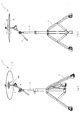
以下、本発明の好ましい実施の形態について添付図面を参照して説明する。まず、図1を参照して、本発明の第1実施の形態におけるシンバルスタンド1の概略構成について説明する。図1(a)は、本発明の第1実施の形態におけるシンバルスタンド1の斜視図であり、図1(b)は、シンバルスタンド1の正面図である。なお、図1(a)では、シンバルスタンド1を斜め下方から視た状態が図示されている。 Hereinafter, preferred embodiments of the present invention will be described with reference to the accompanying drawings. First, a schematic configuration of the cymbal stand 1 according to the first embodiment of the present invention will be described with reference to FIG. FIG. 1A is a perspective view of the cymbal stand 1 according to the first embodiment of the present invention, and FIG. 1B is a front view of the cymbal stand 1. FIG. 1A shows a state in which the cymbal stand 1 is viewed obliquely from below.
図1(a)及び図1(b)に示すように、シンバルスタンド1は、シンバル10を演奏者が所望する位置に設置するためのスタンドであり、伸縮可能な伸縮パイプ2と、その伸縮パイプ2を床面に対して支持する脚部3と、伸縮パイプ2に支持される支持パイプ4と、その支持パイプ4に支持されるロッド5とを主に備えて構成されている。
As shown in FIGS. 1A and 1B, the cymbal stand 1 is a stand for installing the
ロッド5は、シンバル10の中央に穿設された孔部11(図4参照)に挿通可能に形成された棒状の部材である。シンバル10は、いわゆるアコースティックシンバルであり、フエルトで構成される円環状のクッション材6が上面側に当接されると共にピックアップ100が下面側に当接された状態でロッド5に挿通され、めねじを有する締付部材7を、ロッド5の先端部分の外周面に螺刻されたおねじに螺合させて締め付けることにより、シンバル10、クッション材6及びピックアップ100がロッド5に固定されている。
The rod 5 is a rod-like member formed so as to be able to be inserted into a hole 11 (see FIG. 4) drilled in the center of the
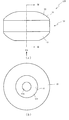
次に、図2から図4を参照して、ピックアップ100の詳細構成について説明する。図2(a)は、ピックアップ100の正面図であり、図2(b)は、図2(a)のIIb方向から視たピックアップ100の底面図である。図3は、図2(a)のIII−III線におけるピックアップ100の断面図である。図4(a)は、シンバルスタンド100の部分断面図であり、図4(b)は、シンバル10が傾いた状態におけるシンバルスタンド100の部分断面図である。なお、図2(a)及び図2(b)では、ケーブル52の図示が省略されている。また、図4(a)及び図4(b)では、ロッド5の軸方向に沿った断面が図示されている。
Next, the detailed configuration of the
図2(a)及び図2(b)に示すように、ピックアップ100は、シンバル10が打撃されたことを検出し、そのシンバルへの打撃に応じた電気信号を音源装置(図示せず)に出力するための装置であり、円筒状のセンサ取着部20と、そのセンサ取着部20の一側(図2(a)上側)に取着される円筒状の第1緩衝部30と、センサ取着部20の他側(図2(a)下側)に取着される円筒状の第2緩衝部40とを備え、センサ取着部20、第1緩衝部30及び第2緩衝部40が同軸上に配設されている。
As shown in FIGS. 2 (a) and 2 (b), the
図3に示すように、センサ取着部20は、ABS樹脂から構成される部材であり、円環状の第1当接部21と、その第1当接部21から離間した位置で第1当接部21に対向して配設される円環状の第2当接部22と、それら第1当接部21及び第2当接部22の間に介設される介設部23とを備えている。なお、本実施の形態では、センサ取着部20がABS樹脂で構成されているが、所定の剛性を有する合成樹脂や鉄や青銅等の金属から構成されていてもよい。
As shown in FIG. 3, the
第1当接部21は、上面(図3上側の面)に第1緩衝部30が当接される部位であり、第1当接部21の厚さ方向(図3上下方向)に沿って貫通形成された第1挿通孔21aを備えている。第1挿通孔21aは、ロッド5(図4(a)参照)が挿通可能に形成された孔であり、第1当接部21の中心部分に形成されている。
The
第2当接部22は、下面(図3下側の面)に第2緩衝部40が当接される部位であり、第2当接部22の厚さ方向(図3上下方向)に沿って貫通形成された第2挿通孔22aを備えている。第2挿通孔22aは、ロッド5が挿通可能に形成された孔であり、第2当接部22の中心部分に形成されている。なお、第1当接部21及び第2当接部22は、略同一形状に形成されており、第1当接部21の第1挿通孔21aと第2当接部22の第2挿通孔22aとが同軸上に配設されている。
The
介設部23は、第1当接部21及び第2当接部22の離間寸法を一定に保持する円筒状の部位であり、第1当接部21の下面側(図3下側)の外周縁全体と第2当接部22の上面側(図3上側)の外周縁全体とが介設部23によって連結されている。これにより、第1当接部21及び第2当接部22に対して互いに近接する方向への力が作用した場合であっても、第1当接部21と第2当接部22との離間寸法を一定に保持することができる。
The
第1当接部21の下面には、円環状のピエゾセンサ50が両面テープ51によって接着されている。ピエゾセンサ50は、センサ取着部20から伝達された振動に応じて電気信号を音源装置(図示せず)に出力するセンサであり、ピエゾセンサ50には音源装置に接続されるケーブル52の一端が取着されている。ケーブル52は、介設部23に貫通形成された孔(図示せず)に挿通されることでケーブル52の他端がセンサ取着部20の外部に配設されている。これにより、ケーブル52の他端を音源装置に接続することができる。なお、ピエゾセンサ50の内径は、第1当接部21の第1挿通孔21aの内径よりも大きく設定されると共に第1当接部21と同軸上に配設されている。また、ピエゾセンサ50が円環状に形成されているので、シンバル10(図4(a)参照)への打撃位置に関わらず、シンバル10の振動を安定的に検出することができる。
An annular
さらに、センサ取着部20の内部、即ち、第1当接部21、第2当接部22及び介設部23により包囲された領域が中空であり、ピエゾセンサ50及び両面テープ51のみがセンサ取着部20の内部に収納されている。従って、ピエゾセンサ50と第2当接部22との間に配設される部材によってピエゾセンサ50の振動が阻害されることを回避できる。
Further, the inside of the
なお、センサ取着部20は、第1当接部21にピエゾセンサ50を接着させた後に、第1当接部21、第2当接部22及び介設部23を互いに接合することで形成されている。また、先に第1当接部21と介設部23とが接合された状態でピエゾセンサ50を第1当接部21に接着し、その後に介設部23と第2当接部22とを接合してもよい。
The
第1緩衝部30は、ピックアップ100をロッド5(図4(a)参照)に挿通させる際に、シンバル10とセンサ取着部20との間に介設される部材であり、センサ取着部20よりも弾性が高い比較的硬質な弾性材料から構成されている。なお、第1緩衝部30に使用される弾性材料としては、例えば、硬度80度(JIS K6253 タイプA)の合成ゴムなどが例示される。第1緩衝部30は、厚さ方向(図3上下方向)に沿って貫通形成された第1軸孔30aと、第1緩衝部30の上面を構成するシンバル当接面31とを備えている。
The
第1軸孔30aは、ロッド5が挿通可能に形成される孔であり、第1緩衝部30は、第1軸孔30aがセンサ取着部20の第1当接部21に形成された第1挿通孔21aに対して同軸上に配設された状態で第1当接部21の上面に接着されている。
The
シンバル当接面31は、ピックアップ100をロッド5に挿通させる際に、シンバル10(図4(a)参照)に当接させるための部位であり、球面状に形成されている。なお、シンバル当接面31は、シンバル10の中央部分に形成されると共に下面側から上面側にむけて球面状に凹設されるカップ部12(図4(a)参照)よりも曲率半径が小さく設定されている。これにより、シンバル当接面31にシンバル10を当接させた際に、シンバル当接面31とシンバル10との接触面積を小さくすることができる。
The
第2緩衝部40は、ピックアップ100をロッド5に挿通させる際に、ワッシャ8(図4(a)参照)とセンサ取着部20との間に介設される部材であり、第1緩衝部30よりも弾性が高い弾性材料から構成されている。なお、第2緩衝部40に使用される弾性材料としては、例えば、硬度60度(JIS K6253 タイプA)の合成ゴム、または、密度0.25g/cm3のフェルトなどが例示される。第2緩衝部40は、厚さ方向(図3上下方向)に沿って貫通形成された第2軸孔40aと、下面側に凹設されるワッシャ収納部41とを備えている。
The
第2軸孔40aは、ロッド5が挿通可能に形成される孔であり、第2緩衝部40は、第2軸孔40aがセンサ取着部20の第2当接部22に形成された第2挿通孔22aに対して同軸上に配設された状態で第2当接部22の下面に接着されている。
The
ワッシャ収納部41は、ピックアップ100がロッド5に挿通される際に、ワッシャ8が収納される部位であり、ワッシャ収納部41の底面を構成する平坦面状のワッシャ当接面41aを備えている。
The
ここで、第1緩衝部30の第1軸孔30aの内径および第2緩衝部40の第2軸孔40aの内径である寸法L1は、第1当接部21の第1挿通孔21aの内径および第2当接部22の第2挿通孔22aの内径であるL2よりも小さな寸法に設定されている。これにより、第1緩衝部30の第1軸孔30aと第2緩衝部40の第2軸孔40aとの内壁面が、第1当接部21の第1挿通孔21aと第2当接部22の第2挿通孔22aとの内壁面よりも内側に位置している。
Here, the dimension L1, which is the inner diameter of the
なお、寸法L1は、ロッド5の外径よりも大きく設定されていてもよく、ロッド5の外径よりも小さく設定されることでロッド5が第1軸孔30a及び第2軸孔40aに圧入可能に形成されていてもよい。寸法L1をロッド5の外径よりも大きく設定した場合には、ピックアップ100をロッド5に挿通する際における第1軸孔30a及び第2軸孔40aの内壁面とロッド5との当接を回避しやすくすることができるので、第1軸孔30a及び第2軸孔40aの内壁面の損耗を抑制することができる。一方、寸法L1をロッド5の外径よりも小さく設定してロッド5に圧入可能に形成した場合には、ピックアップ100をロッド5に挿通させることで、第1軸孔30a及び第2軸孔40aの内壁面によってロッド5の外周面を把持することができるので、ピックアップ100をロッド5に強固に固定することができる。
The dimension L1 may be set larger than the outer diameter of the rod 5, and the rod 5 is press-fitted into the
図4(a)に示すように、ロッド5は、そのロッド5の下方部分を構成すると共に支持パイプ4(図1参照)に支持される大径部5aと、ロッド5の上方部分を構成すると共に大径部5aよりも小径に形成される小径部5bと、それら大径部5a及び小径部5bを連設すると共にロッド5の軸方向(図4(a)上下方向)に垂直な連設面5cとを備えている。また、小径部5bの先端部分(図4(a)上方部分)の外周面には、締付部材7に螺刻されためねじが螺合可能なおねじが螺刻されている。
As shown in FIG. 4A, the rod 5 constitutes a lower portion of the rod 5 and a
ワッシャ8は、金属材料で構成される円環状の部品であり、ワッシャ8の内径がロッド5の大径部5aの外径よりも小さく、かつ、小径部5bの外径よりも大きく設定されている。よって、ロッド5の小径部5bの先端からワッシャ8を挿通させることにより、ワッシャ8がロッド5の連設面5cに当接し、ロッド5に係止される。
The
ピックアップ100は、ロッド5に挿通されたワッシャ8に対して第2緩衝部40のワッシャ収納部41を対向させた状態でロッド5に挿通される。なお、このとき、第2緩衝部40のワッシャ収納部41の形成位置を確認することによって、ピックアップ100をロッド5に挿通させる際の向きを容易に判断することができる。
The
ピックアップ100がロッド5に挿通されると、ワッシャ8がワッシャ収納部41に収納され、ワッシャ当接面41aに当接する。このとき、ワッシャ当接面41aは平坦面状に形成されているので、ピックアップ100が水平な状態を維持しやすくすることができる。よって、シンバル用ピックアップを水平にした状態でピックアップ100を固定しやすくすることができ、ピックアップ100をロッド5に固定する作業を簡素化することができる。
When the
ピックアップ100をロッド5に挿通させた後、シンバル10の孔部11をロッド5に挿通させることで、シンバル10に第1緩衝部30のシンバル当接面31を当接させることができる。さらに、シンバル10がロッド5に挿通された後にはクッション材6がロッド5に挿通され、最後に締付部材7をロッド5に螺合させて締め付けることで、シンバル10及びピックアップ100がロッド5に固定される。
After the
このとき、ピックアップ100は、第1緩衝部30よりも弾性が高い第2緩衝部40が床面に近接する側に配設されるので、床面からロッド5及びワッシャ8を介して第2緩衝部40に伝達された振動を減衰させやすくすることができる。これにより、床面からセンサ取着部20に伝達される振動を低減させることができるので、床面からセンサ取着部20へ伝達された振動がピエゾセンサ50によって検出されることを抑制できる。
At this time, since the
また、センサ取着部20は、そのセンサ取着部20よりも弾性が高い第1緩衝部30と、その第1緩衝部30よりも弾性が高い第2緩衝部40との間に配設されているので、締付部材7の締め付け力によって第1緩衝部30及び第2緩衝部40を弾性変形させることができるので、第1緩衝部30及び第2緩衝部40の弾性復元力を利用してシンバル10及びピックアップ100をロッド5に確実に固定することができる。これにより、センサ取着部20に取着されたセンサ50が、シンバル10又はロッド5とピックアップ100との摺動音を検出することを防止できる。
The
ここで、センサ取着部20はABS樹脂で構成されることで所定の剛性を有し、第1当接部21と第2当接部22との離間寸法が介設部23によって一定に保持されているので、締付部材7による締め付けによって第1当接部21と第2当接部22とが互いに近接することを防止できる。従って、第1当接部21の下面側に取着されたピエゾセンサ50の振動が、締付部材7による締め付けによって阻害されることを回避できる。即ち、ピエゾセンサ50の検出結果が締付部材7の締め付け力による影響を受けることを回避できるので、ピエゾセンサ50は、シンバル10から伝達されるセンサ取着部20の振動に応じた検出結果を出力することができる。よって、シンバル10への打撃に応じた振動を安定的に検出できる。また、演奏者は、締付部材7の締め付け具合を調整することで、演奏時におけるシンバル10の音質や揺れ具合などを演奏者の好みに応じて設定することができる。
Here, the
また、第1緩衝部30及び第2緩衝部40がセンサ取着部20の第1当接部21又は第2当接部22に接着されると共に、第1緩衝部30の第1軸孔30aと第2緩衝部40の第2軸孔40aとの内壁面が、第1当接部21の第1挿通孔21aと第2当接部22の第2挿通孔22aとの内壁面よりも内側に位置している。これにより、第1軸孔30aと第2軸孔40aとの内壁面を、第1挿通孔21a及び第2挿通孔22aの内壁面よりもロッド5に近接させることができる。従って、ピックアップ100に対してロッド5が周方向に相対移動した場合、第1緩衝部30又は第2緩衝部40をロッド5に当接させることができ、第1当接部21及び第2当接部22がロッド5に当接することを防止できる。よって、ロッド5との当接により発生するセンサ取着部20の振動がピエゾセンサ50によって検出されることを防止できる。
In addition, the
さらに、ピエゾセンサ50の内径は、第1当接部21の第1挿通孔21aの内径よりも大きく設定されているので、ピエゾセンサ50がロッド5に当接することを防止できる。
Furthermore, since the inner diameter of the
一方、シンバル10の下面側に位置するピックアップ100の第1緩衝部30は、シンバル10に当接されるシンバル当接面31が球面状に形成されているので、シンバル10とシンバル当接面31との接触面積を小さくすることができる。よって、シンバル10が打撃されて傾いた場合であっても、シンバル10と第1緩衝部30との接触を維持してシンバル10の振動をセンサ取着部20に確実に伝達させつつ、第1緩衝部30との接触によるシンバル10の本来の鳴りへの影響を最小限に抑えることができる。また、シンバル10が打撃されて傾くことによる第1緩衝部30の弾性変形を抑制することができるので、第1緩衝部30の弾性変形により発生する第1緩衝部30のセンサ取着部20に対する摺動を抑制することができる。さらに、第1緩衝部30及び第2緩衝部40が、センサ取着部20の第1当接部21又は第2当接部22に接着されているので、第1緩衝部30及び第2緩衝部40がセンサ取着部20に対して摺動することを防止できる。よって、第1緩衝部30と第2緩衝部40とのセンサ取着部20に対する摺動により発生するセンサ取着部20の振動が、ピエゾセンサ50によって検出されることを回避できる。
On the other hand, in the
また、第1緩衝部30が第2緩衝部40よりも弾性の低い比較的硬質な弾性材料で構成されているので、シンバル10からセンサ取着部20に伝達される振動が第1緩衝部30によって減衰されることを抑制できる。よって、シンバル10への打撃に応じた振動をセンサ取着部20に正確に伝達させやすくすることができる。
Further, since the
さらに、センサ取着部20は、第1緩衝部30に当接する第1当接部21がシンバル10に近接して配設されると共に、ピエゾセンサ50が第1当接部21に取着されている。よって、ピエゾセンサ50が第2当接部22に取着される場合と比べて、ピエゾセンサ50をシンバル10に近接した位置に配設することができるので、シンバル10からセンサ取着部20に伝達される振動をピエゾセンサ50に確実に検出させやすくすることができる。
Further, the
また、第1当接部21と第2当接部22との離間寸法が介設部23によって一定に保持されているので、打撃されたシンバル10の傾きに応じて第1当接部21と第2当接部22との離間寸法が変動することを防止できる。よって、第1当接部21の下面側に取着されたピエゾセンサ50が、打撃されたシンバル10の傾きに伴って変形することを回避でき、その結果、シンバル10が強く打撃されたことによるピエゾセンサ50の破損を防止できる。さらに、センサ取着部20の内部は中空なので、ピエゾセンサ50が自由に振動するための領域を確保することができる。よって、シンバル10への打撃に応じた振動をセンサ取着部20に正確に伝達させやすくすることができる。
In addition, since the distance between the
次に、図5を参照して、第2実施の形態について説明する。第1実施の形態では、第1緩衝部30の第1軸孔30aと第2緩衝部40の第2軸孔40aとの内壁面が、第1当接部21の第1挿通孔21aと第2当接部22の第2挿通孔22aとの内壁面よりも内側に位置することで、第1当接部21及び第2当接部22がロッド5に当接することを防止する場合について説明したが、第2実施の形態では、第1緩衝部230及び第2緩衝部240が第1突設部232又は第2突設部242を備えることで、第1当接部21及び第2当接部22がロッド5に当接することを防止する。なお、上記した第1実施の形態と同一の部分には同一の符号を付して、その説明を省略する。図5は、第2実施の形態におけるピックアップ200の断面図であり、第1実施の形態における図3に対応している。
Next, a second embodiment will be described with reference to FIG. In the first embodiment, the inner wall surfaces of the
図5に示すように、ピックアップ200は、センサ取着部20と、そのセンサ取着部20の第1当接部21の上面に当接される第1緩衝部230と、センサ取着部20の第2当接部22の下面に当接される第2緩衝部240とを主に備えて構成されている。
As shown in FIG. 5, the
第1緩衝部230は、ピックアップ200をロッド5(図4(a)参照)に挿通させる際に、シンバル10(図4(a)参照)とセンサ取着部20との間に介設される部材であり、センサ取着部20よりも弾性が高い比較的硬質な弾性材料から構成されている。第1緩衝部230は、第1軸孔30aと、シンバル当接面31と、第1緩衝部230の下面側(図5下側)における第1軸孔30aの周縁部分から下方に向けて突設される第1突設部232とを備えている。
The
第1突設部232は、センサ取着部20の第1当接部21がロッド5に当接することを防止するための円筒状の部位であり、第1突設部232の外径が第1当接部21の第1挿通孔21aの内径よりも小さく設定されると共に、内周壁が第1軸孔30aの内周壁と面一状に連設されている。また、第1緩衝部230の下面からの第1突設部232の突設高さは、センサ取着部20の第1当接部21の厚さ寸法(図5における上下方向の寸法)よりも大きな寸法に設定されている。従って、第1緩衝部230の下面を同軸上に配設された第1当接部21の上面に当接することにより、第1突設部232を第1挿通孔21aの内部に挿通させることができる。
The first projecting
第2緩衝部240は、ピックアップ200をロッド5に挿通させる際に、ワッシャ8(図4(a)参照)とセンサ取着部20との間に介設される部材であり、第1緩衝部230よりも弾性が高い弾性材料から構成されている。第2緩衝部240は、第2軸孔40aと、ワッシャ収納部41と、第2緩衝部240の上面側(図5上側)における第2軸孔40aの周縁部分から上方に向けて突設される第2突設部242とを備えている。
The
第2突設部242は、センサ取着部20の第2当接部22がロッド5に当接することを防止するための円筒状の部位であり、第2突設部242の外径が第2当接部22の第2挿通孔22aの内径よりも小さく設定されると共に、内周壁が第2軸孔40aの内周壁と面一状に連設されている。また、第2緩衝部240の上面からの第2突設部242の突設高さは、センサ取着部20の第2当接部22の厚さ寸法(図5における上下方向の寸法)よりも大きな寸法に設定されている。従って、第2緩衝部240の上面を同軸上に配設された第2当接部22の下面に当接することにより、第2突設部242を第2挿通孔22aの内部に挿通させることができる。
The second projecting
よって、ピックアップ200にロッド5が挿通された状態において、第1緩衝部230の第1突設部232及び第2緩衝部240の第2突設部242を、ロッド5と第1当接部21の第1挿通孔21a又は第2当接部22の第2挿通孔22aとの間に介設させることができる。これにより、ピックアップ200に対してロッド5が周方向に相対移動した場合であっても、第1突設部232及び第2突設部242をロッド5に当接させることができ、第1当接部21及び第2当接部22がロッド5に当接することを防止できる。従って、ロッド5との当接により発生するセンサ取着部20の振動がピエゾセンサ50によって検出されることを防止できる。
Therefore, in a state where the rod 5 is inserted into the
なお、第1突設部232及び第2突設部242の外径が、第1当接部21の第1挿通孔21a及び第2当接部22の第2挿通孔22aの内径よりも大きく設定され、第1突設部232及び第2突設部242が第1挿通孔21a及び第2挿通孔22aに圧入されていてもよい。これにより、第1緩衝部230及び第2緩衝部240のセンサ取着部20に対する摺動を抑制することができる。また、この場合、第1緩衝部230及び第2緩衝部240をセンサ取着部20に対して接着することを不要とすることができるので、ピックアップ200の製造コストを削減することができる。
The outer diameters of the first projecting
次に、図6を参照して、第3実施の形態について説明する。第1実施の形態では、ピックアップ100がシンバル10の下面に当接される場合について説明したが、第3実施の形態では、ピックアップ300がシンバル10の上面に当接される。なお、上記した各実施の形態と同一の部分には同一の符号を付して、その説明を省略する。図6は、第3実施の形態におけるシンバルスタンドの部分断面図であり、ロッド5の軸方向に沿った断面が図示されている。
Next, a third embodiment will be described with reference to FIG. Although the case where the
図6に示すように、ピックアップ300は、センサ取着部20と、センサ取着部20の第1当接部21に当接される第1緩衝部330と、センサ取着部20の第2当接部22に当接されるノブ部340とを備えている。
As shown in FIG. 6, the
第1緩衝部330は、ピックアップ300をロッド5に挿通させる際に、シンバル10とセンサ取着部20との間に介設される部材であり、センサ取着部20よりも弾性が高い比較的硬質な弾性材料から構成されている。第1緩衝部330は、第1軸孔30aと、シンバル当接面31と、第1突設部232と、シンバル当接面31における第1軸孔30aの周縁部分から下方(図6下側)に向けて突設されるケーブル案内部333とを備えている。ケーブル案内部333は、ピエゾセンサ50に取着されたケーブル52の他端をセンサ取着部20の外部へ案内する円筒状の部位である。
The
また、第1緩衝部330には、第1突設部232の突設先端からケーブル案内部333の突設先端に亘って、第1軸孔30aの軸方向に沿って貫通形成されたケーブル通路333aが形成され、そのケーブル通路333aにケーブル52が挿通されている。これにより、センサ取着部20の内部と外部とがケーブル通路333aによって連通されるので、ケーブル52の他端をセンサ取着部20の外部に配設することができる。
The
さらに、ケーブル案内部333は、その外径がシンバル10の孔部11の内径およびフエルトで構成されると共にロッド5に挿通可能な円環状に形成されるクッション材306の内周壁の内径よりも小さく設定され、ケーブル案内部333の内周壁が第1軸孔30aの内周壁と面一状に連設されている。また、シンバル当接面31からのケーブル案内部333の突設高さは、シンバル10の厚さ寸法(図6における上下方向の寸法)よりも大きな寸法に設定されている。
Furthermore, the outer diameter of the
ノブ部340は、ピックアップ300をロッド5に締付固定するための部材であり、ABS樹脂から構成されている。ノブ部340は、厚さ方向(図6上下方向)に沿って貫通形成されためねじ孔341と、ノブ部340の下面側(図6下側)におけるめねじ孔341の周縁部分から下方に向けて突設されるノブ突設部342とを備えている。
The
めねじ孔341は、ロッド5の外周面に螺刻されたおねじに螺合される部位であり、めねじ孔341の内周壁にはロッド5のおねじに螺合可能なめねじが螺刻されている。
The
ノブ突設部342は、センサ取着部20の第2当接部22がロッド5に当接することを防止する円筒状の部位であり、ノブ突設部342の外径が第2当接部22の第2挿通孔22aの内径よりも小さく設定されると共に、内周壁がめねじ孔341の内周壁に連設されている。また、ノブ部340の下面からのノブ突設部342の突設高さは、センサ取着部20の第2当接部22の厚さ寸法(図6における上下方向の寸法)よりも大きな寸法に設定されている。
The
よって、ピックアップ300にロッド5が挿通された状態において、ノブ部340のノブ突設部342を、ロッド5と第2当接部22の第2挿通孔22aとの間に介設させることができる。これにより、ピックアップ300に対してロッド5が周方向に相対移動した場合、ノブ突設部342をロッド5に当接させることができ、第2当接部22がロッド5に当接することを防止できる。従って、ロッド5との当接により発生するセンサ取着部20の振動がピエゾセンサ50によって検出されることを防止できる。
Therefore, in a state where the rod 5 is inserted into the
ピックアップ300は、シンバル10をロッド5に挿通させた後に、第1緩衝部330のシンバル当接面31をシンバル10の上面に対向させた状態でロッド5に挿通しつつ、ノブ部340のめねじ孔341に螺刻されためねじをロッド5のおねじに螺合させて締め付けることで、クッション材306、シンバル10及びピックアップ300をロッド5に固定することができる。
After the
よって、ピックアップ300とは別部材の締付部材を用いてロッド5にシンバル10及びピックアップ300を固定する場合と比べて、ロッド5にシンバル10及びピックアップ300を固定する作業を簡素化することができる。
Therefore, the work of fixing the
また、ケーブル52が第1緩衝部330のケーブル案内部333に挿通されることで、シンバル10との当接やノブ部340の締め付け力によるケーブル52の損傷を防止できる。
Further, the
次に、図7(a)を参照して、第4実施の形態について説明する。第1実施の形態では、センサ取着部20の介設部23が第1当接部21の下面側の外周縁と第2当接部22の上面側の外周縁とを連結する場合について説明したが、第4実施の形態では、センサ取着部420の介設部423が第1当接部21の下面側における第1挿通孔21aの周縁部分と第2当接部22の上面側における第2挿通孔22aの周縁部分とを連結する。なお、上記した各実施の形態と同一の部分には同一の符号を付して、その説明を省略する。図7(a)は、第4実施の形態におけるピックアップのセンサ取着部420の断面図であり、第1実施の形態における図3に対応している。
Next, a fourth embodiment will be described with reference to FIG. In the first embodiment, the case where the
図7(a)に示すように、センサ取着部420は、第1当接部21と、第2当接部22と、第1当接部21の下面側(図7(a)下側)における第1挿通孔21aの周縁部分と第2当接部22の上面側(図7(a)上側)における第2挿通孔22aの周縁部分とを連結する介設部423とを備えている。
As shown in FIG. 7A, the
介設部423は、第1当接部21と第2当接部22との離間寸法を一定に保持する円筒状の部位であり、内壁面が第1当接部21の第1挿通孔21a及び第2当接部22の第2挿通孔22aの内壁面と面一状に連設されている。介設部423によって第1当接部21と第2当接部22とが互いに近接することを防止できるので、第1当接部21と第2当接部22との離間寸法を一定に保持することができる。
The interposed
次に、図7(b)を参照して、第5実施の形態について説明する。第1実施の形態では、センサ取着部20の介設部23が第1当接部21の下面側の外周縁と第2当接部22の上面側の外周縁とを連結する場合について説明したが、第5実施の形態では、センサ取着部520の介設部23が第1当接部21の下面側の外周縁と第2当接部22の上面側の外周縁とを連結すると共に、介設部423が第1当接部21の下面側における第1挿通孔21aの周縁部分と第2当接部22の上面側における第2挿通孔22aの周縁部分とを連結する。なお、上記した各実施の形態と同一の部分には同一の符号を付して、その説明を省略する。図7(b)は、第5実施の形態におけるピックアップのセンサ取着部520の断面図であり、第1実施の形態における図3に対応している。
Next, a fifth embodiment will be described with reference to FIG. In the first embodiment, the case where the
図7(b)に示すように、センサ取着部520は、第1当接部21と、第2当接部22と、介設部23,423とを備えている。従って、介設部23,423によって第1当接部21と第2当接部22とが互いに近接することを防止できるので、第1当接部21と第2当接部22との離間寸法を一定に保持することができる。
As shown in FIG. 7B, the
また、センサ取着部520の内部、即ち、第1当接部21、第2当接部22及び介設部23,423に包囲された領域は密閉されているので、センサ取着部520の内部に取着されたピエゾセンサ50(図3参照)に埃が付着することを防止できると共に、センサ取着部520の外部からのピエゾセンサ50への接触を防止できるので、ピエゾセンサ50を損傷させにくくすることができる。
Further, since the inside of the
さらに、センサ取着部520が、第1当接部21と第2当接部22との外周縁を連結する介設部23と、第1挿通孔21a及び第2挿通孔22aの周縁部分を連結する介設部423とを備えているので、第1当接部21と第2当接部22とを強固に支持することができる。
Furthermore, the
次に、図7(c)及び図7(d)を参照して、第6実施の形態について説明する。第1実施の形態では、センサ取着部20の介設部23が第1当接部21の下面側の外周縁の全体と第2当接部22の上面側の外周縁の全体とを連結する場合について説明したが、第6実施の形態では、センサ取着部620の複数の介設部623が第1当接部21の下面側の外周縁の一部分と第2当接部22の上面側の外周縁の一部分とを連結する。なお、上記した各実施の形態と同一の部分には同一の符号を付して、その説明を省略する。図7(c)は、第6実施の形態におけるピックアップのセンサ取着部620の正面図であり、図7(d)は、図7(c)のVIId−VIId線におけるセンサ取着部620の断面図である。
Next, a sixth embodiment will be described with reference to FIGS. 7C and 7D. In the first embodiment, the
図7(c)及び図7(d)に示すように、センサ取着部620は、第1当接部21と、第2当接部22と、それら第1当接部21及び第2当接部22の間に介設される介設部623とを備えている。
As shown in FIGS. 7C and 7D, the
介設部623は、第1当接部21及び第2当接部22の離間寸法を一定に保持する湾曲板状の部位であり、周方向等間隔に4つ設けられている。それら4つの介設部623は、第1当接部21の下面側(図7(c)下側)の外周縁の一部と第2当接部22の上面側(図7(c)上側)の外周縁の一部とを連結しているので、第1当接部21及び第2当接部22に対して互いに近接する方向への力が作用した場合であっても、第1当接部21の下面と第2当接部22の上面との離間寸法を一定に保持することができる。また、複数の介設部623が第1当接部21の下面側の外周縁の一部と第2当接部22の上面側の外周縁の一部とを連結しているので、第1当接部21の下面側の外周縁の全体と第2当接部22の上面側の外周縁の全体とを連結する場合と比べて、センサ取着部620の材料コストを抑制することができる。
The
以上、実施の形態に基づき本発明を説明したが、本発明は上記各実施の形態に何ら限定されるものではなく、本発明の趣旨を逸脱しない範囲内で種々の改良変形が可能であることは容易に推察できるものである。 The present invention has been described above based on the embodiments. However, the present invention is not limited to the above embodiments, and various improvements and modifications can be made without departing from the spirit of the present invention. Can be easily guessed.
例えば、上記各実施の形態では、ピエゾセンサ50が円環状に形成される場合について説明したが、必ずしもこれに限られるものではなく、フィルム状のピエゾセンサや円盤状のピエゾセンサを用いてもよい。また、ピエゾセンサ50の代わりに電磁誘導型のセンサや静電容量型のセンサを用いてもよい。
For example, in each of the above embodiments, the case where the
上記各実施の形態では、ピックアップ100,200,300が、いわゆるアコースティックシンバルであるシンバル10の振動を検出する装置として用いられる場合について説明したが、必ずしもこれに限られるものではなく、ピックアップ100,200,300が、いわゆる電子シンバルに用いられてもよい。具体的には、ピックアップ100,200,300を、演奏者によって打撃される打撃体の振動を検出するトリガセンサとして用いてもよい。
In each of the above-described embodiments, the case where the
上記各実施の形態では、センサ取着部20,420,520,620の第1当接部21及び第2当接部22、第1緩衝部30,230,330、第2緩衝部40,240、クッション材6,306、ワッシャ8が円環状に形成される場合について説明したが、必ずしもこれに限れるものではなく、センサ取着部20,420,520,620の第1当接部21及び第2当接部22、第1緩衝部30,230,330、第2緩衝部40,240、クッション材6,306、ワッシャ8が略C字状に形成されてもよい。これにより、ピックアップ100,200,300、クッション材6,306、ワッシャ8をロッド5に装着する際に、ピックアップ100,200,300、クッション材6,306、ワッシャ8をロッド5の軸方向に対して垂直方向から装着することができる。よって、シンバル10をロッドに挿通させたままの状態でピックアップ100,200,300、クッション材6,306、ワッシャ8をロッド5から着脱できるので、ロッド5に装着する作業を簡素化できる。
In each said embodiment, the
上記第1実施および第2実施の形態では、第2緩衝部40,240がワッシャ収納部41を備える場合について説明したが、必ずしもこれに限られるものではなく、ワッシャ収納部41を省略してもよい。これにより、第2緩衝部40,240の形状を簡素化して、第2緩衝部40,240の製造コストを削減できる。この場合、ピックアップ100,200に上下方向を見分けるための目印をつけてもよい。これにより、ピックアップ100,200の上下方向の向きを正しい方向に向けた状態でロッド5にピックアップ100,200を挿通することができる。
In the first and second embodiments, the case where the
また、第2緩衝部40,240の下面側(第2当接部22と対向する面の反対側)にABS樹脂等の第2緩衝部40,240よりも硬質な部材を第2緩衝部40,240と一体に設けてもよい。これにより、ピックアップ100,200をロッド5に固定する際に、ワッシャ8を別途、用意し、ロッド5にワッシャ8を挿通させる作業を不要とすることができるので、ピックアップ100,200をロッド5に固定する作業を簡素化できる。
Further, a member harder than the
さらに、上記各実施の形態では、ピエゾセンサ50がシンバル10に近接して配設されるセンサ取着部20,420,520,620の第1当接部21の下側に取着される場合について説明したが、必ずしもこれに限られるものではなく、第2当接部22の上側に取着されてもよい。これにより、ロッドに固定された状態において、ピエゾセンサ50が第2当接部22の上面に載置された状態にすることができるので、センサ取着部20,420,520,620に接着されたピエゾセンサ50が、重力によってセンサ取着部20,420,520,620から剥がれやすくなることを防止できる。
Further, in each of the above embodiments, the
上記各実施の形態では、センサ取着部20,420,520,620の内部が中空である場合について説明したが、必ずしもこれに限られるものではなく、センサ取着部20,420,520,620の内部に綿やスポンジ等が収納されていてもよい。これにより、ピエゾセンサ50の振動を許容しつつ、シンバル10が打撃された後に残存するセンサ取着部20,420,520,620の振動を早期に収束させることができる。また、センサ取着部20,420,520,620の内部である第2当接部22の上面側にブチルゴム等の振動吸収部材を取着してもよい。これにより、センサ取着部20,420,520,620の振動を早期に収束させることができる。
In each of the above-described embodiments, the case where the inside of the
上記各実施の形態では、本発明が、ロッド5に固定された一枚からなるシンバル10の振動を検出する場合について説明したが、必ずしもこれに限られるものではなく、ハイハットシンバルに本発明を適用してもよい。なお、ハイハットシンバルの場合、上側のシンバルにピックアップ100,200,300の第1緩衝部30,230,330のシンバル当接面31を当接させることで、ハイハットシンバルが打撃されたことによる振動を検出することができる。
In each of the above embodiments, the case where the present invention detects the vibration of the
上記各実施の形態では、第1当接部21の第1挿通孔21a,第2当接部22の第2挿通孔22a、第1緩衝部30,230,330の第1軸孔30a及び第2緩衝部40,240の第2軸孔40aが円形である場合について説明したが、必ずしもこれに限られるものではなく、多角形状等であってもよい。
In each of the above embodiments, the
上記各実施の形態では、第1緩衝部30,230,330及び第2緩衝部40,240が弾性材料から構成される場合について説明したが、必ずしもこれに限られるものではなく、第1緩衝部および第2緩衝部がフエルトで構成されてもよい。第2緩衝部がフエルトで構成された場合には、床面からロッドを介して第2緩衝部に伝達される振動を減衰させやすくすることができるので、床面からセンサ取着部20,420,520,620に伝達される振動を抑制できる。また、第1緩衝部がフエルトで構成される場合には、締付部材7又はノブ部340による締め付けによってフエルトが圧縮されることで、第1緩衝部を硬質にすることができるので、シンバル10からセンサ取着部20,420,520,620に伝達される振動の減衰を抑制することができる。
In each of the above-described embodiments, the case where the
さらに、第1緩衝部を弾性材料で構成しつつ、第2緩衝部をフエルトで構成する場合では、床面からロッド5及びワッシャ8を介して第2緩衝部に伝達される振動を減衰させやすくすることができる共に、シンバル10から第1緩衝部に伝達される振動の減衰を抑制することができる。よって、床面からセンサ取着部20,420,520,620に伝達される振動を低減させつつ、シンバル10からセンサ取着部20,420,520,620に伝達される振動の減衰を抑制できるので、シンバル10への打撃に応じた振動をセンサ取着部20,420,520,620に正確に伝達させやすくすることができる。
Further, when the first buffer portion is made of an elastic material and the second buffer portion is made of felt, it is easy to attenuate the vibration transmitted from the floor surface to the second buffer portion via the rod 5 and the
上記第2実施の形態または第3実施の形態では、第1緩衝部230,330及び第2緩衝部240又はノブ部340が、それぞれ第1突設部232及び第2突設部242又はノブ突設部342を備える場合について説明したが、必ずしもこれに限られるものではなく、第1緩衝部230,330又は第2緩衝部240若しくはノブ部340のいずれか一方が第1突設部232又は第2突設部242若しくはノブ突設部342を備え、第1緩衝部230,330又は第2緩衝部240若しくはノブ部340のいずれか他方の第1突設部232又は第2突設部242若しくはノブ突設部342を省略してもよい。これにより、第1緩衝部230,330又は第2緩衝部240若しくはノブ部340の形状を簡素化して製造コストの抑制を図ることができる。
In the second embodiment or the third embodiment, the
なお、この場合、第1緩衝部230,330又は第2緩衝部240若しくはノブ部340のいずれか一方に形成される第1突設部232又は第2突設部242若しくはノブ突設部342は、センサ取着部20の第1挿通孔21a又は第2挿通孔22aに挿通された状態において、ロッド5と第1挿通孔21a及び第2挿通孔22aの内壁面との間に介設されることが好ましい。これにより、ロッド5がセンサ取着部20に当接することを確実に防止できる。
In this case, the first protruding
第3実施の形態では、ピックアップ300がノブ部340を備える場合について説明したが、必ずしもこれに限られるものではなく、ピックアップがノブ部340の代わりに第2緩衝部40を備え、ピックアップ、シンバル10及びクッション材306をワッシャ8と締付部材7とによってロッド5に固定してもよい。
<その他>
<手段>
技術的思想1のシンバル用ピックアップは、シンバルの中心に穿設される孔部に挿通される棒状のロッドを挿通可能に形成され、前記ロッドを挿通した状態で、前記シンバルに当接させつつ、前記シンバルと共に固定されることで、前記シンバルの振動を検出するシンバル用ピックアップにおいて、前記シンバルの振動を検出するセンサと、そのセンサが取着されると共に所定の剛性を有するセンサ取着部とを備え、前記センサ取着部は、前記ロッドが挿通可能な第1挿通孔を有する第1当接部と、その第1当接部の一面側に対向して配設され前記第1挿通孔に挿通された前記ロッドが挿通可能な第2挿通孔を有する第2当接部と、それら第1当接部および第2当接部の間に介設されることで前記第1当接部の一面側およびその第1当接部の一面側に対向する前記第2当接部の一面側の離間寸法を一定に保持する介設部とを備え、前記センサは、前記第1当接部の一面側または前記第2当接部の一面側に取着される。
技術的思想2のシンバル用ピックアップは、技術的思想1記載のシンバル用ピックアップにおいて、前記第1当接部の他面側に当接され前記センサ取着部よりも弾性が高い材料で構成される第1緩衝部と、前記第2当接部の他面側に当接され前記センサ取着部よりも弾性が高い材料で構成される第2緩衝部とを備え、前記第1緩衝部は、前記第1当接部の第1挿通孔に挿通された前記ロッドが挿通可能な第1軸孔を備え、前記第2緩衝部は、前記第2当接部の第2挿通孔に挿通された前記ロッドが挿通可能な第2軸孔を備えている。
技術的思想3のシンバル用ピックアップは、技術的思想2記載のシンバル用ピックアップにおいて、前記第1緩衝部が弾性材料から構成されると共に、前記第2緩衝部が前記第1緩衝部よりも弾性が高い弾性材料で構成される。
技術的思想4のシンバル用ピックアップは、技術的思想1記載のシンバル用ピックアップにおいて、前記第1当接部の他面側に当接され前記センサ取着部よりも弾性の高い材料で構成される第1緩衝部と、前記第2当接部の他面側に当接されるノブ部とを備え、前記第1緩衝部は、前記第1当接部の第1挿通孔に挿通された前記ロッドが挿通可能な第1軸孔を備え、前記ノブ部は、前記第2当接部の第2挿通孔に挿通された前記ロッドに螺刻されたおねじに螺合可能なめねじが螺刻された第2軸孔を備える。
技術的思想5のシンバル用ピックアップは、技術的思想3又は4に記載のシンバル用ピックアップにおいて、前記センサは、前記第1当接部の一面側に取着される。
技術的思想6のシンバル用ピックアップは、技術的思想2から5のいずれかに記載のシンバル用ピックアップにおいて、前記第1緩衝部と前記第2緩衝部または前記ノブ部とは、前記センサ取着部に接着されると共に、前記第1緩衝部の第1軸孔と前記第2緩衝部または前記ノブ部の第2軸孔との内壁面が、前記第1当接部の第1挿通孔と前記第2当接部の第2挿通孔との内壁面よりも内側に位置している。
技術的思想7のシンバル用ピックアップは、技術的思想2から6のいずれかに記載のシンバル用ピックアップにおいて、前記第1緩衝部または前記第2緩衝部もしくは前記ノブ部の少なくとも一方は、前記第1緩衝部または前記第2緩衝部もしくは前記ノブ部の前記第1当接部または前記第2当接部に当接される面に突設される突設部を備え、前記突設部は、その突設部の外形が前記第1当接部の第1挿通孔および前記第2当接部の第2挿通孔よりも小さく形成されることで、前記第1当接部の第1挿通孔および前記第2当接部の第2挿通孔に挿通可能に形成されている。
技術的思想8のシンバル用ピックアップは、技術的思想2から7のいずれかに記載のシンバル用ピックアップにおいて、前記第1緩衝部は、前記第1当接部が当接される面の反対側の面に形成される球面状のシンバル当接面を備えている。
技術的思想9のシンバル用ピックアップは、技術的思想1から8のいずれかに記載のシンバル用ピックアップにおいて、前記第1当接部と前記第2当接部との間が中空である。
技術的思想10のスタンドは、技術的思想1から9のいずれかに記載のシンバル用ピックアップと、そのシンバル用ピックアップが挿通可能に形成される棒状のロッドとを備える。
<効果>
技術的思想1記載のシンバル用ピックアップによれば、センサ取着部は、所定の剛性を有すると共に、第1当接部の一面側と第2当接部の一面側との離間寸法が介設部によって一定に保持されているので、締付部材の締め付けによって第1当接部と第2当接部とが互いに近接することを防止できる。従って、第1当接部の一面側または第2当接部の一面側に取着されたセンサの振動が、締付部材による締め付けによって阻害されることを回避できる。即ち、センサの検出結果が締付部材の締め付け力による影響を受けることを回避できるので、センサは、シンバルから伝達されるセンサ取着部の振動に応じた検出結果を出力することができる。よって、シンバルへの打撃に応じた振動を安定的に検出できるという効果がある。
さらに、第1当接部と第2当接部との離間寸法が介設部によって一定に保持されているので、ロッドに対するシンバルの傾きに伴って第1当接部と第2当接部との離間寸法が変動することを防止できる。よって、第1当接部の一面側または第2当接部の一面側に取着されたセンサが、シンバルの傾きに伴って変形することを回避できるので、シンバルが強く打撃されることによるセンサの破損を防止できるという効果がある。
技術的思想2記載のシンバル用ピックアップによれば、技術的思想1記載のシンバル用ピックアップの奏する効果に加え、センサ取着部が第1緩衝部および第2緩衝部の間に配設され、それら第1緩衝部および第2緩衝部がセンサ取着部よりも弾性が高い材料で構成されているので、シンバルと共にロッドを挿通した状態でロッドに締付部材を螺合させて締め付けることで、シンバル及びシンバル用ピックアップをロッドに確実に固定することができる。
技術的思想3記載のシンバル用ピックアップによれば、技術的思想2記載のシンバル用ピックアップの奏する効果に加え、ロッドに挿通させる際に、第2緩衝部よりも弾性が低い第1緩衝部をシンバルに近接する側に配設することで、シンバルからセンサ取着部へ伝達される振動の減衰を抑制することができる。このとき、床面に近接する側には第1緩衝部よりも弾性が高い第2緩衝部が配設されるので、床面からロッドを介して第2緩衝部に伝達された振動を減衰させやすくすることができる。
このように、シンバル用ピックアップをロッドに固定する際に、比較的弾性が低い第1緩衝部をシンバルに近接する側に配設しつつ、比較的弾性が高い第2緩衝部を床面に近接する側に配設することで、シンバルからセンサ取着部に伝達される振動の減衰を抑制しつつ、床面からセンサ取着部に伝達される振動を低減させることができるので、シンバルへの打撃に応じた振動をセンサ取着部に正確に伝達させやすくすることができるという効果がある。
技術的思想4記載のシンバル用ピックアップによれば、技術的思想1記載のシンバル用ピックアップの奏する効果に加え、センサ取着部が第1緩衝部およびノブ部の間に配設され、第1緩衝部がセンサ取着部よりも弾性が高い材料で構成されているので、シンバルと共にロッドを挿通した状態で、ロッドにノブ部を螺合させて締め付けることで、シンバル及びシンバル用ピックアップをロッドに確実に固定することができる。
また、シンバルの上面に第1当接部を当接させた状態で、ロッドにノブ部を螺合させて締め付けることによって、シンバル及びシンバル用ピックアップをロッドに固定させることができるので、シンバル用ピックアップとは別部材の締付部材を用いてシンバル及びシンバル用ピックアップをロッドに固定する場合と比べて、シンバル及びシンバル用ピックアップをロッドに固定する作業を簡素化することができるという効果がある。
技術的思想5記載のシンバル用ピックアップによれば、技術的思想3又は4に記載のシンバル用ピックアップの奏する効果に加え、ロッドに挿通させる際に、第1緩衝部をシンバルに当接させることで、第1当接部に取着されたセンサをよりシンバルに近接した位置に配設することができる。よって、シンバルからセンサ取着部に伝達される振動を検出しやすくすることができるという効果がある。
技術的思想6記載のシンバル用ピックアップによれば、技術的思想2から5のいずれかに記載のシンバル用ピックアップの奏する効果に加え、第1緩衝部と第2緩衝部またはノブ部とが、センサ取着部に接着されているので、第1緩衝部および第2緩衝部またはノブ部がセンサ取着部に対して摺動することを防止できる。その結果、第1緩衝部または第2緩衝部もしくはノブ部のセンサ取着部に対する摺動により発生するセンサ取着部の振動がセンサによって検出されることを回避できるという効果がある。
さらに、第1緩衝部の第1軸孔と第2緩衝部またはノブ部の第2軸孔との内壁面が、第1当接部の第1挿通孔と第2当接部の第2挿通孔との内壁面よりも内側に位置しているので、ロッドが挿通された状態において、第1緩衝部の第1軸孔と第2緩衝部またはノブ部の第2軸孔との内壁面を、第1当接部の第1挿通孔および第2当接部の第2挿通孔の内壁面よりもロッドに近接させることができる。これにより、第1当接部および第2当接部がロッドに当接することを防止できるので、ロッドとの当接により発生するセンサ取着部の振動がセンサによって検出されることを防止できるという効果がある。
技術的思想7記載のシンバル用ピックアップによれば、技術的思想2から6のいずれかに記載のシンバル用ピックアップの奏する効果に加え、第1緩衝部または第2緩衝部もしくはノブ部の少なくとも一方に突設される突設部を、第1当接部の第1挿通孔または第2当接部の第2挿通孔に挿通させることができるので、ロッドに挿通された状態において、突設部をロッドと第1当接部の第1挿通孔または第2当接部の第2挿通孔との間に介設させることができる。これにより、第1当接部および第2当接部がロッドに当接することを確実に防止できるので、ロッドとの当接により発生するセンサ取着部の振動がセンサによって検出されることを防止できるという効果がある。
技術的思想8記載のシンバル用ピックアップによれば、技術的思想2から7のいずれかに記載のシンバル用ピックアップの奏する効果に加え、第1緩衝部は、第1当接部に当接される面の反対側の面に形成される球面状のシンバル当接面を備えているので、シンバル当接面をシンバルに当接させつつロッドに固定させることによって、シンバルが打撃された際におけるシンバルと第1緩衝部との接触面積を小さくすることができる。よって、シンバルが打撃されて傾いた場合であっても、シンバルと第1緩衝部との接触を維持してシンバルの振動をセンサ取着部に確実に伝達させつつ、第1緩衝部との接触によるシンバルの本来の鳴りへの影響を最小限に抑えることができる。また、シンバルの傾きに伴う第1緩衝部の変形を抑制することができるので、その第1緩衝部の変形によって第1緩衝部がセンサ取着部に対して摺動することを抑制できる。従って、第1緩衝部のセンサ取着部に対する摺動により発生するセンサ取着部の振動がセンサによって検出されることを回避できるという効果がある。
技術的思想9記載のシンバル用ピックアップによれば、技術的思想1から8のいずれかに記載のシンバル用ピックアップの奏する効果に加え、第1当接部と第2当接部との間が中空なので、センサの自由な振動が阻害されることを防止できる。よって、シンバルへの打撃に応じた振動をセンサ取着部に正確に伝達させやすくすることができるという効果がある。
技術的思想10記載のシンバル用ピックアップを備えたスタンドは、技術的思想1から9のいずれかに記載のシンバル用ピックアップの奏する効果と同様の効果がある。
In the third embodiment, the case where the
<Others>
<Means>
The pick-up for the cymbal of the technical idea 1 is formed so that a rod-shaped rod inserted through a hole formed in the center of the cymbal can be inserted, and in contact with the cymbal while the rod is inserted, In the cymbal pickup for detecting the vibration of the cymbal by being fixed together with the cymbal, a sensor for detecting the vibration of the cymbal, and a sensor attachment portion having the predetermined rigidity while the sensor is attached. And the sensor attachment portion is disposed opposite to the first contact portion having a first insertion hole through which the rod can be inserted, and one surface side of the first contact portion. A second contact portion having a second insertion hole through which the inserted rod can be inserted, and the first contact portion is interposed between the first contact portion and the second contact portion. One side and the first abutting portion An intervening portion that maintains a constant separation dimension on one surface side of the second contact portion facing the surface side, and the sensor is provided on one surface side of the first contact portion or on the second contact portion. Mounted on one side.
The cymbal pickup according to
The cymbal pickup according to technical idea 3 is the cymbal pickup according to
The cymbal pickup according to the technical idea 4 is a cymbal pickup according to the technical idea 1, and is made of a material that is in contact with the other surface side of the first contact part and has higher elasticity than the sensor attachment part. A first buffer portion; and a knob portion that contacts the other surface side of the second contact portion, wherein the first buffer portion is inserted through the first insertion hole of the first contact portion. A first shaft hole through which the rod can be inserted; and the knob portion is threaded by a female screw that can be screwed into a male screw threaded into the rod inserted into the second insertion hole of the second contact portion. The second shaft hole is provided.
The cymbal pickup according to the technical idea 5 is the cymbal pickup according to the technical idea 3 or 4, wherein the sensor is attached to one surface side of the first contact portion.
The cymbal pickup according to the technical idea 6 is the cymbal pickup according to any one of the
The cymbal pickup according to the
The cymbal pickup according to the
The cymbal pickup according to the technical idea 9 is the cymbal pickup according to any one of the technical ideas 1 to 8, wherein a space between the first contact part and the second contact part is hollow.
The stand of the
<Effect>
According to the cymbal pickup described in the technical idea 1, the sensor attachment portion has a predetermined rigidity, and the distance between the one surface side of the first contact portion and the one surface side of the second contact portion is interposed. Since the portion is held constant, it is possible to prevent the first contact portion and the second contact portion from approaching each other by tightening the tightening member. Therefore, it is possible to avoid the vibration of the sensor attached to the one surface side of the first contact portion or the one surface side of the second contact portion from being hindered by the tightening by the tightening member. That is, since the detection result of the sensor can be avoided from being affected by the tightening force of the tightening member, the sensor can output the detection result corresponding to the vibration of the sensor attachment portion transmitted from the cymbal. Therefore, there is an effect that vibration according to the impact on the cymbal can be detected stably.
In addition, since the distance between the first contact portion and the second contact portion is held constant by the interposition portion, the first contact portion and the second contact portion are associated with the inclination of the cymbal with respect to the rod. It is possible to prevent fluctuation of the separation dimension. Therefore, the sensor attached to one surface side of the first contact portion or the one surface side of the second contact portion can be prevented from being deformed with the inclination of the cymbal. There is an effect that can prevent the damage.
According to the cymbal pickup described in the
According to the cymbal pickup described in the technical idea 3, in addition to the effect exhibited by the cymbal pickup described in the
As described above, when the cymbal pickup is fixed to the rod, the first buffer portion having relatively low elasticity is disposed on the side close to the cymbal, and the second buffer portion having relatively high elasticity is close to the floor surface. Since the vibration transmitted from the floor surface to the sensor attachment portion can be reduced while suppressing the attenuation of the vibration transmitted from the cymbal to the sensor attachment portion. There is an effect that it is possible to easily transmit the vibration according to the hitting to the sensor attachment portion accurately.
According to the cymbal pickup described in the technical idea 4, in addition to the effect achieved by the cymbal pickup described in the technical idea 1, the sensor attachment part is disposed between the first buffer part and the knob part, and the first buffer part is provided. The part is made of a material with higher elasticity than the sensor mounting part. With the rod inserted with the cymbal, the knob part is screwed into the rod and tightened to secure the cymbal and cymbal pickup to the rod. Can be fixed to.
In addition, the cymbal and the cymbal pickup can be fixed to the rod by screwing the knob to the rod and tightening the rod while the first contact portion is in contact with the upper surface of the cymbal. Compared with the case where the cymbal and the cymbal pickup are fixed to the rod using a separate fastening member, there is an effect that the operation of fixing the cymbal and the cymbal pickup to the rod can be simplified.
According to the cymbal pickup described in the technical idea 5, in addition to the effect exhibited by the cymbal pickup described in the technical idea 3 or 4, when the first buffer part is brought into contact with the cymbal, The sensor attached to the first contact portion can be disposed at a position closer to the cymbal. Therefore, there is an effect that vibration transmitted from the cymbal to the sensor attachment portion can be easily detected.
According to the cymbal pickup described in the technical idea 6, in addition to the effects exhibited by the cymbal pickup described in any of the
Further, the inner wall surface of the first shaft hole of the first buffer portion and the second shaft hole of the second buffer portion or the knob portion is the second insertion hole of the first contact portion and the second insertion portion of the second contact portion. Since it is located inside the inner wall surface with the hole, the inner wall surface between the first shaft hole of the first buffer portion and the second shaft hole of the second buffer portion or the knob portion when the rod is inserted. The inner wall surfaces of the first insertion hole of the first contact portion and the second insertion hole of the second contact portion can be made closer to the rod. Thereby, since it can prevent that a 1st contact part and a 2nd contact part contact | abut to a rod, it can prevent that the vibration of the sensor attachment part generated by contact | abutting with a rod is detected by a sensor. effective.
According to the cymbal pickup described in the
According to the cymbal pickup described in the
According to the cymbal pickup described in the technical idea 9, in addition to the effect exhibited by the cymbal pickup described in any of the technical ideas 1 to 8, the space between the first contact part and the second contact part is hollow. Therefore, the free vibration of the sensor can be prevented from being hindered. Therefore, there is an effect that it is possible to easily transmit the vibration according to the impact on the cymbal to the sensor attachment portion accurately.
The stand provided with the cymbal pickup described in the
1 シンバルスタンド(スタンド)
5 ロッド
7 締付部材
8 ワッシャ
10 シンバル
11 孔部
20,420,520,620 センサ取着部
21 第1当接部
21a 第1挿通孔
22 第2当接部
22a 第2挿通孔
23,423,623 介設部
30,230,330 第1緩衝部
30a 第1軸孔
31 シンバル当接面
40,240 第2緩衝部
40a 第2軸孔
50 ピエゾセンサ(センサ)
232 第1突設部(突設部)
242 第2突設部(突設部)
340 ノブ部
342 ノブ突設部(突設部)
1 Cymbal stand (stand)
5
232 First protrusion (protrusion)
242 Second protrusion (protrusion)
340
Claims (12)
前記シンバルの振動を検出するセンサと、そのセンサが取着されると共に所定の剛性を有するセンサ取着部とを備え、
前記センサ取着部は、前記ロッドが挿通可能な第1挿通孔を有する第1当接部と、その第1当接部の一面側に対向して配設され前記第1挿通孔に挿通された前記ロッドが挿通可能な第2挿通孔を有する第2当接部と、それら第1当接部および第2当接部の間に介設されることで前記第1当接部の一面側およびその第1当接部の一面側に対向する前記第2当接部の一面側の離間寸法を一定に保持する介設部とを備え、
前記センサは、前記第1当接部の一面側または前記第2当接部の一面側に取着されることを特徴とするシンバル用ピックアップ。 A rod-shaped rod inserted through a hole drilled in the center of the cymbal is formed so that it can be inserted, and while being in contact with the cymbal with the rod inserted, it is fixed together with the cymbal, In the cymbal pickup that detects the vibration of the cymbal,
A sensor for detecting the vibration of the cymbal, and a sensor attachment portion to which the sensor is attached and having a predetermined rigidity;
The sensor attachment portion is disposed opposite to a first contact portion having a first insertion hole through which the rod can be inserted, and one surface side of the first contact portion, and is inserted into the first insertion hole. Further, a second contact portion having a second insertion hole through which the rod can be inserted, and one surface side of the first contact portion by being interposed between the first contact portion and the second contact portion. And an interposition part that keeps the separation dimension of the one surface side of the second contact part facing the one surface side of the first contact part constant,
The cymbal pickup, wherein the sensor is attached to one surface side of the first contact portion or one surface side of the second contact portion.
前記第2当接部の他面側に当接され前記センサ取着部よりも弾性が高い材料で構成される第2緩衝部とを備え、
前記第1緩衝部は、前記第1当接部の第1挿通孔に挿通された前記ロッドが挿通可能な第1軸孔を備え、
前記第2緩衝部は、前記第2当接部の第2挿通孔に挿通された前記ロッドが挿通可能な第2軸孔を備えていることを特徴とする請求項1記載のシンバル用ピックアップ。 A first buffer portion made of a material that is in contact with the other surface side of the first contact portion and has higher elasticity than the sensor attachment portion;
A second buffer portion made of a material that is in contact with the other surface side of the second contact portion and is more elastic than the sensor attachment portion;
The first buffer portion includes a first shaft hole into which the rod inserted through the first insertion hole of the first contact portion can be inserted,
2. The cymbal pickup according to claim 1, wherein the second buffer portion includes a second shaft hole into which the rod inserted through the second insertion hole of the second contact portion can be inserted.
前記突設部は、その突設部の外径が前記第1当接部の第1挿通孔および前記第2当接部の第2挿通孔よりも小さく形成されることで、前記第1当接部の第1挿通孔および前記第2当接部の第2挿通孔に挿通可能に形成されていることを特徴とする請求項2から4のいずれかに記載のシンバル用ピックアップ。The protruding portion is formed such that an outer diameter of the protruding portion is smaller than the first insertion hole of the first contact portion and the second insertion hole of the second contact portion. 5. The cymbal pickup according to claim 2, wherein the pickup is formed so as to be able to be inserted into the first insertion hole of the contact portion and the second insertion hole of the second contact portion.
前記第2当接部の他面側に当接されるノブ部とを備え、
前記第1緩衝部は、前記第1当接部の第1挿通孔に挿通された前記ロッドが挿通可能な第1軸孔を備え、
前記ノブ部は、前記第2当接部の第2挿通孔に挿通された前記ロッドに螺刻されたおねじに螺合可能なめねじが螺刻された第2軸孔を備えることを特徴とする請求項1記載のシンバル用ピックアップ。 A first buffer portion made of a material that is in contact with the other surface side of the first contact portion and is more elastic than the sensor attachment portion;
A knob portion that is in contact with the other surface side of the second contact portion,
The first buffer portion includes a first shaft hole into which the rod inserted through the first insertion hole of the first contact portion can be inserted,
The knob portion includes a second shaft hole in which a female screw that can be screwed into a male screw threaded into the rod inserted into the second insertion hole of the second contact portion is threaded. The cymbal pickup according to claim 1.
前記突設部は、その突設部の外径が前記第1当接部の第1挿通孔および前記第2当接部の第2挿通孔よりも小さく形成されることで、前記第1当接部の第1挿通孔および前記第2当接部の第2挿通孔に挿通可能に形成されていることを特徴とする請求項6又は7に記載のシンバル用ピックアップ。 Wherein at least one of the first shock-absorbing portion or front Symbol knob portion, said first buffer portion or projecting surfaces abutting the first abutment and the second abutment portion of the front Symbol knob portion Provided with a protruding portion,
The protruding portion is formed such that an outer diameter of the protruding portion is smaller than the first insertion hole of the first contact portion and the second insertion hole of the second contact portion. The pick-up for cymbal according to claim 6 or 7 , wherein the pickup is formed so as to be able to be inserted into the first insertion hole of the contact portion and the second insertion hole of the second contact portion.
Priority Applications (3)
| Application Number | Priority Date | Filing Date | Title |
|---|---|---|---|
| JP2011253765A JP5897880B2 (en) | 2011-11-21 | 2011-11-21 | Cymbal pickup and stand with the same |
| CN201210316921.XA CN103137111B (en) | 2011-11-21 | 2012-08-30 | Cymbal sound pick-up and the support for including the cymbal sound pick-up |
| US13/607,824 US8754318B2 (en) | 2011-11-21 | 2012-09-10 | Cymbal pickup and stand provided with the same |
Applications Claiming Priority (1)
| Application Number | Priority Date | Filing Date | Title |
|---|---|---|---|
| JP2011253765A JP5897880B2 (en) | 2011-11-21 | 2011-11-21 | Cymbal pickup and stand with the same |
Publications (3)
| Publication Number | Publication Date |
|---|---|
| JP2013109139A JP2013109139A (en) | 2013-06-06 |
| JP2013109139A5 JP2013109139A5 (en) | 2014-11-20 |
| JP5897880B2 true JP5897880B2 (en) | 2016-04-06 |
Family
ID=48425531
Family Applications (1)
| Application Number | Title | Priority Date | Filing Date |
|---|---|---|---|
| JP2011253765A Expired - Fee Related JP5897880B2 (en) | 2011-11-21 | 2011-11-21 | Cymbal pickup and stand with the same |
Country Status (3)
| Country | Link |
|---|---|
| US (1) | US8754318B2 (en) |
| JP (1) | JP5897880B2 (en) |
| CN (1) | CN103137111B (en) |
Families Citing this family (25)
| Publication number | Priority date | Publication date | Assignee | Title |
|---|---|---|---|---|
| US8729378B2 (en) * | 2010-09-15 | 2014-05-20 | Avedis Zildjian Co. | Non-contact cymbal pickup using multiple microphones |
| US8946536B2 (en) * | 2010-11-16 | 2015-02-03 | Field Electronic Drums, Llc | Electronic cymbal assembly with modular self-dampening triggering system |
| US8742244B2 (en) * | 2011-08-31 | 2014-06-03 | Inmusic Brands, Inc. | Electronic hi-hat cymbal controller |
| JP5897880B2 (en) * | 2011-11-21 | 2016-04-06 | ローランド株式会社 | Cymbal pickup and stand with the same |
| JP5912483B2 (en) * | 2011-12-13 | 2016-04-27 | ローランド株式会社 | Music control device |
| US8889977B1 (en) * | 2012-12-20 | 2014-11-18 | David Rowland Gage | Electrical pickup for stringed musical instrument |
| JP2015121728A (en) * | 2013-12-25 | 2015-07-02 | ローランド株式会社 | Electronic cymbal |
| JP5993885B2 (en) * | 2014-02-27 | 2016-09-14 | 星野楽器株式会社 | Tilters and cymbal stands for musical instruments |
| US9263012B2 (en) * | 2014-03-18 | 2016-02-16 | Avedis Zildjian Co. | Cymbal striking surface |
| JP6446839B2 (en) * | 2014-06-02 | 2019-01-09 | ヤマハ株式会社 | Cymbal washer |
| US10079008B2 (en) | 2016-01-05 | 2018-09-18 | Rare Earth Dynamics, Inc. | Magnetically secured cymbal trigger and choke assembly |
| US10096309B2 (en) | 2015-01-05 | 2018-10-09 | Rare Earth Dynamics, Inc. | Magnetically secured instrument trigger |
| US9761215B2 (en) * | 2015-11-03 | 2017-09-12 | Avedis Zildjian Co. | Techniques for magnetically mounting a transducer to a cymbal and related systems and methods |
| JP6454662B2 (en) * | 2016-07-04 | 2019-01-16 | 星野楽器株式会社 | Cymbal attachment and hi-hat stand |
| US10854179B2 (en) | 2016-11-01 | 2020-12-01 | Mizuho MIYAJIMA | Cymbal support and method for using cymbal support |
| WO2018090798A1 (en) * | 2016-11-17 | 2018-05-24 | Sunland Information Technology Co., Ltd. | System and method for recording user performance of keyboard instrument |
| CN108281128B (en) * | 2016-11-17 | 2021-05-07 | 森兰信息科技(上海)有限公司 | Method and system for recording keyboard instrument user performance |
| JP6210424B1 (en) * | 2017-03-21 | 2017-10-11 | Atv株式会社 | Electronic cymbal |
| US10262636B2 (en) | 2017-06-02 | 2019-04-16 | Avedis Zildjian Co. | Techniques for magnetically mounting a percussion instrument to a cymbal and related systems and methods |
| JP6622783B2 (en) * | 2017-12-07 | 2019-12-18 | 株式会社コルグ | Hi-hat cymbal sound generation device, hi-hat cymbal sound generation method, hi-hat cymbal sound generation program, recording medium |
| US10620020B2 (en) | 2017-12-14 | 2020-04-14 | Yamaha Corporation | Sensor unit that detects a strike |
| US11417304B2 (en) * | 2019-04-15 | 2022-08-16 | Guy Shemesh | Electronic percussion instrument |
| EP4070050A4 (en) * | 2019-12-05 | 2024-01-17 | Sunhouse Tech Inc | Systems and methods for capturing and interpreting audio |
| CA3168096A1 (en) * | 2020-01-20 | 2021-07-29 | Drum Workshop, Inc. | Electronic musical instruments and systems |
| JP2023081746A (en) * | 2021-12-01 | 2023-06-13 | 株式会社エフノート | Electronic cymbal |
Family Cites Families (34)
| Publication number | Priority date | Publication date | Assignee | Title |
|---|---|---|---|---|
| GB2173031A (en) * | 1985-02-07 | 1986-10-01 | Trading Merchandising Service | Musical cymbal/transducer combination |
| US5262585A (en) * | 1990-10-31 | 1993-11-16 | Lenny Greene | Electronic cymbal system |
| US5915289A (en) * | 1997-12-12 | 1999-06-22 | Hart; Peter | Electronic cymbal apparatus |
| JP3639103B2 (en) | 1997-12-24 | 2005-04-20 | 株式会社コルグ | Silent cymbals, electric cymbals and silenced hi-hat cymbals |
| JP3069348U (en) * | 1999-11-03 | 2000-06-16 | 星野楽器株式会社 | Structure of cymbal holder |
| JP3679317B2 (en) * | 2000-08-22 | 2005-08-03 | ローランド株式会社 | Electronic cymbals |
| US6632989B2 (en) * | 2000-08-22 | 2003-10-14 | Roland Corporation | Electronic pad with vibration isolation features |
| AU2001284427A1 (en) * | 2000-09-07 | 2002-03-22 | Shingo Tomoda | Analog electronic drum set, parts for drum stick, analog electronic drum set andfoot-pedal unit |
| US6417434B1 (en) * | 2001-02-09 | 2002-07-09 | Tsun-Chi Lao | Adjustable two layer cymbal structure |
| US6798122B1 (en) * | 2002-11-05 | 2004-09-28 | The United States Of America As Represented By The Secretary Of The Navy | Lightweight underwater acoustic projector |
| US7323632B2 (en) * | 2003-08-19 | 2008-01-29 | Martin Richard Wachter | Percussion transducer |
| JP4236611B2 (en) * | 2003-12-26 | 2009-03-11 | ローランド株式会社 | Electronic percussion instrument |
| JP4183625B2 (en) * | 2004-01-07 | 2008-11-19 | ローランド株式会社 | Electronic percussion instrument |
| JP4190426B2 (en) * | 2004-01-08 | 2008-12-03 | ローランド株式会社 | Electronic percussion instrument |
| JP2006133529A (en) * | 2004-11-05 | 2006-05-25 | Yamaha Corp | Electronic percussion instrument |
| US7468483B2 (en) * | 2005-01-19 | 2008-12-23 | Roland Corporation | Electronic percussion instrument and displacement detection apparatus |
| JP4556894B2 (en) * | 2006-03-23 | 2010-10-06 | ヤマハ株式会社 | Electronic percussion instrument device |
| CN1862657A (en) * | 2006-04-28 | 2006-11-15 | 上海博瑞汽车配件制造有限公司 | Instant turn-off delay turn-on high-efficient adaptive automobile electronic loudspeaker |
| JP4247272B2 (en) * | 2006-12-27 | 2009-04-02 | ローランド株式会社 | Electronic hi-hat cymbal |
| JP4208926B2 (en) * | 2007-01-15 | 2009-01-14 | 株式会社コナミデジタルエンタテインメント | Electronic percussion instrument operation detection device |
| JP4967743B2 (en) * | 2007-03-25 | 2012-07-04 | ヤマハ株式会社 | Performance information input device, percussion instrument and sensor unit |
| JP5082802B2 (en) * | 2007-11-27 | 2012-11-28 | ヤマハ株式会社 | Hi-hat electronic pad |
| JP5071071B2 (en) * | 2007-11-27 | 2012-11-14 | ヤマハ株式会社 | Electronic pad for striking |
| US8288639B2 (en) * | 2007-12-31 | 2012-10-16 | Alessandro Carraro | Union group for locking a music instrument to a support element |
| JP5194318B2 (en) * | 2008-12-08 | 2013-05-08 | 株式会社コルグ | Percussion pickup, electric percussion instrument, and adjustment method thereof |
| CN201470073U (en) * | 2009-08-05 | 2010-05-19 | 鈊象电子股份有限公司 | Sound and shock absorption effects |
| WO2011054099A1 (en) * | 2009-11-09 | 2011-05-12 | Billdidit Inc. | Hi-hat wash control device |
| US8729378B2 (en) * | 2010-09-15 | 2014-05-20 | Avedis Zildjian Co. | Non-contact cymbal pickup using multiple microphones |
| US8946536B2 (en) * | 2010-11-16 | 2015-02-03 | Field Electronic Drums, Llc | Electronic cymbal assembly with modular self-dampening triggering system |
| US8269088B1 (en) * | 2011-03-14 | 2012-09-18 | Tsun-Chi Liao | Cymbal support structure |
| CN202258288U (en) * | 2011-09-09 | 2012-05-30 | 得理乐器(珠海)有限公司 | Novel electronic cymbal |
| US8436240B1 (en) * | 2011-10-19 | 2013-05-07 | Billdidit Inc. | Quick release coupling |
| JP5897880B2 (en) * | 2011-11-21 | 2016-04-06 | ローランド株式会社 | Cymbal pickup and stand with the same |
| TWM435020U (en) * | 2012-01-06 | 2012-08-01 | K H S Musical Instr Co Ltd | Stageless copper cymbals adjusting and positioning device |
-
2011
- 2011-11-21 JP JP2011253765A patent/JP5897880B2/en not_active Expired - Fee Related
-
2012
- 2012-08-30 CN CN201210316921.XA patent/CN103137111B/en not_active Expired - Fee Related
- 2012-09-10 US US13/607,824 patent/US8754318B2/en active Active
Also Published As
| Publication number | Publication date |
|---|---|
| US8754318B2 (en) | 2014-06-17 |
| CN103137111B (en) | 2017-07-14 |
| US20130125735A1 (en) | 2013-05-23 |
| JP2013109139A (en) | 2013-06-06 |
| CN103137111A (en) | 2013-06-05 |
Similar Documents
| Publication | Publication Date | Title |
|---|---|---|
| JP5897880B2 (en) | Cymbal pickup and stand with the same | |
| JP2013109139A5 (en) | ||
| JP5067214B2 (en) | Electronic percussion instrument | |
| JP5446437B2 (en) | Impact detection device | |
| JP2013142872A (en) | Electronic percussion instrument | |
| US9099072B2 (en) | Cymbal silencer | |
| JP6372105B2 (en) | Electronic percussion instrument | |
| EP2863383A2 (en) | Drum silencer | |
| EP2884486B1 (en) | Installation structure for acoustic transducer | |
| US10467996B2 (en) | Cymbal damping tool and method of producing the same | |
| EP3346461B1 (en) | Bass drum damper and bass drum | |
| JP5163070B2 (en) | Electronic percussion instrument | |
| JP7192453B2 (en) | sensor unit and cymbal | |
| TWI643182B (en) | Electronic drum and cymbal with spider web-like sensor | |
| US11244661B2 (en) | Sound damping device and vibration detection device | |
| JP2018155995A (en) | Electronic cymbal | |
| JP5329109B2 (en) | Electronic percussion instrument | |
| TWM542840U (en) | Pickup suitable for stringed instrument | |
| JP5733370B2 (en) | Impact detection device | |
| JP3130135U (en) | Electronic equipment legs | |
| JP5626297B2 (en) | Electronic percussion instrument | |
| WO2019180814A1 (en) | Detection device and detection method | |
| JP2016180775A (en) | Sensor device and attachment structure of sensor device | |
| JP2023169365A (en) | vibration sensor | |
| CN117730366A (en) | Electronic percussion instrument and method for fixing face |
Legal Events
| Date | Code | Title | Description |
|---|---|---|---|
| A621 | Written request for application examination |
Free format text: JAPANESE INTERMEDIATE CODE: A621 Effective date: 20140904 |
|
| A521 | Written amendment |
Free format text: JAPANESE INTERMEDIATE CODE: A523 Effective date: 20141007 |
|
| A977 | Report on retrieval |
Free format text: JAPANESE INTERMEDIATE CODE: A971007 Effective date: 20150423 |
|
| A131 | Notification of reasons for refusal |
Free format text: JAPANESE INTERMEDIATE CODE: A131 Effective date: 20150512 |
|
| A521 | Written amendment |
Free format text: JAPANESE INTERMEDIATE CODE: A523 Effective date: 20150702 |
|
| TRDD | Decision of grant or rejection written | ||
| A01 | Written decision to grant a patent or to grant a registration (utility model) |
Free format text: JAPANESE INTERMEDIATE CODE: A01 Effective date: 20160209 |
|
| A61 | First payment of annual fees (during grant procedure) |
Free format text: JAPANESE INTERMEDIATE CODE: A61 Effective date: 20160303 |
|
| R150 | Certificate of patent or registration of utility model |
Ref document number: 5897880 Country of ref document: JP Free format text: JAPANESE INTERMEDIATE CODE: R150 |
|
| LAPS | Cancellation because of no payment of annual fees |