JP5885501B2 - Electronic device, its control method, program, and recording medium - Google Patents
Electronic device, its control method, program, and recording medium Download PDFInfo
- Publication number
- JP5885501B2 JP5885501B2 JP2011288268A JP2011288268A JP5885501B2 JP 5885501 B2 JP5885501 B2 JP 5885501B2 JP 2011288268 A JP2011288268 A JP 2011288268A JP 2011288268 A JP2011288268 A JP 2011288268A JP 5885501 B2 JP5885501 B2 JP 5885501B2
- Authority
- JP
- Japan
- Prior art keywords
- unit
- distance
- electronic device
- control unit
- notification
- Prior art date
- Legal status (The legal status is an assumption and is not a legal conclusion. Google has not performed a legal analysis and makes no representation as to the accuracy of the status listed.)
- Expired - Fee Related
Links
Images


Classifications
-
- G—PHYSICS
- G06—COMPUTING; CALCULATING OR COUNTING
- G06F—ELECTRIC DIGITAL DATA PROCESSING
- G06F3/00—Input arrangements for transferring data to be processed into a form capable of being handled by the computer; Output arrangements for transferring data from processing unit to output unit, e.g. interface arrangements
- G06F3/01—Input arrangements or combined input and output arrangements for interaction between user and computer
- G06F3/03—Arrangements for converting the position or the displacement of a member into a coded form
- G06F3/041—Digitisers, e.g. for touch screens or touch pads, characterised by the transducing means
- G06F3/0416—Control or interface arrangements specially adapted for digitisers
- G06F3/04166—Details of scanning methods, e.g. sampling time, grouping of sub areas or time sharing with display driving
-
- G—PHYSICS
- G06—COMPUTING; CALCULATING OR COUNTING
- G06F—ELECTRIC DIGITAL DATA PROCESSING
- G06F3/00—Input arrangements for transferring data to be processed into a form capable of being handled by the computer; Output arrangements for transferring data from processing unit to output unit, e.g. interface arrangements
- G06F3/01—Input arrangements or combined input and output arrangements for interaction between user and computer
- G06F3/03—Arrangements for converting the position or the displacement of a member into a coded form
- G06F3/041—Digitisers, e.g. for touch screens or touch pads, characterised by the transducing means
- G06F3/044—Digitisers, e.g. for touch screens or touch pads, characterised by the transducing means by capacitive means
-
- G—PHYSICS
- G06—COMPUTING; CALCULATING OR COUNTING
- G06F—ELECTRIC DIGITAL DATA PROCESSING
- G06F2203/00—Indexing scheme relating to G06F3/00 - G06F3/048
- G06F2203/041—Indexing scheme relating to G06F3/041 - G06F3/045
- G06F2203/04101—2.5D-digitiser, i.e. digitiser detecting the X/Y position of the input means, finger or stylus, also when it does not touch, but is proximate to the digitiser's interaction surface and also measures the distance of the input means within a short range in the Z direction, possibly with a separate measurement setup
-
- G—PHYSICS
- G06—COMPUTING; CALCULATING OR COUNTING
- G06F—ELECTRIC DIGITAL DATA PROCESSING
- G06F2203/00—Indexing scheme relating to G06F3/00 - G06F3/048
- G06F2203/041—Indexing scheme relating to G06F3/041 - G06F3/045
- G06F2203/04108—Touchless 2D- digitiser, i.e. digitiser detecting the X/Y position of the input means, finger or stylus, also when it does not touch, but is proximate to the digitiser's interaction surface without distance measurement in the Z direction
Landscapes
- Engineering & Computer Science (AREA)
- General Engineering & Computer Science (AREA)
- Theoretical Computer Science (AREA)
- Human Computer Interaction (AREA)
- Physics & Mathematics (AREA)
- General Physics & Mathematics (AREA)
- Position Input By Displaying (AREA)
- Power Sources (AREA)
- Studio Devices (AREA)
Description
本発明は、電子機器、その制御方法、およびプログラム、並びに記録媒体に関し、特に、ユーザインターフェースとしてタッチパネル又はタッチセンサーを有する電子機器に関する。 The present invention relates to an electronic device, a control method thereof, a program, and a recording medium, and particularly relates to an electronic device having a touch panel or a touch sensor as a user interface.
一般に、パーソナルコンピュータ、PDA(Personal Digital Assistant)、又は携帯電話などの電子機器では、ユーザインターフェースとしてタッチパネル又はタッチセンサー(以下タッチ操作部と総称する)が用いられている。 In general, a touch panel or a touch sensor (hereinafter collectively referred to as a touch operation unit) is used as a user interface in an electronic device such as a personal computer, a PDA (Personal Digital Assistant), or a mobile phone.
タッチ操作部では、所謂機械式のボタンと異なって、押し圧の際の押し込み感などの操作感が乏しく、このため、ユーザにとってタッチ操作が電子機器に受け付けられたか否かを判断することが難しいことがある。このような点に対して、例えば、タッチ操作が受け付けられたことを音声及び振動で報知する手法が知られている(特許文献1参照)。 Unlike a so-called mechanical button, the touch operation unit has a poor operational feeling such as a pressing feeling during pressing, and thus it is difficult for the user to determine whether the touch operation has been accepted by the electronic device. Sometimes. For such a point, for example, a method of notifying that a touch operation has been accepted by sound and vibration is known (see Patent Document 1).
ところで、タッチ操作が電子機器に受け付けられたことをユーザに違和感なく報知するためには、タッチ操作後即座に報知音を発生させることが望ましい。 By the way, in order to notify the user that the touch operation has been accepted by the electronic device without any sense of incongruity, it is desirable to generate a notification sound immediately after the touch operation.
ところが、電子機器に搭載された音声発生回路には、一般に音声サンプリングクロックを発生するための回路としてPLL(Phase Locked Loop)回路が用いられることが多い。そして、PLL回路の起動には所定の時間が必要であることが知られている。 However, a sound generation circuit mounted on an electronic device generally uses a PLL (Phase Locked Loop) circuit as a circuit for generating an audio sampling clock. It is known that a predetermined time is required to activate the PLL circuit.
PLL回路は、基準信号と電圧制御発振器との出力(発振出力という)との位相差が一定になるように電圧制御発振器をフィードバック制御する。PLL回路では、基準信号と発振出力を分周した信号との位相差を表す差信号が示す電圧に応じて電圧制御発振器が制御して、基準信号に同期した発振出力を電圧制御発振器から出力する。 The PLL circuit feedback-controls the voltage-controlled oscillator so that the phase difference between the reference signal and the output of the voltage-controlled oscillator (referred to as oscillation output) is constant. In the PLL circuit, the voltage controlled oscillator controls according to the voltage indicated by the difference signal indicating the phase difference between the reference signal and the signal obtained by dividing the oscillation output, and the oscillation output synchronized with the reference signal is output from the voltage controlled oscillator. .
この際、差信号の交流成分をフィルタ回路でカットするが、差信号(入力信号)のジッタを十分に除去するため、フィルタ回路の時定数は不可避的に大きくなる。このため、フィルタ回路の応答特性はなだらかとなる。つまり、フィルタ回路の応答には時間が掛かってしまい、その結果、基準信号が入力されてから基準信号に同期した発振出力を得るまでの時間が長くなってしまう。 At this time, the AC component of the difference signal is cut by the filter circuit, but the time constant of the filter circuit inevitably increases in order to sufficiently remove the jitter of the difference signal (input signal). For this reason, the response characteristic of the filter circuit becomes gentle. In other words, the response of the filter circuit takes time, and as a result, the time from when the reference signal is input until the oscillation output synchronized with the reference signal is obtained becomes longer.
このようなPLL回路を用いた場合には、ユーザによるタッチ操作を受け付けてから報知音を発生させるまでにタイムラグが発生してしまうことになる。一方、タッチ操作から報知音発生までのタイムラグを低減するため、PLL回路を常に起動するようにすると、常に電力が消費されてしまうことになる。 When such a PLL circuit is used, there is a time lag from when the touch operation by the user is received until the notification sound is generated. On the other hand, if the PLL circuit is always activated in order to reduce the time lag from the touch operation to the generation of the notification sound, power is always consumed.
従って、本発明の第1の目的は、操作部における操作から当該操作の受け付けに対する報知までの間のタイムラグを少なくすることのできる電子機器、その制御方法、およびプログラム、並びに記録媒体を提供することにある。 Accordingly, a first object of the present invention is to provide an electronic device, a control method thereof, a program, and a recording medium that can reduce a time lag between an operation in an operation unit and a notification for acceptance of the operation. It is in.
本発明の第2の目的は、タッチパネルなどの操作部における操作を受け付けた際に当該受け付けを報知する際、消費電力を低減することのできる電子機器、その制御方法、およびプログラム、並びに記録媒体を提供することにある。 A second object of the present invention is to provide an electronic device capable of reducing power consumption, a control method thereof, a program, and a recording medium when notifying the reception when an operation in an operation unit such as a touch panel is received. It is to provide.
上記の目的を達成するために、本発明による電子機器は、操作部に対する操作に応じて、操作の受付を示す報知を行う報知手段と、前記報知手段を動作させるためのクロック信号を前記報知手段に供給するクロック供給手段と、前記操作部を操作するための操作体の前記操作部への近接を検知する検知手段と、前記操作体と前記操作部との距離が、前記報知手段が前記報知を行うべき操作を受け付ける距離よりも大きい距離である第1の距離以内に近接したことが前記検知手段によって検知されると、前記クロック供給手段を起動するように制御する制御手段と、有することを特徴とする。 To achieve the above object, an electronic apparatus according to the present invention, in response to the operation on the operation unit, and a notification means for performing notification indicating the acceptance of the operation, the notification means of the clock signal to operate the notification means A clock supply means for supplying to the detection section, a detection means for detecting the proximity of the operation body for operating the operation section to the operation section, and a distance between the operation body and the operation section is determined by the notification section. Control means for controlling to start the clock supply means when the detection means detects that the proximity is within a first distance that is greater than a distance for receiving an operation to be performed. Features.
本発明によれば、操作部に対する操作が受け付けられたことを報知する際、操作から報知までのタイムラグを低減して、しかも消費電力を低減することができる。 According to the present invention, when notifying that an operation on the operation unit has been accepted, the time lag from the operation to the notification can be reduced, and the power consumption can be reduced.
以下、本発明の実施の形態による電子機器の一例について図面を参照して説明する。なお、ここでは、電子機器の1つである撮像装置を例に挙げて説明する。 Hereinafter, an example of an electronic apparatus according to an embodiment of the present invention will be described with reference to the drawings. Note that, here, an imaging apparatus that is one of electronic devices will be described as an example.
図1は、本発明の実施の形態による撮像装置の一例を示すブロック図である。 FIG. 1 is a block diagram illustrating an example of an imaging apparatus according to an embodiment of the present invention.
図示の撮像装置は、タッチパネル機能付表示装置を備えており、レンズユニットの交換を行うことのできるレンズユニット交換式撮像装置である。 The illustrated imaging apparatus includes a display device with a touch panel function, and is a lens unit exchangeable imaging apparatus capable of exchanging lens units.
撮像装置100は撮像素子(例えば、CCD又はCMOSセンサ)121を有しており、撮像素子121にはレンズ210、絞り211、レンズマウント202及び102、そして、シャッター144を介して被写体の光学像が結像する。撮像素子121は、結像した光学像に応じた電気信号(アナログ信号)を出力する。このアナログ信号はA/D変換部122においてA/D変換処理によってデジタル信号に変換される。
The
A/D変換部122の出力であるデジタル信号は、メモリ制御部124およびシステム制御部120の制御下で画像データとしてメモリ127に格納される。画像処理部123はA/D変換部122の出力であるデジタル信号又はメモリ制御部124によってメモリ127から読み出された画像データに対して所定の画素補間処理および色変換処理を行う。
The digital signal that is the output of the A /
なお、画像処理部123には、適応離散コサイン変換(ADCT)などによって画像データを圧縮伸長する圧縮・伸長回路が備えられている。この圧縮・伸長回路によってメモリ127に格納された画像データについて圧縮処理又は伸長処理を行った後、当該画像データがメモリ127に書き込まれる。
The
さらに、画像処理部123は、画像データのコントラスト値を算出して、当該コントラスト値に応じて撮影画像の合焦状態を測定する。
Further, the
メモリ制御部124は、A/D変換部122、画像処理部123、表示装置110、および外部着脱メモリ部130とメモリ127との間における画像データの送受を制御する。A/D変換部122の出力であるデジタル信号は画像処理部123およびメモリ制御部124を介して、又は直接メモリ制御部124を介してメモリ127に書き込まれる。
The
表示装置110は、例えば、タッチパネル機能を備える液晶ディスプレイであり、液晶パネル表示部125、バックライト照明部126、およびタッチパネル部154を有している。
The
液晶パネル表示部125はシステム制御部120の制御下でメモリ127の画像表示データ用領域に格納されたメニュー画面又は外部着脱メモリ部130に格納された画像ファイル(画像データ)を画像として表示する。バックライト照明部126は液晶パネル表示部125の背面を照明する。
The liquid crystal
バックライト照明の光源素子として、例えば、LED、有機EL、又は蛍光管などが用いられる。そして、バックライト照明部126はシステム制御部120の制御下で照明の点灯又は消灯を行う。
As a light source element for backlight illumination, for example, an LED, an organic EL, or a fluorescent tube is used. The
タッチパネル部154ではタッチ検出方式として、静電容量の変化を検知してタッチ操作の有無を判定する静電容量方式が用いられる。タッチパネル部154に対するタッチ操作によって撮影設定および表示設定に関するメニュー操作を行うことができる。
In the
さらに、撮影画像をスルー画像として液晶パネル表示部125に表示させるライブビュー撮影の際に、液晶パネル表示部125に表示された被写体画像をタッチ操作によって選択すると、当該被写体画像に対して、システム制御部120はAF(オートフォーカス)処理を行う。
Furthermore, when a subject image displayed on the liquid crystal
なお、静電容量に関して複数の閾値を設定すれば、例えば、操作体(例えば、指)をタッチパネル154に近接させた状態とタッチ操作とを区別して検知することができる。
If a plurality of thresholds are set for the capacitance, for example, it is possible to distinguish and detect a state in which an operating body (for example, a finger) is brought close to the
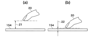
図2は、図1に示すタッチパネル部154に対する指の近接とタッチ操作との相違を説明するための図である。そして、図2(a)はタッチパネル部154に指を近接させた状態を示す図であり、図2(b)はタッチパネル部154にタッチ操作を行った状態を示す図である。
FIG. 2 is a diagram for explaining the difference between the proximity of the finger to the
ここでは、タッチパネル部154における静電容量の変化を検知する際、第1および第2の閾値が設定されている。この第1および第2の閾値は、例えば、不揮発性メモリ128に記憶されている(ここでは、第1の閾値<第2の閾値)。さらに、当該第1および第2の閾値に関して、それぞれ指20とタッチパネル部154の表面との距離が設定されている。
Here, when detecting a change in capacitance in the
ここでは、第1の閾値に対応する距離を第1の距離21とし、第2の閾値に対応する距離を第2の距離22とする。この第2の距離はタッチパネル部154のタッチ操作が検知可能な距離である。
Here, a distance corresponding to the first threshold is a
いま、ユーザがタッチパネル部154に指20を近づけていくと、タッチパネル部154における静電容量が変化する。そして、システム制御部120はこの静電容量の変化を検知容量として検知する。検知容量が第1の閾値以上となると、システム制御部120はユーザの指20とタッチパネル部154の表面との距離が第1の距離以下(例えば、数cm以下)であると判定する。
Now, when the user brings the
さらに、ユーザがタッチパネル部154に指を近づけていき、検知容量が第2の閾値以上となると、システム制御部120はユーザの指20とタッチパネル部154の表面との距離が第2の距離以下であると判定する。図示のように、この第2の距離はユーザの指20がタッチパネル部154の表面にほぼ接触する距離である。
Furthermore, when the user brings the finger closer to the
再び、図1を参照して、システム制御部120は撮像装置100全体の制御を司る。メモリ127には撮影の結果得られた静止画像データおよび動画像データが記録されるとともに、再生用表示のための画像データが格納される。メモリ127は所定枚数の静止画像データおよび動画像データを格納するための十分な記憶量を備えている。
Again referring to FIG. 1, the
なお、メモリ127にはシステム制御部120のプログラムスタック領域、ステータス記憶領域、演算用領域、ワーク用領域、および画像表示データ用領域が確保されている。各種の演算の際には、システム制御部120はメモリ127の演算用領域を用いて演算を行う。
In the
不揮発性メモリ128は電気的に消去・記録可能なメモリであり、例えば、フラッシュメモリ又はEEPROMなどが用いられる。そして、不揮発性メモリ128には、撮影状態を示す情報が保存されるとともに、撮像装置100を制御するプログラムおよびタッチ報知音に係る音声データなどが格納される。
The
外部着脱メモリ部130として、例えば、コンパクトフラッシュ(登録商標)又はSDカードなどの記録媒体が用いられる。外部着脱メモリ部130は撮像装置100に対して着脱可能であって、画像ファイルが記録され、必要に応じて画像ファイルが読み出される。
As the external
電源部131は、電池、電池検出回路、DC−DCコンバータ、および通電するブロックを切り替えるスイッチ回路など(図示せず)を有している。電源部131は電池の装着の有無、電池の種類、および電池残量の検出を行う。そして、当該検出結果およびシステム制御部120の制御下で、電源部131はDC−DCコンバータを制御して、所定の電圧を所定の期間、図示の各ブロック部に供給する。
The
シャッター制御部141は測光部142で測光された測光情報に基づいて、絞り211を制御するレンズ制御部203と協働して、シャッター144を制御する。
The
測光部142はAE(自動露出)処理を行う際に用いられる。測光部142にはレンズ210に入射した光が絞り211、レンズマウント202および102、そして、測光用レンズ(図示せず)を介して与えられる。これによって、測光部42は光学像として結像した画像の露出状態を測定する。
The
また、測光部142は、ストロボユニット300と協働してEF(フラッシュ調光)処理を行う。なお、ストロボユニット300は、AF補助光の投光機能およびフラッシュ調光機能を有する。
The
測距部143はAF処理を行う際に用いられる。測距部143にはレンズ210に入射した光が絞り211、レンズマウント202および102、そして、測距用ミラー(図示せず)を介して与えられる。これによって、測距部143は光学像として結像した画像の合焦状態を測定する。
The
なお、ライブビュー撮影の際には、測距部143は、画像処理部123から出力された画像データに応じて得られたコントラスト値に基づいて撮影画像の合焦状態を測定することができる。
In live view shooting, the
カメラ制御部140は、システム制御部120の制御下でシャッター制御部141、測光部142、および測距部143と通信を行って撮影の際の一連の動作を制御する。また、カメラ制御部140は、レンズユニット200およびストロボユニット300の制御を行う。
The
再生スイッチ132、メニュー(MENU)スイッチ133、モードダイアル134、レリーズスイッチ135、その他操作部136、電子ダイアル137、および電源スイッチ138は、システム制御部120に対して各種の動作指示を入力するための操作部である。この操作部においては、スイッチおよびダイアルの他に、視線検知によるポインティングおよび音声認識装置などが用いられることもある。
The
再生表示スイッチ132の操作によって、システム制御部120は表示装置110に所定の画像データを表示画像として表示する再生表示モードとなる。外部着脱メモリ部130に格納された画像ファイルを再生表示する際には、再生スイッチ132が操作される。再生表示モードにおいて、再生表示スイッチ132が操作されると、システム制御部120は再生表示モードから撮影モードに切り替える。
By operating the
メニュースイッチ133の操作によって、システム制御部120は表示装置110に各種項目一覧を表示する。各種項目一覧には、撮影に関する撮影状態設定、記録媒体のフォーマット、時計の設定、現像パラメータの設定、およびユーザ機能設定(カスタム機能の設定)などがある。
By operating the
モードダイアル134の操作によって、システム制御部120は自動撮影モード、プログラム撮影モード、シャッター速度優先撮影モード、絞り優先撮影モード、マニュアル撮影モード、ポートレート撮影モード、風景撮影モード、スポーツ撮影モード、夜景撮影モード、および動画モードなどの各機能撮影モードの切り替えを行う。
By operating the
レリーズスイッチ135はレリーズボタンの半押しによって第1のスイッチ信号(SW1)をオンし、レリーズボタンの全押しによって第2のスイッチ信号(SW2)をオンする。SW1がオンすると、システム制御部120の制御下で、AF処理、AE処理、AWB(オートホワイトバランス)処理、EF(フラッシュ調光)処理などが開始される。
The release switch 135 turns on the first switch signal (SW1) when the release button is half-pressed, and turns on the second switch signal (SW2) when the release button is fully pressed. When SW1 is turned on, under the control of the
SW2がオンすると、システム制御部120の制御下で撮像素子121から読み出されたアナログ信号がA/D変換部122、メモリ制御部124を介してメモリ127に画像データとして書き込まれる撮像処理が行われる。
When SW2 is turned on, an imaging process is performed in which an analog signal read from the
さらに、画像処理部123およびメモリ制御部124における演算結果に基づいた現像処理が行われる。また、メモリ127から画像データが読み出されて、画像処理部123において圧縮処理が行われて、外部着脱メモリ部130に当該画像データが書き込む記録処理が行われる。つまり、SW2のオンによって、上記の一連の処理が開始される。
Further, development processing based on the calculation results in the
その他操作部136は各種ボタンスイッチを有しており、その他操作部136の操作に応じて、システム制御部120は撮影モード、連写モード、セット、マクロ、ページ送り、フラッシュ設定、メニュー移動、ホワイトバランス選択、撮影画質選択、露出補正、および日付/時間設定などを行う。
The other operation unit 136 has various button switches. In response to the operation of the other operation unit 136, the
さらに、その他操作部136にはライブビュー撮影開始および停止を行うスイッチ、上下左右方向スイッチ、再生画像のズーム倍率変更スイッチ、画像表示オン/オフスイッチ、撮影直後に撮影画像を自動再生するクイックレビューオン/オフスイッチ、および再生画像を消去するスイッチなどが備えられている。 In addition, the other operation unit 136 includes a switch for starting and stopping Live View shooting, an up / down / left / right switch, a zoom magnification change switch for a reproduced image, an image display on / off switch, and a quick review on for automatically reproducing a photographed image immediately after photographing. A / off switch and a switch for erasing the reproduced image are provided.
また、その他操作部136には、JPEGおよびMPEG圧縮の各圧縮率、撮像素子の出力をデジタル化して記録するCCDRAWモードを選択する圧縮モードスイッチが備えられている。 In addition, the other operation unit 136 is provided with a compression mode switch for selecting a CCD RAW mode for digitizing and recording each compression rate of JPEG and MPEG compression and an output of the image sensor.
加えて、その他操作部136には、レリーズボタン半押し状態でAF合焦状態を保持するワンショットAFモードと連携してAF動作を続けるサーボAFモードを設定するAFモード設定スイッチなどが備えられている。 In addition, the other operation unit 136 includes an AF mode setting switch for setting a servo AF mode for continuing the AF operation in cooperation with the one-shot AF mode for holding the AF in-focus state when the release button is pressed halfway. Yes.
電子ダイアル137の操作によって、システム制御部120はシャッタースピード、絞り値、および露出などの設定を行う。電源スイッチ138の操作によって、システム制御部120は電源部131のオンおよびオフを切り替える。
By operating the electronic dial 137, the
加えて、システム制御部120は、電源スイッチ138の操作に応じて、レンズユニット200、ストロボユニット300、および外部着脱メモリ部130に対する電源オンおよび電源オフの切り替えを行う。
In addition, the
タイマー139は時計機能、カレンダー機能、タイマーカウンター機能、およびアラーム機能を有している。タイマー139はスタンバイモードからスリープモードへの移行時間およびアラーム通知などのシステム管理に用いられる。 The timer 139 has a clock function, a calendar function, a timer counter function, and an alarm function. The timer 139 is used for system management such as a transition time from the standby mode to the sleep mode and alarm notification.
赤外光受発光部150は表示装置110の近傍に配置されている。赤外光受発光部150は赤外光発光体および受光回路を備え、赤外光発光体から所定の間隔で発光された光が被検出物体で反射されて、当該反射光が受光回路で検出される。反射光の検知によって、システム制御部120は規定の位置に被検出物体が位置するか否かを判定する。
The infrared light receiving / emitting unit 150 is disposed in the vicinity of the
赤外光受発光部150を用いれば、ユーザがファインダー(図示せず)を覗いているか否かを検知することができる。ユーザがファインダーを覗いていると検知すると、システム制御部120は、例えば、バックライト照明126を消灯して、ユーザの眼にバックライト照明126の光が入って眩しく感じることを防止する。
If the infrared light receiving / emitting unit 150 is used, it is possible to detect whether or not the user is looking through a finder (not shown). When detecting that the user is looking into the viewfinder, the
マイクロフォン151は、外部からの音声などを取得して、当該音声を電気信号(音声信号)に変換する。この音声信号は音声コーデック部152に与えられる音声コーデック部152は、音声信号の符号化・復号化を行う処理回路、マイク・スピーカを駆動するアンプ、音声信号に含まれるノイズを除去するフィルタ回路、および音声信号(音響信号ともいう)レベルを調整するための調整回路を有している。
The
図3は、図1に示す音声コーデック部152を詳細に示すブロック図である。
FIG. 3 is a block diagram showing in detail the
音声コーデック部152はマイクアンプ401を有しており、マイクアンプ401はマイクロフォン151から出力されるアナログ信号を増幅する。マイクアップ401で増幅されたアナログ信号はA/Dコンバータ402でデジタル信号に変換される。
The
このデジタル信号(録音信号)は、後述するように、スイッチ410、ハイパスフィルタ(HPF)407、ローパスフィルタ(LPF)409、オートレベルコントロール部(ALC)409、およびスイッチ412を介してコーデック部403に与えられる。そして、コーデック部403はデジタル信号をオーディオインターフェースフォーマットに符号化する。この符号化信号はシステム制御部120に与えられる。
As will be described later, this digital signal (recorded signal) is sent to the
コーデック部403はオーディオインターフェースフォーマットに符号化された符号化信号を復号化してデジタル信号に変換する。例えば、コーデック部403は、システム制御部403から符号化信号(音響信号)を受けると、この符号化信号を復号化して再生信号(デジタル信号)として出力する。
The
コーデック部403で復号化された再生信号はスイッチ411を介してD/Aコンバータ(D/A変換手段)404に与えられて、ここでアナログ信号に変換される。D/Aコンバータ404の出力であるアナログ信号は、スピーカアンプ405で増幅されてスピーカ153に与えられる。そして、スピーカ153はスピーカアンプ405の出力に応じた音響又は音声を出力する。
The reproduction signal decoded by the
このようにして、音声コーデック部152は音響データ又は音声データに応じて音響再生を行う。
In this manner, the
図示のように、コーデック部403にはPLL(Phase Locked Loop)回路406が接続されている。このPLL回路406はシステム制御部120から出力される基準信号に基づいてコーデック部403で用いるサンプリング周波数の発振信号fvcoを生成する。
As shown in the figure, a PLL (Phase Locked Loop)
図4は、図3に示すPLL回路406を詳細に示すブロック図である。
FIG. 4 is a block diagram showing in detail the
図示のPLL回路406は電圧制御発振器603を有しており、電圧制御発振器603の出力(発振信号)fvcoが分周器604に与えられて、1/N/分周される(Nは2以上の整数)。分周器604の出力である分周信号(fcomp=fvco/N)は位相比較器601に与えられる。
The
位相比較器601は、システム制御部120から与えられる基準信号Frefと分周信号fcompとの位相を比較して位相差を示す差信号を出力する。この差信号はフィルタ回路602で交流成分がカットされて、電圧制御発振器602に出力される。
The
電圧制御発振器602は差信号が示す電圧に応じて発振信号(fvco=N×fref)の発振周波数(サンプリング周波数ともいう)を変化させる。そして、この発振信号fvco(クロック信号)はコーデック部430(図3)に与えられる。
The voltage controlled
このようにして、PLL回路406は基準信号frefに同期し基準信号のN倍の発振信号fvco(クロック信号)を発生させる。
In this way, the
ところが、前述したように、差信号のジッタ成分を十分除去するためには、フィルタ回路602の時定数を大きくする必要がある。このため、基準信号frefが入力された後、基準信号に同期する発振信号fvcoを得るまでに時間を要してしまうことになる。
However, as described above, it is necessary to increase the time constant of the
再び図3を参照すると、HPF407は、例えば、風切り音などの低周波成分を除去する。HPF(ハイパスフィルタ)部である。LPF408は音声信号のうち音声帯域成分を通過させる。ALC409は音声レベルを調整するためのものである。
Referring to FIG. 3 again, the
スイッチ410はA/Dコンバータ402を選択的にコーデック部403又はHPF407に接続する。スイッチ411はD/Aコンバータ404を選択的にALC409又はコーデック部403に接続する。
The
スイッチ410によってA/Dコンバータ402とHPF407とが接続されている際には、スイッチ411によってコーデック部403とD/Aコンバータ404とが接続される。そして、この際には、スイッチ412がオンされて、A/Dコンバータ402から録音信号がALC409を介してコーデック部403に与えられる。
When the A /
一方、スイッチ410によってコーデック部403とHPF407とが接続されると、スイッチ411によってALC409とD/Aコンバータ404とが接続される。この際、スイッチ412はオフされて、コーデック部403から再生信号がALC409を介してD/Dコンバータ404に与えられる。
On the other hand, when the
このように、スイッチ410〜412によってHPF407、LPF408、ALC409で構成される回路に録音信号および再生信号のどちらを通過させるかを選択することができる。
As described above, it is possible to select which of the recording signal and the reproduction signal is passed through the circuit constituted by the
加えて、再生信号をHPF407、LPF408、およびALC部409を通過させることなく、スイッチ411によってコーデック部403から直接D/Aコンバータ404に出力することができる。
In addition, the playback signal can be directly output from the
そして、音声コーデック部152を用いて、マイクロフォン151で取得した音声などの音響を録音信号(符号化信号)としてシステム制御部120はメモリ127又は外部着脱メモリ部130に記録する。
Then, using the
また、システム制御部120は不揮発性メモリ部128および外部着脱メモリ部130に記録された音響データを音声コーデック部152で再生した、音声などの音響としてスピーカ153から出力する。
Further, the
なお、図示されていないが、システム制御部120は音声コーデック部152に備えられたマイクアンプ401、A/Dコンバータ402、D/Aコンバータ404、スピーカアンプ405、およびPLL回路406についてその電力供給を独立してオン/オフを制御する。そして、システム制御部120は音声コーデック部152全体の電力供給を一括してオン/オフ制御することもできる。
Although not shown, the
再び図1を参照して、レンズマウント102および202は撮像装置100をレンズユニット200と接続するためのインターフェースである。コネクタ101および201は撮像装置100をレンズユニット200と電気的に接続するためのものである。そして、レンズユニット200はカメラ制御部140によって制御される。
Referring again to FIG. 1, the lens mounts 102 and 202 are interfaces for connecting the
レンズユニット200は交換タイプのレンズユニットであり、レンズユニット200に備えられたレンズ210を介して被写体の光学像が絞り211、レンズマウント202および102、シャッター144を通過して、撮像素子121に結像される。
The
レンズユニット200にはレンズ制御部204が備えられている。そして、レンズ制御部204には距離検出部203が接続され、距離検出部203からレンズ制御部204にレンズ210から被写体までの距離が検出距離として与えられる。
The
レンズ制御部204は、メモリおよび不揮発性メモリ(ともに図示せず)を備え、メモリにはレンズ動作用の定数、変数、およびプログラムなどが記憶される。また、不揮発性メモリにはレンズユニット200に固有の番号などの識別情報、管理情報、開放絞り値、最小絞り値、および焦点距離などの機能情報、現在および過去の各設定値などが保持される。
The
レンズ制御部204は、カメラ制御部140の制御下で測距部143又は画像処理部123で測定された合焦状態に応じて、レンズ210のフォーカシングを制御する。
The
これによって、レンズ制御部204は撮像素子121に入射する光学像の結像位置を変更してAF動作を行う。また、レンズ制御部204は絞り211の制御およびレンズ210のズーミングを制御する。
Thereby, the
アクセサリシュー111および301は撮像装置100をストロボユニット300と接続するためのインターフェースである。ストロボユニット300はアクセサリシュー301によってアクセサリシュー111に接続される。アクセサリシュー、301はアクセサリシュー111うちにおいて、ストロボユニット300と撮像装置100と電気的に接続するためのインターフェースである。
ストロボユニット300はストロボ発光制御部302を有し、ストロボ発光制御部302はカメラ制御部140の制御下でキセノン管などの発光部(図示せず)を発光させる際、測光部142による測定結果に基づいて発光量および発光タイミングを制御する。
The
続いて、図1に示す撮像装置100におけるタッチ操作の受け付け処理について説明する。
Next, touch operation acceptance processing in the
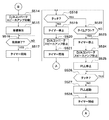
図5Aおよび図5Bは、図1に示す撮像装置100におけるタッチ操作の受け付け処理を説明するためのフローチャートである。なお、図5Aおよび図5Bに示すフローチャートに係る処理は、システム制御部120において行われる。
5A and 5B are flowcharts for explaining a touch operation acceptance process in the
タッチ操作の受け付け処理が開始されると、システム制御部120はタッチパネル部154における検出容量が第1の閾値1以上であるか否かを判定する。つまり、システム制御部120はユーザの指がタッチパネル部154の表面に近接したか否かを判定する(ステップS500)。
When the touch operation acceptance process is started, the
検出容量が第1の閾値未満であると(ステップS500において、NO)、システム制御部120は待機する。一方、検出容量が第1の閾値以上であると(ステップS500において、YES)、システム制御部120はユーザの指がタッチパネル部154の表面に近接したとする。そして、システム制御部120は音声コーデック部152のPLL回路406に電力供給を行って、基準信号frefをPLL回路406に出力しPLL回路406を起動する(ステップS501)。
If the detected capacity is less than the first threshold value (NO in step S500),
続いて、システム制御部120はユーザの指がタッチパネル部154に近接している時間を計測するため、タイマー139を起動して計時を開始する(ステップS502)。
Subsequently, the
タイマー139を起動した後、システム制御部120は再度、検出容量が第1の閾値以上であるか否かを判定する(ステップS503)。検出容量が第1の閾値未満であると(ステップS503において、NO)、システム制御部120はユーザによる指の近接が解除されたとして、タイマー139の計時を停止してそのカウント値をリセットする(ステップS504)。
After starting the timer 139, the
続いて、システム制御部120はPLL回路406に対する電力供給を停止するとともに、基準信号frefの出力を停止して(ステップS505)、タッチ操作の受け付け処理を終了する。
Subsequently, the
検出容量が第1の閾値以上であると(ステップS503において、YES)、システム制御部120は未だユーザの指が近接状態にあるとして、検出容量が第2の閾値以上であるか否かを判定する(ステップS506)。
If the detected capacity is equal to or greater than the first threshold (YES in step S503),
検出容量が第2の閾値以上であると(ステップS506において、YES)、システム制御部120はユーザの指がタッチパネル部154をタッチしたとする。そして、システム制御部120はタイマー139の計時を停止して、タイマー139をリセットする(ステップS507)。その後、システム制御部120は、後述するステップS514の処理に移行する。
If the detected capacity is equal to or greater than the second threshold (YES in step S506),
検出容量が第2の閾値未満であると(ステップS506において、NO)、システム制御部120はユーザの指がタッチパネル部154にタッチしていないとする。そして、システム制御部120はタイマー139の計時時間(カウント値)が所定の計時時間を超えたか否かを判定する。つまり、システム制御部120はタイマー139がタイムアウトしたか否かを判定する(ステップS508)。
If the detected capacity is less than the second threshold (NO in step S506),
タイマー139がタイムアウトしていないと(ステップS508において、NO)、システム制御部120はステップS503の処理に戻る。一方、タイマー139がタイムアウトすると(ステップS508において、YES)、システム制御部120はタイマー139の計時を停止してタイマー139をリセットする(ステップS509)。
If timer 139 has not timed out (NO in step S508),
次に、システム制御部120は基準信号frefの出力を停止するとともに、PLL回路406に対する電力供給を停止する(ステップS510)。その後、システム制御部120は再度、検出容量が第2の閾値以上であるか否かを判定する(ステップS511)。
Next, the
検出容量が第2の閾値以上であると(ステップS511において、YES)、システム制御部120は前述のようにしてPLL回路406を起動する(ステップS512)。そして、システム制御部120は後述するステップS514の処理に進む。
If the detected capacity is greater than or equal to the second threshold (YES in step S511),
検出容量が第2の閾値未満であると(ステップS511において、NO)、システム制御部120は操作者の指が近接状態にあるか否かを判定する(ステップS513)。つまり、システム制御部120は検出容量が第1の閾値以上であるか否かを判定する。
If the detected capacity is less than the second threshold (NO in step S511),
検出容量が第1の閾値以上であると(ステップS513において、YES)、システム制御部120はステップS511の処理に戻る。一方、検出容量が第1の閾値未満であると(ステップS513において、NO)、システム制御部120はタッチ操作の受け付け処理を終了する。
If the detected capacity is greater than or equal to the first threshold (YES in step S513),
ステップS514において、システム制御部120は音声コーデック部152のD/Aコンバータ404、スピーカアンプ405、およびその他ブロックに電力供給を行って、音声コーデック部152を起動する。続いて、システム制御部120は、例えば、不揮発性メモリ部128に予め記録されているタッチ報知音データを音声コーデック部152に与える。
In step S514, the
これによって、音声コーデック部512はタッチ報告音データに応じた再生信号を生成して、スピーカ153から音響として出力する(ステップS515)。
Thereby, the
続いて、システム制御部120はタッチ報知音の発音が終了したか否かを判定する(ステップS516)。ここでは、例えば、マイクロフォン151から入力されるタッチ報知音に応じてタッチ報知音が終了したか否かが判定される。
Subsequently, the
タッチ報知音の発音が終了しないと(ステップS516において、NO)、システム制御部120は待機する。一方、タッチ報知音の発音が終了すると(ステップS516において、YES)、システム制御部120は、ユーザがタッチパネル部154をタッチしている時間を計測するため、タイマー139による計時を開始する(ステップS517)。
If the generation of the touch notification sound is not completed (NO in step S516),
続いて、システム制御部120は検出容量が第2の閾値以上であるか否かを判定する(ステップS518)。検出容量が第2の閾値未満であると(ステップS518において、NO)、システム制御部120はタッチ操作が解除されたとして、タイマー139を停止して、タイマー139をリセットする(ステップS519)。
Subsequently, the
その後、システム制御部120は音声コーデック部152のD/Aコンバータ404、スピーカアンプ405、およびその他ブロックに対する電力供給を停止する(ステップS520)。続いて、システム制御部120はユーザの指がタッチパネル部154に近接している時間を計測するため、タイマー139による計時を開始して(ステップS521)、ステップS503の処理に戻る。
Thereafter, the
検出容量が第2の閾値以上であると(ステップS518において、YES)、システム制御部120はタッチ状態が継続しているとして、タイマー139がタイムアウトしたか否かを判定する(ステップS522)。タイマー139がタイムアウトしていないと(ステップS522において、NO)、システム制御部120はステップS518の処理に戻る。
If the detected capacity is greater than or equal to the second threshold (YES in step S518),
タイマー139がタイムアウトすると(ステップS522において、YES)、システム制御部120はタイマー139を停止して、タイマー139をリセットする(ステップS523)。そして、システム制御部120は音声コーデック部152のD/Aコンバータ部404、スピーカアンプ405、およびその他ブロックの電力供給を停止する(ステップS524)。
When timer 139 times out (YES in step S522),
続いて、システム制御部120はPLL回路496に対する基準信号frefの出力を停止するとともに、PLL回路406の電力供給を停止する(ステップS525)。そして、システム制御部120は検出容量が第2の閾値以上であるか否かを判定する(ステップS526)。
Subsequently, the
検出容量が第2の閾値以上であると(ステップS526において、YES)、システム制御部120はタッチ状態が継続しているとして、待機する。一方、検出容量が第2の閾値未満であると(ステップS526において、NO)、システム制御部120はタッチ操作が解除されたとして、前述したようにして、PLL回路406を起動する(ステップS527)。その後、システム制御部120はタイマー139による計時を開始して(ステップS528)、ステップS503の処理に戻る。
If the detected capacity is greater than or equal to the second threshold (YES in step S526),
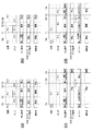
図6は、図5Aおよび図5Bで説明したタッチ操作受け付け処理の際の音声コーデック部152の動作タイミングを説明するための図である。そして、図6(a)はタッチ操作の際の動作タイミングを示す図であり、図6(b)はタッチ報知音が図6(a)の場合よりも長い場合の動作タイミングを示す図である。また、図6(c)は指の近接を検知した後タッチを検知していない状態が長く継続した場合の動作タイミングを示す図であり、図6(d)はタッチ状態が長く継続した場合の動作タイミングを示す図である。
FIG. 6 is a diagram for explaining the operation timing of the
図6(a)において、いま、時刻T0で、システム制御部120が指の近接を検知したとする。これによって、システム制御部120はPLL回路406を起動する。また、時刻T1で、システム制御部120はタッチを検知すると、音声コーデック部152のD/Aコンバータ404、スピーカアンプ405、およびその他ブロックの電力供給を行う。そして、システム制御部は時刻T1でタッチ報知音の発音を開始する。
In FIG. 6A, it is assumed that the
時刻T2で、システム制御部120はタッチ報知音の発音の終了を確認したとする。そして、時刻T3で、指の近接が解除されると(近接オフ)、システム制御部120は音声コーデック部152のD/Aコンバータ404、スピーカアンプ405、およびその他ブロックの電力供給を停止する。さらに、時刻T3において、システム制御部120はPLL回路406を停止する。
Assume that at time T2, the
上述のように、システム制御部120が指の近接を検知した時点で、PLL回路406を起動するようにしたので、PLL回路406(つまり、フィルタ回路602)の時定数が大きくても、近接からタッチまでの間にPLL回路496を安定的に動作させることができる。
As described above, since the
つまり、指のタッチを検知してからPLL回路406を起動する場合に比べて、タッチ検知から報知音発音までの時間を短縮することができる。さらに、指の近接が検知されないと、PLL回路406の動作を停止するとともに、音声コーデック部152の各ブロックに対する電力供給を停止するので、撮像装置100における消費電力を低減することができる。
That is, compared with the case where the
また、音声コーデック部152においてD/Aコンバータ404、スピーカアンプ405、およびその他のブロックの起動は、PLL回路406の起動と比べて短時間で行える。このため、D/Aコンバータ404、スピーカアンプ405、およびその他のブロックの起動はタッチ検知と同時に行う。
In the
この結果、図6(a)に示す時刻T0からT1までの期間において、PLL回路406以外の音声コーデック部152の各ブロックに対する電力供給を停止させることができる。そして、これによっても、撮像装置100における消費電力を低減することができる。
As a result, power supply to each block of the
なお、指の近接を検知したタイミングで音声コーデック部152の全ブロックに対する電力供給を開始するようにしてもよい。このようにすれば、タッチ検知から報知音発音までの時間を、D/Aコンバータ部404、スピーカアンプ405、およびその他ブロックの起動時間分だけ低減することができる。
Note that power supply to all blocks of the
さらに、上述の例では、第1および第2の閾値を設定して、指の近接およびタッチを検知するようにしたが、指の近接の検知に関して、さらに第3の閾値を設定するようにしてもよい。この場合には、第3の閾値<第1の閾値<第2の閾値である。 Further, in the above-described example, the first and second threshold values are set to detect the proximity and touch of the finger. However, the third threshold value is further set for the detection of the proximity of the finger. Also good. In this case, third threshold <first threshold <second threshold.
ここでは、検出容量が第3の閾値以上となった際に、PLL回路406を起動する。そして、検出容量が第1の閾値以上となると、音声コーデック部152のD/Aコンバータ部404、スピーカアンプ405、およびその他ブロックに対する電力供給を開始する。
Here, the
このようにすれば、撮像装置100における消費電力をさらに低減させることができるばかりでなく、タッチ検知から報知音発音まで時間をさらに短縮することができる。
In this way, not only can the power consumption in the
続いて、タッチ報知音が図6(a)の場合よりも長い場合の動作について説明する。図6(b)において時刻T1までの動作は図6(a)と同様であるので説明を略する。 Next, an operation when the touch notification sound is longer than that in the case of FIG. In FIG. 6B, the operation up to time T1 is the same as that in FIG.
図6(b)に示す例では、時刻T2ではタッチが解除され(タッチオフ)、時刻T3では近接が解除された(近接オフ)とする。図6(b)においては、タッチ報知音の発音時間が長いので、近接オフ、つまり、時刻T3の時点では、タッチ報知音の発音が終了していない。 In the example shown in FIG. 6B, it is assumed that the touch is released at time T2 (touch off), and the proximity is released at time T3 (proximity off). In FIG. 6B, since the sound generation time of the touch notification sound is long, the sound generation of the touch notification sound is not completed when the proximity is turned off, that is, at time T3.
このため、時刻T3においては、システム制御部120はPLL回路406の動作停止および音声コーデック部152の各ブロックに対する電力供給停止を行わない。そして、時刻T4で、システム制御部120はタッチ報知音の発音の終了を確認したとすると、システム制御部120は音声コーデック部152のD/Aコンバータ404、スピーカアンプ405、およびその他ブロックの電力供給を停止する。さらに、時刻T4において、システム制御部120はPLL回路406を停止する。
Therefore, at time T3, the
このように、近接オフの時点で、タッチ報知音の発音が終了していないと、タッチ報知音の発音終了を待って、D/Aコンバータ404、スピーカアンプ405、およびその他ブロックの電力供給を停止するとともに、PLL回路406を停止する。これによって、タッチ報知音の発音中に音声コーデック部152の動作が停止してしまうことを防止することができる。
As described above, when the sound of the touch notification sound is not finished when the proximity is off, the power supply to the D /
次に、指の近接を検知した後タッチを検知していない状態が長く継続した場合の動作について説明する。 Next, an operation when a state in which no touch is detected after detecting the proximity of a finger continues for a long time will be described.
図6(c)に示す例では、時刻T0で、システム制御部120が指の近接を検知して、PLL回路406を起動する。この際、前述したように、システム制御部120は指がタッチパネル部154に近接し状態である時間を計測するため、タイマー139による計時を開始する。そして、時刻T1において、システム制御部120はタイムアウトの判定を行ったものとする。
In the example shown in FIG. 6C, the
これによって、システム制御部120はタイマー139の計時を停止してタイマー139をリセットする。そして、システム制御部120はPLL回路406を停止することになる。
As a result, the
その後、時刻T2においてタッチを検知すると、システム制御部120はPLL回路406を起動する。そして、時刻T3において、システム制御部120は音声コーデック部152のD/Aコンバータ部404、スピーカアンプ405、およびその他ブロックに対する電力供給を開始して、タッチ報知音の発音を実行する。
Thereafter, when a touch is detected at time T2, the
このように、指がタッチパネル部154に近接している状態が所定の時間継続している場合には、ユーザに近接する意図がないとして、PLL回路406の動作を停止して、消費電力を低減する。
As described above, when the state where the finger is in proximity to the
ここで、時刻T2においてタッチを検知してから時刻T3でタッチ報知音を発音させるので、タッチ検知からタッチ報知音の発音までにタイムラグが生じる。このため、タッチパネル部154における検出容量の変化を監視することが望ましい。
Here, since the touch notification sound is generated at time T3 after the touch is detected at time T2, there is a time lag between the touch detection and the generation of the touch notification sound. For this reason, it is desirable to monitor the change of the detection capacity in the
例えば、指の近接を検知しているがタッチを検知していない状態において、検出容量が所定の容量以下である場合に、システム制御部120はタイマー139による計時を開始する。そして、タイムアウトした後に、検出容量の変化量が所定の変化量を超え、且つ検出容量の変化が、指がタッチパネル部154に接近する方向と一致している場合に、システム制御部120はPLL回路406を起動する。
For example, in the state where the proximity of the finger is detected but the touch is not detected, when the detected capacity is equal to or smaller than a predetermined capacity, the
このようにすれば、近接からタッチに移行する動作を検知すると、システム制御部120はPLL回路406を起動するので、タッチ検知よりも前にPLL回路406が起動されることになる。この結果、タッチ検知からタッチ報知音の発音でまでに生じるタイムラグを低減することができ、さらに、消費電力を低減することができる。
In this way, when detecting the movement from proximity to touch, the
次に、タッチ検知が長時間継続した場合の動作について説明する。 Next, an operation when touch detection continues for a long time will be described.
図6(d)に示す例では、時刻T0においてシステム制御部120は指の近接を検知してPLL回路406を起動する。この際、前述したように、システム制御部120は指がタッチパネル部154に近接し状態である時間を計測するため、タイマー139による計時を開始する。
In the example shown in FIG. 6D, the
時刻T1において、タッチを検知すると、システム制御部120は音声コーデック部152のD/Aコンバータ部404、スピーカアンプ405、およびその他ブロックに電力を供給する。これによって、タッチ報知音の発音が開始される。この際、システム制御部120はタイマー139による計時を停止して、タイマー139をリセットする。
When a touch is detected at time T1, the
ところが、タッチ報知音の発音が終了しても未だタッチ状態であるため、システム制御部120はユーザがタッチパネル部154をタッチしている時間を計測するため、タイマーの計時を開始する。そして、システム制御部120が時刻T2でタイムアウトを判定したとする。
However, since the touch notification sound is not generated yet, the system is still in a touched state, and the
これによって、システム制御部120はタイマー139の計時を停止して、タイマー139をリセットする。そして、システム制御部120はD/Aコンバータ部404、スピーカアンプ405、およびその他ブロックに対する電力供給を停止いるとともに、PLL回路406の動作を停止する。
As a result, the
時刻T3において、タッチオフとなって指が近接状態となったことを検知すると、システム制御部120はPLL回路406を起動する。そして、システム制御部120は指がタッチパネル部154に近接状態である時間を計測するため、タイマー139の計時を開始する。
At time T3, when it is detected that the finger is in the proximity state due to the touch-off, the
このように、指がタッチパネル部154をタッチしている状態が所定の時間継続している場合には、ユーザにタッチする意図がないとして、PLL回路406の動作を停止して、消費電力を低減する。そして、タッチ状態から近接状態に移行したことを検知すると、PLL回路406を起動するようにしたので、次のタッチ操作に対する準備をすることができる。
As described above, when the state in which the finger is touching the
なお、上述の実施の形態では、指などの操作体の近接を静電容量式のタッチパネル部154において検出するようにしたが、指などの操作体の近接を検知できれば他の手法を用いるようにしてもよい。
In the above-described embodiment, the proximity of the operation body such as a finger is detected by the capacitive
例えば、上記の撮像装置100では、ユーザがファインダーを覗いているか否かを検知するため赤外光受発光部150を用いているので、赤外光受発光部150によって指の近接を検知するようにしてもよい。
For example, in the
指の近接を赤外光受発光部150で検知する場合、赤外光受光量がタッチパネル部154における検出容量と同様となり、赤外光受光量に応じて指の近接が検知される。
When the proximity of the finger is detected by the infrared light receiving and emitting unit 150, the amount of received infrared light is the same as the detection capacity of the
以上のように、本発明の実施の形態によれば、タッチ操作の受け付けによって音響を発音する電子機器において、タッチ操作から音響の発生までのタイムラグを低減して、しかも消費電力を低減することができる。 As described above, according to the embodiment of the present invention, it is possible to reduce the time lag from the touch operation to the generation of the sound and reduce the power consumption in the electronic device that generates the sound by receiving the touch operation. it can.
なお、システム制御部120による制御は1つのハードウェアで行ってもよいし、複数のハードウェアが処理を分担することで行うようにしてもよい。
Note that the control by the
上述の説明から明らかなように、図1および図3において、音声コーデック部152およびスピーカ153が報知手段として機能する。また、PLL回路406がクロック供給手段として機能し、システム制御部120が検知手段および起動手段として機能する。さらに、システム制御部120およびタイマー139はタイマー手段として機能して機能する。
As is clear from the above description, in FIG. 1 and FIG. 3, the
また、本発明をその好適な実施形態に基づいて詳述してきたが、本発明はこれら特定の実施形態に限られるものではなく、この発明の要旨を逸脱しない範囲の様々な形態も本発明に含まれる。さらに、上述した各実施形態は本発明の一実施形態を示すものにすぎず、各実施形態を適宜組み合わせることも可能である。 Although the present invention has been described in detail based on the preferred embodiments thereof, the present invention is not limited to these specific embodiments, and various forms without departing from the gist of the present invention are also included in the present invention. included. Furthermore, each embodiment mentioned above shows only one embodiment of this invention, and it is also possible to combine each embodiment suitably.
また、上述した実施形態においては、本発明を撮像装置に適用した場合を例にして説明したが、これはこの例に限定されず、タッチパネルなどの操作部の操作を受け付けると報知を行う電子機器であれば、他の電子機器に対しても本発明を適用することができる。例えば、パーソナルコンピュータやPDA、携帯電話端末や携帯型の画像ビューワ、ディスプレイを備えるプリンタ装置、デジタルフォトフレーム、音楽プレーヤー、ゲーム機、電子ブックリーダーなどに適用可能である。 In the above-described embodiments, the case where the present invention is applied to an imaging apparatus has been described as an example. However, this is not limited to this example, and an electronic device that performs notification when an operation of an operation unit such as a touch panel is accepted. If so, the present invention can be applied to other electronic devices. For example, the present invention can be applied to a personal computer, a PDA, a mobile phone terminal, a portable image viewer, a printer device including a display, a digital photo frame, a music player, a game machine, an electronic book reader, and the like.
(他の実施形態)
本発明は、以下の処理を実行することによっても実現される。即ち、上述した実施形態の機能を実現するソフトウェア(プログラム)をネットワーク又は各種記憶媒体を介してシステム或いは装置に供給し、そのシステム或いは装置のコンピュータ(又はCPUやMPU等)がプログラムコードを読み出して実行する処理である。この場合、そのプログラム、及び該プログラムを記憶したコンピュータに読取可能な記憶媒体は本発明を構成することになる。
(Other embodiments)
The present invention is also realized by executing the following processing. That is, software (program) that realizes the functions of the above-described embodiments is supplied to a system or apparatus via a network or various storage media, and a computer (or CPU, MPU, etc.) of the system or apparatus reads the program code. It is a process to be executed. In this case, the program and a storage medium readable by a computer storing the program constitute the present invention.
100 撮像装置
120 システム制御部
150 赤外光受発光部
151 マイクロフォン
153 スピーカ
152 音声コーデック部
154 タッチパネル部
404 D/Aコンバータ
405 スピーカアンプ
406 PLL回路
DESCRIPTION OF
Claims (14)
前記報知手段を動作させるためのクロック信号を前記報知手段に供給するクロック供給手段と、
前記操作部を操作するための操作体の前記操作部への近接を検知する検知手段と、
前記操作体と前記操作部との距離が、前記報知手段が前記報知を行うべき操作を受け付ける距離よりも大きい距離である第1の距離以内に近接したことが前記検知手段によって検知されると、前記クロック供給手段を起動するように制御する制御手段と、
有することを特徴とする電子機器。 Depending on the operation to the operation unit, and a notification means for performing notification indicating the acceptance of the operation,
Clock supply means for supplying a clock signal for operating the notification means to the notification means;
Detecting means for detecting the proximity of the operating body for operating the operation unit to the operation unit;
When the detection unit detects that the distance between the operation body and the operation unit has approached within a first distance that is larger than a distance at which the notification unit receives the operation to be notified, Control means for controlling the clock supply means to start;
An electronic device including the electronic device.
前記フィルタ回路の出力に応じて前記クロック信号を生成する電圧制御発振器とを有し、
前記クロック信号が前記分周器に与えられるPLL回路であることを特徴とする請求項1に記載の電子機器。 The clock supply means includes a filter circuit for removing a jitter component from a difference signal indicating a phase difference between a reference signal and an output of a frequency divider,
A voltage-controlled oscillator that generates the clock signal according to the output of the filter circuit;
The electronic device according to claim 1, wherein the clock signal is a PLL circuit provided to the frequency divider.
前記音響信号をD/A変換するD/A変換手段と、
前記D/A変換手段の出力を増幅する増幅手段と、
前記増幅手段の出力を音響として出力するスピーカとを有し、
前記制御手段は前記検知手段によって前記操作体と前記操作部との距離が前記第2の距離以内であると検知されると、前記D/A変換手段および前記増幅手段に電力を供給するように制御することを特徴とする請求項3に記載の電子機器。 The informing means reproduces an acoustic signal in accordance with acoustic data;
D / A conversion means for D / A converting the acoustic signal;
Amplifying means for amplifying the output of the D / A converting means;
A speaker that outputs the output of the amplification means as sound;
The control unit supplies power to the D / A conversion unit and the amplification unit when the detection unit detects that the distance between the operation body and the operation unit is within the second distance. The electronic device according to claim 3, wherein the electronic device is controlled.
前記制御手段は、前記検知手段によって前記操作体と前記操作部との距離が前記第1の距離以内であると検知されている状態で、前記第1のタイマー手段による計時時間が所定の時間になるとタイムアウトであるとして、前記クロック供給手段を停止するように制御することを特徴とする請求項1乃至5のいずれか1項に記載の電子機器。 When the detection means detects that the distance between the operating body and the operation portion is within the first distance, the first timer means for starting time measurement,
The control means detects the time measured by the first timer means at a predetermined time while the detection means detects that the distance between the operating body and the operation portion is within the first distance. 6. The electronic apparatus according to claim 1, wherein the electronic device is controlled so that the clock supply unit is stopped as time-out occurs.
前記制御手段は、前記検知手段によって前記操作体と前記操作部との距離が前記第2の距離以内であると検知された状態で、前記第2のタイマー手段による計時時間が所定の時間になるとタイムアウトであるとして、前記クロック供給手段を停止するとともに、前記報知手段への電力供給を停止するように制御することを特徴とする請求項3乃至5のいずれか1項に記載の電子機器。 After the notification means is activated, when the notification by the notification means is finished, the time measurement is started when the detection means detects that the distance between the operation body and the operation portion is within the second distance. Having a second timer means;
When the control unit detects that the distance between the operation body and the operation unit is within the second distance by the detection unit, the time measured by the second timer unit reaches a predetermined time. 6. The electronic device according to claim 3, wherein the electronic device is controlled so as to stop the clock supply unit and to stop the power supply to the notification unit as it is timed out.
前記第2の距離は前記タッチパネルに対するタッチ操作を検知するための距離であり、
前記検知手段は前記操作部と前記操作体とによって規定される静電容量を検知容量として検知し、前記検知容量が第1の閾値以上となると前記操作部と前記操作体との距離が前記第1の距離以内であると検知し、前記検知容量が前記第1の閾値よりも大きい第2の閾値以上となると前記操作部と前記操作体との距離が前記第2の距離以内であると検知することを特徴する請求項3乃至5のいずれか1項に記載の電子機器。 The operation unit includes a touch panel that is operated by touching the operation body,
The second distance is a distance for detecting a touch operation on the touch panel,
The detection means detects a capacitance defined by the operation unit and the operation body as a detection capacity, and when the detection capacity is equal to or greater than a first threshold, the distance between the operation unit and the operation body is the first value. It is detected that the distance between the operation unit and the operating body is within the second distance when the detection capacity is equal to or greater than a second threshold value greater than the first threshold value. The electronic device according to claim 3, wherein the electronic device is an electronic device.
前記操作部を操作するための操作体の前記操作部への近接を検知する検知ステップと、
前記検知ステップで、前記操作体と前記操作部との距離が、前記報知手段が前記報知を行うべき操作を受け付ける距離よりも大きい距離である第1の距離以内に近接したことが検知されると、前記クロック供給手段を起動するように制御する制御ステップと有することを特徴とする電子機器の制御方法。 An electronic device having notification means for notifying that the operation has been accepted in response to an operation on the operation unit, and clock supply means for supplying a clock signal for operating the notification means to the notification means A control method,
A detection step of detecting the proximity of the operating body for operating the operation unit to the operation unit;
When it is detected in the detection step that the distance between the operation body and the operation unit is close to within a first distance that is a distance larger than a distance at which the notification unit receives the operation to be notified. And a control step of controlling the clock supply means to be activated.
Priority Applications (2)
| Application Number | Priority Date | Filing Date | Title |
|---|---|---|---|
| JP2011288268A JP5885501B2 (en) | 2011-12-28 | 2011-12-28 | Electronic device, its control method, program, and recording medium |
| US13/724,817 US8937674B2 (en) | 2011-12-28 | 2012-12-21 | Electronic apparatus equipped with function for notifying acceptance of operation, method of controlling electronic apparatus, and storage medium |
Applications Claiming Priority (1)
| Application Number | Priority Date | Filing Date | Title |
|---|---|---|---|
| JP2011288268A JP5885501B2 (en) | 2011-12-28 | 2011-12-28 | Electronic device, its control method, program, and recording medium |
Publications (3)
| Publication Number | Publication Date |
|---|---|
| JP2013137655A JP2013137655A (en) | 2013-07-11 |
| JP2013137655A5 JP2013137655A5 (en) | 2015-02-19 |
| JP5885501B2 true JP5885501B2 (en) | 2016-03-15 |
Family
ID=48694542
Family Applications (1)
| Application Number | Title | Priority Date | Filing Date |
|---|---|---|---|
| JP2011288268A Expired - Fee Related JP5885501B2 (en) | 2011-12-28 | 2011-12-28 | Electronic device, its control method, program, and recording medium |
Country Status (2)
| Country | Link |
|---|---|
| US (1) | US8937674B2 (en) |
| JP (1) | JP5885501B2 (en) |
Families Citing this family (4)
| Publication number | Priority date | Publication date | Assignee | Title |
|---|---|---|---|---|
| JP5523635B2 (en) * | 2012-05-24 | 2014-06-18 | パナソニック株式会社 | Imaging device |
| JP7153831B2 (en) * | 2017-07-27 | 2022-10-17 | パナソニックIpマネジメント株式会社 | dishwasher |
| JP7195794B2 (en) * | 2018-07-12 | 2022-12-26 | キヤノン株式会社 | IMAGE PROCESSING DEVICE, CONTROL METHOD FOR IMAGE PROCESSING DEVICE, AND PROGRAM |
| JP7114651B2 (en) * | 2020-05-14 | 2022-08-08 | レノボ・シンガポール・プライベート・リミテッド | Electronic device and control method |
Family Cites Families (12)
| Publication number | Priority date | Publication date | Assignee | Title |
|---|---|---|---|---|
| JPH06119090A (en) * | 1992-10-07 | 1994-04-28 | Hitachi Ltd | Power economization control system |
| JP4344194B2 (en) * | 1994-05-26 | 2009-10-14 | セイコーエプソン株式会社 | Information processing device with improved power consumption |
| JP3949912B2 (en) | 2000-08-08 | 2007-07-25 | 株式会社エヌ・ティ・ティ・ドコモ | Portable electronic device, electronic device, vibration generator, notification method by vibration and notification control method |
| JP2004038461A (en) * | 2002-07-02 | 2004-02-05 | Ricoh Co Ltd | Operating part information presenting device, its program and electronic equipment using the same |
| JP4439351B2 (en) * | 2004-07-28 | 2010-03-24 | アルパイン株式会社 | Touch panel input device with vibration applying function and vibration applying method for operation input |
| JP5064848B2 (en) * | 2007-03-14 | 2012-10-31 | アルプス電気株式会社 | Capacitance switch |
| CN102150114B (en) * | 2009-02-06 | 2014-01-22 | 松下电器产业株式会社 | Image display device |
| JP2011172132A (en) * | 2010-02-22 | 2011-09-01 | Sharp Corp | Image processing apparatus and control method thereof |
| JP2011175440A (en) * | 2010-02-24 | 2011-09-08 | Sony Corp | Apparatus and method for processing information and computer-readable recording medium |
| JP5528926B2 (en) * | 2010-07-09 | 2014-06-25 | 株式会社ジャパンディスプレイ | Detection device and display device |
| JP5822637B2 (en) * | 2011-10-12 | 2015-11-24 | 三菱電機株式会社 | Touch panel and display device including the same |
| US8863042B2 (en) * | 2012-01-24 | 2014-10-14 | Charles J. Kulas | Handheld device with touch controls that reconfigure in response to the way a user operates the device |
-
2011
- 2011-12-28 JP JP2011288268A patent/JP5885501B2/en not_active Expired - Fee Related
-
2012
- 2012-12-21 US US13/724,817 patent/US8937674B2/en not_active Expired - Fee Related
Also Published As
| Publication number | Publication date |
|---|---|
| US8937674B2 (en) | 2015-01-20 |
| JP2013137655A (en) | 2013-07-11 |
| US20130169848A1 (en) | 2013-07-04 |
Similar Documents
| Publication | Publication Date | Title |
|---|---|---|
| JP4654974B2 (en) | Imaging apparatus and imaging method | |
| JP4873031B2 (en) | Imaging apparatus, imaging method, and program | |
| JP5693355B2 (en) | Imaging apparatus, control method therefor, program, and storage medium | |
| JP2007074266A (en) | Imaging apparatus, printing system and content server | |
| JP2009177328A (en) | Imaging device | |
| JP2011248159A (en) | Imaging apparatus, imaging system, imaging apparatus control method and program | |
| JP5885501B2 (en) | Electronic device, its control method, program, and recording medium | |
| US10075638B2 (en) | Apparatus that performs zooming operation, control method therefor, and storage medium | |
| JP2007081732A (en) | Imaging apparatus | |
| JP2008028655A (en) | Lens unit and camera system | |
| JP4697604B2 (en) | Imaging apparatus and imaging control method | |
| JP2008022280A (en) | Imaging apparatus, method, and program | |
| JP4813065B2 (en) | Imaging device | |
| JP2009159094A (en) | Imaging apparatus | |
| JP2009088688A (en) | Imaging apparatus, its imaging method, and method for switching its settings | |
| JP2007178453A (en) | Imaging apparatus and imaging method | |
| JP6611566B2 (en) | IMAGING DEVICE, IMAGING DEVICE CONTROL METHOD, AND PROGRAM | |
| JP5981779B2 (en) | Audio signal processing apparatus and control method thereof | |
| JP2015114880A (en) | Display device with touch panel | |
| JP5800625B2 (en) | Imaging apparatus, control method therefor, and program | |
| US10999552B2 (en) | Image capturing apparatus, control method therefor, and non-transitory computer-readable storage medium | |
| JP2018074216A (en) | Electronic apparatus | |
| JP2017085214A (en) | Imaging apparatus | |
| JP6537664B2 (en) | Electronic device, control method therefor, program, and recording medium | |
| JP2009212644A (en) | Photographing device |
Legal Events
| Date | Code | Title | Description |
|---|---|---|---|
| A521 | Request for written amendment filed |
Free format text: JAPANESE INTERMEDIATE CODE: A523 Effective date: 20141219 |
|
| A621 | Written request for application examination |
Free format text: JAPANESE INTERMEDIATE CODE: A621 Effective date: 20141219 |
|
| A977 | Report on retrieval |
Free format text: JAPANESE INTERMEDIATE CODE: A971007 Effective date: 20151014 |
|
| A131 | Notification of reasons for refusal |
Free format text: JAPANESE INTERMEDIATE CODE: A131 Effective date: 20151020 |
|
| A521 | Request for written amendment filed |
Free format text: JAPANESE INTERMEDIATE CODE: A523 Effective date: 20151216 |
|
| TRDD | Decision of grant or rejection written | ||
| A01 | Written decision to grant a patent or to grant a registration (utility model) |
Free format text: JAPANESE INTERMEDIATE CODE: A01 Effective date: 20160112 |
|
| A61 | First payment of annual fees (during grant procedure) |
Free format text: JAPANESE INTERMEDIATE CODE: A61 Effective date: 20160209 |
|
| R151 | Written notification of patent or utility model registration |
Ref document number: 5885501 Country of ref document: JP Free format text: JAPANESE INTERMEDIATE CODE: R151 |
|
| LAPS | Cancellation because of no payment of annual fees |