JP2011248159A - Imaging apparatus, imaging system, imaging apparatus control method and program - Google Patents
Imaging apparatus, imaging system, imaging apparatus control method and program Download PDFInfo
- Publication number
- JP2011248159A JP2011248159A JP2010122167A JP2010122167A JP2011248159A JP 2011248159 A JP2011248159 A JP 2011248159A JP 2010122167 A JP2010122167 A JP 2010122167A JP 2010122167 A JP2010122167 A JP 2010122167A JP 2011248159 A JP2011248159 A JP 2011248159A
- Authority
- JP
- Japan
- Prior art keywords
- focus lens
- range
- imaging
- focus
- unit
- Prior art date
- Legal status (The legal status is an assumption and is not a legal conclusion. Google has not performed a legal analysis and makes no representation as to the accuracy of the status listed.)
- Pending
Links
Images


Classifications
-
- G—PHYSICS
- G02—OPTICS
- G02B—OPTICAL ELEMENTS, SYSTEMS OR APPARATUS
- G02B7/00—Mountings, adjusting means, or light-tight connections, for optical elements
- G02B7/02—Mountings, adjusting means, or light-tight connections, for optical elements for lenses
- G02B7/04—Mountings, adjusting means, or light-tight connections, for optical elements for lenses with mechanism for focusing or varying magnification
- G02B7/10—Mountings, adjusting means, or light-tight connections, for optical elements for lenses with mechanism for focusing or varying magnification by relative axial movement of several lenses, e.g. of varifocal objective lens
- G02B7/102—Mountings, adjusting means, or light-tight connections, for optical elements for lenses with mechanism for focusing or varying magnification by relative axial movement of several lenses, e.g. of varifocal objective lens controlled by a microcomputer
-
- G—PHYSICS
- G03—PHOTOGRAPHY; CINEMATOGRAPHY; ANALOGOUS TECHNIQUES USING WAVES OTHER THAN OPTICAL WAVES; ELECTROGRAPHY; HOLOGRAPHY
- G03B—APPARATUS OR ARRANGEMENTS FOR TAKING PHOTOGRAPHS OR FOR PROJECTING OR VIEWING THEM; APPARATUS OR ARRANGEMENTS EMPLOYING ANALOGOUS TECHNIQUES USING WAVES OTHER THAN OPTICAL WAVES; ACCESSORIES THEREFOR
- G03B13/00—Viewfinders; Focusing aids for cameras; Means for focusing for cameras; Autofocus systems for cameras
- G03B13/32—Means for focusing
- G03B13/34—Power focusing
- G03B13/36—Autofocus systems
-
- H—ELECTRICITY
- H04—ELECTRIC COMMUNICATION TECHNIQUE
- H04N—PICTORIAL COMMUNICATION, e.g. TELEVISION
- H04N23/00—Cameras or camera modules comprising electronic image sensors; Control thereof
- H04N23/60—Control of cameras or camera modules
- H04N23/63—Control of cameras or camera modules by using electronic viewfinders
-
- H—ELECTRICITY
- H04—ELECTRIC COMMUNICATION TECHNIQUE
- H04N—PICTORIAL COMMUNICATION, e.g. TELEVISION
- H04N23/00—Cameras or camera modules comprising electronic image sensors; Control thereof
- H04N23/60—Control of cameras or camera modules
- H04N23/67—Focus control based on electronic image sensor signals
- H04N23/673—Focus control based on electronic image sensor signals based on contrast or high frequency components of image signals, e.g. hill climbing method
-
- H—ELECTRICITY
- H04—ELECTRIC COMMUNICATION TECHNIQUE
- H04N—PICTORIAL COMMUNICATION, e.g. TELEVISION
- H04N23/00—Cameras or camera modules comprising electronic image sensors; Control thereof
- H04N23/95—Computational photography systems, e.g. light-field imaging systems
- H04N23/958—Computational photography systems, e.g. light-field imaging systems for extended depth of field imaging
- H04N23/959—Computational photography systems, e.g. light-field imaging systems for extended depth of field imaging by adjusting depth of field during image capture, e.g. maximising or setting range based on scene characteristics
Landscapes
- Engineering & Computer Science (AREA)
- Physics & Mathematics (AREA)
- Multimedia (AREA)
- Signal Processing (AREA)
- General Physics & Mathematics (AREA)
- General Engineering & Computer Science (AREA)
- Optics & Photonics (AREA)
- Computing Systems (AREA)
- Theoretical Computer Science (AREA)
- Studio Devices (AREA)
- Automatic Focus Adjustment (AREA)
- Focusing (AREA)
Abstract
Description
本発明は、撮像装置に関し、特に、オートフォーカス機能を備える撮像装置、撮像システムおよびこれらの制御方法ならびに当該方法をコンピュータに実行させるプログラムに関する。 The present invention relates to an imaging apparatus, and more particularly, to an imaging apparatus having an autofocus function, an imaging system, a control method thereof, and a program that causes a computer to execute the method.
近年、人物や動物等の被写体を撮像して画像データ(撮像画像)を生成し、この画像データを画像コンテンツとして記録するデジタルスチルカメラやデジタルビデオカメラ(例えば、カメラ一体型レコーダ)等の撮像装置が普及している。また、例えば、静止画を撮影する場合における撮影待機状態において、撮像素子により生成された撮像画像をスルー画像として表示部に表示させる撮像装置が存在する。このようにスルー画像を表示することによりユーザが所望する画角や構図を撮影前に容易に確認することができる。 In recent years, an imaging apparatus such as a digital still camera or a digital video camera (for example, a camera-integrated recorder) that captures an image of a subject such as a person or an animal to generate image data (captured image) and records the image data as image content. Is popular. In addition, for example, there is an imaging device that displays a captured image generated by an imaging element on a display unit as a through image in a shooting standby state when shooting a still image. By displaying the through image in this way, it is possible to easily confirm the angle of view and composition desired by the user before shooting.
また、フォーカスを自動で合わせるオートフォーカス機能を備える撮像装置が広く普及している。このオートフォーカス機能として、例えば、コントラスト検出方式のオートフォーカス機能(いわゆる、コントラストAF(Auto Focus))が存在する。 In addition, imaging apparatuses having an autofocus function for automatically focusing are widely used. As this autofocus function, for example, there is a contrast detection type autofocus function (so-called contrast AF (Auto Focus)).
このコントラストAFでは、撮影画像における特定領域(AF領域)において、画像の空間周波数の高周波成分を抽出し、この抽出された高周波成分の輝度差分が最も大きくなる位置にフォーカスレンズを移動させることによりフォーカス制御を行う。また、コントラストAFでは、所定のフォーカスレンズ移動範囲を設定しておき、この範囲内においてフォーカスレンズを移動させることにより被写体を順次捕捉してフォーカス制御を行う。 In this contrast AF, a high frequency component of the spatial frequency of the image is extracted in a specific area (AF area) in the photographed image, and the focus lens is moved to a position where the luminance difference of the extracted high frequency component is maximized. Take control. In contrast AF, a predetermined focus lens movement range is set, and the subject is sequentially captured by moving the focus lens within this range to perform focus control.
ここで、動いている被写体に対するフォーカス制御を行う場合には、動いている被写体を捕捉するため、その移動に応じたフォーカスレンズ移動範囲を設定する必要がある。例えば、動いている被写体に対して、その被写体の移動速度を予測しながらフォーカスレンズ移動範囲を設定する撮像装置が提案されている。 Here, when focus control is performed on a moving subject, in order to capture the moving subject, it is necessary to set a focus lens movement range corresponding to the movement. For example, there has been proposed an imaging apparatus that sets a focus lens moving range while predicting a moving speed of a moving subject.
例えば、第1の期間に所定範囲内のフォーカスレンズの移動による複数の位置において算出された各評価値と、この評価値の変化量とに基づいて、次回のフォーカスレンズ移動範囲を設定する撮像装置が提案されている(例えば、特許文献1参照。)。この撮像装置は、第1の期間に算出された各評価値と、これらの各評価値に基づく合焦位置が演算されるまでの期間(第2の期間)に、所定範囲内の複数の位置の何れかの位置において評価値(第2の評価値)を算出する。そして、第2の評価値と、第2の評価値の位置に対応する評価値(第1の期間に算出)とに基づいて評価値の変化量を算出し、第1の期間における各評価値に基づく合焦位置とその評価値の変化量とに基づいて、次回のフォーカスレンズ移動範囲を設定する。 For example, an imaging apparatus that sets the next focus lens movement range based on each evaluation value calculated at a plurality of positions due to movement of the focus lens within a predetermined range in the first period and the amount of change in the evaluation value Has been proposed (see, for example, Patent Document 1). The imaging apparatus includes a plurality of positions within a predetermined range in a period (second period) until each evaluation value calculated in the first period and a focus position based on each evaluation value are calculated. An evaluation value (second evaluation value) is calculated at any of the positions. Then, the change amount of the evaluation value is calculated based on the second evaluation value and the evaluation value corresponding to the position of the second evaluation value (calculated in the first period), and each evaluation value in the first period The next focus lens movement range is set based on the in-focus position based on and the amount of change in the evaluation value.
上述の従来技術によれば、AFとAFとの間に必要なインターバルを短くすることができるため、機器のレスポンス速度を向上させることができる。 According to the above-described conventional technology, the required interval between AF and AF can be shortened, so that the response speed of the device can be improved.
ここで、例えば、静止画の撮影待機状態において、撮像素子により生成された撮像画像をスルー画像として表示部に表示させる場合を想定する。この場合でも、フォーカス制御を行う場合には、上述したように所定のフォーカスレンズ移動範囲内でフォーカスレンズを移動させる必要がある。このようにフォーカスレンズを移動させる場合には、フォーカスレンズの移動に応じて撮像倍率が変更されるため、この変更に応じて表示部に表示されるスルー画像が拡大または縮小される。例えば、表示部に表示されるスルー画像の拡大または縮小が微小である場合には、スルー画像に与える影響が少ない。しかしながら、撮像倍率の変化率が比較的大きい場合には、スルー画像の拡大または縮小が大きくなり、ユーザが被写体を確認する際に、スルー画像を見難くなるおそれがある。 Here, for example, it is assumed that a captured image generated by the imaging element is displayed on the display unit as a through image in a still image capturing standby state. Even in this case, when focus control is performed, it is necessary to move the focus lens within a predetermined focus lens movement range as described above. When the focus lens is moved in this way, the imaging magnification is changed according to the movement of the focus lens, and accordingly, the through image displayed on the display unit is enlarged or reduced according to the change. For example, when the through image displayed on the display unit is very small, the influence on the through image is small. However, when the change rate of the imaging magnification is relatively large, enlargement or reduction of the through image becomes large, and it may be difficult for the user to see the through image when checking the subject.
本発明はこのような状況に鑑みてなされたものであり、撮像動作時における視認性を維持して適切なフォーカス制御を行うことを目的とする。 The present invention has been made in view of such circumstances, and an object of the present invention is to perform appropriate focus control while maintaining visibility during an imaging operation.
本発明は、上記課題を解決するためになされたものであり、その第1の側面は、フォーカスレンズを介して入射される被写体からの入射光を変換して撮像画像を生成する撮像部と、前記フォーカスレンズの位置に対応する撮像倍率を基準として当該基準からの撮像倍率の変化率が一定範囲内となる撮像倍率に対応するフォーカスレンズの位置に係る範囲を前記フォーカスレンズの移動範囲として設定する設定部と、前記設定された移動範囲において前記フォーカスレンズを移動させることにより前記被写体に対するフォーカス制御を行うフォーカス制御部とを具備する撮像装置およびその制御方法ならびに当該方法をコンピュータに実行させるプログラムである。これにより、フォーカスレンズの位置に対応する撮像倍率に基づいてフォーカスレンズの移動範囲を設定し、この設定された移動範囲においてフォーカスレンズを移動させることによりフォーカス制御を行うという作用をもたらす。 The present invention has been made to solve the above problems, and a first aspect of the present invention is an imaging unit that converts incident light from a subject incident through a focus lens to generate a captured image; Using the imaging magnification corresponding to the position of the focus lens as a reference, a range related to the position of the focus lens corresponding to the imaging magnification at which the change rate of the imaging magnification from the reference is within a certain range is set as the movement range of the focus lens. An imaging apparatus including a setting unit and a focus control unit that performs focus control on the subject by moving the focus lens within the set movement range, a control method thereof, and a program for causing a computer to execute the method . Thereby, the movement range of the focus lens is set based on the imaging magnification corresponding to the position of the focus lens, and the focus control is performed by moving the focus lens within the set movement range.
また、この第1の側面において、前記設定部は、前記基準に係るフォーカスレンズの位置に対応する焦点深度に基づいて前記フォーカスレンズの移動範囲を算出して当該焦点深度に基づく移動範囲と前記撮像倍率に基づく移動範囲とのうちから範囲が狭い移動範囲を選択して当該選択された移動範囲を前記フォーカスレンズの移動範囲として設定するようにしてもよい。これにより、フォーカスレンズの位置に対応する焦点深度に基づいてフォーカスレンズの移動範囲を算出し、この焦点深度に基づく移動範囲と、撮像倍率に基づく移動範囲とのうちから範囲が狭い移動範囲を選択し、この選択された移動範囲を、フォーカスレンズの移動範囲として設定するという作用をもたらす。 In the first aspect, the setting unit calculates a moving range of the focus lens based on a focal depth corresponding to the position of the focus lens according to the reference, and the moving range based on the focal depth and the imaging A moving range having a narrow range may be selected from the moving range based on the magnification, and the selected moving range may be set as the moving range of the focus lens. As a result, the moving range of the focus lens is calculated based on the depth of focus corresponding to the position of the focus lens, and a moving range having a narrow range is selected from the moving range based on the focal depth and the moving range based on the imaging magnification. The selected movement range is set as the movement range of the focus lens.
また、この第1の側面において、前記設定部は、前記変化率が一定範囲内となる撮像倍率に対応するフォーカスレンズの位置のうち前記基準に係るフォーカスレンズの位置からの距離が至近側で最も長い位置と当該距離が無限側で最も長い位置との2つの位置により特定される範囲を前記移動範囲として設定するようにしてもよい。これにより、その変化率が一定範囲内となる撮像倍率に対応するフォーカスレンズの位置のうち、基準に係るフォーカスレンズの位置からの距離が至近側で最も長い位置と、その距離が無限側で最も長い位置との2つの位置により特定される範囲を、フォーカスレンズの移動範囲として設定するという作用をもたらす。 Further, in the first aspect, the setting unit has the distance from the focus lens position according to the reference that is closest to the reference position among the focus lens positions corresponding to the imaging magnification where the change rate is within a certain range. A range specified by two positions, a long position and a position where the distance is the longest on the infinite side, may be set as the movement range. As a result, out of the focus lens positions corresponding to the imaging magnifications whose rate of change is within a certain range, the position where the distance from the reference focus lens position is the longest on the near side and the distance is the longest on the infinite side. The range specified by the two positions of the long position is set as the movement range of the focus lens.
また、この第1の側面において、前記設定部は、前記設定された移動範囲が前記フォーカス制御部によるフォーカス制御の際に必要となる範囲を満たしていない場合には前記フォーカスレンズの移動範囲として前記フォーカス制御の際に必要となる範囲を新たに設定するようにしてもよい。これにより、設定された移動範囲が、フォーカス制御部によるフォーカス制御の際に必要となる範囲を満たしていない場合には、フォーカスレンズの移動範囲として、フォーカス制御の際に必要となる範囲を新たに設定するという作用をもたらす。 In the first aspect, the setting unit may determine the movement range of the focus lens when the set movement range does not satisfy a range required for focus control by the focus control unit. A range necessary for focus control may be newly set. As a result, when the set movement range does not satisfy the range required for focus control by the focus control unit, a new range required for focus control is newly set as the focus lens movement range. It brings about the effect of setting.
また、この第1の側面において、光軸方向に対する前記被写体の移動速度を算出する算出部をさらに具備し、前記設定部は、前記算出された移動速度が一定値を基準として小さい場合にのみ前記撮像倍率に基づく移動範囲を設定するようにしてもよい。これにより、光軸方向に対する被写体の移動速度を算出し、この算出された移動速度が一定値を基準として小さい場合にのみ、撮像倍率に基づく移動範囲を設定するという作用をもたらす。 The first aspect may further include a calculating unit that calculates a moving speed of the subject with respect to the optical axis direction, and the setting unit is configured to perform the operation only when the calculated moving speed is small with reference to a constant value. A moving range based on the imaging magnification may be set. Thereby, the moving speed of the subject with respect to the optical axis direction is calculated, and the moving range based on the imaging magnification is set only when the calculated moving speed is small with reference to a constant value.
また、この第1の側面において、複数の光学部材の各状態に応じた撮像倍率を前記複数の光学部材の状態毎に保持する交換レンズとの間で通信を行う通信部をさらに具備し、前記設定部は、前記移動範囲を設定する際に用いられる撮像倍率を前記交換レンズから取得するようにしてもよい。これにより、移動範囲を設定する際に用いられる撮像倍率を交換レンズから取得するという作用をもたらす。 The first aspect further includes a communication unit that communicates with an interchangeable lens that holds an imaging magnification corresponding to each state of the plurality of optical members for each state of the plurality of optical members, The setting unit may acquire an imaging magnification used when setting the moving range from the interchangeable lens. This brings about the effect | action that the imaging magnification used when setting a movement range is acquired from an interchangeable lens.
また、この第1の側面において、前記生成された撮像画像を表示部に順次表示させる表示制御部をさらに具備し、前記設定部は、コンティニュアスAFモードが設定されている場合において前記生成された撮像画像が前記表示部に表示されている場合にのみ前記撮像倍率に基づく移動範囲を設定するようにしてもよい。これにより、コンティニュアスAFモードが設定されている場合において、生成された撮像画像が表示部に表示されている場合にのみ、撮像倍率に基づく移動範囲を設定するという作用をもたらす。 Further, in the first aspect, the image processing apparatus further includes a display control unit that sequentially displays the generated captured image on a display unit, and the setting unit is generated when the continuous AF mode is set. The movement range based on the imaging magnification may be set only when the captured image is displayed on the display unit. Thereby, in the case where the continuous AF mode is set, the moving range based on the imaging magnification is set only when the generated captured image is displayed on the display unit.
また、本発明の第2の側面は、複数の光学部材と、前記撮像装置との間で通信を行う第一通信部と、前記複数の光学部材の各状態に応じた撮像倍率を前記複数の光学部材の状態毎に保持する保持部とを備える交換レンズと、前記交換レンズとの間で通信を行う第二通信部と、フォーカスレンズを介して入射される被写体からの入射光を変換して撮像画像を生成する撮像部と、前記フォーカスレンズの位置に係る撮像倍率を前記保持部から取得して当該フォーカスレンズの位置に対応する撮像倍率を基準として当該基準からの変化率が一定範囲内となる撮像倍率に対応するフォーカスレンズの位置に係る範囲を前記フォーカスレンズの移動範囲として設定する設定部と、前記設定された移動範囲において前記フォーカスレンズを移動させることにより前記被写体に対するフォーカス制御を行うフォーカス制御部とを備える撮像装置とを具備する撮像システムおよびその制御方法ならびに当該方法をコンピュータに実行させるプログラムである。これにより、交換レンズから取得されたフォーカスレンズの位置に対応する撮像倍率に基づいてフォーカスレンズの移動範囲を設定し、この設定された移動範囲においてフォーカスレンズを移動させることによりフォーカス制御を行うという作用をもたらす。 According to a second aspect of the present invention, a plurality of optical members, a first communication unit that communicates with the imaging device, and an imaging magnification corresponding to each state of the plurality of optical members are set. An interchangeable lens including a holding unit that holds the optical member for each state of the optical member, a second communication unit that communicates with the interchangeable lens, and conversion of incident light from a subject that is incident through the focus lens An imaging unit that generates a captured image, and an imaging magnification associated with the position of the focus lens is acquired from the holding unit, and a rate of change from the reference is within a certain range based on an imaging magnification corresponding to the position of the focus lens. A setting unit that sets, as the moving range of the focus lens, a range related to the position of the focus lens corresponding to the imaging magnification, and the focus lens is moved within the set moving range Is a program for executing an imaging system and a control method and the method thereof comprising an image pickup device and a focus control unit for performing focus control for more the subject on the computer. Thereby, the movement range of the focus lens is set based on the imaging magnification corresponding to the position of the focus lens acquired from the interchangeable lens, and the focus control is performed by moving the focus lens within the set movement range. Bring.
本発明によれば、撮像動作時における視認性を維持して適切なフォーカス制御を行うことができるという優れた効果を奏し得る。 According to the present invention, it is possible to achieve an excellent effect that appropriate focus control can be performed while maintaining visibility during an imaging operation.
以下、本発明を実施するための形態(以下、実施の形態と称する)について説明する。説明は以下の順序により行う。
1.第1の実施の形態(フォーカス制御:撮像システムにおいて、一定条件を満たす場合には撮像倍率に基づいてフォーカスレンズ移動範囲を設定する例)
2.第2の実施の形態(フォーカス制御:撮像装置において、一定条件を満たす場合には撮像倍率に基づいてフォーカスレンズ移動範囲を設定する例)
Hereinafter, modes for carrying out the present invention (hereinafter referred to as embodiments) will be described. The description will be made in the following order.
1. First Embodiment (Focus Control: Example in which focus lens moving range is set based on imaging magnification when certain conditions are satisfied in an imaging system)
2. Second Embodiment (Focus Control: Example in which focus lens moving range is set based on imaging magnification when certain condition is satisfied in imaging device)
<1.第1の実施の形態>
[撮像システムの内部構成例]
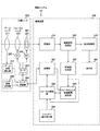
図1は、本発明の第1の実施の形態における撮像システム10の内部構成例を示すブロック図である。撮像システム10は、撮像装置100および交換レンズ200を備える。撮像システム10は、例えば、レンズを交換することが可能なデジタルスチルカメラ(例えば、デジタル一眼カメラ)により実現される。
<1. First Embodiment>
[Example of internal configuration of imaging system]
FIG. 1 is a block diagram illustrating an example of an internal configuration of an
撮像装置100は、被写体を撮像して画像データ(撮像画像)を生成し、生成された画像データを画像コンテンツ(静止画コンテンツまたは動画コンテンツ)として記録する撮像装置である。また、撮像装置100は、レンズマウント(図示せず)を介して交換レンズ200を取り付けることができる。
The
交換レンズ200は、レンズマウント(図示せず)を介して撮像装置100に取り付けられる交換レンズユニットである。交換レンズ200は、ズームレンズ211と、ズーム位置検出部212と、フォーカスレンズ221と、フォーカスレンズ駆動モータ222と、絞り231と、絞り駆動モータ232とを備える。また、交換レンズ200は、モータドライバ240と、レンズ情報保持部250と、レンズ制御部260とを備える。
The
ズームレンズ211は、電動または手動の何れかの駆動により光軸方向に移動して焦点距離を調整するレンズである。すなわち、ズームレンズ211は、撮像画像に含まれる被写体を拡大または縮小させるため、被写体に対して前後に駆動するレンズである。また、ズームレンズ211により、ズーム機能が実現される。なお、本発明の第1の実施の形態では、ユーザによる手動操作により、ズームレンズ211を駆動させる例を示す。
The
ズーム位置検出部212は、ユーザによるズーム操作により駆動されたズームレンズ211の位置を検出するものであり、検出結果をレンズ制御部260に出力する。
The zoom
フォーカスレンズ221は、フォーカスレンズ駆動モータ222の駆動により光軸方向に移動してフォーカスを調整するレンズである。すなわち、フォーカスレンズ221は、被写体に含まれる所望の対象物にピントを合わせるために使用されるレンズである。また、フォーカスレンズ221により、オートフォーカス機能が実現される。
The
フォーカスレンズ駆動モータ222は、モータドライバ240の制御に基づいて、フォーカスレンズ221を移動させるものである。
The focus
絞り231は、ズームレンズ211およびフォーカスレンズ221を通過する入射光の光量を調整するものであり、その調整後の光が撮像素子111に供給される。絞り231は、絞り駆動モータ232により駆動され、絞りの開度が調節される。
The
絞り駆動モータ232は、モータドライバ240の制御に基づいて、絞り231を駆動するものである。
The
このように交換レンズ200を構成するズームレンズ211およびフォーカスレンズ221は、被写体からの入射光を集光するレンズ群であり、これらのレンズ群により集光された光が絞り231を介して撮像素子111に入射される。
As described above, the
モータドライバ240は、レンズ制御部260の制御に基づいて、フォーカスレンズ駆動モータ222および絞り駆動モータ232を駆動するドライバである。
The
レンズ情報保持部250は、交換レンズ200を構成する各光学部材(フォーカスレンズ221、絞り231等)に関する固有の情報(レンズ情報)を保持するメモリであり、保持されている情報をレンズ制御部260に供給する。この固有の情報は、例えば、フォーカスレンズ221の位置(フォーカスが合う被写体の位置)と、焦点距離と、絞り値(F値)と、撮像倍率とを含む光学部材に関する光学部材情報(レンズ情報)である。ここで、撮像倍率は、レンズを介して入射された光により結像された像の大きさと、被写体の実際の大きさとの比率を意味する。なお、撮像倍率は、焦点距離f、絞り、フォーカスレンズ221の位置等に応じて変化する。また、レンズの種類が異なると、撮像倍率の特性も大きく変化することが多い。このため、各光学部材の状態(フォーカスレンズ221の位置等)に応じた撮像倍率が各状態に関連付けて、固有の情報としてレンズ情報保持部250に保持されている。すなわち、レンズ情報保持部250は、複数の光学部材の各状態に応じた撮像倍率を、複数の光学部材の状態毎に保持する。なお、レンズ情報保持部250は、特許請求の範囲に記載の保持部の一例である。
The lens
レンズ制御部260は、撮像装置100との間で各種情報の通信処理を行い、この通信結果に基づいて、交換レンズ200を構成する各部(フォーカスレンズ221、絞り231等)を制御するものである。すなわち、レンズ制御部260は、撮像装置100の制御部130からの制御信号に基づいて、交換レンズ200を構成する各部を制御する。また、レンズ制御部260は、撮像装置100の制御部130からの送信要求に応じて、レンズ情報保持部250に保持されているレンズ情報を制御部130に送信する。例えば、撮像装置100および交換レンズ200間の通信処理は、同期通信により行われる。なお、レンズ制御部260は、特許請求の範囲に記載の第一通信部の一例である。
The
撮像装置100は、システムバス101と、撮像素子111と、アナログ信号処理部112と、A/D(Analog/Digital)変換部113とを備える。また、撮像装置100は、デジタル信号処理部(以下では、「DSP(Digital Signal Processor)」と称する。)114と、表示部115と、記録デバイス116とを備える。また、撮像装置100は、垂直ドライバ117と、タイミングジェネレータ(以下では、「TG(Timing Generator)」と称する。)118と、操作部120と、制御部130とを備える。また、撮像装置100は、メモリ(ROM(Read Only Memory))140と、メモリ(RAM(Random Access Memory))150とを備える。また、撮像装置100は、メモリ(EEPROM(Electrically Erasable and Programmable Read Only Memory))160を備える。なお、DSP114、垂直ドライバ117、TG118、操作部120、制御部130、メモリ(ROM)140、メモリ(RAM)150およびメモリ(EEPROM)160がシステムバス101を介して相互に通信可能となるように接続されている。
The
撮像素子111は、ズームレンズ211、フォーカスレンズ221および絞り231を介して供給される光(入射光)を受光し、この入射光を電気信号に変換させる光電変換素子である。そして、撮像素子111は、変換された電気信号(アナログ信号)をアナログ信号処理部112に供給する。また、撮像素子111は、垂直ドライバ117により駆動される。なお、撮像素子111として、例えば、CCD(Charge Coupled Device)センサやCMOS(Complementary Metal Oxide Semiconductor)センサ等を用いることができる。
The
アナログ信号処理部112は、TG118により駆動され、撮像素子111から供給される電気信号(アナログ信号)についてノイズ除去処理等のアナログ処理を施すものであり、アナログ処理が施されたアナログ信号をA/D変換部113に供給する。
The analog
A/D変換部113は、TG118により駆動され、アナログ信号処理部112から供給されたアナログ信号をデジタル信号に変換するものであり、変換されたデジタル信号をDSP114に供給する。
The A /
DSP114は、制御部130の制御に基づいて、A/D変換部113から供給されるデジタル信号について、黒レベル補正、ホワイトバランス調節、γ補正等の画像処理を行うものである。そして、DSP114は、画像処理が施された画像データを、表示部115、記録デバイス116および制御部130に供給する。例えば、DSP114は、画像処理が施された画像データについて圧縮処理を施し、この圧縮処理が施された画像データ(圧縮画像データ)を記録デバイス116に供給する。また、DSP114は、記録デバイス116に記録されている圧縮画像データについて伸張処理を施し、この伸張処理が施された画像データを表示部115に供給する。なお、圧縮方式として、例えばJPEG(Joint Photographic Experts Group)方式を採用することができる。また、DSP114から供給された画像データを用いて制御部130が各制御を行う。
The
表示部115は、DSP114から供給される画像データを表示する表示装置である。表示部115は、例えば、静止画撮影モードの設定時における撮影待機状態では、DSP114により画像処理が施された画像データを撮像画像(いわゆる、スルー画像)として表示する。また、例えば、表示部115は、記録デバイス116に記録されている画像データを一覧画像として表示させ、その画像データを再生することができる。表示部115として、例えば、有機EL(Electro Luminescence)パネル、LCD(Liquid Crystal Display)等の表示パネルを用いることができる。
The
記録デバイス116は、DSP114により画像処理が施された画像データを記録する記録デバイスである。また、記録デバイス116は、記録されている画像データをDSP114に供給する。なお、記録デバイス116は、撮像装置100に内蔵するようにしてもよく、撮像装置100から着脱可能とするようにしてもよい。また、記録デバイス116として、半導体メモリ、光記録媒体、磁気ディスク、HDD(Hard Disk Drive)等の種々の記録媒体を用いることができる。なお、光記録媒体として、例えば、記録可能なDVD(Digital Versatile Disk)、記録可能なCD(Compact Disc)、ブルーレイディスク(Blu-ray Disc(登録商標))等を用いることができる。
The
垂直ドライバ117は、制御部130の制御に基づいて、撮像素子111を駆動する垂直ドライバである。
The
TG118は、制御部130から供給される基準クロックに基づいて、垂直ドライバ117、アナログ信号処理部112およびA/D変換部113の駆動制御信号を生成するものである。
The
操作部120は、各種操作を行うためのボタン、スイッチ等の操作部材を備え、ユーザからの操作入力を受け付ける操作部であり、受け付けられた操作入力の内容をシステムバス101を介して制御部130に出力する。なお、撮像装置100の外面に配置されるボタン等の操作部材以外に、表示部115上にタッチパネルを設け、ユーザからの操作入力をタッチパネルにおいて受け付けるようにしてもよい。
The
制御部130は、メモリ(ROM)140等に記憶されている各情報に基づいて、撮像装置100の各部を制御する中央演算装置である。また、制御部130は、交換レンズ200との通信制御を行い、各種情報の送受信を行う。制御部130は、例えば、露出、ホワイトバランス、フォーカス、閃光発光(図2に示す閃光発光部102)等を制御する。また、例えば、制御部130は、撮像時には、操作部120からのユーザの操作入力、DSP114からの画像データに基づいて、制御信号を生成する。そして、生成された制御信号をモータドライバ240、垂直ドライバ117、TG118、交換レンズ200等に出力し、フォーカスレンズ221や絞り231等を動作させることにより、露出、ホワイトバランス、フォーカス、閃光等の制御を行う。また、制御部130は、各処理に用いられる情報の送信要求を交換レンズ200に行う。
The
また、制御部130は、DSP114により画像処理が施された画像データを記録する場合には、操作部120からのユーザの操作入力に基づいて、DSP114に制御信号を出力する。そして、DSP114により圧縮処理が施された画像データを静止画ファイルとして記録デバイス116に記録させる。また、制御部130は、記録デバイス116に記録されている静止画ファイルを表示する場合には、操作部120からのユーザの操作入力に基づいて、DSP114に制御信号を出力する。そして、記録デバイス116に記録されている静止画ファイルに対応する画像を表示部115に表示させる。
Further, when recording image data that has been subjected to image processing by the
また、制御部130は、撮像素子111等により生成される画像信号から取得された被写体のコントラスト信号を用いてフォーカス制御(いわゆる、コントラストAF)を行う。このコントラストAFとして、コンティニュアスAFが存在する。コンティニュアスAFは、動きのある被写体に対して連続的にフォーカスを合わせ続けるオートフォーカス機能である。すなわち、コンティニュアスAFモードが設定されている場合には、ユーザがシャッターボタン121(図2に示す)を半押ししている間、被写体追従および被写体の速度予測を行い、ユーザがシャッターボタン121を深押した直後に撮影処理を実行する。これにより、ユーザの意図する画角および構図に被写体が存在し、かつ、被写体にフォーカスがあった写真(撮像画像)を記録することができる。このコンティニュアスAFにより、動く被写体に対して最適なフォーカス制御を行うことができる。なお、制御部130は、例えば、CPU(Central Processing Unit)により実現される。また、制御部130の機能構成については、図3を参照して詳細に説明する。
Further, the
メモリ(ROM)140は、制御部130が各処理を実行するための各種プログラムや各種データを記憶する不揮発性メモリである。
The memory (ROM) 140 is a non-volatile memory that stores various programs and various data for the
メモリ(RAM)150は、制御部130が動作する際に一時的に保持すべきデータや書き換え可能なデータを保持する揮発性メモリであり、例えば、制御部130が動作する際に作業用のメモリとして用いられる。
The memory (RAM) 150 is a volatile memory that holds data that should be temporarily stored or rewritable data when the
メモリ(EEPROM)160は、撮像装置100が電源オフの間もデータを保持するメモリであり、各種設定条件等が記録される。
A memory (EEPROM) 160 is a memory that retains data even when the
[撮像システムの外観構成例]
図2は、本発明の実施の第1の形態における撮像システム10の外観構成例を示す図である。図2(a)は、撮像システム10の外観を示す正面図であり、図2(b)は、撮像システム10の外観を示す背面図であり、図2(c)は、撮像システム10の外観を示す上面図である。
[External configuration example of imaging system]
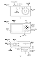
FIG. 2 is a diagram illustrating an external configuration example of the
撮像装置100は、閃光発光部102と、撮像素子111と、表示部115と、シャッターボタン121と、モードダイヤル122と、上下左右操作ボタン123と、決定ボタン124と、キャンセルボタン125と、電源スイッチ126とを備える。また、交換レンズ200は、ズームレンズ211と、フォーカスレンズ221と、絞り231とを備える。なお、シャッターボタン121、モードダイヤル122、上下左右操作ボタン123、決定ボタン124、キャンセルボタン125および電源スイッチ126は、図1に示す操作部120に対応する。また、撮像素子111、表示部115、ズームレンズ211、フォーカスレンズ221および絞り231は、図1に示す同一名称の各部に対応するため、ここでの詳細な説明を省略する。なお、ズームレンズ211、フォーカスレンズ221および絞り231は、交換レンズ200に内蔵されているものであり、撮像素子111は、撮像装置100に内蔵されているものであるため、これらを図2(c)では点線で示す。
The
図2では、撮像装置100の外側面に設けられている上下左右操作ボタン123、決定ボタン124等の操作部材を用いて、表示部115に表示される画像やボタン等の選択操作(例えば、ボタンの押下操作)を行う撮像システム10を例にして示す。
In FIG. 2, selection operations (for example, buttons) for images and buttons displayed on the
閃光発光部102は、制御部130(図1に示す)の制御に基づいて、被写体への光線を照射させ、被写体からの光(反射光)を増加させるものである。これにより、周囲の照度が低い状況においても撮像を可能とする。
The flash
シャッターボタン121は、シャッター操作を行うための操作部材であり、ユーザにより全押しまたは半押し操作が行われる。例えば、シャッターボタン121が半押しされた場合には、撮像に最適なフォーカス制御が行われる。また、シャッターボタン121が全押しされた場合には、撮像に最適なフォーカス制御が行われ、この全押しの際における画像データが記録デバイス116に記録される。
The
モードダイヤル122は、各モードを設定するためのダイヤルである。例えば、通常のAFモード、コンティニュアスAFモード、記録デバイス116に記録されている画像を表示させるための画像表示モード等がモードダイヤル122の操作により設定される。
The
上下左右操作ボタン123は、表示部115に表示されるボタンや画像等の項目を選択する場合に用いられる操作ボタンであり、押下された部分に応じて現在選択されている項目が上下左右に移動する。
The up / down / left /
決定ボタン124は、表示部115に表示されている各項目の選択状態を確定する場合に用いられるボタンである。キャンセルボタン125は、表示部115に表示されている各項目の選択状態が確定されている場合に、この確定を解除するために用いられるボタンである。電源スイッチ126は、撮像装置100の電源のON/OFFを切り替えるスイッチである。
The
また、撮像システム10においては、ユーザの手動操作によりズーム操作が行われる。このズーム操作は、例えば、交換レンズ200の所定部分をユーザが手で握った状態で行われる。例えば、ユーザの手動操作によりズーム操作が行われると、この手動操作に応じてズーム機能が制御され、撮像画像に含まれる被写体を拡大または縮小させることができる。
In the
[撮像装置の機能構成例]
図3は、本発明の第1の実施の形態における撮像装置100の機能構成例を示すブロック図である。図3では、説明の容易のため、撮像装置100の機能構成とともに、図1に示す交換レンズ200の内部構成を示す。
[Functional configuration example of imaging device]
FIG. 3 is a block diagram illustrating a functional configuration example of the
撮像装置100は、撮像部310と、画像信号処理部320と、評価値生成部330と、フォーカスレンズ移動範囲設定部340と、フォーカス制御部350とを備える。また、撮像装置100は、通信部360と、表示制御部370と、表示部380と、シャッター操作受付部390とを備える。なお、撮像部310は、例えば、図1に示す撮像素子111、アナログ信号処理部112およびA/D変換部113に対応する。また、画像信号処理部320は、例えば、図1に示すDSP114に対応する。また、評価値生成部330、フォーカスレンズ移動範囲設定部340、フォーカス制御部350および通信部360は、例えば、図1に示す制御部130に対応する。また、表示制御部370は、例えば、図1に示すDSP114に対応する。また、表示部380は、例えば、図1に示す表示部115に対応する。また、シャッター操作受付部390は、例えば、図1に示す操作部120に対応する。
The
撮像部310は、フォーカスレンズ221を介して入射される被写体からの入射光を変換して撮像画像(画像信号)を生成するものであり、生成された画像信号(電気信号)を画像信号処理部320に供給する。なお、図3では、撮像部310により生成された撮像画像(画像データ)を記録する記録処理に関する機能構成については、図示およびその説明を省略する。
The
画像信号処理部320は、撮像部310から出力された画像信号に対して各種の信号処理を施すものであり、信号処理が施された画像信号を評価値生成部330および表示制御部370に出力する。
The image
評価値生成部330は、画像信号処理部320から出力された画像信号からAF評価値(コントラスト信号)を生成するものであり、生成されたAF評価値をフォーカスレンズ移動範囲設定部340およびフォーカス制御部350に出力する。すなわち、評価値生成部330は、画像信号処理部320から出力された画像信号に対応する撮像画像に含まれる特定領域(AF領域)において、このAF領域内の画像の空間周波数の高周波成分を抽出する。そして、評価値生成部330は、その抽出された高周波成分の輝度差分(AF評価値)を生成する。このように生成されたAF評価値に基づいて合焦位置が検出される。
The evaluation
フォーカスレンズ移動範囲設定部340は、フォーカス制御部350がフォーカス制御を行うためのフォーカスレンズ移動範囲を設定するものであり、設定されたフォーカスレンズ移動範囲をフォーカス制御部350に出力する。具体的には、フォーカスレンズ移動範囲設定部340は、フォーカスレンズ移動範囲を設定する際に用いられる情報(撮像倍率等のレンズ情報)を通信部360を介して交換レンズ200から取得する。そして、フォーカスレンズ移動範囲設定部340は、その取得された各情報と、評価値生成部330から出力されたAF評価値と、フォーカス制御部350からのフォーカス制御に関する情報とに基づいてフォーカスレンズ移動範囲を設定する。
The focus lens movement
例えば、フォーカスレンズ221の位置(注目被写体に合焦していると想定される位置)に対応する撮像倍率を基準とする。この場合に、フォーカスレンズ移動範囲設定部340は、その基準からの撮像倍率の変化率が一定範囲内となる撮像倍率に対応するフォーカスレンズ221の位置に係る範囲をフォーカスレンズ移動範囲として設定する。例えば、フォーカスレンズ移動範囲設定部340は、その変化率が一定範囲内となる撮像倍率に対応するフォーカスレンズ221の位置のうち、その基準に係るフォーカスレンズ221の位置からの距離が至近側で最も長い位置を特定する。また、フォーカスレンズ移動範囲設定部340は、その距離が無限側で最も長い位置を特定する。そして、フォーカスレンズ移動範囲設定部340は、その2つの位置により特定される範囲をフォーカスレンズ移動範囲とすることができる。すなわち、フォーカスレンズ移動範囲設定部340は、フォーカスレンズ221の位置に対応する撮像倍率を基準として、この基準からの撮像倍率の変化率に基づいて、フォーカスレンズ移動範囲を設定する。
For example, the imaging magnification corresponding to the position of the focus lens 221 (position assumed to be focused on the subject of interest) is used as a reference. In this case, the focus lens movement
なお、フォーカスレンズ移動範囲設定部340は、光軸方向に対する被写体の移動速度を算出し、算出された移動速度が一定値を基準として小さい場合に、その撮像倍率に基づくフォーカスレンズ移動範囲を設定する。また、フォーカスレンズ移動範囲設定部340は、コンティニュアスAFモードが設定されている場合において、スルー画像が表示部380に表示されている場合に、その撮像倍率に基づくフォーカスレンズ移動範囲を設定する。
The focus lens movement
ここで、その設定されたフォーカスレンズ移動範囲が、フォーカス制御部350によるフォーカス制御の際に必要となる範囲(AF最小範囲)を満たしていないことも想定される。この場合には、フォーカスレンズ移動範囲設定部340は、フォーカスレンズ移動範囲としてそのAF最小範囲を新たに設定する。
Here, it is also assumed that the set focus lens movement range does not satisfy the range (AF minimum range) necessary for focus control by the
また、フォーカスレンズ移動範囲設定部340は、その基準に係るフォーカスレンズ221の位置に対応する焦点深度に基づいて、フォーカスレンズ移動範囲を算出する。そして、フォーカスレンズ移動範囲設定部340は、算出された焦点深度に基づくフォーカスレンズ移動範囲と、撮像倍率に基づくフォーカスレンズ移動範囲とを比較する。この比較の結果、フォーカスレンズ移動範囲設定部340は、範囲が狭いフォーカスレンズ移動範囲を選択し、この選択されたフォーカスレンズ移動範囲を設定することができる。なお、フォーカスレンズ移動範囲設定部340は、特許請求の範囲に記載の設定部および算出部の一例である。
Further, the focus lens movement
フォーカス制御部350は、交換レンズ200との通信制御を行い、この通信により通信部360を介して取得された各情報と、評価値生成部330から出力されたAF評価値とに基づいて、フォーカス制御を行うものである。すなわち、フォーカス制御部350は、フォーカスレンズ移動範囲設定部340により設定されたフォーカスレンズ移動範囲において、フォーカスレンズ221を移動させることによりフォーカス制御を行う。なお、フォーカス制御部350は、例えば、シャッターボタン121の半押し操作または全押し操作が行われた際に、フォーカス制御を行う。
The
通信部360は、フォーカス制御部350の制御に基づいて、レンズ制御部260との間で通信を行うものである。例えば、通信部360は、フォーカス制御部350の制御に基づいて、レンズ制御部260との間で同期通信を行う。なお、通信部360は、特許請求の範囲に記載の第二通信部の一例である。
The
表示制御部370は、画像信号処理部320により画像信号処理が施された撮像画像をスルー画像として表示部380に順次表示させるものである。例えば、表示制御部370は、静止画撮影モードの設定時における撮影待機状態において、スルー画像を表示部380に順次表示させる。
The
表示部380は、表示制御部370から供給された撮像画像をスルー画像として表示する表示部である。
The
シャッター操作受付部390は、ユーザにより行われるシャッターボタン121の押下操作を受け付ける操作受付部であり、受け付けられた操作内容をフォーカス制御部350に出力する。具体的には、シャッターボタン121の半押し操作または全押し操作が行われた場合には、フォーカス制御部350により最適なフォーカス制御が行われる。また、シャッターボタン121の全押し操作が行われた場合には、そのフォーカス制御が行われ、この全押し操作の際に撮像部310により生成された撮像画像が記録デバイス116(図1に示す)に記録される。
The shutter
[コンティニュアスAFモード設定時におけるフォーカスレンズの遷移例]
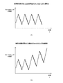
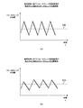
図4は、本発明の第1の実施の形態における撮像装置100においてコンティニュアスAFモードが設定されている場合におけるフォーカスレンズ221の遷移例を示す図である。図4(a)には、撮像装置100と、被写体との距離(被写体距離)が略一定である場合におけるフォーカスレンズ221の遷移例を示す。図4(b)には、被写体距離が変化する場合におけるフォーカスレンズ221の遷移例を示す。
[Focus lens transition example when continuous AF mode is set]
FIG. 4 is a diagram illustrating a transition example of the
なお、図4(a)および(b)では、縦軸をフォーカスレンズ221の位置(光軸方向における位置)を示す軸とし、横軸を時間軸として、フォーカスレンズ221の遷移例を示す。また、図4(a)および(b)では、AF評価値を取得する際におけるフォーカスレンズ221の遷移を実線で示し、AF処理の開始点に移動する際におけるフォーカスレンズ221の遷移を点線で示す。
4A and 4B show transition examples of the
ここで、コントラストAFの特性について説明する。コントラストAFは、撮像画像に含まれる特定領域(AF領域)において、このAF領域内の画像の空間周波数の高周波成分を抽出し、この高周波成分の輝度差分(AF評価値)に基づいて合焦位置を検出する方法である。すなわち、その抽出された高周波成分の輝度差分が最も大きくなる位置にフォーカスレンズを移動させることにより、フォーカスが合った撮像画像を生成することができる。 Here, the characteristics of contrast AF will be described. In contrast AF, in a specific area (AF area) included in a captured image, a high-frequency component of the spatial frequency of the image in the AF area is extracted, and a focus position is based on a luminance difference (AF evaluation value) of the high-frequency component. It is a method of detecting. That is, the focused image can be generated by moving the focus lens to a position where the luminance difference of the extracted high-frequency component is the largest.
また、コントラストAFを撮像システム10に用いることにより、構成部品を少なくすることができ、小型化および低コスト化を実現することができる。ここで、交換レンズ方式の撮像システムでは、交換レンズおよび撮像装置(カメラ本体)を組み合わせた際におけるフランジバックの長さの誤差を起因としてAF精度が劣化することが想定される。しかしながら、コントラストAFを用いることにより、フランジバックの長さの誤差を起因とするAF精度の劣化を抑えることができる。
Further, by using the contrast AF in the
次に、コントラストAFを用いた撮像装置において、動く被写体に対するAF処理を行う場合を想定する。コントラストAFを用いた撮像装置では、被写体(注目被写体)の位置を中心にしてその前後の所定範囲(フォーカスレンズ移動範囲)内においてフォーカスレンズを移動させる必要がある。例えば、図4(a)に示すように、被写体距離が略一定である場合には、フォーカスレンズを移動させる範囲(フォーカスレンズ移動範囲)を略一定としてAF処理を行うことができる。 Next, it is assumed that AF processing is performed on a moving subject in an imaging apparatus using contrast AF. In an imaging apparatus using contrast AF, it is necessary to move the focus lens within a predetermined range (focus lens movement range) before and after the position of the subject (target subject). For example, as shown in FIG. 4A, when the subject distance is substantially constant, the AF process can be performed with the range in which the focus lens is moved (focus lens movement range) being substantially constant.
しかしながら、動く被写体に対するAF処理(コンティニュアスAF)では、変化する被写体の位置を示す輝度差分(AF評価値)の最大値を追い続ける必要がある。このため、シャッターボタンの半押し操作が行われている間、フォーカスレンズを移動させ続ける必要がある。例えば、図4(b)に示すように、被写体距離が変化する場合には、被写体が光軸方向に移動しているため、この移動に合わせてフォーカスレンズ移動範囲を変化させながらAF処理を行う必要がある。 However, in the AF process (continuous AF) for a moving subject, it is necessary to continue to follow the maximum value of the luminance difference (AF evaluation value) indicating the position of the subject that changes. For this reason, it is necessary to continue to move the focus lens while the shutter button is half-pressed. For example, as shown in FIG. 4B, when the subject distance changes, since the subject moves in the optical axis direction, AF processing is performed while changing the focus lens moving range in accordance with this movement. There is a need.
ここで、フォーカスレンズ移動範囲を設定する場合には、動いている被写体に対してその被写体の移動速度の検出誤差を考慮しながら確実に被写体を捕捉することが可能なフォーカスレンズ移動範囲を設定することが好ましい。ただし、被写体が静止している場合には、フォーカスレンズを動かさないということも考えられる。 Here, when the focus lens moving range is set, the focus lens moving range is set so that the subject can be reliably captured while taking into account the detection error of the moving speed of the subject with respect to the moving subject. It is preferable. However, it is also conceivable that the focus lens is not moved when the subject is stationary.
しかしながら、コントラストAFにおいて、フォーカスレンズを完全に停止させると、シャッターボタンの全押し時の時点ではフォーカスレンズを前後に移動させてAF処理を行う必要があるため、レスポンスが極端に悪くなるおそれがある。また、動体の移動速度を正確に予測することは困難であると想定される。そこで、被写体の速度が分からない場合でも、所定のフォーカスレンズ移動範囲でAF処理を行い続けることが好ましい。 However, in contrast AF, if the focus lens is completely stopped, it is necessary to perform AF processing by moving the focus lens back and forth at the time when the shutter button is fully pressed, which may cause extremely poor response. . Moreover, it is assumed that it is difficult to accurately predict the moving speed of the moving object. Therefore, it is preferable to continue the AF process within a predetermined focus lens movement range even when the speed of the subject is unknown.
ここで、表示部380に表示されるスルー画像の視認性について説明する。上述したように、被写体の速度が分からない場合でも、所定のフォーカスレンズ移動範囲でフォーカスレンズを移動させることが好ましいが、フォーカスレンズを移動させる場合には、フォーカスレンズの移動に応じて撮像倍率が変更される。このため、この変更に応じて表示部380に表示されるスルー画像が拡大または縮小される。
Here, the visibility of the through image displayed on the
例えば、表示部380に表示されるスルー画像の拡大または縮小が微小である場合には、スルー画像に与える影響が少ない。しかしながら、撮像倍率の変化率が比較的大きい場合には、スルー画像の拡大または縮小が大きくなり、ユーザが被写体を確認する際に、スルー画像を見難くなるおそれがある。そこで、本発明の第1の実施の形態では、一定条件を満たす場合には、撮像倍率に基づいてフォーカスレンズ移動範囲を設定することにより、表示部380に表示されるスルー画像の視認性を向上させ、長時間見ることの不快感を低減させる。
For example, when the through image displayed on the
[フォーカスレンズの位置とこの位置におけるAF評価値との関係例]
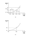
図5は、本発明の第1の実施の形態におけるフォーカスレンズ221の位置とこの位置において算出されるAF評価値(コントラスト)との関係例を示す図である。図5(a)および(b)では、縦軸をAF評価値(コントラスト)を示す軸とし、横軸をフォーカスレンズ221の位置を示す軸とする。図5(a)に示すように、例えば、合焦となる被写体が存在する場合には、フォーカスレンズ221の位置に対するAF評価値は曲線K1を描く。
[Example of relationship between focus lens position and AF evaluation value at this position]
FIG. 5 is a diagram showing a relationship example between the position of the
図5(a)に示す例では、曲線K1におけるピーク位置P1が、評価値生成部330により生成された撮像画像のコントラスト値が最大の位置となる。すなわち、ピーク位置P1が合焦位置(ジャスピン)となる。
In the example shown in FIG. 5A, the peak position P1 in the curve K1 is the position where the contrast value of the captured image generated by the evaluation
ここで、AF処理について説明する。AF処理は、シャッターボタン121の半押し操作または全押し操作が行われた場合に行われる。このAF処理において、例えば、図4(a)および(b)に示す点線(コントラスト情報の取得を開始する位置への移動)および実線(コントラスト情報の取得動作)を組み合わせた1つの動作(1回のAF処理)が繰り返し行われる。この1回のAF処理を実行する毎に、レンズから被写体までの距離(被写体距離)を捕えることが可能である。すなわち、被写体距離をaとし、レンズから撮像素子111に結像される像までの距離をbとし、レンズの焦点距離をfとする場合には、次の式1が成り立つ。
(1/a)+(1/b)=1/f … 式1
Here, the AF process will be described. The AF process is performed when the
(1 / a) + (1 / b) = 1 / f Equation 1
この式1により、被写体距離a=1/((1/f)−(1/b))を求めることができる。また、AF処理を繰り返すことにより、被写体距離の変化を取得することができる。このようして取得された被写体距離の変化(距離変化情報)に基づいて、被写体の速度(光軸方向における速度)を算出することができる(被写体速度予測処理)。具体的には、被写体距離の変化量(被写体の移動量)をDC1とし、被写体距離が取得された時刻の間隔をtとする場合に、各時刻における被写体の速度(被写体速度V)は、次の式2により求めることができる。
V=DC1/t … 式2
From this equation 1, the subject distance a = 1 / ((1 / f) − (1 / b)) can be obtained. Further, the subject distance change can be acquired by repeating the AF process. Based on the change in the subject distance (distance change information) acquired in this way, the subject speed (speed in the optical axis direction) can be calculated (subject speed prediction process). Specifically, when the amount of change in the subject distance (the amount of movement of the subject) is DC1, and the time interval at which the subject distance is acquired is t, the subject speed (subject speed V) at each time is It can obtain | require by the formula 2.
V = DC1 / t Equation 2
すなわち、被写体距離の変化量DC1を、被写体距離が取得された時刻の間隔tで除算することにより被写体速度Vを算出することができる。なお、シャッターボタン121が半押しされている間は、AF処理が繰り返し行われる。
That is, the subject speed V can be calculated by dividing the subject distance change amount DC1 by the time interval t when the subject distance is acquired. Note that the AF process is repeated while the
図5(b)には、AF処理において、フォーカスレンズ221を移動させる範囲の一例(フォーカスレンズ移動範囲AFR1)を示す。フォーカスレンズ移動範囲AFR1は、焦点深度φに基づいて算出されたフォーカスレンズ移動範囲である。
FIG. 5B shows an example of a range in which the
ここで、フォーカスレンズ移動範囲AFR1を用いたAF処理が行われる場合は、被写体速度Vが算出されなかった場合、被写体速度Vが閾値thV未満である場合、または、前回のAF処理において被写体の捕捉に失敗していない場合である。すなわち、コンティニュアスAFモードが設定されている場合において、一定条件を満たす場合(被写体の移動速度が遅い場合や被写体が停止している場合)には、フォーカスレンズ移動範囲AFR1を用いたAF処理が行われる。なお、閾値thVは、例えば、人が歩く速度と同程度の値とすることができる。例えば、閾値thVとして、0.5乃至1.0m/sを用いることができる。 Here, when the AF process using the focus lens moving range AFR1 is performed, the subject speed V is not calculated, the subject speed V is less than the threshold thV, or the subject is captured in the previous AF process. It is a case where it has not failed. That is, when the continuous AF mode is set and the certain condition is satisfied (when the moving speed of the subject is slow or the subject is stopped), the AF processing using the focus lens moving range AFR1 Is done. Note that the threshold thV can be set to a value comparable to the speed at which a person walks, for example. For example, 0.5 to 1.0 m / s can be used as the threshold thV.
例えば、前回に比較的狭いフォーカスレンズ移動範囲が設定された場合には、このフォーカスレンズ移動範囲を用いて行われたAF処理において被写体の捕捉に失敗することも想定される。このため、前回のAF処理において被写体の捕捉に失敗した場合には、フォーカスレンズ移動範囲を拡大させてAF処理を行うことが好ましい。例えば、前回のAF処理の結果がローコントラストであった場合には、その時点においてフォーカスレンズが移動可能な範囲の全てをフォーカスレンズ移動範囲とする。一方、至近端側がコントラストのピークであった場合には、その端点から至近側に所定量だけ広げた範囲を今回のフォーカスレンズ移動範囲とする。また、無限端がコントラストのピークであった場合には、その端点から至近側に所定量だけ広げた範囲を今回のフォーカスレンズ移動範囲とする。この場合に、広げ量は固定量とするようにしてもよく、低周波領域のコントラスト情報と高周波領域のコントラスト情報の比を用いて、その比等に応じて調節された量を広げ量とするようにしてもよい。 For example, when a relatively narrow focus lens movement range is set last time, it is also assumed that the subject capture may fail in the AF process performed using this focus lens movement range. For this reason, when the subject has failed to be captured in the previous AF process, it is preferable to perform the AF process by expanding the focus lens movement range. For example, if the result of the previous AF processing is low contrast, the entire range in which the focus lens can move at that time is set as the focus lens movement range. On the other hand, when the close end side has a contrast peak, a range widened by a predetermined amount from the end point to the close side is set as the focus lens moving range this time. If the infinite end is a contrast peak, a range expanded by a predetermined amount from the end point to the closest side is set as the focus lens moving range this time. In this case, the amount of expansion may be a fixed amount, and the amount adjusted according to the ratio or the like is set as the amount of expansion using the ratio between the contrast information in the low frequency region and the contrast information in the high frequency region. You may do it.
次に、フォーカスレンズ移動範囲AFR1の算出方法について説明する。 Next, a method for calculating the focus lens movement range AFR1 will be described.
最初に、AF処理の開始時に、フォーカス制御部350が、交換レンズ200のレンズ制御部260との間で通信部360を介して通信処理を行う。この通信により、レンズ情報保持部250に保持されているレンズ情報を、フォーカスレンズ移動範囲設定部340およびフォーカス制御部350が取得する。ここで、レンズ情報保持部250に保持されているレンズ情報は、フォーカスレンズ221の位置(フォーカスが合う被写体の位置)と、焦点距離と、絞り値(F値)と、撮像倍率とを含む。なお、撮像倍率は、焦点距離f、フォーカスレンズ221の位置等に応じて変化する。このため、各光学部材の状態(フォーカスレンズ221の位置等)に応じた撮像倍率が各状態に関連付けて、レンズ情報としてレンズ情報保持部250に保持されている。
First, at the start of AF processing, the
なお、レンズ制御部260は、モータドライバ240から取得される焦点距離f、フォーカスレンズ221の位置等のレンズ情報に基づいて、これらの各レンズ情報に対応する撮像倍率をレンズ情報保持部250から取得する。そして、レンズ制御部260は、取得されたレンズ情報(撮像倍率を含む)を、フォーカスレンズ移動範囲設定部340およびフォーカス制御部350に通信部360を介して送信する。
The
続いて、フォーカスレンズ移動範囲設定部340が、取得されたレンズ情報に基づいて、レンズの焦点深度φを算出する。ここで、レンズの焦点深度φは、次の式3を用いて算出される。
φ=F×δ … 式3
ここで、Fは、絞り値(F値)であり、δは、撮像素子111の許容錯乱円を示す値である。
Subsequently, the focus lens moving
φ = F × δ Equation 3
Here, F is an aperture value (F value), and δ is a value indicating an allowable circle of confusion of the
続いて、フォーカスレンズ移動範囲設定部340が、算出された焦点深度φに基づいてフォーカスレンズ移動範囲AFR1を算出する。このフォーカスレンズ移動範囲AFR1は、コントラストAFにおいて、移動する被写体を捕捉するために十分だと仮定される係数と、算出された焦点深度φとに基づいて算出される。具体的には、フォーカスレンズ移動範囲設定部340が、次の式4および式5を用いて、至近側移動範囲R1Nおよび無限側移動範囲R1Fを算出する。ここで、至近側移動範囲R1Nおよび無限側移動範囲R1Fは、被写体が存在すると想定される位置を基準として、至近側および無限側にそれぞれ設定される範囲である。
R1N=KN×φ … 式4
R1F=KF×φ … 式5
ここで、至近側係数KNおよび無限側係数KFは、コントラストAFにおいて、移動する被写体を捕捉するために十分であると仮定される係数である。例えば、至近側係数KNおよび無限側係数KFとして、1乃至20の範囲内の値を用いることができる。なお、至近側係数KNおよび無限側係数KFを同一の値とするようにしてもよく、それぞれを異なる値とするようにしてもよい。また、至近側係数KNおよび無限側係数KFは、例えば、撮像装置100が固有値として保持する(例えば、メモリ(ROM)140に保持)。
Subsequently, the focus lens movement
R1 N = K N × φ Equation 4
R1 F = K F × φ Equation 5
Here, the near side coefficient K N and the infinite side coefficient K F are coefficients that are assumed to be sufficient for capturing a moving subject in contrast AF. For example, values in the range of 1 to 20 can be used as the near side coefficient K N and the infinite side coefficient K F. Note that the near side coefficient K N and the infinite side coefficient K F may be set to the same value, or may be set to different values. Further, the near side coefficient K N and the infinite side coefficient K F are, for example, held as eigenvalues (for example, held in the memory (ROM) 140).
このように算出された至近側移動範囲R1Nおよび無限側移動範囲R1Fを用いて、フォーカスレンズ移動範囲設定部340が、フォーカスレンズ移動範囲AFR1を算出する。具体的には、フォーカスレンズ移動範囲AFR1は、次の式6により求めることができる。
Sp+R1N>AFR1>Sp−R1F … 式6
ここで、Spは、注目被写体に合焦すると想定される位置(フォーカスレンズ221の位置)を示す。なお、本発明の第1の実施の形態では、フォーカスレンズ221の位置は、値が大きいほど至近側とする。
The focus lens movement
Sp + R1 N >AFR1> Sp-R1 F Formula 6
Here, Sp indicates a position (position of the focus lens 221) assumed to be focused on the subject of interest. In the first embodiment of the present invention, the position of the
[フォーカスレンズの位置と撮像倍率との関係例]
図6は、本発明の第1の実施の形態におけるフォーカスレンズ221の位置とこの位置に対応する撮像倍率との関係例を示す図である。図6(a)および(b)では、縦軸を撮像倍率(β)を示す軸とし、横軸をフォーカスレンズ221の位置を示す軸とする。なお、原点は、注目被写体に合焦すると想定される位置(フォーカスレンズ221の位置)と、この位置に対応する撮像倍率とを示す。なお、図6(a)および(b)に示す横軸では、原点から矢印方向への移動は至近側への移動を意味するものとする。
[Example of relationship between focus lens position and imaging magnification]
FIG. 6 is a diagram illustrating a relationship example between the position of the
図6(a)に示すように、フォーカスレンズ221の移動に応じて、撮像倍率が変化する。例えば、フォーカスレンズ221の位置がFC11からFC12に変化した場合における撮像倍率の変化量をβ11とし、フォーカスレンズ221の位置がFC13からFC14に変化した場合における撮像倍率の変化量をβ12とする。なお、FC11からFC12への変化量と、FC13からFC14への変化量とが同一(変化量H)であるものとする。この場合には、図6(a)に示すように、位置FC13からFC14への変化に対応する撮像倍率の変化量β12が、位置FC11からFC12への変化に対応する撮像倍率の変化量β11よりも大きくなる。すなわち、フォーカスレンズ221の移動距離が大きくなるほど、その移動量に対する撮像倍率の変化量が大きくなる。また、フォーカスレンズ221の移動量に対する撮像倍率が変化すると、この変化に応じて、撮像部310により生成される撮像画像の撮像倍率が変更される。すなわち、フォーカスレンズ221の移動量に対する撮像倍率の変化量が大きくなると、撮像部310により生成される撮像画像の撮像倍率の変化量も大きくなる。このように撮像倍率の変化量が大きくなると、例えば、撮影待機中において、表示部380に表示されるスルー画像の倍率の変化量も大きくなり、スルー画像が見難くなることが想定される。この場合には、撮影待機中において、表示部380に表示される撮像画像に含まれる被写体をユーザが確認することが困難となり、ユーザが不快に感じるおそれがある。
As shown in FIG. 6A, the imaging magnification changes according to the movement of the
そこで、例えば、図5に示す例で算出されたフォーカスレンズ移動範囲AFR1が比較的大きい場合には、撮像倍率の変化量も大きくなるため、撮像倍率の変化量を抑えるようにフォーカスレンズ移動範囲を制限することが好ましい。これにより、撮影待機中において、表示部380に表示される撮像画像に含まれる被写体をユーザが確認することが容易となり、ユーザの視認性を向上させることができる。
Therefore, for example, when the focus lens movement range AFR1 calculated in the example shown in FIG. 5 is relatively large, the amount of change in the imaging magnification also increases. Therefore, the focus lens movement range is set to suppress the amount of change in the imaging magnification. It is preferable to limit. This makes it easy for the user to check the subject included in the captured image displayed on the
そこで、本発明の第1の実施の形態では、撮像倍率に基づいてフォーカスレンズ移動範囲AFR2を算出する。そして、この算出されたフォーカスレンズ移動範囲AFR2と、フォーカスレンズ移動範囲AFR1とを比較して、この比較結果に基づいて、フォーカスレンズ移動範囲AFRを決定する。すなわち、フォーカスレンズ移動範囲AFR2およびフォーカスレンズ移動範囲AFR1を比較した結果、狭い方の範囲をフォーカスレンズ移動範囲AFRとして設定する。以下では、図6(b)を参照して、このように用いられるフォーカスレンズ移動範囲AFR2の算出方法について説明する。 Therefore, in the first embodiment of the present invention, the focus lens movement range AFR2 is calculated based on the imaging magnification. Then, the calculated focus lens movement range AFR2 is compared with the focus lens movement range AFR1, and the focus lens movement range AFR is determined based on the comparison result. That is, as a result of comparing the focus lens movement range AFR2 and the focus lens movement range AFR1, the narrower range is set as the focus lens movement range AFR. Hereinafter, a calculation method of the focus lens movement range AFR2 used in this way will be described with reference to FIG.
フォーカスレンズ221の位置FC1における撮像倍率をβ1とし、フォーカスレンズ221の位置FCxにおける撮像倍率をβxとする。この場合における撮像倍率の変化率RC1は、次の式7により求めることができる。
RC1=|β1−βx|/β1 … 式7
なお、撮像倍率β1およびβxは、フォーカス制御部350からの送信要求に応じてレンズ制御部260から送信される。
The imaging magnification at the position FC1 of the
RC1 = | β1-βx | / β1 Equation 7
The imaging magnifications β1 and βx are transmitted from the
また、位置FC1からの単調増加または単調減少による変化により、次の式8を満たす最小のβxを求める。
RC1<Thb … 式8
ここで、Thbは、レンズに依存せず一意に規定される閾値であり、例えば、0.1乃至2.0(%)の値とすることができる。すなわち、変化率RC1の演算時における誤差が想定されるため、閾値Thbは比較的小さい値とすることが好ましい。
Further, the minimum βx that satisfies the following Expression 8 is obtained by a change due to monotonous increase or monotonic decrease from the position FC1.
RC1 <Thb ... Formula 8
Here, Thb is a threshold value uniquely defined without depending on the lens, and can be set to a value of 0.1 to 2.0 (%), for example. That is, since an error at the time of calculating the change rate RC1 is assumed, the threshold value Thb is preferably set to a relatively small value.
また、式8により求められたβxに対応するフォーカスレンズ221の位置をFCxとする場合における撮像倍率に基づく移動範囲をMaglimとする。この移動範囲Maglimは、次の式9を用いて求めることができる。
Maglim=|FC1−FCx| … 式9
Further, a movement range based on the imaging magnification when the position of the
Mag lim = | FC1-FCx |
また、R2N=MaglimN(至近方向への撮像倍率に基づく移動範囲)、R2F=MaglimF(無限方向への撮像倍率に基づく移動範囲)とする。この場合には、フォーカスレンズ移動範囲AFR2は、次の式10により求めることができる。
Sp+R2N>AFR2>Sp−R2F … 式10
Further, R2 N = Mag limN (movement range based on the imaging magnification in the closest direction) and R2 F = Mag limF (movement range based on the imaging magnification in the infinite direction). In this case, the focus lens movement range AFR2 can be obtained by the following equation (10).
Sp + R2 N>AFR2> Sp -R2 F ...
このように、フォーカスレンズ移動範囲設定部340が、撮像倍率に基づいてフォーカスレンズ移動範囲AFR2を算出する。
In this way, the focus lens movement
ここで、移動範囲Maglimは、至近側および無限側で異なる。このため、式10に示すように、至近側および無限側のそれぞれの移動範囲Maglimを用いてフォーカスレンズ移動範囲AFR2を算出する以外に、至近側および無限側のうちの最大値のみを代表値として用いるようにしてもよい。すなわち、至近側および無限側のそれぞれの移動範囲Maglimの最大値を代表値RF1とし、この代表値RF1を用いてフォーカスレンズ移動範囲AFR2(Sp+RF1>AFR2>Sp−RF1)を算出するようにしてもよい。
Here, the movement range Mag lim is different between the closest side and the infinite side. Therefore, as shown in
また、照度が低い場合等のように、比較的大きなフォーカスレンズ移動範囲が必要となる場合には、R2N=R1N、R2F=R1Fとして、AF処理の追従性能の悪化を防止するようにしてもよい。 Also, when a relatively large focus lens movement range is required, such as when the illuminance is low, R2 N = R1 N and R2 F = R1 F are set to prevent the tracking performance of the AF process from deteriorating. It may be.
続いて、フォーカスレンズ移動範囲設定部340は、算出されたフォーカスレンズ移動範囲AFR1およびAFR2を比較して、この比較結果に基づいて、フォーカスレンズ移動範囲を設定する。すなわち、フォーカスレンズ移動範囲設定部340は、算出されたフォーカスレンズ移動範囲AFR1およびAFR2を比較した結果、小さい範囲をフォーカスレンズ移動範囲として設定する。なお、この例では、AFR1およびAFR2の比較によりフォーカスレンズ移動範囲を設定する例を示すが、至近側毎および無限側毎に比較を行い、この比較結果に基づいて、至近側および無限側のそれぞれにおける小さい範囲を選択するようにしてもよい。
Subsequently, the focus lens movement
ここで、フォーカスレンズ移動範囲としてAFR2が決定された場合には、コントラストAFを実行するために最低限必要な移動範囲(AF最小範囲)Rminを満たしていないことも想定される。コントラストAFでは、フォーカスが合っている付近では、コントラストの変化が緩やかとなり過ぎるため、フォーカスが合っているのか、ローコントラスト被写体であるのかを判断することができないことがある。そこで、この判断を可能とするため、最低限必要な移動範囲RminNおよびRminFだけは、フォーカスレンズを移動させることが必要となる。このため、R2NがRminNよりも小さい場合、または、R2FがRminFよりも小さい場合には、次の式11を用いて求められるフォーカスレンズ移動範囲AFR3を設定する(AF最小範囲保障処理)。
Sp+RminN>AFR3>Ap−RminF … 式11
なお、最低限必要な移動範囲RminNおよびRminFは、例えば、撮像装置100が固有値として保持する(例えば、メモリ(ROM)140に保持)。
Here, when AFR2 is determined as the focus lens movement range, it is also assumed that the minimum movement range (AF minimum range) Rmin necessary for executing contrast AF is not satisfied. In contrast AF, since the change in contrast becomes too slow near the focus, it may not be possible to determine whether the subject is in focus or a low-contrast subject. Therefore, in order to enable this determination, it is necessary to move the focus lens only in the minimum necessary movement ranges R minN and R minF . Therefore, when R2 N is less than R MINn, or, if R2 F is less than R minF sets the focus lens movement range AFR3 obtained using the following equation 11 (AF minimum range guarantee process ).
Sp + RminN >AFR3> Ap- RminF Formula 11
Note that the minimum required movement ranges R minN and R minF are, for example, held as eigenvalues (for example, held in the memory (ROM) 140).
ここで、フォーカスレンズ移動範囲の設定は、至近側および無限側のそれぞれにおいて行うことができるため、例えば、次の式12に示すフォーカスレンズ移動範囲AFR4が設定されることもある。
Sp+RminN>AFR4>Ap−R2F … 式12
Here, since the setting of the focus lens moving range can be performed on each of the close side and the infinite side, for example, a focus lens moving range AFR4 shown in the following
Sp + R minN >AFR4> Ap-R2 F Equation 12
以上では、至近側および無限側のそれぞれを用いてフォーカスレンズ移動範囲を設定する例を示したが、至近側および無限側を分離せずに、代表値を用いてフォーカスレンズ移動範囲を設定するようにしてもよい。例えば、焦点深度に基づく移動範囲R1については、至近側移動範囲R1Nおよび無限側移動範囲R1Fのうちから広い範囲を選択する。また、撮像倍率に基づく移動範囲R2については、至近側移動範囲R2Nおよび無限側移動範囲R2Fのうちから狭い範囲を選択する。さらに、最低限必要な移動範囲Rについては、至近側移動範囲RminNおよび無限側移動範囲RminFのうちから広い範囲を選択する。このように選択された各範囲(焦点深度に基づく移動範囲R1、撮像倍率に基づく移動範囲R2、最低限必要な移動範囲R)を代表値として用いて、フォーカスレンズ移動範囲設定部340がフォーカスレンズ移動範囲を設定することができる。
In the above, an example in which the focus lens movement range is set using each of the near side and the infinite side has been shown, but the focus lens movement range is set using a representative value without separating the close side and the infinite side. It may be. For example, for the movement range R1 based on the depth of focus, a wide range is selected from the near side movement range R1 N and the infinite side movement range R1 F. As for the movement range R2-based imaging magnification, it selects a narrow range of near side movement range R2 N and the infinity side movement range R2 F. Furthermore, for the minimum required movement range R, a wide range is selected from the near side movement range R minN and the infinite side movement range R minF . The focus lens moving
このように設定されたフォーカスレンズ移動範囲内においてフォーカスレンズ221を移動させることにより、AF処理が行われる。すなわち、フォーカスレンズ移動範囲設定部340により設定されたフォーカスレンズ移動範囲内においてフォーカスレンズ221を移動させる制御信号をフォーカス制御部350が通信部360を介してレンズ制御部260に出力する。これにより、フォーカス制御部350がフォーカス制御を行う。
The AF process is performed by moving the
[コンティニュアスAFモード設定時におけるフォーカスレンズの遷移例]
図7は、本発明の第1の実施の形態における撮像装置100においてコンティニュアスAFモードが設定されている場合におけるフォーカスレンズ221の遷移例を示す図である。図7(a)および(b)には、撮像装置100と、被写体との距離(被写体距離)が略一定である場合におけるフォーカスレンズ221の遷移例を示す。また、点線の直線500および510は、注目被写体に合焦していると想定されるフォーカスレンズ221の位置を示す。なお、縦軸および横軸の関係と、実線および点線の関係とについては、図4に示す例と同様であるため、ここでの説明を省略する。
[Focus lens transition example when continuous AF mode is set]
FIG. 7 is a diagram illustrating a transition example of the
図7(a)には、フォーカスレンズ移動範囲設定部340によりフォーカスレンズ移動範囲AFR1(焦点深度に基づくフォーカスレンズ移動範囲)が設定された場合おけるフォーカスレンズ221の遷移例を示す。図7(b)には、フォーカスレンズ移動範囲設定部340によりフォーカスレンズ移動範囲AFR2(撮像倍率に基づくフォーカスレンズ移動範囲)が設定された場合おけるフォーカスレンズ221の遷移例を示す。
FIG. 7A shows an example of transition of the
図7(b)に示すように、フォーカスレンズ移動範囲設定部340によりフォーカスレンズ移動範囲AFR2が設定された場合には、フォーカスレンズ221の移動量を少なくすることができる。このように、被写体の追従性能を重視したオートフォーカスを実行する場合に、被写体が動作していないと判断した際におけるフォーカスレンズ移動範囲を撮像倍率の変化率によって制限する。これにより、被写体の構図や画角が確認し易くなり、撮像動作時における視認性を向上させることができる。
As shown in FIG. 7B, when the focus lens movement range AFR2 is set by the focus lens movement
また、フォーカスレンズ移動範囲の制限は、撮像倍率を含むレンズ情報を、交換レンズ200から撮像装置100に伝達するシステムを備えることにより実現することができる。このため、撮像装置本体との通信機能を備える他の交換レンズに対しても適用することができる。
The restriction of the focus lens movement range can be realized by providing a system that transmits lens information including the imaging magnification from the
[撮像装置の動作例]
次に、本発明の第1の実施の形態における撮像装置100の動作について図面を参照して説明する。
[Operation example of imaging device]
Next, the operation of the
図8は、本発明の第1の実施の形態における撮像装置100による撮像画像記録処理の処理手順の一例を示すフローチャートである。この例では、コンティニュアスAFモードが設定されている場合において、撮影待機状態には、表示部380にスルー画像が表示される場合を例にして説明する。
FIG. 8 is a flowchart illustrating an example of a processing procedure of a captured image recording process performed by the
最初に、シャッターボタン121の半押し操作が行われたか否かが判断され(ステップS901)、半押し操作が行われていない場合には、監視を継続して行う。一方、シャッターボタン121の半押し操作が行われた場合には(ステップS901)、AF処理が行われる(ステップS910)。このAF処理は、例えば、図4(a)および(b)に示す点線(コントラスト情報の取得を開始する位置への移動)および実線(コントラスト情報の取得動作)を組み合わせた1つの動作(1回のAF処理)である。なお、AF処理については、図9を参照して詳細に説明する。
First, it is determined whether or not the half-press operation of the
続いて、シャッターボタン121の全押し操作が行われたか否かが判断され(ステップS902)、全押し操作が行われていない場合には、シャッターボタン121の半押し操作が継続して行われているか否かが判断される(ステップS903)。シャッターボタン121の半押し操作が継続して行われている場合には(ステップS903)、被写体速度予測処理が行われ(ステップS904)、ステップS910に戻る。すなわち、シャッターボタン121が半押しされている間は、AF処理が繰り返し行われる(ステップS910、S902乃至S904)。
Subsequently, it is determined whether or not the
また、シャッターボタン121の全押し操作が行われた場合には(ステップS902)、被写体速度予測処理が行われ、レリーズラグに相当する時間に被写体が移動する距離(被写体移動距離)が算出される(ステップS905)。続いて、算出された被写体移動距離に基づいて、フォーカスレンズ221の予測位置(目標位置)が算出され、この算出された予測位置に、フォーカスレンズ221を移動させる(ステップS906)。具体的には、次の式13を用いて、フォーカスレンズ221の予測位置PF1が算出される。
PF1=CP1+MD1 … 式13
ここで、CP1は、現在の被写体位置(対応するフォーカスレンズ221の位置)を示し、MD1は、被写体移動距離(対応するフォーカスレンズ221の移動距離)を示す。
When the
PF1 = CP1 + MD1 Formula 13
Here, CP1 indicates the current subject position (the position of the corresponding focus lens 221), and MD1 indicates the subject movement distance (the movement distance of the corresponding focus lens 221).
このように算出されたフォーカスの予測位置PF1に、フォーカスレンズ221を移動させた後に(ステップS906)、撮像画像の撮像処理および記録処理が行われる(ステップS907)。
After the
このように、予測位置PF1にフォーカスレンズ221を移動させた後に、撮像画像の撮像処理および記録処理を行うことにより、記録対象となる撮像画像におけるフォーカス精度を高めることができるため、さらに適切な撮像画像を記録することができる。
As described above, since the
なお、図8では、AF処理(ステップS910)の終了毎にシャッターボタン121の深押し操作の有無を確認する例を示した。ただし、シャッターボタン121の深押し操作の有無を常時監視し、深押しが行われた場合にはその深押しの際にAF処理を終了させ、ステップS905乃至S907の各処理を行うようにしてもよい。これにより、撮影のレスポンスを非常に速くすることができる。
FIG. 8 shows an example in which the presence / absence of the deep pressing operation of the
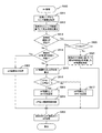
図9は、本発明の第1の実施の形態における撮像装置100による撮像画像記録処理の処理手順のうちのAF処理(図8に示すステップS910の処理手順)の一例を示すフローチャートである。この処理手順では、AF処理において、フォーカスレンズ移動範囲を設定してAF動作を実行するまでの流れを示す。
FIG. 9 is a flowchart illustrating an example of the AF process (the process procedure of step S910 illustrated in FIG. 8) in the process procedure of the captured image recording process performed by the
最初に、AF処理の開始時に、フォーカスレンズ移動範囲設定部340がレンズ情報保持部250に保持されているレンズ情報を取得する(ステップS911)。
First, at the start of AF processing, the focus lens movement
続いて、フォーカスレンズ移動範囲設定部340が、取得されたレンズ情報に基づいて、レンズの焦点深度を算出する(ステップS912)。ここで、レンズの焦点深度φは、式1を用いて算出される。
Subsequently, the focus lens movement
続いて、被写体速度Vが算出されたか否かが判断される(ステップS913)。すなわち、被写体の移動速度を算出することが可能な回数のAF処理が実行されたか否かが判断される。 Subsequently, it is determined whether or not the subject speed V has been calculated (step S913). That is, it is determined whether or not the number of AF processes that can calculate the moving speed of the subject has been executed.
被写体速度Vが算出されなかった場合には(ステップS913)、前回のAF処理において被写体の捕捉に失敗したか否かが判断される(ステップS914)。例えば、前回に比較的狭いフォーカスレンズ移動範囲が設定された場合には、このフォーカスレンズ移動範囲を用いて行われたAF処理において被写体の捕捉に失敗することも想定される。前回のAF処理において被写体の捕捉に失敗した場合には(ステップS914)、フォーカスレンズ移動範囲を拡大させる拡大処理が行われ(ステップS922)、ステップS923に進む。例えば、上述したように、前回のAF処理の結果がローコントラストであった場合には、その時点においてフォーカスレンズが移動可能な範囲の全てをフォーカスレンズ移動範囲とする。一方、至近端側がコントラストのピークであった場合には、その端点から至近側に所定量だけ広げた範囲を今回のフォーカスレンズ移動範囲とする。また、無限端がコントラストのピークであった場合には、その端点から至近側に所定量だけ広げた範囲を今回のフォーカスレンズ移動範囲とする。 If the subject speed V has not been calculated (step S913), it is determined whether or not the subject has failed to be captured in the previous AF process (step S914). For example, when a relatively narrow focus lens movement range is set last time, it is also assumed that the subject capture may fail in the AF process performed using this focus lens movement range. If capturing of the subject has failed in the previous AF process (step S914), an enlargement process for enlarging the focus lens movement range is performed (step S922), and the process proceeds to step S923. For example, as described above, when the result of the previous AF process is low contrast, the entire range in which the focus lens can move at that time is set as the focus lens movement range. On the other hand, when the close end side has a contrast peak, a range widened by a predetermined amount from the end point to the close side is set as the focus lens moving range this time. If the infinite end is a contrast peak, a range expanded by a predetermined amount from the end point to the closest side is set as the focus lens moving range this time.
また、前回のAF処理において被写体の捕捉に失敗していない場合には(ステップS914)、フォーカスレンズ移動範囲設定部340がフォーカスレンズ移動範囲AFR1およびAFR2を算出する(ステップS915)。ここで、フォーカスレンズ移動範囲AFR1は、焦点深度に基づいて算出されるフォーカスレンズ移動範囲である。また、フォーカスレンズ移動範囲AFR2は、撮像倍率に基づいて算出されるフォーカスレンズ移動範囲である。
If the subject has not failed to be captured in the previous AF process (step S914), the focus lens movement
続いて、フォーカスレンズ移動範囲設定部340が、算出されたフォーカスレンズ移動範囲AFR1およびAFR2を比較する(ステップS916)。この比較の結果、AFR2がAFR1以上である場合には(ステップS916)、フォーカスレンズ移動範囲設定部340が、フォーカスレンズ移動範囲AFR1を設定する(ステップS917)。
Subsequently, the focus lens movement
一方、AFR1がAFR2よりも大きい場合には(ステップS916)、フォーカスレンズ移動範囲設定部340が、フォーカスレンズ移動範囲AFR2を設定する(ステップS918)。このように、フォーカスレンズ移動範囲(AF範囲)としてAFR2が決定された場合には、フォーカスレンズ移動範囲設定部340が、AF最小範囲保障処理を行う(ステップS919)。すなわち、フォーカスレンズ移動範囲AFR2が、最低限必要な移動範囲Rminを満たしていない場合には、フォーカスレンズ移動範囲AFR3を設定する(ステップS919)。なお、ステップS915、S916、S918は、特許請求の範囲に記載の設定手順の一例である。
On the other hand, when AFR1 is larger than AFR2 (step S916), the focus lens movement
また、AF処理が複数回繰り返し行われ、被写体位置とその取得時刻とを記録しておくことにより、最低2回被写体が捕捉される。これにより被写体速度Vが算出される。被写体速度Vが算出された場合には(ステップS913)、被写体速度Vが閾値thV未満であるか否かが判断される(ステップS920)。ここで、焦点深度に対して被写体速度Vが極めて小さい場合には(ステップS920)、フォーカスレンズ移動範囲を充分に狭くすることが可能である。このため、ステップS915に進む。 Further, the AF process is repeatedly performed a plurality of times, and the subject is captured at least twice by recording the subject position and the acquisition time. Thereby, the subject speed V is calculated. When the subject speed V is calculated (step S913), it is determined whether the subject speed V is less than the threshold thV (step S920). Here, when the subject speed V is extremely small with respect to the focal depth (step S920), the focus lens moving range can be sufficiently narrowed. For this reason, it progresses to step S915.
一方、被写体速度Vが閾値thV以上である場合には(ステップS920)、被写体を捕捉可能なフォーカスレンズ移動範囲を設定する(ステップS921)。例えば、AF処理が繰り返し行われた場合には、ステップS904で求めた被写体速度Vを用いて、被写体移動分を考慮した次のフォーカスレンズ移動範囲が設定される(例えば、特開2010−8695号参照。)。 On the other hand, when the subject speed V is equal to or higher than the threshold thV (step S920), a focus lens moving range capable of capturing the subject is set (step S921). For example, when the AF process is repeatedly performed, the next focus lens movement range in consideration of the movement amount of the subject is set using the subject speed V obtained in step S904 (for example, Japanese Patent Laid-Open No. 2010-8695). reference.).
このように設定されたフォーカスレンズ移動範囲内においてフォーカスレンズ221を移動させることにより、AF処理が行われ(ステップS923)、AF処理の動作を終了する。なお、ステップS923は、特許請求の範囲に記載のフォーカス制御手順の一例である。
By moving the
<2.第2の実施の形態>
本発明の第1の実施の形態では、着脱式の交換レンズ200を撮像装置100に装着する撮像システム10において、一定条件を満たす場合には撮像倍率に基づいてフォーカスレンズ移動範囲を設定する例を示した。ただし、レンズ一体型のデジタルスチルカメラ等の撮像装置についても本発明の第1の実施の形態を適用することができる。そこで、本発明の第2の実施の形態では、レンズ一体型の撮像装置において、一定条件を満たす場合には撮像倍率に基づいてフォーカスレンズ移動範囲を設定する例について説明する。なお、本発明の第2の実施の形態における撮像装置の構成については、図1乃至図3に示す例と略同様である。このため、本発明の第1の実施の形態と共通する部分については、同一の符号を付して、これらの説明の一部(外観構成、機能構成等)を省略する。
<2. Second Embodiment>
In the first embodiment of the present invention, in the
[撮像装置の内部構成例]
図10は、本発明の第2の実施の形態における撮像装置800の内部構成例を示すブロック図である。撮像装置800は、ズーム位置検出部810と、モータドライバ820と、レンズ情報保持部830と、制御部840とを備える。なお、ズーム位置検出部810、モータドライバ820、レンズ情報保持部830および制御部840がシステムバス101を介して相互に通信可能となるように接続されている。
[Example of internal configuration of imaging device]
FIG. 10 is a block diagram illustrating an internal configuration example of an
ズーム位置検出部810は、ユーザによるズーム操作により駆動されたズームレンズ211の位置を検出するものであり、検出結果を制御部840に出力する。なお、ズーム位置検出部810は、図1に示すズーム位置検出部212に対応する。
The zoom
フォーカスレンズ駆動モータ222は、モータドライバ820の制御に基づいて、フォーカスレンズ221を移動させるものである。絞り駆動モータ232は、モータドライバ820の制御に基づいて、絞り231を駆動するものである。
The focus
モータドライバ820は、制御部840の制御に基づいて、フォーカスレンズ駆動モータ222および絞り駆動モータ232を駆動するドライバである。なお、モータドライバ820は、図1に示すモータドライバ240に対応する。
The
レンズ情報保持部830は、光学系を構成する各光学部材(フォーカスレンズ221、絞り231等)に関する固有の情報を保持するメモリであり、保持されている情報を制御部840に供給する。なお、レンズ情報保持部830は、図1に示すレンズ情報保持部250に対応する。また、固有の情報を他のメモリ(メモリ(ROM)140等)に保持させるようにしてもよい。
The lens
制御部840は、撮像装置100の各部(光学系を構成する各光学部材を含む)を制御するものである。なお、制御部840は、図1に示す制御部130およびレンズ制御部260に対応する。
The
このように、レンズ交換式の撮像装置以外に、レンズ一体型の撮像装置にも、本発明の第1の実施の形態を適用することができるため、コンティニュアスAFの改善を幅広く図ることができる。 As described above, since the first embodiment of the present invention can be applied to a lens-integrated image pickup apparatus in addition to a lens-interchangeable image pickup apparatus, continuous AF can be widely improved. it can.
また、以上で示したように、本発明の実施の形態によれば、コンティニュアスAFモードの設定時において、AF範囲を最適に設定することができる。この場合に、被写体への追尾性能を十分に保ちながら、ユーザの所望する画角調整や構図の調整を容易にし、撮影時にユーザに与える不快感を軽減することができる。 Further, as described above, according to the embodiment of the present invention, it is possible to optimally set the AF range when setting the continuous AF mode. In this case, it is possible to easily adjust the angle of view and the composition desired by the user while maintaining sufficient tracking performance on the subject, and to reduce discomfort given to the user during shooting.
また、被写体が停止している場合には、フォーカスレンズ移動範囲を極めて狭くすることができるため、被写体の動き出し判定をさらに高速化することができる。このように、本発明の実施の形態によれば、撮像動作時における視認性を維持して適切なフォーカス制御を行うことができる。 In addition, when the subject is stopped, the focus lens movement range can be extremely narrowed, so that it is possible to further speed up the subject movement start determination. Thus, according to the embodiment of the present invention, it is possible to perform appropriate focus control while maintaining visibility during the imaging operation.
なお、本発明の実施の形態は本発明を具現化するための一例を示したものであり、本発明の実施の形態において明示したように、本発明の実施の形態における事項と、特許請求の範囲における発明特定事項とはそれぞれ対応関係を有する。同様に、特許請求の範囲における発明特定事項と、これと同一名称を付した本発明の実施の形態における事項とはそれぞれ対応関係を有する。ただし、本発明は実施の形態に限定されるものではなく、本発明の要旨を逸脱しない範囲において実施の形態に種々の変形を施すことにより具現化することができる。 The embodiment of the present invention shows an example for embodying the present invention. As clearly shown in the embodiment of the present invention, the matters in the embodiment of the present invention and the claims Each invention-specific matter in the scope has a corresponding relationship. Similarly, the matters specifying the invention in the claims and the matters in the embodiment of the present invention having the same names as the claims have a corresponding relationship. However, the present invention is not limited to the embodiments, and can be embodied by making various modifications to the embodiments without departing from the gist of the present invention.
また、本発明の実施の形態において説明した処理手順は、これら一連の手順を有する方法として捉えてもよく、また、これら一連の手順をコンピュータに実行させるためのプログラム乃至そのプログラムを記憶する記録媒体として捉えてもよい。この記録媒体として、例えば、CD(Compact Disc)、MD(MiniDisc)、DVD(Digital Versatile Disk)、メモリカード、ブルーレイディスク(Blu-ray Disc(登録商標))等を用いることができる。 The processing procedure described in the embodiment of the present invention may be regarded as a method having a series of these procedures, and a program for causing a computer to execute the series of procedures or a recording medium storing the program May be taken as As this recording medium, for example, a CD (Compact Disc), an MD (MiniDisc), a DVD (Digital Versatile Disk), a memory card, a Blu-ray Disc (registered trademark), or the like can be used.
10 撮像システム
100、800 撮像装置
101 システムバス
102 閃光発光部
111 撮像素子
112 アナログ信号処理部
113 A/D変換部
114 DSP
115 表示部
116 記録デバイス
117 垂直ドライバ
118 TG
120 操作部
121 シャッターボタン
122 モードダイヤル
123 上下左右操作ボタン
124 決定ボタン
125 キャンセルボタン
126 電源スイッチ
130、840 制御部
200 交換レンズ
211 ズームレンズ
212、810 ズーム位置検出部
221 フォーカスレンズ
222 フォーカスレンズ駆動モータ
231 絞り
232 絞り駆動モータ
240、820 モータドライバ
250、830 レンズ情報保持部
260 レンズ制御部
310 撮像部
320 画像信号処理部
330 評価値生成部
340 フォーカスレンズ移動範囲設定部
350 フォーカス制御部
360 通信部
370 表示制御部
380 表示部
390 シャッター操作受付部
DESCRIPTION OF
120
Claims (10)
前記フォーカスレンズの位置に対応する撮像倍率を基準として当該基準からの撮像倍率の変化率が一定範囲内となる撮像倍率に対応するフォーカスレンズの位置に係る範囲を前記フォーカスレンズの移動範囲として設定する設定部と、
前記設定された移動範囲において前記フォーカスレンズを移動させることにより前記被写体に対するフォーカス制御を行うフォーカス制御部と
を具備する撮像装置。 An imaging unit that generates incident images by converting incident light from a subject incident via a focus lens;
Using the imaging magnification corresponding to the position of the focus lens as a reference, a range related to the position of the focus lens corresponding to the imaging magnification at which the change rate of the imaging magnification from the reference is within a certain range is set as the movement range of the focus lens. A setting section;
An imaging apparatus comprising: a focus control unit that performs focus control on the subject by moving the focus lens within the set movement range.
前記設定部は、前記算出された移動速度が一定値を基準として小さい場合にのみ前記撮像倍率に基づく移動範囲を設定する
請求項1記載の撮像装置。 A calculation unit that calculates a moving speed of the subject with respect to the optical axis direction;
The imaging apparatus according to claim 1, wherein the setting unit sets a movement range based on the imaging magnification only when the calculated moving speed is small with a constant value as a reference.
前記設定部は、前記移動範囲を設定する際に用いられる撮像倍率を前記交換レンズから取得する
請求項1記載の撮像装置。 A communication unit that communicates with an interchangeable lens that holds an imaging magnification corresponding to each state of the plurality of optical members for each state of the plurality of optical members;
The imaging apparatus according to claim 1, wherein the setting unit acquires an imaging magnification used when setting the moving range from the interchangeable lens.
前記設定部は、コンティニュアスAFモードが設定されている場合において前記生成された撮像画像が前記表示部に表示されている場合にのみ前記撮像倍率に基づく移動範囲を設定する
請求項1記載の撮像装置。 A display control unit for sequentially displaying the generated captured image on a display unit;
The setting unit sets a moving range based on the imaging magnification only when the generated captured image is displayed on the display unit when the continuous AF mode is set. Imaging device.
前記撮像装置との間で通信を行う第一通信部と、
前記複数の光学部材の各状態に応じた撮像倍率を前記複数の光学部材の状態毎に保持する保持部とを備える交換レンズと、
前記交換レンズとの間で通信を行う第二通信部と、
フォーカスレンズを介して入射される被写体からの入射光を変換して撮像画像を生成する撮像部と、
前記フォーカスレンズの位置に係る撮像倍率を前記保持部から取得して当該フォーカスレンズの位置に対応する撮像倍率を基準として当該基準からの変化率が一定範囲内となる撮像倍率に対応するフォーカスレンズの位置に係る範囲を前記フォーカスレンズの移動範囲として設定する設定部と、
前記設定された移動範囲において前記フォーカスレンズを移動させることにより前記被写体に対するフォーカス制御を行うフォーカス制御部とを備える撮像装置と
を具備する撮像システム。 A plurality of optical members;
A first communication unit that communicates with the imaging device;
An interchangeable lens comprising: a holding unit that holds an imaging magnification corresponding to each state of the plurality of optical members for each state of the plurality of optical members;
A second communication unit for communicating with the interchangeable lens;
An imaging unit that generates incident images by converting incident light from a subject incident via a focus lens;
An imaging magnification corresponding to the position of the focus lens is acquired from the holding unit, and a focus lens corresponding to an imaging magnification whose rate of change from the reference is within a certain range with reference to the imaging magnification corresponding to the position of the focus lens. A setting unit for setting a range related to the position as a moving range of the focus lens;
An imaging system comprising: an imaging device including a focus control unit that performs focus control on the subject by moving the focus lens within the set movement range.
前記設定された移動範囲において前記フォーカスレンズを移動させることにより前記被写体に対するフォーカス制御を行うフォーカス制御手順と
を具備する撮像装置の制御方法。 Based on the imaging magnification corresponding to the position of the focus lens that supplies incident light from the subject to the imaging unit that generates the captured image, the position of the focus lens corresponding to the imaging magnification where the rate of change from the reference is within a certain range A setting procedure for setting such a range as a moving range of the focus lens;
A control method for an imaging apparatus, comprising: a focus control procedure for performing focus control on the subject by moving the focus lens within the set movement range.
前記設定された移動範囲において前記フォーカスレンズを移動させることにより前記被写体に対するフォーカス制御を行うフォーカス制御手順と
をコンピュータに実行させるプログラム。 Based on the imaging magnification corresponding to the position of the focus lens that supplies incident light from the subject to the imaging unit that generates the captured image, the position of the focus lens corresponding to the imaging magnification where the rate of change from the reference is within a certain range A setting procedure for setting such a range as a moving range of the focus lens;
A program that causes a computer to execute a focus control procedure for performing focus control on the subject by moving the focus lens within the set movement range.
Priority Applications (3)
| Application Number | Priority Date | Filing Date | Title |
|---|---|---|---|
| JP2010122167A JP2011248159A (en) | 2010-05-28 | 2010-05-28 | Imaging apparatus, imaging system, imaging apparatus control method and program |
| US13/078,414 US8947579B2 (en) | 2010-05-28 | 2011-04-01 | Imaging apparatus, imaging system, and imaging apparatus control method and program for setting a range of lens positions |
| CN201110122020.2A CN102262334B (en) | 2010-05-28 | 2011-05-12 | Imaging device, imaging system and imaging apparatus control method |
Applications Claiming Priority (1)
| Application Number | Priority Date | Filing Date | Title |
|---|---|---|---|
| JP2010122167A JP2011248159A (en) | 2010-05-28 | 2010-05-28 | Imaging apparatus, imaging system, imaging apparatus control method and program |
Publications (2)
| Publication Number | Publication Date |
|---|---|
| JP2011248159A true JP2011248159A (en) | 2011-12-08 |
| JP2011248159A5 JP2011248159A5 (en) | 2013-05-30 |
Family
ID=45009018
Family Applications (1)
| Application Number | Title | Priority Date | Filing Date |
|---|---|---|---|
| JP2010122167A Pending JP2011248159A (en) | 2010-05-28 | 2010-05-28 | Imaging apparatus, imaging system, imaging apparatus control method and program |
Country Status (3)
| Country | Link |
|---|---|
| US (1) | US8947579B2 (en) |
| JP (1) | JP2011248159A (en) |
| CN (1) | CN102262334B (en) |
Cited By (1)
| Publication number | Priority date | Publication date | Assignee | Title |
|---|---|---|---|---|
| JP2013142882A (en) * | 2012-01-13 | 2013-07-22 | Canon Inc | Imaging apparatus, lens device, and method for controlling imaging apparatus |
Families Citing this family (17)
| Publication number | Priority date | Publication date | Assignee | Title |
|---|---|---|---|---|
| EP2582126A4 (en) * | 2010-07-14 | 2014-08-13 | Lg Electronics Inc | Autofocus device and a method therefor |
| TWI440951B (en) * | 2011-11-09 | 2014-06-11 | Altek Corp | Lens actuating device and lens actuating method thereof |
| CN108387996B (en) * | 2011-11-11 | 2020-11-03 | 株式会社尼康 | Focus adjustment control device, imaging device, and lens barrel |
| JP5948856B2 (en) * | 2011-12-21 | 2016-07-06 | ソニー株式会社 | Imaging apparatus, autofocus method, and program |
| JP5586796B2 (en) * | 2011-12-28 | 2014-09-10 | 富士フイルム株式会社 | Imaging device, control method thereof, interchangeable lens and interchangeable lens imaging device body |
| JP5559242B2 (en) * | 2012-05-15 | 2014-07-23 | キヤノン株式会社 | Interchangeable lens, camera and camera system |
| JP6145822B2 (en) * | 2012-10-12 | 2017-06-14 | パナソニックIpマネジメント株式会社 | Imaging device |
| JP5709829B2 (en) * | 2012-12-17 | 2015-04-30 | キヤノン株式会社 | External device, control method of external device, imaging system, and control method of imaging system |
| JP6137840B2 (en) * | 2013-01-18 | 2017-05-31 | オリンパス株式会社 | Camera system |
| JP6234294B2 (en) * | 2014-03-25 | 2017-11-22 | オリンパス株式会社 | Camera system |
| JP6028876B1 (en) * | 2016-02-02 | 2016-11-24 | ソニー株式会社 | Lens unit, imaging device, and control method |
| JP6641594B2 (en) | 2016-02-02 | 2020-02-05 | ソニー株式会社 | Interchangeable lens and its communication method, and imaging device and its communication method |
| CN106096795B (en) * | 2016-02-24 | 2022-04-08 | 皮尔公司 | Safety platform and data repository for fur or skin goods |
| US10466158B2 (en) * | 2017-04-11 | 2019-11-05 | Sony Corporation | Microparticle sorting apparatus and delay time determination method |
| CN111630427B (en) * | 2018-01-25 | 2022-04-01 | 富士胶片株式会社 | Image pickup apparatus, image pickup method, and storage medium |
| WO2019187382A1 (en) * | 2018-03-30 | 2019-10-03 | 富士フイルム株式会社 | Focus control device, focus control method, and program |
| JP2022078863A (en) * | 2020-11-13 | 2022-05-25 | ソニー・オリンパスメディカルソリューションズ株式会社 | Medical control apparatus and medical observation system |
Citations (6)
| Publication number | Priority date | Publication date | Assignee | Title |
|---|---|---|---|---|
| JPH0698234A (en) * | 1992-09-10 | 1994-04-08 | Canon Inc | Camera |
| JPH09211654A (en) * | 1996-01-31 | 1997-08-15 | Minolta Co Ltd | Lens interchangeable camera |
| JP2008170508A (en) * | 2007-01-09 | 2008-07-24 | Elmo Co Ltd | Imaging apparatus |
| JP2009115921A (en) * | 2007-11-02 | 2009-05-28 | Olympus Corp | Imaging apparatus |
| JP2010049176A (en) * | 2008-08-25 | 2010-03-04 | Canon Inc | Automatic focusing device and control method therefor |
| JP2010113291A (en) * | 2008-11-10 | 2010-05-20 | Olympus Corp | Imaging apparatus |
Family Cites Families (7)
| Publication number | Priority date | Publication date | Assignee | Title |
|---|---|---|---|---|
| JP4836320B2 (en) * | 2000-12-13 | 2011-12-14 | 富士フイルム株式会社 | Angle correction device for taking lens |
| JP2006301036A (en) * | 2005-04-15 | 2006-11-02 | Sony Corp | Autofocus system, autofocus method, and program |
| JP2007011140A (en) * | 2005-07-01 | 2007-01-18 | Olympus Imaging Corp | Camera system with camera shake correcting function |
| JP5013705B2 (en) * | 2005-11-21 | 2012-08-29 | 三星電子株式会社 | Imaging device, screen display method, focus adjustment method, exposure adjustment method, and computer program |
| JP4535173B2 (en) | 2008-06-26 | 2010-09-01 | ソニー株式会社 | Imaging apparatus, focus control method, and program |
| JP5290691B2 (en) * | 2008-10-07 | 2013-09-18 | キヤノン株式会社 | Autofocus device |
| US8126322B2 (en) * | 2009-03-13 | 2012-02-28 | Panasonic Corporation | Interchangeable lens, camera body, and camera system |
-
2010
- 2010-05-28 JP JP2010122167A patent/JP2011248159A/en active Pending
-
2011
- 2011-04-01 US US13/078,414 patent/US8947579B2/en active Active
- 2011-05-12 CN CN201110122020.2A patent/CN102262334B/en not_active Expired - Fee Related
Patent Citations (6)
| Publication number | Priority date | Publication date | Assignee | Title |
|---|---|---|---|---|
| JPH0698234A (en) * | 1992-09-10 | 1994-04-08 | Canon Inc | Camera |
| JPH09211654A (en) * | 1996-01-31 | 1997-08-15 | Minolta Co Ltd | Lens interchangeable camera |
| JP2008170508A (en) * | 2007-01-09 | 2008-07-24 | Elmo Co Ltd | Imaging apparatus |
| JP2009115921A (en) * | 2007-11-02 | 2009-05-28 | Olympus Corp | Imaging apparatus |
| JP2010049176A (en) * | 2008-08-25 | 2010-03-04 | Canon Inc | Automatic focusing device and control method therefor |
| JP2010113291A (en) * | 2008-11-10 | 2010-05-20 | Olympus Corp | Imaging apparatus |
Cited By (1)
| Publication number | Priority date | Publication date | Assignee | Title |
|---|---|---|---|---|
| JP2013142882A (en) * | 2012-01-13 | 2013-07-22 | Canon Inc | Imaging apparatus, lens device, and method for controlling imaging apparatus |
Also Published As
| Publication number | Publication date |
|---|---|
| CN102262334B (en) | 2015-10-28 |
| US20110292272A1 (en) | 2011-12-01 |
| CN102262334A (en) | 2011-11-30 |
| US8947579B2 (en) | 2015-02-03 |
Similar Documents
| Publication | Publication Date | Title |
|---|---|---|
| JP2011248159A (en) | Imaging apparatus, imaging system, imaging apparatus control method and program | |
| JP5609270B2 (en) | IMAGING DEVICE, IMAGING SYSTEM, IMAGING DEVICE CONTROL METHOD, AND PROGRAM | |
| JP5054583B2 (en) | Imaging device | |
| JP6063634B2 (en) | Focus adjustment device | |
| JP4727534B2 (en) | Imaging device | |
| WO2013088917A1 (en) | Image processing device, image processing method, and recording medium | |
| JP2006301378A (en) | Imaging apparatus | |
| JP2011205282A (en) | Imaging apparatus and image processing method | |
| JP2007215091A (en) | Imaging apparatus and program therefor | |
| JP5855454B2 (en) | Imaging device | |
| JP2010183472A (en) | Imaging apparatus, and program | |
| JP5546691B2 (en) | Imaging apparatus, imaging method, and program | |
| JP2009169282A (en) | Imaging apparatus and its program | |
| JP5100410B2 (en) | Imaging apparatus and control method thereof | |
| JP5367129B2 (en) | Imaging apparatus, control apparatus, and control method thereof | |
| JP2009081810A (en) | Photographing device and photographing method | |
| JP6220144B2 (en) | Focus adjustment apparatus and control method thereof | |
| JP6087714B2 (en) | Imaging apparatus and control method thereof | |
| JP2007225897A (en) | Focusing position determination device and method | |
| JP2014056153A (en) | Focus adjustment device, imaging device, and control method therefor | |
| JP6624789B2 (en) | Focus control device, control method thereof, control program, and imaging device | |
| JP2007094023A (en) | Focus adjustment method of focus lens and imaging apparatus | |
| JP5493273B2 (en) | Imaging apparatus, imaging method, and program | |
| JP2011013499A (en) | Imaging apparatus | |
| JP2007108217A (en) | Digital camera |
Legal Events
| Date | Code | Title | Description |
|---|---|---|---|
| A521 | Request for written amendment filed |
Free format text: JAPANESE INTERMEDIATE CODE: A523 Effective date: 20130408 |
|
| A621 | Written request for application examination |
Free format text: JAPANESE INTERMEDIATE CODE: A621 Effective date: 20130408 |
|
| A977 | Report on retrieval |
Free format text: JAPANESE INTERMEDIATE CODE: A971007 Effective date: 20140219 |
|
| A131 | Notification of reasons for refusal |
Free format text: JAPANESE INTERMEDIATE CODE: A131 Effective date: 20140311 |
|
| A521 | Request for written amendment filed |
Free format text: JAPANESE INTERMEDIATE CODE: A523 Effective date: 20140507 |
|
| A02 | Decision of refusal |
Free format text: JAPANESE INTERMEDIATE CODE: A02 Effective date: 20150303 |